Embed Size (px)
Citation preview
Chapter 5: Telescopes!
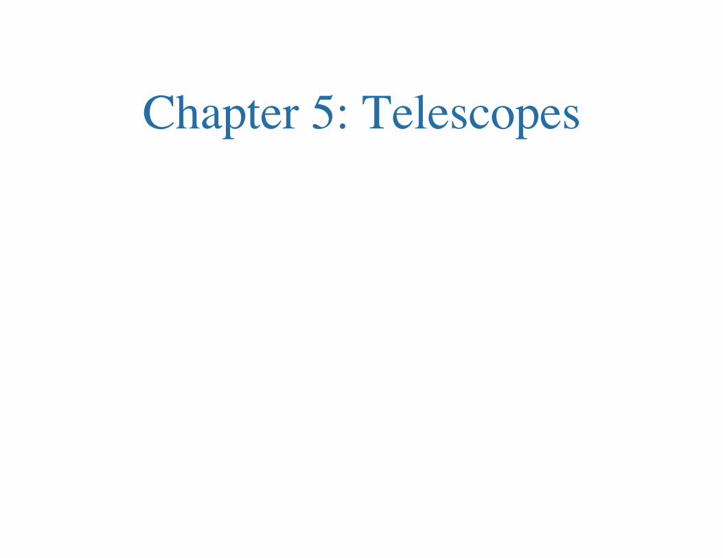
You don’t have to know different
types of reflecting and refracting
telescopes.!
Why build bigger and bigger telescopes?"
There are a few reasons. The first is:!
Light-gathering power: !Obviously bigger telescopes can collect more light, because the amount
gathered just depends on the area of the telescope (diameter squared).!
This property determines the ability to see faint objects. Faint objects might not be nearby, but could be very distant. So need a large telescope to see the faintest, nearby objects in the universe, and the most distant. !
You also need a LOT of light to obtain spectra with high enough spectral resolution to analyze spectral lines! !
(Think about it--you’re trying to study a tiny fraction of the entire spectrum of an object if you try to analyze a spectral line.)!
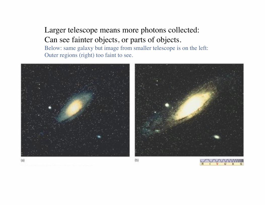
Larger telescope means more photons collected: !
Can see fainter objects, or parts of objects.!Below: same galaxy but image from smaller telescope is on the left: !
Outer regions (right) too faint to see.!
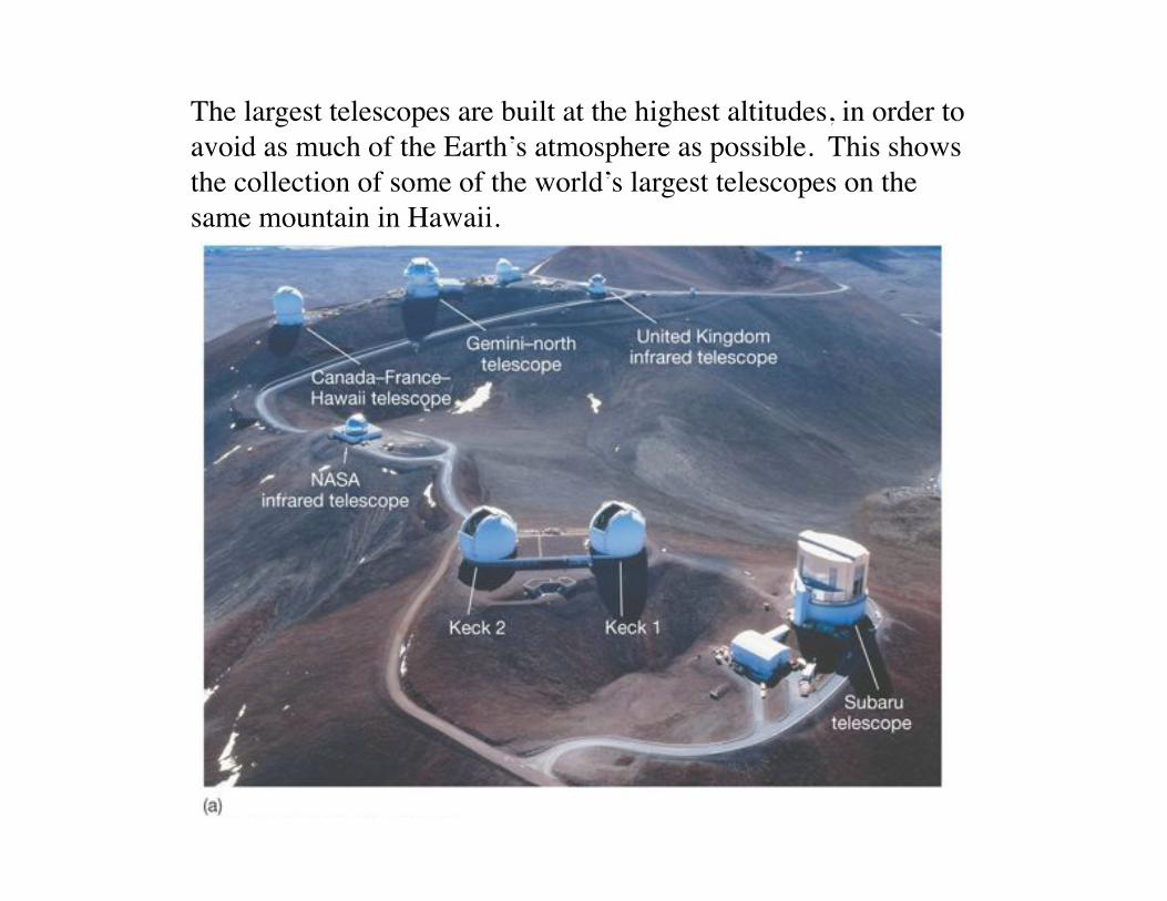
The largest telescopes are built at the highest altitudes, in order to!
avoid as much of the Earth’s atmosphere as possible. This shows!
the collection of some of the world’s largest telescopes on the !
same mountain in Hawaii.!
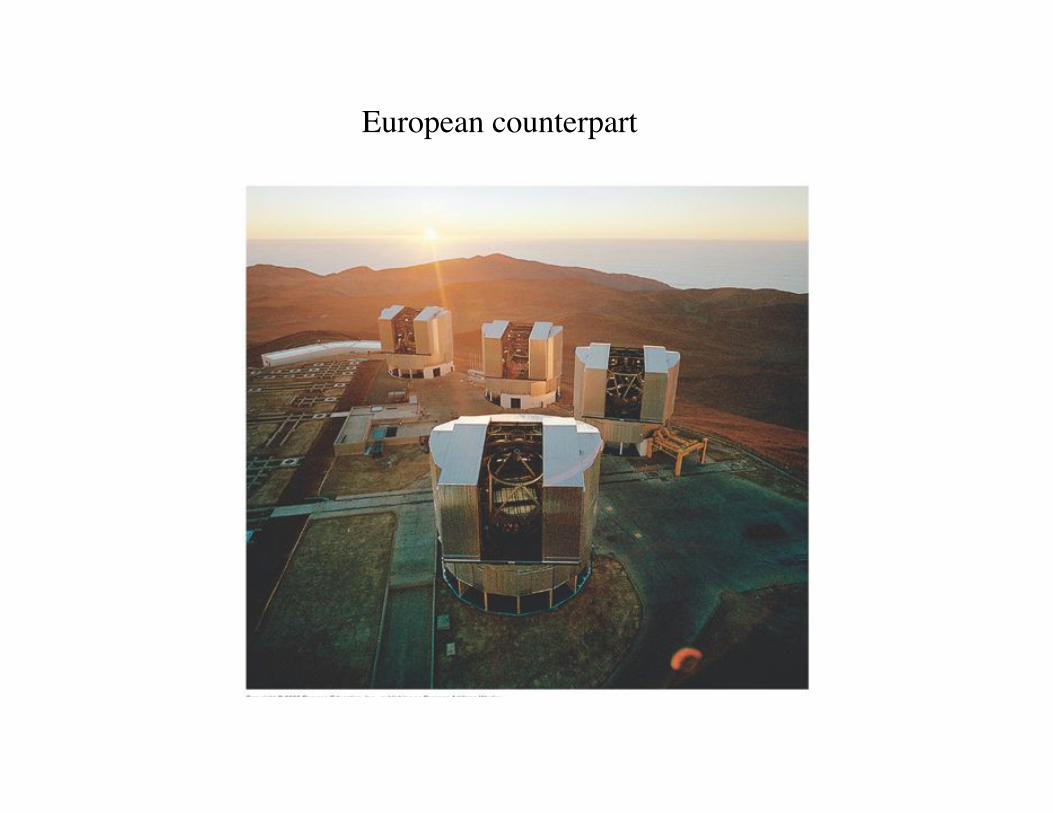
European counterpart!
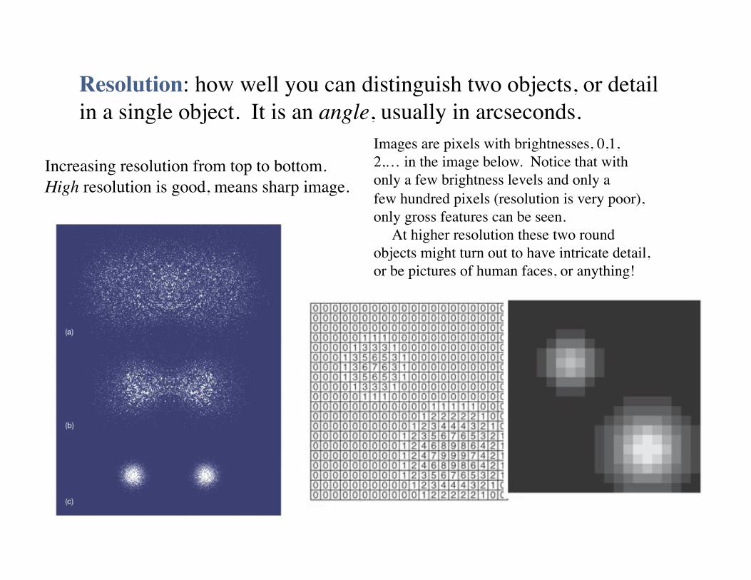
Resolution: how well you can distinguish two objects, or detail !
in a single object. It is an angle, usually in arcseconds.!
Increasing resolution from top to bottom.!
High resolution is good, means sharp image.!
Images are pixels with brightnesses, 0,1,!
2,… in the image below. Notice that with !
only a few brightness levels and only a !
few hundred pixels (resolution is very poor),!
only gross features can be seen.!
At higher resolution these two round !
objects might turn out to have intricate detail,!
or be pictures of human faces, or anything!!
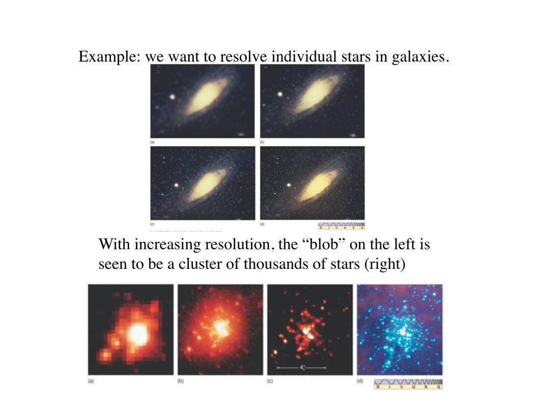
Example: we want to resolve individual stars in galaxies.!
With increasing resolution, the “blob” on the left is !
seen to be a cluster of thousands of stars (right)!
How to enhance resolution? First must understand the limitations,!
which are !
1.! The “seeing limit” (Earth’s atmosphere), and !
2.! The “diffraction limit” (inherent in observing through an instrument)!
Note: if you have trouble remembering “resolution”, remember that!
poor resolution means “blurry,” and is equivalent to being nearsighted,!
or having a digital camera with only 0.2 megapixels. !
Resolution (continued)!
The diffraction limit!
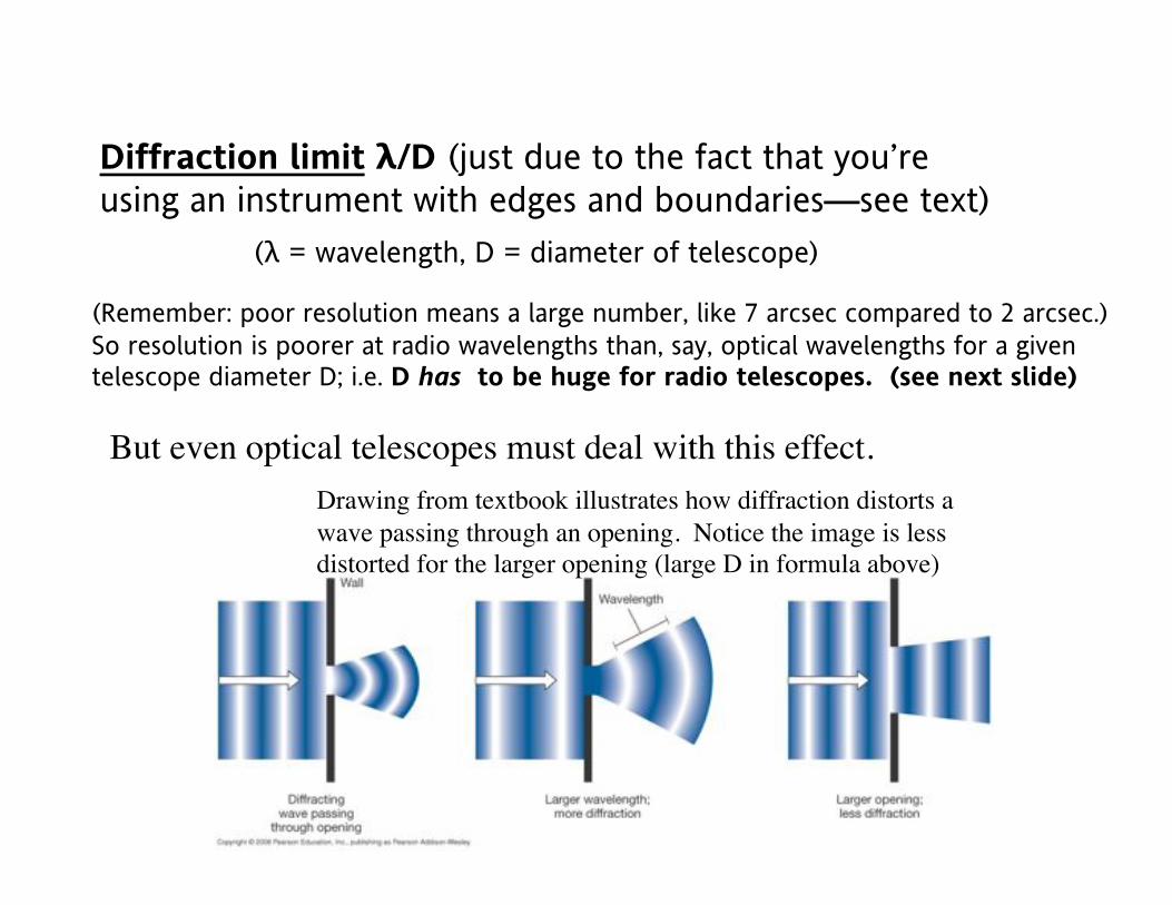
Diffraction limit !/D (just due to the fact that you’re
using an instrument with edges and boundaries—see text)
(Remember: poor resolution means a large number, like 7 arcsec compared to 2 arcsec.)
So resolution is poorer at radio wavelengths than, say, optical wavelengths for a given telescope diameter D; i.e. D has to be huge for radio telescopes. (see next slide)!
(! = wavelength, D = diameter of telescope)
But even optical telescopes must deal with this effect. !
Drawing from textbook illustrates how diffraction distorts a !
wave passing through an opening. Notice the image is less !
distorted for the larger opening (large D in formula above)!
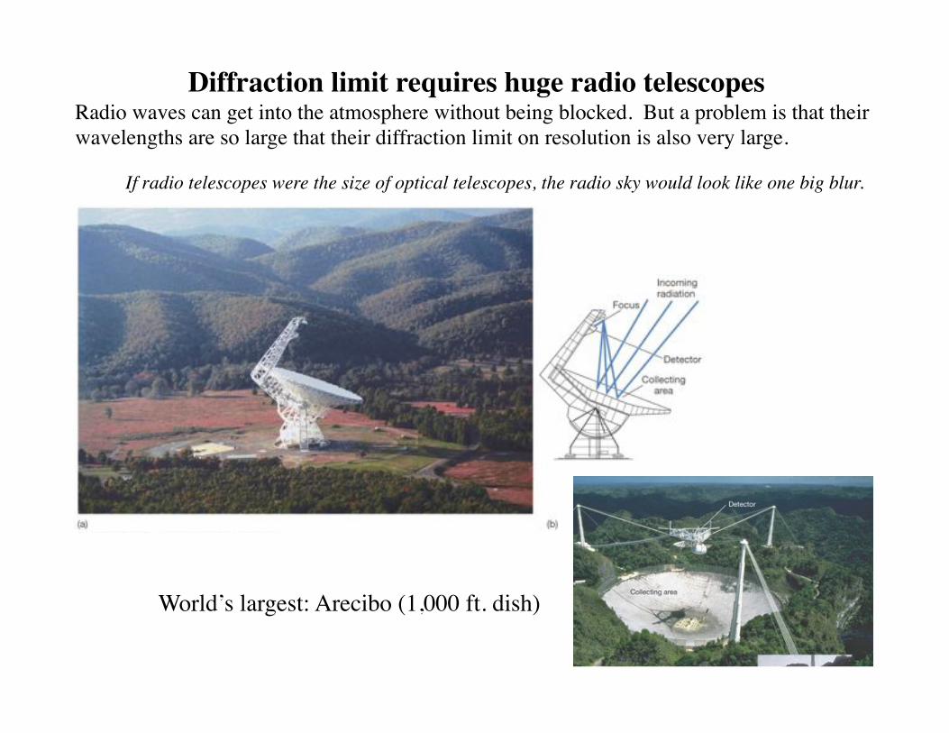
Diffraction limit requires huge radio telescopes!Radio waves can get into the atmosphere without being blocked. But a problem is that their
wavelengths are so large that their diffraction limit on resolution is also very large. !
If radio telescopes were the size of optical telescopes, the radio sky would look like one big blur.!
World’s largest: Arecibo (1,000 ft. dish)!
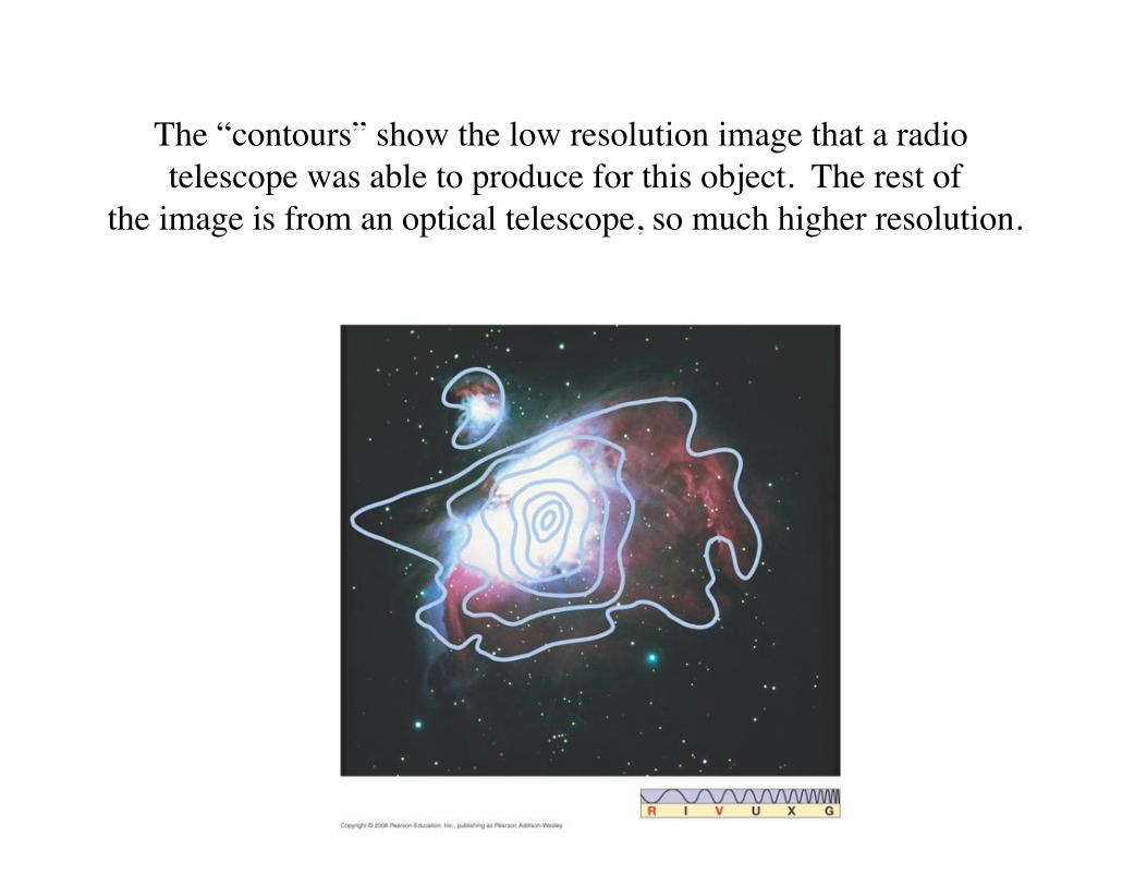
The “contours” show the low resolution image that a radio !
telescope was able to produce for this object. The rest of!
the image is from an optical telescope, so much higher resolution.!
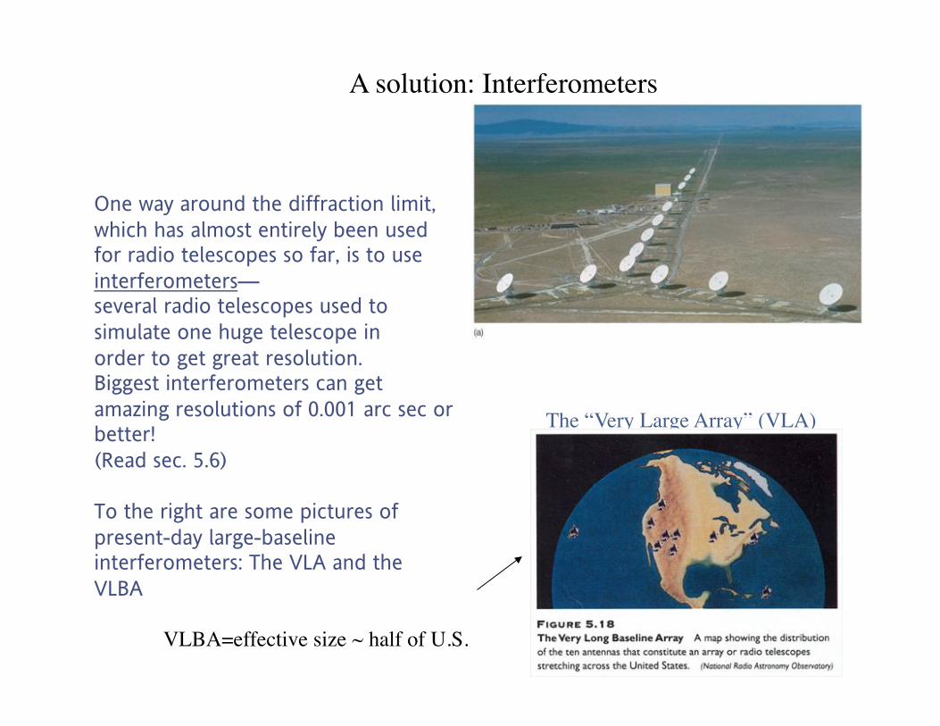
One way around the diffraction limit,
which has almost entirely been used for radio telescopes so far, is to use
interferometers— several radio telescopes used to
simulate one huge telescope in
order to get great resolution. Biggest interferometers can get
amazing resolutions of 0.001 arc sec or better!
(Read sec. 5.6)
To the right are some pictures of
present-day large-baseline interferometers: The VLA and the
VLBA!
A solution: Interferometers!
The “Very Large Array” (VLA)!
VLBA=effective size ~ half of U.S.!
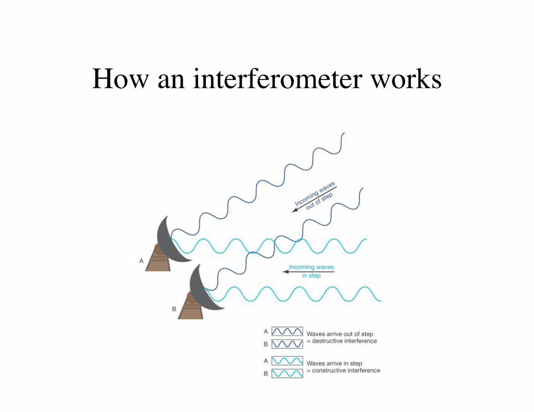
How an interferometer works!
The Seeing Limit!
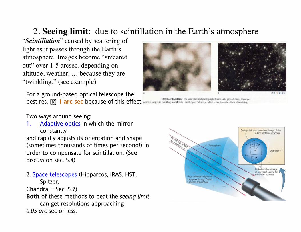
2. Seeing limit: due to scintillation in the Earth’s atmosphere!
For a ground-based optical telescope the best res. ! 1 arc sec because of this effect.
Two ways around seeing: 1.! Adaptive optics in which the mirror
constantly and rapidly adjusts its orientation and shape (sometimes thousands of times per second!) in
order to compensate for scintillation. (See discussion sec. 5.4)
2. Space telescopes (Hipparcos, IRAS, HST, Spitzer,
Chandra,…Sec. 5.7) Both of these methods to beat the seeing limit
can get resolutions approaching 0.05 arc sec or less.
“Scintillation” caused by scattering of
light as it passes through the Earth’s
atmosphere. Images become “smeared
out” over 1-5 arcsec, depending on
altitude, weather, … because they are
“twinkling.” (see example)!
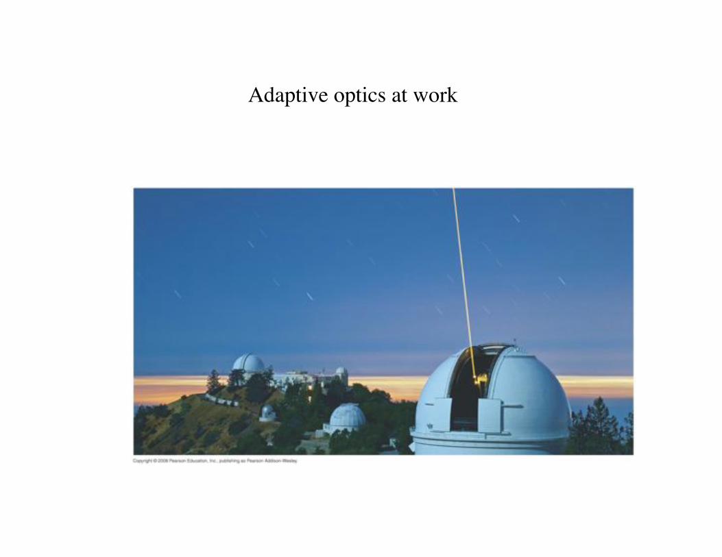
Adaptive optics at work!
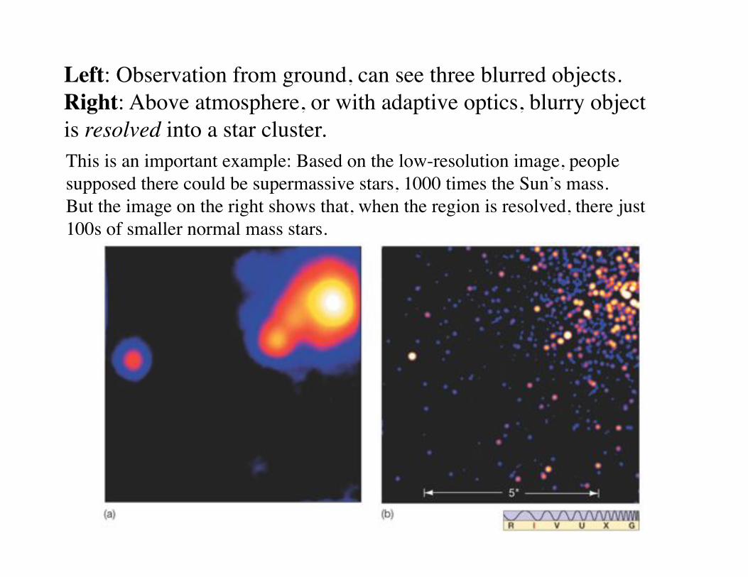
Left: Observation from ground, can see three blurred objects.!
Right: Above atmosphere, or with adaptive optics, blurry object!
is resolved into a star cluster. !
This is an important example: Based on the low-resolution image, people
supposed there could be supermassive stars, 1000 times the Sun’s mass. !
But the image on the right shows that, when the region is resolved, there just
100s of smaller normal mass stars.!
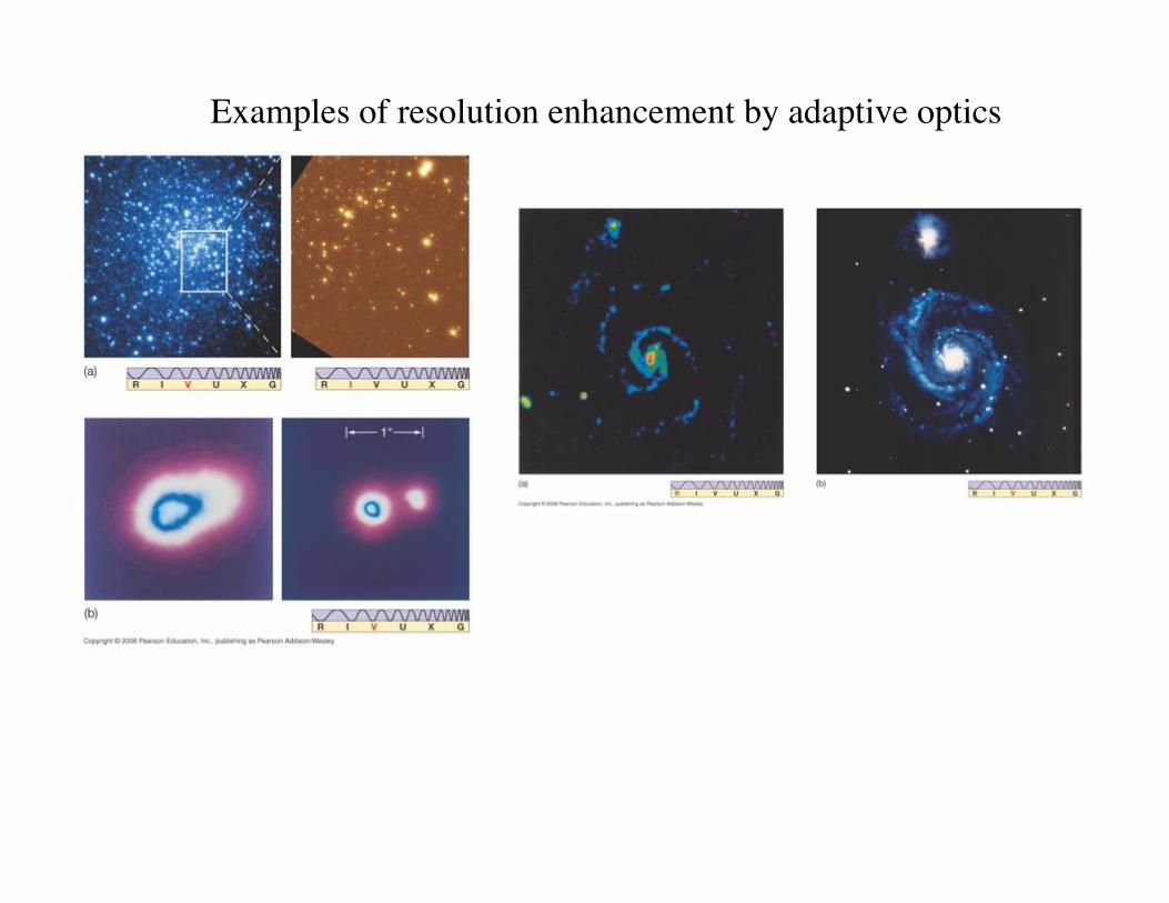
Examples of resolution enhancement by adaptive optics!
Important additional considerations!
1. Atmospheric transmission--Besides being responsible for seeing, the Earth’s atmosphere also just blocks out light. Visible and radio wavelengths are
least affected (recall material from ch.3). For other wavelength regions, need satellite observatories or at least very high mountains (same for
visible because of seeing). (Sec. 5.7)
2. CCDs—Photographic plates only capture about 1% of the light, while
charge-coupled devices (CCDs) can get about 75% efficiency, and extremely accurate. (sec. 5.2 in text). For optical telescopes, photographic plates
are no longer used.
3. Infrared telescopes—special problem: must be cold, because the telescope
itself emits IR radiation (why?). Also, best when above the Earth’s atmosphere to avoid molecular absorption (see 1 above). (Sec. 5.7)
4. X-ray and gamma-ray observations—All must be done far up in Earth’s atmosphere because absorption is so strong. Need special telescopes, since these
don’t reflect off mirrors the way that longer-wavelength light does (why not?). See book sec. 5.7 for more details.
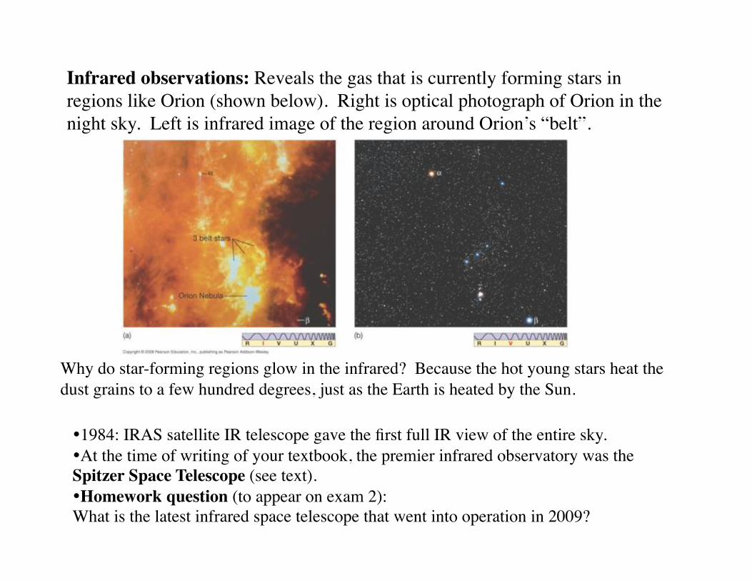
Infrared observations: Reveals the gas that is currently forming stars in
regions like Orion (shown below). Right is optical photograph of Orion in the
night sky. Left is infrared image of the region around Orion’s “belt”.!
Why do star-forming regions glow in the infrared? Because the hot young stars heat the
dust grains to a few hundred degrees, just as the Earth is heated by the Sun.!
!1984: IRAS satellite IR telescope gave the first full IR view of the entire sky.!
!At the time of writing of your textbook, the premier infrared observatory was the
Spitzer Space Telescope (see text). !
!Homework question (to appear on exam 2): !
What is the latest infrared space telescope that went into operation in 2009?!
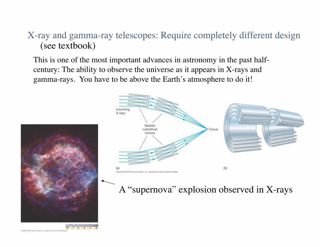
X-ray and gamma-ray telescopes: Require completely different design!(see textbook)!
This is one of the most important advances in astronomy in the past half-
century: The ability to observe the universe as it appears in X-rays and
gamma-rays. You have to be above the Earth’s atmosphere to do it!!
A “supernova” explosion observed in X-rays!
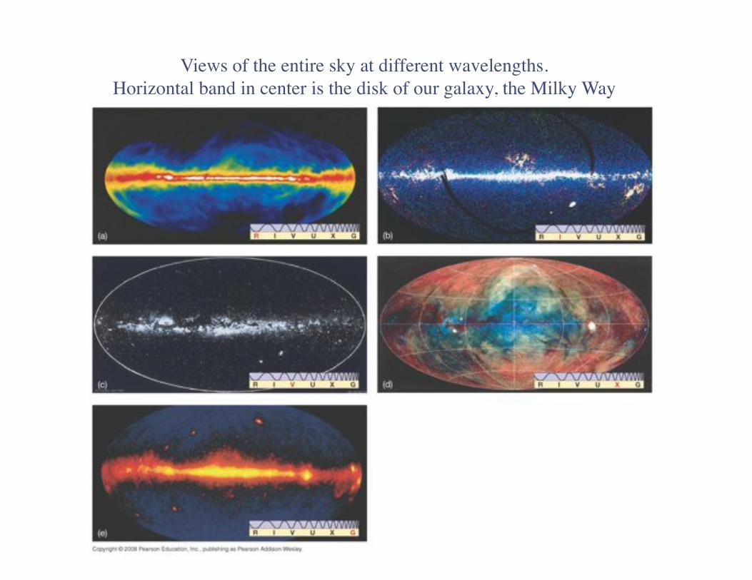
Views of the entire sky at different wavelengths.!
Horizontal band in center is the disk of our galaxy, the Milky Way!
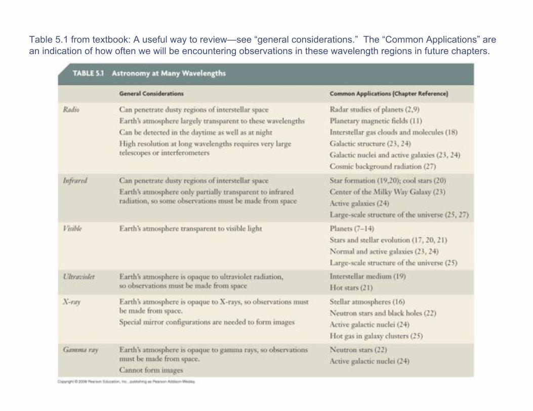
Table 5.1 from textbook: A useful way to review—see “general considerations.” The “Common Applications” are
an indication of how often we will be encountering observations in these wavelength regions in future chapters.