Embed Size (px)
Citation preview

1
CHAPTER 4
SITE PLANNING & EXTERNAL FIRE FIGHTING PROVISION
4.1 General
4.1.1 The purpose of this Chapter of the Code is to make provision for
space around buildings to enable effective mounting of rescue and external fire fighting operations.
4.2 PROVISION FOR EXTERNAL ACCESS TO BUILDING FOR FIRE FIGHTING AND ACCESIBILITY OF SITE TO FIRE FIGHTTING APPLIANCES
4.2.1 Introduction
Accessway shall be provided for accessibility of site to fire fightingappliances. To permit fire fighting appliances to be deployed, theaccessway shall have a minimum width of 6m throughout its entirelength. Access openings shall be provided along the external walls ofbuildings fronting the accessway to provide access into the building forfire fighting and rescue operations.
Diagram 4.2.1

2
Every institutional development shall be provided with accessibility for fire fighting appliances. The internal driveways shall be constructed to have the required width and be able to withstand the operational loading of fire engine when conducting external fire fighting. Access openings along the external walls of the buildings facing the accessway shall be provided for the purpose of conducting fire fighting and rescue operations.
4.2.2 ACCESSWAY FOR FIRE FIGHTING APPLIANCES
(a) (iv) For buildings under purpose group III not exceeding the habitable height of 10m, accessway will not be required. However, provision of fire engine access road having minimum 4m width for pump appliance will be required to within a travel distance of 45m of every point on the projected plan area of the building.
Diagram 4.2.2(a)(iv)
The measurement of the travel distance shall be the line of travel located outside the building, and shall not traverse across open sided porches or 1st storey void deck. The travel distance is the distance that a fire fighter would traverse while carrying a portable ladder or equipment.

3
4.2.2 (b) (i) For buildings under purpose group III exceeding the habitable height of 10m, accessway shall be located directly below the access openings to provide direct outreach to the access openings. Accessway shall be provided based on the gross floor area (including toilets, stores, circulation areas, etc.) of the largest floor in the building as follows:
Minimum 1/6 perimeter ( min 15m) 2000m2 to 4000m2 ¼ perimeter >4000m2 to 8000m2 ½ perimeter >8000m2 to 16,000m2 ¾ perimeter >16000m2 island site access
For buildings protected by an automatic sprinkler system, the floor area shall be doubled as follows:
Minimum 1/6 perimeter ( min 15m) 4000m2 to 8000m2 ¼ perimeter >8000m2 to 16,000m2 ½ perimeter >16,000m2 to 32,000m2 ¾ perimeter >32,000m2 island site access.
Diagram 4.2.2(b)(i)-1

4
Diagram 4.2.2(b)(i)-2
In the event the service road (Minimum 6m) is accessible by fire fighting appliances and the building volume exceeds 2000m2 but is less than 4000m2, then A + C ≥ ¼ ( A + B + C + D )
Diagram 4.2.2(b)(i)-3

5
a. It is important to note that for purpose groups III buildings, the gross floor area of the largest floor in the building is used for the calculation of the extent of accessway required.
b. Sprinklered protected buildings For buildings protected by an automatic sprinkler system, the gross floor area of the largest floor in the building can be doubled.
(ii) Fire engine access road shall be provided to within 18m of breeching inlet for buildings that exceed the habitable height of 10m.
4.2.2 (d) (i) Accessway
Accessway shall be metalled or paved or laid with strengthened perforated slabs to withstand the loading capacity of stationary 30 tonnes fire engine. Please see Appendix (G) for technical data on fire engine.
Diagram 4.2.2(d)(i) - 1
Accessway needs to be designed to take the operating load of the fire engine.
Diagram A to Appendix G shows the location of footplates (jacks).
Where cellular or precast perforated slabs are to be used, they shall be of the approved type.

6
Appendix G Structural Loading of Fire Engine on Accessway
The following information will assist structural engineers in the design of accessway.
(i) Accessway Size
In general, the minimum width of the accessway shall be 6m wide and the minimum length shall be 15m long. Diagram A shows the relationship between the accessway and parked fire engine with its front and rear jacks extended.
(ii) Accessway Loading
Accessway shall be on (a) suspended slabs, or (b) on metalled or paved ground, or (c) ground laid with strengthened perforated slabs or (d) approved materials to withstand the loading requirements of fire engine. (iii) The accessway required to serve building shall be constructed to
sustain the load of a 30 tonnes fire engine. The wheel load shall be considered separately with the jack loads for both global and local effects.
(iv) Axles Load
Axles load for accessway shall be as follows : Front Axle 7500kg 2 wheels Rear Axle 21,000kg 8 wheels (v) The jack load shall be assumed to be uniformly distributed over a
rectangular contact area of 923 cm² for both local and global analysis.
(v) The maximum pressure on one jack, even in the worst case, will not
exceed 80N/cm².
(vi) In the absence of more exact calculations, live load surcharge for accessway on suitable material properly consolidated may be assumed to be at least 10KN/m².

7
Diagram A
ACCESSWAY (WHEELS & JACKS LAYOUT)
Wheel Spacing
5384mm

8
4.2.2 (d) (ii) Width of accessway
The accesssway shall have a minimum width of 6m throughout. Such accessway must be able to accommodate the entry and manoeuvring of fire engine, extended ladders pumping appliances, turntable and / or hydraulic platforms. (No illustration)
(iii) Location
Accessway shall be positioned so that the nearer edge shall be not less than 2m or more than 10m from the centre position of the access opening, measured horizontally. (For illustration, see diagram 4.2.3(e)-1)
(iv) Gradient Of Acessway Accessway shall be laid on a level platform or if on an incline,
the gradient shall not exceed 1:15.
(No illustration)
Gradient of 1:8.3 of normal driveway or accessway could be used by fire engines for moving from one point to another. For hardstanding the inclined gradient shall not exceeds 1:15 as the fire engine would not be able to operate.
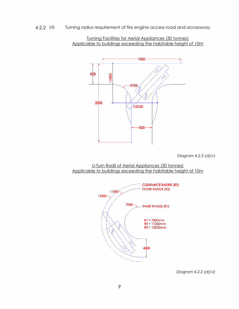
(v) Turning facilities
Dead-end accessway and fire engine access road shall not exceed 46 m in length or if exceeding 46 m, be provided with turning facilities as shown in Diagram 4.2.2(d)(v).
(vi) The outer radius for turning of accessway and fire engine access road shall comply with the requirements as shown in Diagram 4.2.2(d)(vi).
9
Turning radius requirement of fire engine access road and accessway
(d)
Turning Facilities for Aerial Appliances (30 tonnes) Applicable to buildings exceeding the habitable height of 10m
4.2.2
Diagram 4.2.2 (d)(v)
U-Turn Radii of Aerial Appliances (30 tonnes) Applicable to buildings exceeding the habitable height of 10m
Diagram 4.2.2 (d)(vi)

10
4.2.2 (d) (vii) Overhead Clearance
Overhead clearance of accessway and fire engine access road shall be at least 4.5 m for passage of fire fighting appliances.
Diagram 4.2.2(d)(vii)
Overhead obstruction to accessway could be entrance gate, link or bridges connecting buildings etc.
(viii) Public Road
Public roads can serve as accessway provided the location ofsuch public roads is in compliance with the requirements of distance from access openings.
See illustration under sub-clause (ix)
(ix) Obstruction
Accessway and fire engine access road shall be kept clear of obstructions and other parts of the building, plants, trees or other fixtures shall not obstruct the path between the accessway and access openings.

11
Not favourable
Diagram 4.2.2(d)(ix) - 1
The podium edge is obstructing the reach of the boom of fire engine to 4th storey. Other obstructions could be roadside trees, entrance porch etc. To allow full extension of aerial ladders at a safe climbing or elevation angle Ø of 60 to 80 degrees, sufficient space is needed to position the fire engine.
Public road may be used as hardstancing by fire engine, provided the edge of the public road to the facade of the building where access openings are located should not exceed 10m.

12
Diagram 4.2.2(d)(ix) - 2
Tower block is relocated nearer to the edge of the podium base to avoid obstruction to the boom of fire engine.
The fire engine shall be located at least 2m, but not more than 10m away from the external wall or façade (including any overhead obstruction) of the building. If the fire engine is located within 2m from the building, the aerial ladder when set-up would fall outside the safe working limit ie. the inclination of the ladder would be too steep.
If the fire engine is located more than 10m from the building, the effective reach of the aerial ladder would be reduced.

13
Diagram 4.2.2(d)(ix) - 3
Diagram 4.2.3(d)(ix) - 4

14
4.2.2 (e) (i) Marking of fire engine accessway
All corners of accessway shall be marked.
(ii) Marking of corners shall be in contrasting colour to the
ground surfaces or finishes.
(iii) Accessway provided on turfed area must be marked with contrasting object (preferably reflective) that is visible at night. The markings are to be at an interval not more than 3 metres apart and shall be provided on both sides of the accessway.
(iv) Sign post displaying the wordings ‘Fire Engine Access – Keep Clear’ shall be provided at the entrance of the accessway. Size of wordings shall not be less than 50mm.
Diagram 4.2.3(e)-1
Accessway, which is specially designated for operation of the fire fighting appliance, should be marked with signage to prevent unauthorised parking of other vehicles. It should be properly highlighted with contrasting colours to its surrounding for better visibility and easy identification by the responding fire fighting crew.

15
Reflective material should also be used to demarcate the accessway. space. This would help the fire fighters to locate it readily when responding to a fire incident at night. It is also important to note that fire fighting appliance is set up at the designated accessway, especially so when it could be located over ‘suspended’ or ‘cantilevered’ slabs over basement etc. to prevent damage to building structures, if otherwise operated elsewhere.
4.2.3 ACCESS OPENING TO BUILDING FOR FIRE FIGHTING
(a) Definition
Openings on the external wall for external fire fighting and rescue operation. Access openings shall include unobstructed external wall openings, windows, balcony doors, glazed wall panels or access panels. Windows, doors, wall panels or access panels must be readily openable from the inside and outside, unless fitted with breakable glazing. Inside and outside of access openings shall be unobstructed at all times during the occupancy of the building.
Diagram 4.2.3(a)-1
16
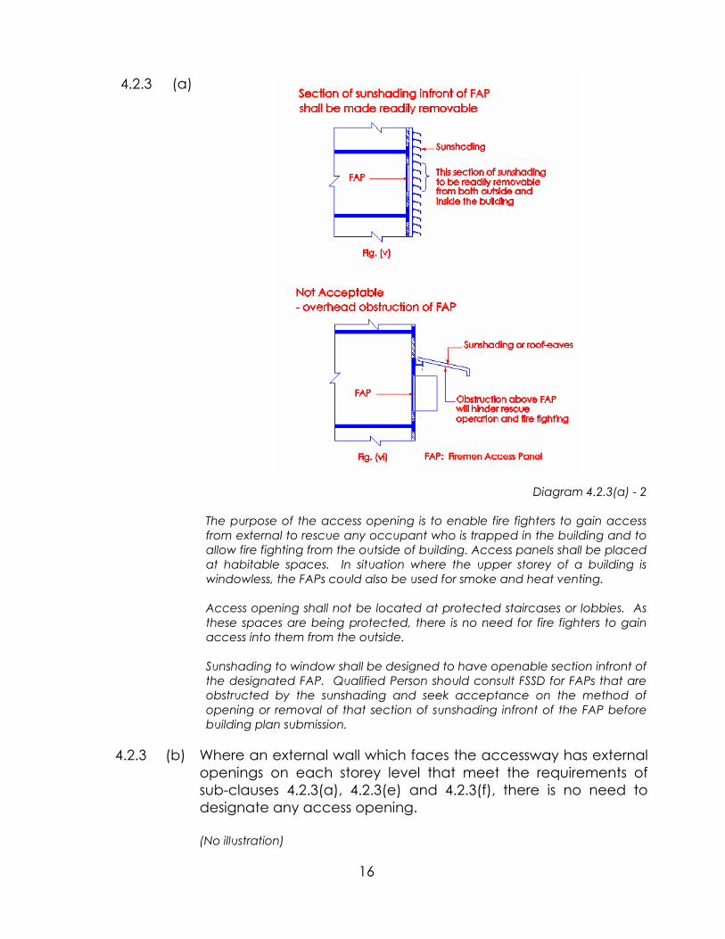
4.2.3 (a)
Diagram 4.2.3(a) - 2
The purpose of the access opening is to enable fire fighters to gain access from external to rescue any occupant who is trapped in the building and to allow fire fighting from the outside of building. Access panels shall be placed at habitable spaces. In situation where the upper storey of a building is windowless, the FAPs could also be used for smoke and heat venting.
Access opening shall not be located at protected staircases or lobbies. As these spaces are being protected, there is no need for fire fighters to gain access into them from the outside.
Sunshading to window shall be designed to have openable section infront of the designated FAP. Qualified Person should consult FSSD for FAPs that are obstructed by the sunshading and seek acceptance on the method of opening or removal of that section of sunshading infront of the FAP before building plan submission.
4.2.3 (b) Where an external wall which faces the accessway has external openings on each storey level that meet the requirements of sub-clauses 4.2.3(a), 4.2.3(e) and 4.2.3(f), there is no need to designate any access opening. (No illustration)

17
(c) An external wall which faces the accessway and is windowless or a blank-wall shall be provided with access openings at each storey level. (No illustration)
(d)
Signage
Panels to access openings shall be posted with either a red or orange triangle of equal sides (minimum 150mm on each side), which can be upright or inverted, on the external side of the wall and with wordings "Fire Fighting Access - Do Not Obstruct" of at least 25 mm height on the internal side.
Diagram 4.2.3(d)
The signage, either in red or orange triangle would help fire fighters on the ground to locate the designated access openings. The triangle can be upright or inverted.
18
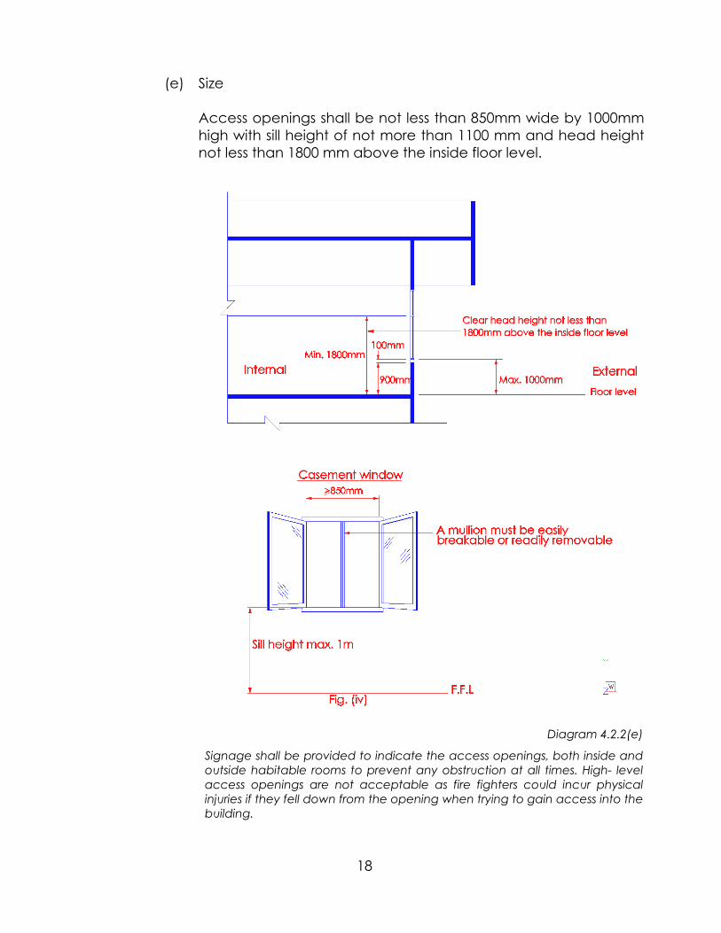
(e) Size
Access openings shall be not less than 850mm wide by 1000mm high with sill height of not more than 1100 mm and head height not less than 1800 mm above the inside floor level.
Diagram 4.2.2(e)
Signage shall be provided to indicate the access openings, both inside and outside habitable rooms to prevent any obstruction at all times. High- level access openings are not acceptable as fire fighters could incur physical injuries if they fell down from the opening when trying to gain access into the building.

19
The sill height of not more than 1100mm is to facilitate the free movement in/out of the building. Higher sill height would pose problems as fire fighter could incur a fall when entering the building and restrict movement.
The minimum width of 850m shall not include a mullion usually found in casement windows. The provision of mullion would reduce the access opening. This would cause difficulties to fire fighters when trying to get into or out of the building, carrying with them equipment or injured occupant.
(f) Number and position of access openings for buildings other than residential:
(i) Buildings other than residential
For buildings under purpose group III exceeding the habitable height of 10m up to 60m, access opening is required at every storey level, other than 1st storey, opening directly onto accessway.
(iii) Position
Access openings shall be spaced at not more than 20m apart measured along the external wall from centre to centre of the access openings.

20
Compartments not accessible from one another
Diagram 4.2.3 (f)(iii) - 2 As the compartments are not accessible from one another, each
compartment shall be provided with at least one access opening. For compartment C, at least 2 access openings are required. Access openings are provided along the external walls overlooking the fire engine accessway.

21
ATRIUM DESIGN
Diagram 4.2.3 (f)(iii) - 3
In situation where void or atrium interferes with the siting of FAPs, for example, FAPs 3 and 4 as shown in the above diagram, the Qualified Persons should consult FSSD to determine the alternative suitable location for the affected FAPs and the adequacy of the overall provision per storey of the building up to 60m habitable height.

22
(iv) For buildings under purpose group III where
an area or space has a ceiling height greater than 10m, additional high level access openings for smoke venting and fire fighting purposes shall be provided and located in the external walls opening into the area or space.
Additional openings
The additional access opening is meant for smoke venting. It is not necessary to provide firemen access panel, as there is no landing below the opening. The additional opening shall be labelled as ‘Smoke Vent’ of not less 25mm height.
(v) In a building with limited external wall and
insufficient provision of accessway or access openings, installation of internal fire fighting facilities such as rising main, sprinkler system, shall be required.
Internal fire fighting provision
Diagram 4.2.3(iv)
>10m

23
Location Plan
In long narrow sites, the provision of fire engine accessway would affect the
layout of the building. To compensate for lack of fire engine accessway, it would be necessary to provide internal fire fighting facilities such as sprinkler system, wet or dry rising mains, fire lift. QP shall obtain waiver approval prior to making building plan submission.
Proposal Plan Diagram 4.2.3(f)(v)

24
4.3 ACCESS TO BUILDINGS WITH RISING MAINS Buildings fitted with rising mains and automatic sprinkler system shall
have fire engine access road for pumping appliances within 18m of the breeching inlet. The breeching inlets shall be visible from the fire engine access road.
Breeching inlets should be visible from fire engine access road to avoid delay in
locating them upon arrival of fire crew. For better control and limit to only one hose length being used, the breeching inlets shall not be sited more than 18m away from the fire engine access road
4.4 PRIVATE FIRE HYDRANT 4.4.1 REQUIREMENTS Private fire hydrant
(a) Every part of a fire engine access road in a private lot shall
be within an unobstructed distance of 50m from a hydrant. Where a public hydrant conforming to such requirement is not available, private hydrant(s) shall be provided (see diagram 4.4.1(a)).
Diagram 4.3

25
The distance of 50m is measured horizontally along the access road.
(b) In situations where more than one private hydrant are
required, the hydrants shall be located along the fire engine accessway such that every part of the fire engine accessway is within an unobstructed distance of 50m from any hydrant (see diagram 4.4.1(b)).
Diagram 4.4.1(a)

26
(b) In situations where more than one private hydrant are required, the hydrants shall be located along the fire engine accessway such that every part of the fire engine accessway is within an unobstructed distance of 50m from any hydrant (see diagram 4.4.1(b)).
( c) Siting and types of fire hydrants shall comply with the requirements stated in SS CP 29: Code of Practice for Fire Hydrant Systems and Hose reels.
Sharing of private hydrants located in neighbouring lot is not acceptable.
Diagram 4.4.1(c) - 1

27
Separation distance between hydrant and low retaining walls/buildings
The required minimum of 6m clearance between the building or retaining
wall/boundary wall and fire hydrant can be reduced to minimum 1000mm. The above relaxation is to allow the minimum working space for hose connection. Please refer to FSSD circular ref: FSSD37/86/FSSD34/86 dated 27 July 99.
Diagram 4.4.1(c) - 2

28
Diagram 4.4.1(c) - 3
Diagram 4.4.1(c) - 4

29
4.4.2 WATER SUPPLY FOR PRIVATE HYDRANT
Provision of water supply for private hydrant system where required by this Code shall comply with either one of the following three requirements:
(a) Where the private hydrants are located not higher than reduced level 125m, they shall be connected to public mains in accordance with SS CP 29.
There is a need to differentiate at RL 125m as public mains located at above RL
125m would not be able to provide the required water pressure. It is important that hydrants annotated in building plan should be given their respective reduced levels. Similarly, the platform level of the building should also be given on plan.
Diagram 4.4.2(a)

30
4.4.2 WATER SUPPLY FOR PRIVATE HYDRANT Provision of water supply for private hydrant system where
required by this Code shall comply with one of the following requirements:
(a) Private fire hydrants installed at reduced level 125 m
and below can receive direct supply from public water mains provided :
(i) The nominal bore of the hydrant pipe and the
bulk water meter shall not be less than 150mm in diameter; and
(ii) The running pressure/flow at the hydraulically
most unfavourable hydrant of the private hydrant system shall comply with the following :
• Running pressure >= 0.9 x (running
pressure of the nearest public hydrant – pressure drop across the bulk water metre); and
• Flow Rate >= 0.9 x water flow of the nearest public hydrant or >= total flow demand (as required in Table 4.4.2) of the private hydrant system, provided the running pressure at the remotest private hydrant is greater than 2 bars.
Note : (i) In calculating the frictional loss for the
private hydrant system, the design flow rates shown in Table 4.4.2 shall be used.
(ii) Pressure drop across bulk water metre shall
not be more than 1bar.

31
Diagram 4.4.2(a)
There is a need to differentiate at RL 125m as public mains located at above RL
125m would not be able to provide the required water pressure. It is important that hydrants annotated in building plan should be given their respective reduced levels. Similarly, the platform level of the building should also be given on plan.
4.4.2 (b) (i) where there is only one private hydrant in the plot that is located above reduced level 125m; and
(ii) this hydrant is not the sole hydrant within 50m from any breeching inlet(s) feeding into fixed water based fire fighting system(s) including automatic sprinkler systems, dry riser systems, and wet riser systems for the building(s) standing on this plot of land;
then this hydrant may be in the form of a "dry" hydrant. A "dry" hydrant shall be connected to a 150mm diameter dry pipe, which shall be connected at the other end to a four-way breeching inlet. This breeching inlet shall be within 18m from any fire engine accessible way and within 50m from any wet hydrant, private or public.

32
Diagram 4.4.2(b)
“Dry” hydrant is equivalent to the provision of dry rising main. Care should be taken to prevent accidental damage by vehicle etc to the horizontal run of the pipe aboveground. The dry pipe should be differently identified on site. The provision of dry hydrant is a relaxation as all hydrants as required to be fed with water at all times. This is allowed as the fire fighters could use other hydrants located below RL 125 which are within 50m from the breeching inlets.

33
4.4.2 (c) Where there are more than one private hydrant that are
located above reduced level 125 m within the same plot, storage and pumping arrangements of water supply to these specified hydrants shall comply with those for wet rising mains stipulated in SS CP 29. The water supply for hydrants serving residential and non-residential developments shall be as follows:
Private hydrants located above reduced
level 125m within the same plot
Type of development
No of hydrant that will be used for fire
fighting
Common water
supply for hydrant
to be used
Stored water supply
1 Residential development
One Not less than 38 l/s at
3.5 bar.
45 min
2 Non-residential development
(based on floor area of the
biggest floor)
a
<1,000m2 Two Not less than 38 l/s at 3.5 bar for
1st hydrant & 19 l/s at 3.5 bar for
2nd hydrant.
45 min
b Every subsequent increase of 1,000m2
of floor area
An additional hydrant
For each subsequent
hydrant, 19 l/s will be added to
the common supply for the
hydrant.
45 min
For non-residential building e.g commercial building, the need may arise to operate more than 3 hydrants.

34
The private hydrants are required to be charged with water all the times so that fire
fighters could use them for feeding the breeching inlets to fixed water based fire fighting systems and for fire fighting purposes.
4.4.2 (c) Where more than one private hydrants are
located above reduced level 125m within the same plot, storage and pumping arrangements of water supply to these specified hydrants shall comply with those for wet rising mains stipulated in SS CP 29 and Table 4.4.2 – Water Supply & Storage Requirements For Private Hydrant. The water supply for hydrants shall be as follows:
Table 4.4.2 – Water Supply & Storage requirements For Private Hydrant
Purpose Group/Requirement
Purpose Group (*) III
Minimum running pressure
2 bars
Diagram 4.4.2(c)

35
Minimum flow rate <1000m² - 38L/s <5000m² - 57L/s <10000m² - 76L/s
(57L/s if sprinkler protected) Additional 19L/s for subsequence 5000 m²
Minimum duration 45 mins * Based on the floor area of the largest compartment in
the building
The private hydrants are required to be charged with water all the times so that fire
fighters could use them for feeding the breeching inlets to fixed water based fire fighting systems and for fire fighting purposes.
4.4.3 Protection of hydrant mains in building
All hydrant mains which pass through a building shall have its full
length within the building encased in masonry. However, in areas considered to be of low fire risk by the Relevant Authority, the mains are allowed to be protected by fire resisting construction, provided the following requirements shall be complied with:
Diagram 4.4.2(c)

36
(a) The protective enclosure to the mains shall have the same fire resistance as the elements of structure of the building where the mains are located;
(b) The hydrant mains shall be located in common circulation areas, such as carparking spaces and driveways; ie they shall not pass through private or confined spaces;
(c) No service (except sprinkler pipes) shall be located above or crossing over the hydrant mains;
(d) The hydrant mains shall be located away from explosion risk area; and
(e) The protective enclosure to the hydrant mains shall be labelled with the words “HYDRANT MAIN” of minimum 50mm height at suitable intervals.
Hydrant main supplying water to hydrant shall be appropriately protected to
prevent any damage arising from fire or mechanical impact from moving objects or the carrying out of addition/alteration works within the building. Watermain, which is damaged, would affect the water supply to the hydrant. This would in turn affect the fire fighting operation in an emergency. Hydrant main protected with dry protection e.g. boxed-up with fire rated boards or sprayed on materials shall only be allowed to be routed or located in basement or floor protected by sprinkler system.
Diagram 4.4.3

37
Amended clause 4.4.3 in Fire Code 2002 4.4.3 All hydrant mains which pass through a building shall have
its full length within the building protected with fire resistance construction complying with cl.3.8.7 (c) of at least the same fire resistance as the element of structure, provided the following requirements are complied with :
Protection of hydrant mains in buildings
(a) The hydrant mains shall be located in common circulation areas, such as carparking spaces and driveways; ie they shall not pass through private or confined spaces;
(b) No services (except sprinkler pipes) shall be
located above or crossing over the hydrant mains;
(c) The hydrant mains shall be located away from
explosion risk areas; and
(d) The protective enclosure to the hydrant mains
shall be labelled with the words “HYDRANT MAIN” of minimum 50mm height at suitable intervals.
Hydrant main enclosed In masonry or located In masonry trench
Hydrant main boxed-up with fire rated boards
or sprayed-on material
Hydrant main

38
Hydrant main supplying water to hydrant shall be appropriately protected to prevent any damage arising from or the carrying out of addition/alteration works within the building. Watermain, which is damaged, would affect the water supply to the hydrant. This would in turn affect the fire fighting operation in an emergency. Hydrant main traversing the basement car parking areas can be protected in the following manner, a hydrant mains can be laid in a concrete trench forming part of the concrete floor
over basement; or b hydrant mains can be boxed up with fire rated board or protected with spray-on fire
rated material, if the mains are exposed under the concrete slab over the basement.