Embed Size (px)
Citation preview

4-i
CHAPTER 4 ROOF AND PROPERTY DRAINAGE
4.1 INTRODUCTION ................................................................................................................. 4-1
4.2 ROOF DRAINAGE SYSTEM .............................................................................................. 4-1
4.3 ROOF DRAINAGE DESIGN PROCEDURE .................................................................... 4-2 4.3.1 Catchment Area ...................................................................................................... 4-2 4.3.2 Design Average Recurrence Intervals ................................................................ 4-2 4.3.3 Discharge Estimation ............................................................................................ 4-2 4.3.4 Design of Eaves Gutters and Downpipes .......................................................... 4-4 4.3.5 Design of Valley Gutters ....................................................................................... 4-5 4.3.6 Design of Box Gutters and Downpipes .............................................................. 4-6
4.4 PROPERTY DRAINAGE ..................................................................................................... 4-8 4.4.1 General ..................................................................................................................... 4-8 4.4.2 Design Average Recurrence Intervals ................................................................ 4-9 4.4.3 Drainage to the Rear of Properties ...................................................................... 4-9 4.4.4 Drainage on Hillside Area .................................................................................... 4-9 4.4.5 Drainage through Public Reserves ...................................................................... 4-10 4.4.6 Rainwater Harvesting and Detention ................................................................ 4-10
REFERENCES ...................................................................................................................................... 4-11
APPENDIX 4.A DESIGN CHARTS .............................................................................................. 4-13
APPENDIX 4.B EXAMPLE – EAVES GUTTERS ........................................................................ 4-17
APPENDIX 4.C EXAMPLE – BOX GUTTERS ............................................................................. 4-19

Roof and Property Drainage 4-1
4.1 INTRODUCTION
Property drainage refers to the systems that transfer runoff from roofs, paved areas and other surfaces of a premise to a suitable outlet or disposal facility. The system involves gutters, downpipes, drains, pipes, swales and storage and treatment facilities. Typical property drainage components for residential and industrial premises are shown in Figure 4.1.
Local authorities may place limitations on the amount of stormwater that can be drained to streets or trunk drainage systems, in order to reduce flooding and pollution. In these cases it is the responsibility of the property owner to provide infiltration or on-site detention facilities.
OverflowDownpipe
Pit
Inter-allotment
Downpipe
Eaves Gutter
Sump andInternal
Subsoil Drain
Street Pit
Street Drain StreetOverland FlowPipe
Rainhead
Box Gutter
Eaves Gutter
DownpipeDrain
Valley
Industry
Gutter
House
Figure 4.1: Typical Property Drainage Components
4.2 ROOF DRAINAGE SYSTEM
Roof drainage systems are located at the top of property drainage systems. Because the areas are usually small and there are fewer complications, roof drainage can be designed using simpler methods than those employed at larger scale drainage. This chapter applies to those buildings where roof drainage is specified for reasons of runoff conveyance and collection to storage/detention facilities as well as for comfort and safety of occupants and the protection of the building structure. The rules also apply to all inhabited buildings as well as industrial buildings and warehouses.
The methods given in this section are based on the Australian/ New Zealand Standard (AS/NZS 3500.3, 2003), adapted for Malaysian conditions. Eaves gutters are located on the outside of a building while box gutters and valley gutters are located within the plan area of the building and the intersecting sloping surfaces of a roof respectively (Figure 4.2).
a) Eaves b) Box Figure 4.2: Roof Gutters

4-2 Roof and Property Drainage
4.3 ROOF DRAINAGE DESIGN PROCEDURE
4.3.1 Catchment Area
The design approach for drainage of roofs is to determine the layouts and sizes of components, and then to analyse their behaviour in one or more design storms that will test the adequacy of the system.
The design procedure herein follows AS/NZS 3500.3 in recognising that wind causes the rain to slope, creating a horizontal component of rainfall, which becomes significant on vertical walls or sloping roofs. The direction of wind that results in the maximum roof catchment area should be selected. It is not sufficient to consider only the direction of prevailing winds. A maximum rainfall slope of 2 vertical to 1 horizontal is assumed. The roof catchment area (Ac) estimates, based on Figure 4.3, are given below:
For single sloping roof fully exposed to wind
2A
AA vhc += (4.1)
where the meaning of terms is as shown in Figure 4.3. If the roof is partly shielded by another wall, the net vertical area Av is the area seen by looking in the same direction as the wind. The following formula is used
)Α-(Α21
+Α=Α 12 vvhc (4.2)
For the two adjacent sloping roofs
)A-(A21
+A+A=A 1221 vvhhc (4.3)
Roofs of larger buildings may have complex arrangements of catchments and drainage systems. Where it is difficult to define catchments, a conservative approach should be adopted, assuming the largest possible catchments.
4.3.2 Design Average Recurrence Intervals
Roof drainage shall use the ARIs set out in Table 4.1. The critical storm duration of 5 minutes should be adopted for all roofs unless special circumstances justify a longer duration.
Table 4.1: Design ARIs for Roof Drainage
Property Type Eaves Gutters Valley and Box Gutters
All buildings 20 year ARI 100 year ARI Notes :
1. If water can flow back into the building, then overflow measures are required 2. A higher design ARI shall be adopted for buildings located on hillside area
4.3.3 Discharge Estimation
The 5 minute duration 20, 50 and 100 year ARI rainfall intensities for the particular location are obtained from the short-duration rainfall IDF method in Chapter 2, applied at the particular site. If special circumstances justify the use of a longer time of concentration, the rainfall intensity for this time of concentration shall be derived using the methods set out in Chapter 2.

Roof and Property Drainage 4-3
21
(a) Single Sloping Roof Freely Exposed to the Wind
21
(b) Single Sloping Roof Partially Exposed to the Wind
(c) Two Adjacent Sloping Roofs
Angle of Descent of Rain
1
Av
2
Av
AvAh
Ah
Av
Av
2
21
Roof
Roof
Roof
Angle of Descent of Rain
Ao
Av1
2
1Ah Ah
1
2
Figure 4.3: Sloped Roof Catchment Area Relationships
4-4 Roof and Property Drainage
The roof flow produced by the design rainfall shall be calculated using the Rational Method, with runoff coefficient C = 1.0, which can be expressed by the following form:
3600= cA.i
Q (4.4)
where, Q = Peak flow (L/s); i = Rainfall intensity (mm/hr); and Ac = Roof catchment area draining to a downpipe (m2).
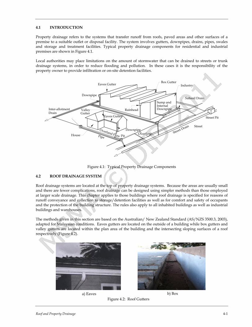
4.3.4 Design of Eaves Gutters and Downpipes
For a simple sloping (gabled) roof, the eaves gutter (Figure 4.4) should slope from one end to the downpipe location at the other end.
Shingles
Panel installed undertop layer of shingle
Fascia board
Soffit
Gutter
Downpipe
Figure 4.4: Cross Section of Eaves Gutter
The procedure for the design of an eaves gutter is as follows:
• Determine the catchment area to each downpipe; • Determine the design 5 minute duration, 20 year ARI rainfall intensity; and • Choose the gutter size from Design Chart 4.A1.
To provide adequate fall and minimise the risk of ponding, the minimum gradient of an eaves gutter shall be 1:500.
The minimum cross-sectional size of an eaves gutter shall be 4,000mm2 while the normal maximum 22,000mm2. If calculations indicate that a larger size is required, it is preferable to provide more downpipes rather than increasing the gutter size.
The required size of eaves gutter shall be determined from Design Chart 4.A1. This Chart is derived from Manning's formula with 'n' = 0.016 and S = 1/500. This is a simplified method because the effect of varying flow depth is neglected. When applying the design chart, Ac is the catchment area draining to a single downpipe.
Downpipe size is then determined from Table 4.2 to match the eaves gutter size. Downpipes may be either rectangular or circular. Note that for a given roof catchment area, the size of downpipe will be the same irrespective of the slope of the eaves gutter.
If the listed size is not available, an alternative downpipe with equal or greater cross-sectional area than that shown may be substituted.

Roof and Property Drainage 4-5
Table 4.2: Required Size of Downpipe for Eaves Gutter (AS/NZS 3500.3, 2003)
Eaves Gutter Size (mm2)
Minimum Nominal Size of Downpipe (mm)
Circular Rectangular
4,000
75
4,200 65 x 50
4,600
4,800 85
75 x 50
5,900
6,400 90
100 x 50
6,600
6,700 100
75 x 70
8,200
9,600 125
100 x 75
12,800 100 x 100
16,000 150
125 x 100
18,400
19,200 150 x 100
20,000 Not applicable 125 x 125
22,000 150 x 125
4.3.5 Design of Valley Gutters
Valley gutters are located between the sloping roof sections of a hipped roof (see Figure 4.1). The following points should be noted when designing systems incorporating valley gutters:
• Valley gutters should end at the high point of an eaves gutter; and • The discharge from a valley gutter does not flow equally into both eaves gutters. Therefore the designer
should allow at least 20% excess capacity in the sizing of the eaves gutters.
The profile of a valley gutter is shown in Figure 4.5.
We
heSide Angle
hf
Figure 4.5: Profile of a Valley Gutter
The sizing guidelines in Table 4.3 are valid for the following conditions:
• Roof slope of not less than 12.5°; • The nominal side angle of valley gutters is 16.5°; and
4-6 Roof and Property Drainage
Gutter BoardsRoof Framing
Box Gutter
High Point
RoofingMaterial
RoofingBatten
• The catchment area shall not exceed 20m2.
The procedure for the design of a valley gutter is as follows:
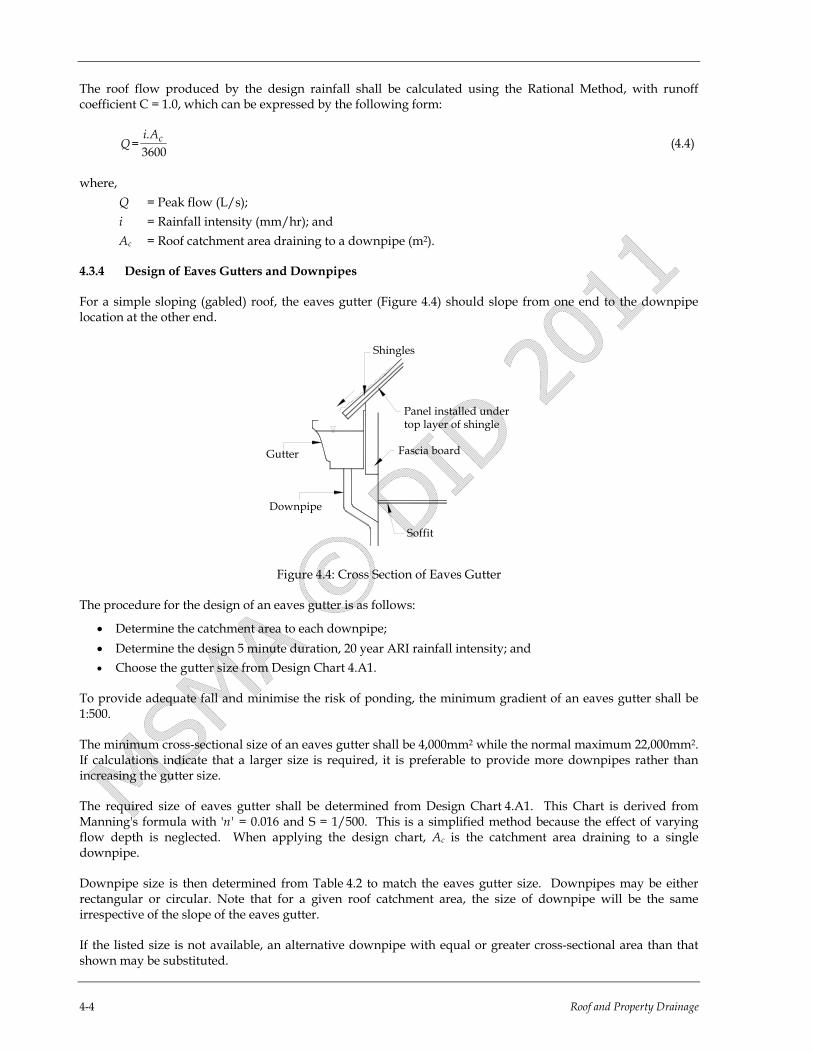
• Select the ARI; • Determine the design 5 minute duration, 100 year ARI rainfall intensity; and • Choose the girth size and dimensions from Table 4.3.
Table 4.3: Minimum Dimensions for Valley Gutters
Design Rainfall Intensity (mm/hr)
Minimum Dimension (mm) Sheet Width
Effective Depth (he)
Effective Width (We)
≤ 200 355 32 215
201 - 250 375 35 234
251 - 300 395 38 254
301 - 350 415 40 273
351 - 400 435 43 292
> 400 455 45 311 Notes:
1. Freeboard (hf) = 15 mm 2. The sheet width from which the valley is to be formed
has been calculated on the basis of hf = 15 mm and an allowance for side rolls or bends of 25 mm.
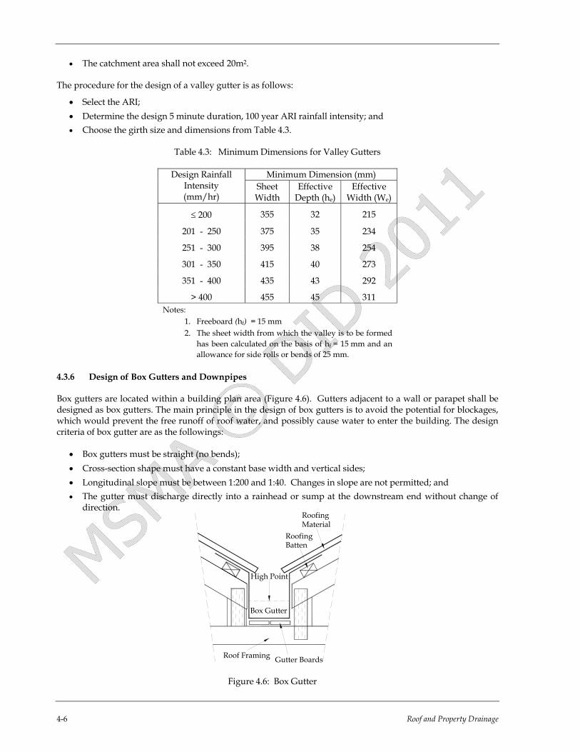
4.3.6 Design of Box Gutters and Downpipes
Box gutters are located within a building plan area (Figure 4.6). Gutters adjacent to a wall or parapet shall be designed as box gutters. The main principle in the design of box gutters is to avoid the potential for blockages, which would prevent the free runoff of roof water, and possibly cause water to enter the building. The design criteria of box gutter are as the followings:
• Box gutters must be straight (no bends); • Cross-section shape must have a constant base width and vertical sides; • Longitudinal slope must be between 1:200 and 1:40. Changes in slope are not permitted; and • The gutter must discharge directly into a rainhead or sump at the downstream end without change of
direction.
Figure 4.6: Box Gutter

Roof anf Property Drainage 4-7
Box gutters are connected to either rainheads or sumps with overflow devices. The minimum width of box gutters for commercial or industrial construction is 300mm. For residential construction, a minimum width of 200 mm is permitted but such gutters are more prone to blockage and should be subject to more frequent inspection and maintenance.
The procedure for design of a box gutter is as follows:
• Determine the catchment area draining to each downpipe (Equation 4.1); • Determine the design 5 minute duration, 100 year ARI rainfall intensity; • Select the width and slope of the box gutter to suit the building layout; and • Read off the minimum depth of the box gutter from Design Chart 4.A3. This minimum depth must be
used for the full length of the box gutter. If a sloping box gutter is built with a horizontal top edge for architectural reasons, the minimum depth requirement still applies. When applying the design chart, the catchment area obtained is for draining to a single downpipe.
4.3.6.1 Rainheads and Downpipes
Box gutters shall discharge via a rainhead or sump, to a downpipe. The required size of downpipe from a box gutter is determined from Design Chart 4.A3 (AS/NZS 3500.3, 2003). The sizing principle is to limit the maximum capacity of the downpipe in order to prevent slugs of unstable flow. The graph does not permit very deep, or very shallow rainheads. The minimum depth of water in the rainhead is limited to about half of the diameter of the downpipe. Above this depth, orifice flow conditions apply. A standard rainhead is shown in Figure 4.7. It includes an overflow to safely discharge flow from the box gutter even if the downpipe is blocked. The design flow of a rainhead shall not exceed 16 L/s.
r
r
r
a
h -25
L
h
hRainhead
Downpipe
Box Gutter
Overflow
Figure 4.7: Typical Rainhead
Also designers are to observe the followings:-
• Width of rainhead is equal to the width of box gutter. The rainhead must be sealed to the box gutter; • The depth of a rainhead, hr must be at least 1.25 x equivalent diameter of a rectangular downpipe (hr≥
1.25De) or 1.25 x internal diameter of a circular downpipe (hr≥ 1.25Di). • There is an overflow weir at a lower level than the sole of the box gutter; and • The rainhead to be fully seated to the box gutter and the front of the rainhead left open above the overflow
weir.
4.3.6.2 Sumps
Sumps are located at the low point of a box gutter, which slopes towards the sump in both directions. A standard sump is shown in Figure 4.8. All sumps must be provided with an overflow to prevent overtopping of the box gutter even if the downpipe is blocked. Two types of overflow devices are permitted for use

4-8 Roof and Property Drainage
a) Side Overflow Device
This device is shown in Figure 4.8. This design has been in use world-wide for many years. It is only suitable for box gutters, which run parallel and adjacent to a parapet wall.
Downpipe
Overflow Duct or Channel
Wall
Sump
Box Gutter
Figure 4.8: Typical Sump and Side Overflow
b) High Capacity Overflow Device
As shown in Figure 4.9 this device design is developed in Australia (Jones and Kloti, 1999). It is anticipated that further research will be conducted into developing overflow devices suitable for Malaysian conditions.
Box Gutter
OverflowDownpipe
Normal Downpipe
Sump
OverflowChannel
Secondary SumpOverflow Weirs
Figure 4.9: Sump with Alternative Overflow Devices
4.4 PROPERTY DRAINAGE
4.4.1 General
The drainage system proposed within allotments depends upon the topography, the importance of the development and the consequences of failure. The drainage systems collect water from roofs (via downpipes), surfaces of areas around buildings, and flows onto the property from adjacent allotments in major storm.
In areas with suitable soils and water table conditions, stormwater may be infiltrated directly into the soil, rather being directed to the street drainage system (Chapter 8).

Roof and Property Drainage 4-9
4.4.2 Design Average Recurrence Intervals
Elements in the property drainage systems shall be designed to contain flows from minor storm events of ARI not less than that specified in Table 4.4.
The property drainage systems shall be designed to ensure that overflows in a major storm event do not present a hazard to people or cause significant damage to property.
Table 4.4: Minimum Design ARIs for Property Drainage
Effect of Surcharge and Overland Flow ARI
(years)
Small impact, in low density area 1
Normal impacts 2 Ponding in flat topography; or flooding of parking lots to depths greater than 150 mm
10
Impeded access to commercial and industrial building 10 Ponding against adjoining buildings; or impeded access to institutional or important buildings (e.g., hospitals, halls, school entrances)
20
4.4.3 Drainage to the Rear of Properties
Where the natural ground level does not permit drainage by gravity to the street drain or gutter, it will be necessary to either fill the site to obtain a fall to the street, or alternatively, to provide a piped drain through an adjoining private property or properties, to discharge the runoff from the site by gravity.
Requirements for piped drainage in privately owned lots are set out in Chapter 15. Open drains shall not be permitted at the rear of private lots because they are difficult to maintain.
Any piped drain in private property, which serves an adjoining property, shall be protected by a drainage easement. Such easements shall be free of any building encroachments, including eaves footing and shall contain a single pipe only. Full details of any proposed easement is to be submitted to the regulatory authority for approval and this easement shall be registered with the authority prior to release of the building plans.
4.4.4 Drainage on Hillside Area
In common practice, although the roofs of buildings are designed to collect storm water, there is no provision to effectively drain them to the perimeter drain surrounding the buildings. The concentrated runoff from the roof eaves is sometimes much higher than the direct impact due to rainwater and this can cause ground erosion.
Buildings in which roof gutters are omitted shall not be permitted in hillside areas. This type of roof drainage would have unacceptable consequences in term of concentrated runoff on potentially unstable hill slopes.
The 20 year ARI standard for roof eaves gutters (Table 4.1) should be increased to 50 year ARI in hillside areas. The standard for box gutters is governed by other factors, and does not change.
Properly designed gutters must be provided to collect stormwater from the roof and convey it to the formal property drainage system, either open drains or pipes. As a general principle, it is desirable to directly connect all significant impervious areas to the lined drainage system.
Property drainage shall be installed at or below ground level, to maximise the interception of surface runoff. The creation of ponding areas due to poor grading of property drainage is not permitted.

4-10 Roof and Property Drainage
4.4.5 Drainage through Public Reserves
Where a low level property adjoins a public reserve, the construction of drainage line through the reserve generally will not be permitted and alternative methods of drainage should be investigated, including:
• construction of a pipeline through an adjoining private property; and • a pump out system.
Construction of a drainage line through a public reserve may be permitted by the regulatory authority, only in situations where the applicant provides satisfactory proof that the alternatives have been investigated and found to be impractical.
Where drainage through a public reserve is permitted, the applicant is required to enter into a licence agreement with the regulatory authority, subject to the payment of a one off licence fee under the respective agreement covering any installation, legal or other costs associated with the preparation and execution of the licence agreements, together with an amount considered appropriate towards the improvement of the respective reserve.
Pipes on public streets and land that drain developments are permitted, provided that they are built to the approval authority’s standards and ownership is transferred to the authority. It is not permitted where the proposed drainage system will cause a conflict with other drainage systems or services.
4.4.6 Rainwater Harvesting and Detention
Rainwater tanks may be provided to collect flow from roof and gutter systems. These tanks can be used to:
• provide water supplies; and/or • provide on-site detention storage.
The design of rainwater tanks for water supply is covered in Chapter 6 while the design of on-site detention storage in Chapter 5. Note that any tank volume provided for detention is additional to that set aside for water supply storage.

Roof and Property Drainage 4-11
REFERENCES
1. AS/NZS 3500.3 (2003). National Plumbing and Drainage Code Part 3: Stormwater Drainage – Acceptable Solutions. Published jointly by Standards Australia and Standards New Zealand.
2. Jones and Klöti (1999). High Capacity Overflow Device for Internal Box Gutters of Roofs. 8th International
Conference on Urban Stormwater Drainage (ICUSD), Sydney, Australia.


Roof and Property Drainage 4-13
100.0
90.0
80.0
70.0
60.0
50.0
40.0
30.0
20.0
10.0
03 4 5 6 7 8 9 10 11 12 13 14 15 16 17 18
Design Rainfall Intensity(20I5) or (10I10), mm/hr (Typical)
50 60
70
80 9010
0
120
140
160
180
200
225
250
300
350
400
450
500
Effective Cross-Sectional Area of Eaves Gutter, 1000 mm²for Gradients of 1:500 and Steeper
0.6 1.0 2.0 3.0 4.0 6.05.0
Cat
chm
ent A
rea
Per V
ertic
al D
ownp
ipe
(m²)
Total Flow in Eaves Gutter (L/s)
275
APPENDIX 4.A DESIGN CHARTS
Design Chart 4.A1: Sizing Eaves Gutters for Gradients 1:500 and Steeper
Notes:
1. This graph assumes –
(a) An effective width to depth ratio is about 2:1;
(b) A gradient in the direction of flow is 1:500 or steeper;
(c) The least favourable positioning of the downpipe and bends within the gutter length;
(d) A cross –section of half round, quad, ogee or square; and
(e) The outlet to a vertical downpipe is located centrally in the sole of the eaves gutter.
2. The required eaves gutter discharge areas do not allow for loss of waterway due to internal brackets.

4-14 Roof and Property Drainage
Total Flow in Eaves Gutter (L/s)
100.0
90.0
80.0
70.0
60.0
50.0
40.0
30.0
20.0
10.0
0
Cat
chm
ent A
rea
Per V
ertic
al D
ownp
ipe
(m²)
50 6070
80 9010
0
120
140
160
180
200
225
250
300
350
400
450
500
Design Rainfall Intensity(20I5) or (10I10), mm/hr (Typical)
4 5 6 7 8 9 10 11 12 13 14 15 16 17 18 19 20 21 22 23 24
Effective Cross-Section Area of Eaves Gutter, 1000 mm²for Gradients Flatter Than 1:500
0.6 1.0 2.0 3.0 4.0 6.05.0
275
Design Chart 4.A2: Sizing Eaves Gutters for Gradients Flatter than 1:500
Notes:
1. This graph assumes-
(a) An effective width to depth is a ratio of about 2:1;
(b) A gradient in the direction of flow flatter than 1:500;
(c) The least favourable positioning of the downpipe and bends within the gutter length;
(d) A cross –section or half round, quad, ogee or square; and
(e) The outlet to a vertical downpipe is located centrally in the sole of the eaves gutter.
2. The required eaves gutter discharge areas do not allow for loss of waterway due to internal brackets.

Roof and Property Drainage 4-15
200130150170
80
100
120
140
160
180
617090110 5432 87
61 5432 87 14131211109 15 16
170 150 130 110 90
400
360
320
280
240
200
160
120
80
40
9 10 11 12 13 14 15 16
400
360
320
280
240
200
160
120
80
40
80
100
120
140
160
180
200C
atch
men
t Are
a pe
r Fr
eebo
ard
with
out S
lope
Adj
ustm
ent (
mm
)
Free
boar
d (
) w
ithou
t Slo
pe A
djus
tmen
t (m
m)
Min
imum
Dep
th o
f Box
Gut
ter I
nclu
ding
Minimum Depth of Box Gutter Discharging to RainheadIncluding Freeboard (h ) withSlope Adjustment (mm)
a
Minimum Depth of Box Gutter
Including Freeboard ( ) withDischarging to Rainhead
Slope Adjustment (mm)a
Design Flow (L/s)
50
100
150
200
250
300
350400450500
A
600525450375
300
200
B
1 : 2
001
: 150
1 : 1
001
: 40
C
- Gradient of box gutter (typical)
- Design rainfall intensity ( ) or ( ) in mm/hr (typical)- Width of box gutter in mm (typical)
ABC
LEGEND :
Design Flow (L/s)
Cat
chm
ent A
rea
per
h
100I550I10
Dow
npip
e (m
²)
Dow
npip
e (m
²)
h a
Min
imum
Dep
th o
f Gut
ter,
(ha)
incl
udin
g
Design Chart 4.A3: Sizing a Freely Discharging Box Gutter

4-16 Roof and Property Drainage
Total Depth ofBox Gutter (h ) ata
3
20406080100
120
140
160
180
200
220
240
260
280
300
320
340
360
380
400
420
4
5
6
7
8
9
10
11
12
13
14
15
16
80
120
160
200
240
280
020406080100
120
140
160
180
200
220
240
260
100
140
180
220
260
300
Des
ign
Flow
(L/s
)
Required Depth of Water in Rainhead (mm)
Freeboard (Typical)1 : 200 Slope Including
0
170mm150mm
125mm
100mm
150mm
x 150mm
150mm
Ø
125mm
x 125mm
and 140mm Ø
150mm
x 100mm
125mm Ø
100mm x 100mm
100mm Ø 90mm Ø
100mm x 75mm
Nominal Size of Downpipe, mm (Typical)
440
Total Depth of Rainhead, hr (mm)
Leng
th o
f Rai
nhea
d, L
r (m
m)
60
Design Chart 4.A4: Sizing Downpipes from Box Gutters

Roof and Property Drainage 4-17
APPENDIX 4.B EXAMPLE – EAVES GUTTERS
Problem:
A house, with the gable roof shown in Figure 4.B1, is located in Kuala Lumpur. Determine the size of the required eaves gutters and downpipes.
7.0m
6.5m
13.0m
6.5m
4.0m
4.0m Eaves Gutter(Typical)
Downpipe
Downpipe
Downpipe
Ridge
PLAN
ELEVATION
A
H
G F
J
ED
C
B
Roof Slope14° or 1:4Typical
3.0m
8.0m 3.0m
Figure 4.B1: Gable Roof of a House
Solution:
Reference Calculation Output
a) Calculate rainfall intensity for 5 minutes storm duration and 20 year ARI for Kuala Lumpur.
η
κ
θλ
)( +=
dTi
λ = 69.650
K = 0.151
θ = 0.223
η = 0.880
d = 0.0883
880.0
151.0
)223.00833.0()20)(650.69(
+=
=
304.4
mm/hr
Equation 2.2
Appendix 2.B1
i

4-18 Roof and Property Drainage
Reference Calculation Output b) Calculation of Catchment Area
Equation 4.1 Roof A-B-C-H-A: Plan area Ah = 13 x 4 = 52m2
Rise is 1 m. Vertical area Av = 1 x 13 = 13m2
Total catchment area = Ah + Av/2 = 52 + (13)/2 = 58.5m2
Equation 4.1 Roof J-C-D-E-J: Plan area Ah = 7 x 6.5 = 45.5m2
Rise is 1.75 m. Vertical area Av = 1.75 x 6.5 = 11.4m2
Total Catchment area = Ah + Av/2 = 45.4 + (11.4)/2 = 51.2m2
Equation 4.1 Roof H-J-F-G-H: Plan area Ah = 4 x 6.5 = 26m2 Rise is 1m. Vertical area Av = 1 x 6.5 = 6.5m2 Total catchment area = Ah + Av/2 = 26+(6.5/2) = 29.3m2 c) Calculation of Gutter and Downpipe Size Assume gradient of eaves gutter is 1:600 Roof A-B-C-H-A: Catchment area = 58.5m2 Chart 4.A2 Required effective cross section area for gutter A-B = 19,500mm2 The value of effective cross section area for gutter A-B exceeded the
maximum value of cross section for circular downpipe. Therefore, the square downpipe is chosen.
Table 4.2 Required downpipe size = 125mm x 125mm
Roof J-C-D-E-J: Catchment area = 51.2m2 Chart 4.A2 Required effective cross section area for gutter E-D = 17,250mm2 Table 4.2 Required downpipe size = 150mm Ø Roof H-J-F-G-H: Catchment area = 29.3m2 Chart 4.A2 Required effective cross section area for gutter F-G = 11,000mm2 Table 4.2 Required downpipe size = 125mm Ø
Roof and Property Drainage 4-19
4.4m
7.25m
7.25m
Wall
Rainhead
Downpipe
1.5m
9m
RidgeBox GutterExpansion Joint
16
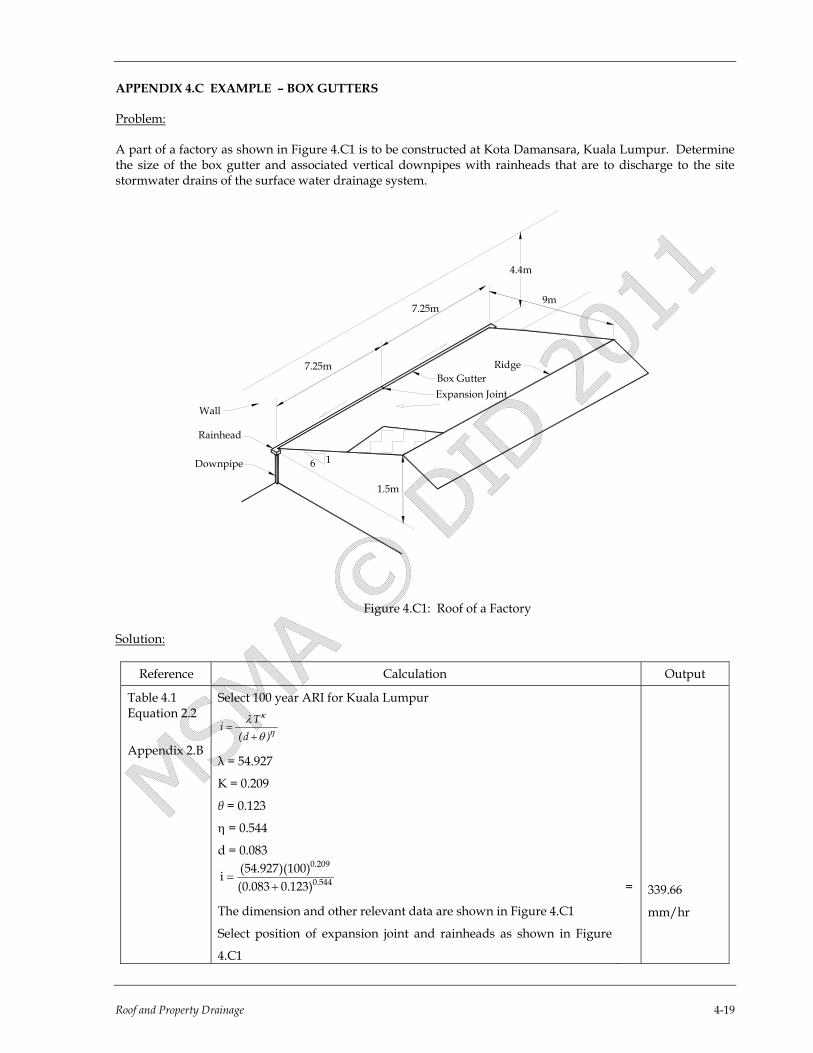
APPENDIX 4.C EXAMPLE – BOX GUTTERS
Problem:
A part of a factory as shown in Figure 4.C1 is to be constructed at Kota Damansara, Kuala Lumpur. Determine the size of the box gutter and associated vertical downpipes with rainheads that are to discharge to the site stormwater drains of the surface water drainage system.
Figure 4.C1: Roof of a Factory
Solution:
Reference Calculation Output
Table 4.1 Equation 2.2
Appendix 2.B
Select 100 year ARI for Kuala Lumpur
η
κ
θλ
)d(Ti+
=
λ = 54.927
K = 0.209
θ = 0.123
η = 0.544
d = 0.083
445.0
209.0
)123.0083.0()100)(927.54(i
+=
The dimension and other relevant data are shown in Figure 4.C1
Select position of expansion joint and rainheads as shown in Figure
4.C1
=
339.66
mm/hr

4-20 Roof and Property Drainage
Reference Calculation Output
Equation 4.2
Chart 4.A3
Chart 4.A3
Chart 4.A3
Chart 4.A4 Chart 4.A4
Chart 4.A4
Calculate catchment area
Roof Ah = 7.25m x 9m
Roof Slope 1:6, Rise = 1/6 x 9
Roof Av1 = 7.25m x 1.5m
Wall Av2 = 7.25m x 4.4m
Ac = Ah + 1/2 (Av2 – Av1)
Ac = 65.25m2 + 1/2 (31.9 – 10.88) m2
Q = 7 L/s
Q < 16 L/s0
For Q = 7 L/s, select sole width of box gutter (Wbg) = 375mm and
gradient = 1:200
For Q = 7 L/s, Wbg = 375mm and gradient = 1:200 , the actual minimum
depth of box gutter including free board (ha)
As each box gutter discharges to a rainhead that is design to divert the design flow away from the building in the event of a total blockages of the downpipe, without increasing the depth of flow in the box gutter, this is the minimum depth required for the box gutter.
The design flow in each box gutter is also the design flow in the rainhead, Q = 7 L/s.
Select 100 mm diameter downpipe. Depth of water in rainhead Total depth of rainhead hr
Alternatively, select 100mm x 75mm downpipe. Depth of water in rainhead Total depth of rainhead Use total depth of rainhead
Check if the total depth hr needs to be adjusted as required by notes in Figure 4.7.
For 115 mm depth of box gutter, length of rainhead (Lr) Depth of rainhead
Refer to Figure 4.7, final dimension of rainhead, hr = 250 mm, hr – 25 ha Lr
=
=
=
=
=
=
= =
= = =
= =
= = =
65.25m2
1.5m
10.88m2
31.9m2
75.76m2
115mm Use box gutters 375 mm x 115 mm minimum with gradient 1:200
125mm 205mm
140mm 235mm 250mm
150mm 250mm
225mm 115mm 150mm