Embed Size (px)
Citation preview
Network Layer 41
Chapter 4Network Layer
A note on the use of these ppt slides:We’re making these slides freely available to all (faculty, students, readers). They’re in PowerPoint form so you can add, modify, and delete slides (including this one) and slide content to suit your needs. They obviously represent a lot of work on our part. In return for use, we only ask the following: If you use these slides (e.g., in a class) in substantially unaltered form, that you mention their source (after all, we’d like people to use our book!) If you post any slides in substantially unaltered form on a www site, that you note that they are adapted from (or perhaps identical to) our slides, and note our copyright of this material.
Thanks and enjoy! JFK/KWR
All material copyright 1996-2009J.F Kurose and K.W. Ross, All Rights Reserved
Computer Networking: A Top Down Approach 5th edition. Jim Kurose, Keith RossAddisonWesley, April 2009.
Network Layer 42
Chapter 4: Network Layer
Chapter goals: ❒ understand principles behind network layer services:
❍ network layer service models❍ forwarding versus routing❍ how a router works❍ routing (path selection)❍ dealing with scale❍ advanced topics: IPv6, mobility
❒ instantiation, implementation in the Internet
Network Layer 43
Chapter 4: Network Layer
❒ 4. 1 Introduction❒ 4.2 Virtual circuit and
datagram networks❒ 4.3 What’s inside a router❒ 4.4 IP: Internet Protocol
❍ Datagram format❍ IPv4 addressing❍ ICMP❍ IPv6
❒ 4.5 Routing algorithms❍ Link state❍ Distance Vector❍ Hierarchical routing
❒ 4.6 Routing in the Internet❍ RIP❍ OSPF❍ BGP
❒ 4.7 Broadcast and multicast routing
Network Layer 44
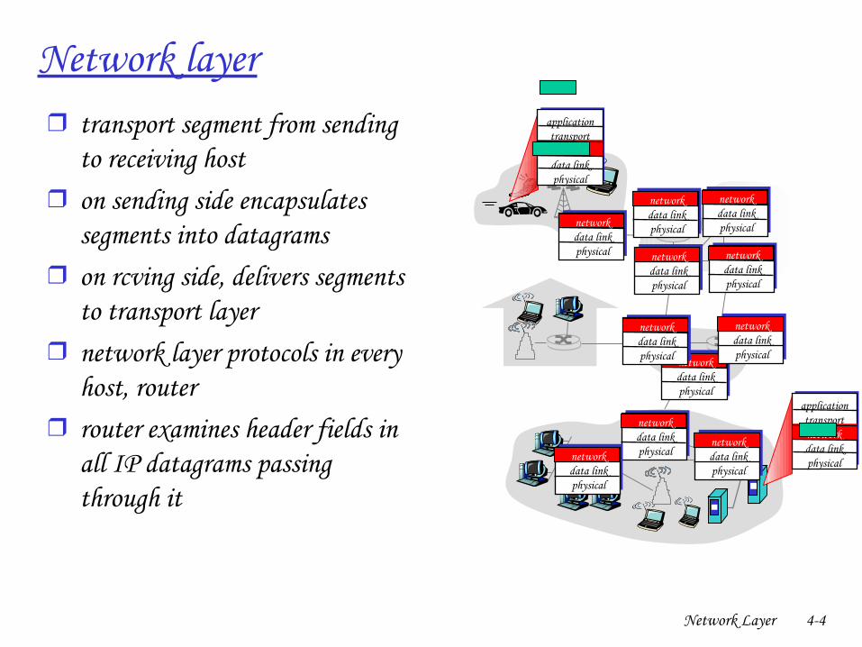
Network layer❒ transport segment from sending
to receiving host ❒ on sending side encapsulates
segments into datagrams❒ on rcving side, delivers segments
to transport layer❒ network layer protocols in every
host, router❒ router examines header fields in
all IP datagrams passing through it
applicationtransportnetworkdata linkphysical
applicationtransportnetworkdata linkphysical
networkdata linkphysical network
data linkphysical
networkdata linkphysical
networkdata linkphysical
networkdata linkphysical
networkdata linkphysical
networkdata linkphysical
networkdata linkphysical
networkdata linkphysical
networkdata linkphysicalnetwork
data linkphysical
Network Layer 45
Two Key NetworkLayer Functions
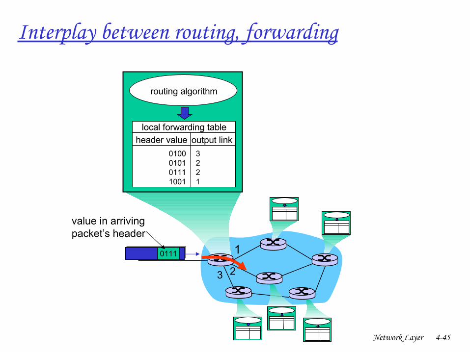
❒ forwarding: move packets from router’s input to appropriate router output
❒ routing: determine route taken by packets from source to dest.
❍ routing algorithms
analogy:
❒ routing: process of planning trip from source to dest
❒ forwarding: process of getting through single interchange
Network Layer 46
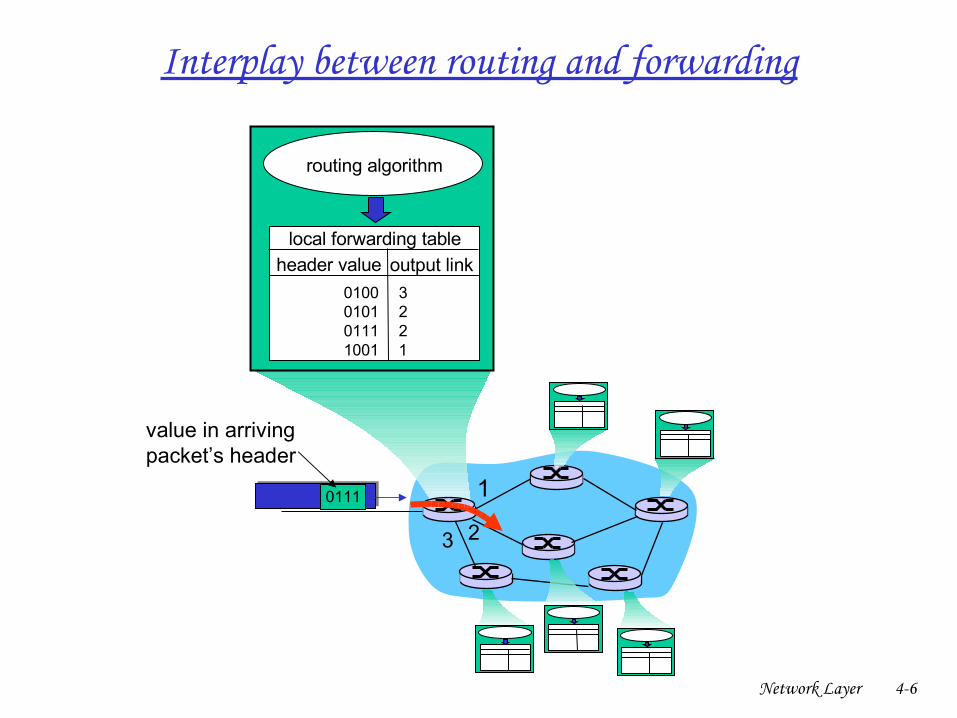
1
23
0111
value in arrivingpacket’s header
routing algorithm
local forwarding tableheader value output link
0100010101111001
3221
Interplay between routing and forwarding
Network Layer 47
Chapter 4: Network Layer
❒ 4. 1 Introduction❒ 4.2 Virtual circuit and
datagram networks❒ 4.3 What’s inside a router❒ 4.4 IP: Internet Protocol
❍ Datagram format❍ IPv4 addressing❍ ICMP❍ IPv6
❒ 4.5 Routing algorithms❍ Link state❍ Distance Vector❍ Hierarchical routing
❒ 4.6 Routing in the Internet❍ RIP❍ OSPF❍ BGP
❒ 4.7 Broadcast and multicast routing
Network Layer 48
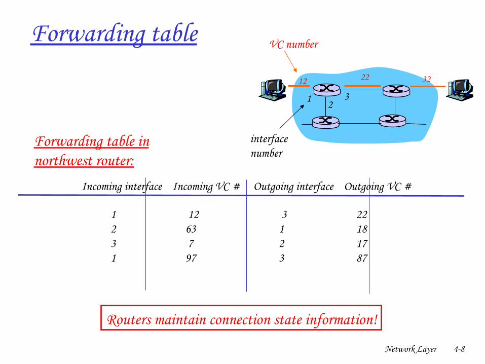
Forwarding table
12 22 32
1 23
VC number
interfacenumber
Incoming interface Incoming VC # Outgoing interface Outgoing VC #
1 12 3 222 63 1 18 3 7 2 171 97 3 87… … … …
Forwarding table innorthwest router:
Routers maintain connection state information!
Network Layer 49
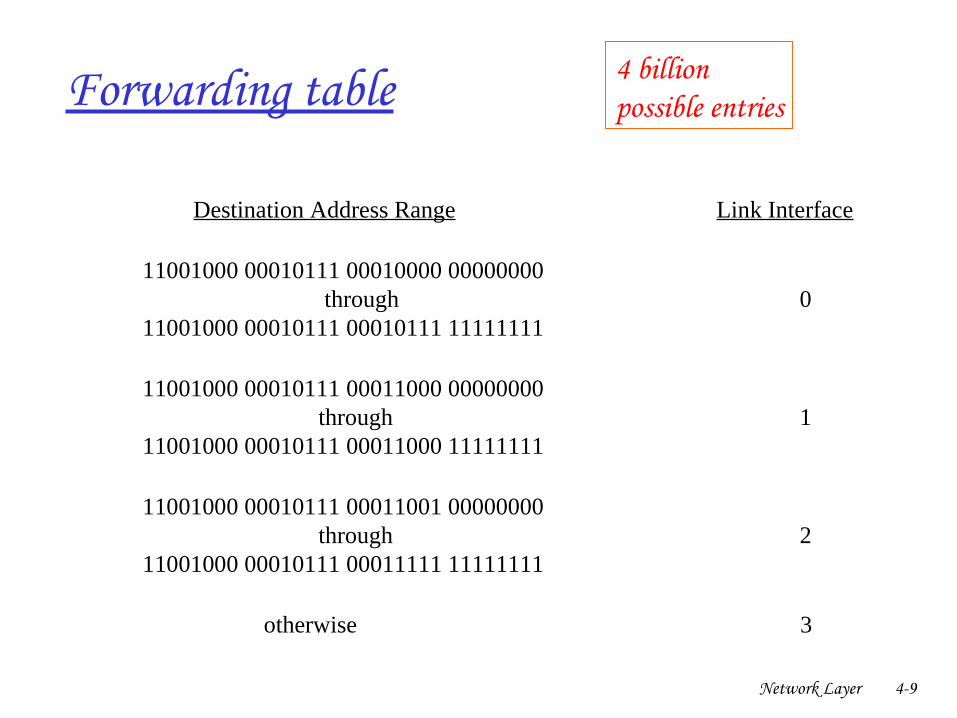
Forwarding table
Destination Address Range Link Interface
11001000 00010111 00010000 00000000 through 0 11001000 00010111 00010111 11111111
11001000 00010111 00011000 00000000 through 1 11001000 00010111 00011000 11111111
11001000 00010111 00011001 00000000 through 2 11001000 00010111 00011111 11111111
otherwise 3
4 billion possible entries
Network Layer 410
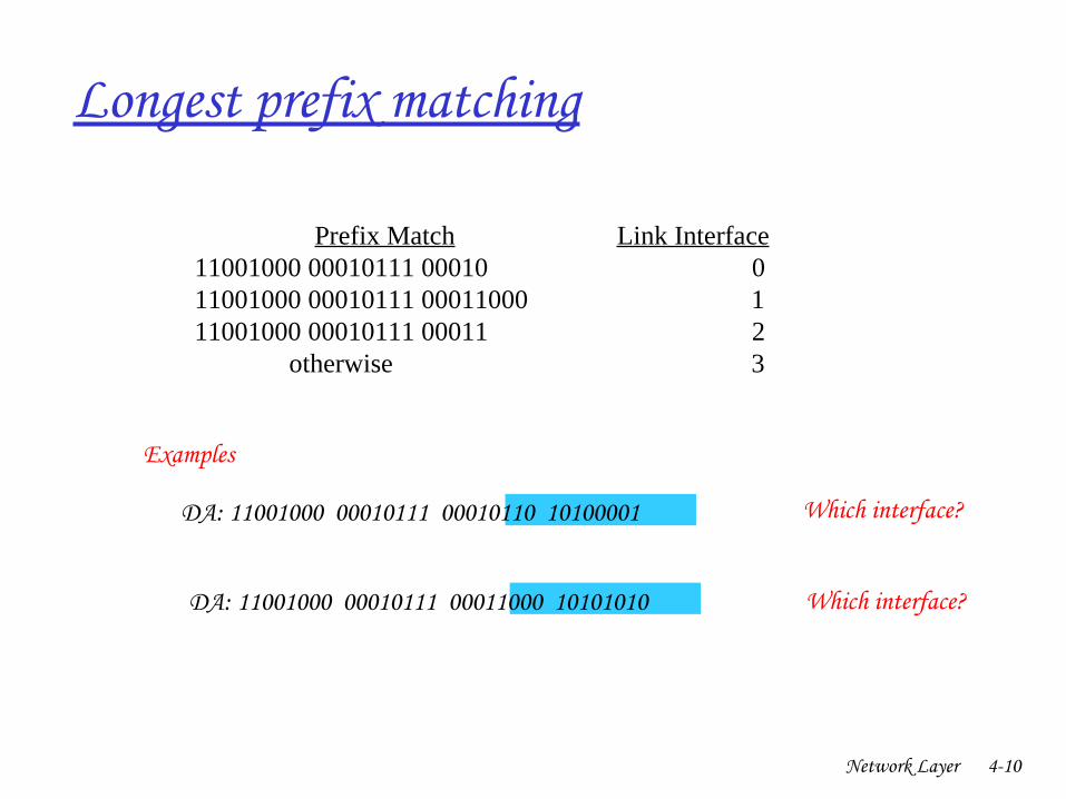
Longest prefix matching
Prefix Match Link Interface 11001000 00010111 00010 0 11001000 00010111 00011000 1 11001000 00010111 00011 2 otherwise 3
DA: 11001000 00010111 00011000 10101010
Examples
DA: 11001000 00010111 00010110 10100001 Which interface?
Which interface?
Network Layer 411
Chapter 4: Network Layer
❒ 4. 1 Introduction❒ 4.2 Virtual circuit and
datagram networks❒ 4.3 What’s inside a router❒ 4.4 IP: Internet Protocol
❍ Datagram format❍ IPv4 addressing❍ ICMP❍ IPv6
❒ 4.5 Routing algorithms❍ Link state❍ Distance Vector❍ Hierarchical routing
❒ 4.6 Routing in the Internet❍ RIP❍ OSPF❍ BGP
❒ 4.7 Broadcast and multicast routing
Network Layer 412
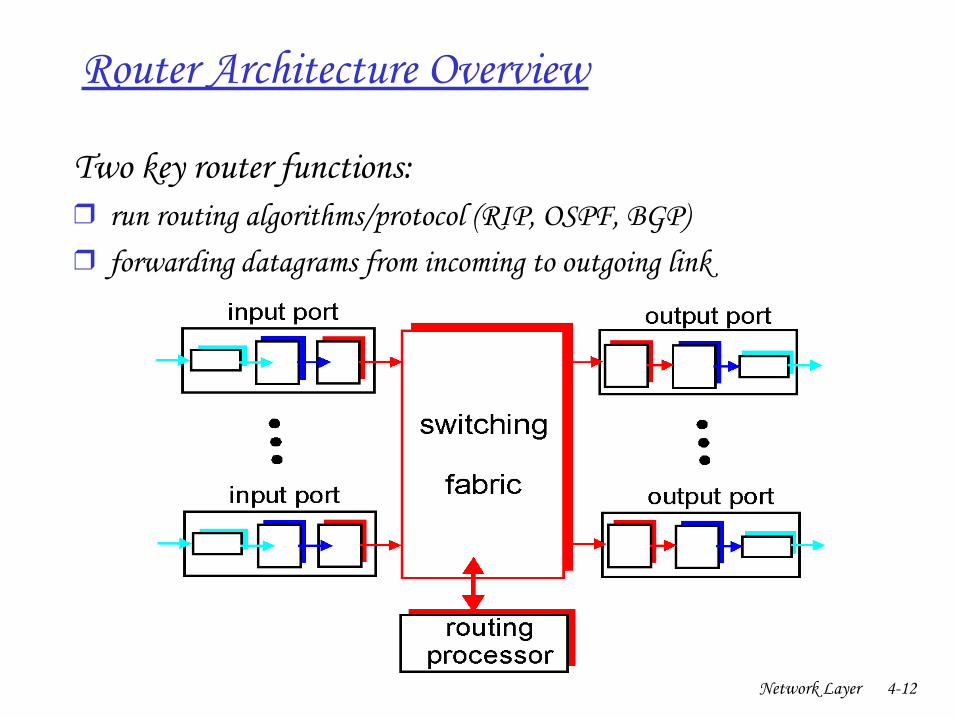
Router Architecture Overview
Two key router functions:
❒ run routing algorithms/protocol (RIP, OSPF, BGP)❒ forwarding datagrams from incoming to outgoing link
Network Layer 413
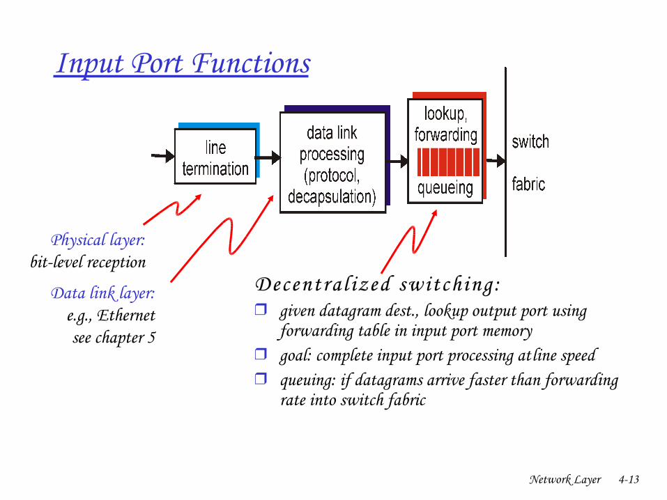
Input Port Functions
Decentra l ized switching : ❒ given datagram dest., lookup output port using
forwarding table in input port memory❒ goal: complete input port processing at ‘line speed’❒ queuing: if datagrams arrive faster than forwarding
rate into switch fabric
Physical layer:bitlevel reception
Data link layer:e.g., Ethernetsee chapter 5
Network Layer 414
Chapter 4: Network Layer
❒ 4. 1 Introduction❒ 4.2 Virtual circuit and
datagram networks❒ 4.3 What’s inside a router❒ 4.4 IP: Internet Protocol
❍ Datagram format❍ IPv4 addressing❍ ICMP❍ IPv6
❒ 4.5 Routing algorithms❍ Link state❍ Distance Vector❍ Hierarchical routing
❒ 4.6 Routing in the Internet❍ RIP❍ OSPF❍ BGP
❒ 4.7 Broadcast and multicast routing
Network Layer 415
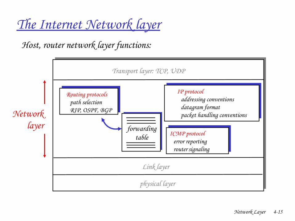
The Internet Network layer
forwardingtable
Host, router network layer functions:
Routing protocols• path selection• RIP, OSPF, BGP
IP protocol• addressing conventions• datagram format• packet handling conventions
ICMP protocol• error reporting• router “signaling”
Transport layer: TCP, UDP
Link layer
physical layer
Networklayer
Network Layer 416
Chapter 4: Network Layer
❒ 4. 1 Introduction❒ 4.2 Virtual circuit and
datagram networks❒ 4.3 What’s inside a router❒ 4.4 IP: Internet Protocol
❍ Datagram format❍ IPv4 addressing❍ ICMP❍ IPv6
❒ 4.5 Routing algorithms❍ Link state❍ Distance Vector❍ Hierarchical routing
❒ 4.6 Routing in the Internet❍ RIP❍ OSPF❍ BGP
❒ 4.7 Broadcast and multicast routing
Network Layer 417
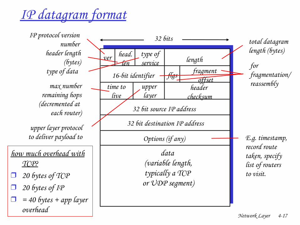
IP datagram format
ver length
32 bits
data (variable length,typically a TCP
or UDP segment)
16bit identifier
header checksum
time tolive
32 bit source IP address
IP protocol versionnumber
header length (bytes)
max numberremaining hops
(decremented at each router)
forfragmentation/reassembly
total datagramlength (bytes)
upper layer protocolto deliver payload to
head.len
type ofservice
“ type” of data flgs fragment offset
upper layer
32 bit destination IP address
Options (if any) E.g. timestamp,record routetaken, specifylist of routers to visit.
how much overhead with TCP?
❒ 20 bytes of TCP❒ 20 bytes of IP❒ = 40 bytes + app layer
overhead
Network Layer 418
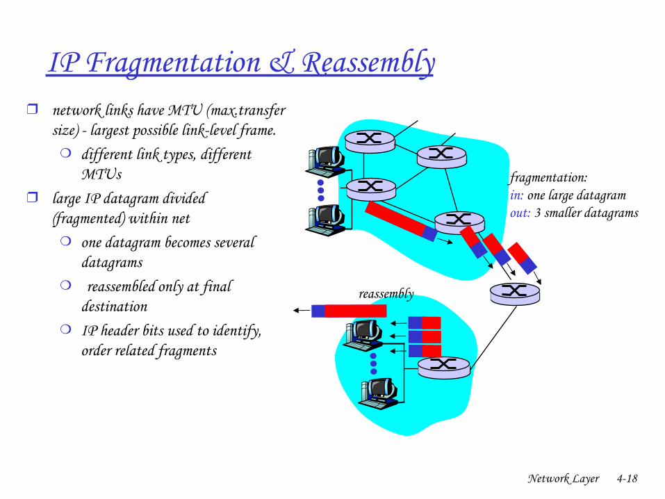
IP Fragmentation & Reassembly❒ network links have MTU (max.transfer
size) largest possible linklevel frame.❍ different link types, different
MTUs ❒ large IP datagram divided
(“fragmented”) within net❍ one datagram becomes several
datagrams❍ “ reassembled” only at final
destination❍ IP header bits used to identify,
order related fragments
fragmentation: in: one large datagramout: 3 smaller datagrams
reassembly
Network Layer 419
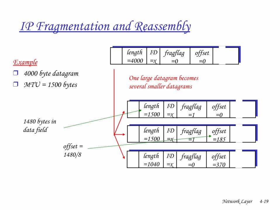
IP Fragmentation and Reassembly
ID=x
offset=0
fragflag=0
length=4000
ID=x
offset=0
fragflag=1
length=1500
ID=x
offset=185
fragflag=1
length=1500
ID=x
offset=370
fragflag=0
length=1040
One large datagram becomesseveral smaller datagrams
Example❒ 4000 byte datagram❒ MTU = 1500 bytes
1480 bytes in data field
offset =1480/8

Network Layer 420
Chapter 4: Network Layer
❒ 4. 1 Introduction❒ 4.2 Virtual circuit and
datagram networks❒ 4.3 What’s inside a router❒ 4.4 IP: Internet Protocol
❍ Datagram format❍ IPv4 addressing❍ ICMP❍ IPv6
❒ 4.5 Routing algorithms❍ Link state❍ Distance Vector❍ Hierarchical routing
❒ 4.6 Routing in the Internet❍ RIP❍ OSPF❍ BGP
❒ 4.7 Broadcast and multicast routing
Network Layer 421
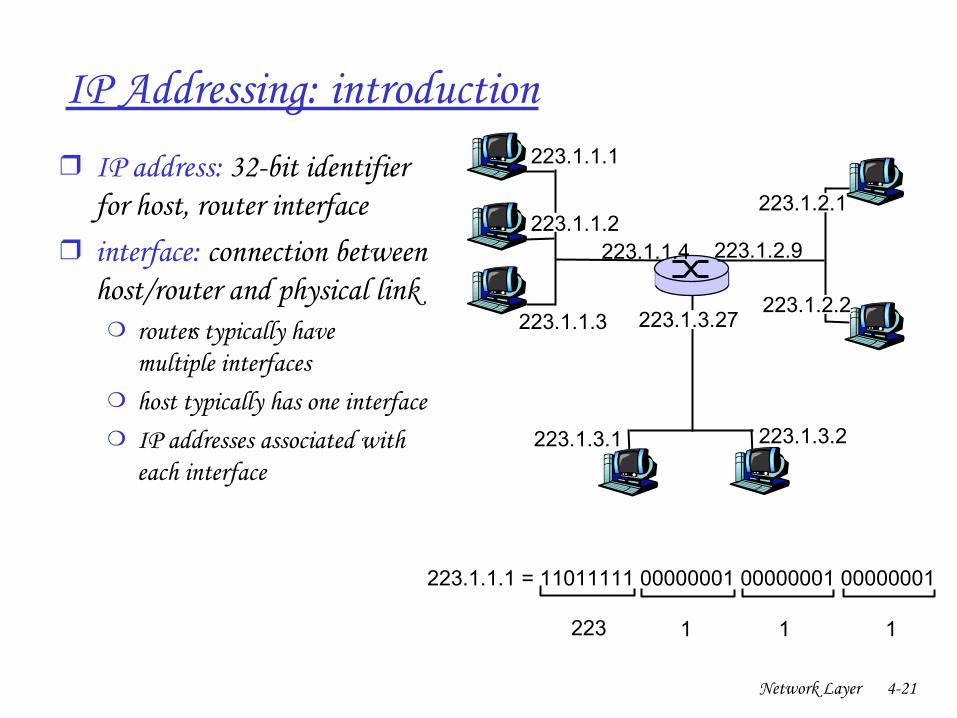
IP Addressing: introduction❒ IP address: 32bit identifier
for host, router interface ❒ interface: connection between
host/router and physical link❍ router’s typically have
multiple interfaces❍ host typically has one interface❍ IP addresses associated with
each interface
223.1.1.1
223.1.1.2
223.1.1.3
223.1.1.4 223.1.2.9
223.1.2.2
223.1.2.1
223.1.3.2223.1.3.1
223.1.3.27
223.1.1.1 = 11011111 00000001 00000001 00000001
223 1 11
Network Layer 422
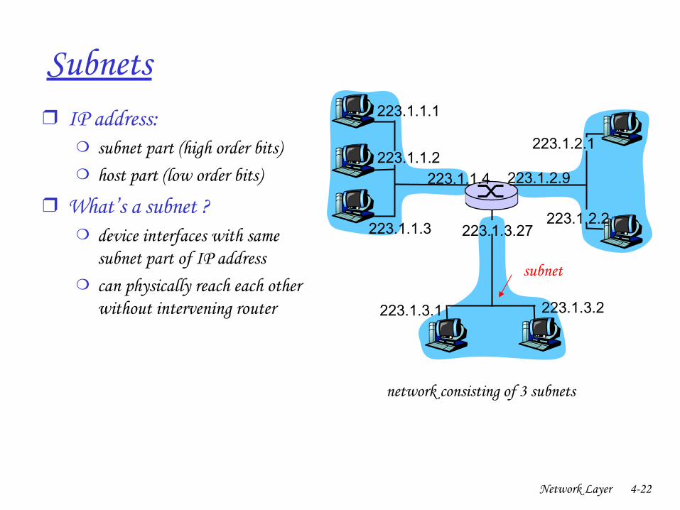
Subnets❒ IP address:
❍ subnet part (high order bits)❍ host part (low order bits)
❒ What’s a subnet ?❍ device interfaces with same
subnet part of IP address❍ can physically reach each other
without intervening router
223.1.1.1
223.1.1.2
223.1.1.3
223.1.1.4 223.1.2.9
223.1.2.2
223.1.2.1
223.1.3.2223.1.3.1
223.1.3.27
network consisting of 3 subnets
subnet
Network Layer 423
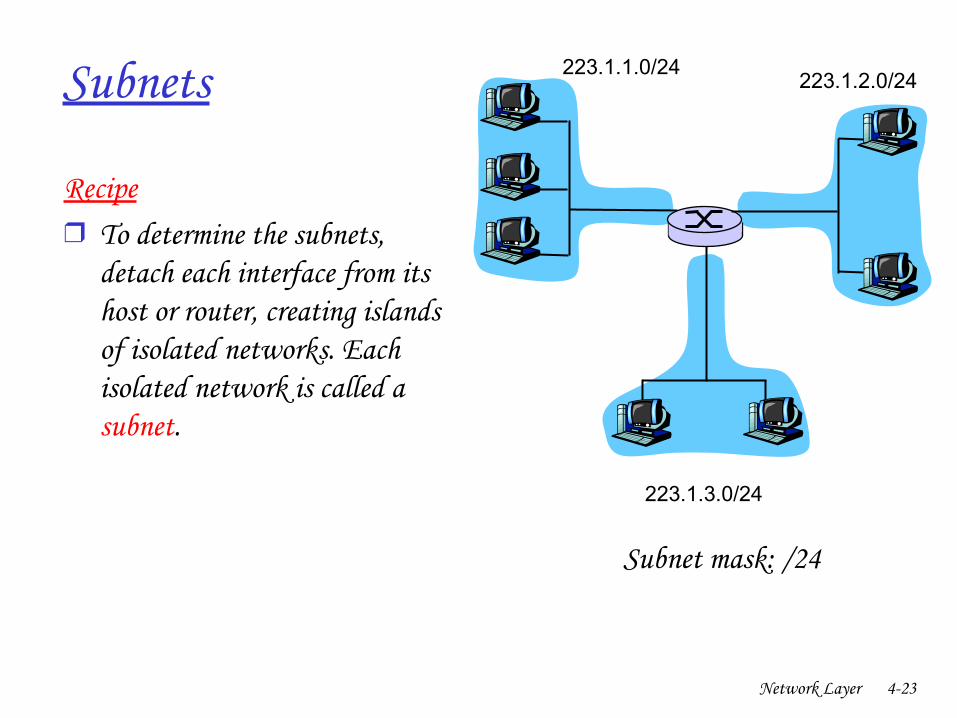
Subnets 223.1.1.0/24223.1.2.0/24
223.1.3.0/24
Recipe❒ To determine the subnets,
detach each interface from its host or router, creating islands of isolated networks. Each isolated network is called a subnet.
Subnet mask: /24
Network Layer 424
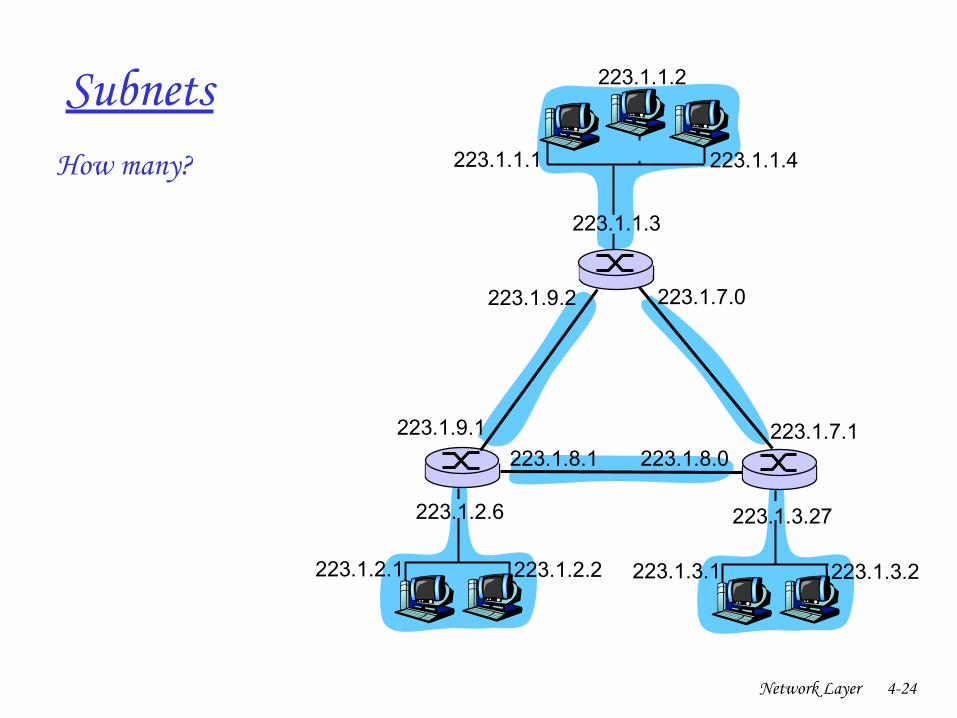
SubnetsHow many? 223.1.1.1
223.1.1.3
223.1.1.4
223.1.2.2223.1.2.1
223.1.2.6
223.1.3.2223.1.3.1
223.1.3.27
223.1.1.2
223.1.7.0
223.1.7.1223.1.8.0223.1.8.1
223.1.9.1
223.1.9.2
Network Layer 425
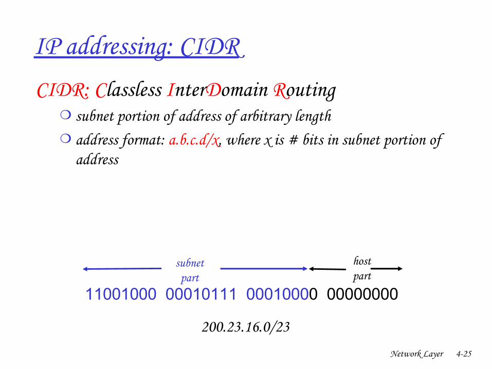
IP addressing: CIDRCIDR: Classless InterDomain Routing
❍ subnet portion of address of arbitrary length❍ address format: a.b.c.d/x, where x is # bits in subnet portion of
address
11001000 00010111 00010000 00000000
subnetpart
hostpart
200.23.16.0/23
Network Layer 426
IP addresses: how to get one?
Q: How does a host get IP address?
❒ hardcoded by system admin in a file❍ Windows: controlpanel>network>configuration>tcp/ip
>properties❍ UNIX: /etc/rc.config
❒ DHCP: Dynamic Host Configuration Protocol: dynamically get address from as server❍ “ plugandplay”
Network Layer 427
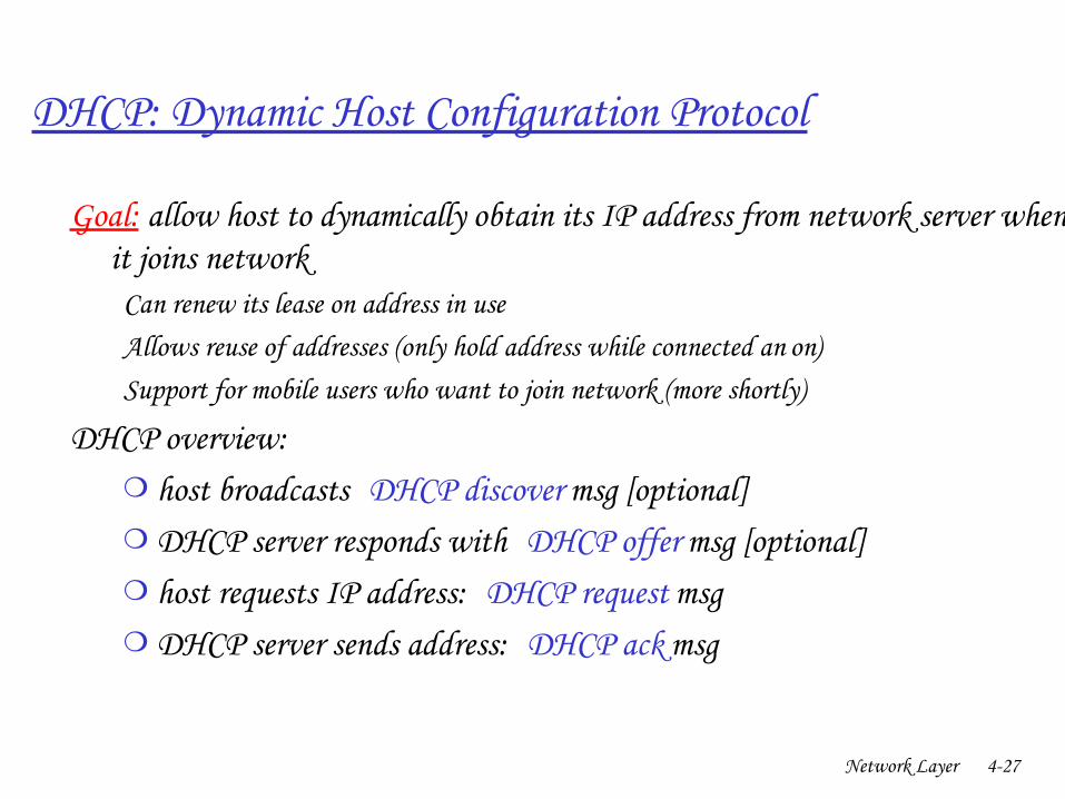
DHCP: Dynamic Host Configuration Protocol
Goal: allow host to dynamically obtain its IP address from network server when it joins network
Can renew its lease on address in useAllows reuse of addresses (only hold address while connected an “on”)Support for mobile users who want to join network (more shortly)
DHCP overview:❍ host broadcasts “ DHCP discover” msg [optional]❍ DHCP server responds with “ DHCP offer” msg [optional]❍ host requests IP address: “ DHCP request” msg❍ DHCP server sends address: “ DHCP ack” msg
Network Layer 428
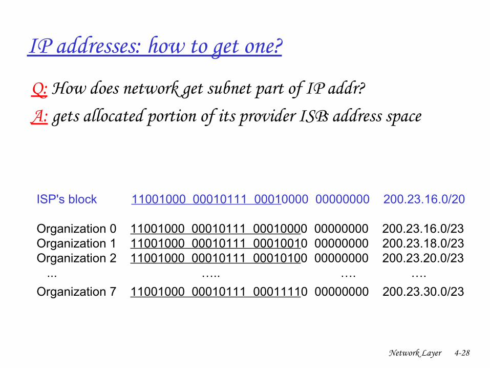
IP addresses: how to get one?
Q: How does network get subnet part of IP addr?A: gets allocated portion of its provider ISP’s address space
ISP's block 11001000 00010111 00010000 00000000 200.23.16.0/20
Organization 0 11001000 00010111 00010000 00000000 200.23.16.0/23 Organization 1 11001000 00010111 00010010 00000000 200.23.18.0/23 Organization 2 11001000 00010111 00010100 00000000 200.23.20.0/23 ... ….. …. ….
Organization 7 11001000 00010111 00011110 00000000 200.23.30.0/23
Network Layer 429
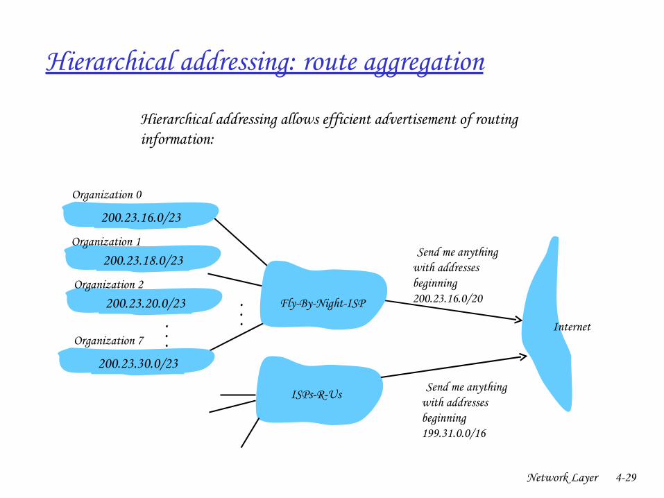
Hierarchical addressing: route aggregation
“ Send me anythingwith addresses beginning 200.23.16.0/20”
200.23.16.0/23
200.23.18.0/23
200.23.30.0/23
FlyByNightISP
Organization 0
Organization 7Internet
Organization 1
ISPsRUs “ Send me anythingwith addresses beginning 199.31.0.0/16”
200.23.20.0/23Organization 2
...
...
Hierarchical addressing allows efficient advertisement of routing information:
Network Layer 430
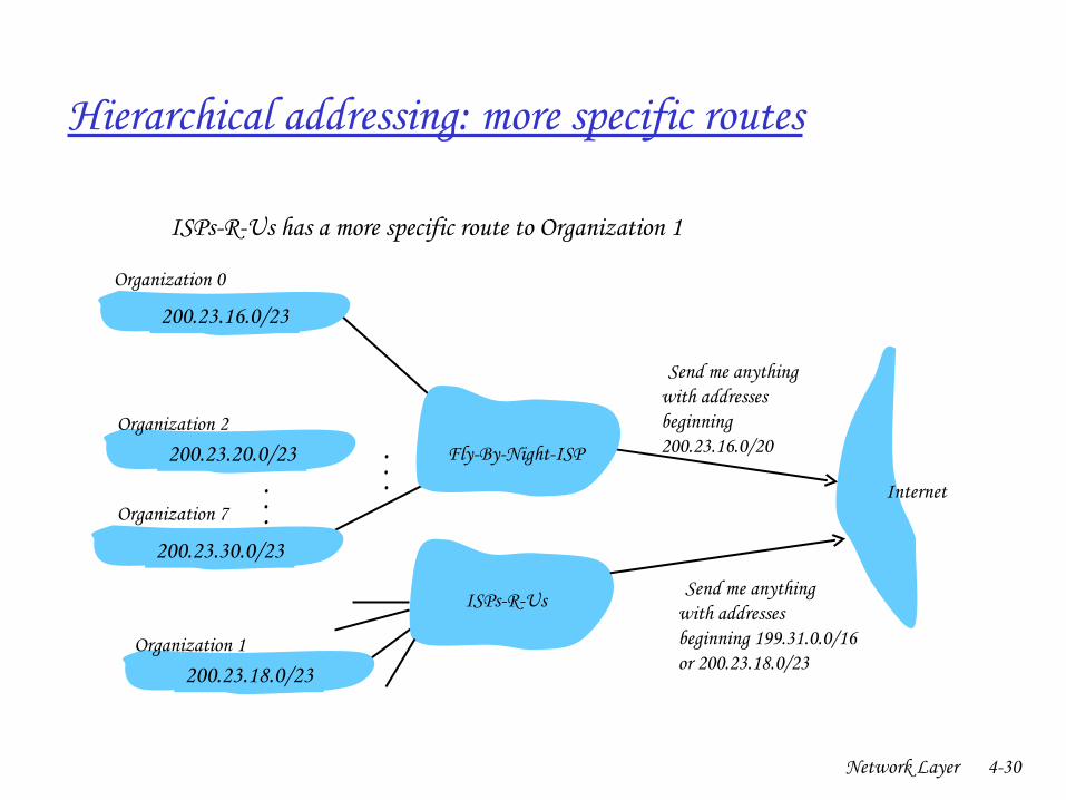
Hierarchical addressing: more specific routes
ISPsRUs has a more specific route to Organization 1
“ Send me anythingwith addresses beginning 200.23.16.0/20”
200.23.16.0/23
200.23.18.0/23
200.23.30.0/23
FlyByNightISP
Organization 0
Organization 7Internet
Organization 1
ISPsRUs “ Send me anythingwith addresses beginning 199.31.0.0/16or 200.23.18.0/23”
200.23.20.0/23Organization 2
...
...

Network Layer 431
NAT: Network Address Translation
10.0.0.1
10.0.0.2
10.0.0.3
10.0.0.4
138.76.29.7
local network(e.g., home network)
10.0.0/24
rest ofInternet
Datagrams with source or destination in this networkhave 10.0.0/24 address for
source, destination (as usual)
All datagrams leaving localnetwork have same single source NAT IP
address: 138.76.29.7,different source port numbers
Network Layer 432
NAT: Network Address Translation
❒ Motivation: local network uses just one IP address as far as outside world is concerned:❍ range of addresses not needed from ISP: just one IP address for all
devices❍ can change addresses of devices in local network without notifying
outside world❍ can change ISP without changing addresses of devices in local network❍ devices inside local net not explicitly addressable, visible by outside
world (a security plus).
Network Layer 433
NAT: Network Address TranslationImplementation: NAT router must:
❍ outgoing datagrams: replace (source IP address, port #) of every outgoing datagram to (NAT IP address, new port #)
. . . remote clients/servers will respond using (NAT IP address, new port #) as destination addr.
❍ remember (in NAT translation table) every (source IP address, port #) to (NAT IP address, new port #) translation pair
❍ incoming datagrams: replace (NAT IP address, new port #) in dest fields of every incoming datagram with corresponding (source IP address, port #) stored in NAT table
Network Layer 434
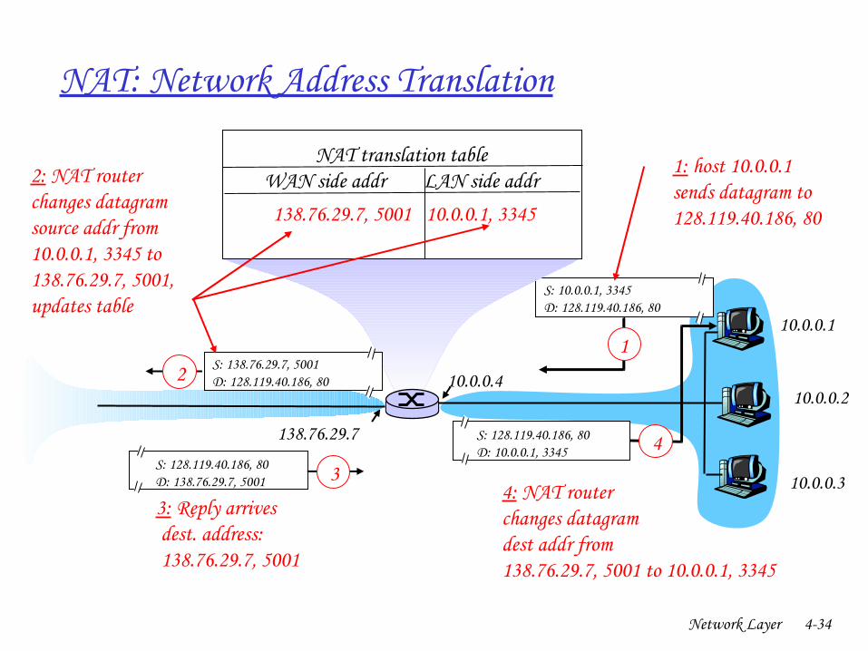
NAT: Network Address Translation
10.0.0.1
10.0.0.2
10.0.0.3
S: 10.0.0.1, 3345D: 128.119.40.186, 80
1
10.0.0.4
138.76.29.7
1: host 10.0.0.1 sends datagram to 128.119.40.186, 80
NAT translation tableWAN side addr LAN side addr138.76.29.7, 5001 10.0.0.1, 3345
… … … …
S: 128.119.40.186, 80 D: 10.0.0.1, 3345 4
S: 138.76.29.7, 5001D: 128.119.40.186, 802
2: NAT routerchanges datagramsource addr from10.0.0.1, 3345 to138.76.29.7, 5001,updates table
S: 128.119.40.186, 80 D: 138.76.29.7, 5001 3
3: Reply arrives dest. address: 138.76.29.7, 5001
4: NAT routerchanges datagramdest addr from138.76.29.7, 5001 to 10.0.0.1, 3345
Network Layer 435
NAT: Network Address Translation
❒ 16bit portnumber field: ❍ 60,000 simultaneous connections with a single LANside
address!
❒ NAT is controversial:❍ routers should only process up to layer 3❍ violates endtoend argument
• NAT possibility must be taken into account by app designers, eg, P2P applications
❍ address shortage should instead be solved by IPv6
Network Layer 436
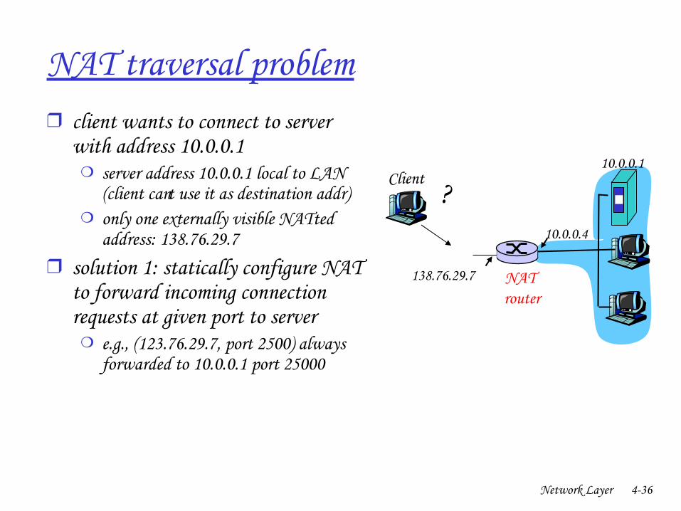
NAT traversal problem❒ client wants to connect to server
with address 10.0.0.1❍ server address 10.0.0.1 local to LAN
(client can’t use it as destination addr)❍ only one externally visible NATted
address: 138.76.29.7❒ solution 1: statically configure NAT
to forward incoming connection requests at given port to server
❍ e.g., (123.76.29.7, port 2500) always forwarded to 10.0.0.1 port 25000
10.0.0.1
10.0.0.4
NAT router
138.76.29.7
Client?
Network Layer 437
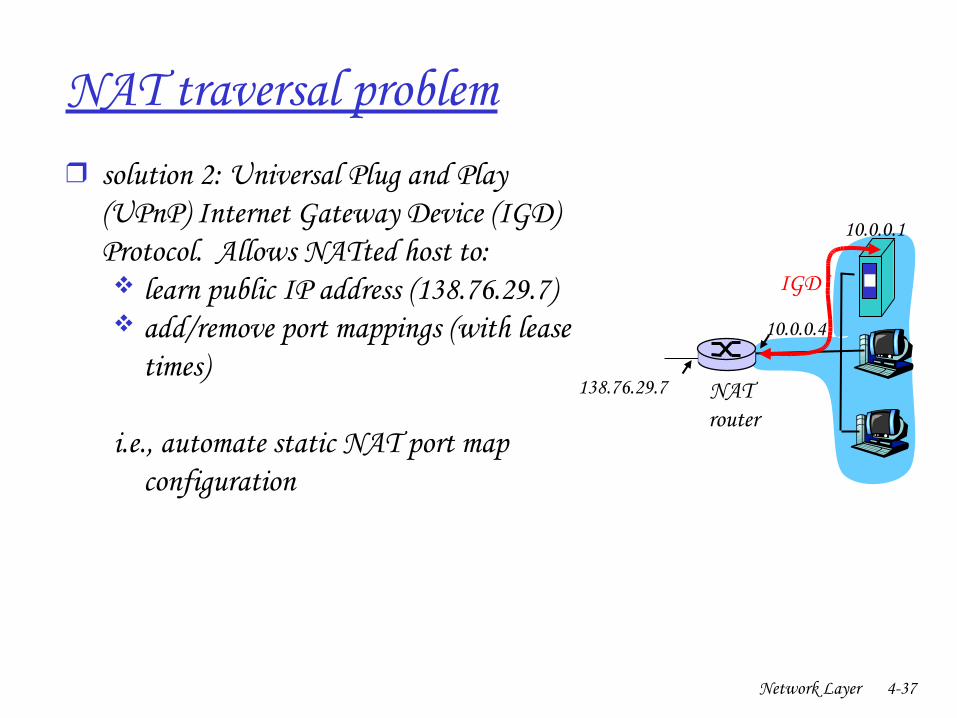
NAT traversal problem❒ solution 2: Universal Plug and Play
(UPnP) Internet Gateway Device (IGD) Protocol. Allows NATted host to: learn public IP address (138.76.29.7) add/remove port mappings (with lease
times)
i.e., automate static NAT port map configuration
10.0.0.1
10.0.0.4
NAT router
138.76.29.7
IGD
Network Layer 438
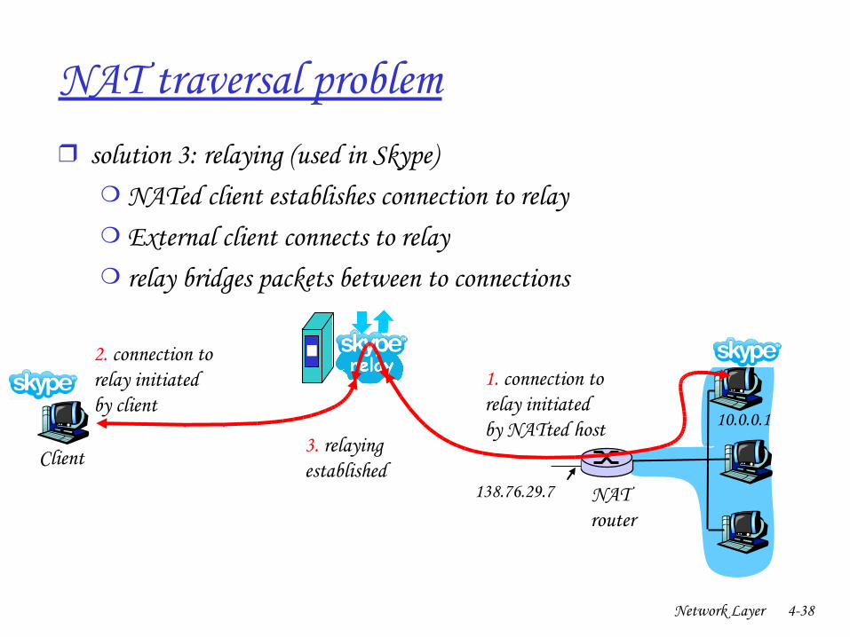
NAT traversal problem❒ solution 3: relaying (used in Skype)
❍ NATed client establishes connection to relay❍ External client connects to relay❍ relay bridges packets between to connections
138.76.29.7
Client
10.0.0.1
NAT router
1. connection torelay initiatedby NATted host
2. connection torelay initiatedby client
3. relaying established
Network Layer 439
Chapter 4: Network Layer
❒ 4. 1 Introduction❒ 4.2 Virtual circuit and
datagram networks❒ 4.3 What’s inside a router❒ 4.4 IP: Internet Protocol
❍ Datagram format❍ IPv4 addressing❍ ICMP❍ IPv6
❒ 4.5 Routing algorithms❍ Link state❍ Distance Vector❍ Hierarchical routing
❒ 4.6 Routing in the Internet❍ RIP❍ OSPF❍ BGP
❒ 4.7 Broadcast and multicast routing
Network Layer 440
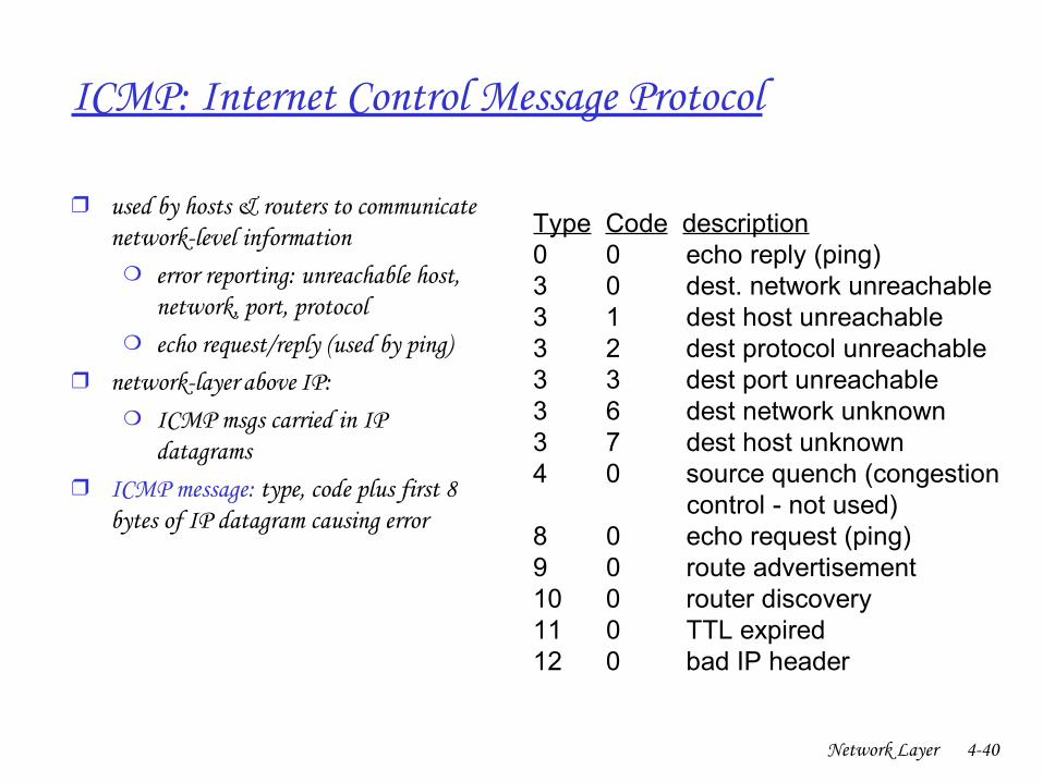
ICMP: Internet Control Message Protocol
❒ used by hosts & routers to communicate networklevel information
❍ error reporting: unreachable host, network, port, protocol
❍ echo request/reply (used by ping)❒ networklayer “above” IP:
❍ ICMP msgs carried in IP datagrams
❒ ICMP message: type, code plus first 8 bytes of IP datagram causing error
Type Code description0 0 echo reply (ping)3 0 dest. network unreachable3 1 dest host unreachable3 2 dest protocol unreachable3 3 dest port unreachable3 6 dest network unknown3 7 dest host unknown4 0 source quench (congestion control - not used)8 0 echo request (ping)9 0 route advertisement10 0 router discovery11 0 TTL expired12 0 bad IP header
Network Layer 441
Traceroute and ICMP
❒ Source sends series of UDP segments to dest
❍ First has TTL =1❍ Second has TTL=2, etc.❍ Unlikely port number
❒ When nth datagram arrives to nth router:
❍ Router discards datagram❍ And sends to source an ICMP
message (type 11, code 0)❍ Message includes name of router&
IP address
❒ When ICMP message arrives, source calculates RTT
❒ Traceroute does this 3 timesStopping criterion❒ UDP segment eventually arrives at
destination host❒ Destination returns ICMP “host
unreachable” packet (type 3, code 3)❒ When source gets this ICMP, stops.
Network Layer 442
Chapter 4: Network Layer
❒ 4. 1 Introduction❒ 4.2 Virtual circuit and
datagram networks❒ 4.3 What’s inside a router❒ 4.4 IP: Internet Protocol
❍ Datagram format❍ IPv4 addressing❍ ICMP❍ IPv6
❒ 4.5 Routing algorithms❍ Link state❍ Distance Vector❍ Hierarchical routing
❒ 4.6 Routing in the Internet❍ RIP❍ OSPF❍ BGP
❒ 4.7 Broadcast and multicast routing
Network Layer 443
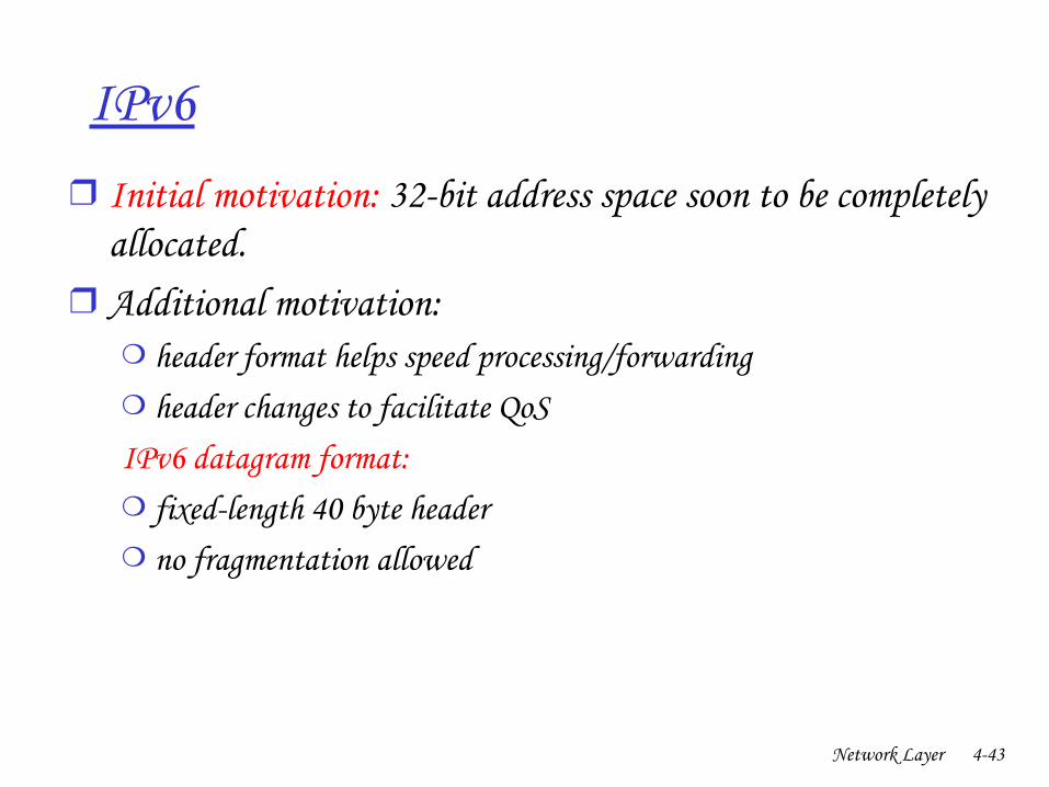
IPv6❒ Initial motivation: 32bit address space soon to be completely
allocated. ❒ Additional motivation:
❍ header format helps speed processing/forwarding❍ header changes to facilitate QoS IPv6 datagram format: ❍ fixedlength 40 byte header❍ no fragmentation allowed

Network Layer 444
Chapter 4: Network Layer
❒ 4. 1 Introduction❒ 4.2 Virtual circuit and
datagram networks❒ 4.3 What’s inside a router❒ 4.4 IP: Internet Protocol
❍ Datagram format❍ IPv4 addressing❍ ICMP❍ IPv6
❒ 4.5 Routing algorithms❍ Link state❍ Distance Vector❍ Hierarchical routing
❒ 4.6 Routing in the Internet❍ RIP❍ OSPF❍ BGP
❒ 4.7 Broadcast and multicast routing
Network Layer 445
1
23
0111
value in arrivingpacket’s header
routing algorithm
local forwarding tableheader value output link
0100010101111001
3221
Interplay between routing, forwarding
Network Layer 446
u
yx
wv
z2
21
3
1
1
2
53
5
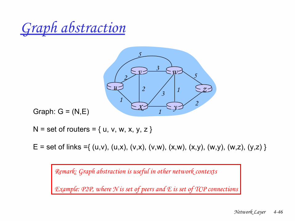
Graph: G = (N,E)
N = set of routers = { u, v, w, x, y, z }
E = set of links ={ (u,v), (u,x), (v,x), (v,w), (x,w), (x,y), (w,y), (w,z), (y,z) }
Graph abstraction
Remark: Graph abstraction is useful in other network contexts
Example: P2P, where N is set of peers and E is set of TCP connections
Network Layer 447
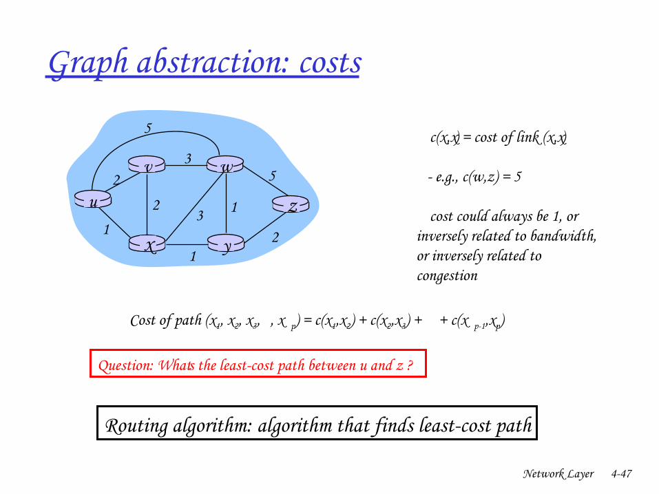
Graph abstraction: costs
u
yx
wv
z2
21
3
1
1
2
53
5 • c(x,x’) = cost of link (x,x’)
e.g., c(w,z) = 5
• cost could always be 1, or inversely related to bandwidth,or inversely related to congestion
Cost of path (x1, x2, x3,… , x p) = c(x1,x2) + c(x2,x3) + … + c(x p1,xp)
Question: What’s the leastcost path between u and z ?
Routing algorithm: algorithm that finds leastcost path
Network Layer 448
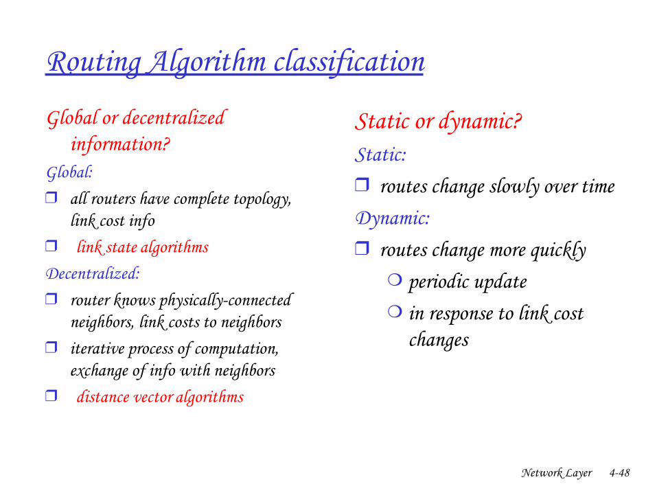
Routing Algorithm classification
Global or decentralized information?
Global:❒ all routers have complete topology,
link cost info❒ “ link state” algorithmsDecentralized: ❒ router knows physicallyconnected
neighbors, link costs to neighbors❒ iterative process of computation,
exchange of info with neighbors❒ “ distance vector” algorithms
Static or dynamic?Static: ❒ routes change slowly over timeDynamic: ❒ routes change more quickly
❍ periodic update❍ in response to link cost
changes

Network Layer 449
Chapter 4: Network Layer
❒ 4. 1 Introduction❒ 4.2 Virtual circuit and
datagram networks❒ 4.3 What’s inside a router❒ 4.4 IP: Internet Protocol
❍ Datagram format❍ IPv4 addressing❍ ICMP❍ IPv6
❒ 4.5 Routing algorithms❍ Link state❍ Distance Vector❍ Hierarchical routing
❒ 4.6 Routing in the Internet❍ RIP❍ OSPF❍ BGP
❒ 4.7 Broadcast and multicast routing
Network Layer 450
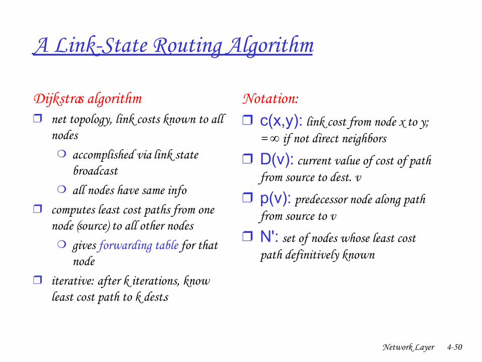
A LinkState Routing Algorithm
Dijkstra’s algorithm❒ net topology, link costs known to all
nodes❍ accomplished via “link state
broadcast” ❍ all nodes have same info
❒ computes least cost paths from one node (‘source”) to all other nodes
❍ gives forwarding table for that node
❒ iterative: after k iterations, know least cost path to k dest.’s
Notation:❒ c(x,y): link cost from node x to y;
= if not direct neighbors∞
❒ D(v): current value of cost of path from source to dest. v
❒ p(v): predecessor node along path from source to v
❒ N': set of nodes whose least cost path definitively known
Network Layer 451
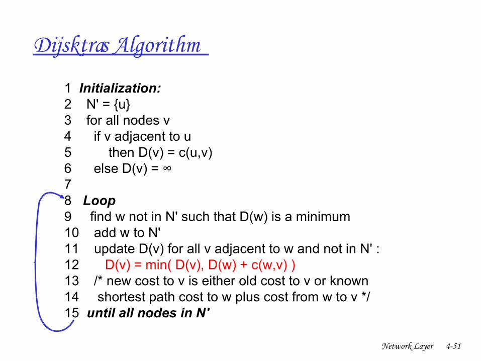
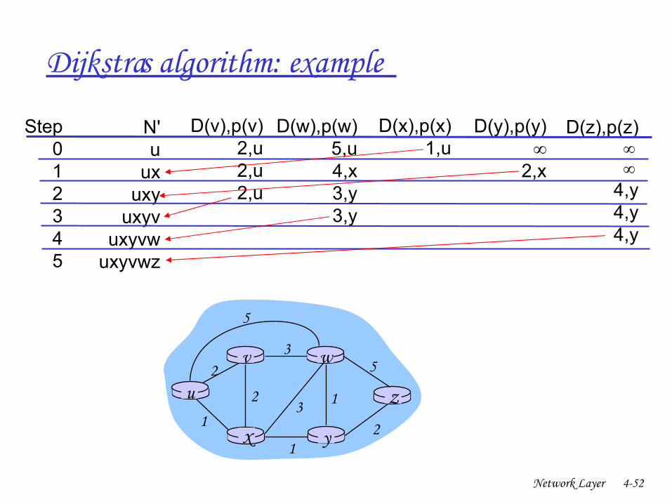
Dijsktra’s Algorithm
1 Initialization: 2 N' = {u} 3 for all nodes v 4 if v adjacent to u 5 then D(v) = c(u,v) 6 else D(v) = ∞ 7 8 Loop 9 find w not in N' such that D(w) is a minimum 10 add w to N' 11 update D(v) for all v adjacent to w and not in N' : 12 D(v) = min( D(v), D(w) + c(w,v) ) 13 /* new cost to v is either old cost to v or known 14 shortest path cost to w plus cost from w to v */ 15 until all nodes in N'
Network Layer 452
Dijkstra’s algorithm: example
Step012345
N'u
uxuxy
uxyvuxyvw
uxyvwz
D(v),p(v)2,u2,u2,u
D(w),p(w)5,u4,x3,y3,y
D(x),p(x)1,u
D(y),p(y)∞
2,x
D(z),p(z) ∞ ∞
4,y4,y4,y
u
yx
wv
z2
21
3
1
1
2
53
5
Network Layer 453
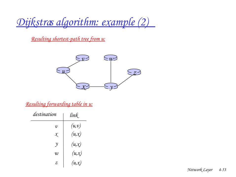
Dijkstra’s algorithm: example (2)
u
yx
wv
z
Resulting shortestpath tree from u:
vx
y
w
z
(u,v)(u,x)
(u,x)(u,x)
(u,x)
destination link
Resulting forwarding table in u:
Network Layer 454
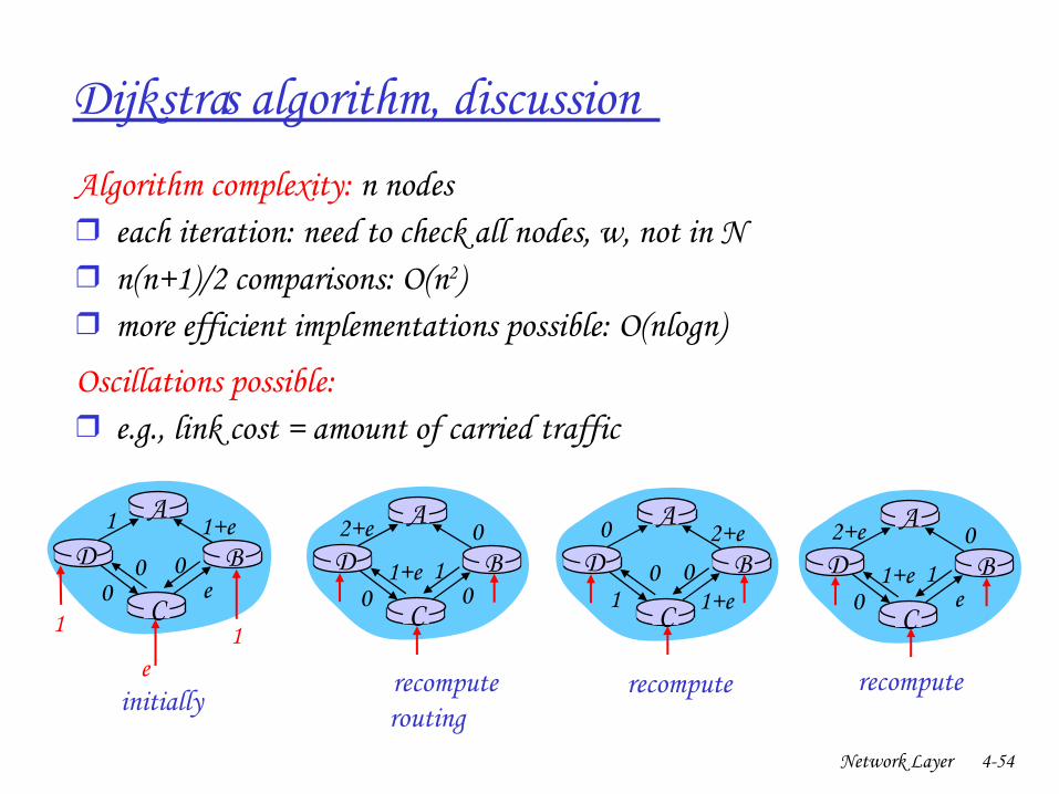
Dijkstra’s algorithm, discussion
Algorithm complexity: n nodes❒ each iteration: need to check all nodes, w, not in N❒ n(n+1)/2 comparisons: O(n2)❒ more efficient implementations possible: O(nlogn)
Oscillations possible:❒ e.g., link cost = amount of carried traffic
A
D
C
B1 1+e
e0
e
1 1
0 0
A
D
C
B2+e 0
001+e 1
A
D
C
B0 2+e
1+e10 0
A
D
C
B2+e 0
e01+e 1
initially… recompute
routing… recompute … recompute

Network Layer 455
Chapter 4: Network Layer
❒ 4. 1 Introduction❒ 4.2 Virtual circuit and
datagram networks❒ 4.3 What’s inside a router❒ 4.4 IP: Internet Protocol
❍ Datagram format❍ IPv4 addressing❍ ICMP❍ IPv6
❒ 4.5 Routing algorithms❍ Link state❍ Distance Vector❍ Hierarchical routing
❒ 4.6 Routing in the Internet❍ RIP❍ OSPF❍ BGP
❒ 4.7 Broadcast and multicast routing
Network Layer 456
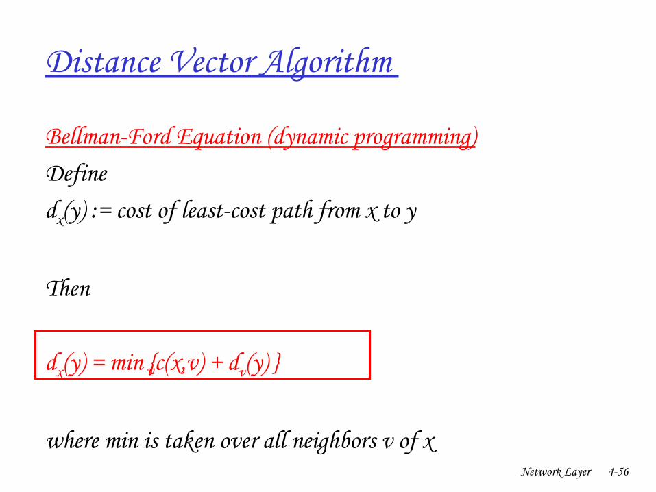
Distance Vector Algorithm
BellmanFord Equation (dynamic programming)Definedx(y) := cost of leastcost path from x to y
Then
dx(y) = min {c(x,v) + dv(y) }
where min is taken over all neighbors v of x
v
Network Layer 457
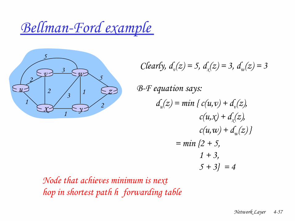
BellmanFord example
u
yx
wv
z2
21
3
1
1
2
53
5Clearly, dv(z) = 5, dx(z) = 3, dw(z) = 3
du(z) = min { c(u,v) + dv(z), c(u,x) + dx(z), c(u,w) + dw(z) } = min {2 + 5, 1 + 3, 5 + 3} = 4
Node that achieves minimum is nexthop in shortest path h forwarding table
BF equation says:
Network Layer 458
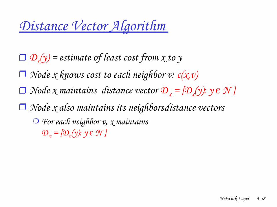
Distance Vector Algorithm
❒ Dx(y) = estimate of least cost from x to y❒ Node x knows cost to each neighbor v: c(x,v)❒ Node x maintains distance vector D x = [Dx(y): y є N ]❒ Node x also maintains its neighbors’ distance vectors
❍ For each neighbor v, x maintains D v = [Dv(y): y є N ]
Network Layer 459
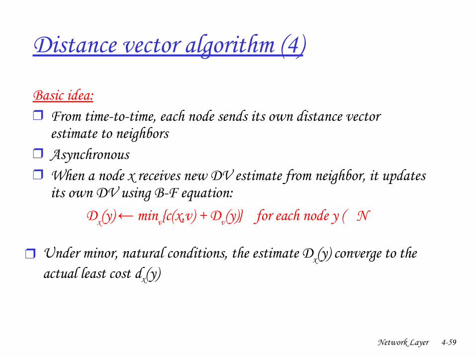
Distance vector algorithm (4)
Basic idea: ❒ From timetotime, each node sends its own distance vector
estimate to neighbors❒ Asynchronous❒ When a node x receives new DV estimate from neighbor, it updates
its own DV using BF equation:Dx(y) min← v{c(x,v) + Dv(y)} for each node y ( N
❒ Under minor, natural conditions, the estimate Dx(y) converge to the actual least cost dx(y)
Network Layer 460
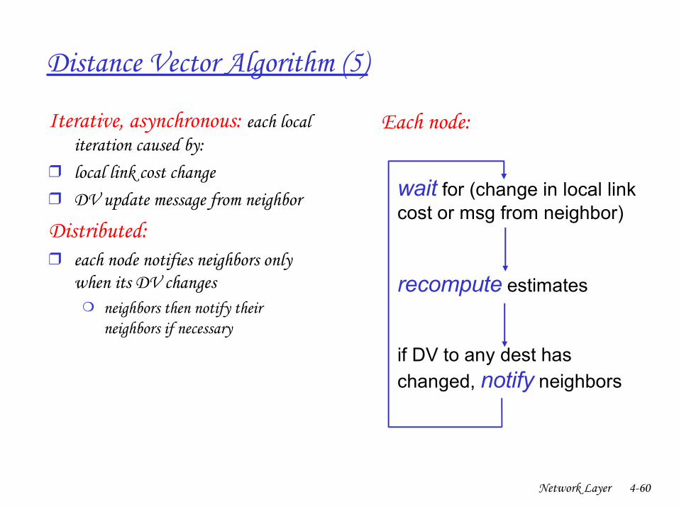
Distance Vector Algorithm (5)
Iterative, asynchronous: each local iteration caused by:
❒ local link cost change ❒ DV update message from neighbor
Distributed:❒ each node notifies neighbors only
when its DV changes❍ neighbors then notify their
neighbors if necessary
wait for (change in local link cost or msg from neighbor)
recompute estimates
if DV to any dest has
changed, notify neighbors
Each node:
Network Layer 461
x y z
xyz
0 2 7
∞ ∞ ∞∞ ∞ ∞
from
cost to
from
from
x y z
xyz
0
from
cost to
x y z
xyz
∞ ∞
∞ ∞ ∞
cost to
x y z
xyz
∞ ∞ ∞7 1 0
cost to
∞2 0 1
∞ ∞ ∞
2 0 17 1 0
time
x z12
7
y
node x tab le
node y table
node z table
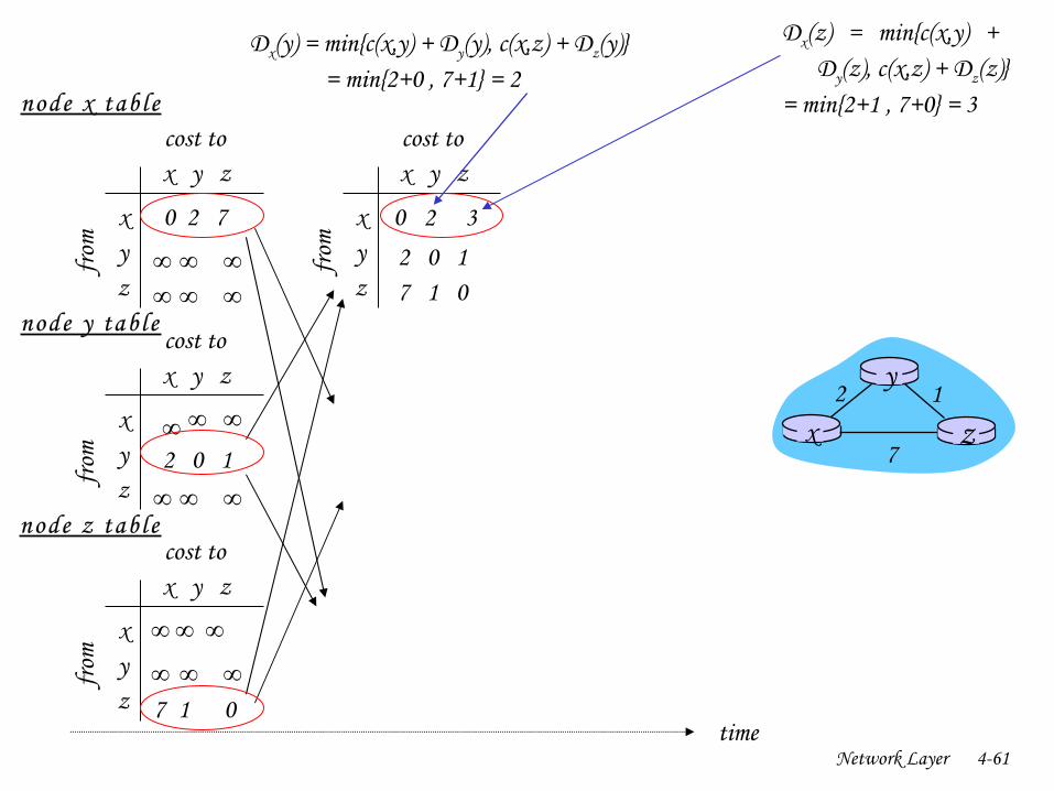
Dx(y) = min{c(x,y) + Dy(y), c(x,z) + Dz(y)} = min{2+0 , 7+1} = 2
Dx(z) = min{c(x,y) + Dy(z), c(x,z) + Dz(z)} = min{2+1 , 7+0} = 3
32
Network Layer 462
x y z
xyz
0 2 7
∞ ∞ ∞∞ ∞ ∞
from
cost to
from
from
x y z
xyz
0 2 3
from
cost tox y z
xyz
0 2 3
from
cost to
x y z
xyz
∞ ∞
∞ ∞ ∞
cost tox y z
xyz
0 2 7
from
cost to
x y z
xyz
0 2 3
from
cost to
x y z
xyz
0 2 3
from
cost tox y z
xyz
0 2 7
from
cost to
x y z
xyz
∞ ∞ ∞7 1 0
cost to
∞2 0 1
∞ ∞ ∞
2 0 17 1 0
2 0 17 1 0
2 0 13 1 0
2 0 13 1 0
2 0 1
3 1 0
2 0 1
3 1 0
time
x z12
7
y
node x tab le
node y table
node z table
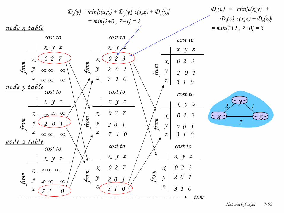
Dx(y) = min{c(x,y) + Dy(y), c(x,z) + Dz(y)} = min{2+0 , 7+1} = 2
Dx(z) = min{c(x,y) + Dy(z), c(x,z) + Dz(z)} = min{2+1 , 7+0} = 3
Network Layer 463
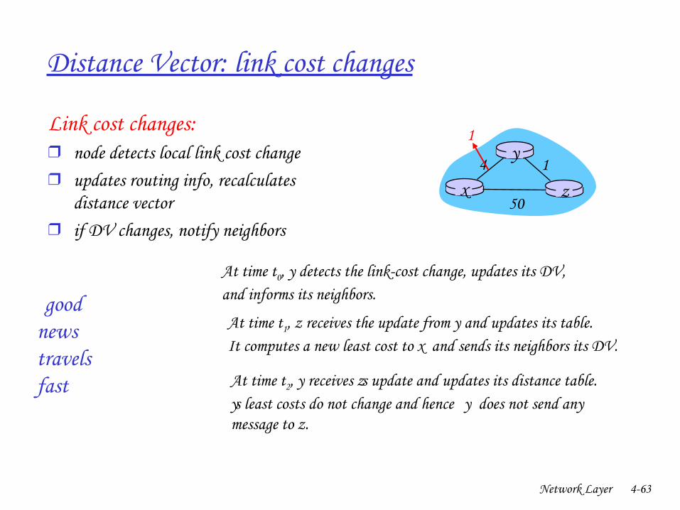
Distance Vector: link cost changes
Link cost changes:❒ node detects local link cost change ❒ updates routing info, recalculates
distance vector❒ if DV changes, notify neighbors
“ goodnews travelsfast”
x z14
50
y1
At time t0, y detects the linkcost change, updates its DV, and informs its neighbors.
At time t1, z receives the update from y and updates its table. It computes a new least cost to x and sends its neighbors its DV.
At time t2, y receives z ’s update and updates its distance table. y ’s least costs do not change and hence y does not send any message to z.
Network Layer 464
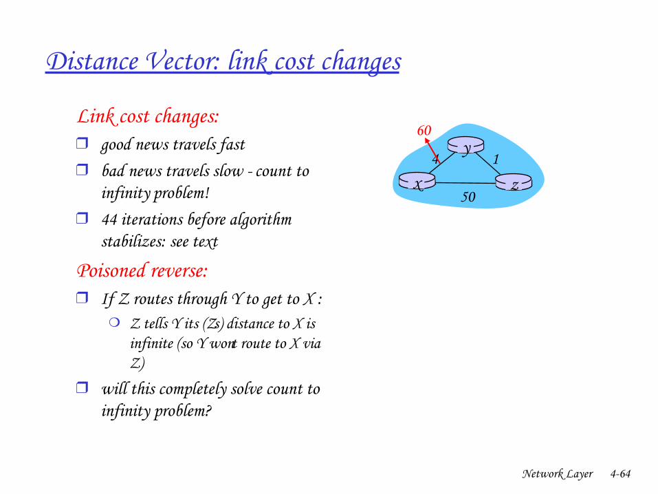
Distance Vector: link cost changes
Link cost changes:❒ good news travels fast ❒ bad news travels slow “count to
infinity” problem!❒ 44 iterations before algorithm
stabilizes: see text
Poisoned reverse: ❒ If Z routes through Y to get to X :
❍ Z tells Y its (Z’s) distance to X is infinite (so Y won’t route to X via Z)
❒ will this completely solve count to infinity problem?
x z14
50
y60
Network Layer 465
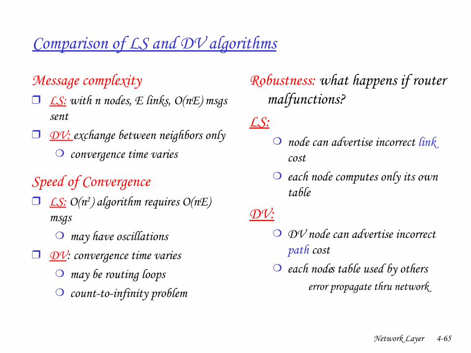
Comparison of LS and DV algorithms
Message complexity❒ LS: with n nodes, E links, O(nE) msgs
sent ❒ DV: exchange between neighbors only
❍ convergence time varies
Speed of Convergence❒ LS: O(n2) algorithm requires O(nE)
msgs❍ may have oscillations
❒ DV: convergence time varies❍ may be routing loops❍ counttoinfinity problem
Robustness: what happens if router malfunctions?
LS: ❍ node can advertise incorrect link
cost❍ each node computes only its own
table
DV:❍ DV node can advertise incorrect
path cost❍ each node’s table used by others
• error propagate thru network
Network Layer 466
Chapter 4: Network Layer
❒ 4. 1 Introduction❒ 4.2 Virtual circuit and
datagram networks❒ 4.3 What’s inside a router❒ 4.4 IP: Internet Protocol
❍ Datagram format❍ IPv4 addressing❍ ICMP❍ IPv6
❒ 4.5 Routing algorithms❍ Link state❍ Distance Vector❍ Hierarchical routing
❒ 4.6 Routing in the Internet❍ RIP❍ OSPF❍ BGP
❒ 4.7 Broadcast and multicast routing
Network Layer 467
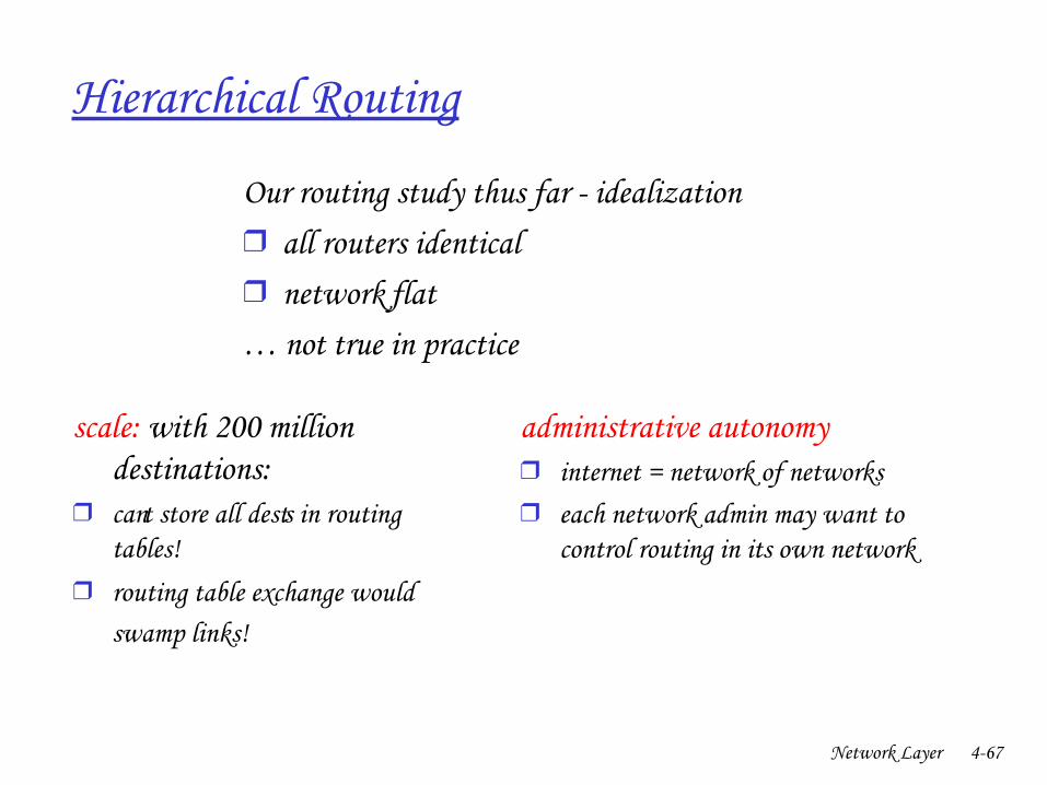
Hierarchical Routing
scale: with 200 million destinations:
❒ can’t store all dest’s in routing tables!
❒ routing table exchange would swamp links!
administrative autonomy❒ internet = network of networks❒ each network admin may want to
control routing in its own network
Our routing study thus far idealization ❒ all routers identical❒ network “flat”… not true in practice
Network Layer 468
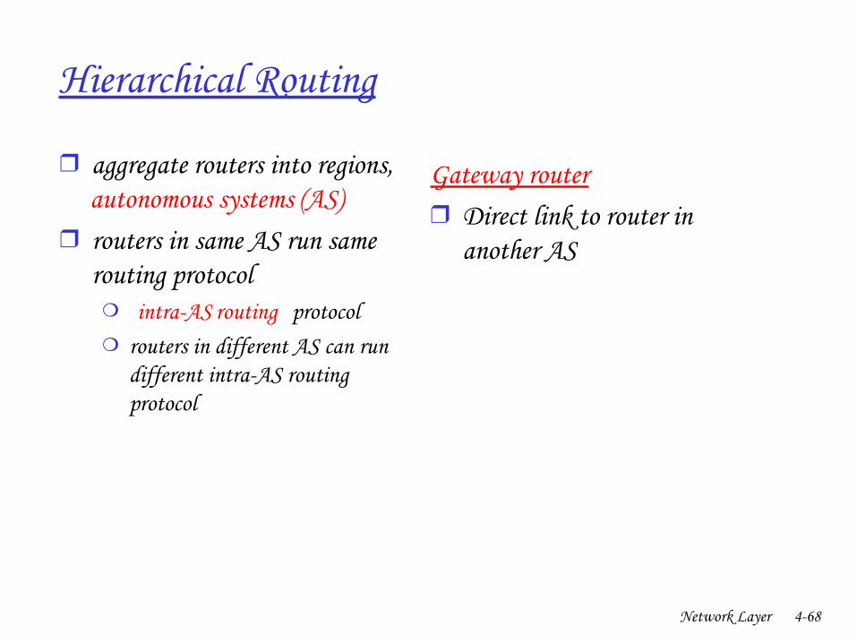
Hierarchical Routing
❒ aggregate routers into regions, “autonomous systems” (AS)
❒ routers in same AS run same routing protocol
❍ “ intraAS” routing protocol❍ routers in different AS can run
different intraAS routing protocol
Gateway router❒ Direct link to router in
another AS
Network Layer 469
3b
1d
3a
1c2aAS3
AS1
AS21a
2c2b
1b
Intra-ASRouting algorithm
Inter-ASRouting algorithm
Forwardingtable
3c
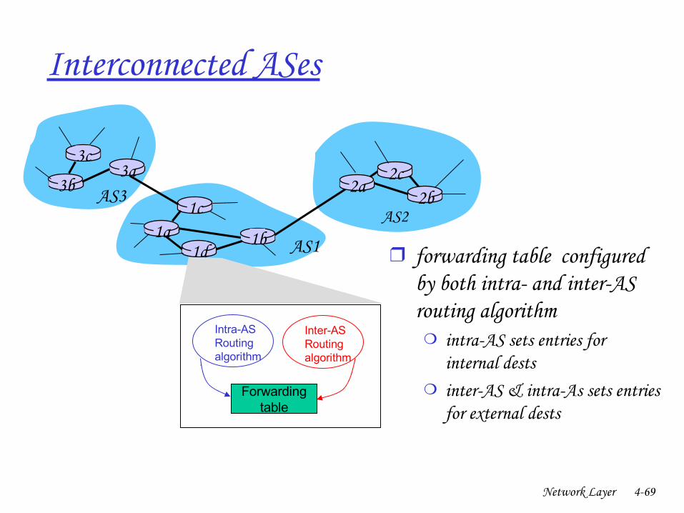
Interconnected ASes
❒ forwarding table configured by both intra and interAS routing algorithm
❍ intraAS sets entries for internal dests
❍ interAS & intraAs sets entries for external dests
Network Layer 470
3b
1d
3a
1c2aAS3
AS1
AS21a
2c2b
1b
3c
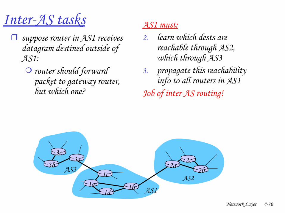
InterAS tasks❒ suppose router in AS1 receives
datagram destined outside of AS1:❍ router should forward
packet to gateway router, but which one?
AS1 must:2. learn which dests are
reachable through AS2, which through AS3
3. propagate this reachability info to all routers in AS1
Job of interAS routing!
Network Layer 471
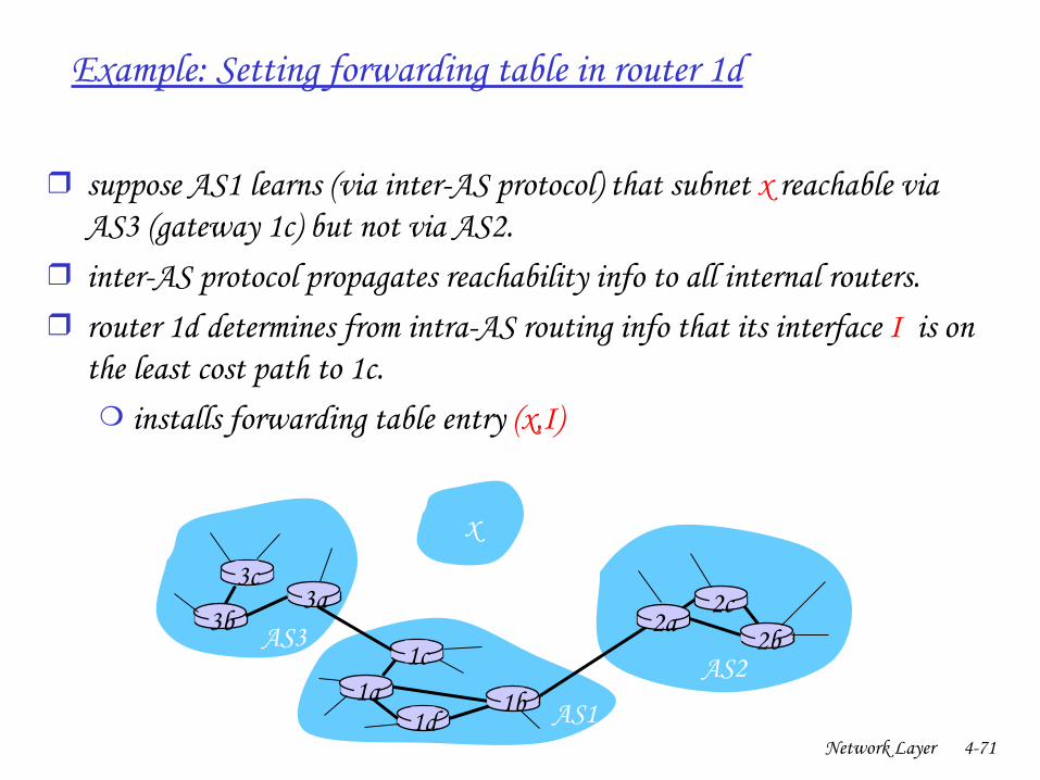
Example: Setting forwarding table in router 1d
❒ suppose AS1 learns (via interAS protocol) that subnet x reachable via AS3 (gateway 1c) but not via AS2.
❒ interAS protocol propagates reachability info to all internal routers.❒ router 1d determines from intraAS routing info that its interface I is on
the least cost path to 1c.❍ installs forwarding table entry (x,I)
3b
1d
3a
1c2aAS3
AS1
AS21a
2c2b
1b
3c
x…
Network Layer 472
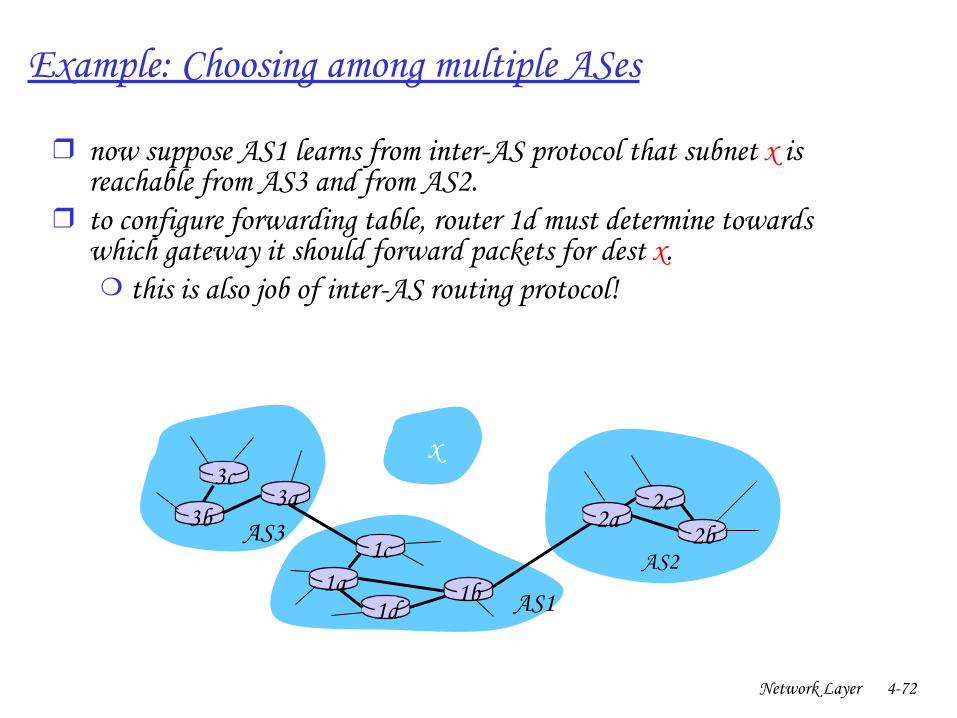
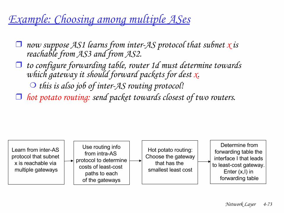
Example: Choosing among multiple ASes
❒ now suppose AS1 learns from interAS protocol that subnet x is reachable from AS3 and from AS2.
❒ to configure forwarding table, router 1d must determine towards which gateway it should forward packets for dest x. ❍ this is also job of interAS routing protocol!
3b
1d
3a
1c2aAS3
AS1
AS21a
2c2b
1b
3cx… …
Network Layer 473
Learn from inter-AS protocol that subnet x is reachable via multiple gateways
Use routing infofrom intra-AS
protocol to determinecosts of least-cost
paths to eachof the gateways
Hot potato routing:Choose the gateway
that has the smallest least cost
Determine fromforwarding table the interface I that leads
to least-cost gateway. Enter (x,I) in
forwarding table
Example: Choosing among multiple ASes
❒ now suppose AS1 learns from interAS protocol that subnet x is reachable from AS3 and from AS2.
❒ to configure forwarding table, router 1d must determine towards which gateway it should forward packets for dest x. ❍ this is also job of interAS routing protocol!
❒ hot potato routing: send packet towards closest of two routers.

Network Layer 474
Chapter 4: Network Layer
❒ 4. 1 Introduction❒ 4.2 Virtual circuit and
datagram networks❒ 4.3 What’s inside a router❒ 4.4 IP: Internet Protocol
❍ Datagram format❍ IPv4 addressing❍ ICMP❍ IPv6
❒ 4.5 Routing algorithms❍ Link state❍ Distance Vector❍ Hierarchical routing
❒ 4.6 Routing in the Internet❍ RIP❍ OSPF❍ BGP
❒ 4.7 Broadcast and multicast routing
Network Layer 475
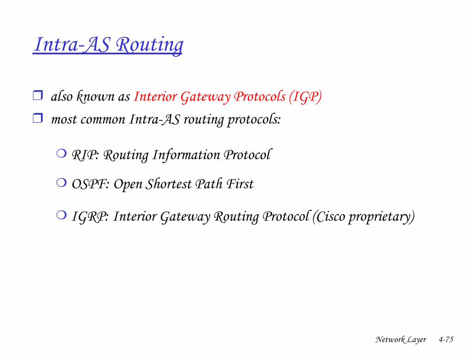
IntraAS Routing
❒ also known as Interior Gateway Protocols (IGP)❒ most common IntraAS routing protocols:
❍ RIP: Routing Information Protocol
❍ OSPF: Open Shortest Path First
❍ IGRP: Interior Gateway Routing Protocol (Cisco proprietary)
Network Layer 476
Chapter 4: Network Layer
❒ 4. 1 Introduction❒ 4.2 Virtual circuit and
datagram networks❒ 4.3 What’s inside a router❒ 4.4 IP: Internet Protocol
❍ Datagram format❍ IPv4 addressing❍ ICMP❍ IPv6
❒ 4.5 Routing algorithms❍ Link state❍ Distance Vector❍ Hierarchical routing
❒ 4.6 Routing in the Internet❍ RIP❍ OSPF❍ BGP
❒ 4.7 Broadcast and multicast routing
Network Layer 477
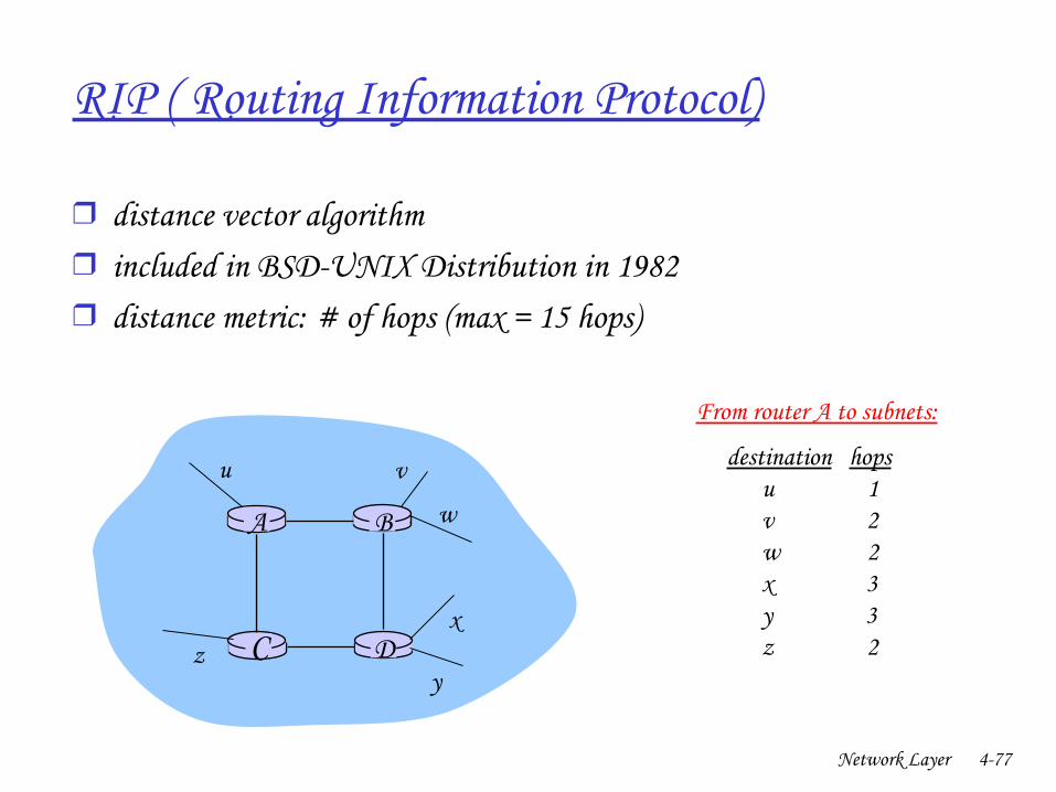
RIP ( Routing Information Protocol)
❒ distance vector algorithm❒ included in BSDUNIX Distribution in 1982❒ distance metric: # of hops (max = 15 hops)
DC
BA
u v
w
x
yz
destination hops u 1 v 2 w 2 x 3 y 3 z 2
From router A to subnets:
Network Layer 478
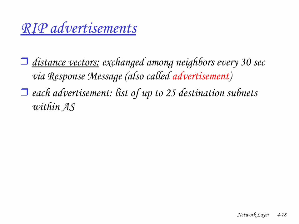
RIP advertisements
❒ distance vectors: exchanged among neighbors every 30 sec via Response Message (also called advertisement)
❒ each advertisement: list of up to 25 destination subnets within AS
Network Layer 479
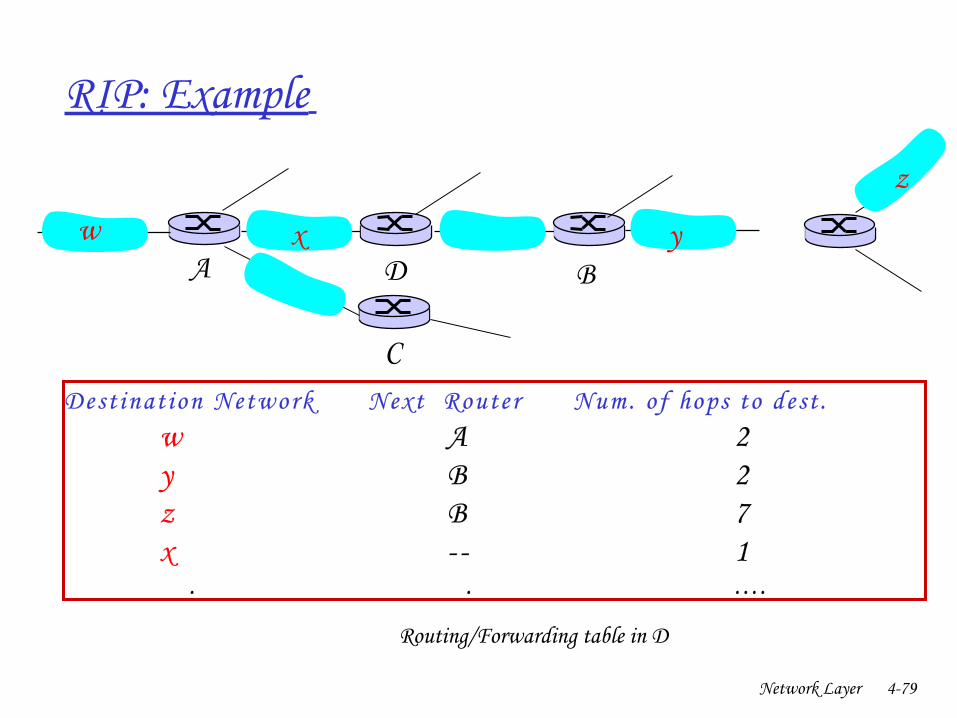
RIP: Example
Dest ination Network Next Router Num. of hops to dest . w A 2
y B 2 z B 7
x 1… . … . . . . .
w x y
z
A
C
D B
Routing/Forwarding table in D
Network Layer 480
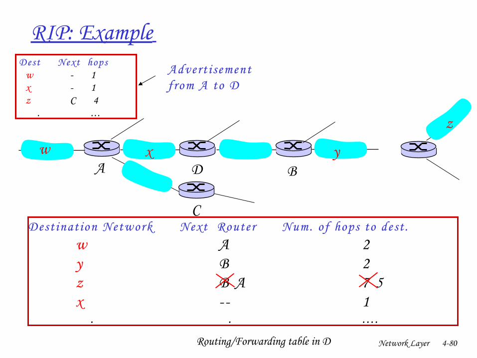
RIP: Example
Dest inat ion Network Next Router Num. of hops to dest . w A 2
y B 2 z B A 7 5
x 1… . … . . . . .
Routing/Forwarding table in D
w x y
z
A
C
D B
Dest Next hops w 1 x 1 z C 4 … . … . . .
Advert i sementfrom A to D
Network Layer 481
RIP: Link Failure and Recovery If no advertisement heard after 180 sec > neighbor/link declared dead
❍ routes via neighbor invalidated❍ new advertisements sent to neighbors❍ neighbors in turn send out new advertisements (if tables changed)❍ link failure info quickly (?) propagates to entire net❍ poison reverse used to prevent pingpong loops (infinite distance =
16 hops)
Network Layer 482
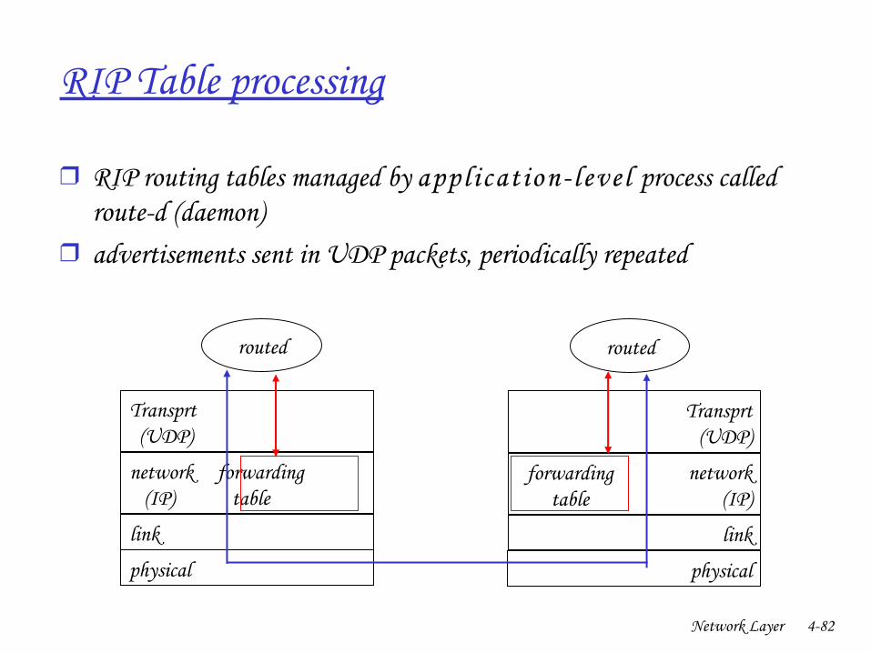
RIP Table processing
❒ RIP routing tables managed by appl icat ion l eve l process called routed (daemon)
❒ advertisements sent in UDP packets, periodically repeated
physical
link
network forwarding (IP) table
Transprt (UDP)
routed
physical
link
network (IP)
Transprt (UDP)
routed
forwardingtable
Network Layer 483
Chapter 4: Network Layer
❒ 4. 1 Introduction❒ 4.2 Virtual circuit and
datagram networks❒ 4.3 What’s inside a router❒ 4.4 IP: Internet Protocol
❍ Datagram format❍ IPv4 addressing❍ ICMP❍ IPv6
❒ 4.5 Routing algorithms❍ Link state❍ Distance Vector❍ Hierarchical routing
❒ 4.6 Routing in the Internet❍ RIP❍ OSPF❍ BGP
❒ 4.7 Broadcast and multicast routing
Network Layer 484
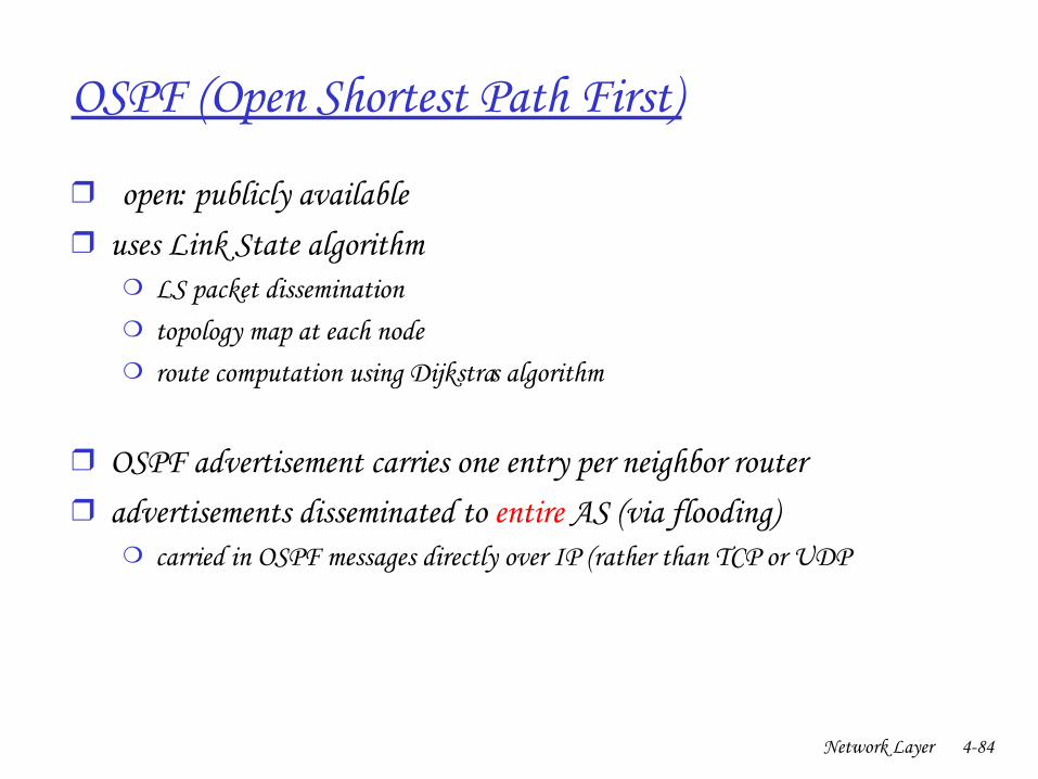
OSPF (Open Shortest Path First)
❒ “ open”: publicly available❒ uses Link State algorithm
❍ LS packet dissemination❍ topology map at each node❍ route computation using Dijkstra’s algorithm
❒ OSPF advertisement carries one entry per neighbor router❒ advertisements disseminated to entire AS (via flooding)
❍ carried in OSPF messages directly over IP (rather than TCP or UDP
Network Layer 485
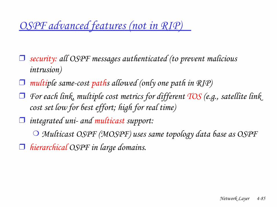
OSPF “advanced” features (not in RIP)
❒ security: all OSPF messages authenticated (to prevent malicious intrusion)
❒ multiple samecost paths allowed (only one path in RIP)❒ For each link, multiple cost metrics for different TOS (e.g., satellite link
cost set “low” for best effort; high for real time)❒ integrated uni and multicast support:
❍ Multicast OSPF (MOSPF) uses same topology data base as OSPF❒ hierarchical OSPF in large domains.
Network Layer 486
Hierarchical OSPF
Network Layer 487
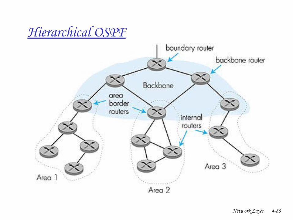
Hierarchical OSPF
❒ twolevel hierarchy: local area, backbone.❍ Linkstate advertisements only in area ❍ each nodes has detailed area topology; only know direction (shortest
path) to nets in other areas.❒ area border routers: “summarize” distances to nets in own area,
advertise to other Area Border routers.❒ backbone routers: run OSPF routing limited to backbone.❒ boundary routers: connect to other AS’s.

Network Layer 488
Chapter 4: Network Layer
❒ 4. 1 Introduction❒ 4.2 Virtual circuit and
datagram networks❒ 4.3 What’s inside a router❒ 4.4 IP: Internet Protocol
❍ Datagram format❍ IPv4 addressing❍ ICMP❍ IPv6
❒ 4.5 Routing algorithms❍ Link state❍ Distance Vector❍ Hierarchical routing
❒ 4.6 Routing in the Internet❍ RIP❍ OSPF❍ BGP
❒ 4.7 Broadcast and multicast routing
Network Layer 489
Internet interAS routing: BGP
❒ BGP (Border Gateway Protocol): the de facto standard❒ BGP provides each AS a means to:
1. Obtain subnet reachability information from neighboring ASs.2. Propagate reachability information to all ASinternal routers.3. Determine “good” routes to subnets based on reachability
information and policy.❒ allows subnet to advertise its existence to rest of
Internet: “I am here”
Network Layer 490
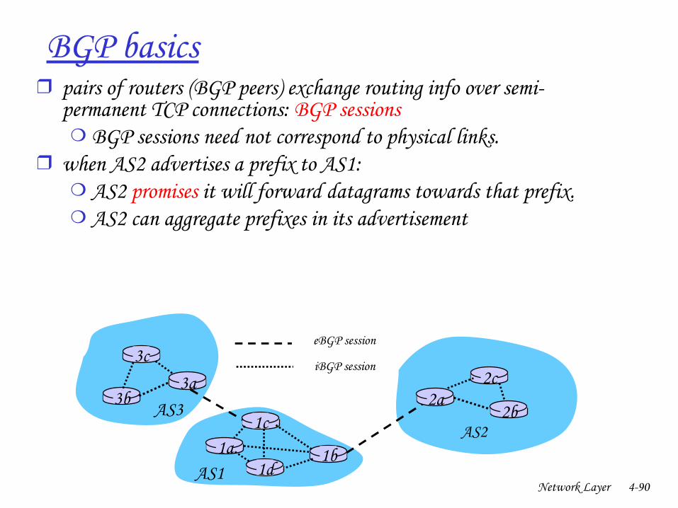
BGP basics❒ pairs of routers (BGP peers) exchange routing info over semi
permanent TCP connections: BGP sessions❍ BGP sessions need not correspond to physical links.
❒ when AS2 advertises a prefix to AS1:❍ AS2 promises it will forward datagrams towards that prefix.❍ AS2 can aggregate prefixes in its advertisement
3b
1d
3a
1c2aAS3
AS1
AS21a
2c
2b
1b
3ceBGP session
iBGP session
Network Layer 491
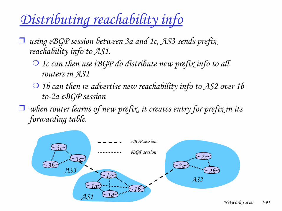
Distributing reachability info❒ using eBGP session between 3a and 1c, AS3 sends prefix
reachability info to AS1.❍ 1c can then use iBGP do distribute new prefix info to all
routers in AS1❍ 1b can then readvertise new reachability info to AS2 over 1b
to2a eBGP session❒ when router learns of new prefix, it creates entry for prefix in its
forwarding table.
3b
1d
3a
1c2aAS3
AS1
AS21a
2c
2b
1b
3ceBGP session
iBGP session
Network Layer 492
Path attributes & BGP routes
❒ advertised prefix includes BGP attributes. ❍ prefix + attributes = “route”
❒ two important attributes:❍ ASPATH: contains ASs through which prefix advertisement has
passed: e.g, AS 67, AS 17 ❍ NEXTHOP: indicates specific internalAS router to nexthop AS.
(may be multiple links from current AS to nexthopAS)❒ when gateway router receives route advertisement, uses
import policy to accept/decline.
Network Layer 493
BGP route selection
❒ router may learn about more than 1 route to some prefix. Router must select route.
❒ elimination rules:1. local preference value attribute: policy decision2. shortest ASPATH 3. closest NEXTHOP router: hot potato routing4. additional criteria
Network Layer 494
BGP routing policy
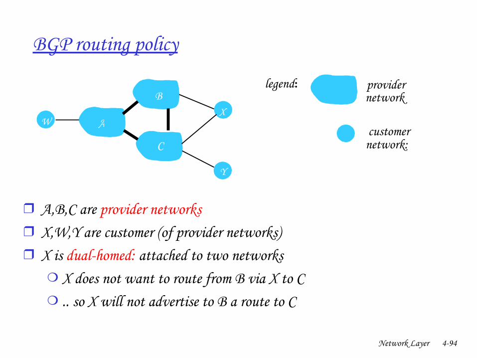
❒ A,B,C are provider networks❒ X,W,Y are customer (of provider networks)❒ X is dualhomed: attached to two networks
❍ X does not want to route from B via X to C❍ .. so X will not advertise to B a route to C
A
B
C
W X
Y
legend:
customer network:
provider network
Network Layer 495
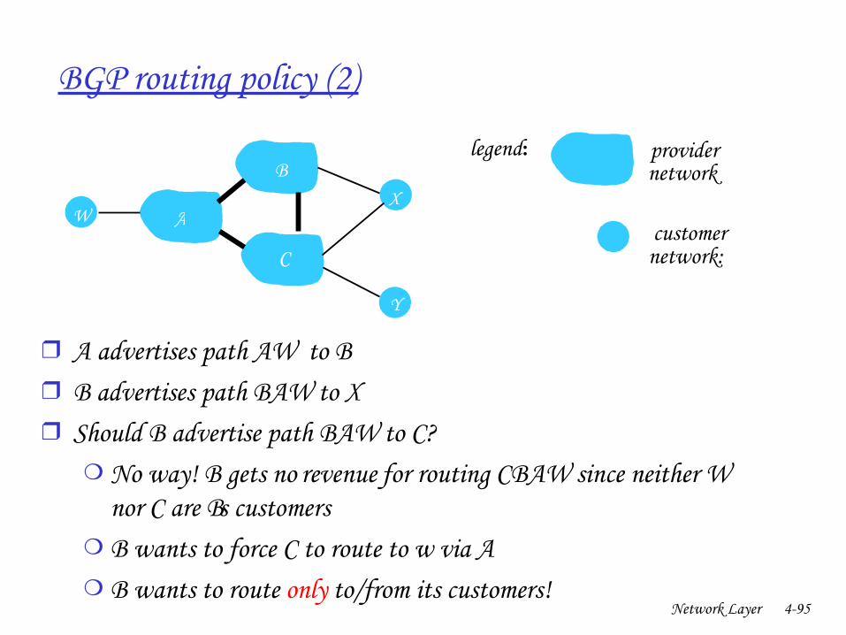
BGP routing policy (2)
❒ A advertises path AW to B❒ B advertises path BAW to X ❒ Should B advertise path BAW to C?
❍ No way! B gets no “revenue” for routing CBAW since neither W nor C are B’s customers
❍ B wants to force C to route to w via A❍ B wants to route only to/from its customers!
A
B
C
W X
Y
legend:
customer network:
provider network
Network Layer 496
Why different Intra and InterAS routing ?
Policy: ❒ InterAS: admin wants control over how its traffic routed, who routes
through its net. ❒ IntraAS: single admin, so no policy decisions needed
Scale:❒ hierarchical routing saves table size, reduced update trafficPerformance: ❒ IntraAS: can focus on performance❒ InterAS: policy may dominate over performance
Network Layer 497
Chapter 4: Network Layer
❒ 4. 1 Introduction❒ 4.2 Virtual circuit and
datagram networks❒ 4.3 What’s inside a router❒ 4.4 IP: Internet Protocol
❍ Datagram format❍ IPv4 addressing❍ ICMP❍ IPv6
❒ 4.5 Routing algorithms❍ Link state❍ Distance Vector❍ Hierarchical routing
❒ 4.6 Routing in the Internet❍ RIP❍ OSPF❍ BGP
❒ 4.7 Broadcast and multicast routing
Network Layer 498
R1
R2
R3 R4
sourceduplication
R1
R2
R3 R4
in-networkduplication
duplicatecreation/transmissionduplicate
duplicate
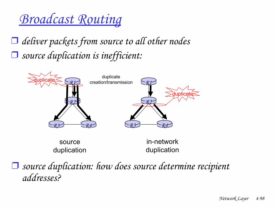
Broadcast Routing❒ deliver packets from source to all other nodes❒ source duplication is inefficient:
❒ source duplication: how does source determine recipient addresses?
Network Layer 499
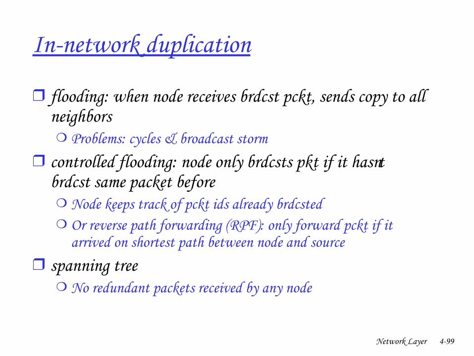
Innetwork duplication
❒ flooding: when node receives brdcst pckt, sends copy to all neighbors❍ Problems: cycles & broadcast storm
❒ controlled flooding: node only brdcsts pkt if it hasn’t brdcst same packet before❍ Node keeps track of pckt ids already brdcsted❍ Or reverse path forwarding (RPF): only forward pckt if it
arrived on shortest path between node and source❒ spanning tree
❍ No redundant packets received by any node
Network Layer 4100
A
B
G
DE
c
F
A
B
G
DE
c
F
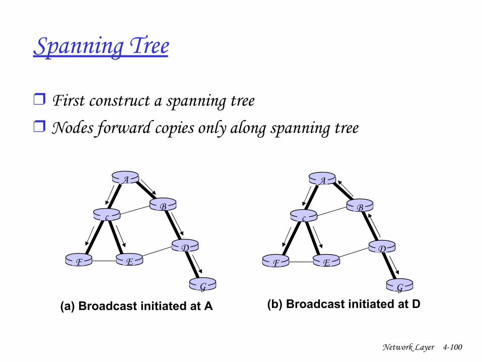
(a) Broadcast initiated at A (b) Broadcast initiated at D
Spanning Tree
❒ First construct a spanning tree❒ Nodes forward copies only along spanning tree
Network Layer 4101
A
B
G
DE
c
F1
2
3
4
5
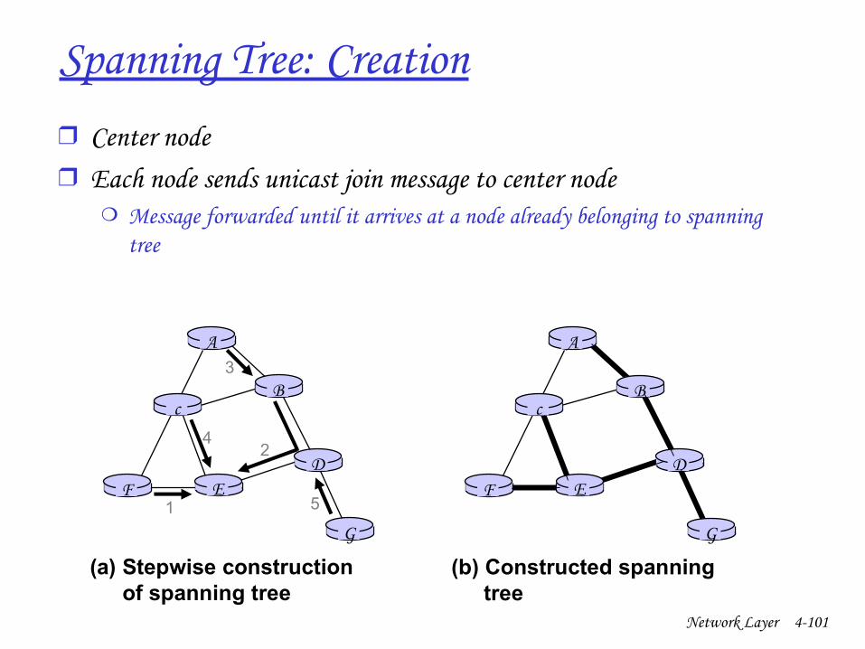
(a) Stepwise construction of spanning tree
A
B
G
DE
c
F
(b) Constructed spanning tree
Spanning Tree: Creation❒ Center node❒ Each node sends unicast join message to center node
❍ Message forwarded until it arrives at a node already belonging to spanning tree
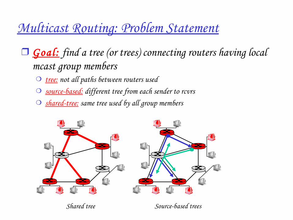
Multicast Routing: Problem Statement❒ Goal : find a tree (or trees) connecting routers having local
mcast group members ❍ tree: not all paths between routers used❍ source-based: different tree from each sender to rcvrs❍ shared-tree: same tree used by all group members
Shared tree Sourcebased trees
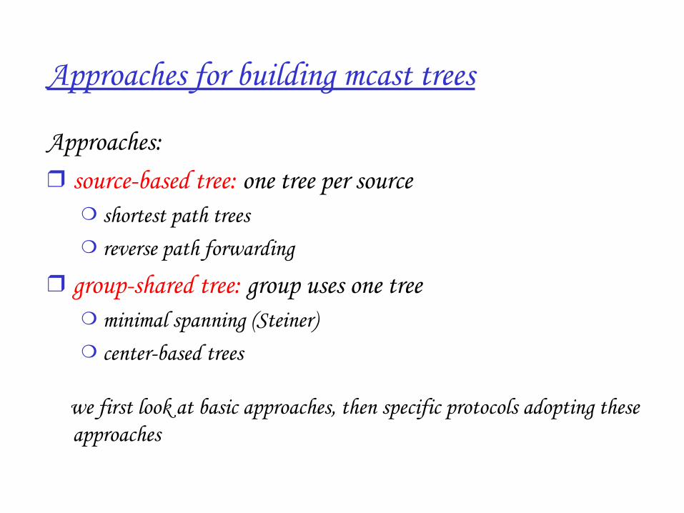
Approaches for building mcast trees
Approaches:❒ sourcebased tree: one tree per source
❍ shortest path trees❍ reverse path forwarding
❒ groupshared tree: group uses one tree❍ minimal spanning (Steiner) ❍ centerbased trees
… we first look at basic approaches, then specific protocols adopting these approaches
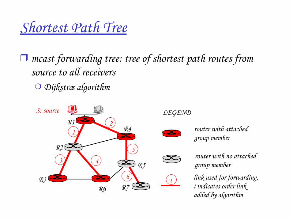
Shortest Path Tree
❒ mcast forwarding tree: tree of shortest path routes from source to all receivers❍ Dijkstra’s algorithm
R1
R2
R3
R4
R5
R6 R7
21
6
3 4
5
i
router with attachedgroup member
router with no attachedgroup member
link used for forwarding,i indicates order linkadded by algorithm
LEGENDS: source
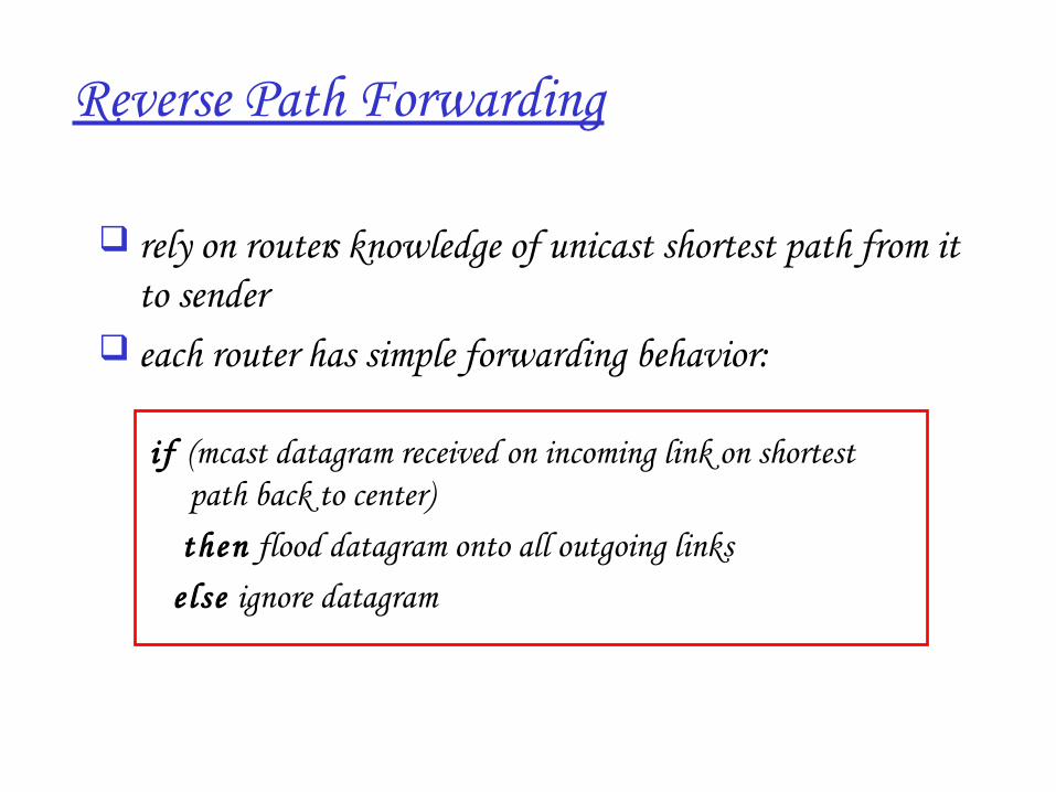
Reverse Path Forwarding
i f (mcast datagram received on incoming link on shortest path back to center)
then flood datagram onto all outgoing links e lse ignore datagram
rely on router’s knowledge of unicast shortest path from it to sender
each router has simple forwarding behavior:
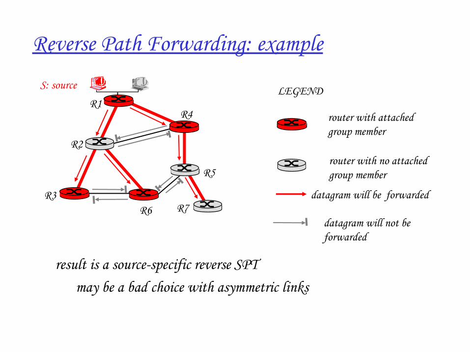
Reverse Path Forwarding: example
• result is a sourcespecific reverse SPT– may be a bad choice with asymmetric links
R1
R2
R3
R4
R5
R6 R7
router with attachedgroup member
router with no attachedgroup member
datagram will be forwarded
LEGENDS: source
datagram will not be forwarded
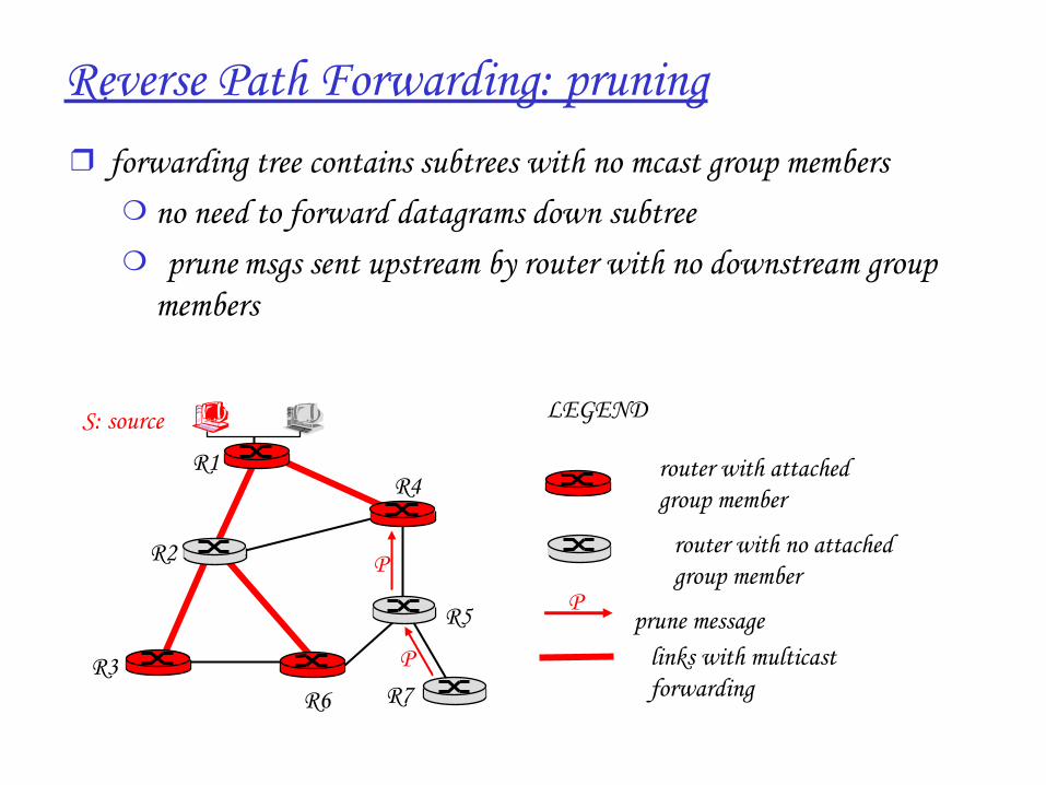
Reverse Path Forwarding: pruning❒ forwarding tree contains subtrees with no mcast group members
❍ no need to forward datagrams down subtree❍ “ prune” msgs sent upstream by router with no downstream group
members
R1
R2
R3
R4
R5
R6 R7
router with attachedgroup member
router with no attachedgroup member
prune message
LEGENDS: source
links with multicastforwarding
P
P
P
SharedTree: Steiner Tree
❒ Steiner Tree: minimum cost tree connecting all routers with attached group members
❒ problem is NPcomplete❒ excellent heuristics exists❒ not used in practice:
❍ computational complexity❍ information about entire network needed❍ monolithic: rerun whenever a router needs to join/leave
Centerbased trees
❒ single delivery tree shared by all❒ one router identified as “center” of tree❒ to join:
❍ edge router sends unicast join-msg addressed to center router❍ join-msg “processed” by intermediate routers and forwarded
towards center❍ join-msg either hits existing tree branch for this center, or
arrives at center❍ path taken by join-msg becomes new branch of tree for this
router
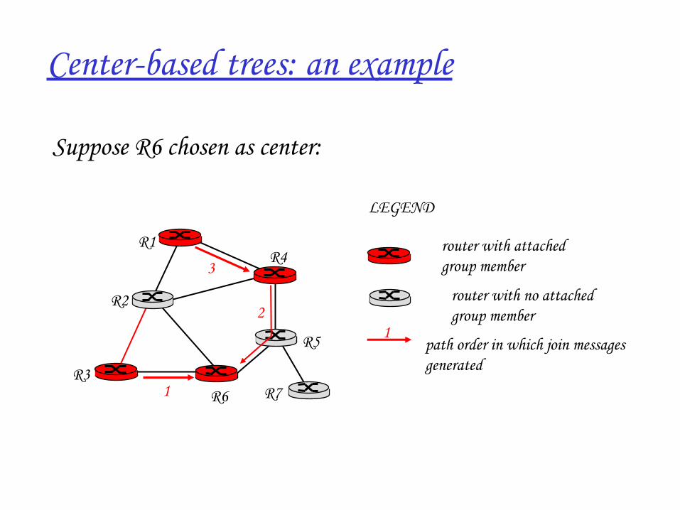
Centerbased trees: an example
Suppose R6 chosen as center:
R1
R2
R3
R4
R5
R6 R7
router with attachedgroup member
router with no attachedgroup member
path order in which join messages generated
LEGEND
21
3
1
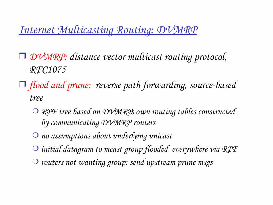
Internet Multicasting Routing: DVMRP
❒ DVMRP: distance vector multicast routing protocol, RFC1075
❒ flood and prune: reverse path forwarding, sourcebased tree❍ RPF tree based on DVMRP’s own routing tables constructed
by communicating DVMRP routers ❍ no assumptions about underlying unicast❍ initial datagram to mcast group flooded everywhere via RPF❍ routers not wanting group: send upstream prune msgs
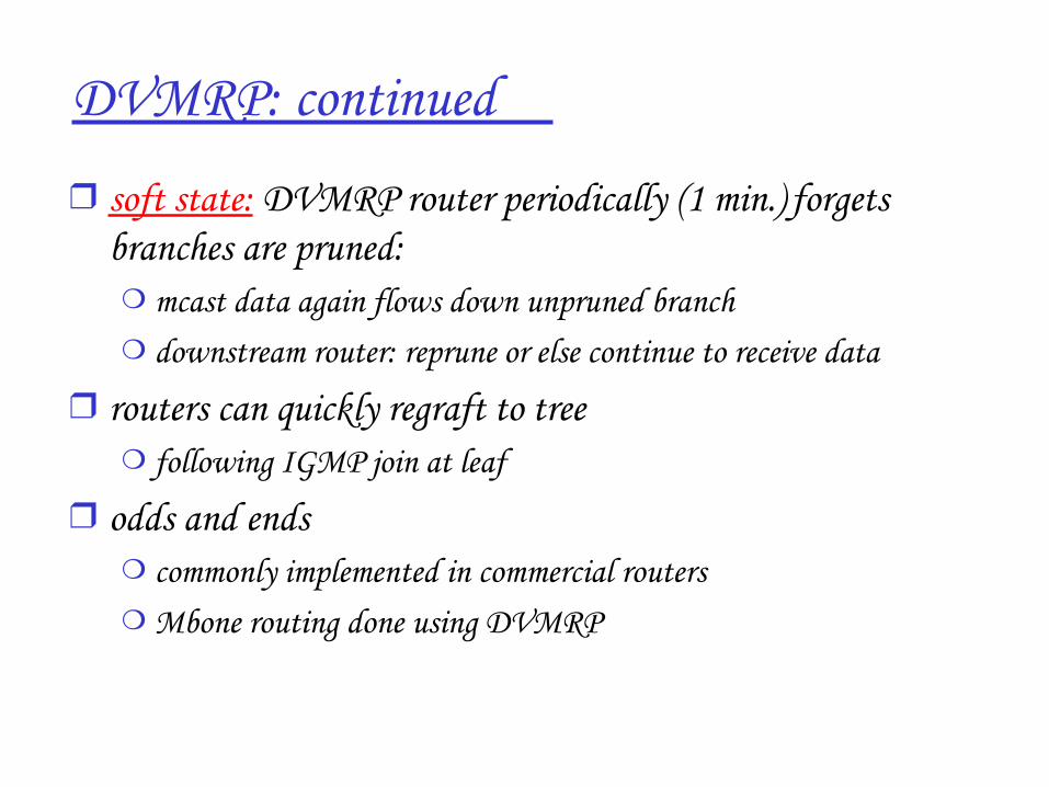
DVMRP: continued…
❒ soft state: DVMRP router periodically (1 min.) “forgets” branches are pruned: ❍ mcast data again flows down unpruned branch❍ downstream router: reprune or else continue to receive data
❒ routers can quickly regraft to tree ❍ following IGMP join at leaf
❒ odds and ends❍ commonly implemented in commercial routers❍ Mbone routing done using DVMRP
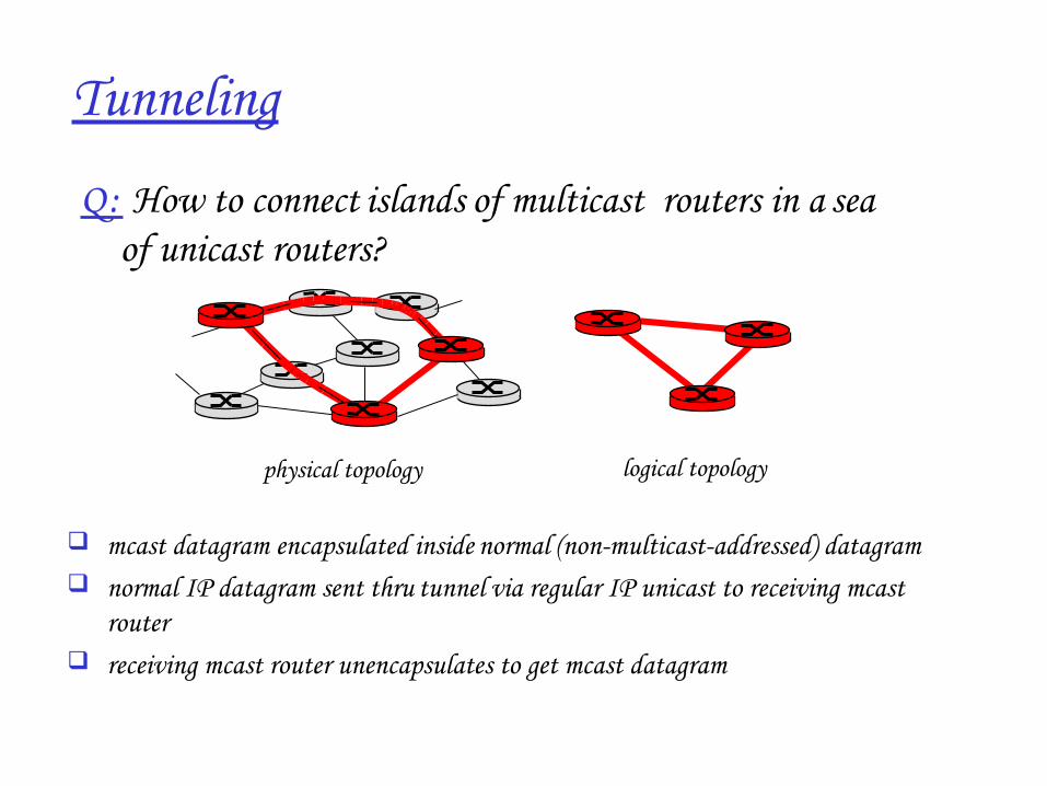
Tunneling
Q: How to connect “islands” of multicast routers in a “sea” of unicast routers?
mcast datagram encapsulated inside “normal” (nonmulticastaddressed) datagram normal IP datagram sent thru “tunnel” via regular IP unicast to receiving mcast
router receiving mcast router unencapsulates to get mcast datagram
physical topology logical topology
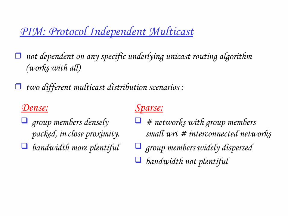
PIM: Protocol Independent Multicast
❒ not dependent on any specific underlying unicast routing algorithm (works with all)
❒ two different multicast distribution scenarios :
Dense: group members densely
packed, in “close” proximity. bandwidth more plentiful
Sparse: # networks with group members
small wrt # interconnected networks group members “widely dispersed” bandwidth not plentiful
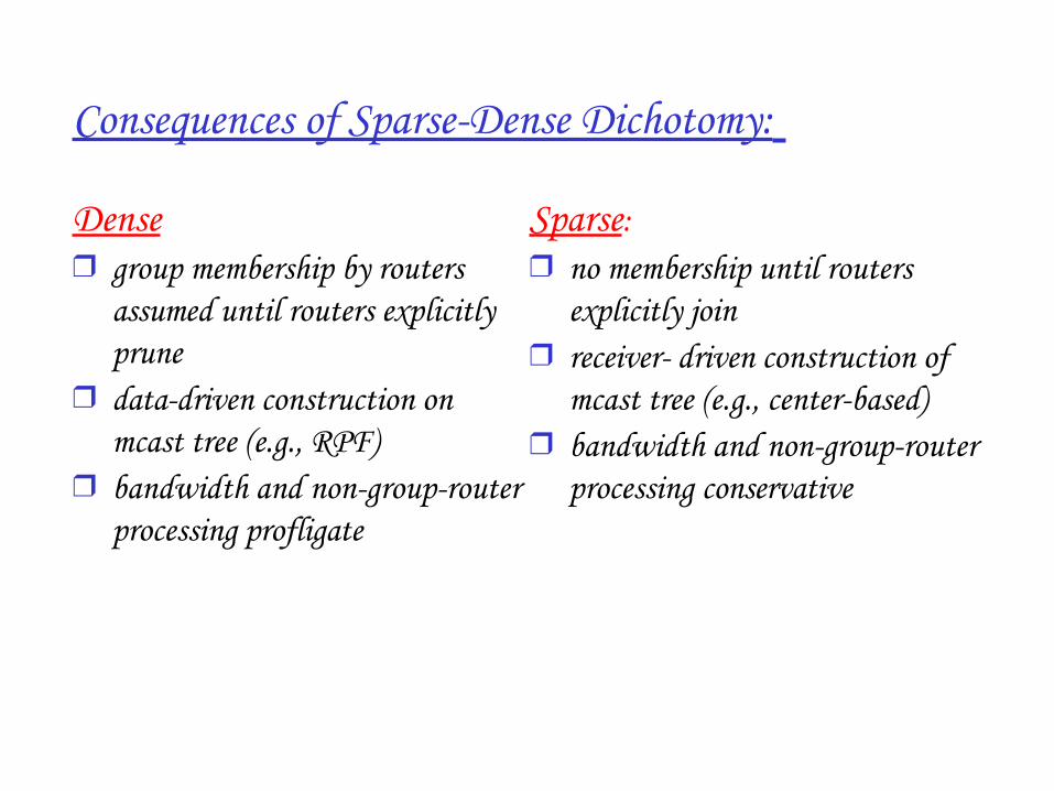
Consequences of SparseDense Dichotomy:
Dense❒ group membership by routers
assumed until routers explicitly prune
❒ data-driven construction on mcast tree (e.g., RPF)
❒ bandwidth and nongrouprouter processing profligate
Sparse:❒ no membership until routers
explicitly join❒ receiver- driven construction of
mcast tree (e.g., centerbased)❒ bandwidth and nongrouprouter
processing conservative
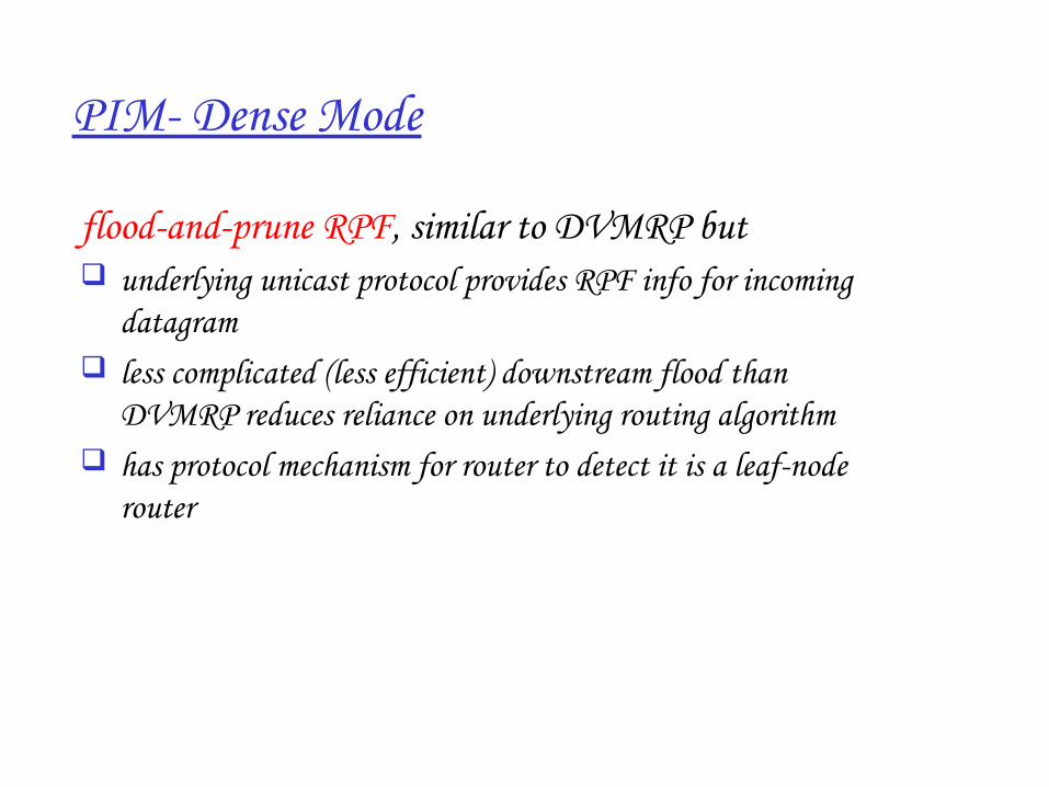
PIM Dense Mode
floodandprune RPF, similar to DVMRP but underlying unicast protocol provides RPF info for incoming
datagram less complicated (less efficient) downstream flood than
DVMRP reduces reliance on underlying routing algorithm has protocol mechanism for router to detect it is a leafnode
router
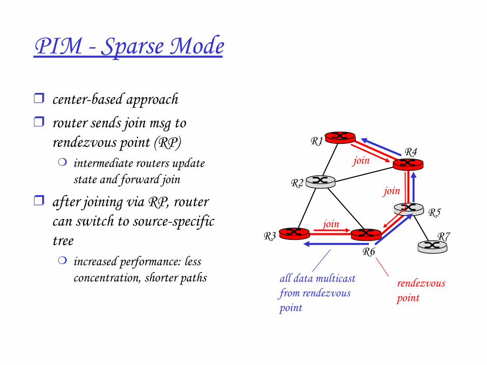
PIM Sparse Mode
❒ centerbased approach❒ router sends join msg to
rendezvous point (RP)❍ intermediate routers update
state and forward join
❒ after joining via RP, router can switch to sourcespecific tree
❍ increased performance: less concentration, shorter paths
R1
R2
R3
R4
R5
R6R7
join
join
join
all data multicastfrom rendezvouspoint
rendezvouspoint
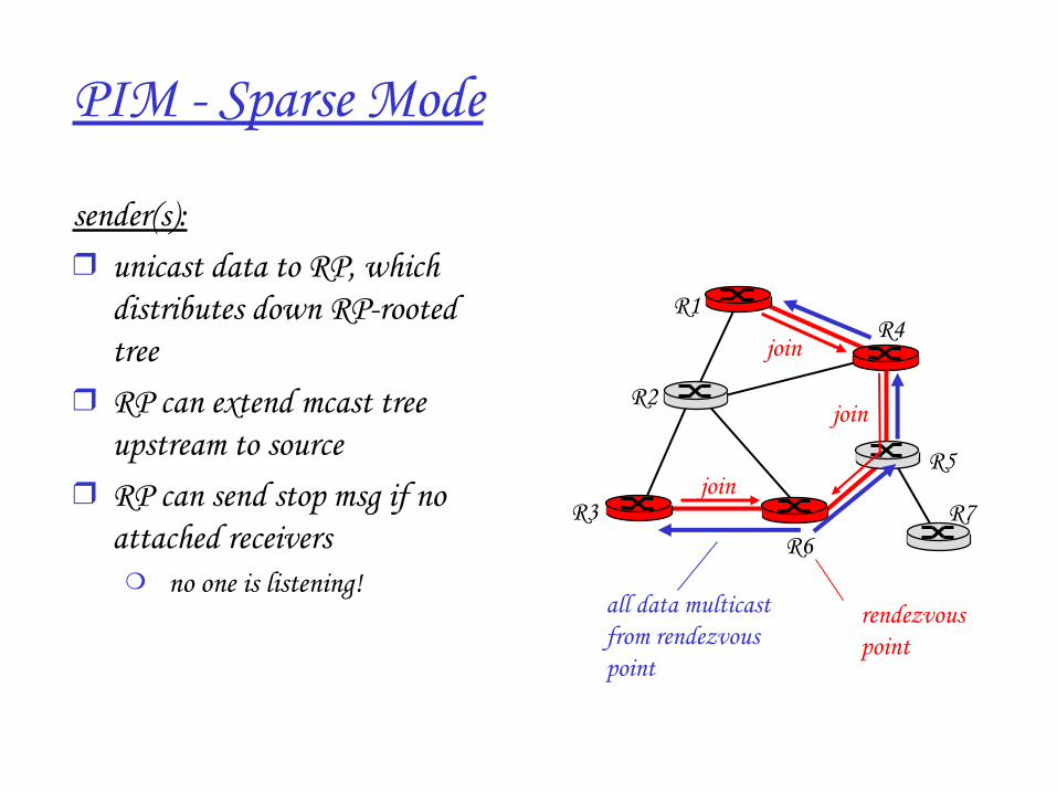
PIM Sparse Mode
sender(s):❒ unicast data to RP, which
distributes down RProoted tree
❒ RP can extend mcast tree upstream to source
❒ RP can send stop msg if no attached receivers
❍ “ no one is listening!”
R1
R2
R3
R4
R5
R6R7
join
join
join
all data multicastfrom rendezvouspoint
rendezvouspoint
Network Layer 4119
Chapter 4: summary
❒ 4. 1 Introduction❒ 4.2 Virtual circuit and
datagram networks❒ 4.3 What’s inside a router❒ 4.4 IP: Internet Protocol
❍ Datagram format❍ IPv4 addressing❍ ICMP❍ IPv6
❒ 4.5 Routing algorithms❍ Link state❍ Distance Vector❍ Hierarchical routing
❒ 4.6 Routing in the Internet❍ RIP❍ OSPF❍ BGP
❒ 4.7 Broadcast and multicast routing

![Http://cs273a.stanford.edu [Bejerano Fall09/10] 1 Milestones due today. Anything to report?](https://img.pdfslide.us/doc/110x75/56649d5a5503460f94a3a39d/httpcs273astanfordedu-bejerano-fall0910-1-milestones-due-today-anything.jpg)


![AVR Architecture [Lect-03 Fall09]](https://img.pdfslide.us/doc/110x75/577dab4c1a28ab223f8c3b24/avr-architecture-lect-03-fall09.jpg)


![Http://cs273a.stanford.edu [Bejerano Fall09/10] 1 Thank you for the midterm feedback!](https://img.pdfslide.us/doc/110x75/56649d745503460f94a53f0c/httpcs273astanfordedu-bejerano-fall0910-1-thank-you-for-the-midterm.jpg)