Embed Size (px)
Citation preview

Copyright © The McGraw-Hill Companies, Inc. Permission required for reproduction or display.4.1
Chapter 4
Network Layer

Copyright © The McGraw-Hill Companies, Inc. Permission required for reproduction or display.4.21.2
4-1 INTRODUCTION
- Figure 4.1 shows the communication
between Alice and Bob at the network
layer.
- This is the same scenario we used in
Chapters 2 and 3 to show the
communication at the application and
the transport layers, respectively.
Copyright © The McGraw-Hill Companies, Inc. Permission required for reproduction or display.4.31.3
Figure 4.1: Communication at the network layer

Copyright © The McGraw-Hill Companies, Inc. Permission required for reproduction or display.4.41.4
Network-Layer Services
The network-layer services that, in general, are
expected from a network-layer protocol.
Packetizing
Routing
Forwarding

Copyright © The McGraw-Hill Companies, Inc. Permission required for reproduction or display.4.51.5
Figure 4.2: Forwarding process
Forwarding
value
B Data
Send the packet�
out of interface 2
B Data

Copyright © The McGraw-Hill Companies, Inc. Permission required for reproduction or display.4.61.6
Packet Switching
- A kind of switching occurs at the network layer
- A router is a switch that creates a connection
between an input port and an output port (or a
set of output ports), just as an electrical switch
connects the input to the output to let electricity
flow.

Copyright © The McGraw-Hill Companies, Inc. Permission required for reproduction or display.4.71.7
Datagram Approach
Virtual-Circuit Approach
Setup Phase
Data-Transfer Phase
Teardown Phase

Copyright © The McGraw-Hill Companies, Inc. Permission required for reproduction or display.4.81.8
Figure 4.3: A connectionless packet-switched network

Copyright © The McGraw-Hill Companies, Inc. Permission required for reproduction or display.4.91.9
Figure 4.4: Forwarding process in a router when used in a
connectionless network
SA DA Data SA DA Data

Copyright © The McGraw-Hill Companies, Inc. Permission required for reproduction or display.4.101.10
Figure 4.5: A virtual-circuit packet-switched network

Copyright © The McGraw-Hill Companies, Inc. Permission required for reproduction or display.4.111.11
Figure 4.6: Forwarding process in a router when used in a virtual
circuit network

Copyright © The McGraw-Hill Companies, Inc. Permission required for reproduction or display.4.121.12
Figure 4.7: Sending request packet in a virtual-circuit network
A to B
A to B
A to B A to B

Copyright © The McGraw-Hill Companies, Inc. Permission required for reproduction or display.4.131.13
Figure 4.8: Sending acknowledgments in a virtual-circuit network

Copyright © The McGraw-Hill Companies, Inc. Permission required for reproduction or display.4.141.14
Figure 4.8: Sending acknowledgments in a virtual-circuit network
Copyright © The McGraw-Hill Companies, Inc. Permission required for reproduction or display.4.151.15
Network-Layer Performance
- The upper-layer protocols that use the service of
the network layer expect to receive an ideal
service, but the network layer is not perfect
- The performance of a network can be measured
in terms of delay, throughput, and packet loss.

Copyright © The McGraw-Hill Companies, Inc. Permission required for reproduction or display.4.161.16
Delay
Throughput
Packet Loss
Transmission Delay
Propagation Delay
Processing Delay
Queuing Delay

Copyright © The McGraw-Hill Companies, Inc. Permission required for reproduction or display.4.171.17
Figure 4.10: Throughput in a path with three links in a series

Copyright © The McGraw-Hill Companies, Inc. Permission required for reproduction or display.4.181.18
Figure 4.11: A path through the Internet backbone

Copyright © The McGraw-Hill Companies, Inc. Permission required for reproduction or display.4.191.19
Figure 4.12: Effect of throughput in shared links

Copyright © The McGraw-Hill Companies, Inc. Permission required for reproduction or display.4.201.20
Structure of A Router
- accepts incoming packets from one of the input
ports (interfaces)
- uses a forwarding table to find the output port
from which the packet departs
- sends the packet from this output port.

Copyright © The McGraw-Hill Companies, Inc. Permission required for reproduction or display.4.211.21
Components
Input Ports
Output Ports
Routing Processor
Switching Fabrics
Crossbar Switch
Banyan Switch
Batcher-Banyan
Switch

Copyright © The McGraw-Hill Companies, Inc. Permission required for reproduction or display.4.221.22
Figure 4.16: Router components
Copyright © The McGraw-Hill Companies, Inc. Permission required for reproduction or display.4.231.23
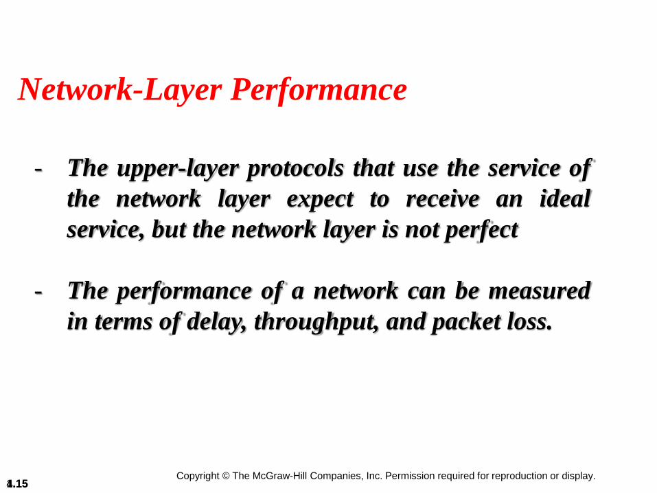
Figure 4.17: Input port

Copyright © The McGraw-Hill Companies, Inc. Permission required for reproduction or display.4.241.24
Figure 4.18: Output port

Copyright © The McGraw-Hill Companies, Inc. Permission required for reproduction or display.4.251.25
Figure 4.19: Crossbar switch

Copyright © The McGraw-Hill Companies, Inc. Permission required for reproduction or display.4.261.26
Figure 4.20: Banyan switch

Copyright © The McGraw-Hill Companies, Inc. Permission required for reproduction or display.4.271.27
Figure 4.21: Examples of routing in a banyan switch

Copyright © The McGraw-Hill Companies, Inc. Permission required for reproduction or display.4.281.28
Figure 4.22: Batcher-banyan switch

Copyright © The McGraw-Hill Companies, Inc. Permission required for reproduction or display.4.291.29
Figure 4.23: Position of IP and other network-layer protocols in
TCP/IP protocol suite

Copyright © The McGraw-Hill Companies, Inc. Permission required for reproduction or display.4.301.30
Figure 4.24: IP datagram

Copyright © The McGraw-Hill Companies, Inc. Permission required for reproduction or display.4.311.31
Figure 4.25: Multiplexing and demultiplexing using the value of
the protocol field

Copyright © The McGraw-Hill Companies, Inc. Permission required for reproduction or display.4.321.32
Figure 4.26: Maximum transfer unit (MTU)

Copyright © The McGraw-Hill Companies, Inc. Permission required for reproduction or display.4.331.33
Figure 4.27: Fragmentation example

Copyright © The McGraw-Hill Companies, Inc. Permission required for reproduction or display.4.341.34
Figure 4.28: Detailed fragmentation example

Copyright © The McGraw-Hill Companies, Inc. Permission required for reproduction or display.4.351.35
Figure 4.29: Three different notations in IPv4 addressing

Copyright © The McGraw-Hill Companies, Inc. Permission required for reproduction or display.4.361.36
Figure 4.30: Hierarchy in addressing

Copyright © The McGraw-Hill Companies, Inc. Permission required for reproduction or display.4.371.37
Figure 4.31: Occupation of the address space in classful addressing

Copyright © The McGraw-Hill Companies, Inc. Permission required for reproduction or display.4.381.38
Figure 4.33: Slash notation (CIDR)

Copyright © The McGraw-Hill Companies, Inc. Permission required for reproduction or display.4.391.39
Figure 4.34: Information extraction in classless addressing

Copyright © The McGraw-Hill Companies, Inc. Permission required for reproduction or display.4.40
A classless address is given as 167.199.170.82/27. We can
find the above three pieces of information as follows. The
number of addresses in the network is 232− n= 25 = 32
addresses. The first address can be found by keeping the
first 27 bits and changing the rest of the bits to 0s.
Example 4.1
The last address can be found by keeping the first 27 bits
and changing the rest of the bits to 1s.

Copyright © The McGraw-Hill Companies, Inc. Permission required for reproduction or display.4.41
We repeat Example 4.1 using the mask. The mask in dotted-
decimal notation is 256.256.256.224 The AND, OR, and
NOT operations can be applied to individual bytes using
calculators and applets at the book website.
Example 4.2

Copyright © The McGraw-Hill Companies, Inc. Permission required for reproduction or display.4.421.42
Figure 4.35: Network address

Copyright © The McGraw-Hill Companies, Inc. Permission required for reproduction or display.4.43
An ISP has requested a block of 1000 addresses. Since 1000
is not a power of 2, 1024 addresses are granted. The prefix
length is calculated as n = 32 − log21024 = 22. An available
block, 18.14.12.0/22, is granted to the ISP. It can be seen
that the first address in decimal is 302,910,464, which is
divisible by 1024.
Example 4.4
Copyright © The McGraw-Hill Companies, Inc. Permission required for reproduction or display.4.44
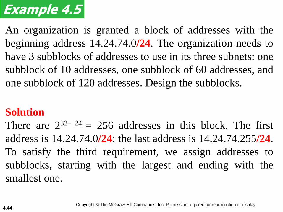
An organization is granted a block of addresses with the
beginning address 14.24.74.0/24. The organization needs to
have 3 subblocks of addresses to use in its three subnets: one
subblock of 10 addresses, one subblock of 60 addresses, and
one subblock of 120 addresses. Design the subblocks.
Example 4.5
Solution
There are 232– 24 = 256 addresses in this block. The first
address is 14.24.74.0/24; the last address is 14.24.74.255/24.
To satisfy the third requirement, we assign addresses to
subblocks, starting with the largest and ending with the
smallest one.

Copyright © The McGraw-Hill Companies, Inc. Permission required for reproduction or display.4.45
a. The number of addresses in the largest subblock, which
requires 120 addresses, is not a power of 2. We allocate 128
addresses. The subnet mask for this subnet can be found as
n1= 32 − log2 128 = 25. The first address in this block is
14.24.74.0/25; the last address is 14.24.74.127/25.
b. The number of addresses in the second largest subblock,
which requires 60 addresses, is not a power of 2 either. We
allocate 64 addresses. The subnet mask for this subnet can
be found as n2 = 32 − log2 64 = 26. The first address in this
block is 14.24.74.128/26; the last address is
14.24.74.191/26.
Example 4.5 (continued)

Copyright © The McGraw-Hill Companies, Inc. Permission required for reproduction or display.4.46
c. The number of addresses in the largest subblock, which
requires 120 addresses, is not a power of 2. We allocate 128
addresses. The subnet mask for this subnet can be found as
n1= 32 − log2 128 = 25. The first address in this block is
14.24.74.0/25; the last address is 14.24.74.127/25.
Example 4.5 (continued)
If we add all addresses in the previous subblocks, the result
is 208 addresses, which means 48 addresses are left in
reserve. The first address in this range is 14.24.74.208. The
last address is 14.24.74.255. We don’t know about the prefix
length yet. Figure 4.36 shows the configuration of blocks.
We have shown the first address in each block.

Copyright © The McGraw-Hill Companies, Inc. Permission required for reproduction or display.4.471.47
Figure 4.36: Solution to Example 4.5

Copyright © The McGraw-Hill Companies, Inc. Permission required for reproduction or display.4.48
Figure 4.37 shows how four small blocks of addresses are
assigned to four organizations by an ISP. The ISP combines
these four blocks into one single block and advertises the
larger block to the rest of the world. Any packet destined for
this larger block should be sent to this ISP. It is the
responsibility of the ISP to forward the packet to the
appropriate organization. This is similar to routing we can
find in a postal network. All packages coming from outside
a country are sent first to the capital and then distributed to
the corresponding destination.
Example 4.6

Copyright © The McGraw-Hill Companies, Inc. Permission required for reproduction or display.4.491.49
Figure 4.37: Example of address aggregation

Copyright © The McGraw-Hill Companies, Inc. Permission required for reproduction or display.4.501.50
Figure 4.38: DHCP message format

Copyright © The McGraw-Hill Companies, Inc. Permission required for reproduction or display.4.511.51
Figure 4.39: Option format

Copyright © The McGraw-Hill Companies, Inc. Permission required for reproduction or display.4.521.52
Figure 4.40: Operation of DHCP

Copyright © The McGraw-Hill Companies, Inc. Permission required for reproduction or display.4.531.53
Figure 4.56: An internet and its graphical representation

Copyright © The McGraw-Hill Companies, Inc. Permission required for reproduction or display.4.541.54
Figure 4.57: Least-cost trees for nodes in the internet of Figure 4.56

Copyright © The McGraw-Hill Companies, Inc. Permission required for reproduction or display.4.551.55
Figure 4.58: Graphical idea behind Bellman-Ford equation

Copyright © The McGraw-Hill Companies, Inc. Permission required for reproduction or display.4.561.56
Figure 4.59: The distance vector corresponding to a tree
Copyright © The McGraw-Hill Companies, Inc. Permission required for reproduction or display.4.571.57
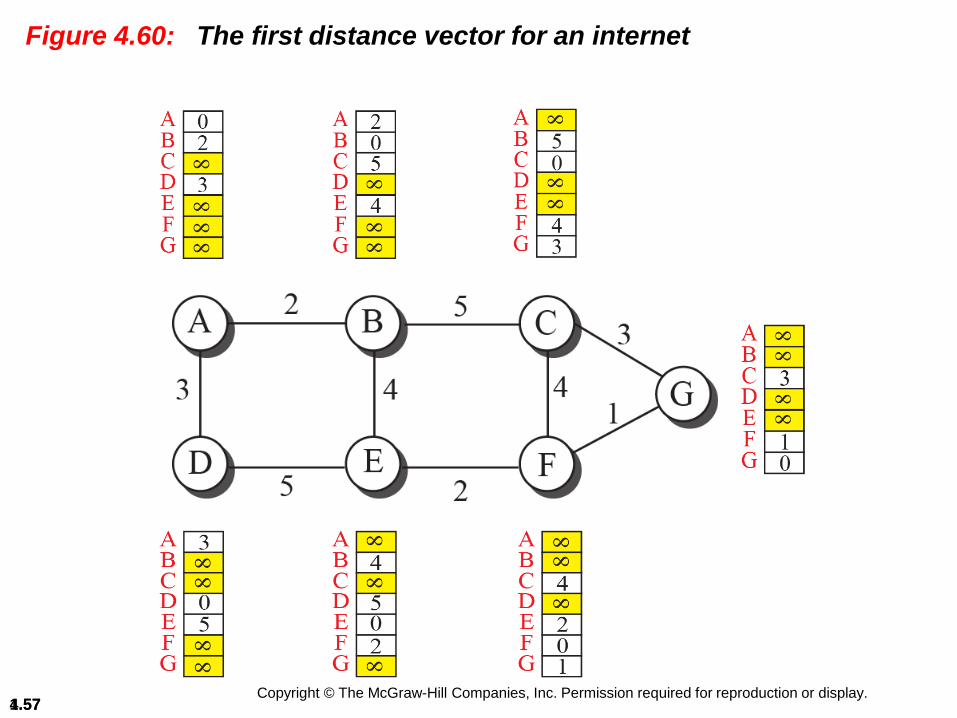
Figure 4.60: The first distance vector for an internet

Copyright © The McGraw-Hill Companies, Inc. Permission required for reproduction or display.4.581.58
Figure 4.61: Updating distance vectors

Copyright © The McGraw-Hill Companies, Inc. Permission required for reproduction or display.4.591.59
Figure 4.62: Two-node instability

Copyright © The McGraw-Hill Companies, Inc. Permission required for reproduction or display.4.601.60
Figure 4.63: Example of a link-state database
Copyright © The McGraw-Hill Companies, Inc. Permission required for reproduction or display.4.611.61
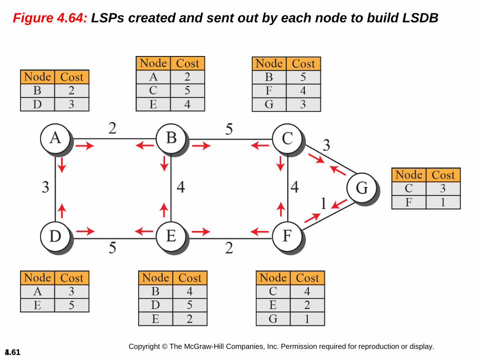
Figure 4.64: LSPs created and sent out by each node to build LSDB

Copyright © The McGraw-Hill Companies, Inc. Permission required for reproduction or display.4.621.62
Figure 4.66: Spanning trees in path-vector routing

Copyright © The McGraw-Hill Companies, Inc. Permission required for reproduction or display.4.631.63
Figure 4.69: Internet structure

Copyright © The McGraw-Hill Companies, Inc. Permission required for reproduction or display.4.641.64
Figure 4.70: Hop counts in RIP
3 hops (N2, N3, N4)
2 hops (N3, N4)
1 hop (N4)

Copyright © The McGraw-Hill Companies, Inc. Permission required for reproduction or display.4.651.65
Figure 4.71: Forwarding tables

Copyright © The McGraw-Hill Companies, Inc. Permission required for reproduction or display.4.661.66
Figure 4.72: RIP message format

Copyright © The McGraw-Hill Companies, Inc. Permission required for reproduction or display.4.67
Figure 4.73 shows a more realistic example of the operation
of RIP in an autonomous system. First, the figure shows all
forwarding tables after all routers have been booted. Then
we show changes in some tables when some update
messages have been exchanged. Finally, we show the
stabilized forwarding tables when there is no more change.
Example 4.15

Copyright © The McGraw-Hill Companies, Inc. Permission required for reproduction or display.4.681.68
Figure 4.73: Example of an autonomous system using RIP (Part I)

Copyright © The McGraw-Hill Companies, Inc. Permission required for reproduction or display.4.691.69
Figure 4.73: Example of an autonomous system using RIP (Part II)

Copyright © The McGraw-Hill Companies, Inc. Permission required for reproduction or display.4.701.70
Figure 4.73: Example of an autonomous system using RIP (Part III)
Copyright © The McGraw-Hill Companies, Inc. Permission required for reproduction or display.4.711.71
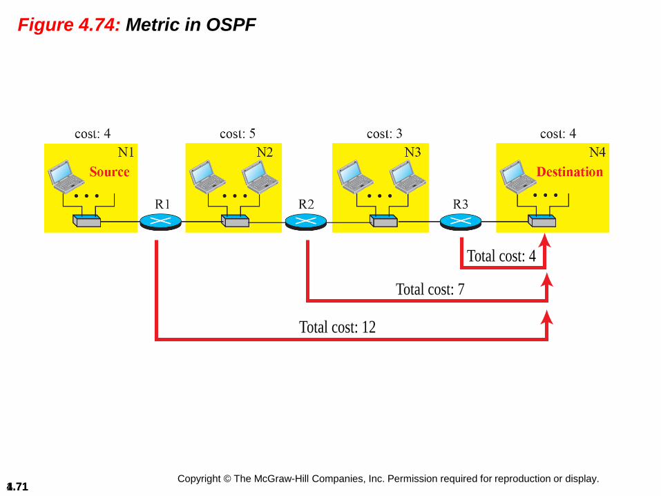
Figure 4.74: Metric in OSPF
Total cost: 12
Total cost: 7
Total cost: 4

Copyright © The McGraw-Hill Companies, Inc. Permission required for reproduction or display.4.721.72
Figure 4.75: Forwarding tables in OSPF

Copyright © The McGraw-Hill Companies, Inc. Permission required for reproduction or display.4.731.73
Figure 4.76: Areas in an autonomous system

Copyright © The McGraw-Hill Companies, Inc. Permission required for reproduction or display.4.741.74
Figure 4.77: Five different LSPs (Part I)

Copyright © The McGraw-Hill Companies, Inc. Permission required for reproduction or display.4.751.75
Figure 4.77: Five different LSPs (Part II)

Copyright © The McGraw-Hill Companies, Inc. Permission required for reproduction or display.4.761.76
Figure 4.78: OSPF message formats (Part I)
Attention
Copyright © The McGraw-Hill Companies, Inc. Permission required for reproduction or display.4.771.77
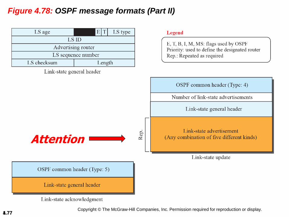
Figure 4.78: OSPF message formats (Part II)
Attention

Copyright © The McGraw-Hill Companies, Inc. Permission required for reproduction or display.4.781.78
Figure 4.79: A sample internet with four ASs

Copyright © The McGraw-Hill Companies, Inc. Permission required for reproduction or display.4.791.79
Figure 4.80: eBGP operation

Copyright © The McGraw-Hill Companies, Inc. Permission required for reproduction or display.4.801.80
Figure 4.81: Combination of eBGP and iBGP sessions in our internet

Copyright © The McGraw-Hill Companies, Inc. Permission required for reproduction or display.4.811.81
Figure 4.82: Finalized BGP path tables (Part I)

Copyright © The McGraw-Hill Companies, Inc. Permission required for reproduction or display.4.821.82
Figure 4.82: Finalized BGP path tables (Part II)

Copyright © The McGraw-Hill Companies, Inc. Permission required for reproduction or display.4.831.83
Figure 4.82: Finalized BGP path tables (Part III)

Copyright © The McGraw-Hill Companies, Inc. Permission required for reproduction or display.4.841.84
Figure 4.83: Forwarding tables after injection from BGP (Part I)

Copyright © The McGraw-Hill Companies, Inc. Permission required for reproduction or display.4.851.85
Figure 4.83: Forwarding tables after injection from BGP (Part II)

Copyright © The McGraw-Hill Companies, Inc. Permission required for reproduction or display.4.861.86
Figure 4.84: Format of path attribute

Copyright © The McGraw-Hill Companies, Inc. Permission required for reproduction or display.4.871.87
Figure 4.85: Flow diagram for route selection

Copyright © The McGraw-Hill Companies, Inc. Permission required for reproduction or display.4.881.88
Figure 4.86: BGP messages


![Data Sheet - Microchip Technologyww1.microchip.com/downloads/en/DeviceDoc/25093B.pdf · P0[7:0] I/O Port 0: Port 0 is an 8-bit open drain bi-directional I/O port. As an output port](https://img.pdfslide.us/doc/110x75/5ab0dfad7f8b9a284c8bc8d4/data-sheet-microchip-70-io-port-0-port-0-is-an-8-bit-open-drain-bi-directional.jpg)