Embed Size (px)
Citation preview

CHAPTER 4 Facility Requirements Final 2013
Southwest Oregon Regional Airport
Master Plan Update 4-1
CHAPTER 4 FACILITY REQUIREMENTS
4.1 INTRODUCTION
To properly plan for the future requirements of Southwest Oregon Regional Airport, it is necessary to translate the forecasts of aviation demand into the specific types and quantities of facilities that are projected to be needed. The demand for new or expanded facilities is often driven by capacity shortfalls that leave an airport unable to accommodate forecast growth with existing facilities. However, the requirements for new or improved facilities can also be driven by other circumstances. For example, facilities may be needed to comply with updated standards developed and adopted by the FAA or other regulatory agencies, accommodate the strategic vision for the Airport, or replace outdated or inefficient facilities that are prohibitively costly to maintain or modernize. These circumstances can have a significant impact on future needs and have been considered in this analysis for the Airport. The findings of the capacity analyses and facility requirement determinations form the foundation for the identification of development alternatives in subsequent chapters of this plan. Evaluation of those alternatives will allow Airport staff to create a development plan to meet future demand. Critical future investment decisions will be based on these analyses. The facility requirements analysis begins with a review of emerging industry trends that may influence the need for future facilities. The remaining portion of this chapter is devoted to assessment of each of the following major issues and functional facility areas of Southwest Oregon Regional Airport:
Emerging Trends
Meteorological Conditions
Airport Design Classifications
Airfield Design
Airspace, Navigational Aids, and Visual Aids Requirements
Passenger Terminal Area
Vehicle Access, Circulation, and Parking Requirements
Aviation Support Facilities Requirements This chapter concludes with a section that summarizes the key findings of the facility requirement assessments that will be carried forward to the identification and evaluation of alternatives.

CHAPTER 4 Facility Requirements Final 2013
Southwest Oregon Regional Airport
Master Plan Update 4-2
4.2 EMERGING TRENDS
The aviation industry is changing rapidly and this evolution may have a significant impact on the size, quantity, and type of facilities needed to accommodate future demand. The rapid pace of change in the aviation industry is expected to continue. All airport master planning efforts should examine industry trends and identify those that will influence their capacity needs. Some of the emerging trends in the aviation industry that should be considered in the master plan for Southwest Oregon Regional Airport include:
Airports may need to develop additional revenue streams beyond traditional aviation-related revenues from landing fees, terminal rentals, hangar leases, and fuel taxes. This can be accomplished by developing alternative uses for airport property that is surplus to current aviation-related functions.
There is a growing need for airports to find ways for optimizing concessions programs/facilities in terminal buildings.
The design and layout of terminal buildings is evolving as new technology and security requirements are altering the relationships between the airport, airlines, and passengers.
Sustainability initiatives are pushing airports toward energy-efficient and environmentally responsive facilities. Advances in construction techniques and increasing awareness of operational impacts have resulted in the adoption of green building practices.
A major revision to the FAA Advisory Circular (AC) 150/5300-13, Airport Design is expected to be published in September 2012. The Draft AC 150/5300-13A was released in May 2, 2012, and includes AC design standard changes that address airfield safety and airfield design. A significant portion of design guidance published in FAA Engineering Brief (EB) No. 75: Incorporation of Runway Incursion Prevention into Taxiway and Apron Design, will be incorporated as design standards into AC 150/5300-13A, likely rendering EB No. 75 obsolete after the AC revision is published. These changes may drive some changes to the geometry of key airfield features and land acquisition strategies.
In general, many of the emerging trends in the aviation industry focus on the implementation of technology, lowering operational cost for airport facilities while at the same time reducing environmental impacts. The other major influence will be an increasing need to expand airport revenue streams beyond the traditional aviation related activities.

CHAPTER 4 Facility Requirements Final 2013
Southwest Oregon Regional Airport
Master Plan Update 4-3
4.3 METEOROLOGICAL CONDITIONS
Climate conditions have an influence on aircraft performance, as well as airfield dimensional and separation standards. Temperature, precipitation, winds, visibility, and typical cloud ceiling heights are important climate factors used to assess weather conditions and the aircraft operational impacts associated with use of Runways 04/22 and 13/31. 4.3.1 Climate Summary
The average annual temperature for North Bend is 52° Fahrenheit (F), ranging from 66°F in August and September to 39°F in January. On average the temperature exceeds 80°F six days annually, and exceeds 60°F (standard temperature) more than 152 days. The average annual precipitation is 61.9 inches. On average, visual flight rules (VFR) conditions (ceiling of at least 1,000 feet and visibility of at least three miles) are experienced over 86 percent of the time (316 days), while instrument flight rules (IFR) conditions (ceiling of less than 1,000 feet or visibility of less than three miles) occurred within the remaining 14 percent (49 days) of the year. 4.3.2 Runway Orientation and Wind Analysis
Runway wind coverage analysis was conducted using the FAA’s Airports GIS Airport Design Tools Wind Analysis, with data supplied by National Climatic Data Center from the weather reporting station at Southwest Oregon Regional Airport during the period from 2000 through 2009. FAA planning standards recommend that the runway system provide a minimum of 95 percent wind coverage. If a single runway cannot provide this level of coverage, then a crosswind runway is warranted. As shown in Figure 4-1, Runway 04/22 provides 82.50 percent or better wind coverage for all-weather conditions with a 10.5 knot crosswind component, while Runway 13/31 provides 92.79 percent or better wind coverage. When combined, Runway 04/22 and Runway 13/31 provide 97.14 percent wind coverage during all-weather conditions with a 10.5 knot crosswind component. During inclement weather conditions, Runway 04/22 provides 88.15 percent or better instrument flight rules (IFR) wind coverage with a 10.5 knot crosswind component, while Runway 13/31 provides at least 94.15 percent. The current runway configuration is adequate in respect to providing sufficient wind coverage; however, neither Runway 04/22 nor Runway 13/31 can independently provide the FAA recommended 95 percent all-weather or IFR wind coverage for the 10.5 knot crosswind component. Consequently, both runways are important to maintain at present design standards to ensure adequate wind coverage.

CHAPTER 4 Facility Requirements Final 2013
Southwest Oregon Regional Airport
Master Plan Update 4-4
Table 4-1 ALL WEATHER AND IFR WIND COVERAGE
Source: National Oceanic and Atmospheric Administration, Observation Period 2000-2009, Station 72691, North Bend, Oregon.
Figure 4-1 ALL WEATHER WIND ROSE
Sources: National Oceanic and Atmospheric Administration, Observation Period 2000-2009, Station 72691, North Bend, OR; FAA All Weather Wind Rose Form; and RS&H, 2012.
10.5 Knots 13 Knots 16 Knots 20 Knots
Runway (% Component) (% Component) (% Component) (% Component)
Runway 04/22 82.50% 87.72% 93.53% 97.55%
Runway 13/31 92.79% 96.40% 98.98% 99.76%
Combined Runways 97.14% 98.99% 99.79% 99.98%
10.5 Knots 13 Knots 16 Knots 20 Knots
Runway (% Component) (% Component) (% Component) (% Component)
Runway 04/22 88.15% 93.15% 97.55% 99.31%
Runway 13/31 94.15% 97.04% 99.00% 99.75%
Combined Runways 98.02% 99.36% 99.86% 99.97%
Wind Coverage Provided Under All-Weather Conditions
Wind Coverage Provided Under IFR Conditions

CHAPTER 4 Facility Requirements Final 2013
Southwest Oregon Regional Airport
Master Plan Update 4-5
4.4 AIRPORT DESIGN CLASSIFICATION
Airport design classification identifies the FAA’s Airport Reference Code (ARC) and critical aircraft for the Airport expected during this planning period (2010-2030). This section identifies the airport’s national role and service level, the ARC, critical aircraft, and related airport design standards. 4.4.1 Airport Role and Service Level
Southwest Oregon Regional Airport is identified in the FAA’s National Plan of Integrated Airports
System (NPIAS) as a Primary/Non-Hub commercial service facility. A Primary/Non-Hub, as
defined by the FAA, is a commercial service airport that accommodates more than 10,000 annual
passenger enplanements, but less than 0.05 percent of total annual U.S. passenger
enplanements. Currently, within the NPIAS there are 244 Non-Hub airports in the U.S., based
upon the 2011-2015 NPIAS Report. According to the FAA Terminal Area Forecast, the Airport
enplaned approximately 22,585 passengers in 2010, and is projected to remain a Non-Hub facility
throughout the 20-year airport master planning horizon. The 2011-2015 NPIAS Report indicates
that the largest Non-Hub airport enplaned approximately 367,874 passengers. This classification
is used for FAA planning and funding purposes.
4.4.2 Airport Design Classification and Airport Reference Code (ARC)
The Airport Reference Code (ARC) is a system developed by the FAA to relate facility design criteria to the operational and physical characteristics of the airplane types that will operate at a particular airport. The ARC has two components relating to the airport design aircraft. The first component, depicted by a letter, is the Aircraft Approach Category (AAC) and relates to aircraft approach speed. The second component, depicted by a Roman numeral, is the Airplane Design Group (ADG) and relates to airplane wingspan and tail height. In the case of ADG I, an additional designation of “small aircraft only” relates to aircraft with maximum gross weights of 12,500 pounds or less. Generally, aircraft approach speed applies to runway length and related features. Airplane wingspan and tail height primarily relates to runway-taxiway separation and width criteria. Airports expected to accommodate only small piston-engine airplanes normally fall into ARC A-I or B-I. Airports serving larger general aviation and commuter-type planes are usually ARC B-II or B-III. Small to medium-sized airports serving air carriers are usually ARC C-III, while larger air carrier airports are usually ARC D-IV or D-V. The elements that comprise the ARC are described below.
Aircraft Approach Category (ACC) - A grouping of aircraft based on 1.3 times the aircraft stall speed in landing configuration at the maximum certificated landing weight. The categories are as follows:
Category A: Approach speed less than 91 knots
Category B: Approach speed 91 knots or more but less than 121 knots
Category C: Approach speed 121 knots or more but less than 141 knots
Category D: Approach speed 141 knots or more but less than 166 knots
Category E: Approach speed 166 knots or more

CHAPTER 4 Facility Requirements Final 2013
Southwest Oregon Regional Airport
Master Plan Update 4-6
Airplane Design Group (ADG) - A grouping of airplanes based on wingspan or tail height. When wingspan and tail height place an aircraft in two different groups, the more demanding group is used. The groups are as follows:
Group I: Up to but not including 49 feet (15 m) wingspan or tail height up to but not including 20 feet
Group II: 49 feet (15 m) up to but not including 79 feet (24 m) wingspan or tail height from 20 up to but not including 30 feet
Group III: 79 feet (24 m) up to but not including 118 feet (36 m) wingspan or tail height from 30 up to but not including 45 feet
Group IV: 118 feet (36 m) up to but not including 171 feet (52 m) wingspan or tail height from 45 up to but not including 60 feet
Group V: 171 feet (52 m) up to but not including 214 feet (65 m) wingspan or tail height from 60 up to but not including 66 feet
Group VI: 214 feet (65 m) up to but not including 262 feet (80 m) wingspan or tail height from 66 up to but not including 80 feet
The forecast of operations by Airport Reference Code for the years 2010 through 2030 is provided in Figure 4-2. Key conclusions that can be reached from this projection are:
The majority of aircraft operations will remain in the A-I/B-I and A-II/B-II segments; however, the growth in the A-I/B-I segment is nominal. This mirrors the nationwide trend in the decreased utilization of small piston-powered aircraft.
The least amount of operations will be conducted by Airplane Design Group III aircraft. The A-III/B-III segments are expected to decline, while the C-III/D-III segment is expected to slightly increase while maintaining their existing share of operations. Although this segment is declining, the majority of ADG III operations occur during the peak summer months.
Operations within the A-II/B-II, C-I/D-I, and C-II/D-II segments will continue to grow at a steady rate and increase their share of total projected aircraft operations.

CHAPTER 4 Facility Requirements Final 2013
Southwest Oregon Regional Airport
Master Plan Update 4-7
Figure 4-2 20-YEAR TOTAL AIRCRAFT OPERATIONS GROWTH
Source: Reynolds, Smith and Hills, Inc., 2012. Note: Totals may differ slightly due to rounding.
0.42%
0.46%
0.49%
0.51%
0.0%
0.1%
0.2%
0.3%
0.4%
0.5%
0.6%
20,000
20,500
21,000
21,500
22,000
22,500
23,000
23,500
2010 2015 2020 2025 2030
Total Ops Year Over Year % Change Linear (Total Ops)
A-I/B-I A-II/B-II A-III/B-III C-I/D-I C-II/D-II C-III/D-III C-IV/D-IV Total
2010 8,835 6,521 210 2,104 3,155 210 0 21,035
2015 8,915 6,767 215 2,148 3,222 215 0 21,482
2020 9,013 6,924 220 2,198 3,407 220 0 21,982
2025 9,121 7,207 113 2,252 3,603 225 0 22,521
2030 9,357 7,393 116 2,310 3,696 231 0 23,103
Compound Annual Growth Rate 0.5%

CHAPTER 4 Facility Requirements Final 2013
Southwest Oregon Regional Airport
Master Plan Update 4-8
To determine the design standards for a particular airport or airport facility, the ARC for the largest family of aircraft conducting (or expected to conduct) at least 500 annual operations (combination of takeoffs and landings) at the airport is identified as the critical aircraft. This critical aircraft, described by approach speed, wingspan, and tail height, serves as the basis for determining the Airport’s design, structure, and equipment needs for airfield, runway, and terminal area facilities. As discussed in Chapter 3, Aviation Demand Forecast, the previous master plan study determined that the “most demanding” type of aircraft at the Airport is the Bombardier Dash 8-200 (A-III). While commercial jet service was initiated during the summer months of 2011 with the 50-seat Bombardier CRJ-200 regional jet aircraft (C-II), the current scheduled commercial service aircraft is the Embraer E-120 Brasilia (B-II),. Corporate jets using the Airport typically fall within the ARC B-I through D-III categories. Airport landing records indicate corporate jet operations conducted by a variety of aircraft, such as the Falcon 50 (B-II), Bombardier Global Express (C-III), and the Gulfstream V (D-III). Corporate jet operations in the Airplane Design Group III category occur more frequently during the peak summer months, a trend that is expected to continue throughout the planning period. (See Appendix E, Business Jet Data, for a list of business jet aircraft characteristics, including Airport Reference Codes). The forecast chapter, as approved by the FAA, concludes that the CRJ-200 will be the critical aircraft for Southwest Oregon Regional Airport. It is important to note that specific areas of an airport can be identified to accommodate various categories of aircraft. That is, each runway or aircraft movement area may be designated for a different type aircraft. For example, one runway may be designed to accommodate general aviation aircraft and another designed to serve commercial services aircraft. Based on the expected operations by Airport Reference Code, Table 4-2 identifies the existing and future ARC designated for Runways 04/22 and 13/31 at Southwest Oregon Regional Airport. The existing ARC for both Runways 04/22 and 13/31 is B-III. Prior planning documents indicate the future ARC for Runway 04/22 is C-III, and in 2009 the parallel taxiway serving the primary runway (Taxiway C) was relocated to meet ARC C-III design standards. Based on the expected aircraft operational forecast and previous planning and design, the future ARC for Runway 04/22 will remain C-III, and the ARC for Runway 13/31 is expected to remain as B-III.

CHAPTER 4 Facility Requirements Final 2013
Southwest Oregon Regional Airport
Master Plan Update 4-9
Table 4-2
AIRPORT REFERENCE CODE – EXISTING AND FUTURE
Sources: FAA Advisory Circular 150/5300-13 and Reynolds, Smith, and Hills Inc., 2012.
Note: Combined, the 'approach category' and 'design group' yields the Airport Reference Code (ARC) which determines the type of airplane (family) that the airport is designed to accommodate.
In conclusion, although Runway 04/22 and Runway 13/31 are designed to different future ARC standards, the single ARC designation for Southwest Oregon Regional Airport will be C-III. Figure 4-3 shown below illustrates the representative aircraft for each Airplane Design Group (ADG). ADG aircraft types and representative aircraft shown in bold denote aircraft that frequently operate at Southwest Oregon Regional Airport.
Runway
Aircraft
Approach Category
Category A
Runways 04/22 & 13/31 (Existing) Category B
Runway 04/22 (Future) Category C
Category D
Category E
Runway
Airplane
Design Group Wingspan (ft) Tail Height (ft)
Group I < 49' < 20
Group II 49' to < 79' 20' to < 30'
Runways 04/22 & 13/31 Group III 70' to < 118' 30' to < 45'
Group IV 118' to < 171' 45' to < 60'
Group V 171' to < 214' 60' to < 66'
Group VI 214' to < 262' 66' to < 80'
141 to < 166 knots
> 166 knots
Approach Speed (knots)
< 91 knots
91 to < 121 knots
121 to < 141 knots

CHAPTER 4 Facility Requirements Final 2013
Southwest Oregon Regional Airport
Master Plan Update 4-10
Figure 4-3 AIRPLANE DESIGN GROUP TYPE AND REPRESENTATIVE AIRCRAFT
Sources: FAA Advisory Circular 150/5300-13 and www.airliners.net.
FAA Airplane
Design Group Aircraft Type Representative Aircraft
Single/Twin-Engine Piston Cessna 150/210, Baron 55/58
TurbopropsBeechcraft King Air B100, Rockwell Turbo
Commander
Small Cabin Business Jets BeechJet 400A, Learjet 25
Turboprops Beechcraft Super King Air, Embraer EMB-120
Business Jets Cessna Citation, Gulfstream II/III/IV
Smaller Airline Regional Jets Embraer ERJ-135, Bombardier CRJ-200
Large Regional Jets Embraer ERJ-170/195
Short-Haul Narrowbody Transports DHC Dash 7/8, Boeing 737, Airbus A319/20
Large Corporate Jets Bombardier Global Express, Gulfstream V
Large Long-Haul Narrowbody Transports Boeing 757
Widebody Transports Airbus A310, Boeing 767
V Large Widebody Transports Boeing 777, Boeing 747, Airbus A340
VI Large Heavy Lifting Transports Boeing 747-8F, Airbus A380, Lockheed C-5 Galaxy
III
I
II
IV

CHAPTER 4 Facility Requirements Final 2013
Southwest Oregon Regional Airport
Master Plan Update 4-11
4.5 AIRFIELD DESIGN
This section describes the airfield facility needs, as well as the methods and planned timing upon which the facility requirements have been determined. Areas examined include:
Airfield Capacity
Runway Design
Taxiway Design
Pavement Strength
Modifications to Standards
Figure 4-4 provides an illustration of the airfield geometric design and site layout, as published by the FAA. The airfield geometric design and site layout are determined by application of airport design standards contained in FAA Advisory Circular 150/5300-13, Airport Design.
Figure 4-4 FAA AIRPORT DIAGRAM
Source: FAA Airport Diagram, North Bend/Southwest Oregon Regional (OTH), NW-1, 2012.

CHAPTER 4 Facility Requirements Final 2013
Southwest Oregon Regional Airport
Master Plan Update 4-12
4.5.1 Airfield Capacity
Airfield capacity is an estimate of the number of aircraft that can be processed through the airfield system during a specific period without unacceptable delays. The airfield capacity analysis identifies the annual capacity of the airfield, referred to as the annual service volume (ASV), and the hourly capacity, based on the current operational characteristics.
Major factors that affect airfield capacity include the runway configuration, air traffic control procedures, weather conditions, and aircraft fleet mix. For instance, required separations between aircraft are greatly increased during inclement weather. As a result, the number of aircraft that can operate at an airport under instrument meteorological conditions will be much less than during visual meteorological conditions.
The goal of the analysis is to determine the airfield capacity and the ability of the runways to handle peak hour and annual demand. This was done using FAA Advisory Circular 150/5060-5 Airport Capacity and Delay, which uses the factors of aircraft mix index, the runway use configuration, the Airport meteorology, and the percentage of touch-and-go operations to determine these values. The values developed were compared to the long-range forecast for the Airport to determine where any shortfalls exist or may develop. The ASV was calculated to be 225,000 annual operations. The results of the long-range capacity analysis are presented in Table 4-3. A generally accepted benchmark is to plan for additional runway capacity when demand reaches 60 percent of the ASV. Southwest Oregon Regional Airport’s runways, taxiways, and airspace have sufficient capacity to accommodate the expected number of aircraft operations at the Airport without undue delays or congestion.
Table 4-3 AIRFIELD CAPACITY
Source: RS&H, 2012.
Actual
Description 2010 2015 2020 2025 2030
Hourly Operational Capacity
VFR 76 76 76 76 76
IFR 59 59 59 59 59
Peak Hour Operational Demand 7 7 8 8 8
Hourly Demand/Capacity
VFR 10% 10% 10% 10% 11%
IFR 13% 12% 13% 13% 14%
Annual Service Volume (ASV) 225,000 225,000 225,000 225,000 225,000
Forecast Annual Operational Demand 13,907 13,513 14,013 14,552 15,133
Annual Demand / ASV 6% 6% 6% 6% 7%
Forecast

CHAPTER 4 Facility Requirements Final 2013
Southwest Oregon Regional Airport
Master Plan Update 4-13
4.5.2 Runway Design
The runway analysis addresses the ability of the existing runways at the Airport to accommodate the current and forecast demand. At a minimum, runways must have the proper length, width, and strength to meet FAA recommended design standards to safely accommodate the design aircraft. This section analyzes specific runway criteria and makes recommendations based on the forecast. Elements to be examined in this section include:
Runway Designation
Runway Length
Runway Width
Runway Protection Zone.
Runway Geometric and Separation Standards 4.5.2.1 Runway Designation
Runway designations provided on each runway indicate the runway orientation according to the magnetic azimuth. Runway designations do change over time. This is due to the slow drift of the magnetic poles on the Earth's surface; however, the runways stay fixed and the magnetic bearing will change. Depending on an airport’s location and how much drift takes place, it may be necessary over time to change the runway designation. The true bearing information, shown in Table 4-4 for all runways, is obtained from actual survey data. The runway magnetic azimuths for Runways 04/22 and 13/31 are within tolerance for magnetic azimuth, the runways are not in need of a re-designation.
Table 4-4 TRUE RUNWAY BEARING
Sources: National Climatic Data Center and Survey Data, FAA Aeronautical Data Support, FAA National Aeronautical Navigational Services, 2012.
4.5.2.2 Runway Length
Runway length is determined by the greater of the takeoff or landing performance characteristics of the existing and future critical aircraft operating at Southwest Oregon Regional Airport, or composite family of airplanes as represented by the critical aircraft’s Airport Reference Code (ARC). The takeoff length, including takeoff run, takeoff distance, and accelerate-stop distance, is typically the more demanding of the runway length requirements. As described below, there are two primary means for determining the Airport’s recommended runway lengths:
Runway True Bearing
Magnetic
Variation
Runway Magnetic
Azimuth
Runway 04 60o 39' 36.00" 15o 46' 00" East 44o 53' 36.00"
Runway 22 240o 40' 12.00" 15o 46' 00" East 224o 54' 12.00"
Runway 13 149o 37' 48.00" 15o 46' 00" East 133° 51' 48.00"
Runway 31 329o 38' 24.00" 15o 46' 00" East 313o 52' 24.00"

CHAPTER 4 Facility Requirements Final 2013
Southwest Oregon Regional Airport
Master Plan Update 4-14
Guidance A FAA Recommended Runway Length: General runway length guidance
based on FAA computer modeling software and Advisory Circular
performance graphs for composite aircraft groups, as adjusted for Southwest
Oregon Regional Airport mean maximum temperature (66°F), field elevation
(17 feet above mean sea level), difference in runway end elevations (± 3 feet
to 4 feet), and aircraft flight range of greater than 500 nautical miles.
Guidance B Critical Aircraft Planning Manual (Performance Curves): Determines
runway length for specific aircraft models and engines based on data from
the aircraft manufacturer, as adjusted for Southwest Oregon Regional Airport
to the extent possible based on aircraft operating (payload) weights, flight
range, non-standard temperatures, and field elevation (17 feet above mean
sea level).
Based on the existing primary runway length of 6,000 feet (for takeoffs), the forecast aircraft operations, and expected stage length, Guidance B was used for further evaluation to determine if additional runway length is needed during the planning period. As discussed in Chapter 3, Aviation Demand Forecasts, the future critical aircraft for the Airport is the Bombardier CRJ-200. The CRJ-200 performance curves were used to determine required runway lengths at specified takeoff weights and at varying temperature levels. Table 4-5 provides the runway length requirements based on CRJ-200 takeoff requirements. Items shown in blue indicate the Maximum Takeoff Weight (MTOW) for a CRJ-200 on the existing 6,000-foot runway.
CHAPTER 4 Facility Requirements Final 2013
Southwest Oregon Regional Airport
Master Plan Update 4-15
Table 4-5 BOMBARDIER CRJ-200 RUNWAY LENGTH REQUIREMENTS
Source: RS&H Analysis, 2012. Bombardier, Inc. Airport Planning Manual, Issue 7, Model CL-600-2B19 Series 100/200/440, 2003.
Note: Runway lengths are based upon wet runway conditions at sea level. Controlling obstructions are not included in the analysis. Maximum Takeoff Weight (MTOW), Maximum Landing Weight (MLW).
Temperature MTOW (lbs)
Takeoff Runway
Length (ft)
53,000 6,300
52,000 6,100
51,500 6,000
51,000 5,800
50,000 5,600
49,000 5,400
48,000 5,180
53,000 6,450
52,000 6,200
51,000 6,000
50,000 5,700
49,000 5,500
48,000 5,200
53,000 7,000
52,000 6,750
51,000 6,450
50,000 6,150
49,500 6,000
49,000 5,900
48,000 4,750
53,000 7,600
52,000 7,000
51,000 6,900
50,000 6,580
49,000 6,300
48,000 6,000
MLW (lbs)Landing Runway
Length (ft)
Standard Day (15°C) / 59°F 47,000 5,635
Resulting Conditions for CRJ-200
Standard Day + 20°C / 95°F
CRJ-200 Resulting Conditions with
Existing 6,000 ft Takeoff Runway Length
Standard Day + 8°C / 73°F
Standard Day (15°C) / 59°F
Standard Day + 15°C / 86°F

CHAPTER 4 Facility Requirements Final 2013
Southwest Oregon Regional Airport
Master Plan Update 4-16
Table 4-5 indicates that the CRJ-200 can takeoff the existing 6,000-foot runway on a Standard Day (59°F) at a MTOW of 51,500 pounds, 51,000 pounds at 73°F, 49,500 pounds at 86°F, and a MTOW of 48,000 pounds at 95°F. As discussed in Chapter 3, Aviation Demand Forecasts – Alternative Forecast Scenario, the alternative forecast scenario considers the return of a second major airline for the long-term with flights to additional hubs, including Salt Lake City International Airport (SLC) and Denver International Airport (DEN). Further analysis was conducted to define the maximum allowable range (in nautical miles) within these parameters in order to determine if additional runway length would be required to reach these hubs, as well as the additional destinations below:
Seattle-Tacoma International Airport (SEA)
Los Angeles International Airport (LAX)
Dallas/Fort Worth International Airport (DFW)
Chicago Midway International (MDW)
Orlando International Airport (MCO)
This analysis is shown in Table 4-6 depicts CRJ-200 payload, range, and MTOW results. Specified flight path for the destinations listed above are shown in blue next to their corresponding range (in nautical miles). Items in bold indicate the factor held constant for the equation used to determine payload and range.

CHAPTER 4 Facility Requirements Final 2013
Southwest Oregon Regional Airport
Master Plan Update 4-17
Table 4-6 BOMBARDIER CRJ-200 PAYLOAD AND RANGE ANALYSIS
Sources: RS&H Analysis, 2012. Bombardier, Inc. Airport Planning Manual, Issue 7, Model CL-600-2B19 Series 100/200/440, 2003. Flight path distances obtained from www.gcmap.com.
(1) Payload/Range for Mach 0.80 Cruise at 37,000 feet, ISA conditions (59°F), zero winds, 50 passengers and bags at
200 pounds. Includes fuel reserves (10 minute taxi allowance, hold 45 minutes at cruising altitude, 100 NM alternate, fuel density = 6.7 pounds per US gallon.
Notes: Operating Empty Weight (OEW), Maximum Takeoff Weight (MTOW), Maximum Design Zero Fuel Weight (MZFW), Nautical Miles (NMs). MZFW is the result of OEW + Payload. Items in bold indicate the factor held constant
for the equation.
The results of this analysis determined that the CRJ-200 could takeoff from Southwest Oregon Regional Airport with a MTOW of 51,500 pounds and fly to Denver International Airport (904 nautical miles) on a standard day (59°F) at 100% payload (total weight of passengers, baggage, and cargo). On a hot day (95°F), the CRJ-200 could take off with 48,000 pounds MTOW, with 100% payload and fly to Seattle/Tacoma International Airport (255 nautical miles).
The planning standard of 73°F is used to represent typical peak seasonal temperatures during the summer months. Table 4-7 below provides the achievable ranges and the corresponding payload levels with the runway takeoff length required on a standard day + 15°C (73°F).
% of Useable Estimated
OEW (lbs) MZFW (lbs) Fuel Loaded (lbs) (%) MTOW (lbs) Range (NMs)(1) Destination
30,500 44,000 63% 13,500 100% 53,000 1,140
30,500 42,650 72% 12,150 90% 53,000 1,460
30,500 41,300 82% 10,800 80% 53,000 1,700
30,500 39,950 91% 9,450 70% 53,000 1,970
30,500 38,600 100% 8,100 60% 53,000 2,370
30,500 44,000 63% 13,500 100% 53,000 1,140
30,500 44,000 56% 13,500 100% 52,000 1,050
30,500 44,000 49% 13,500 100% 51,000 860
30,500 44,000 42% 13,500 100% 50,000 750
30,500 44,000 35% 13,500 100% 49,000 570
30,500 44,000 28% 13,500 100% 48,000 390
30,500 44,000 24% 13,500 100% 47,450 255 OTH - SEA
30,500 44,000 35% 13,500 100% 49,000 570 OTH - SLC
30,500 44,000 38% 13,500 100% 49,500 630 OTH - LAX
30,500 44,000 52% 13,500 100% 51,500 904 OTH - DEN
30,500 43,500 66% 13,000 96% 53,000 1,425 OTH - DFW
30,500 42,500 73% 12,000 89% 53,000 1,607 OTH - MDW
30,500 39,500 94% 9,000 67% 53,000 2,247 OTH - MCO
Resulting Conditions for Payload & Range
Payload

CHAPTER 4 Facility Requirements Final 2013
Southwest Oregon Regional Airport
Master Plan Update 4-18
Table 4-7 PEAK SEASON TEMPERATURE RUNWAY TAKEOFF LENGTH REQUIREMENTS
Sources: RS&H Analysis, 2012. Bombardier, Inc. Airport Planning Manual, Issue 7, Model CL-600-2B19 Series 100/200/440, 2003. Flight path distances obtained from www.gcmap.com.
(1) Payload/Range for Mach 0.80 Cruise at 37,000 feet, ISA conditions (59°F), zero winds, 50 passengers
and bags at 200 pounds. Includes fuel reserves (10 minute taxi allowance, hold 45 minutes at cruising altitude, 100 NM alternate, fuel density = 6.7 pounds per US gallon.
Notes: Operating Empty Weight (OEW), Maximum Takeoff Weight (MTOW), Maximum Design Zero Fuel Weight (MZFW), Nautical Miles (NMs). MZFW is the result of OEW + Payload. Items in bold indicate the
factor held constant for the equation.
On a peak season day, the CRJ-200 could takeoff from Southwest Oregon Regional Airport with 90% payload and fly a range of approximately 1,200 nautical miles, exceeding the distance to Denver International Airport (904 nautical miles). Table 4-8 below provides a summary of the CRJ-200’s payload and ranges achievable at varying temperatures, based on the limitations of the existing takeoff runway length. During peak season temperatures, the maximum range possible from Southwest Oregon Regional Airport with 100% payload is approximately 860 nautical miles.
Table 4-8 SUMMARY OF EXISTING CRJ-200 OPERATIONAL LIMITATIONS
Sources: RS&H Analysis, 2012. Bombardier, Inc. Airport Planning Manual, Issue 7, Model CL-600-2B19 Series 100/200/440, 2003.
Note: Maximum Takeoff Weight (MTOW), Nautical Miles (NMs).
% of Useable Estimated
OEW (lbs) MZFW (lbs) Fuel Loaded (lbs) (%) MTOW (lbs) Range (NMs)(1)
30,500 44,000 49% 13,500 100% 51,000 860
30,500 42,650 58% 12,150 90% 51,000 1,200
30,500 41,300 68% 10,800 80% 51,000 1,670
30,500 39,950 77% 9,450 70% 51,000 1,830
30,500 38,600 87% 8,100 60% 51,000 2,130
Payload
Temperature Payload (%) MTOW (lbs)
6,000 59°F 100% 51,500 904
6,000 73°F 100% 51,000 860
6,000 86°F 100% 49,500 630
6,000 95°F 100% 48,000 390
Existing Takeoff
Runway Length (ft)
Estimated
Range (NMs)

CHAPTER 4 Facility Requirements Final 2013
Southwest Oregon Regional Airport
Master Plan Update 4-19
It is important to note that the runway length analysis above does not include limitations that may be caused by controlling obstructions. Controlling obstructions within the operating environment may limit takeoff weights necessary to maintain a minimum climb rate that would clear the obstruction. However, this analysis was necessary to determine if the CRJ-200 would require additional length to reach eastbound destinations, such as Denver, with as much payload as possible. This initial analysis indicates that the existing runway takeoff length is adequate for the CRJ-200 to reach Denver International Airport during the peak season with 90% payload. Due to the Airport’s immediate proximity to the Port of Coos Bay, an additional detailed analysis was conducted to evaluate if controlling obstructions, specifically “ship conditions” for large shipping vessels navigating the Port of Coos Bay, would have an impact on the payload and range of the Bombardier CRJ-200 during peak season conditions. For example purposes only, runway extensions of 200 feet and 400 feet on both ends of Runway 04/22 were also reviewed. This additional evaluation is based on CRJ-200 takeoff weight data for Southwest Oregon Regional Airport, as performed by Jeppesen1. Table 4-9 below provides the results of the Jeppesen analysis combined with Bombardier CRJ-200 Performance Curve data in order to reach a minimum range of 910 nautical miles (for a Denver route) during the peak season. The Port of Coos Bay shipping channel curves around Runway 04/22, approximately 3,520 feet west from the Runway 04 departure end and approximately 1,000 feet north/northeast of the Runway 22 departure end (as published in the May 2012 FAA Airport Facility Directory). Shipping vessels within this channel can have mast heights up to 140 feet, which then become the controlling obstacle when the shipping channel is active. When ship conditions are not active as the controlling obstruction, the CRJ-200 can achieve 85 percent payload on the existing 6,000-foot takeoff runway length. This is due to field limitations because the aircraft must be able to accelerate for takeoff and bring the aircraft to a stop within the existing runway length. However, without the presence of obstructing ships, extending the runway 400 feet would increase payload roughly ten percent for a Denver route during peak season temperatures. This payload increase equates to approximately 7.5 additional seats2 gained. The analysis shown in Table 4-9 indicates that the existing 6,000 foot Runway 22 takeoff length is sufficient for a CRJ-200 to reach Denver International Airport during peak season temperatures and ship conditions with 80 percent payload. However, regardless of additional length, payload will not exceed 80 percent for a Denver route in peak season temperatures when large shipping vessels are the controlling obstruction. This performance limitation occurs because the aircraft must be light enough to depart the runway in order to safely clear the obstacle by 35 feet, while having enough length to abort the takeoff and bring the aircraft to a stop. Therefore, whenever a ship condition is present, additional runway length would not increase payload yield during ship conditions. Although Runway 22 is the primary takeoff runway, Runway 04 (including 200 and 400-foot extensions) was also analyzed for performance with and without ship conditions. Table 4-9 shows that with a 400-foot extension, takeoffs from Runway 04 are limited to an 84 percent payload without ship conditions and 59 percent payload with ship conditions. This is due to the closer proximity of the shipping channel as the controlling obstacle. The additional pavement would
1 Jeppesen Flight Operations Division, Takeoff Weight Chart, for Bombardier CL-600-2B19, Airplane Flight Manual
(AFM) Revision 54, Southwest Oregon Regional Airport, May 2012. 2 Estimate is based on Bombardier CRJ-200 Airplane Planning Manual parameters of 200 pounds per passenger for 50
passengers and bags.

CHAPTER 4 Facility Requirements Final 2013
Southwest Oregon Regional Airport
Master Plan Update 4-20
increase the ability of Runway 04 to accommodate heavier CRJ-200 traffic in non-ship conditions; however, the payload yield is not optimal for a Denver route.
Table 4-9 CRJ-200 RUNWAY CONDITIONS & RESULTS FOR A RANGE OF 910 NAUTICAL MILES AT 72° F
Sources: RS&H Analysis, 2012; Jeppesen Flight Operations Division, Takeoff Weight Chart, CL-600-2B19 CF 34-B1 AFM Revision 54 for KOTH, May 2012; and Bombardier, Inc. Airport Planning Manual, Issue 7, Model CL-600-2B19 Series 100/200/440, 2003. Notes: Payload/Range for Mach 0.80 Cruise at 37,000 feet. Operating Empty Weight (OEW), Maximum Takeoff Weight (MTOW), Maximum Design Zero Fuel Weight (MZFW). Both analyses concluded that when ship conditions exist, the CRJ-200 can perform well on the existing runway for short stage length markets such as Los Angeles (94 percent payload), Salt Lake City (96 percent payload), and Seattle (100 percent payload) during peak season temperatures. The runway length analyses also concluded that to achieve a viable payload yield for a CRJ -200 on a midrange market such as Denver, a 400 foot runway extension on Runway 22 would be necessary. The 400 foot extension would increase payloads to 95% during peak season temperatures. Without an extension, payloads would drop to unacceptable levels when conditions were outside of the standard conditions. Airline operators utilizing the CRJ-200 are unlikely to add a Denver route with existing runway lengths because payload yields may not be profitable. 4.5.2.3 Runway Widths
Both Runways 04/22 and 13/31 have a width of 150 feet. This width exceeds the design standard and is sufficient for the existing and future critical aircraft for both runways. The most recently approved Airport Layout Plan (2005) indicates that in 2003, a waiver to maintain Runway 13/31’s width at 150 feet was granted by the FAA Seattle Airports District Office, which remains in effect until such time as the runway is reconstructed. 4.5.2.4 Runway Protection Zone
For the protection of people and property on the ground, the FAA has identified an area of land off each runway end as the runway protection zone (RPZ). The trapezoidal-shaped RPZ is centered on the extended runway centerline starting 200 feet from the paved runway end. The RPZ varies in width and length based on runway instrument approach classification. The FAA recommends that the Airport own or control the entire RPZ, through property deeds and/or avigation easements.
% of Useable
Runway Condition OEW (lbs) MZFW (lbs) Fuel Loaded (lbs) (%) MTOW (lbs)
Runway 22 - Existing Condition 6,000 30,500 42,000 52% 11,500 85% 49,500
Runway 22 - Ship Condition 6,000 30,500 41,300 47% 10,800 80% 48,000
Runway 22 - 200' Extension 6,200 30,500 43,000 51% 12,500 93% 50,300
Runway 22 - 200' Extension, Ship Condition 6,200 30,500 41,300 47% 10,800 80% 48,000
Runway 22 - 400' Extension 6,400 30,500 43,400 53% 12,900 96% 51,000
Runway 22 - 400' Extension, Ship Condition 6,400 30,500 41,300 47% 10,800 80% 48,000
Runway 04 - Existing Condition 5,321 30,500 39,950 48% 9,450 70% 46,800
Runway 04 - Ship Condition 5,321 30,500 37,655 35% 7,155 53% 42,600
Runway 04 - 200' Extension 5,521 30,500 40,895 48% 10,395 77% 47,700
Runway 04 - 200' Extension, Ship Condition 5,521 30,500 38,060 35% 7,560 56% 43,100
Runway 04 - 400' Extension 5,721 30,500 41,840 45% 11,340 84% 48,300
Runway 04 - 400' Extension, Ship Condition 5,721 30,500 38,465 37% 7,965 59% 43,700
PayloadTakeoff Runway
Length

CHAPTER 4 Facility Requirements Final 2013
Southwest Oregon Regional Airport
Master Plan Update 4-21
Existing and Future RPZ dimensions are provided in Table 4-10. The following changes are expected to occur within the 20-year planning period:
In conjunction with the primary runway ARC upgrade to C-III, the Runway 22 RPZ is expected to accommodate Category C aircraft, which will result with an increase in length, outer width, and acreage.
Currently, the Airport does not own or control the entire RPZ for all runway ends. This includes approximately 22 acres in the existing Runway 04 RPZ, 0.3 acres in the existing Runway 22 RPZ, five acres in the future Runway 22 RPZ, two acres in the Runway 13 RPZ, and approximately nine acres in the Runway 31 RPZ. The necessity for acquisition of additional easement will be assessed as part of the airfield alternative analysis.
Table 4-10 RUNWAY PROTECTION ZONE DIMENSIONS
Sources: FAA Advisory Circular 150/5300-13 and Airport Records.
4.5.2.5 Runway Geometric and Separation Standards
This section analyzes the existing runway geometric and separation distances against the
dimensional standards that arise from the critical aircraft category designated for each runway.
Compliance with FAA airport geometric and separation standards, without modification to
standards, is intended to meet a minimum level of airport operational safety and efficiency.
Table 4-11 compares the FAA airport design standards for both runways, based on the existing
and future Airport Reference Code. As shown below, the Runway 22 Object Free Area (OFA)
length currently does not comply with either B-III or C-III design standards. Approximately 0.5
acres of the existing and future OFA for Runway 22 is not entirely contained on airport property.
Similarly, Runway 31 also has a nonstandard OFA, as it is approximately 380 feet short of the B-III
OFA length requirement. As indicated in FAA Advisory Circular (AC) 150/5300-13, Chapter 2,
existing and planned airport elements, including Object Free Areas, should be contained on airport
property. It is also important to note that a portion of the East Perimeter Road is located within the
Runway 13/31 OFA, south of the Runway 31 threshold. The Alternatives Analysis will examine
feasible solutions that incorporate compliance with runway design standards, which will be
compounded with AC 150/5300-13A.
Runway Existing Future Existing Future Existing Future Existing Future
Length 2,500' 2,500' 1,000' 1,700' 1,000' 1,000' 1,000' 1,000'
Inner Width 1,000' 1,000' 500' 500' 500' 500' 500' 500'
Outer Width 1,750' 1,750' 700' 1,010' 700' 700' 700' 700'
Acreage 78.91 78.91 13.77 29.47 13.77 13.77 13.77 13.77
Runway 04 Runway 22 Runway 13 Runway 31

CHAPTER 4 Facility Requirements Final 2013
Southwest Oregon Regional Airport
Master Plan Update 4-22
Table 4-11 RUNWAY GEOMETRIC AND SEPARATION STANDARDS
Sources: FAA Advisory Circular 150/5300-13, Airport Design. Existing dimensions obtained from the current OTH Airport Layout Plan. Note: Items in red, bolded text reflect potential non-standard criteria. (1)
With lower than ¾ mile approach visibility minimums. Existing runway approach visibility minimums = ½-mile to Runway 04 only. (2)
With visual and not lower than ¾ mile approach visibility minimums.
As shown in Table 4-11, the Runway 22 Runway Safety Area does not meet the RSA length requirement for C-III. Based on airfield site evaluation made by the FAA during a recent Part 139 Certification Inspection, it was determined that the water intrudes into the RSA. The 2010 revised Airport Layout Plan indicates that the Runway 22 RSA length extends 899 feet before the land curves into the water, and is 101 feet short of the full 1,000-foot RSA length design standard for ARC C-III. In order to upgrade Runway 04/22, the RSA length must be extended to meet the design standard. Solutions to address the future C-III RSA length for Runway 22 will be evaluated in Chapter 5, Alternatives Analysis.
Existing
Dimension ARC B-III (1) ARC C-III (1)
Existing
Dimension ARC B-III (2)
Runway Design Standards
Runway Width 150' 100' 100' 150' 100'
Runway Shoulder Width N/A 20' 20' N/A 20'
Runway Blast Pad Width 150' 140' 140' 150' 140'
Runway Blast Pad Length 250' 200' 200' 424' 200'
Runway Safety Area (RSA) Width 500' 400' 500' 300' 300'
Runway Safety Area (RSA) Length
Prior to Landing Threshold 600' / 600' 600' / 600' 600' / 600' 600' / 600' 600' / 600'
Runway Safety Area (RSA) Length
Beyond Runway End 1,000' / 899' 800' / 800' 1,000' / 1,000' 600' / 600' 600' / 600'
Runway Object Free Area (OFA) Width 800' 800' 800' 800' 800'
Runway Object Free Area (OFA) Length
Beyond Runway End 1,000' / 604' 800' / 800' 1,000' / 1,000' 643' / 220' 600' / 600'
Runway Obstacle Free Zone (OFZ) Width 400' 400' 400' 400' 400'
Runway Obstacle Free Zone (OFZ) Length
Beyond Runway End 200' / 200' 200' / 200' 200' / 200' 444' / 200' 200' / 200'
Precision Obstacle Free Zone (OFZ) Width 800' 800' 800' N/A 800'
Precision Obstacle Free Zone (OFZ)
Length Beyond Runway End 200' / N/A 200' / 200' 200' / 200' N/A 200' / 200'
Runway Centerline Separation Standards
Runway to Parallel Taxiway 400' 350' 400' 325' 300'
Runway to Holdline 250' 250' 250' 250' 200'
Runway to Aircraft Parking Area 658' 400' 500' 400' 250'
Runway 13/31 (Crosswind)Runway 04/22 (Primary)

CHAPTER 4 Facility Requirements Final 2013
Southwest Oregon Regional Airport
Master Plan Update 4-23
4.5.2.6 Modifications to Standards
The previous ALP identified two airport design issues that required modifications to airport design standards. Coordination with the FAA during the Facility Requirements analysis has initially determined that no official documentation of the original approval has been identified at this time, and that these are likely a “deviation to design standards”. Further FAA coordination for official approval or alternatives to address these design issues will be presented in Chapter 5, Alternatives Analysis. Table 4-12 provides a description of these “deviations to design standards”.
Table 4-12 EXISTING MODIFICATIONS TO AIRPORT DESIGN STANDARDS
Source: OTH Airport Layout Plan, December 2010 revision. 4.5.3 Taxiway Design
This taxiway analysis addresses specific requirements relative to FAA design criteria and the ability of the existing taxiways to accommodate the current and projected demand. At a minimum, taxiways must provide efficient circulation, must have the proper strength, and meet recommended FAA design standards to safely accommodate the design aircraft. Taxiway geometry, separation distance between taxiways, and taxiway widths all contribute to the ability of aircraft to taxi around the airfield. Airport runways should be supported by a system of taxiways that provides an access interface between the runways and the aircraft parking and hangar areas.
The Airport’s design aircraft determines taxiway design standards and dimensional criteria. Since Southwest Oregon Regional Airport will remain Airplane Design Group (ADG) III (due to peak operations conducted by ARC A/B/C/D-III aircraft), it is recommended that critical airfield taxiways be maintained and/or designed and built to the standard FAA ADG-III taxiway design standards. Depending upon the demand, portions of an airfield may be designed for one aircraft type and other portions for a different aircraft type. At Southwest Oregon Regional Airport, all of the taxiways serving the runways, should meet the recommended design standards for ADG-III. The design requirements for taxiways (J and K, located west of Runway 31) primarily intended to serve small aircraft, need only meet design standards for ADG-II. The FAA recommended design standards for taxiways and taxilanes for the appropriate ADG are provided in Table 4-13 along with the existing geometry and safety separation of each taxiway on the Airport. Taxiway B, which is located at the northern edge of the main apron, has a non-standard taxiway width of 42 feet. Further, Taxiways A, B, C, D, F, and G currently do not have stabilized or paved shoulders, as required in FAA AC 150/5300-13 for taxiways accommodating Airplane Design Group III aircraft. This design standard will also be carried forward in AC 150/5300-13A.
Runway Description of Modifications
Existing/ultimate OFA is not available due to property
restrictions, perimeter fence, and bodies of water.
The ultimate OFA is not available due to property
restrictions and bodies of water.
Runway 13/31
Runway 04/22

CHAPTER 4 Facility Requirements Final 2013
Southwest Oregon Regional Airport
Master Plan Update 4-24
Table 4-13 TAXIWAY GEOMETRIC AND SEPARATION STANDARDS
Source: FAA Advisory Circular 150/5300-13, Airport Design. Notes: Items in red, bolded text reflect potential non-standard criteria. Taxiway H was not included due to its exclusive use for US Coast Guard operations. (1)
The runway to parallel taxiway centerline separation is 300 feet for a B-III with visual or not lower than 3/4-mile visibility minimums (existing/future Runway 13-31). (2)
Taxiways J and K are designed to meet Airplane Design Group II standards. (3)
Stabilized or paved shoulders are required for taxiways that will accommodate Airplane Design Group III or higher, per FAA AC 150/5300-13, Change 17.
4.5.3.1 Taxiway Intersections
As shown previously on Figure 4-4 as “H-1”, the FAA Airport Diagram indicates H-1 as a hot spot at Southwest Oregon Regional Airport, located at the intersection of Taxiway C and the north end of Runway 13/31. The FAA reports that pilots have mistaken the runway as part of Taxiway C and taxied onto Runway 13/31 without clearance. The FAA defines Hot Spots as intersections that are confusing to pilots in ways that may lead to runway incursions. Often, hot spots have a complex or confusing taxiway-runway intersection or taxiway-taxiway intersection. Many hot spots are taxiway intersections that are incompatible with the “3-Node principle”. As stated in FAA AC 5300/150-13, Change 17, all existing taxiway intersections designated as a hot spot “are to be constructed in accordance with the “3-Node” design principle”. The 3-Node design principle is a taxiway intersection with no more than three directions to proceed beyond the intersection, which allows pilots to continue through the intersection or turn left or right. The 3-Node design helps minimize runway incursions, reduce confusion for pilots, and result in improved compliance with markings, airfield lighting, and signage instructions.
ADG-III A B C D F G
Taxiway Design Standards
Taxiway Width 50' 50' 42' 50' 80' 75' 75'
Taxiway Shoulder Width 20' 0' 0' 0' 0' 0' 0'
Taxiway Safety Area Width 118' 118' 118' 118' 118' 118' 118'
Taxiway Object Free Area Width 186' 186' 186' 186' 186' 186' 186'
Taxilane Object Free Area Width 162' N/A N/A N/A N/A N/A N/A
Taxiway Centerline Separation Standards
Runway to Parallel Taxiway 350' 325' (1) N/A 400' N/A N/A N/A
Taxiway to Parallel Taxiway/Taxilane 152' 152' 289' 300' N/A N/A N/A
Taxiway to Fixed or Moveable Object 93' 93' 93' 93' 93' 93' 93'
ADG-II J(2) K(2)
Taxiway Design Standards
Taxiway Width 35' 35' 35'
Taxiway Shoulder Width 10' N/A(3) N/A(3)
Taxiway Safety Area Width 79' 79' 79'
Taxiway Object Free Area Width 131' 131' 131'
Taxilane Object Free Area Width 115' N/A N/A
Taxiway Centerline Separation Standards
Runway to Parallel Taxiway 240' N/A N/A
Taxiway to Parallel Taxiway/Taxilane 105' N/A N/A
Taxiway to Fixed or Moveable Object 65.5' 66' 66'
Taxiway
Airfield Component
Airfield Component
Taxiway

CHAPTER 4 Facility Requirements Final 2013
Southwest Oregon Regional Airport
Master Plan Update 4-25
The intersection of Taxiway A and Taxiway C occurs 325 feet west of the Runway 13 threshold. For Runway 22 departures, aircraft taxiing north on Taxiway A with the intent to turn right onto Taxiway C will not encounter the markings and signage for the Runway 13 intersection until the aircraft is already turning onto Taxiway C. Depending upon aircraft size, when making the right turn at this intersection, the aircraft may exceed the holdline and inadvertently cross Runway 13. Draft AC 150/5300-13A provides guidance to improve existing taxiway design, with an emphasis on hot spots; therefore, this issue would exist when the final AC 150/5300-13A is published. Alternatives to improve the situational awareness and prevent potential runway incursions in this hot spot area will be examined in Chapter 5, Alternatives Analysis. Additional FAA guidance regarding runway incursion prevention is published in Engineering Brief (EB) No. 75: Incorporation of Runway Incursion Prevention into Taxiway and Apron Design. EB No. 75 suggests that taxiway layouts providing straight, direct access from a terminal or parking area onto a runway should be avoided, and especially those located within the midsection of the runway. Currently, Taxiway A1 and Taxiway A2 provide direct, straight line access from the main apron onto Runway 13/31. Although EB No. 75 will likely become obsolete once AC 150/5300-13A is published, the Draft AC 150/5300-13A incorporates indirect access between a runway and an aircraft parking area as a design standard. Solutions to address the existing direct access from the main apron to Runway 13/31 via Taxiways A1 and A2 will be evaluated in the next chapter. 4.5.4 Pavement Strength & Condition
Pavement strength is an important criterion in determining the usability of the airfield. Table 4-14 lists the weights of the more demanding aircraft currently using or expected to use Southwest Oregon Regional Airport. Small and medium general aviation business jets typically range between 12,000 to 50,000 pounds. Those that have a maximum takeoff weight of more than 20,000 pounds have a dual-wheel gear (DWG) configuration. Air carrier turboprop aircraft typically range from 22,000 to 65,000 pounds DWG, and regional jet aircraft range from 40,000 to 55,000 pounds DWG.
Table 4-14 AIRCRAFT WEIGHTS
Source: Reynolds, Smith and Hills, Inc., 2012.
Aircraft
Aircraft Size
(Passengers) ARC Gear Type
Maximum
Take-Off Weight
General Aviation Aircraft
Light/Small Business Jet 4 to 6 Passengers B-I to B-II Single-Wheel 8,000 to 20,000 lbs.
Medium Business Jet 6 to 10 Passengers B-II to C-II Dual-Wheel 20,000 to 50,000 lbs.
Large Business Jet 10 to 16 Passengers C-II to D-III Dual-Wheel 45,000 to 95,000 lbs.
Boeing Business Jet (737-700) 126 to 150 Passengers C-III Dual Tandem-Wheel 155,000 to 171,000 lbs.
Air Carrier Aircraft
Turboprop 19 to 40 Passengers B-II to A-III Dual-Wheel 22,000 to 65,000 lbs.
Regional Jet 50 to 90 Passengers C-II Dual-Wheel 40,000 to 83,000 lbs.

CHAPTER 4 Facility Requirements Final 2013
Southwest Oregon Regional Airport
Master Plan Update 4-26
Table 4-15 identifies recommended runways, taxiways, and apron pavement strengths at the Airport. Currently, the Airport does not have a Pavement Management Program, which is used to make decisions on timing and the type of maintenance necessary for airfield pavement. All existing runways and taxiways meet the recommended pavement strengths; however, the existing pavement strength for the apron areas is unknown. A Pavement Management Study is recommended in order determine accurate pavement strengths of the apron areas and to assist the timing and maintenance necessary to preserve airfield pavement longevity.
Table 4-15 REQUIRED PAVEMENT STRENGTHS
Sources: FAA Advisory Circular 150/5320-6e and Airport Records, 2012.
Pavement AreaExisting Pavement
Strength (Gear Type)
Required Pavement Strength
(Gear Type)
Runway 04/22
& Parallel Taxiway System
106, 000 lbs. (SWG)
113,000 lbs. (DWG)
190,000 lbs. (DTW)
90, 000 lbs. (SWG)
113,000 lbs. (DWG)
190,000 lbs. (DTW)
Apron (Air Carrier) UNKNOWN 65,000 lbs. (DWG)
Apron (Main GA) UNKNOWN 95,000 lbs. (DWG)
Apron (South GA) UNKNOWN 20,000 lbs. (SWG)
90, 000 lbs. (SWG)
100,000 lbs. (DWG)
100,000 lbs. (DTW)
90, 000 lbs. (SWG)
100,000 lbs. (DWG)
100,000 lbs. (DTW)
Runway 13/31
& Parallel Taxiway System

CHAPTER 4 Facility Requirements Final 2013
Southwest Oregon Regional Airport
Master Plan Update 4-27
4.6 AIRSPACE, NAVIGATIONAL AND VISUAL AID REQUIREMENTS
The national airspace system consists of various classifications of airspace that are regulated by the FAA. Airspace classification is necessary to ensure the safety of all aircraft utilizing the facilities, particularly during periods of inclement weather. Navigational and visual aids consist of equipment that helps pilots locate the Airport and provides information to pilots about the aircraft’s horizontal alignment, height above the ground, the location of airport facilities, and the aircraft’s position on the airfield. 4.6.1 Airspace Requirements
The current national airspace classification for Southwest Oregon Regional Airport is Class D. A detailed description of the National Airspace System and all airspace classifications are provided in Appendix D, National Airspace System. The Class D airspace classification is sufficient for the existing and future operational requirements expected at the Airport. Air traffic in the vicinity of the Airport is controlled by the North Bend Airport Traffic Control Tower (ATCT). The ATCT controllers maintain all air-to-ground communications and visual signaling within five nautical miles and up to 2,500 feet mean sea level (MSL) above the Airport. Additionally, these controllers are responsible for directing ground movement of all aircraft and vehicles within designated portions of the airport that include the runway and taxiway system. Instrument arrivals and departures are normally controlled by the Seattle Air Route Traffic Control Center (ARTCC). When the ATCT is not in operation from 5:01 pm to 7:59 am, Class E airspace applies and is adequate for the existing and future operational requirements. Both the City of North Bend and Coos County currently have airspace protection ordinances in place, which are established as the Airport Overlay Zone (Ord. 1952 § 1(4), 2006) in Chapter 18 of the North Bend Municipal Code, and the Air Surface Protection Area, [Ord. 93 § 3.20.1, 1987] in the Coos Bay Municipal Code. 4.6.2 Navigational Aids
Navigational aids (NAVAIDs) consist of equipment that helps pilots locate the Airport, provide horizontal guidance information for a non-precision approach, and provide horizontal and vertical guidance information for a precision instrument approach. All of the existing runways at the Airport have appropriate NAVAIDs that are sited correctly and in working condition. 4.6.3 Visual Aids
Visual aids consist of a variety of lighting and marking aids used to guide the pilot both in the air and on the ground. These aids provide pilots visual cues on their horizontal and vertical position by providing data regarding the aircraft’s alignment, height, and distance from the Airport. The visual aids at the Airport are in working condition and are only in need of routine maintenance except for the following items:
Runway Lighting Systems - It is recommended that Runway 04 and Runway 13 have the Visual Approach Slope Indicators (VASI) replaced with Precision Approach Path Indicators

CHAPTER 4 Facility Requirements Final 2013
Southwest Oregon Regional Airport
Master Plan Update 4-28
(PAPI), which are already installed on Runway 22 and Runway 31. Runway End Identifier Lights (REIL) are also recommended for Runway 22.
Taxiway Lighting Systems - It is recommended that taxiway edge reflectors on Taxiway K be replaced with Medium Intensity Taxiway Lights (MITL) to allow for both daytime and nighttime operations.

CHAPTER 4 Facility Requirements Final 2013
Southwest Oregon Regional Airport
Master Plan Update 4-29
4.7 PASSENGER TERMINAL AREA
The passenger terminal area at Southwest Oregon Regional Airport includes the commercial passenger terminal building and the air carrier apron. These areas are specifically designed to serve passengers utilizing the commercial airline services at the Airport. 4.7.1 Passenger Terminal Building
The Southwest Oregon Regional Airport commercial service passenger terminal building officially opened in 2008. The terminal building facility requirements, are presented in Table 4-16, and outline the general overall planning space requirements that are calculated from the projected future peak activity levels. This analysis assumed that commercial turboprop aircraft would be phased out and replaced with the 50-seat CRJ-200 in the short-term. Due to the completion of the new passenger terminal building occurring less than five years ago, the approximate 29,834 square foot passenger terminal building provides adequate total area to accommodate the peak forecast passenger enplanement demand throughout the 20-year planning period.
Table 4-16 PASSENGER TERMINAL FACILITY REQUIREMENTS
Source: Reynolds, Smith and Hills, Inc., 2012. Note: Square Feet (SF).
4.7.2 Air Carrier Apron
The existing air carrier apron is an asphalt pavement section, approximately 24,440 square yards and in good condition. There are no passenger loading bridges, and the aircraft use a power-in/power-out taxiing operation. There are currently two airlines that serve Southwest Oregon Regional Airport, which are United Express (operated by SkyWest Airlines) and SeaPort Airlines. The air carrier apron can accommodate up to two ADG-II aircraft simultaneously, such as the Bombardier CRJ-200 or Embraer EMB-120.
Actual
Description 2010 2015 2020 2025 2030
Annual Passengers (Deplaned + Enplaned) 45,507 49,400 56,800 65,300 75,100
Annual Enplanements 22,585 24,701 28,405 32,661 37,560
Peak Month (August) 2,755 3,143 3,614 4,156 4,779
Average Day (31 Days) 89 101 117 134 154
Total Peak Hour Passengers 52 60 69 79 91
Required SF for Total Peak Hour Passengers 12,586 14,357 16,510 18,983 21,831
Total Existing Terminal Area SF 29,834 29,834 29,834 29,834 29,834
Total Terminal Area SF Surplus / (Deficit) 17,248 15,477 13,324 10,851 8,003
Number of Gates 1 1 1 1 2
Forecast
CHAPTER 4 Facility Requirements Final 2013
Southwest Oregon Regional Airport
Master Plan Update 4-30
4.8 VEHICLE ACCESS AND PARKING REQUIREMENTS
Access to the Airport by vehicle consists of connecting roadways that enable arriving and departing users to enter and exit the landside facilities and parking facilities. All airport access roadways can be characterized as either on-airport or off-airport. In addition, the vehicle parking at the Southwest Oregon Regional Airport is divided into three principal user groups: Public parking, rental car parking, and employee parking. This section analyzes the Airport’s vehicle access and parking needs throughout the planning period. 4.8.1 Off-Airport Access
Facility requirements for off-airport access involve a determination of capacity levels associated with the primary means to and from the Airport. The primary means of ground travel to Southwest Oregon Regional Airport consists of personal automobiles, taxicabs/shuttle buses, or rental cars. There is no public mass transit available at the Airport. The major regional roadway that serves the Airport is U.S Highway 101 (locally referred to as the Oregon Coast Highway). Vehicle access from Highway 101 to the Airport is provided by Virginia Avenue from the southeast. Direct access to the Airport from Virginia Avenue is Maple Street to the north, which bends west turning into Maple Leaf Lane, and becomes Colorado Avenue after intersecting with West Airport Way. The passenger terminal building is located on Airport Lane, which is north off of Colorado Avenue. Other aviation and non-aviation facilities are accessed via West Airport Way and East Airport Way, north/northeast off of Maple Leaf Lane. All off-airport roadways are maintained by the City of North Bend, Coos County, and State of Oregon. Capacity of all the off-airport access roads is considered to be adequate throughout the 20-year planning period. 4.8.2 On-Airport Access
On-airport access roadways are subdivided into two categories: public and restricted access roadways. Public roads are, as the name indicates, roadways that are available for public use and provide access to general aviation, landside facilities, and commercial services facilities. Restricted access roadways are located on airport property and generally provide access to on-airport facilities, such as navigational aids, perimeter fencing, aprons, and all airside facilities that cannot be accessed by the general public. 4.8.2.1 General Public Access
The general public access roadways on airport property vary in orientation to their intended destination. Access to the general aviation, non-aviation, and U.S. Coast Guard facilities is provided by East Airport Way and West Airport Way (off of Maple Leaf Lane), which are two-lane interior streets oriented northwest-southeast. A small loop road (also called Colorado Avenue) connects with East Airport Way and Airport Way, oriented northwest-southeast, and extends north of the East/West Airport Way corridor. Access to the passenger terminal building and public parking is provided by Airport Lane, which loops around the terminal parking areas and in front of the passenger terminal building. It is an asphalt two-lane road that provides primary access to the terminal area. The two-way, two-lane segment circulates an island at the main entrance and terminates in front of the terminal building.

CHAPTER 4 Facility Requirements Final 2013
Southwest Oregon Regional Airport
Master Plan Update 4-31
These on-airport general public access roads are currently adequate to serve demand. As new development occurs in the non-aviation area, it may be necessary to modify these access roads to accommodate new tenants and their specific needs. 4.8.2.2 Wayfinding and Signage
Wayfinding for vehicular access to Southwest Oregon Regional Airport includes both street markings and signage. White airplane symbol markings painted on the pavement of Maple Leaf Lane point vehicular traffic in the direction of the Airport. A large sign identifying Southwest Oregon Regional Airport is located off of Airport Lane within the center island for the turnoff towards the terminal building. Additional wayfinding and signage improvements to the Airport may be beneficial to aid in enhancing the approach to the terminal building from Virginia Avenue. 4.8.2.3 Restricted Access
There are six vehicle access gates along these roadways providing secured vehicle access into the Airport Operations Area (AOA) for tenants and authorized users. These access points are used by airport maintenance and FBO personnel to gain access to machinery and service equipment. The Airport’s “East Perimeter Road” is a partial perimeter road (formerly called Pony Point Boat Ramp Road), which starts at Virginia Avenue, running northerly along the eastern edge of airport property, and terminating at the old boat ramp. The East Perimeter Road is located within the Runway 13/31 Runway Object Free Area, south of the Runway 31 threshold, and east of the runway until it bends to the east approximately 570 feet east/northeast of Taxiway A3. Without a complete perimeter roadway system located outside the Runway Object Free Areas, service vehicle and machinery access to other parts of the airfield are limited. These restricted access roadways have the necessary capacity to accommodate the demand through the planning period; however, alternatives for locating the East Perimeter Road outside of the Runway 13/31 Runway Object Free Area, as well as a more complete perimeter roadway to provide airport maintenance crews a safe and secure means of servicing the Airport, will be examined in Chapter 5, Alternatives Analysis. 4.8.2.4 Fencing and Gates
The entire airport perimeter is fenced with a standard six-foot high, chain link security fence except for areas adjacent to the water, and west of Taxiway C5. A total of nine secured vehicle access gates are located on the Airport; one is located at the entrance of the East Perimeter Road, two are located near the South General Aviation area, one adjacent to the former passenger terminal building, one on the north and south sides of the main hangar, one providing access to the fuel farm and another providing FBO access, and one secured vehicle access gate located directly north of the waste water treatment plant. 4.8.3 Public Parking
Southwest Oregon Regional Airport currently provides surface parking positions in three separate lots for passengers, with vehicle access from Airport Lane. The passenger parking lots provide 173 total positions. The lower lot contains 65 parking positions; the first upper lot (southwest of the lower lot) contains approximately 47 parking positions, and the second upper lot contains approximately 61 parking positions.

CHAPTER 4 Facility Requirements Final 2013
Southwest Oregon Regional Airport
Master Plan Update 4-32
Parking demand at an airport is directly related to origination enplanements, so it is important to relate the expected growth over this planning period at approximately 2.6 percent annually, which is a growth from 22,585 passengers in 2010 to 37,560 in 2030. Parking demand at an airport for each type of parking (Short-Term, Long-Term, Employee, and Rental Cars) is calculated differently for each type of use and the demand for each use. Short-Term parking users typically park their vehicles for three hours or less and account for approximately 80 percent of users, while these vehicle spaces account for only 20 percent of total parking available at the Airport due to the turn-over frequency of these spaces spaces. Based on the existing demand, and the fact that the three pay parking lots are joined, short-term and long-term parking were combined for this analysis. The parking demand analysis is also based on the assumption that 3.5 parking spaces are needed per 1,000 passenger enplanements. This calculation results in a surplus of 87 parking spaces in 2015, and a surplus of 42 by the end of the 20-year planning period, as shown in Table 4-17.
Table 4-17 PUBLIC PARKING DEMAND PROJECTIONS
Source: Reynolds, Smith and Hills, Inc., 2012.
In addition to the passenger parking, the former passenger terminal (now main general aviation) parking lot, which is located off East Airport Way, contains approximately 119 spaces. The general aviation overflow lot located along the airfield fence line is primarily utilized by tenants and users of the adjacent former passenger terminal building and private corporate hangars. These general aviation parking lots are adequate to serve expected demand within the planning period. 4.8.4 Rental Car Parking
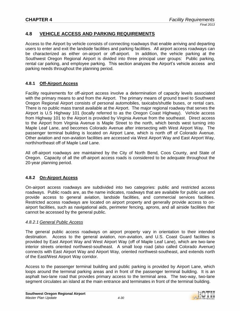
The required rental car demand fluctuates based upon passenger demand and time of year. Historical estimates indicate that approximately 12 percent of annual enplanements utilize rental cars. The historical rate is applied to the peak month average day enplanements to determine the ready/return lot parking space demand. Table 4-18 provides the projected rental car parking demand for the forecast of annual enplanements. The rental car ready/return lot contains a total of 30 spaces for rental cars. The rental car operation currently has sufficient capacity and should remain adequate throughout the planning period to provide customers with acceptable rental car service.
Actual
Description 2010 2015 2020 2025 2030
Annual Enplanements 22,585 24,701 28,405 32,661 37,560
Parking (Short / Long Term)
Parking spaces 173 86 99 114 131
Surplus / (Deficit) Parking Spaces - 87 74 59 42
Forecast
CHAPTER 4 Facility Requirements Final 2013
Southwest Oregon Regional Airport
Master Plan Update 4-33
Table 4-18 RENTAL CAR PARKING DEMAND PROJECTIONS
Source: Reynolds, Smith and Hills, Inc., 2012.
4.8.5 Employee Parking
Airport employees utilize the lower lot south of the terminal building, where five dedicated employee parking spots are located prior to the gate entry into the lower lot. Additional overflow parking for badged employees is also located to the east of the terminal building. Employees parking at the Airport include, but are not limited to: airport staff, TSA employees, rental car employees, and airline employees. The existing employee parking spots is considered adequate to accommodate employee parking demand throughout the planning period.
Actual
Description 2010 2015 2020 2025 2030
Annual Enplanements 22,585 24,701 28,405 32,661 37,560
Peak Month (August) 2,891 2,964 3,409 3,919 4,507
Average Day (31 Days) 93 96 110 126 145
Ready Rental Car Parking
Required No. Parking Spaces 19 20 21 22 24
No. Surplus / (Deficit) Parking Spaces 11 10 9 8 6
Forecast

CHAPTER 4 Facility Requirements Final 2013
Southwest Oregon Regional Airport
Master Plan Update 4-34
4.9 AVIATION SUPPORT FACILITIES
Support facilities at an airport encompass a broad set of functions that exist to ensure the airport is able to fill its primary role in a safe, and efficient manner. Support facilities at Southwest Oregon Regional Airport that were examined included:
Air Traffic Control Tower
Air Cargo Facilities
Fixed Base Operator
Aircraft Hangars
Aircraft Aprons
Aircraft Rescue and Fire Fighting Equipment and Facility
Airport Maintenance and Snow Removal Equipment Facility
Airport Fuel Storage
Deicing Facilities 4.9.1 Airport Traffic Control Tower
The Airport Traffic Control Tower (ATCT) facility was constructed in 2009, and is adequate to meet current and forecast operations. No changes are expected to occur with the surrounding airspace and, unless a significant change to airfield geometry occurs, the ATCT facility meets current FAA standards. 4.9.2 Air Cargo Facilities
Air cargo facilities are facilities dedicated to providing air mail and air freight/air express. FedEx is currently the only air cargo operator leasing building space, which is located behind the former passenger terminal building adjacent to the ARFF building. The Airport has minimal air cargo operations with only the 1,700-square yard tie-down area used for the FedEx hard stand. As discussed previously, reserving this area on the apron for air cargo operations was included in the aircraft parking apron requirements. Although it is recommended to maintain the hardstand area on the main apron for air cargo operations, no significant change from present day conditions is expected within the planning period. 4.9.3 Fixed Base Operators
The Airport has two Fixed Base Operators (FBOs), Ocean Air Aviation and Coos Aviation, which supply fuel, maintenance, aircraft storage, and other support services for the operators of general aviation aircraft. The 20-year forecasted demand anticipates growth to be within the existing business’ ability to provide services. 4.9.4 Hangars
The quantity of general aviation hangar space required at an airport depends on the total number of based aircraft, but also the local weather conditions, aircraft fleet mix, airport security, and user preference. Operators of single-engine aircraft and light twins are likely to opt for T-hangars or

CHAPTER 4 Facility Requirements Final 2013
Southwest Oregon Regional Airport
Master Plan Update 4-35
small box hangars, while general aviation business operations typically utilize corporate and conventional hangars. Due to the coastal location of the Airport, all 51 based aircraft owners prefer hangars to outdoor tie-down space. As such, all based aircraft are currently stored in hangars. There are nine hangar buildings at the Airport, three of which are owned by the Coos County Airport District, two are owned by the FBOs, and four are privately owned. These hangars consist of the 68,800-square foot clear-span hangar (main hangar), one small 1,900-square foot box hangar, and one 14-unit T-hangar building, of which all are leased to maximum capacity as reported by Airport Staff. The Airport leases half of the main hangar to Ocean Air Aviation, while the other half is leased to individual based aircraft tenants. Airport records also indicate there is a total of four aircraft owners on the T-hangar wait list. Analysis conducted to determine the amount of total hangar space and type of hangar facilities required for the planning period assumed that additional hangar demand during the planning period is likely to come from three sources: pent-up demand among owners, the FBOs desire for additional leasable space, and demand generated by owners moving up to larger aircraft. Based aircraft that cannot be accommodated in T-hangars or box/corporate hangars are stored in the main hangar. Demand for large conventional hangars would typically be driven by an aviation-oriented business or a corporate flight department. The 2002 Airport Master Plan discussed the potential replacement of the 68,800-square foot main hangar. The main hangar was built in 1941, constructed of wood, and is in close proximity to the fuel farm. Currently, there is no sprinkler system or other fire suppression system installed inside the main hangar, which does not meet the Oregon Fire Code for aircraft-related occupancies. The main hangar’s doors do not close and approximately 38 percent of the total square footage is comprised of circulation and unusable space, making a significant portion of the hangar nonfunctional for its intended purpose to store aircraft. As mentioned previously, half of the main hangar is leased to Ocean Air Aviation. Interviews with Ocean Air indicate that overnight storage during the peak summer months typically reaches maximum capacity inside the main hangar. Peak demand was included for the analysis. Chapter 3, Aviation Demand Forecasts, concluded that 11 new based aircraft are anticipated by 2030. Further, using planning standards established and accepted by the Airport in the 2002 Master Plan Update and 2004 Airport Layout Plan Revision, required square footage allocated by aircraft type was 1,100 square feet for single engine aircraft, and 2,000 square feet for multi-engine, turboprop, helicopter, and business jet aircraft. Two scenarios were developed to analyze the demand for additional hangars, including large conventional hangars, during the 20-year planning period. In Table 4-19, Scenario One shows the existing and forecast demand for hangar storage, assuming the main hangar will not be removed. As the main hangar has exceeded its functional life, Scenario Two, shown in Table 4-20, assumes the main hangar will be removed in the short-term and not replaced, to demonstrate the demand for hangar storage. Medium box and corporate hangars are typically used for small/medium business jets, large piston twins, helicopters, and turboprop aircraft. The analysis shown in Table 4-19 and Table 4-20 that existing box/corporate hangar space can accommodate demand throughout the planning period. Demand for small conventional hangars is largely price-driven and based on the aircraft owners’ plans for the hangar in addition to aircraft storage. T-hangars are a popular choice for small aircraft owners at many airports. T-hangars house single aircraft in a staggered, back-to-back configuration that maximizes the number of aircraft that can be hangared in a given area, while still giving each lessor private storage area and each aircraft

CHAPTER 4 Facility Requirements Final 2013
Southwest Oregon Regional Airport
Master Plan Update 4-36
direct access to the ramp. Both forecast facility requirements in Scenario One and Scenario Two indicate the market could support an additional multi-unit T-hangar that would accommodate current and future demand.
Table 4-19 HANGAR STORAGE REQUIREMENTS – SCENARIO ONE
Source: Reynolds, Smith and Hills, Inc., 2012.
Actual
Scenario One 2010 2015 2020 2025 2030
Total Based Aircraft 51 54 58 62 62
T-Hangar Square Footage (SF)
Required SF 19,800 19,800 19,800 19,800 19,800
Existing SF Used 15,400 15,400 15,400 15,400 15,400
Additional SF Needed Surplus / (Deficit) (4,400) (4,400) (4,400) (4,400) (4,400)
Box/Corporate Hangar SF
Required SF 32,200 32,200 32,200 32,200 32,200
Existing SF Used 42,500 42,500 42,500 42,500 42,500
Additional SF Needed Surplus / (Deficit) 10,300 10,300 10,300 10,300 10,300
Main Hangar SF
Total Hangar SF 68,800 68,800 68,800 68,800 68,800
Circulation/Unusable Storage SF 26,000 26,000 26,000 26,000 26,000
Leased/Reserved for Peak Overnight Storage SF 21,400 21,400 21,400 21,400 21,400
Required SF 22,000 26,200 31,500 36,800 36,800
Existing SF Used 21,400 21,400 21,400 21,400 21,400
Additional SF Needed Surplus / (Deficit) (600) (4,800) (10,100) (15,400) (15,400)
Reserved Maintenance Storage SF
Required SF (15% of Total Required SF) 11,243 11,881 12,686 13,492 13,492
Existing SF Used 10,300 10,300 10,300 10,300 10,300
Additional SF Needed Surplus / (Deficit) (943) (1,581) (2,386) (3,192) (3,192)
Projected

CHAPTER 4 Facility Requirements Final 2013
Southwest Oregon Regional Airport
Master Plan Update 4-37
Table 4-20 HANGAR STORAGE REQUIREMENTS – SCENARIO TWO
Source: Reynolds, Smith and Hills, Inc., 2012.
In both scenarios, new aircraft cannot be accommodated in hangars, and T-hanger demand for additional space remains constant from the base year throughout the 20 years. In Scenario One, hangar storage in the main hangar is currently deficient, and the demand for aircraft storage in the main hangar increases to 15,400 square feet deficit by the end of the planning period. Although the surplus in box/corporate hangars is used for maintenance storage, an estimated 15 percent of total hangar was used as the standard requirement for future years. As shown in both scenarios, the current shortage in maintenance storage is expected to increase throughout the 20-year planning period. In Scenario Two, without the main hangar, the current need grows to 36,800 square feet required to accommodate existing and new aircraft in hangars. Without the main hangar, multi-engine aircraft overnighting during the peak season may also trigger the need for additional box hangars. Further, 21,400 square feet used for peak overnight storage for transient aircraft would also need to be accommodated. Remaining box/corporate hangar space is currently utilized for maintenance storage; however, the existing capacity constraints indicate a deficit in maintenance storage space throughout the planning period. With the existing demand for aircraft hangar storage, the location and size of additional hangars will be analyzed in the Alternatives Analysis chapter. The Alternatives Analysis will also further examine the size and location of a potential replacement hangar(s) for the main hangar to accommodate future demand.
Actual
Scenario One 2010 2015 2020 2025 2030
Total Based Aircraft 51 54 58 62 62
T-Hangar Square Footage (SF)
Required SF 19,800 19,800 19,800 19,800 19,800
Existing SF Used 15,400 15,400 15,400 15,400 15,400
Additional SF Needed Surplus / (Deficit) (4,400) (4,400) (4,400) (4,400) (4,400)
Box/Corporate Hangar SF
Required SF 32,200 32,200 32,200 32,200 32,200
Existing SF Used 42,500 42,500 42,500 42,500 42,500
Additional SF Needed Surplus / (Deficit) 10,300 10,300 10,300 10,300 10,300
Main Hangar SF
Total Hangar SF 68,800 0 0 0 0
Circulation/Unusable Storage SF 26,000 0 0 0 0
Leased/Reserved for Peak Overnight Storage SF 21,400 (21,400) (21,400) (21,400) (21,400)
Required SF 22,000 26,200 31,500 36,800 36,800
Existing SF Used 21,400 0 0 0 0
Additional SF Needed Surplus / (Deficit) (600) (26,200) (31,500) (36,800) (36,800)
Reserved Maintenance Storage SF
Required SF (15% of Total Required SF) 11,243 11,881 12,686 13,492 13,492
Existing SF Used 10,300 10,300 10,300 10,300 10,300
Additional SF Needed Surplus / (Deficit) (943) (1,581) (2,386) (3,192) (3,192)
Projected

CHAPTER 4 Facility Requirements Final 2013
Southwest Oregon Regional Airport
Master Plan Update 4-38
4.9.5 General Aviation Aprons
The general aviation aprons at the Airport provide areas for aircraft parking, fueling, and tie-downs, as well as aircraft movement to and from parking and storage hangars. Demand for general aviation apron space is primarily driven by itinerant aircraft not desiring hangar storage. FAA Advisory Circular 150/5300-13, Appendix 5, provides a methodology by which apron requirements can be determined for general aviation facilities. Analysis conducted to determine parking requirements for itinerant aircraft calculated daily parking demand by focusing on the peak month of operations. FAA planning criteria recommends the amount of itinerant aircraft parking positions needed at one time be approximately 50 percent of the peak day itinerant operating aircraft. Currently, aircraft dwell time is a significant contributor to the Airport’s apron congestion. Increased dwell time occurs when aircraft remain parked on the ramp longer than 24 hours, instead of departing shortly after arriving passengers have been deplaned. At OTH, transient aircraft frequently stay parked more than 24 hours, and sometimes up to a week, occupying apron space that would otherwise be available for arriving traffic. Thus, a higher percentage than 50 percent of the peak day itinerant operating aircraft was used to determine required apron parking positions. In addition, this anlaysis also assumed that the peak month will increase in proportion to the year over year percent change in operations. Considering both the local and itinerant aircraft fleet mix, as previously adopted by the Airport in the 2004 Airport Layout Plan Revision, a planning standard of approximately 1,700 square yards of apron should be provided for each itinerant aircraft position (including helicopters), and approximately 580 square yards should be provided for each single engine aircraft tie-down position. Airport records indicate there are approximately 12 anchored tie-downs on the main ramp, with one reserved as the FedEx hard stand for cargo operations. On the remaining 22,070 square yards available for itinerant aircraft parking, approximately 13 jets could be parked on the main apron. Table 4-21 provides the aircraft parking apron required to accommodate forecasted demand during the 20-year planning period.

CHAPTER 4 Facility Requirements Final 2013
Southwest Oregon Regional Airport
Master Plan Update 4-39
Table 4-21 AIRCRAFT PARKING APRON REQUIREMENTS
Source: RS&H Analysis, 2012. (1)
Includes South GA / Itinerant Overflow Apron (2)
Includes 13 jet positions on main apron, and five small aircraft parking positions located on the South GA/Itinerant Overflow Aprons. The South GA/Itinerant Overflow Apron has three anchored and two non-anchored tie-down positions.
Cumulatively, the total local and itinerant apron need is over 52,000 square yards over the 20-year planning period. The local apron requirement throughout the planning period is approximately 8,080 square yards to accommodate the existing 11 anchored tie-down positions for based aircraft, and the FedEx hard stand. However, remaining space on the main apron available for itinerant use combined with the South General Aviation apron area available for overflow parking, currently cannot accmodate demand for itinerant aircraft parking. The existing apron shortage of 3,682 square yards will increase to 14,607 square yards by 2030, equating to at least 12 aircraft parking positions. During consultation with the Master Plan Advisory Committee (MPAC), it was indicated that on an average annual basis, there is generally sufficient parking apron available to meet existing demand; however, peak demand can occur more frequently even outside of the peak season. Further, the MPAC reports that tie-down space is especially limited for smaller general aviation aircraft during the peak season, as several business jets are tightly parked over existing tie-down positions. The MPAC also expressed that there can be nearly 30 jets on the apron, and at times are required to turn away overnight transient users when the main apron is at full capacity. Development alternatives to accommodate existing and forecasted peak demand for apron space will be examined in the next chapter.
Apron Requirements 2010 2015 2020 2025 2030
Total Main Apron (SY) 30,150 30,150 30,150 30,150 30,150
Total South GA / Itinerant Overflow Apron (SY) 7,939 7,939 7,939 7,939 7,939
Local Aircraft Parking
Local Tie-Down Requirement (SY) 6,380 6,380 6,380 6,380 6,380
FedEx Hard Stand Requirement (SY) 1,700 1,700 1,700 1,700 1,700
Total Local Apron Requirement (SY) 8,080 8,080 8,080 8,080 8,080
Available Tie-Down Positions 12 12 12 12 12
Local Tie-Down Positions Requirement 9 9 9 9 10
Total Local Tie-Down Positions Surplus / (Deficit) 3 3 3 3 2
Itinerant Aircraft Parking
Itinerant Peak Day Operating Aircraft 30 33 35 37 40
Itinerant Apron Available on Main Apron (SY) 22,070 22,070 22,070 22,070 22,070
Itinerant Apron Requirement (SY) 33,691 36,761 38,376 41,642 44,616
Total Itinerant Apron Requirement (SY) Surplus / (Deficit)(1) (3,682) (6,752) (8,367) (11,633) (14,607)
Available Itinerant Aircraft Parking Positions (2) 18 18 18 18 18
Itinerant Aircraft Parking Positions Requirement 23 25 26 28 30
Total Itinerant Aircraft Positions Surplus / (Deficit) (5) (7) (8) (10) (12)

CHAPTER 4 Facility Requirements Final 2013
Southwest Oregon Regional Airport
Master Plan Update 4-40
4.9.6 Airport Fuel Storage
Fuel storage requirements at the Airport depend on the level of aircraft traffic, fleet mix, and fuel delivery schedules. Changes in aircraft fleet mix, for example, air carrier turboprops being replaced by jets, or piston twins being replaced by turboprops, will likely increase demand for Jet-A. Table 4-22 outlines fuel storage requirements for the 20-year planning period. The current total storage capacity for 100LL avgas is 9,500 gallons and 22,000 gallons for Jet-A fuel. Based upon average bulk fuel delivery estimates reported by the FBOs during the peak months, the five-day peak supply requirement for 100LL is approximately 981 gallons, and is forecast to decrease to 311 gallons by 2030. The five-day peak supply requirement for Jet-A is currently approximately 22,350 gallons, and is forecast to increase to 76,038 gallons by 2030. Increases (or decreases) in airline service will also affect future Jet-A storage needs. Appropriate storage for 100LL avgas appears adequate throughout the forecast period, while a deficit in Jet-A storage capacity increases to a 54,038 gallon need by 2030. This does not include any fuel storage capacities contained within fuel trucks. The growing need for Jet-A fuel storage capacity is a result of increasing peak month general aviation operations and commercial jet operations, as turboprops are replaced with regional jets during the planning period. As shown below, existing Jet-A fuel storage capacity is not adequate to accommodate peak season demand.
Table 4-22 FUEL FACILITY REQUIREMENTS
Source: Reynolds, Smith and Hills, Inc., 2012.
As required by the Environmental Protection Agency (EPA), Title 40 of the Code of Federal Regulations (CFR) Part 112, a Spill Prevention Control, and Countermeasure (SPCC) Plan is required for aboveground oil storage capacity exceeding 1,320 gallons. 4.9.7 Aircraft Rescue and Fire Fighting Equipment and Facility
Airports that serve air carrier flights are required to provide Aircraft Rescue and Firefighting (ARFF) facilities and equipment. ARFF equipment requirements for FAR Part 139 airports are determined by an index ranking based on aircraft size, number of emergency vehicles, and number of scheduled daily aircraft departures. As published by the FAA, Southwest Oregon Regional Airport
2010 2015 2020 2025 2030
Peak Month Average Day (PMAD) Operations 58 56 58 61 63
100 LL AvGas
PMAD Fuel Requirement 196 161 129 131 62
5 Day Fuel Need (gallons) 981 806 646 653 311
Available Storage (gallons) 9,500 9,500 9,500 9,500 9,500
Additional Storage Needed Surplus / (Deficit) 8,519 8,694 8,854 8,847 9,189
Jet-A
PMAD Fuel Requirement 4,470 6,354 9,187 12,032 15,208
5 Day Fuel Need (gallons) 22,350 31,769 45,934 60,159 76,038
Available Storage (gallons) 22,000 22,000 22,000 22,000 22,000
Additional Storage Needed Surplus / (Deficit) (350) (9,769) (23,934) (38,159) (54,038)

CHAPTER 4 Facility Requirements Final 2013
Southwest Oregon Regional Airport
Master Plan Update 4-41
is FAR Part 139 Class I, with an ARFF Index A, and on request by contacting the Airport Manager, the Airport can meet Index B requirements. The existing 3,786 square foot ARFF building was built in 1960, and is in poor condition. The ARFF building is centrally located immediately south of the main hangar, on the southwest side of the main apron. Currently, the ARFF building houses two fire rescue vehicles, and essential equipment. As the building has exceeded its useful life and service condition, the ARFF building should be replaced with one that has the ability to accommodate two trucks, fire station boats, and ARFF personnel and equipment based on design standards specified in FAA AC 150/5210-15A, Aircraft Rescue and Firefighting Station Building Design. The primary ARFF vehicle is a 2002 all-wheel drive KME truck, with a capacity of 1,500 gallons of water and 250 gallons of foam. This vehicle meets FAA Index B requirements, which include the capability of holding 1,500 gallons of water and 200 gallons of foam. In addition, the older 1984 Ameritek ARFF truck will require replacement during the planning period based upon FAA AC 160/5220-10E, Guide Specification for Aircraft Rescue and Fire Fighting Vehicles. 4.9.8 Airport Maintenance Equipment Facility
The demand for airport maintenance facilities is directly related to the amount of pavement, lighting equipment, terminal building size, and overall grounds maintenance airport staff is required to maintain. Since the airport maintenance building was constructed in 1941, the condition of the building is deteriorating and may need to be replaced at some point during the planning period. It can also be assumed that as the airfield and/or facilities are enlarged, the maintenance facilities may also need to be expanded and perhaps relocated. Although no large-scale infrastructure additions are anticipated, the maintenance facility at Southwest Oregon Regional Airport has exceeded its useful life and is considered inadequate for the 20-year planning period. 4.9.9 Deicing and Snow Removal
Aircraft deicing facilities are recommended at airports where icing conditions are expected. With the area’s relatively mild winters, deicing activity at Southwest Oregon Regional Airport is rare, although the Airport has deicing capabilities. When deicing is necessary, commercial aircraft are deiced by United/SkyWest Airlines. The Airport’s snow removal equipment includes a 2009 TYM 903 4-wheel drive tractor with a half-yard bucket, and a 1993 Ford 660 2x4 tractor with seven-foot roll broom attachment, and is considered adequate to accommodate future snow removal activities. Runoff from the deicing process has the potential to cause environmental degradation in nearby waterways. Consideration should be given to creating a mitigation plan to ensure minimal deicing fluid reaches waterways.

CHAPTER 4 Facility Requirements Final 2013
Southwest Oregon Regional Airport
Master Plan Update 4-42
4.10 ENVIRONMENTAL CONDITIONS
Existing environmental categories identified as a potential concern to the Airport’s development include coastal resources, fish, wildlife, and plants, and wetlands. Due to the Airport’s location adjacent to Coos Bay, there are sensitive environmental issues to consider for any potential subsequent NEPA process. A few examples of such scenarios are as follows:
Future development that may conflict with policies and planning goals of the Oregon Coastal Zone Management Program, which enforces the Coastal Zone Management Act (CZMA). Agency coordination with the Oregon Department of Land Conservation and Development would be recommended for any projects affecting the Coos Bay.
Land expansion into Coos Bay may affect the habitats for groundfish, coastal pelagic species, and Pacific salmon, which are protected under the federal Fishery Management Plan (FMP) in Oregon. Coordination with the U.S. Fish and Wildlife Service (USFWS) would be necessary to determine the potential impacts to these habitats.
Construction on- or off-airport property may disturb “jurisdictional” or “non-jurisdictional” wetlands defined by the U.S Army Corps of Engineers (USACE) or the Oregon Department of State Lands (DSL). A wetland delineation report (WDR) conducted by a wetland specialist would define the extent and impact of such resources and possible mitigation measures if needed. Agency coordination with USACE and DSL is recommended prior to any design or construction efforts given the presence of wetlands surrounding the Airport.
Most of the projects listed in Table 4-23 would likely require categorical exclusion (CatEx) documentation under NEPA. However, given the sensitive nature of the environmental impact categories discussed above, potential development may result in an Environmental Assessment (EA). The Airport should coordinate with the local FAA ADO on the appropriate course of action during the initial design phase for the project. An analysis of each potential development project and its effect on each environmental impact category will be discussed in Chapter 5.

CHAPTER 4 Facility Requirements Final 2013
Southwest Oregon Regional Airport
Master Plan Update 4-43
4.11 SUMMARY OF MAJOR AIRPORT FACILITY NEEDS
The airport facilities requirements needed to adequately accommodate the forecast activity, address FAA design standards, and meet the strategic goals for the Airport have been addressed within this chapter. Certain facility requirements identified in this chapter will require further analysis to determine the optimum layout and potential, which will be evaluated in Chapter 5, Alternatives Analysis. The summary of major airport facility needs are listed below in Table 4-23.
Table 4-23 SUMMARY OF MAJOR AIRPORT FACILITY NEEDS
Source: RS&H, 2012.
Item Identified Need
Runway Safety Area (RSA) Runway 22 RSA does not meet FAA design standards for C-III
Object Free Area (OFA) Runway 22 OFA does not meet FAA design standards for C-III
Object Free Area (OFA) Runway 31 OFA does not meet FAA design standards for C-III
Object Free Area (OFA)A portion of the East Perimeter Road is located inside the Runway
31 OFARunway Protection Zones
(RPZs)
Acquire in fee simple or easement property within the Runway 04,
22, 13, 31 RPZs not controlled by the Airport
Taxiway BIncrease Taxiway B width by eight feet to meet ADG-III 50-foot width
design standard
Taxiway C Runway 13 and Taxiway C intersection FAA designated "Hotspot"
Taxiway A1, and A2 Taxiways do not meet Engineering Brief 75 recommended guidance
Taxiway ShouldersAdd 20-foot wide stabilized or paved shoulders to Taxiways A, B, C,
D, F, and G to meet ADG-III design standardPavement Strength and
ConditionImplement Pavement Maintenance Plan for all airfield pavement
Visual Aids Install REILs to Runway 22
Visual Aids Upgrade Runway 04 and Runway 13 VASIs to PAPIs
Visual Aids Upgrade Taxiway K edge reflectors to MITLs
T-Hangars An additional 4,400 SF are needed
Conventional Hangars An additional 15,400 SF are needed
Aircraft Apron An additional 2,911 SY are needed
ARFF Building Replace ARFF building due useful life and insufficient space
ARFF Equipment Replace the 1984 Ameritek ARFF truck
Airport Maintance Building Replace building due to useful life and insufficient space
Vehicle Access Improve airport entrance vehicle wayfinding and signage