Embed Size (px)
DESCRIPTION
CHAPTER 4 Aircraft Welding JEPPESEN - Airframethis chapter is about aircraft welding and it's techniquesPublished in 2001
Citation preview
AIRCRAFT WELDING
INTRODUCTION
Metallic aircraft structures are composed of many individual pieces that must be securely fastened together to form a complete structural unit. Fusion welding, non-fusion welding, hardware fasteners, and adhesives are the principal methods used in the construction and repair of metal aircraft joints. This chapter describes the equip-ment and basic procedures needed to join metals using fusion and non-fusion welding techniques, and the meth-ods used to repair welded aircraft structures. Since welding has become so highly specialized, the FAA no longer requires a person to perform welding to a high skill level to become a certified aircraft technician. If you have an interest in specializing in this area, you will need to pursue advanced training. One source of additional infor-mation on advanced aircraft welding techniques is the book Welding Guidelines, which is available from Jeppesen.
WELDING PROCESSES
Aircraft maintenance technicians are no longer required to be highly proficient at performing weld repairs or fabricating welded parts for aircraft. In fact, in most cases the technician should delegate the responsibility for welding aircraft parts to FAA-certified repair stations that specialize in welding processes. However, aircraft technicians are expected to have sufficient knowledge to enable them to identify defective welds to determine the airworthiness of an aircraft.
The two most prominent methods of welding air-craft structures and components are fusion and non-fusion. Fusion welding is the blending of compatible molten metals into one common part or joint. Fusing of metals is accomplished by producing sufficient heat for the metals to melt, flow together and mix. The heat is then removed to allow the fused joint to solidify. Non-fusion welding is the joining of metals by adhesion of one metal to another. The most prominent non-fusion welding processes used on aircraft are brazing and soldering, which are covered in detail later in this section.
FUSION WELDING PROCESSES The three principal methods of fusion welding are gas, electric arc, and electrical resistance. Fusion welding has, for some time, been the method of choice for constructing the structural framework of aircraft. It still is used extensively on the framework of many modern small airplanes, particularly in aer-obatic, agricultural and homebuilt machines, but is used to some degree in virtually all aircraft. Fusion welding results in superior strength joints because the metal parts are melted together into a single solid object. Since fusion-welded joints are used extensively in high-stress applications, their failure is likely to have catastrophic consequences. To fully appreciate the level of detail that must be exercised when inspecting welded components, you must be aware of the characteristics that define a quality fusion-welded joint.
GENERAL EVALUATION OF WELDS A good weld is uniform in width, with even ripples that taper off smoothly into the base metal. It shows
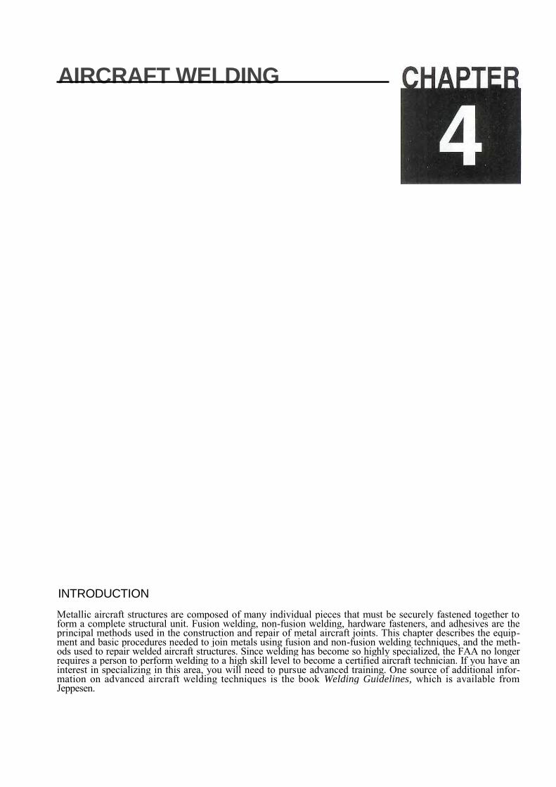
good penetration, or depth of fusion. In fact, pene-tration is the most important characteristic of a good weld. To obtain the proper amount of penetration and proper weld dimensions, a welder must use the correct type and size of filler rod and appropriate welding technique for the thickness and type of the material to be joined. A good weld also is well rein-
Figure 4-1. Proper penetration is the single most important
characteristic of a good weld.
forced. This means there is enough filler material across the joint to provide sufficient strength, as shown in Figure 4-1. A good weld is also free of excessive oxidation.
Poor welds display certain characteristics. A cold weld has irregular edges and considerable variation in depth of penetration, while a weld from exces-sive heat shows pitting along its edges and long, pointed ripples. If cracks appear adjacent to a weld, it means a part may have cooled too quickly after being welded. If a welded joint displays any of these defects, all of the old weld must be removed and the joint rewelded. In other cases, the part may need additional reinforcement repairs, or it may be nec-essary or more economical to scrap and replace the part.
OXIDATION Oxidation is a primary concern to a welder. Metal oxides are formed in the welding zone of most
Aircraft Welding 4-3
metallic alloys when sufficient heat is applied. Oxygen chemically reacts with the heated surface of the metal and forms metal oxides such as iron oxide (rust) or aluminum oxide. When excessive oxide is present, it often results in porous pockets, causing a weak joint. Limiting the effects of oxidation is criti-cal to maintaining strong weld joints.
Each type of fusion welding controls the formation of oxides differently. The gas welding processes generate carbon dioxide (CO2), which shields the welding zone from oxygen. CO2 is a natural by-product of oxygen and acetylene combustion. In welding processes that use an electric arc for heat, other methods of shielding the weld are used, including coating electrodes with flux, or using gases to flood the area around the arc to shield the weld from oxygen.
OXYACETYLENE WELDING Oxyacetylene welding, often referred to as gas weld-ing, gets its name from the two gases, oxygen and acetylene, that are used to produce a flame. Acetylene is the fuel for the flame and oxygen sup-ports combustion and makes the flame hotter. The combination of these two gases results in sufficient heat to produce molten metal. The temperature of the oxyacetylene flame ranges from 5,600 to 6,300 F.
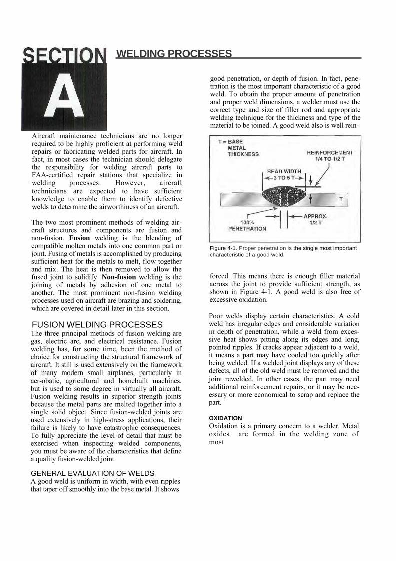
Most aircraft gas welding is done on thin-gauge steel that ranges from 16- to 20-gauge, or about .027- to .050-inch thick. Welding thicker metals requires larger equipment; however, welding techniques remain much the same. Aircraft structures of steel tubing are usually fabricated by welding the tubes together into a strong, lightweight structure. [Figure 4-2]
Section C of this chapter introduces the procedures for proper handling, setup and safe use of oxyacety-lene equipment. It also explains the fundamentals of oxyacetylene-torch cutting. Although you are not required to become proficient in performing welds, a background in basic oxyacetylene welding skills may prove useful in the maintenance of tools and shop equipment.
ELECTRIC ARC WELDING Electric arc welding includes shielded metal arc welding, gas metal arc welding, and tungsten inert gas [TIG) arc welding. Although TIG welding is the method that is predominantly used in aircraft fabri-cation and repair, a technician is also required to understand the other methods.
When electricity has sufficient voltage to arc across the space between an electrode to an area of differ-ent electrical potential, heat is produced from the movement of electrons. The amount of heat is pre-dominantly determined by the amount of current (amperage) flowing across the gap. For all types of arc welding, a transformer/rectifier (TR) unit is used to produce and control electrical power. An addi-tional feature is that the TR unit has the capability of changing the polarity of electricity that flows out of its terminals.
Electric arc welding produces a blinding light, with infrared and ultraviolet rays, which can burn both skin and eyes. Before being exposed to a welding arc, you must wear an arc-welding helmet, gloves and proper clothing. Anyone observing electric arc welding also needs appropriate protective gear. Heavy clothing or leather aprons should be worn to cover as much skin as practical. The use of light-weight fabric materials does not provide adequate protection to prevent burns to the skin.
SHIELDED METAL ARC WELDING Shielded metal arc welding (SMAW), or stick weld-ing, is the most common type of arc welding. You may find stick welding useful for fabricating tools and shop equipment, but it is not generally used for the fabrication or repair of aircraft.
In SMAW welding, a metal wire rod, which is com-posed of approximately the same chemical compo-sition as the metal to be welded, is clamped in an electrode holder. This holder, in turn, is connected to one terminal of the TR power supply by a heavy gauge electrical cable. The metal to be welded is attached to the other terminal of the power supply through another electrical cable usually equipped with a spring clamp. The technician strikes an arc
Figure 4-2. Oxyacetylene welding was once used almost exclusively in the fabrication of welded-tube aircraft fuse-lage structures.
4-4 Aircraft Welding
between the wire rod and the metal, which pro-duces heat capable of exceeding 10,000 F. This intense heat melts both the metal and the rod.
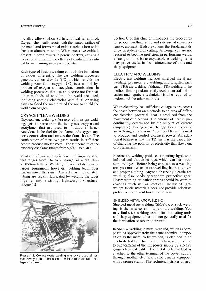
As previously mentioned, the welding process accel-erates oxidation, a harmful chemical reaction between the metal and the oxygen in the air. It is a major concern, and must be controlled to obtain a quality weld. To accomplish this, the arc-welding rod is coated with flux, which protects the welding zone from the air as it burns. As the flux burns from the rod, it releases an inert gas that shields the molten metal. When the weld is complete, an airtight slag covers the weld bead as it cools. This slag must be chipped off to examine the weld. [Figure 4-3]
Figure 4-3. Shielded metal arc welding normally is used for welding heavy gauge steel. It seldom is used for aircraft construction or repair.
GAS METAL ARC WELDING Gas metal arc welding (GMAW), formerly called Metal Inert Gas (MIG) welding, is used primarily in large volume production work. An advantage of GMAW over stick welding is that no slag is deposited on the weld bead. An uncoated filler wire acts as the electrode. It is connected to one terminal on the power supply, and fed into the torch. An inert gas such as argon, helium or carbon dioxide flows out around the wire to protect the weld zone from oxygen. The metal to be welded is connected to the other terminal of the power supply. When power is supplied to the electrode, and it is brought into contact with the work, it produces an arc, which melts the metal and the filler wire.
TUNGSTEN INERT GAS WELDING Tungsten inert gas welding (TIG) is the form of elec-tric arc welding that is used most in aircraft mainte-nance. It also is known as gas tungsten arc welding
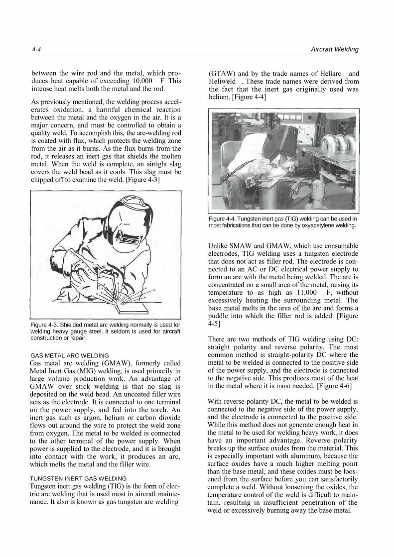
(GTAW) and by the trade names of Heliarc and Heliweld . These trade names were derived from the fact that the inert gas originally used was helium. [Figure 4-4]
Figure 4-4. Tungsten inert gas (TIG) welding can be used in most fabrications that can be done by oxyacetylene welding.
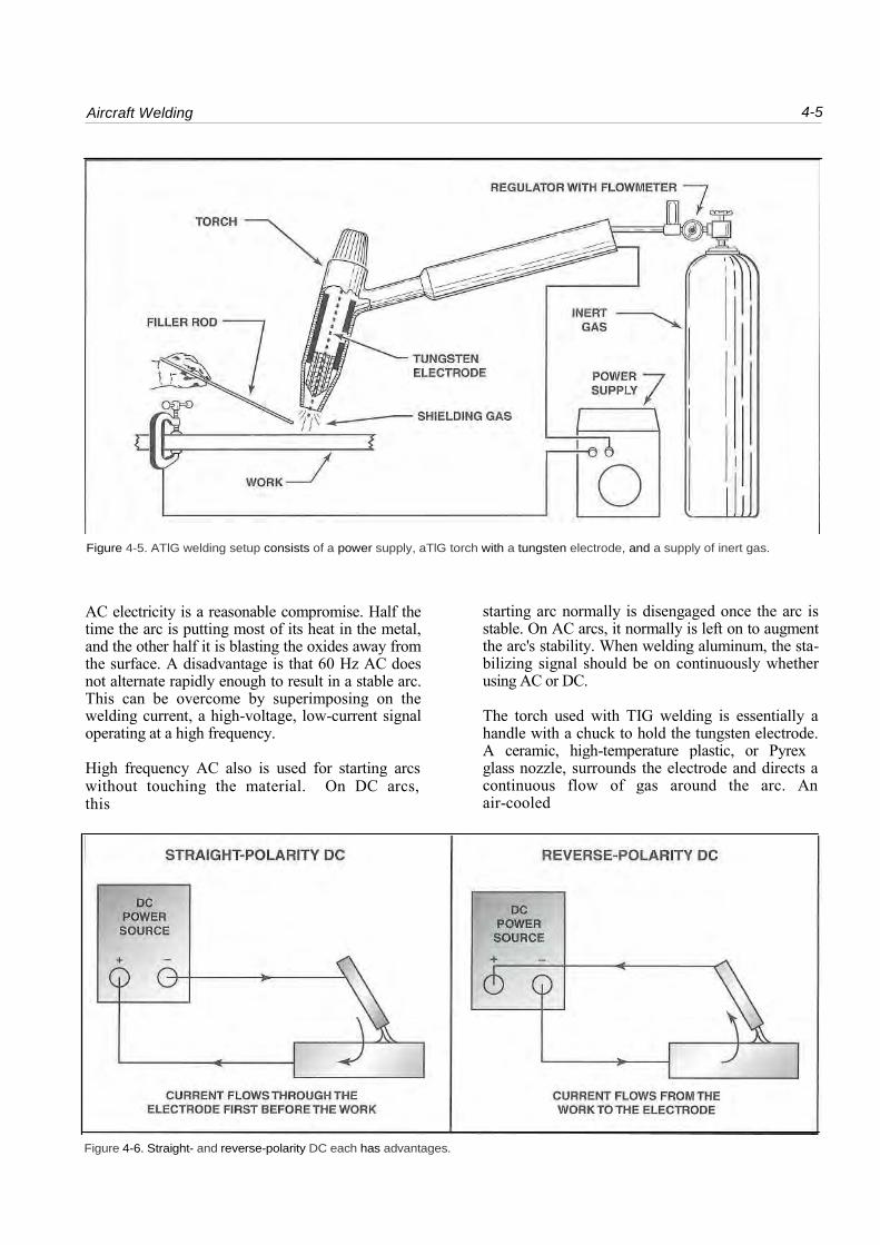
Unlike SMAW and GMAW, which use consumable electrodes, TIG welding uses a tungsten electrode that does not act as filler rod. The electrode is con-nected to an AC or DC electrical power supply to form an arc with the metal being welded. The arc is concentrated on a small area of the metal, raising its temperature to as high as 11,000 F, without excessively heating the surrounding metal. The base metal melts in the area of the arc and forms a puddle into which the filler rod is added. [Figure 4-5]
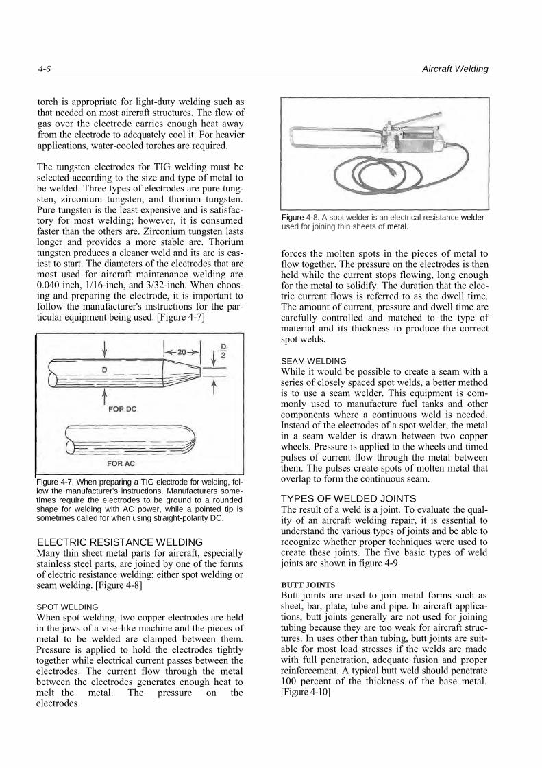
There are two methods of TIG welding using DC: straight polarity and reverse polarity. The most common method is straight-polarity DC where the metal to be welded is connected to the positive side of the power supply, and the electrode is connected to the negative side. This produces most of the heat in the metal where it is most needed. [Figure 4-6]
With reverse-polarity DC, the metal to be welded is connected to the negative side of the power supply, and the electrode is connected to the positive side. While this method does not generate enough heat in the metal to be used for welding heavy work, it does have an important advantage. Reverse polarity breaks up the surface oxides from the material. This is especially important with aluminum, because the surface oxides have a much higher melting point than the base metal, and these oxides must be loos-ened from the surface before you can satisfactorily complete a weld. Without loosening the oxides, the temperature control of the weld is difficult to main-tain, resulting in insufficient penetration of the weld or excessively burning away the base metal.
Aircraft Welding 4-5
Figure 4-5. ATlG welding setup consists of a power supply, aTlG torch with a tungsten electrode, and a supply of inert gas.
AC electricity is a reasonable compromise. Half the time the arc is putting most of its heat in the metal, and the other half it is blasting the oxides away from the surface. A disadvantage is that 60 Hz AC does not alternate rapidly enough to result in a stable arc. This can be overcome by superimposing on the welding current, a high-voltage, low-current signal operating at a high frequency.
High frequency AC also is used for starting arcs without touching the material. On DC arcs, this
starting arc normally is disengaged once the arc is stable. On AC arcs, it normally is left on to augment the arc's stability. When welding aluminum, the sta-bilizing signal should be on continuously whether using AC or DC.
The torch used with TIG welding is essentially a handle with a chuck to hold the tungsten electrode. A ceramic, high-temperature plastic, or Pyrex glass nozzle, surrounds the electrode and directs a continuous flow of gas around the arc. An air-cooled
Figure 4-6. Straight- and reverse-polarity DC each has advantages.
4-6 Aircraft Welding
torch is appropriate for light-duty welding such as that needed on most aircraft structures. The flow of gas over the electrode carries enough heat away from the electrode to adequately cool it. For heavier applications, water-cooled torches are required.
The tungsten electrodes for TIG welding must be selected according to the size and type of metal to be welded. Three types of electrodes are pure tung-sten, zirconium tungsten, and thorium tungsten. Pure tungsten is the least expensive and is satisfac-tory for most welding; however, it is consumed faster than the others are. Zirconium tungsten lasts longer and provides a more stable arc. Thorium tungsten produces a cleaner weld and its arc is eas-iest to start. The diameters of the electrodes that are most used for aircraft maintenance welding are 0.040 inch, 1/16-inch, and 3/32-inch. When choos-ing and preparing the electrode, it is important to follow the manufacturer's instructions for the par-ticular equipment being used. [Figure 4-7]
Figure 4-7. When preparing a TIG electrode for welding, fol-low the manufacturer's instructions. Manufacturers some-times require the electrodes to be ground to a rounded shape for welding with AC power, while a pointed tip is sometimes called for when using straight-polarity DC.
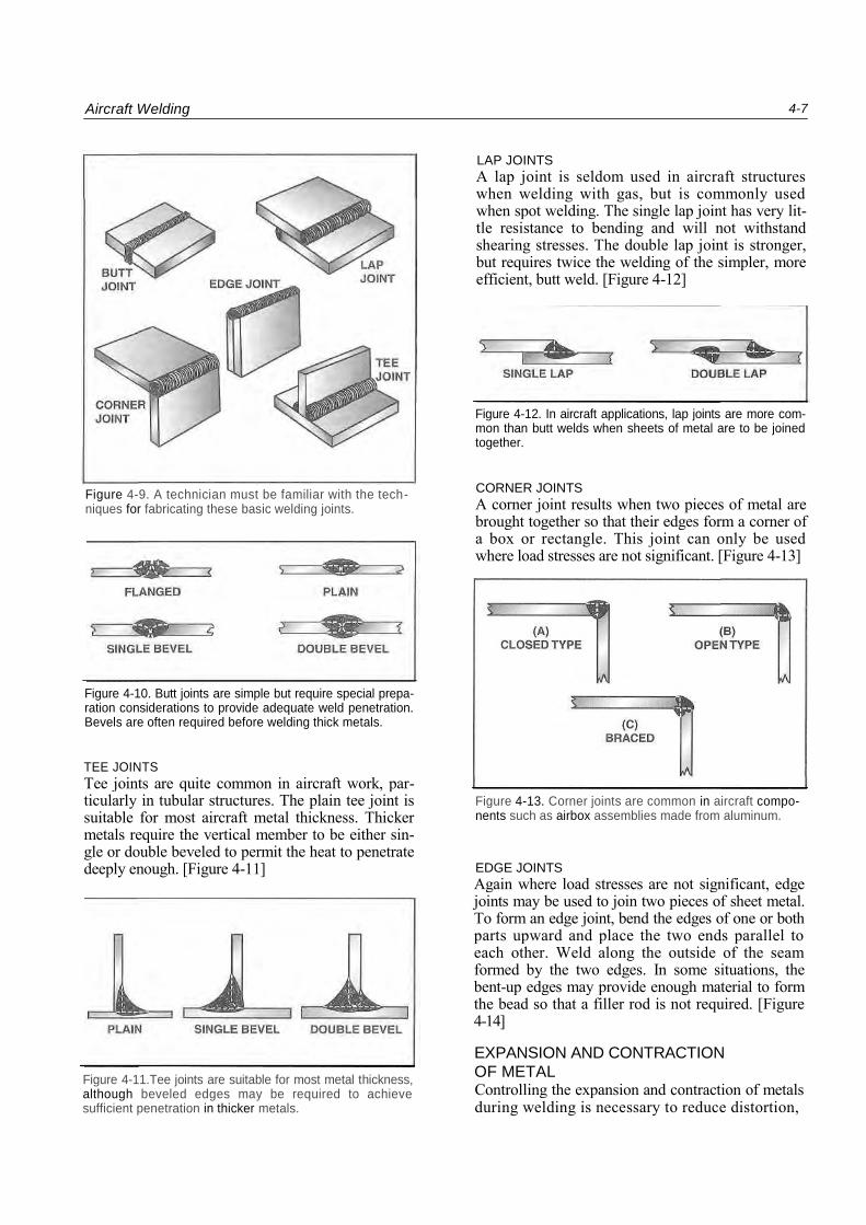
ELECTRIC RESISTANCE WELDING Many thin sheet metal parts for aircraft, especially stainless steel parts, are joined by one of the forms of electric resistance welding; either spot welding or seam welding. [Figure 4-8]
SPOT WELDING When spot welding, two copper electrodes are held in the jaws of a vise-like machine and the pieces of metal to be welded are clamped between them. Pressure is applied to hold the electrodes tightly together while electrical current passes between the electrodes. The current flow through the metal between the electrodes generates enough heat to melt the metal. The pressure on the electrodes
Figure 4-8. A spot welder is an electrical resistance welder used for joining thin sheets of metal.
forces the molten spots in the pieces of metal to flow together. The pressure on the electrodes is then held while the current stops flowing, long enough for the metal to solidify. The duration that the elec-tric current flows is referred to as the dwell time. The amount of current, pressure and dwell time are carefully controlled and matched to the type of material and its thickness to produce the correct spot welds.
SEAM WELDING While it would be possible to create a seam with a series of closely spaced spot welds, a better method is to use a seam welder. This equipment is com-monly used to manufacture fuel tanks and other components where a continuous weld is needed. Instead of the electrodes of a spot welder, the metal in a seam welder is drawn between two copper wheels. Pressure is applied to the wheels and timed pulses of current flow through the metal between them. The pulses create spots of molten metal that overlap to form the continuous seam.
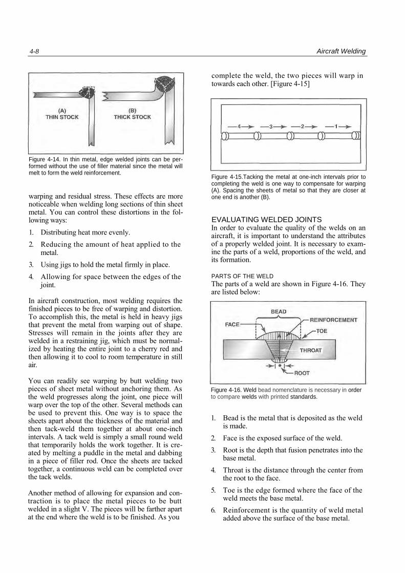
TYPES OF WELDED JOINTS The result of a weld is a joint. To evaluate the qual-ity of an aircraft welding repair, it is essential to understand the various types of joints and be able to recognize whether proper techniques were used to create these joints. The five basic types of weld joints are shown in figure 4-9.
BUTT JOINTS Butt joints are used to join metal forms such as sheet, bar, plate, tube and pipe. In aircraft applica-tions, butt joints generally are not used for joining tubing because they are too weak for aircraft struc-tures. In uses other than tubing, butt joints are suit-able for most load stresses if the welds are made with full penetration, adequate fusion and proper reinforcement. A typical butt weld should penetrate 100 percent of the thickness of the base metal. [Figure 4-10]
Aircraft Welding 4-7
Figure 4-9. A technician must be familiar with the tech-niques for fabricating these basic welding joints.
Figure 4-10. Butt joints are simple but require special prepa-ration considerations to provide adequate weld penetration. Bevels are often required before welding thick metals.
TEE JOINTS Tee joints are quite common in aircraft work, par-ticularly in tubular structures. The plain tee joint is suitable for most aircraft metal thickness. Thicker metals require the vertical member to be either sin-gle or double beveled to permit the heat to penetrate deeply enough. [Figure 4-11]
Figure 4-11.Tee joints are suitable for most metal thickness, although beveled edges may be required to achieve sufficient penetration in thicker metals.
LAP JOINTS A lap joint is seldom used in aircraft structures when welding with gas, but is commonly used when spot welding. The single lap joint has very lit-tle resistance to bending and will not withstand shearing stresses. The double lap joint is stronger, but requires twice the welding of the simpler, more efficient, butt weld. [Figure 4-12]
Figure 4-12. In aircraft applications, lap joints are more com-mon than butt welds when sheets of metal are to be joined together.
CORNER JOINTS A corner joint results when two pieces of metal are brought together so that their edges form a corner of a box or rectangle. This joint can only be used where load stresses are not significant. [Figure 4-13]
Figure 4-13. Corner joints are common in aircraft compo-nents such as airbox assemblies made from aluminum.
EDGE JOINTS Again where load stresses are not significant, edge joints may be used to join two pieces of sheet metal. To form an edge joint, bend the edges of one or both parts upward and place the two ends parallel to each other. Weld along the outside of the seam formed by the two edges. In some situations, the bent-up edges may provide enough material to form the bead so that a filler rod is not required. [Figure 4-14]
EXPANSION AND CONTRACTION
OF METAL Controlling the expansion and contraction of metals during welding is necessary to reduce distortion,
4-8 Aircraft Welding
Figure 4-14. In thin metal, edge welded joints can be per-formed without the use of filler material since the metal will melt to form the weld reinforcement.
warping and residual stress. These effects are more noticeable when welding long sections of thin sheet metal. You can control these distortions in the fol-lowing ways: 1. Distributing heat more evenly. 2. Reducing the amount of heat applied to the
metal. 3. Using jigs to hold the metal firmly in place. 4. Allowing for space between the edges of the
joint.
In aircraft construction, most welding requires the finished pieces to be free of warping and distortion. To accomplish this, the metal is held in heavy jigs that prevent the metal from warping out of shape. Stresses will remain in the joints after they are welded in a restraining jig, which must be normal-ized by heating the entire joint to a cherry red and then allowing it to cool to room temperature in still air.
You can readily see warping by butt welding two pieces of sheet metal without anchoring them. As the weld progresses along the joint, one piece will warp over the top of the other. Several methods can be used to prevent this. One way is to space the sheets apart about the thickness of the material and then tack-weld them together at about one-inch intervals. A tack weld is simply a small round weld that temporarily holds the work together. It is cre-ated by melting a puddle in the metal and dabbing in a piece of filler rod. Once the sheets are tacked together, a continuous weld can be completed over the tack welds.
Another method of allowing for expansion and con-traction is to place the metal pieces to be butt welded in a slight V. The pieces will be farther apart at the end where the weld is to be finished. As you
Figure 4-15.Tacking the metal at one-inch intervals prior to completing the weld is one way to compensate for warping (A). Spacing the sheets of metal so that they are closer at one end is another (B).
EVALUATING WELDED JOINTS In order to evaluate the quality of the welds on an aircraft, it is important to understand the attributes of a properly welded joint. It is necessary to exam-ine the parts of a weld, proportions of the weld, and its formation.
PARTS OF THE WELD The parts of a weld are shown in Figure 4-16. They are listed below:
Figure 4-16. Weld bead nomenclature is necessary in order to compare welds with printed standards.
1. Bead is the metal that is deposited as the weld is made.
2. Face is the exposed surface of the weld. 3. Root is the depth that fusion penetrates into the
base metal. 4. Throat is the distance through the center from
the root to the face. 5. Toe is the edge formed where the face of the
weld meets the base metal. 6. Reinforcement is the quantity of weld metal
added above the surface of the base metal.
complete the weld, the two pieces will warp in towards each other. [Figure 4-15]
Aircraft Welding 4-9
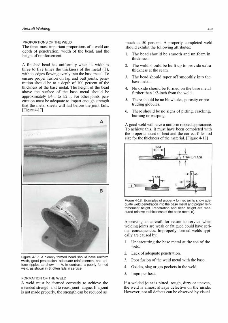
PROPORTIONS OF THE WELD The three most important proportions of a weld are depth of penetration, width of the bead, and the height of reinforcement.
A finished bead has uniformity when its width is three to five times the thickness of the metal (T), with its edges flowing evenly into the base metal. To ensure proper fusion on lap and butt joints, pene-tration should be to a depth of 100 percent of the thickness of the base metal. The height of the bead above the surface of the base metal should be approximately 1/4 T to 1/2 T. For other joints, pen-etration must be adequate to impart enough strength that the metal sheets will fail before the joint fails. [Figure 4-17]
Figure 4-17. A cleanly formed bead should have uniform width, good penetration, adequate reinforcement and uni-form ripples as shown in A. In contrast, a poorly formed weld, as shown in B, often fails in service.
FORMATION OF THE WELD A weld must be formed correctly to achieve the intended strength and to resist joint fatigue. If a joint is not made properly, the strength can be reduced as
much as 50 percent. A properly completed weld should exhibit the following attributes: 1. The bead should be smooth and uniform in
thickness. 2. The weld should be built up to provide extra
thickness at the seam. 3. The bead should taper off smoothly into the
base metal. 4. No oxide should be formed on the base metal
further than 1/2-inch from the weld. 5. There should be no blowholes, porosity or pro
truding globules.
6. There should be no signs of pitting, cracking, burning or warping.
A good weld will have a uniform rippled appearance. To achieve this, it must have been completed with the proper amount of heat and the correct filler rod size for the thickness of the material. [Figure 4-18]
Figure 4-18. Examples of properly formed joints show ade-quate weld penetration into the base metal and proper rein-forcement height. Penetration and bead height are mea-sured relative to thickness of the base metal (t).
Approving an aircraft for return to service when welding joints are weak or fatigued could have seri-ous consequences. Improperly formed welds typi-cally are caused by: 1. Undercutting the base metal at the toe of the
weld. 2. Lack of adequate penetration. 3. Poor fusion of the weld metal with the base. 4. Oxides, slag or gas pockets in the weld. 5. Improper heat.
If a welded joint is pitted, rough, dirty or uneven, the weld is almost always defective on the inside. However, not all defects can be observed by visual
4-70 Aircraft Welding
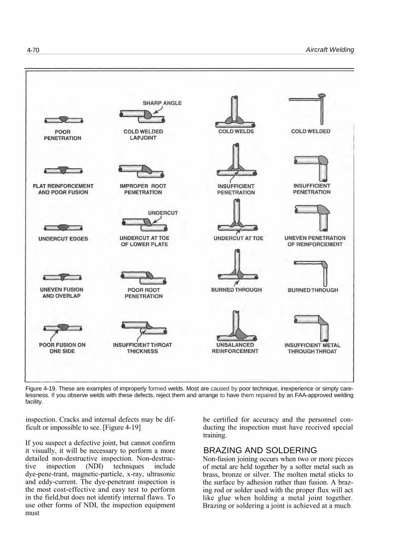
Figure 4-19. These are examples of improperly formed welds. Most are caused by poor technique, inexperience or simply care-lessness. If you observe welds with these defects, reject them and arrange to have them repaired by an FAA-approved welding facility.
inspection. Cracks and internal defects may be dif-ficult or impossible to see. [Figure 4-19]
If you suspect a defective joint, but cannot confirm it visually, it will be necessary to perform a more detailed non-destructive inspection. Non-destruc-tive inspection (NDI) techniques include dye-pene-trant, magnetic-particle, x-ray, ultrasonic and eddy-current. The dye-penetrant inspection is the most cost-effective and easy test to perform in the field,but does not identify internal flaws. To use other forms of NDI, the inspection equipment must
be certified for accuracy and the personnel con-ducting the inspection must have received special training.
BRAZING AND SOLDERING Non-fusion joining occurs when two or more pieces of metal are held together by a softer metal such as brass, bronze or silver. The molten metal sticks to the surface by adhesion rather than fusion. A braz-ing rod or solder used with the proper flux will act like glue when holding a metal joint together. Brazing or soldering a joint is achieved at a much
Aircraft Welding 4-11
lower temperature than fusion welding. Since brazed or soldered joints are not as strong as fusion-welded joints, they are not typically used in aircraft structural applications. Instead, brazing and soldering are used widely in electrical connectors, fuel and hydraulic line fittings, and many other low stress applications.
TORCH BRAZING Brazing is a form of metal joining in which an iron-free metal is used as a cohesive material. The non-ferrous material, usually brass or bronze, is melted with an oxyacetylene torch at a temperature below that of the base metal, but above 800 F. There are actually two operations that may be performed by brazing. One operation is referred to as braze welding, in which two metals are joined together in much the same manner as fusion welding, except that the filler material does not fuse into the base metal. Because braze welding does not provide the strength of fusion welds, it is seldom used in aircraft structures. The other operation is simply referred to as brazing, and involves melting cohesive brazing metal near closely fitting parts. The cohesive metal, once melted, flows between close-fitting metal surfaces by capillary action to form a tight seal or joint. When the joint cools, it forms a bond between the two metals. For this action to occur properly, the metal must be absolutely clean.
Flux is used to clean the surfaces of the metal being joined. Brazing flux has a caustic base which, when heated, turns to liquid. It washes away oxides and impurities that may have formed on the surfaces of the metals. A flux coating on a filler rod allows it to flow when melted and to adhere to a base metal sur-face. The term adhesion, as applied to brazing, means the molten filler material will flow into the pores of (but not fuse to) a joint. [Figure 4-20]
heat of welding would distort the part or destroy its heat treatment. For braze welding, the material must be mechanically cleaned to remove all oxidation and scale. The metal is then positioned, as it would be for regular welding. The end of the brazing rod is heated for about two inches and dipped into a borax-type flux. The flux sticks to the rod and will flow off as the rod melts on the base metal. Covering the joint with flux before welding also helps prevent the formation of oxides and produces a cleaner, stronger weld.
When braze welding, the torch should be adjusted to a neutral flame the same size as would be used for welding. Flame types and adjustment procedures are described later in section C of this chapter. The base metal should be heated to a cherry red. Keep the end of the brazing rod near the torch flame to keep it hot. When the metal is sufficiently heated, touch the rod to it so that the rod melts and flows onto the base metal. The width of a good braze bead should be about the same as a weld bead on the same thickness of material. Bead width is deter-mined by the distance the torch tip is held from the work the closer the tip, the wider the bead. However, the tip should be held at a sufficient dis-tance to prevent the base metal from becoming molten.
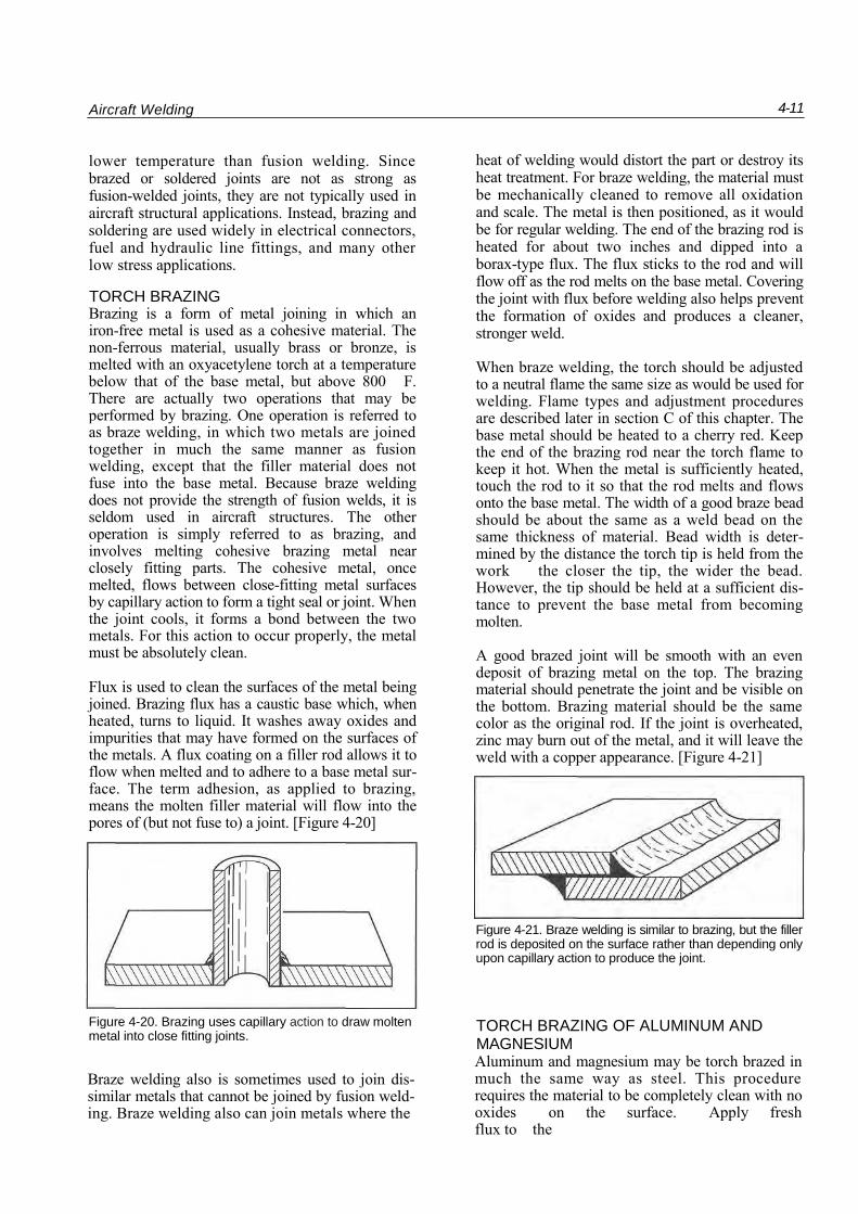
A good brazed joint will be smooth with an even deposit of brazing metal on the top. The brazing material should penetrate the joint and be visible on the bottom. Brazing material should be the same color as the original rod. If the joint is overheated, zinc may burn out of the metal, and it will leave the weld with a copper appearance. [Figure 4-21]
Figure 4-20. Brazing uses capillary action to draw molten metal into close fitting joints.
Braze welding also is sometimes used to join dis-similar metals that cannot be joined by fusion weld-ing. Braze welding also can join metals where the
TORCH BRAZING OF ALUMINUM AND MAGNESIUM Aluminum and magnesium may be torch brazed in much the same way as steel. This procedure requires the material to be completely clean with no oxides on the surface. Apply fresh flux to the
Figure 4-21. Braze welding is similar to brazing, but the filler rod is deposited on the surface rather than depending only upon capillary action to produce the joint.
4-72 Aircraft Welding
surface, and then use a soft, neutral flame to heat the material until the flux melts. As soon as the flux starts to flow, touch the rod to the material. The rod will melt and flow into the joint. Allow the joint to cool, and scrub every trace of the flux with an acid wash. Rinse away all traces of the acid with plenty of hot water. It is especially important to thoroughly remove all flux from magnesium parts because it can cause severe corrosion.
TORCH SOLDERING Soldering is similar to brazing, using many of the same techniques and devices as when making brazed joints. Brazing materials normally melt at temperatures above 800 F, while solders melt at temperatures considerably lower than this. As with brazing,the oxyacetylene welding torch is some-times used for soldering as well as brazing.
SOFT SOLDERING While there is very little use for soldered joints in aircraft structures, a technician may need to solder joints in an air-conditioning system or other non-structural application.
The basic principle of soldering is similar to that of brazing in that a joint is made with a close fit between the parts. The joint is fluxed and uniformly heated with a soft flame. The solder is melted by touching it to the metal at the edge of the joint, and it is pulled by capillary action into the joint.
Fluxes used for soldering are an important part of the system. The flux dissolves any oxides that are on the surface and prevents the formation of addi-
tional oxides until the joint is covered with the sol-der. Each different type of metal to be soldered has a recommended flux, which can be found in manu-facturers' guides or in soldering reference hand-books.
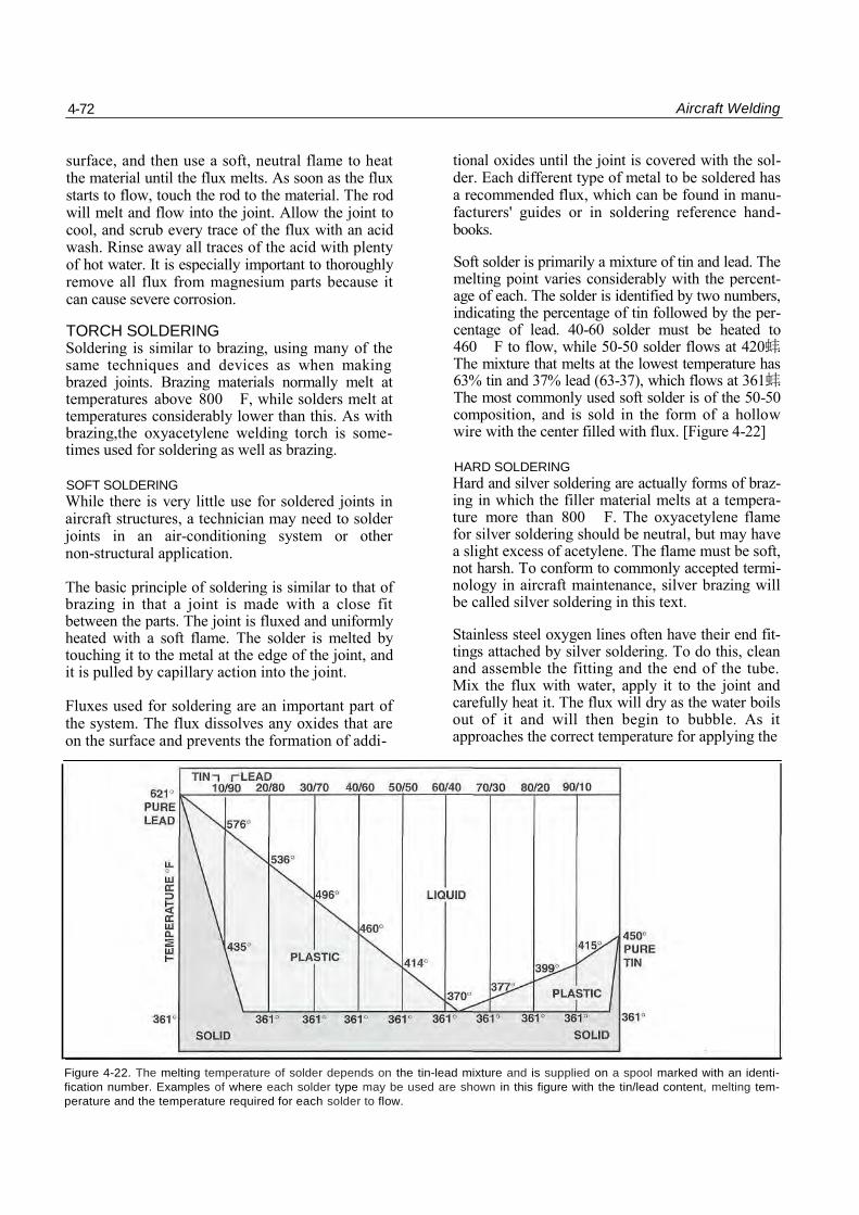
Soft solder is primarily a mixture of tin and lead. The melting point varies considerably with the percent-age of each. The solder is identified by two numbers, indicating the percentage of tin followed by the per-centage of lead. 40-60 solder must be heated to 460 F to flow, while 50-50 solder flows at 420蚌. The mixture that melts at the lowest temperature has 63% tin and 37% lead (63-37), which flows at 361蚌. The most commonly used soft solder is of the 50-50 composition, and is sold in the form of a hollow wire with the center filled with flux. [Figure 4-22]
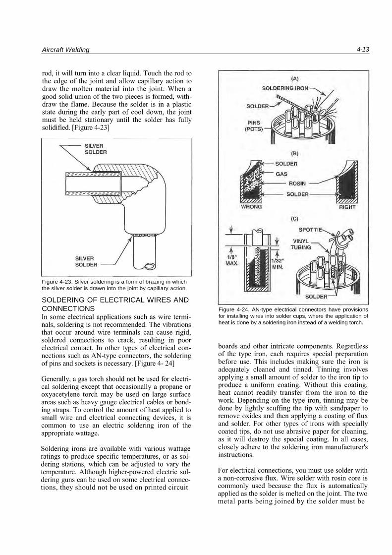
HARD SOLDERING Hard and silver soldering are actually forms of braz-ing in which the filler material melts at a tempera-ture more than 800 F. The oxyacetylene flame for silver soldering should be neutral, but may have a slight excess of acetylene. The flame must be soft, not harsh. To conform to commonly accepted termi-nology in aircraft maintenance, silver brazing will be called silver soldering in this text.
Stainless steel oxygen lines often have their end fit-tings attached by silver soldering. To do this, clean and assemble the fitting and the end of the tube. Mix the flux with water, apply it to the joint and carefully heat it. The flux will dry as the water boils out of it and will then begin to bubble. As it approaches the correct temperature for applying the
Figure 4-22. The melting temperature of solder depends on the tin-lead mixture and is supplied on a spool marked with an identi-
fication number. Examples of where each solder type may be used are shown in this figure with the tin/lead content, melting tem-
perature and the temperature required for each solder to flow.
Aircraft Welding 4-13
rod, it will turn into a clear liquid. Touch the rod to the edge of the joint and allow capillary action to draw the molten material into the joint. When a good solid union of the two pieces is formed, with-draw the flame. Because the solder is in a plastic state during the early part of cool down, the joint must be held stationary until the solder has fully solidified. [Figure 4-23]
Figure 4-23. Silver soldering is a form of brazing in which
the silver solder is drawn into the joint by capillary action.
SOLDERING OF ELECTRICAL WIRES AND
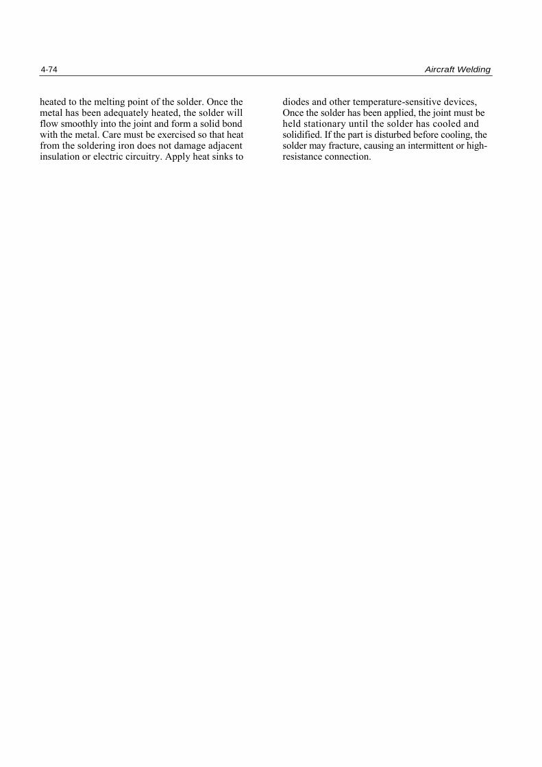
CONNECTIONS In some electrical applications such as wire termi-nals, soldering is not recommended. The vibrations that occur around wire terminals can cause rigid, soldered connections to crack, resulting in poor electrical contact. In other types of electrical con-nections such as AN-type connectors, the soldering of pins and sockets is necessary. [Figure 4- 24]
Generally, a gas torch should not be used for electri-cal soldering except that occasionally a propane or oxyacetylene torch may be used on large surface areas such as heavy gauge electrical cables or bond-ing straps. To control the amount of heat applied to small wire and electrical connecting devices, it is common to use an electric soldering iron of the appropriate wattage.
Soldering irons are available with various wattage ratings to produce specific temperatures, or as sol-dering stations, which can be adjusted to vary the temperature. Although higher-powered electric sol-dering guns can be used on some electrical connec-tions, they should not be used on printed circuit
Figure 4-24. AN-type electrical connectors have provisions
for installing wires into solder cups, where the application of
heat is done by a soldering iron instead of a welding torch.
boards and other intricate components. Regardless of the type iron, each requires special preparation before use. This includes making sure the iron is adequately cleaned and tinned. Tinning involves applying a small amount of solder to the iron tip to produce a uniform coating. Without this coating, heat cannot readily transfer from the iron to the work. Depending on the type iron, tinning may be done by lightly scuffing the tip with sandpaper to remove oxides and then applying a coating of flux and solder. For other types of irons with specially coated tips, do not use abrasive paper for cleaning, as it will destroy the special coating. In all cases, closely adhere to the soldering iron manufacturer's instructions.
For electrical connections, you must use solder with a non-corrosive flux. Wire solder with rosin core is commonly used because the flux is automatically applied as the solder is melted on the joint. The two metal parts being joined by the solder must be
4-74 Aircraft Welding
heated to the melting point of the solder. Once the diodes and other temperature-sensitive devices, metal has been adequately heated, the solder will Once the solder has been applied, the joint must be flow smoothly into the joint and form a solid bond held stationary until the solder has cooled and with the metal. Care must be exercised so that heat solidified. If the part is disturbed before cooling, the from the soldering iron does not damage adjacent solder may fracture, causing an intermittent or high- insulation or electric circuitry. Apply heat sinks to resistance connection.
ADVANCED WELDING AND REPAIRS
Repair of aircraft structures on modern aircraft requires more technical welding proficiency than perhaps may have been necessary before. Advances in aircraft materials and in the design of airframe structures have demanded improved welding processes and techniques. The use of basic gas welding to repair structures has generally been replaced by inert gas welding processes, usually Gas Tungsten Arc Welding, or TIG. Improvements in the welding process has also made it necessary to modify welding techniques based on the type of material being welded.
Repair of damaged aircraft structures is also more technically demanding than it may have been in the earlier types of aircraft. Specific rules and FAA requirements now dictate a much more deliberate and planned approach to complicated repairs. A technically simplistic approach to repair of aircraft structures is no longer realistic.
Technicians need to develop an appreciation and understanding of advanced welding techniques and repairs. Although typically not expert welders, air-craft technicians are charged with the ultimate responsibility of inspecting and approving the results of these maintenance activities. General con-cepts for advanced welding are introduced in this section, however the specific manufacturer's recom-mendations and guidance should be followed explicitly when welding on any aircraft compo-nents.
ADVANCED WELDING Aircraft construction has migrated from wood struc-tures and fabric covers to aluminum and other strong, lightweight materials. Each type of metal used in constructing or repairing an aircraft has unique properties that should be considered in the welding process.
GAS WELDING ALUMINUM Aluminum has a reputation for being difficult to weld because it does not change its color as it nears its melting temperature. It can be solid one moment
and the next it melts through, leaving a hole. With practice though, aluminum welding can be done as readily as steel.
Most aluminum welding is done with a gas-shielded electric arc, but there are times when aluminum is welded with either acetylene or hydrogen gas. Hydrogen is preferred because of its cleaner flame and less risk of oxidizing the joint. Hydrogen burns with much less heat than acetylene. For an equal thickness of metal, hydrogen requires a larger tip than would be used when welding with acetylene.
Prepare the metal for welding by cleaning it with an aluminum or hog bristle brush. A stainless steel brush or stainless steel wool may also be used. Other types of steel brushes or steel wool should not be used, as tiny steel particles may become embed-ded in the soft aluminum and contaminate the weld. Support both pieces adequately before weld-ing as the metal at the joint will lose all its strength and rigidity as it melts.
Heat the metal and apply flux to the pieces that will be joined and to the welding rod. Use light blue welding goggles in order to see the very subtle changes in appearance of the metal as it approaches melting. The surface of the metal should be lightly wiped with the welding rod. As soon as the metal feels slightly soft, allow the rod to stay in contact and melt with the metal.
The flame used for welding aluminum should be neutral or slightly carburizing, to reduce the possi-bility of the metal being oxidized during the weld-ing process. A properly formed bead will be uni-form in width and height. It also will have a bright shiny surface, the same color as the filler rod. If the weld is oxidized, it will have a powdery white appearance and a rough surface. If the flame was too carburizing, the weld will have a dirty appearance from the extra carbon. When the weld is complete, scrub off all traces of the welding flux with hot water and a hog bristle brush. Any flux left on the metal will cause it to corrode.
4-76 Aircraft Welding
TIG WELDING ALUMINUM TIG welding is the preferred method for welding alu-minum. The heat from tho TIG torch is much more concentrated than it is with an oxygen torch. This concentration has less effect on the remainder of the structure and does not affect the heat treatment as extensively as gas welding. In either case, after weld-ing a heat treated aluminum part, the part must be re-heat treated before reinstallation on the aircraft. In addition, the inert gas provides shielding of the work area and resists the development of aluminum oxides.
To prepare aluminum for welding, it must first be cleaned as thoroughly as possible. It should be brushed with a hog bristle or stainless steel brush to remove the oxide film that is on the surface. Afterward, it should be scrubbed with an appropri-ate solvent. This should be done immediately prior to initiating the weld, because bare aluminum will begin oxidizing very quickly.
Use the electrode recommended by the manufac-turer of the welding equipment for the thickness of metal being welded. Preparation of the electrode, the amount and type of current, and the flow of gas will also be described in the manufacturer's instructions. Hold the torch over the work and lower it until the arc starts. The superimposed high-frequency signal will allow the arc to start without touching the elec-trode to the work.With the arc established, the sur-face of the aluminum must be monitored so that the rod can be added before the metal melts through. When the surface begins to appear frosty and then starts to lift just a little, it is time to touch the rod to the surface. Once initiated, continue the weld by melting the rod along with the surface.
TIG WELDING MAGNESIUM Magnesium is an extremely active metal whose oxi-dation rate increases as its temperature is raised. Magnesium burns at a very high temperature and pro-duces oxygen as a byproduct of combustion, there-fore, is not extinguishable by normal means. Special agents must be used that cool the magnesium thereby extinguishing the fire. Magnesium melts at tempera-tures near that of aluminum, but the oxides that form on its surface melt at a far higher temperature. In order to make a successful weld, these oxides must be removed. Before starting the weld, the oxides must be removed with a hog bristle or stainless steel brush and the surface scrubbed with an appropriate solvent. Using AC current with high-frequency arc stabiliza-tion and an inert gas keeps the weld area from being contaminated. The filler rod used for magnesium should be the same as the metal itself. The producer of the metal may recommend other types of rods.
TIG WELDING TITANIUM Titanium, beryllium and zirconium are reactive metals, and welding them presents special prob-lems. These metals have a strong affinity for oxy-gen and nitrogen when they are heated to a high temperature, and when they combine, they form stable compounds. The oxides that form resist further oxidation. Minor impurities in these met-als will cause them to become brittle. Special care must be taken to be sure that all of their oxides and any surface contaminants are removed before they are welded. Titanium and other reactive metals must be welded in an atmosphere that allows no oxygen or nitrogen to contact the hot metal.
When welding titanium, use straight polarity DC current and a thoriated tungsten electrode of the smallest diameter that will carry the welding cur-rent. Argon gas, a large gas nozzle and a trailing shield is used to keep air away from the hot metal.
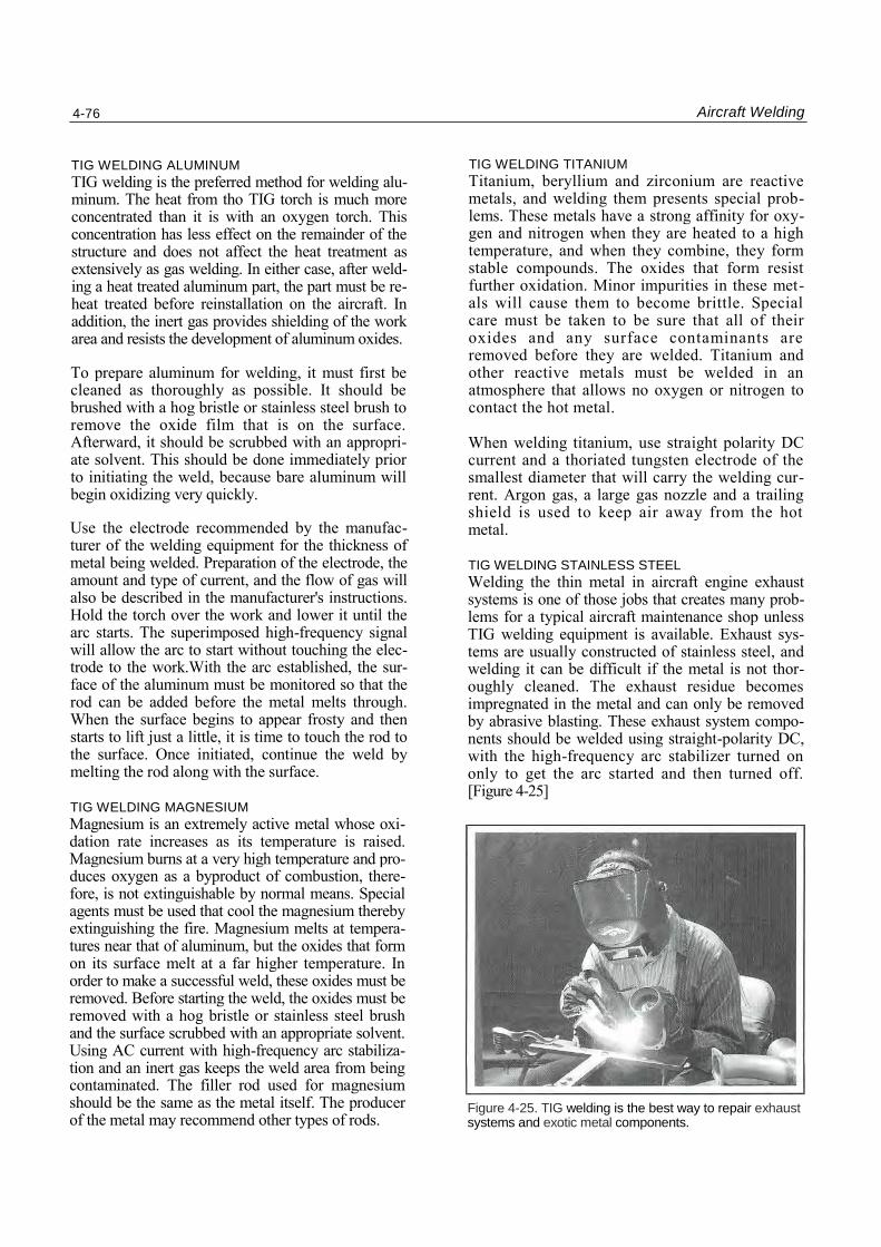
TIG WELDING STAINLESS STEEL Welding the thin metal in aircraft engine exhaust systems is one of those jobs that creates many prob-lems for a typical aircraft maintenance shop unless TIG welding equipment is available. Exhaust sys-tems are usually constructed of stainless steel, and welding it can be difficult if the metal is not thor-oughly cleaned. The exhaust residue becomes impregnated in the metal and can only be removed by abrasive blasting. These exhaust system compo-nents should be welded using straight-polarity DC, with the high-frequency arc stabilizer turned on only to get the arc started and then turned off. [Figure 4-25]
Figure 4-25. TIG welding is the best way to repair exhaust systems and exotic metal components.
Aircraft Welding 4-17
STRUCTURAL WELDING REPAIRS Welded repairs to aircraft structures by an A&P tech-nician requires a high degree of professionalism and judgement. As an astute aircraft technician, you should have recognized by now that welding of alu-minum, stainless steel and exotic metals requires special tools, training and techniques. The average technician usually will not have the expertise neces-sary to perform airworthy repairs to these types of structures and components. Recognition of the need to enlist the aid of specialists is one of the hallmarks of a good A&P mechanic. Consider that an improper weld on a structural part of the aircraft could cause failures with serious results. Welded repairs made directly to the airframe must be correctly done in order to retain the design strength of the aircraft. The airframe along "with the engine mounts and landing gear assemblies absorb the highest mechanical loads and vibrations in the aircraft.
Before attempting any welding repair of an aircraft structure, it is a good policy to consult with the ser-vice department of the aircraft manufacturer. The complexity of modern aircraft and the responsibil-ity placed on a technician requires obtaining the best information prior to making a repair decision.
Although you may be reasonably qualified to per-form the repair, it is advisable to consider another option. While the integrity of the repair is the responsibility of a licensed A&P technician, using the skill and experience of a welding specialist may be a wise practice. You may choose to design the repair, cut and fit the pieces, and then deliver the job to a professional welder for completion.
The repair must be designed so it will conform to approved data. If such data does not exist that exactly fits the needed repair, the proposed design must be submitted to the FAA Flight Standards District Office for approval. The FAA must approve any proposed repair that is not listed in the manu-facturer's structural repair manual.
Any structural repair decision a technician makes should be based on a clear understanding of specific welded repairs and techniques. A closer look at spe-cific types of repairs and techniques is covered in the next section.
STRUCTURAL REPAIRS Most repairs requiring welding will be outlined in detail in a structural repair manual for the part being repaired. Some will require design and approval for a repair. This section outlines the gen-eral procedures that will be employed in specific
types of repairs. This is only an orientation to these types of repairs and any actual repair must be per-formed according to approved data and procedures.
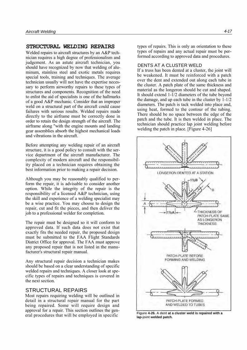
DENTS AT A CLUSTER WELD If a truss has been dented at a cluster, the joint will be weakened. It must be reinforced with a patch over the dent and extended out along each tube in the cluster. A patch plate of the same thickness and material as the longeron should be cut and shaped. It should extend 1-1/2 diameters of the tube beyond the damage, and up each tube in the cluster by 1-1/2 diameters. The patch is tack welded into place and, using heat, formed to the contour of the tubing. There should be no space between the edge of the patch and the tube. It is then welded in place. The technician should practice lap joint welding before welding the patch in place. [Figure 4-26]
Figure 4-26. A dent at a cluster weld is repaired with a
lap-joint welded patch.
4-18 Aircraft Welding
DENTS BETWEEN CLUSTERS If a longeron or cross member is dented or cracked between clusters, it may be repaired by welding a sleeve over the damage. First, straighten the dent as much as possible and then straighten the tube. If the tube is cracked, stop drill the ends of the crack to prevent it from extending any further.
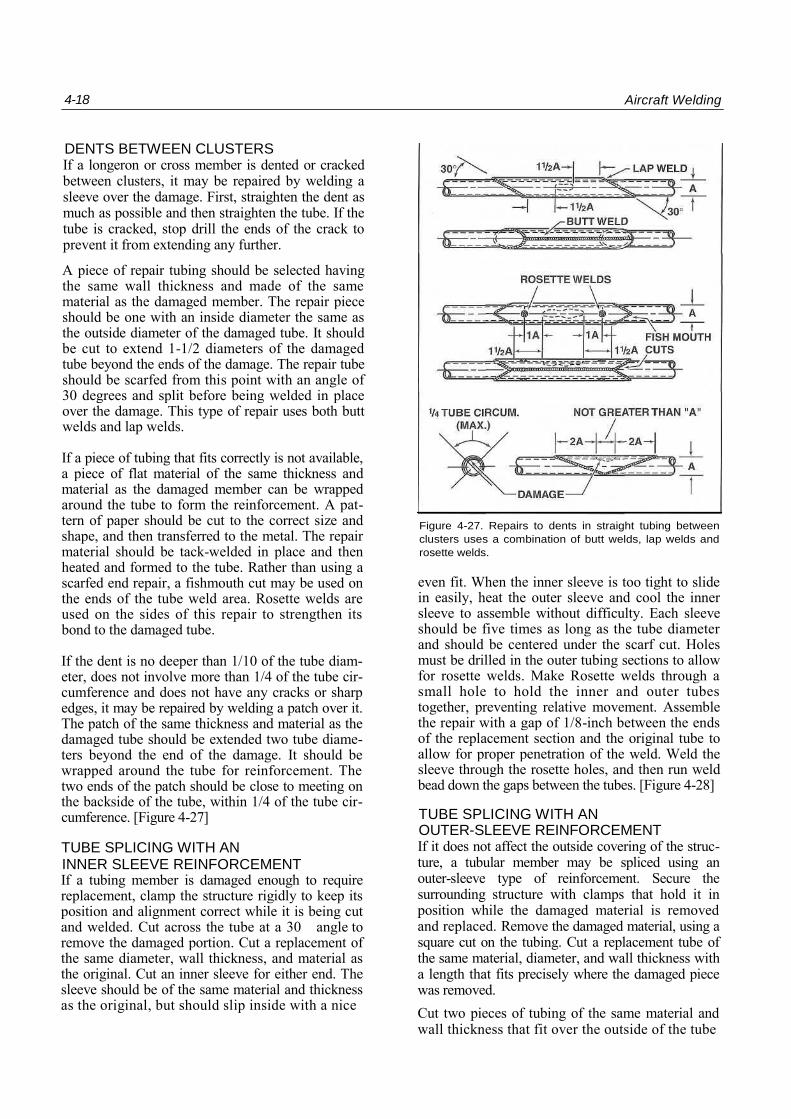
A piece of repair tubing should be selected having the same wall thickness and made of the same material as the damaged member. The repair piece should be one with an inside diameter the same as the outside diameter of the damaged tube. It should be cut to extend 1-1/2 diameters of the damaged tube beyond the ends of the damage. The repair tube should be scarfed from this point with an angle of 30 degrees and split before being welded in place over the damage. This type of repair uses both butt welds and lap welds.
If a piece of tubing that fits correctly is not available, a piece of flat material of the same thickness and material as the damaged member can be wrapped around the tube to form the reinforcement. A pat-tern of paper should be cut to the correct size and shape, and then transferred to the metal. The repair material should be tack-welded in place and then heated and formed to the tube. Rather than using a scarfed end repair, a fishmouth cut may be used on the ends of the tube weld area. Rosette welds are used on the sides of this repair to strengthen its bond to the damaged tube.
If the dent is no deeper than 1/10 of the tube diam-eter, does not involve more than 1/4 of the tube cir-cumference and does not have any cracks or sharp edges, it may be repaired by welding a patch over it. The patch of the same thickness and material as the damaged tube should be extended two tube diame-ters beyond the end of the damage. It should be wrapped around the tube for reinforcement. The two ends of the patch should be close to meeting on the backside of the tube, within 1/4 of the tube cir-cumference. [Figure 4-27]
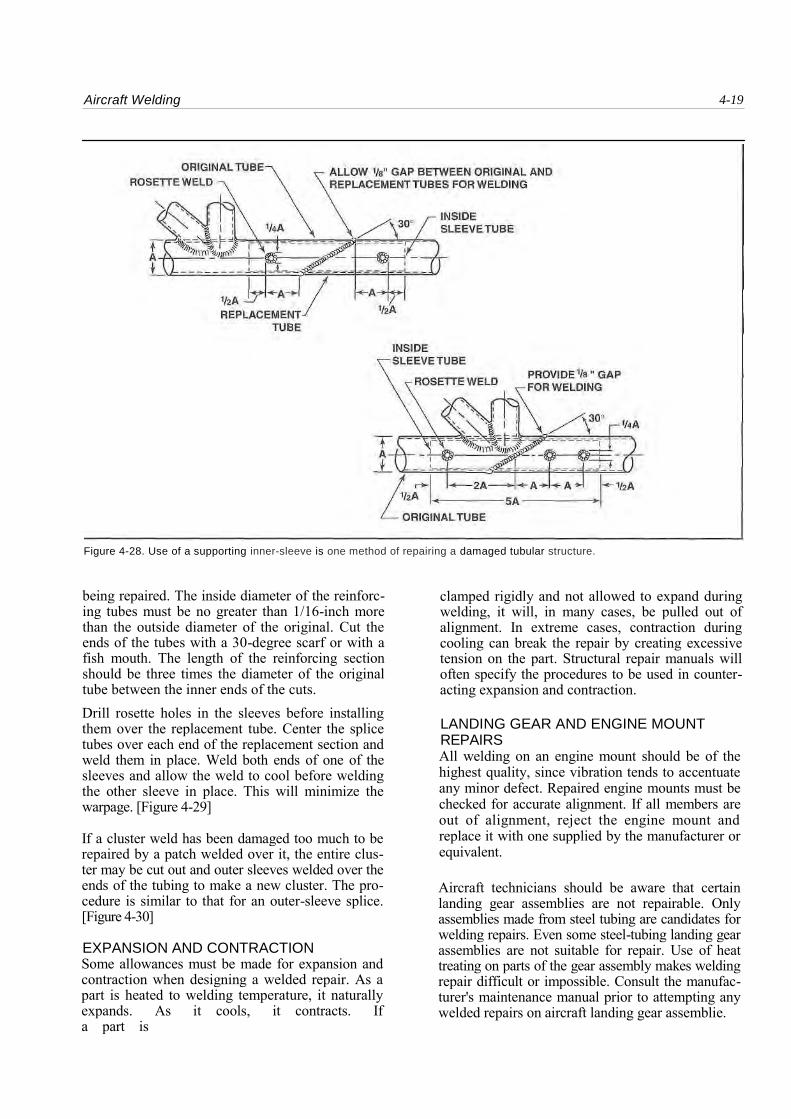
TUBE SPLICING WITH AN INNER SLEEVE REINFORCEMENT If a tubing member is damaged enough to require replacement, clamp the structure rigidly to keep its position and alignment correct while it is being cut and welded. Cut across the tube at a 30 angle to remove the damaged portion. Cut a replacement of the same diameter, wall thickness, and material as the original. Cut an inner sleeve for either end. The sleeve should be of the same material and thickness as the original, but should slip inside with a nice
Figure 4-27. Repairs to dents in straight tubing between
clusters uses a combination of butt welds, lap welds and
rosette welds.
even fit. When the inner sleeve is too tight to slide in easily, heat the outer sleeve and cool the inner sleeve to assemble without difficulty. Each sleeve should be five times as long as the tube diameter and should be centered under the scarf cut. Holes must be drilled in the outer tubing sections to allow for rosette welds. Make Rosette welds through a small hole to hold the inner and outer tubes together, preventing relative movement. Assemble the repair with a gap of 1/8-inch between the ends of the replacement section and the original tube to allow for proper penetration of the weld. Weld the sleeve through the rosette holes, and then run weld bead down the gaps between the tubes. [Figure 4-28]
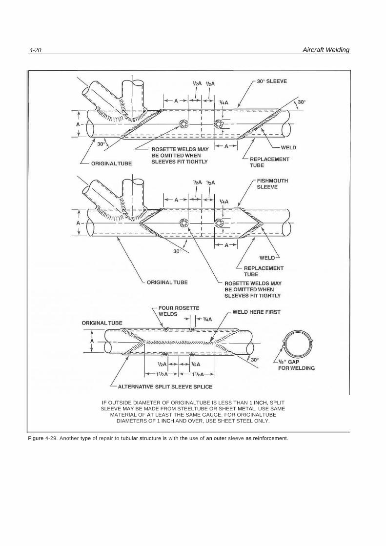
TUBE SPLICING WITH AN OUTER-SLEEVE REINFORCEMENT If it does not affect the outside covering of the struc-ture, a tubular member may be spliced using an outer-sleeve type of reinforcement. Secure the surrounding structure with clamps that hold it in position while the damaged material is removed and replaced. Remove the damaged material, using a square cut on the tubing. Cut a replacement tube of the same material, diameter, and wall thickness with a length that fits precisely where the damaged piece was removed. Cut two pieces of tubing of the same material and wall thickness that fit over the outside of the tube
Aircraft Welding 4-19
Figure 4-28. Use of a supporting inner-sleeve is one method of repairing a damaged tubular structure.
being repaired. The inside diameter of the reinforc-ing tubes must be no greater than 1/16-inch more than the outside diameter of the original. Cut the ends of the tubes with a 30-degree scarf or with a fish mouth. The length of the reinforcing section should be three times the diameter of the original tube between the inner ends of the cuts. Drill rosette holes in the sleeves before installing them over the replacement tube. Center the splice tubes over each end of the replacement section and weld them in place. Weld both ends of one of the sleeves and allow the weld to cool before welding the other sleeve in place. This will minimize the warpage. [Figure 4-29]
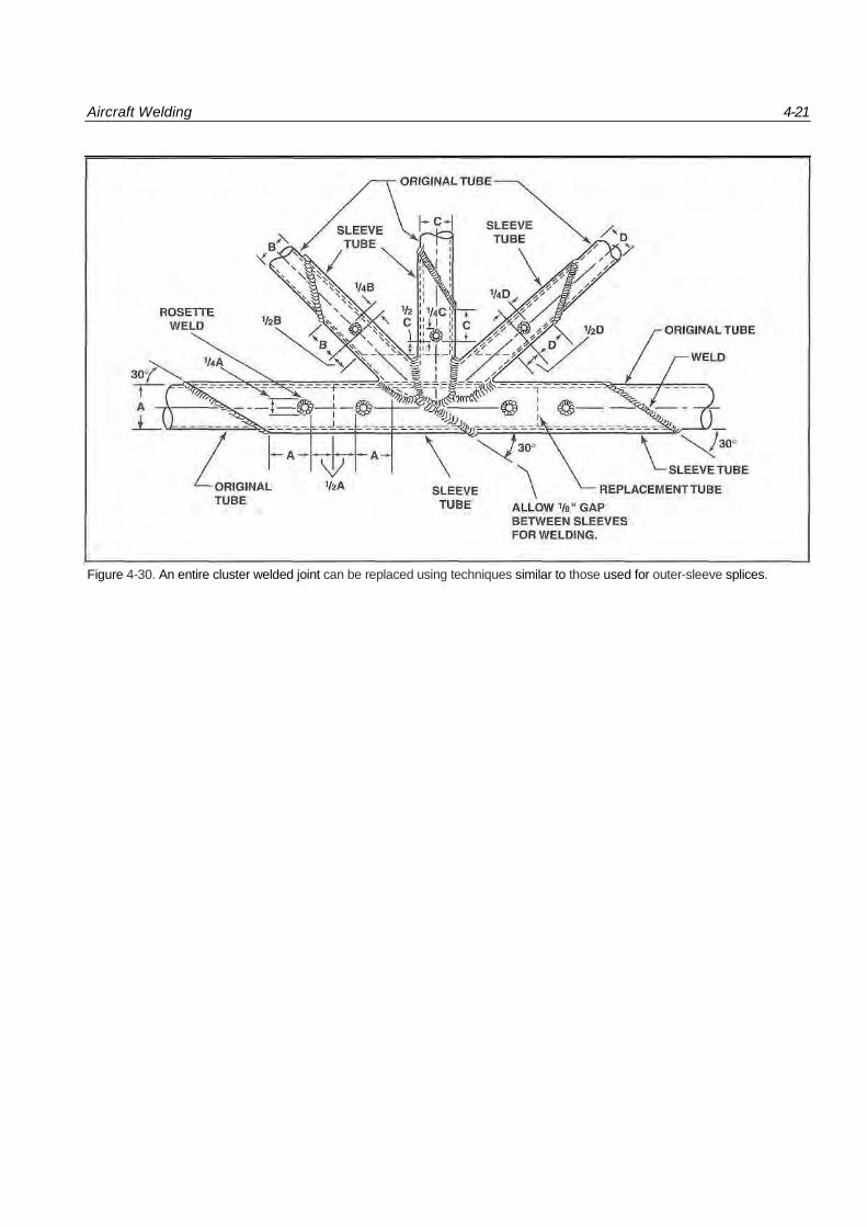
If a cluster weld has been damaged too much to be repaired by a patch welded over it, the entire clus-ter may be cut out and outer sleeves welded over the ends of the tubing to make a new cluster. The pro-cedure is similar to that for an outer-sleeve splice. [Figure 4-30]
EXPANSION AND CONTRACTION Some allowances must be made for expansion and contraction when designing a welded repair. As a part is heated to welding temperature, it naturally expands. As it cools, it contracts. If a part is
clamped rigidly and not allowed to expand during welding, it will, in many cases, be pulled out of alignment. In extreme cases, contraction during cooling can break the repair by creating excessive tension on the part. Structural repair manuals will often specify the procedures to be used in counter-acting expansion and contraction.
LANDING GEAR AND ENGINE MOUNT REPAIRS All welding on an engine mount should be of the highest quality, since vibration tends to accentuate any minor defect. Repaired engine mounts must be checked for accurate alignment. If all members are out of alignment, reject the engine mount and replace it with one supplied by the manufacturer or equivalent.
Aircraft technicians should be aware that certain landing gear assemblies are not repairable. Only assemblies made from steel tubing are candidates for welding repairs. Even some steel-tubing landing gear assemblies are not suitable for repair. Use of heat treating on parts of the gear assembly makes welding repair difficult or impossible. Consult the manufac-turer's maintenance manual prior to attempting any welded repairs on aircraft landing gear assemblie.
4-20 Aircraft Welding
IF OUTSIDE DIAMETER OF ORIGINALTUBE IS LESS THAN 1 INCH, SPLIT SLEEVE MAY BE MADE FROM STEELTUBE OR SHEET METAL. USE SAME
MATERIAL OF AT LEAST THE SAME GAUGE. FOR ORIGINALTUBE DIAMETERS OF 1 INCH AND OVER, USE SHEET STEEL ONLY.
Figure 4-29. Another type of repair to tubular structure is with the use of an outer sleeve as reinforcement.
Aircraft Welding 4-21
Figure 4-30. An entire cluster welded joint can be replaced using techniques similar to those used for outer-sleeve splices.
BASIC GAS WELDING
Even though tungsten inert gas (TIG) welding is the accepted welding method for modern aircraft, you need to understand basic gas welding before learn-ing these advanced techniques. This includes knowledge of the gases and equipment used, as well as equipment set-up, operation and shutdown. Gas welding, more than most aspects of airframe main-tenance, requires constant attention to safety prac-tices and proper use of safety equipment.
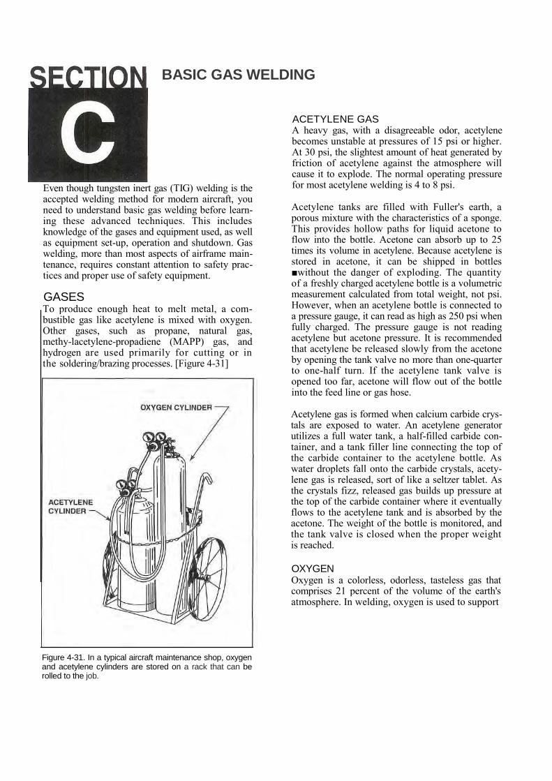
GASES To produce enough heat to melt metal, a com-bustible gas like acetylene is mixed with oxygen. Other gases, such as propane, natural gas, methy-lacetylene-propadiene (MAPP) gas, and hydrogen are used primarily for cutting or in the soldering/brazing processes. [Figure 4-31]
Figure 4-31. In a typical aircraft maintenance shop, oxygen and acetylene cylinders are stored on a rack that can be rolled to the job.
ACETYLENE GAS A heavy gas, with a disagreeable odor, acetylene becomes unstable at pressures of 15 psi or higher. At 30 psi, the slightest amount of heat generated by friction of acetylene against the atmosphere will cause it to explode. The normal operating pressure for most acetylene welding is 4 to 8 psi.
Acetylene tanks are filled with Fuller's earth, a porous mixture with the characteristics of a sponge. This provides hollow paths for liquid acetone to flow into the bottle. Acetone can absorb up to 25 times its volume in acetylene. Because acetylene is stored in acetone, it can be shipped in bottles ■without the danger of exploding. The quantity of a freshly charged acetylene bottle is a volumetric measurement calculated from total weight, not psi. However, when an acetylene bottle is connected to a pressure gauge, it can read as high as 250 psi when fully charged. The pressure gauge is not reading acetylene but acetone pressure. It is recommended that acetylene be released slowly from the acetone by opening the tank valve no more than one-quarter to one-half turn. If the acetylene tank valve is opened too far, acetone will flow out of the bottle into the feed line or gas hose.
Acetylene gas is formed when calcium carbide crys-tals are exposed to water. An acetylene generator utilizes a full water tank, a half-filled carbide con-tainer, and a tank filler line connecting the top of the carbide container to the acetylene bottle. As water droplets fall onto the carbide crystals, acety-lene gas is released, sort of like a seltzer tablet. As the crystals fizz, released gas builds up pressure at the top of the carbide container where it eventually flows to the acetylene tank and is absorbed by the acetone. The weight of the bottle is monitored, and the tank valve is closed when the proper weight is reached.
OXYGEN Oxygen is a colorless, odorless, tasteless gas that comprises 21 percent of the volume of the earth's atmosphere. In welding, oxygen is used to support
Aircraft Welding 4-23
combustion. Oxygen must never be used in the pres-ence of petroleum-based substances because of the danger of a fire or explosion. For example, when high-pressure oxygen comes into contact with petroleum-based engine oil, it lowers its flash point to the level that a spark or minimal friction could set off an explosion. Extreme caution is required when welding on tanks that were once filled with gasoline, alcohol, hydraulic fluid or any other volatile substance. The tanks must be steam-cleaned thoroughly before beginning.
The flame color and pattern from the welding torch changes as the volume of oxygen relative to the acetylene is increased. As the oxygen valve is opened, the flame color changes from a dull orange to a brilliant whitish purple. This carbonizing flame is still relatively rich in acetylene. The intensity of the heat continues to increase with additional oxygen until the optimal mixture, and a neutral flame is reached. If the amount of oxygen is increased further, the flame changes from neu-tral to oxidizing. A neutral flame is 6,300 F and is used primarily when welding aircraft steel. A car-bonizing flame burns much cooler, and is used for brazing and soldering. An oxidizing flame is used for cutting.
EQUIPMENT Oxyacetylene welding equipment includes regula-tors, hoses, torches and lighters as well as personal safety equipment like welding goggles and gloves. It is essential to understand the operation and safety practices for this equipment.
PRESSURE REGULATORS Both oxygen and acetylene are supplied under a pressure far higher than is needed at the torch. A regulator reduces the pressure to a usable value. If the gases are supplied from a manifold system, a single-stage regulator is sufficient to control the pressure. However, most aircraft repair shops use bottled, high-pressure gases, which require two-stage regulators.
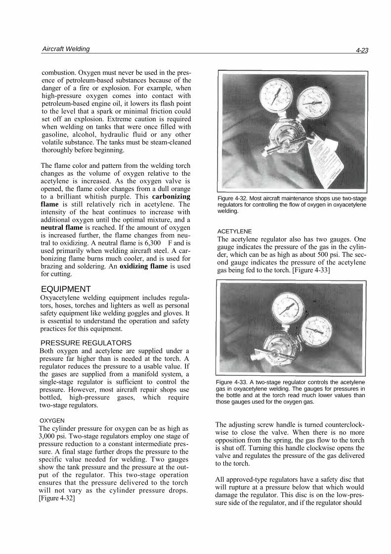
OXYGEN The cylinder pressure for oxygen can be as high as 3,000 psi. Two-stage regulators employ one stage of pressure reduction to a constant intermediate pres-sure. A final stage further drops the pressure to the specific value needed for welding. Two gauges show the tank pressure and the pressure at the out-put of the regulator. This two-stage operation ensures that the pressure delivered to the torch will not vary as the cylinder pressure drops. [Figure 4-32]
Figure 4-32. Most aircraft maintenance shops use two-stage regulators for controlling the flow of oxygen in oxyacetylene welding.
ACETYLENE The acetylene regulator also has two gauges. One gauge indicates the pressure of the gas in the cylin-der, which can be as high as about 500 psi. The sec-ond gauge indicates the pressure of the acetylene gas being fed to the torch. [Figure 4-33]
Figure 4-33. A two-stage regulator controls the acetylene gas in oxyacetylene welding. The gauges for pressures in the bottle and at the torch read much lower values than those gauges used for the oxygen gas.
The adjusting screw handle is turned counterclock-wise to close the valve. When there is no more opposition from the spring, the gas flow to the torch is shut off. Turning this handle clockwise opens the valve and regulates the pressure of the gas delivered to the torch.
All approved-type regulators have a safety disc that will rupture at a pressure below that which would damage the regulator. This disc is on the low-pres-sure side of the regulator, and if the regulator should
4-24 Aircraft Welding
leak, this disc will break before the regulator diaphragm is ruptured.
The oxygen regulator is similar to the one used for the acetylene gas, except that it is built for a much higher pressure.
In addition to a portable welding system, there is another type called the manifold system. The mani-fold system is a permanent setup with individual welding stations. The manifold system is often used in a welding shop or a welding school. A manifold system has two sets of pipes ne for oxygen and the other for acetylene gas. The gas bottles used in the manifold system are larger than those of the portable system. Gas pressure in the manifold sys-tem is set by a main system regulator connected to each gas tank. Each main pressure regulator has two gauges mounted on it, the one near the tank indi-cates bottle pressure and the other near the line indicates adjusted line pressure.
If the oxygen and acetylene are delivered to a per-manently installed welding bench from a manifold, there often is only one pressure gauge. It will be located at the bench and will indicate the pressure being delivered to the torch.
HOSES Acetylene and oxygen hoses connect the gas bottles to the welding torch. A typical system consists of the bottles with gas shutoff valves, regulators con-nected to each gas valve, and hoses that run from the regulators to the torch handle.
To prevent interchanging the hoses, the acetylene regulator connection has left-hand threads, while oxygen regulator connection has right-hand threads. The acetylene hose is red and the left-hand fittings can easily be recognized by the universal groove cut into the hex-sided coupling nuts. The oxygen hose
Figure 4-34.The oxygen and acetylene hose couplings have different threads to prevent inadvertently switching the hoses.
is green with right-hand threaded coupling nuts at each end. [Figure 4-34]
TORCHES There are two types of oxyacetylene welding torches: equal pressure and injector. The equal pres-sure type is most commonly used in aircraft weld-ing and uses cylinder gases. If the acetylene is sup-plied to the welding bench from a generator, an injector torch is used.
EQUAL PRESSURE TORCH An equal pressure torch consists of oxygen and acetylene on/off valves, a mixing chamber and a torch tip. This is the type of torch that is most often used with cylinder gases. The oxygen and acetylene are supplied to the torch at the same pressure, usu-ally between one and five psi, depending upon the thickness of the metal being welded.
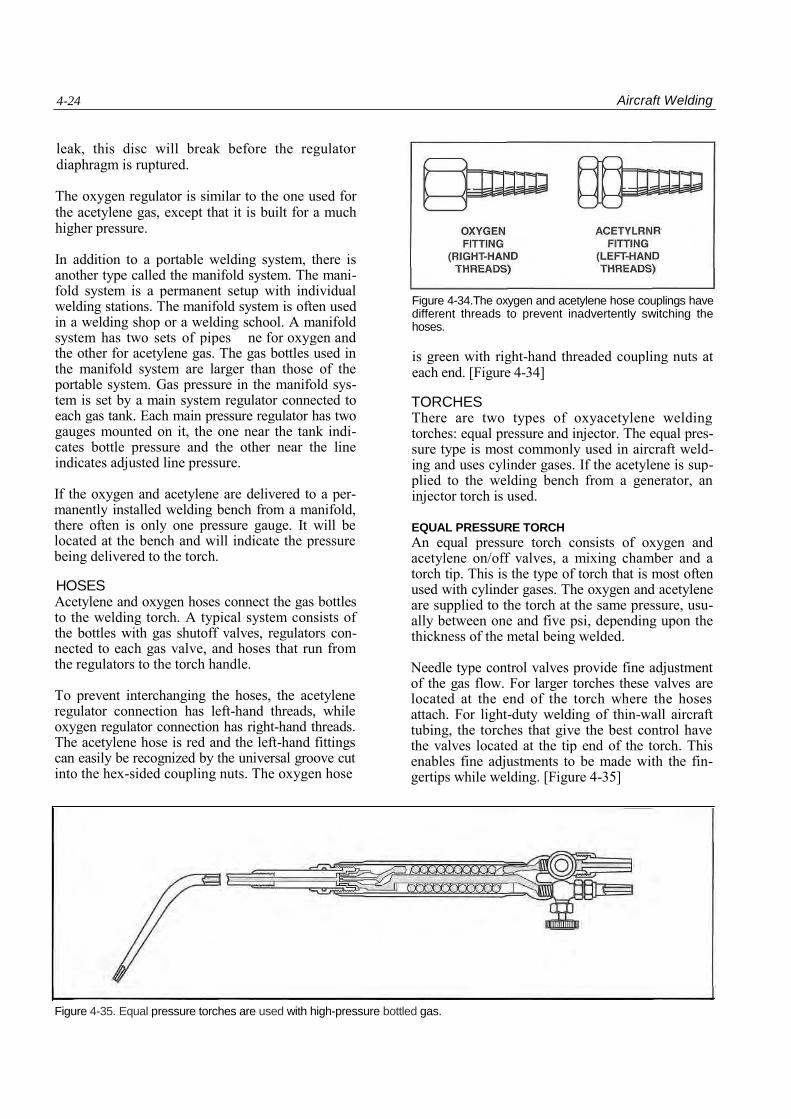
Needle type control valves provide fine adjustment of the gas flow. For larger torches these valves are located at the end of the torch where the hoses attach. For light-duty welding of thin-wall aircraft tubing, the torches that give the best control have the valves located at the tip end of the torch. This enables fine adjustments to be made with the fin-gertips while welding. [Figure 4-35]
Figure 4-35. Equal pressure torches are used with high-pressure bottled gas.
Aircraft Welding 4-25
The mixing chamber for equal pressure torches screws onto the torch body, and the tubes and tips screw into it. The gases flow into the mixing cham-ber through two separate tubes, where they are thor-oughly mixed before they are delivered to the tip.
While some torches utilize separate tips screwed onto a single-torch tube, a combination tip and tube, that screws directly into the mixing chamber, is more common. The manufacturer usually desig-nates the size of the tip. Common orifice sizes are 000, 00, 0, and 1-5, with larger tip sizes being desig-nated by larger numbers. The manufacturer usually lists the number drill size that corresponds to each size tip.
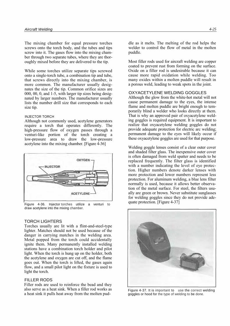
INJECTOR TORCH Although not commonly used, acetylene generators require a torch that operates differently. The high-pressure flow of oxygen passes through a venturi-like portion of the torch creating a low-pressure area to draw the low-pressure acetylene into the mixing chamber. [Figure 4-36]
Figure 4-36. Injector torches utilize a venturi to draw acetylene into the mixing chamber.
TORCH LIGHTERS Torches usually are lit with a flint-and-steel-type lighter. Matches should not be used because of the danger in carrying matches in the welding area. Metal popped from the torch could accidentally ignite them. Many permanently installed welding stations have a combination torch holder and pilot light. When the torch is hung up on the holder, both the acetylene and oxygen are cut off, and the flame goes out. When the torch is lifted, the gases again flow, and a small pilot light on the fixture is used to light the torch.
FILLER RODS Filler rods are used to reinforce the bead and they also serve as a heat sink. When a filler rod works as a heat sink it pulls heat away from the molten pud-
dle as it melts. The melting of the rod helps the welder to control the flow of metal in the molten puddle.
Most filler rods used for aircraft welding are copper coated to prevent rust from forming on the surface. Oxide on a filler rod is undesirable because it can cause more rapid oxidation while welding. Too many oxides within a molten puddle will result in a porous weld, leading to weak spots in the joint.
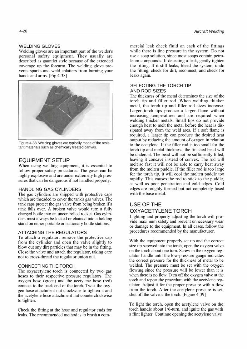
OXYACETYLENE WELDING GOGGLES Although the glow from the white-hot metal will not cause permanent damage to the eyes, the intense flame and molten puddle are bright enough to tem-porarily blind a welder who looks directly at them. That is why an approved pair of oxyacetylene weld-ing goggles is required equipment. It is important to realize that oxyacetylene welding goggles do not provide adequate protection for electric arc welding; permanent damage to the eyes will likely occur if these oxyacetylene goggles are used for that purpose.
Welding goggle lenses consist of a clear outer cover and shaded filter glass. The inexpensive outer cover is often damaged from weld spatter and needs to be replaced frequently. The filter glass is identified with a number indicating the level of eye protec-tion. Higher numbers denote darker lenses with more protection and lower numbers represent less protection. For aluminum welding, a blue lens filter normally is used, because it allows better observa-tion of the metal surface. For steel, the filters usu-ally are green or brown. Never substitute sunglasses for welding goggles since they do not provide ade-quate protection. [Figure 4-37]
Figure 4-37. It is important to use the correct welding goggles or hood for the type of welding to be done.
4-26 Aircraft Welding
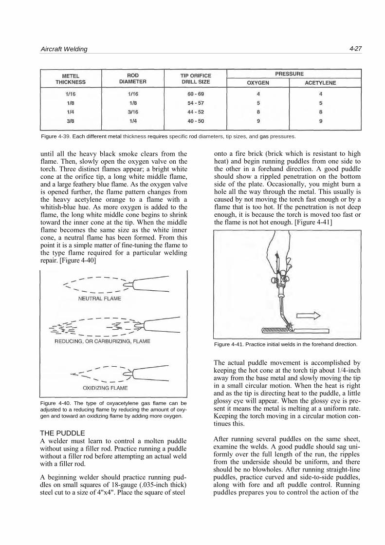
WELDING GLOVES Welding gloves are an important part of the welder's personal safety equipment. They usually are described as gauntlet style because of the extended coverage up the forearm. The welding glove pre-vents sparks and weld splatters from burning your hands and arms. [Fig 4-38]
Figure 4-38. Welding gloves are typically made of fire resis-tant materials such as chemically treated canvas.
EQUIPMENT SETUP When using welding equipment, it is essential to follow proper safety procedures. The gases can be highly explosive and are under extremely high pres-sures that can be dangerous if not handled properly.
HANDLING GAS CYLINDERS The gas cylinders are shipped with protective caps which are threaded to cover the tank's gas valves. The tank caps protect the gas valve from being broken if a tank falls over. A broken valve would turn a fully charged bottle into an uncontrolled rocket. Gas cylin-ders must always be locked or chained into a holding stand on either portable or stationary bottle stations.
ATTACHING THE REGULATORS To attach a regulator, remove the protective cap from the cylinder and open the valve slightly to blow out any dirt particles that may be in the fitting. Close the valve and attach the regulator, taking care not to cross-thread the regulator union nut.
CONNECTING THE TORCH The oxyacetylene torch is connected by two gas hoses to their respective pressure regulators. The oxygen hose (green) and the acetylene hose (red) connect to the back end of the torch. Twist the oxy-gen hose attachment nut clockwise to tighten it and the acetylene hose attachment nut counterclockwise to tighten.
Check the fitting at the hose and regulator ends for leaks. The recommended method is to brush a com-
mercial leak check fluid on each of the fittings while there is line pressure in the system. Do not use a soap solution, since most soaps contain petro-leum compounds. If detecting a leak, gently tighten the fitting. If it still leaks, bleed the system, undo the fitting, check for dirt, reconnect, and check for leaks again.
SELECTING THE TORCH TIP
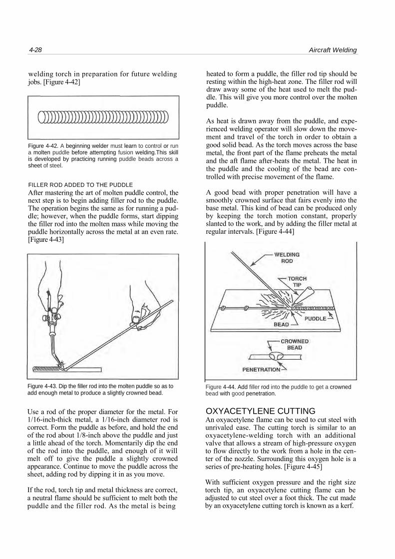
AND ROD SIZES The thickness of the metal determines the size of the torch tip and filler rod. When welding thicker metal, the torch tip and filler rod sizes increase. Larger torch tips produce a larger flame without increasing temperatures and are required when welding thicker metals. Small tips do not provide enough heat to melt the metal before the heat is dis-sipated away from the weld area. If a soft flame is required, a larger tip can produce the desired heat output by reducing the amount of oxygen in relation to the acetylene. If the filler rod is too small for the torch tip and metal thickness, the finished bead will be undercut. The bead will not be sufficiently filled, leaving it concave instead of convex. The rod will melt so fast it will not be able to carry heat away from the molten puddle. If the filler rod is too large for the torch tip, it will cool the molten puddle too rapidly. This causes the rod to stick to the puddle, as well as poor penetration and cold edges. Cold edges are roughly formed but not completely fused with the base metal.
USE OF THE
OXYACETYLENE TORCH Lighting and properly adjusting the torch will pro-vide maximum safety and prevent unnecessary wear or damage to the equipment. In all cases, follow the procedures recommended by the manufacturer.
With the equipment properly set up and the correct size tip screwed into the torch, open the oxygen valve on the torch about one turn. Screw in the oxygen reg-ulator handle until the low-pressure gauge indicates the correct pressure for the thickness of metal to be welded. The pressure must be set with the oxygen flowing since the pressure will be lower than it is when there is no flow. Turn off the oxygen valve at the torch and repeat the procedure with the acetylene reg-ulator. Adjust it for the proper pressure with a flow from the torch. After the acetylene pressure is set, shut off the valve at the torch. [Figure 4-39]
To light the torch, open the acetylene valve on the torch handle about 1/6-turn, and ignite the gas with a flint lighter. Continue opening the acetylene valve
Aircraft Welding 4-27
Figure 4-39. Each different metal thickness requires specific rod diameters, tip sizes, and gas pressures.
until all the heavy black smoke clears from the flame. Then, slowly open the oxygen valve on the torch. Three distinct flames appear; a bright white cone at the orifice tip, a long white middle flame, and a large feathery blue flame. As the oxygen valve is opened further, the flame pattern changes from the heavy acetylene orange to a flame with a whitish-blue hue. As more oxygen is added to the flame, the long white middle cone begins to shrink toward the inner cone at the tip. When the middle flame becomes the same size as the white inner cone, a neutral flame has been formed. From this point it is a simple matter of fine-tuning the flame to the type flame required for a particular welding repair. [Figure 4-40]
Figure 4-40. The type of oxyacetylene gas flame can be
adjusted to a reducing flame by reducing the amount of oxy-
gen and toward an oxidizing flame by adding more oxygen.
THE PUDDLE A welder must learn to control a molten puddle without using a filler rod. Practice running a puddle without a filler rod before attempting an actual weld with a filler rod.
A beginning welder should practice running pud-dles on small squares of 18-gauge (.035-inch thick) steel cut to a size of 4"x4". Place the square of steel
onto a fire brick (brick which is resistant to high heat) and begin running puddles from one side to the other in a forehand direction. A good puddle should show a rippled penetration on the bottom side of the plate. Occasionally, you might burn a hole all the way through the metal. This usually is caused by not moving the torch fast enough or by a flame that is too hot. If the penetration is not deep enough, it is because the torch is moved too fast or the flame is not hot enough. [Figure 4-41]
Figure 4-41. Practice initial welds in the forehand direction.
The actual puddle movement is accomplished by keeping the hot cone at the torch tip about 1/4-inch away from the base metal and slowly moving the tip in a small circular motion. When the heat is right and as the tip is directing heat to the puddle, a little glossy eye will appear. When the glossy eye is pre-sent it means the metal is melting at a uniform rate. Keeping the torch moving in a circular motion con-tinues this.
After running several puddles on the same sheet, examine the welds. A good puddle should sag uni-formly over the full length of the run, the ripples from the underside should be uniform, and there should be no blowholes. After running straight-line puddles, practice curved and side-to-side puddles, along with fore and aft puddle control. Running puddles prepares you to control the action of the
4-28 Aircraft Welding
welding torch in preparation for future welding jobs. [Figure 4-42]
Figure 4-42. A beginning welder must learn to control or run a molten puddle before attempting fusion welding.This skill is developed by practicing running puddle beads across a sheet of steel.
FILLER ROD ADDED TO THE PUDDLE After mastering the art of molten puddle control, the next step is to begin adding filler rod to the puddle. The operation begins the same as for running a pud-dle; however, when the puddle forms, start dipping the filler rod into the molten mass while moving the puddle horizontally across the metal at an even rate. [Figure 4-43]
heated to form a puddle, the filler rod tip should be resting within the high-heat zone. The filler rod will draw away some of the heat used to melt the pud-dle. This will give you more control over the molten puddle.
As heat is drawn away from the puddle, and expe-rienced welding operator will slow down the move-ment and travel of the torch in order to obtain a good solid bead. As the torch moves across the base metal, the front part of the flame preheats the metal and the aft flame after-heats the metal. The heat in the puddle and the cooling of the bead are con-trolled with precise movement of the flame.
A good bead with proper penetration will have a smoothly crowned surface that fairs evenly into the base metal. This kind of bead can be produced only by keeping the torch motion constant, properly slanted to the work, and by adding the filler metal at regular intervals. [Figure 4-44]
Figure 4-43. Dip the filler rod into the molten puddle so as to add enough metal to produce a slightly crowned bead.
Figure 4-44. Add filler rod into the puddle to get a crowned bead with good penetration.
Use a rod of the proper diameter for the metal. For 1/16-inch-thick metal, a 1/16-inch diameter rod is correct. Form the puddle as before, and hold the end of the rod about 1/8-inch above the puddle and just a little ahead of the torch. Momentarily dip the end of the rod into the puddle, and enough of it will melt off to give the puddle a slightly crowned appearance. Continue to move the puddle across the sheet, adding rod by dipping it in as you move.
If the rod, torch tip and metal thickness are correct, a neutral flame should be sufficient to melt both the puddle and the filler rod. As the metal is being
OXYACETYLENE CUTTING An oxyacetylene flame can be used to cut steel with unrivaled ease. The cutting torch is similar to an oxyacetylene-welding torch with an additional valve that allows a stream of high-pressure oxygen to flow directly to the work from a hole in the cen-ter of the nozzle. Surrounding this oxygen hole is a series of pre-heating holes. [Figure 4-45]
With sufficient oxygen pressure and the right size torch tip, an oxyacetylene cutting flame can be adjusted to cut steel over a foot thick. The cut made by an oxyacetylene cutting torch is known as a kerf.
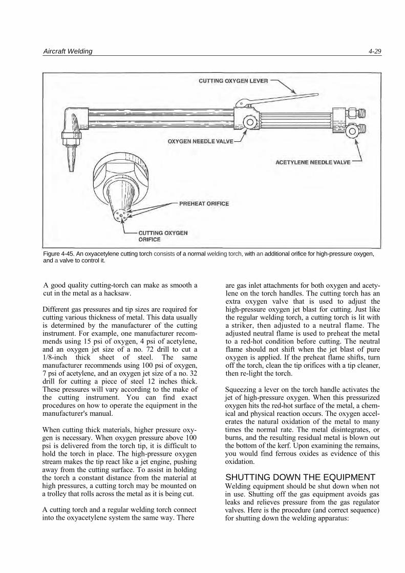
Aircraft Welding 4-29
Figure 4-45. An oxyacetylene cutting torch consists of a normal welding torch, with an additional orifice for high-pressure oxygen, and a valve to control it.
A good quality cutting-torch can make as smooth a cut in the metal as a hacksaw.
Different gas pressures and tip sizes are required for cutting various thickness of metal. This data usually is determined by the manufacturer of the cutting instrument. For example, one manufacturer recom-mends using 15 psi of oxygen, 4 psi of acetylene, and an oxygen jet size of a no. 72 drill to cut a 1/8-inch thick sheet of steel. The same manufacturer recommends using 100 psi of oxygen, 7 psi of acetylene, and an oxygen jet size of a no. 32 drill for cutting a piece of steel 12 inches thick. These pressures will vary according to the make of the cutting instrument. You can find exact procedures on how to operate the equipment in the manufacturer's manual.
When cutting thick materials, higher pressure oxy-gen is necessary. When oxygen pressure above 100 psi is delivered from the torch tip, it is difficult to hold the torch in place. The high-pressure oxygen stream makes the tip react like a jet engine, pushing away from the cutting surface. To assist in holding the torch a constant distance from the material at high pressures, a cutting torch may be mounted on a trolley that rolls across the metal as it is being cut.
A cutting torch and a regular welding torch connect into the oxyacetylene system the same way. There
are gas inlet attachments for both oxygen and acety-lene on the torch handles. The cutting torch has an extra oxygen valve that is used to adjust the high-pressure oxygen jet blast for cutting. Just like the regular welding torch, a cutting torch is lit with a striker, then adjusted to a neutral flame. The adjusted neutral flame is used to preheat the metal to a red-hot condition before cutting. The neutral flame should not shift when the jet blast of pure oxygen is applied. If the preheat flame shifts, turn off the torch, clean the tip orifices with a tip cleaner, then re-light the torch.
Squeezing a lever on the torch handle activates the jet of high-pressure oxygen. When this pressurized oxygen hits the red-hot surface of the metal, a chem-ical and physical reaction occurs. The oxygen accel-erates the natural oxidation of the metal to many times the normal rate. The metal disintegrates, or burns, and the resulting residual metal is blown out the bottom of the kerf. Upon examining the remains, you would find ferrous oxides as evidence of this oxidation.
SHUTTING DOWN THE EQUIPMENT Welding equipment should be shut down when not in use. Shutting off the gas equipment avoids gas leaks and relieves pressure from the gas regulator valves. Here is the procedure (and correct sequence) for shutting down the welding apparatus:
4-30 Aircraft Welding
1. Shut off the flame by closing the acetylene nee dle valve on the torch.
2. Close the oxygen needle valve on the torch.
3. Close the acetylene cylinder valve.
4. Close the oxygen cylinder valve.
5. Open the acetylene valve on the torch to drain the acetylene hose and regulator. This removes pressure on the regulator's working-pressure gauges.
6. Turn the acetylene-regulator adjusting screw to the left to relieve pressure on the diaphragm, and then close the torch acetylene valve.
7. Open the torch oxygen valve, drain the oxygen hose and regulator.
8. Turn the oxygen-regulator adjusting screw to the left to relieve the diaphragm pressure. Then close the torch oxygen valve.
9. Hang up the torch and hose properly to prevent hose or torch damage.