Embed Size (px)
DESCRIPTION
Chapter 36 Viewgraphs AC Circuits. Introduction. Most currents and voltages vary in time. The presence of circuit elements like capacitors and inductors complicates the relation between currents and voltage when these depend on time. Resistive element -I&V proportional. Reactive elements - PowerPoint PPT Presentation
Citation preview
Chapter 36 Viewgraphs
AC Circuits
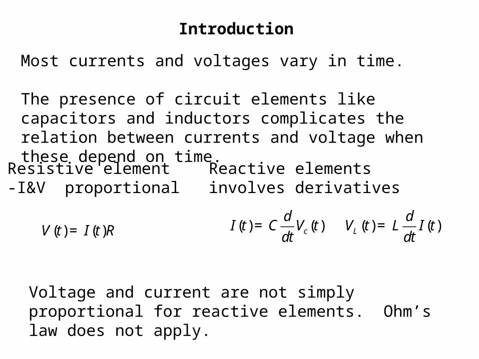
Most currents and voltages vary in time.
The presence of circuit elements like capacitors and inductors complicates the relation between currents and voltage when these depend on time.
V (t) = I(t)R I(t) = C
d
dtVc (t)
VL (t) = L
d
dtI(t)
Resistive element-I&V proportional
Reactive elementsinvolves derivatives
Voltage and current are not simply proportional for reactive elements. Ohm’s law does not apply.
Introduction
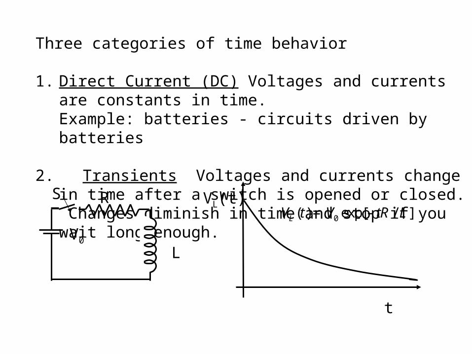
Three categories of time behavior
1. Direct Current (DC) Voltages and currents are constants in time.Example: batteries - circuits driven by batteries
2. Transients Voltages and currents change in time after a switch is opened or closed. Changes diminish in time and stop if you wait long enough.
S R
LV0
VL(t)
t
VL (t) = V0 exp[- tR / L]
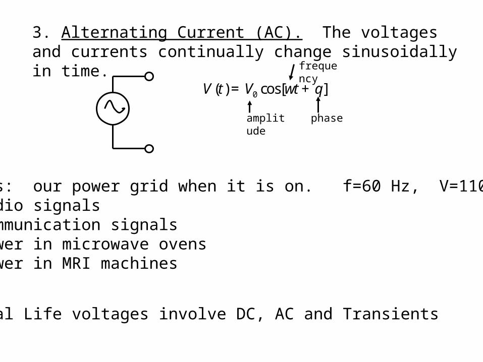
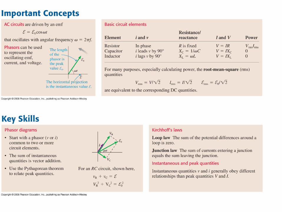
3. Alternating Current (AC). The voltages and currents continually change sinusoidally in time.
V (t) = V0 cos[wt + q]
amplitude
frequency
phase
Examples: our power grid when it is on. f=60 Hz, V=110 V (RMS)audio signalscommunication signalsPower in microwave ovensPower in MRI machines
Real Life voltages involve DC, AC and Transients
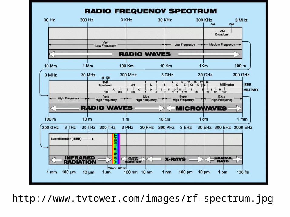
http://www.tvtower.com/images/rf-spectrum.jpg
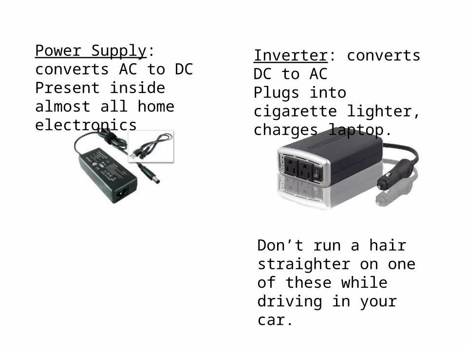
Power Supply: converts AC to DCPresent inside almost all home electronics
Inverter: converts DC to ACPlugs into cigarette lighter, charges laptop.
Don’t run a hair straighter on one of these while driving in your car.
AC - Circuits
First Rule of AC - Circuits - everything oscillates at the same frequency
If a circuit is driven by a source with frequency , and you wait for all transients to die out, the circuit will reach a state where every voltage and current is oscillating at the same frequency
Often this is called a “steady state” even though every thing is oscillating.
The problem then becomes: Find the amplitude and phase of each voltage and current.
Lc/pLc/mLc/m
Lc/n
Rc/pRc/mRc/m
Rc/n
Cc
Cs Ls
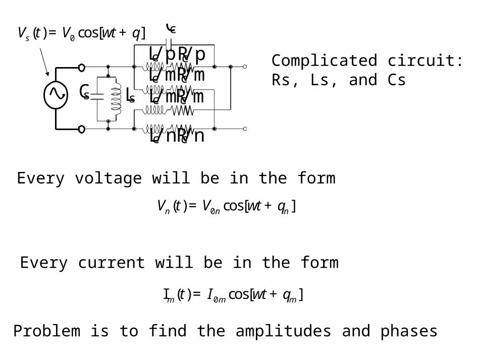
Vs (t) = V0 cos[wt + q]
Complicated circuit:Rs, Ls, and Cs
Every voltage will be in the form
Vn (t) = V0n cos[wt + qn ]
Every current will be in the form
Im (t) = I0m cos[wt + qm ]
Problem is to find the amplitudes and phases
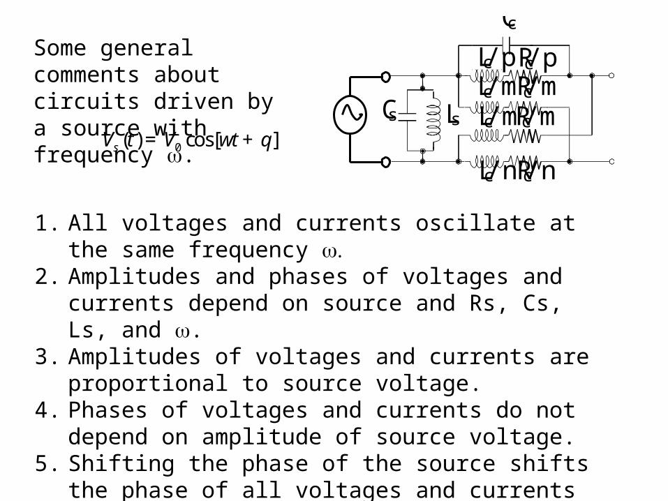
1. All voltages and currents oscillate at the same frequency 2. Amplitudes and phases of voltages and currents depend on
source and Rs, Cs, Ls, and .3. Amplitudes of voltages and currents are proportional to
source voltage.4. Phases of voltages and currents do not depend on
amplitude of source voltage.5. Shifting the phase of the source shifts the phase of all
voltages and currents by the same amount.
Lc/pLc/mLc/m
Lc/n
Rc/pRc/mRc/m
Rc/n
Cc
Cs Ls
Some general comments about circuits driven by a source with frequency .
Vs (t) = V0 cos[wt + q]
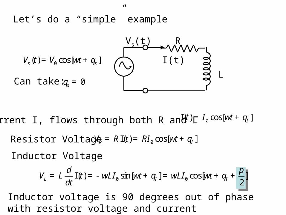
Let’s do a “simple” example
R
L
Vs(t)
I(t) Vs (t) = V0 cos[wt + qs ]
qs = 0Can take:
Resistor Voltage
Current I, flows through both R and L I(t) = I0 cos[wt + qI ]
VR = R I(t) = RI0 cos[wt + qI ]
Inductor Voltage
VL = L
d
dtI(t) = - wLI0 sin[wt + qI ] = wLI0 cos[wt + qI +
p
2]
Inductor voltage is 90 degrees out of phase with resistor voltage and current
VL(t)
I(t)
t
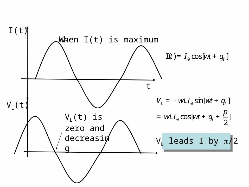
I(t) = I0 cos[wt + qI ]
VL = - wLI0 sin[wt + qI ]
= wLI0 cos[wt + qI +p
2]
When I(t) is maximum
VL(t) is zero and decreasing VL leads I by /2
-3
-2
-1
0
1
2
3
0 2 4 6 8 10 12 14
BC
Voltage or Current
time
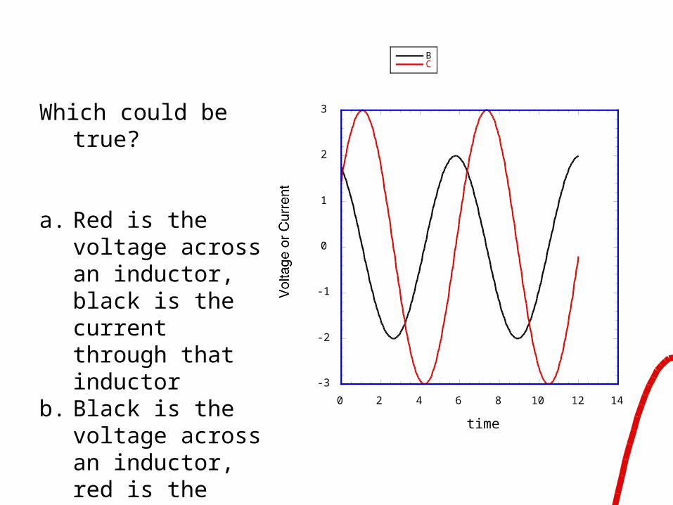
Which could be true?
a. Red is the voltage across an inductor, black is the current through that inductor
b. Black is the voltage across an inductor, red is the current through that inductor
c. neither of the above
-3
-2
-1
0
1
2
3
0 2 4 6 8 10 12 14
BC
Voltage or Current
time
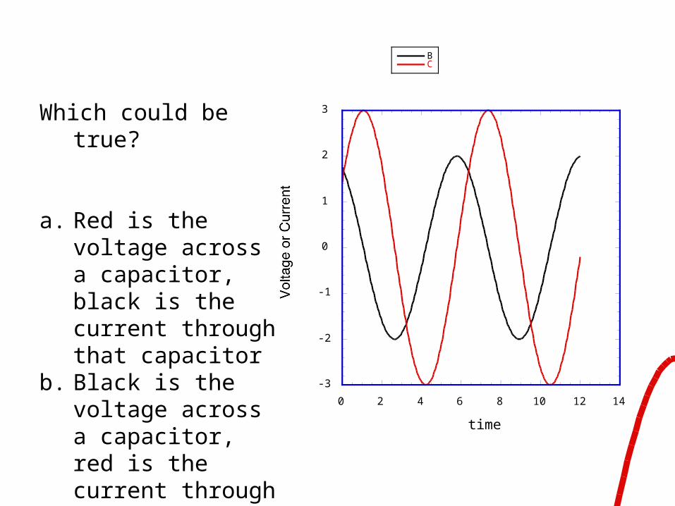
Which could be true?
a. Red is the voltage across a capacitor, black is the current through that capacitor
b. Black is the voltage across a capacitor, red is the current through that capacitor
c. neither of the above

Let’s do a “simple” example
R
L
Vs(t)
I(t) Vs (t) = V0 cos[wt + qs ]
qs = 0Can take:
Resistor Voltage
Current I, flows through both R and L I(t) = I0 cos[wt + qI ]
VR = R I(t) = RI0 cos[wt + qI ]
Inductor Voltage
VL = L
d
dtI(t) = - wLI0 sin[wt + qI ] = wLI0 cos[wt + qI +
p
2]
Inductor voltage is 90 degrees out of phase with resistor voltage and current

VL(t)
I(t)
t
I(t) = I0 cos[wt + qI ]
VL = - wLI0 sin[wt + qI ]
= wLI0 cos[wt + qI +p
2]
When I(t) is maximum
VL(t) is zero and decreasing VL leads I by /2
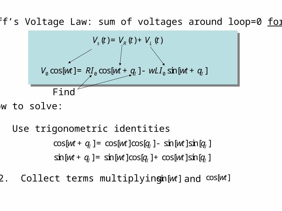
Kirchoff’s Voltage Law: sum of voltages around loop=0 for all t
Vs (t) = VR (t) + VL (t)
V0 cos[wt] = RI0 cos[wt + qI ]- wLI0 sin[wt + qI ]
Find
cos[wt + qI ] = cos[wt]cos[qI ]- sin[wt]sin[qI ]
How to solve:
1. Use trigonometric identities
sin[wt + qI ] = sin[wt]cos[qI ]+ cos[wt]sin[qI ]
2. Collect terms multiplying sin[wt] cos[wt]and
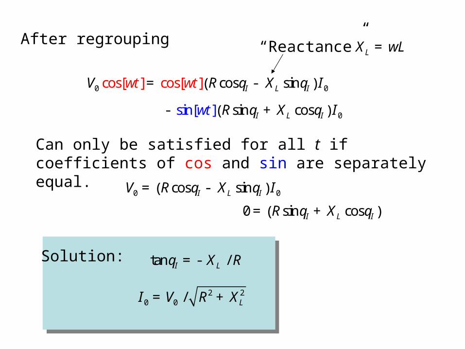
V0 cos[wt] = cos[wt] RcosqI - XL sinqI( ) I0
- sin[wt] RsinqI + XL cosqI( ) I0
After regrouping XL = wL“Reactance”
V0 = RcosqI - XL sinqI( ) I0
0 = RsinqI + XL cosqI( )
Solution: tanqI = - XL / R
I0 = V0 / R2 + XL2
Can only be satisfied for all t if coefficients of cos and sin are separately equal.
VR = V0
R
R2 + XL2
cos[wt + qI ]
VL = V0
XL
R2 + XL2
cos[wt + qI +p
2]
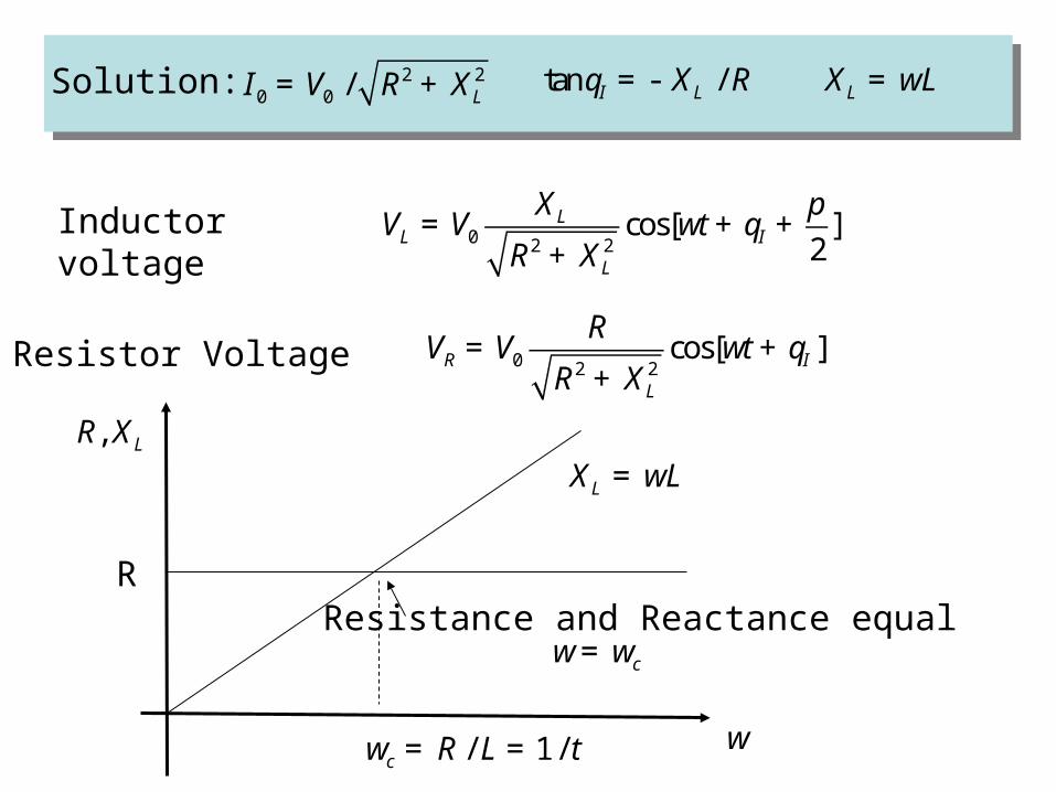
Solution: tanqI = - XL / R I0 = V0 / R2 + XL
2 XL = wL
Inductor voltage
Resistor Voltage
R, XL
w
XL = wL
R
wc = R / L = 1 / t
Resistance and Reactance equal w= wc
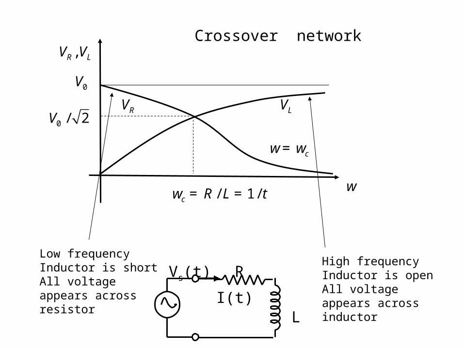
VR , VL
w wc = R / L = 1 / t
w= wc
VL
V0
Crossover network
VRV0 / 2
R
L
Vs(t)
I(t)
Low frequencyInductor is shortAll voltage appears across resistor
High frequencyInductor is openAll voltage appears across inductor
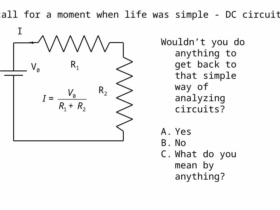
Recall for a moment when life was simple - DC circuits.
R1
R2
V0
I
I =
V0
R1 + R2
Wouldn’t you do anything to get back to that simple way of analyzing circuits?
A. YesB. NoC. What do you mean
by anything?
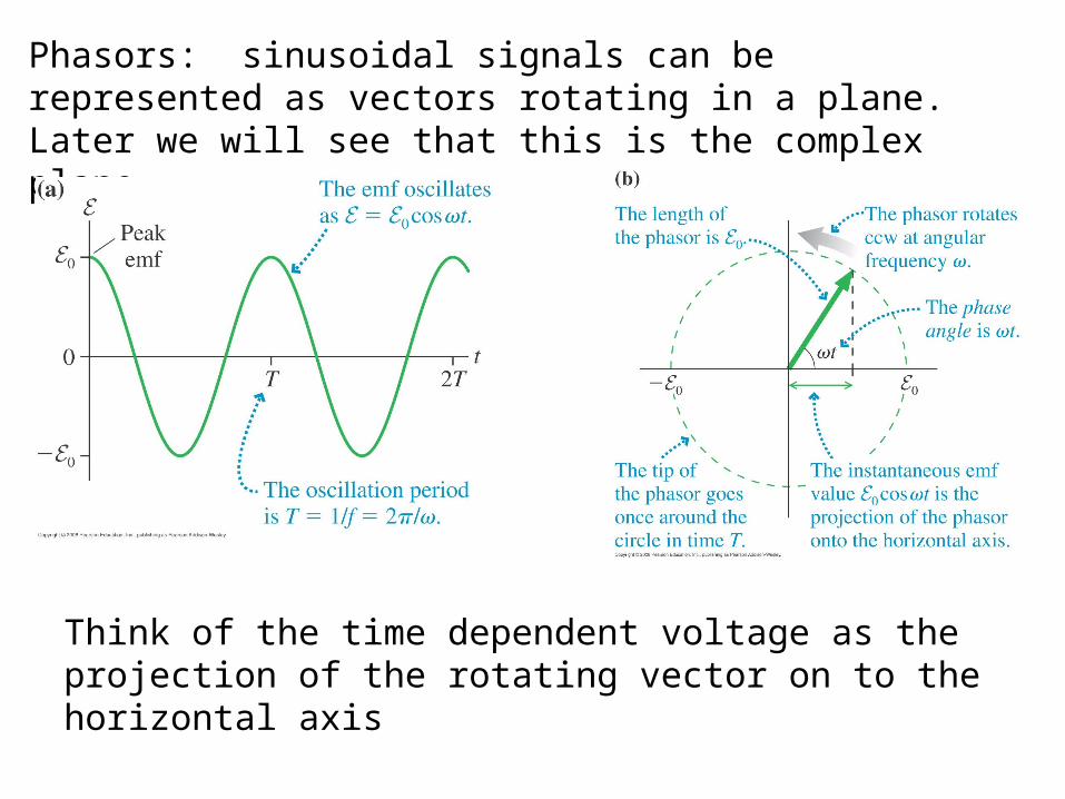
Phasors: sinusoidal signals can be represented as vectors rotating in a plane. Later we will see that this is the complex plane
Think of the time dependent voltage as the projection of the rotating vector on to the horizontal axis
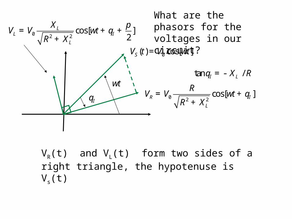
What are the phasors for the voltages in our circuit?
VS (t) = V0 cos[wt]
VR = V0
R
R2 + XL2
cos[wt + qI ]
tanqI = - XL / R
VL = V0
XL
R2 + XL2
cos[wt + qI +p
2]
qI
wt
VR(t) and VL(t) form two sides of a right triangle, the hypotenuse is Vs(t)
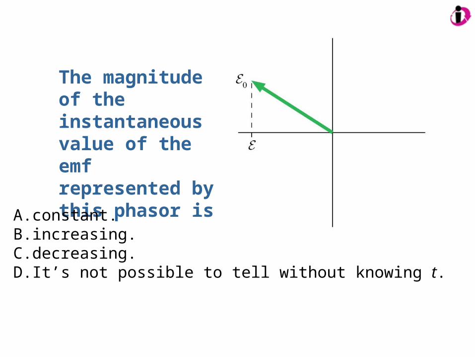
The magnitude of the instantaneous value of the emf represented by this phasor is
A. constant.B. increasing.C. decreasing.D. It’s not possible to tell without knowing t.
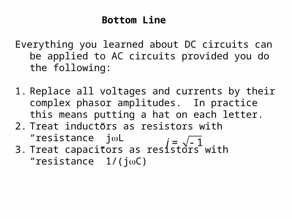
Bottom Line
Everything you learned about DC circuits can be applied to AC circuits provided you do the following:
1. Replace all voltages and currents by their complex phasor amplitudes. In practice this means putting a hat on each letter.
2. Treat inductors as resistors with “resistance” jL3. Treat capacitors as resistors with “resistance” 1/(jC)
j = - 1
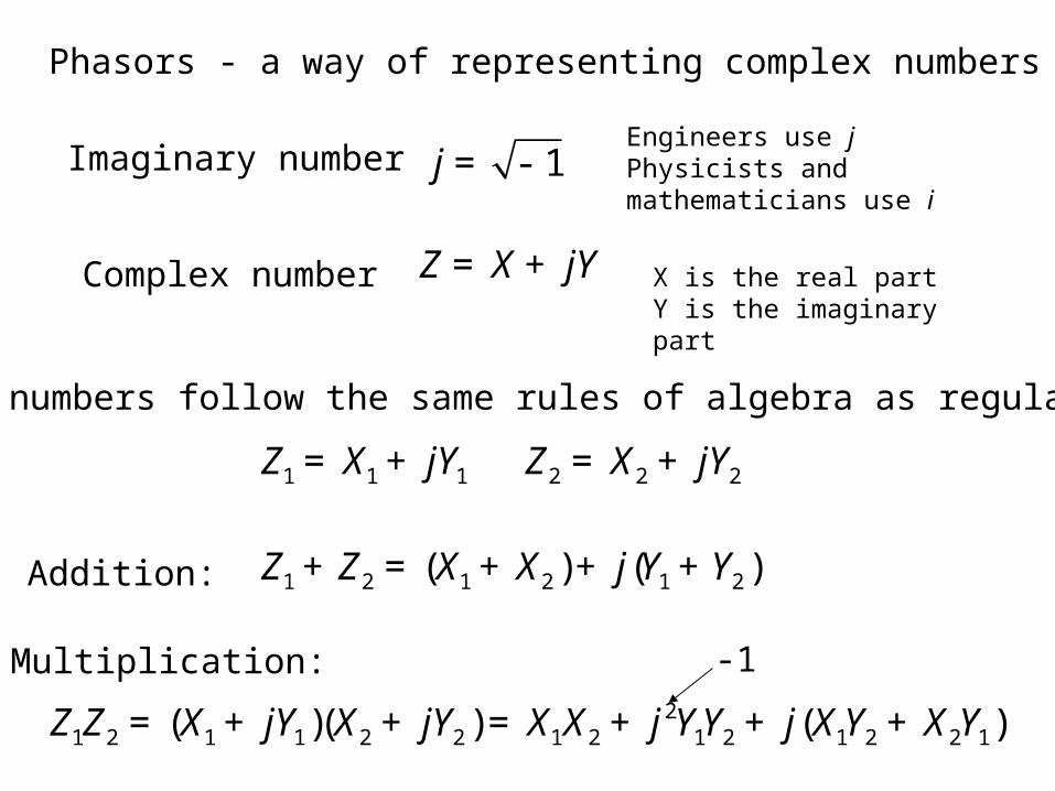
Phasors - a way of representing complex numbers
Imaginary number j = - 1Engineers use jPhysicists and mathematicians use i
Complex number Z = X + jY X is the real partY is the imaginary part
Complex numbers follow the same rules of algebra as regular numbers
Z1 = X1 + jY1 Z2 = X2 + jY2
Z1 + Z2 = (X1 + X2 ) + j(Y1 + Y2 )Addition:
Multiplication:
Z1Z2 = (X1 + jY1)(X2 + jY2 ) = X1X2 + j2Y1Y2 + j(X1Y2 + X2Y1)
-1
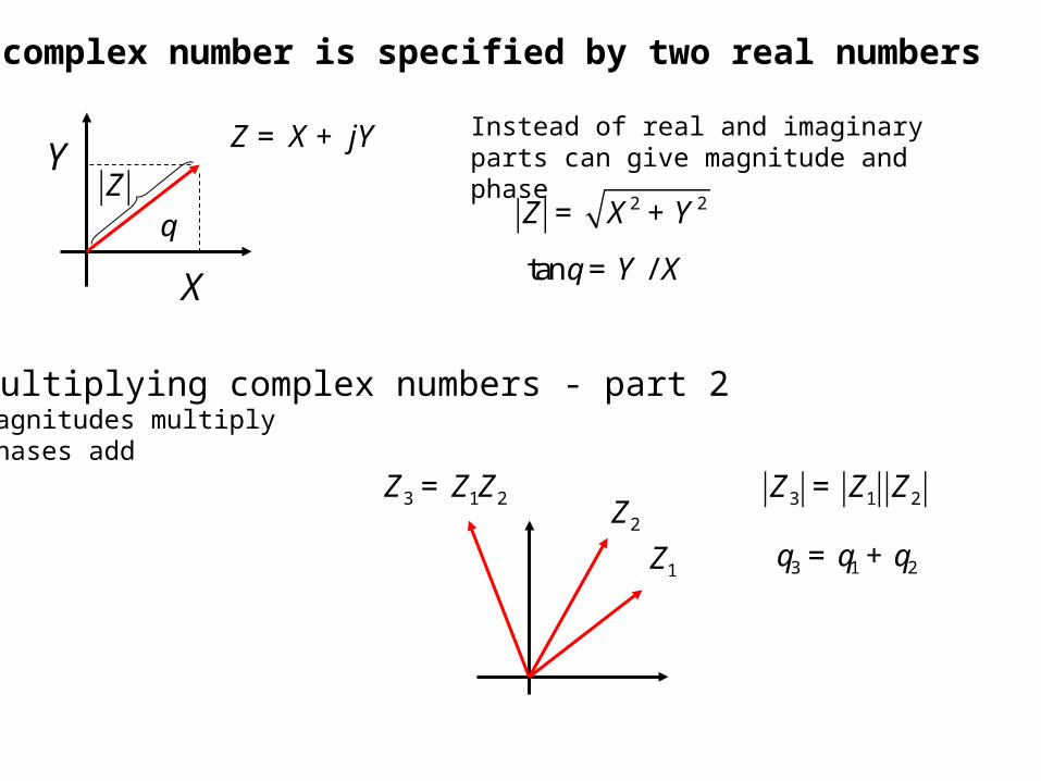
A complex number is specified by two real numbers
Z = X + jY
X
YZ
q
Instead of real and imaginary parts can give magnitude and phase
Z = X 2 + Y 2
tanq = Y / X
Multiplying complex numbers - part 2Magnitudes multiplyPhases add
Z1 q3 = q1 + q2
Z2 Z3 = Z1Z2 Z3 = Z1 Z2
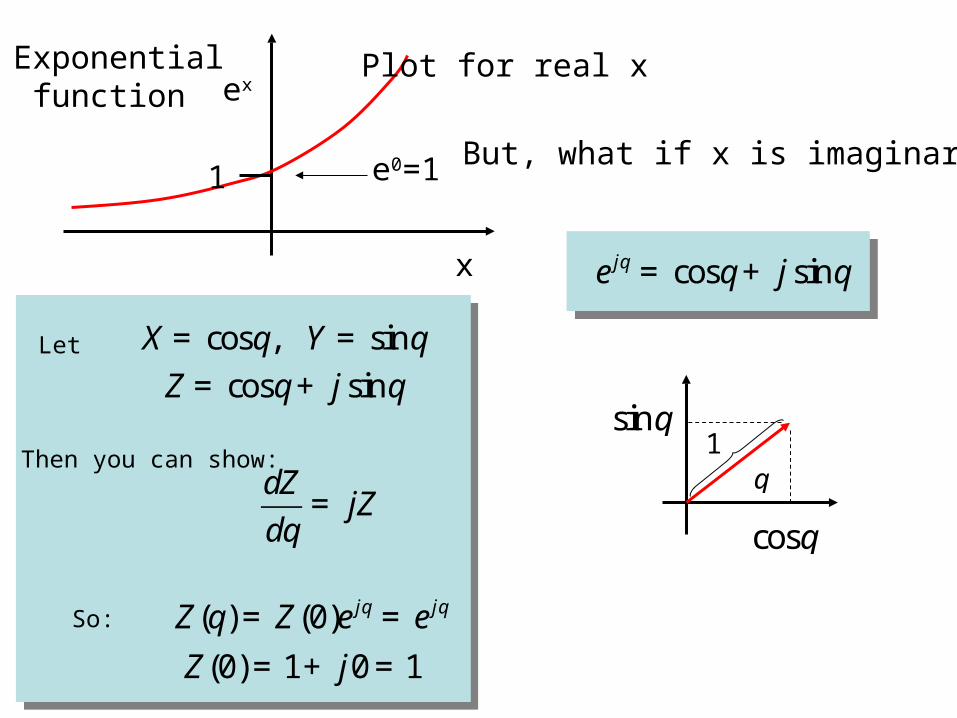
Exponential function ex
x
1 e0=1 But, what if x is imaginary?
Plot for real x
ejq = cosq+ j sinq
cosq
sinq1
q
Let X = cosq, Y = sinq
Z = cosq+ j sinq
Then you can show:
dZ
dq= jZ
So: Z(q) = Z(0)e jq = e jq
Z(0) = 1+ j0 = 1
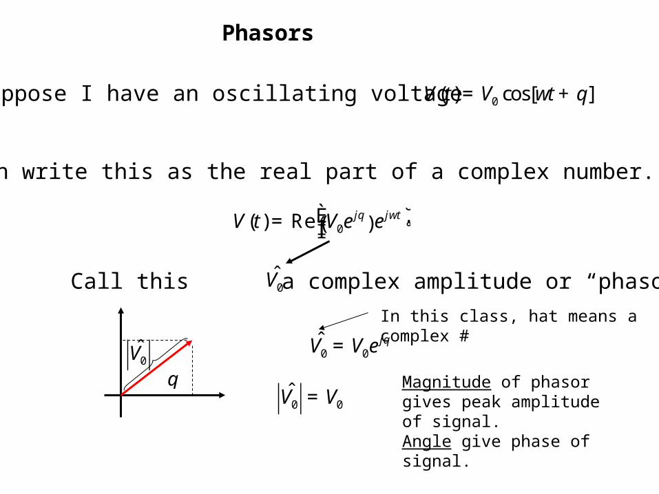
Phasors
Suppose I have an oscillating voltage V (t) = V0 cos[wt + q]
I can write this as the real part of a complex number.
V (t) = Re V0e
jq( )e jwtÈÎÍ
˘˚
Call this a complex amplitude or “phasor” V0
V0
q V0 = V0e
jq
In this class, hat means a complex #
V0 = V0
Magnitude of phasor gives peak amplitude of signal.Angle give phase of signal.
V0
q
V0ejwt
wt
V0 cos(wt + q)
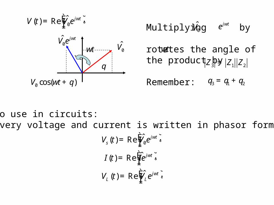
Multiplying by rotates the angle of the product by
Remember:
V0 ejwt
wt
q3 = q1 + q2
Z3 = Z1 Z2
How to use in circuits:1. Every voltage and current is written in phasor form:
Vs (t) = Re V0e
jwtÈÎÍ
˘˚
I(t) = Re Ie jwtÈ
Î͢˚
VL (t) = Re VLe
jwtÈÎÍ
˘˚
V (t) = Re V0e
jwtÈÎÍ
˘˚
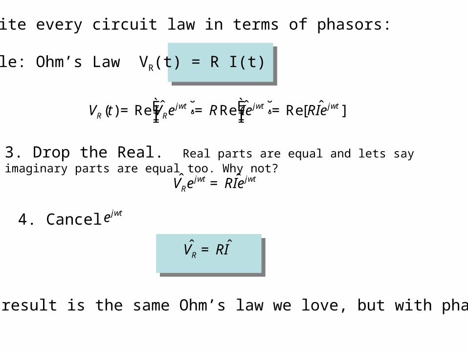
2. Write every circuit law in terms of phasors:
Example: Ohm’s Law VR(t) = R I(t)
VR (t) = Re VRe
jwtÈÎÍ
˘˚= RRe Ie jwtÈ
Î͢˚= Re[RIe jwt ]
3. Drop the Real. Real parts are equal and lets say imaginary parts are equal too. Why not?
VRejwt = RIe jwt
4. Cancel ejwt
VR = RI
5. The result is the same Ohm’s law we love, but with phasors!
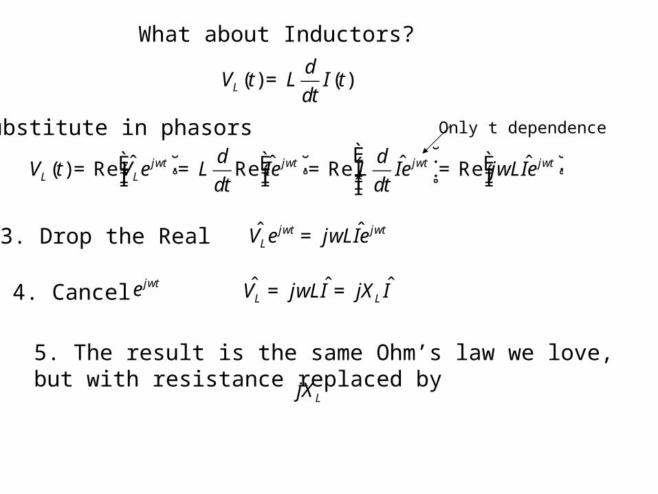
What about Inductors?
VL (t) = Re VLe
jwtÈÎÍ
˘˚= L
d
dtRe Ie jwtÈ
Î͢˚= Re L
d
dtIe jwtÈ
ÎÍÍ
˘
˚˙˙= Re jwLIe jwtÈ
Î͢˚
VL (t) = L
d
dtI(t)
Substitute in phasors Only t dependence
3. Drop the Real VLejwt = jwLIe jwt
4. Cancel ejwt
VL = jwLI = jXL I
5. The result is the same Ohm’s law we love, but with resistance replaced by jXL
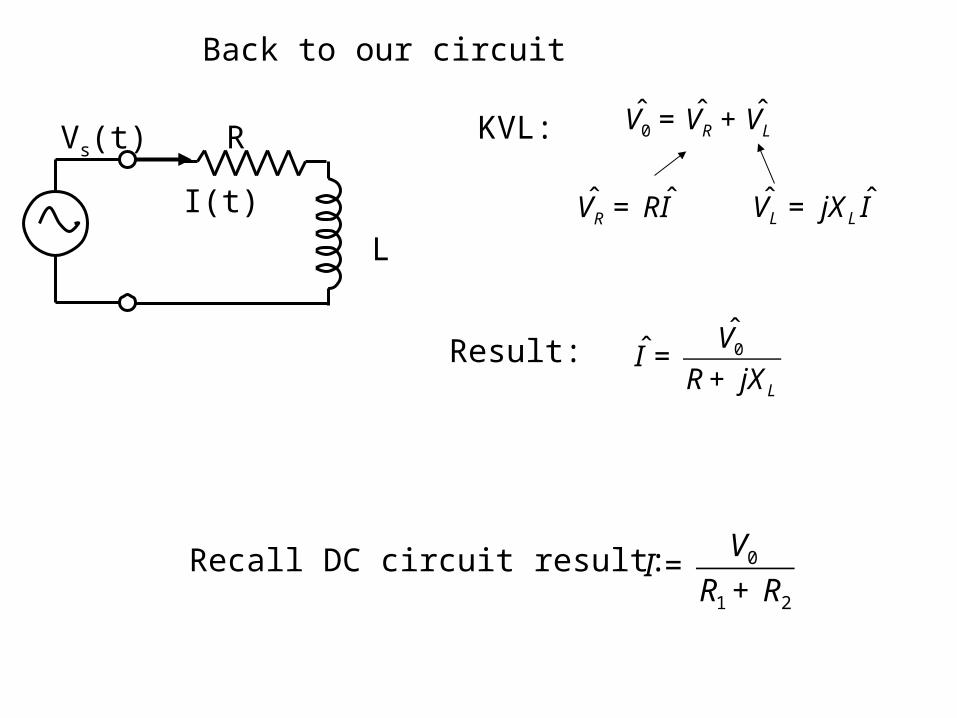
Back to our circuit
R
L
Vs(t)
I(t)
KVL: V0 = VR + VL
VL = jXL I VR = RI
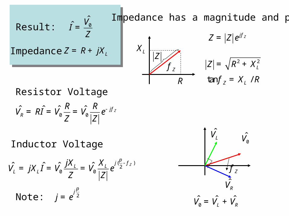
Result: I =
V0
R+ jXL
Recall DC circuit result:
I =
V0
R1 + R2
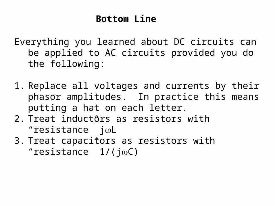
Bottom Line
Everything you learned about DC circuits can be applied to AC circuits provided you do the following:
1. Replace all voltages and currents by their phasor amplitudes. In practice this means putting a hat on each letter.
2. Treat inductors as resistors with “resistance” jL3. Treat capacitors as resistors with “resistance” 1/(jC)
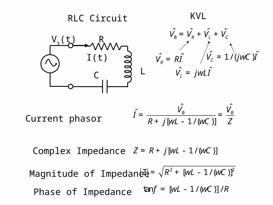
RLC Circuit
R
L
Vs(t)
I(t)
C
V0 = VR + VL + VC
VL = jwLI VR = RI VC = 1 / ( jwC)I
KVL
Current phasor I =
V0
R+ j[wL - 1 / (wC)]=
V0
Z
Complex Impedance Z = R + j[wL - 1 / (wC)]
Magnitude of Impedance Z = R2 + [wL - 1 / (wC)]2
Phase of Impedance tan f = [wL - 1 / (wC)] / R
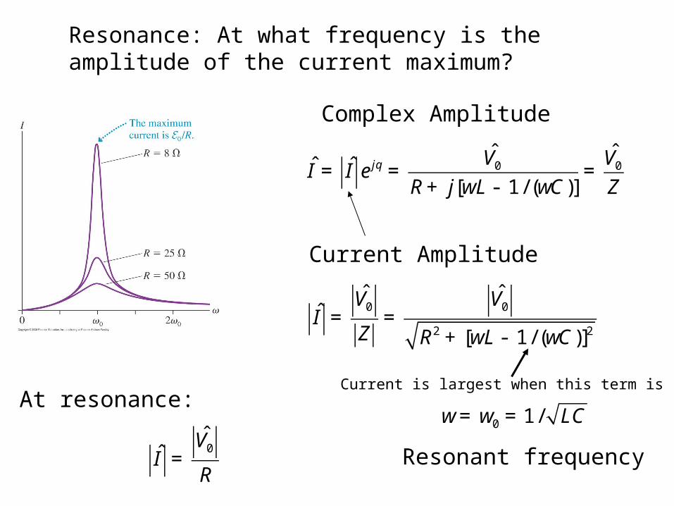
Resonance: At what frequency is the amplitude of the current maximum?
I = I e jq =
V0
R+ j[wL - 1 / (wC)]=
V0
Z
Complex Amplitude
I =
V0
Z=
V0
R2 + [wL - 1 / (wC)]2
Current Amplitude
Current is largest when this term is zero
w= w0 = 1 / LC
Resonant frequency
At resonance:
I =
V0
R
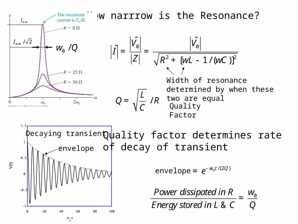
How narrrow is the Resonance?
I =
V0
Z=
V0
R2 + [wL - 1 / (wC)]2
Imax
Imax / 2
w0 /Q
Q =
L
C/ R
Quality Factor
Width of resonance determined by when these two are equal
-1
-0.5
0
0.5
1
1.5
0 20 40 60 80 100
0t
envelope
Decaying transient Quality factor determines rate of decay of transient
envelope = e- wot /(2Q )
Power dissipated in R
Energy stored in L & C=
w0
Q
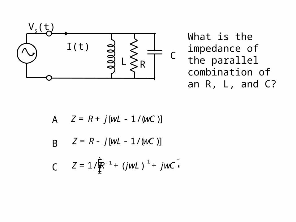
RL
Vs(t)
I(t)C
What is the impedance of the parallel combination of an R, L, and C?
Z = R + j[wL - 1 / (wC)]
Z = R - j[wL - 1 / (wC)]
Z = 1 / R- 1 + jwL( )
- 1+ jwCÈ
Î͢˚
A
B
C
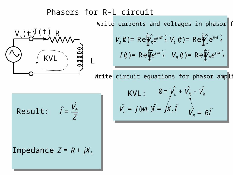
Phasors for R-L circuit
L
Result: I =
V0
Z
Impedance Z = R + jXL
RVs(t) I(t)
KVL
Vs (t) = Re V0e
jwtÈÎÍ
˘˚
I (t) = Re Ie jwtÈ
Î͢˚
VL (t) = Re VLe
jwtÈÎÍ
˘˚
VR (t) = Re VRe
jwtÈÎÍ
˘˚
Write currents and voltages in phasor form
KVL: 0 = VL + VR - V0
VL = j(wL)I = jXL I VR = RI
Write circuit equations for phasor amplitudes
Result: I =
V0
Z
Impedance Z = R + jXL
Impedance has a magnitude and phase
Z = Z e jf Z
Z = R2 + XL2
tan f Z = XL / R
Z
f Z
R
XL
Resistor Voltage
VL = jXL I = V0
jXL
Z= V0
XL
Ze
j (p
2- f Z )
VR = RI = V0
R
Z= V0
R
Ze- jf Z
Inductor VoltageV0
f Z
VR
VL
V0 = VL + VR j = e
jp
2Note:
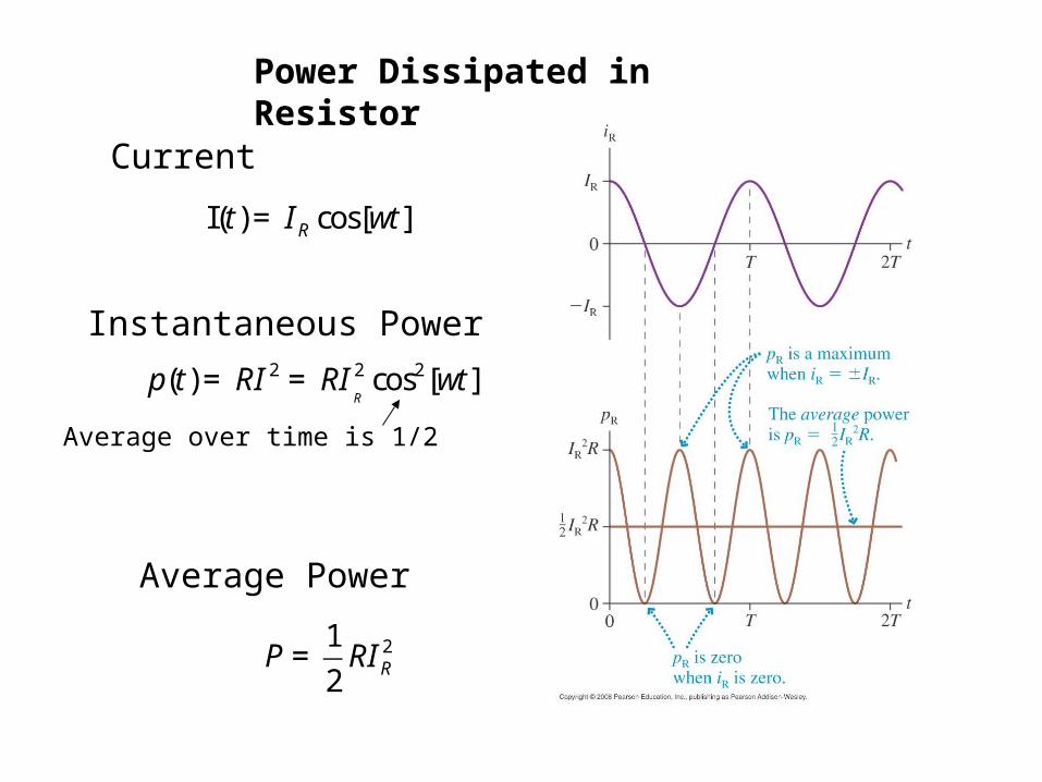
Power Dissipated in Resistor
I(t) = IR cos[wt]
p(t) = RI 2 = RI
R
2 cos2[wt]
Current
Instantaneous Power
Average over time is 1/2
P =
1
2RIR
2
Average Power
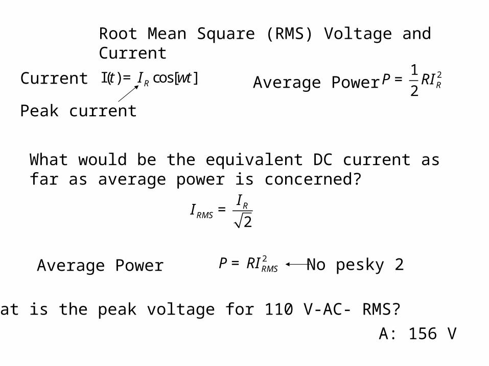
Root Mean Square (RMS) Voltage and Current
I(t) = IR cos[wt]Current P =
1
2RIR
2Average Power
Peak current
What would be the equivalent DC current as far as average power is concerned?
IRMS =
IR
2
P = RIRMS2
Average Power
What is the peak voltage for 110 V-AC- RMS?
A: 156 V
No pesky 2
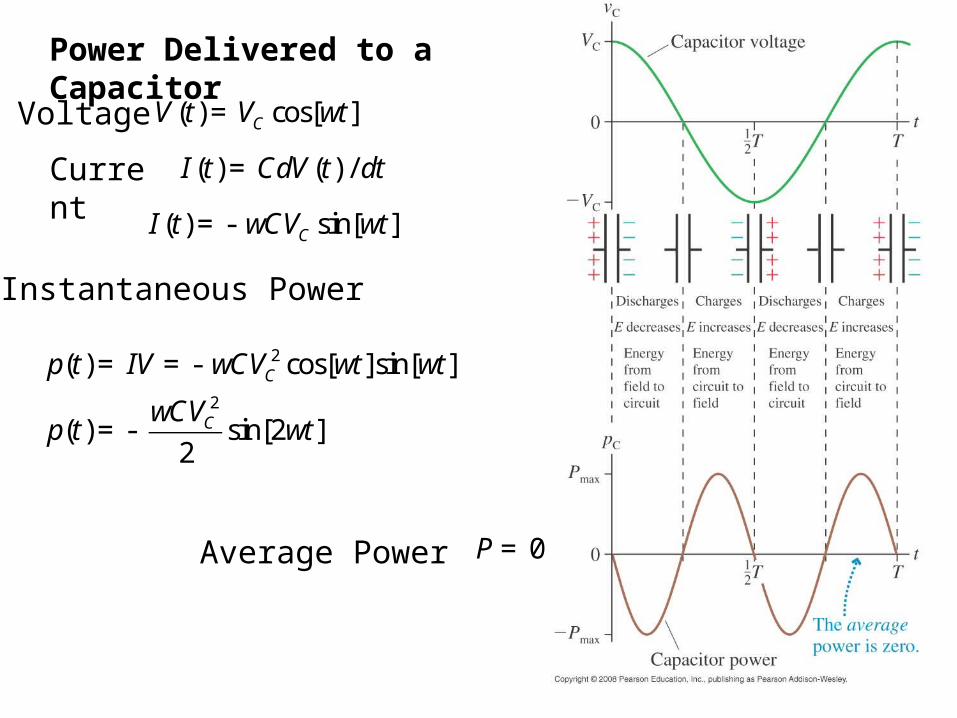
Power Delivered to a Capacitor
V (t) = VC cos[wt]
p(t) = IV = - wCVC2 cos[wt]sin[wt]
p(t) = -wCVC
2
2sin[2wt]
Current
Instantaneous Power
P = 0Average Power
Voltage
I (t) = CdV (t) / dt
I (t) = - wCVC sin[wt]
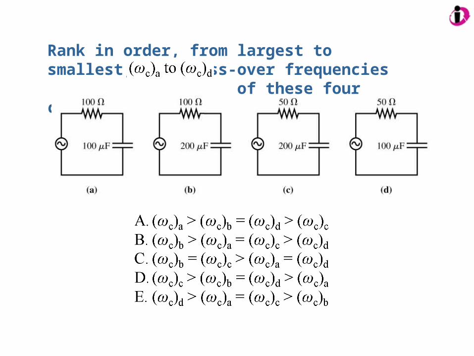
Rank in order, from largest to smallest, the cross-over frequencies of these four circuits.
A series RLC circuit has VC = 5.0 V, VR = 7.0 V, and VL = 9.0 V. Is the frequency above, below or equal to the resonance frequency?
A. Above the resonance frequencyB. Below the resonance frequencyC. Equal to the resonance frequency
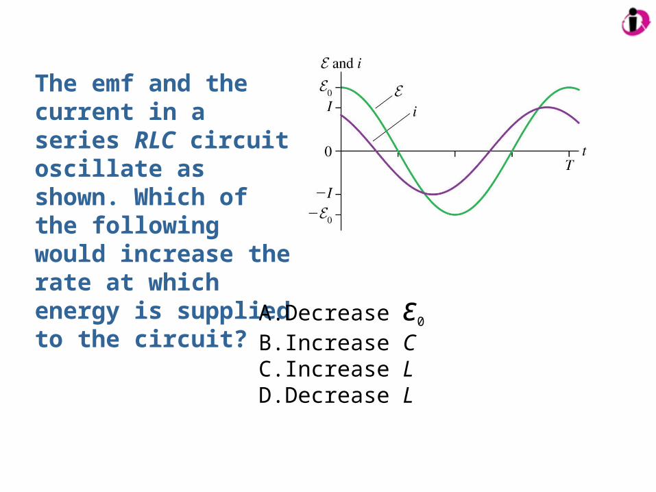
The emf and the current in a series RLC circuit oscillate as shown. Which of the following would increase the rate at which energy is supplied to the circuit?
A. Decrease ε0
B. Increase CC. Increase LD. Decrease L