Embed Size (px)
Citation preview

SOLIDWORKS 16 HyDRO HuLL BOAT PAge 30-1
Boat
Hydro Hull A. Save as "HYDRO".Step 1. Open your HULL MID PLANE file (Chapter 2).
Step 2. Click File Menu > Save As.
Step 3. Key-in HYDRO for the filename and press ENTER.
B. Delete Loft1, Sketch2 and Sketch3.Step 1. Click Loft1 in the Feature Manager, Fig. 1.
Step 2. Press Delete key on keyboard and Yes to con-firm delete.
Step 3. Repeat and delete Sketch2 and Sketch3, Ctrl click Sketch2 and Sketch3 in the Feature Man-ager, press Delete key on keyboard and Yes to confirm delete, Fig. 2.
C. Change Mid Plane.Step 1. Click Mid Plane in the Feature Manager
and click Edit Feature on the context toolbar, Fig. 3.
Step 2. In the Plane Property Manager set: under First Reference, Fig. 4
Distance 4.7 click OK .
Step 3. Show Rear Plane and Mid Plane . To show Planes, Ctrl click each Plane to select
both and click Show on the con-text toolbar, Fig. 5 and Fig. 6.
Chapter 30
2/17/16
Fig. 2Fig. 1Delete Delete
Fig. 4
Fig. 3
Fig. 5Fig. 6
© Cudacountry.net Tech Edhttp://www.cudacountry.net email:[email protected]
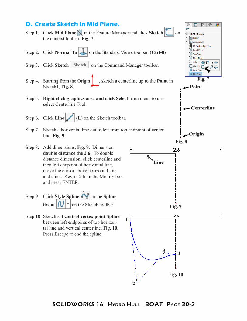
SOLIDWORKS 16 HyDRO HuLL BOAT PAge 30-2
D. Create Sketch in Mid Plane.Step 1. Click Mid Plane in the Feature Manager and click Sketch on
the context toolbar, Fig. 7.
Step 2. Click Normal To on the Standard Views toolbar. (Ctrl-8)
Step 3. Click Sketch on the Command Manager toolbar.
Step 4. Starting from the Origin , sketch a centerline up to the Point in Sketch1, Fig. 8.
Step 5. Right click graphics area and click Select from menu to un-select Centerline Tool.
Step 6. Click Line (L) on the Sketch toolbar.
Step 7. Sketch a horizontal line out to left from top endpoint of center-line, Fig. 9.
Step 8. Add dimensions, Fig. 9. Dimension double distance the 2.6. To double distance dimension, click centerline and then left endpoint of horizontal line, move the cursor above horizontal line and click. Key-in 2.6 in the Modify box and press ENTER.
Step 9. Click Style Spline in the Spline
flyout on the Sketch toolbar.
Step 10. Sketch a 4 control vertex point Spline between left endpoints of top horizon-tal line and vertical centerline, Fig. 10. Press Escape to end the spline.
Fig. 7
Fig. 9
Fig. 8Origin
Point
Centerline
Fig. 10
Line
2
3
1
4

SOLIDWORKS 16 HyDRO HuLL BOAT PAge 30-3
Step 11. Click bottom control polygon segment
and click Make Horizontal on the context toolbar, Fig. 11.
Step 12. Click Smart Dimension (S) on the Sketch toolbar.
Step 13. Add dimensions, Fig. 12.
Step 14. Right click graphics area and click Select from menu to unselect Smart Dimension.
Step 15. Drag a selection to select all entities, Fig. 13.
Step 16. Click Mirror Entities on the Sketch toolbar, Fig. 14.
Step 17. Click Exit Sketch on the Sketch toolbar.
Step 18. Save. Use Ctrl-S.
Fig. 11
Fig. 12
Fig. 14Fig. 13
Drag selection to right
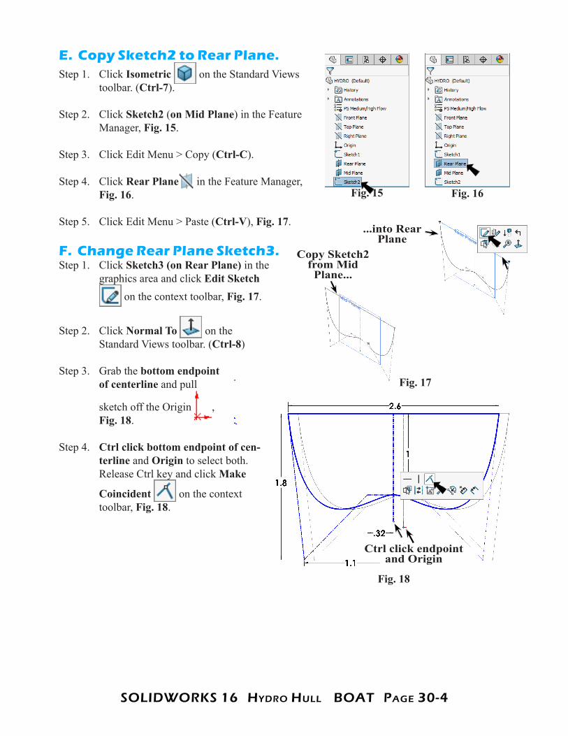
SOLIDWORKS 16 HyDRO HuLL BOAT PAge 30-4
E. Copy Sketch2 to Rear Plane.Step 1. Click Isometric on the Standard Views
toolbar. (Ctrl-7).
Step 2. Click Sketch2 (on Mid Plane) in the Feature Manager, Fig. 15.
Step 3. Click Edit Menu > Copy (Ctrl-C).
Step 4. Click Rear Plane in the Feature Manager, Fig. 16.
Step 5. Click Edit Menu > Paste (Ctrl-V), Fig. 17.
F. Change Rear Plane Sketch3.Step 1. Click Sketch3 (on Rear Plane) in the
graphics area and click Edit Sketch on the context toolbar, Fig. 17.
Step 2. Click Normal To on the Standard Views toolbar. (Ctrl-8)
Step 3. Grab the bottom endpoint of centerline and pull
sketch off the Origin , Fig. 18.
Step 4. Ctrl click bottom endpoint of cen-terline and Origin to select both. Release Ctrl key and click Make
Coincident on the context toolbar, Fig. 18.
Fig. 16Fig. 15
Fig. 17
Copy Sketch2 from Mid Plane...
...into Rear Plane
Fig. 18
Ctrl click endpoint and Origin
SOLIDWORKS 16 HyDRO HuLL BOAT PAge 30-5
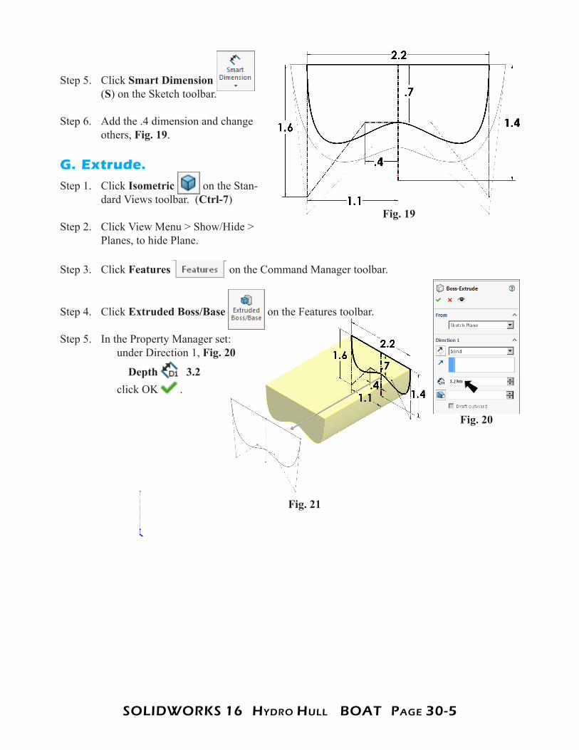
Step 5. Click Smart Dimension (S) on the Sketch toolbar.
Step 6. Add the .4 dimension and change others, Fig. 19.
G. Extrude.Step 1. Click Isometric on the Stan-
dard Views toolbar. (Ctrl-7)
Step 2. Click View Menu > Show/Hide > Planes, to hide Plane.
Step 3. Click Features on the Command Manager toolbar.
Step 4. Click Extruded Boss/Base on the Features toolbar.
Step 5. In the Property Manager set: under Direction 1, Fig. 20
Depth 3.2 click OK .
Fig. 19
Fig. 20
Fig. 21

SOLIDWORKS 16 HyDRO HuLL BOAT PAge 30-6
H. Loft Boss/Base.Step 1. Click Lofted Boss/Base on the Features toolbar.
Step 2. In the Loft Property Manager: under Profiles, Fig. 22 click Point1 Sketch1, Fig. 23 Sketch2 Face of extrude if necessary, reposition connector points of profiles to align loft expand Start/End Constraints Start constraint: Normal to Profile Start Tangent Length 1.5 End constraint: Normal to Profile End Tangent Length 1 click OK .
Step 3. Save. Use Ctrl-S.
Fig. 22Fig. 23
Fig. 24
Connector point
SOLIDWORKS 16 HyDRO HuLL BOAT PAge 30-7
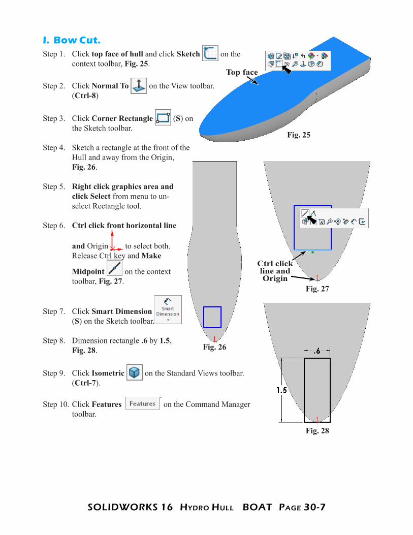
I. Bow Cut.Step 1. Click top face of hull and click Sketch on the
context toolbar, Fig. 25.
Step 2. Click Normal To on the View toolbar. (Ctrl-8)
Step 3. Click Corner Rectangle (S) on the Sketch toolbar.
Step 4. Sketch a rectangle at the front of the Hull and away from the Origin, Fig. 26.
Step 5. Right click graphics area and click Select from menu to un-select Rectangle tool.
Step 6. Ctrl click front horizontal line
and Origin to select both. Release Ctrl key and Make
Midpoint on the context toolbar, Fig. 27.
Step 7. Click Smart Dimension (S) on the Sketch toolbar.
Step 8. Dimension rectangle .6 by 1.5, Fig. 28.
Step 9. Click Isometric on the Standard Views toolbar. (Ctrl-7).
Step 10. Click Features on the Command Manager toolbar.
Fig. 25
Top face
Fig. 26
Fig. 28
Fig. 27
Ctrl click line and Origin

SOLIDWORKS 16 HyDRO HuLL BOAT PAge 30-8
Step 11. Click Extruded Cut on the Features toolbar.
Step 12. In the Cut-Extrude Property Manager set: under Direction 1, Fig. 29 End Condition Through All
click Draft On 6º check Draft outward. The Direction arrow should point towards area to be cut away, Fig. 30. If arrow is pointing in wrong direction, click Flip side to cut.Click OK .
J. Draft Bow Extrude Cut.Step 1. Click Draft on the Features
toolbar.
Step 2. In the Draft Property Manager set: under Type of Draft, Fig. 31 select Neutral Plane under Draft Angle 60º under Neutral Plane click top face of hull, Fig. 32 under Faces to Draft click front face of extruded cut under Neutral Plane
click Reverse Direction Direction arrow points down click OK .
Step 3. Rotate view to view draft from bottom, Fig. 33. Hold down middle mouse button (wheel) and drag.
Step 4. Save. Use Ctrl-S.
Fig. 29
Fig. 30
Direction arrow
Fig. 31Fig. 32
Neutral Plane
Draft face
Direction arrow
Fig. 33

SOLIDWORKS 16 HyDRO HuLL BOAT PAge 30-9
K. Stern Cut.Step 1. Click Top on the Standard Views toolbar.
(Ctrl-5)
Step 2. Click top face of hull and click Sketch on the context toolbar, Fig. 34.
Step 3. Click Corner Rectangle (S) on the Sketch toolbar.
Step 4. Sketch a rectangle over the rear Hull and away from rear edge, Fig. 35.
Step 5. Right click graphics area and click Select from menu to unselect Rectangle tool.
Step 6. Ctrl click midpoint of rear hull edge and rear horizontal line of rectangle to select both. Release Ctrl key
and click Make Midpoint on the context toolbar, Fig. 36.
Step 7. Click Smart Dimension
(S) on the Sketch toolbar.
Step 8. Dimension rectangle .6 by 1, Fig. 37.
Step 9. Rotate view to view rear of Hull, Fig. 38. Hold down middle mouse button (wheel) and drag.
Step 10. Click Features on the
Command Manager toolbar.
Fig. 34
Top face
Fig. 35
Fig. 36 Fig. 37
Ctrl click midpoint and
line
Fig. 38

SOLIDWORKS 16 HyDRO HuLL BOAT PAge 30-10
Step 11. Click Extruded Cut on the Features toolbar.
Step 12. In the Cut Extrude Property Manager: under Direction 1, Fig. 39 End Condition Through All
click Draft On 6º check Draft outward.
The Direction arrow should point towards area to be cut away, Fig. 40. If arrow is pointing in wrong direction, click Flip side to cut. Click OK .
L. Draft Stern Extrude Cut.Step 1. Click Draft on the Features toolbar.
Step 2. In the Draft Property Manager set: under Type of Draft, Fig. 41 select Neutral Plane under Draft Angle 40º under Neutral Plane click top face, Fig. 42
under Faces to Draft click the 3 vertical rear faces of hull under Neutral Plane
click Reverse Direction direction arrow points down click OK .
Step 3. Save. Use Ctrl-S.
Fig. 42
Fig. 39
Fig. 41
Fig. 40
Direction arrow
Neutral Plane
Draft faces
Fig. 43
Direction arrow

SOLIDWORKS 16 HyDRO HuLL BOAT PAge 30-11
M. Fillet Edges.Step 1. Rotate view to view bottom, Fig. 45.
Step 2. Click Fillet on the Features toolbar.
Step 3. In the Fillet Property Manager set: select FilletXpert, Fig. 44
Radius .6 click bottom rear edge of front draft cut, Fig. 45 click Apply
Step 4. Set Radius .3 click both inside top edges of front draft cut, Fig. 46 click Apply
Step 5. Set Radius .1 both bottom edges of front draft cut, Fig. 47 click Apply
Step 6. Set Radius .3 both inside corner edges of rear draft cut, Fig. 48 click Apply
Fig. 44
Fig. 45
Fig. 46
Fig. 48Fig. 47
R .6
R .3
R .1
R .3

SOLIDWORKS 16 HyDRO HuLL BOAT PAge 30-12
Step 7. Set Radius .2 both rear edge and bottom edges of rear draft cut, Fig. 49 click OK .
Step 8. Save. Use Ctrl-S.
N. Shell.Step 1. Click Isometric on the Standard Views toolbar. (Ctrl-7).
Step 2. Click Shell on the Features toolbar.
Step 3. In the Shell Property Manager set: under Parameters, Fig. 51
Distance .05 check Show preview click top face of hull, Fig. 52 click OK .
Step 4. Save. Use Ctrl-S.
Fig. 49
R .2
Fig. 51
Fig. 52
Fig. 53
Top face
Fig. 50