Embed Size (px)
Citation preview
Adafruit Feather M0 Bluefruit LECreated by lady ada
Last updated on 2017-10-07 11:58:39 AM UTC
21117181920212122232325252626
28282930
33333435363738
404041424445
Guide Contents
Guide ContentsOverviewPinoutsPower PinsLogic pinsBluefruit LE Module + Indicator LEDsOther Pins!SWD PinsFactory ResetAssemblyHeader Options!Soldering in Plain Headers
Prepare the header strip:Add the breakout board:And Solder!
Soldering on Female HeaderTape In PlaceFlip & Tack SolderAnd Solder!
Power ManagementBattery + USB PowerPower suppliesMeasuring BatteryENable pinArduino IDE Setup
https://adafruit.github.io/arduino-board-index/package_adafruit_index.json
Using with Arduino IDEInstall SAMD SupportInstall Adafruit SAMDInstall Drivers (Windows 7 Only)BlinkSucessful Upload
© Adafruit Industries https://learn.adafruit.com/adafruit-feather-m0-bluefruit-le Page 2 of 238
4647484949494950515152525353535555565861616263666666666767
6868696969
Compilation IssuesManually bootloadingUbuntu & Linux Issue FixAdapting Sketches to M0Analog ReferencesPin Outputs & PullupsSerial vs SerialUSBAnalogWrite / PWM on Feather/Metro M0analogWrite() PWM rangeMissing header filesBootloader LaunchingAligned Memory AccessFloating Point ConversionHow Much RAM Available?Storing data in FLASHInstalling BLE LibraryInstall the Adafruit nRF51 BLE LibraryRun first exampleUploading to the Feather Bluefruit LECompilation IssuesManually bootloadingRun the sketchAT command testingConfiguration!Which board do you have?
Bluefruit Micro or Feather 32u4 BluefruitFeather M0 Bluefruit LEBluefruit LE SPI FriendBluefruit LE UART Friend or Flora BLE
Configure the Pins UsedCommon settings:Software UARTHardware UARTMode Pin
© Adafruit Industries https://learn.adafruit.com/adafruit-feather-m0-bluefruit-le Page 3 of 238
6970
707071
727273747777787983838485868688909393949595979899
102102103104
SPI PinsSoftware SPI Pins
Select the Serial BusUART Based Boards (Bluefruit LE UART Friend & Flora BLE)SPI Based Boards (Bluefruit LE SPI Friend)
ATCommandOpening the SketchConfigurationRunning the SketchBLEUartOpening the SketchConfigurationRunning the SketchHIDKeyboardOpening the SketchConfigurationRunning the SketchBonding the HID KeyboardAndroidiOSOS XControllerOpening the SketchConfigurationRunning the SketchUsing Bluefruit LE Connect in Controller ModeStreaming Sensor DataControl Pad ModuleColor Picker ModuleHeartRateMonitorOpening the SketchConfiguration
If Using Hardware or Software UART
© Adafruit Industries https://learn.adafruit.com/adafruit-feather-m0-bluefruit-le Page 4 of 238
104106108109109110111113
113113
115115115116117118118118119119120122122122123123124124126126127127
Running the SketchnRF Toolbox HRM ExampleCoreBluetooth HRM ExampleUriBeaconOpening the SketchConfigurationRunning the SketchHALP!
When using the Bluefruit Micro or a Bluefruit LE with Flora/Due/Leonardo/Micro theexamples dont run?I can't seem to "Find" the Bluefruit LE!
AT CommandsTest Command Mode '=?'Write Command Mode '=xxx'Execute ModeRead Command Mode '?'Standard ATATATIATZATE+++General PurposeAT+FACTORYRESETAT+DFUAT+HELPAT+NVMWRITEAT+NVMREADAT+MODESWITCHENHardwareAT+BAUDRATEAT+HWADCAT+HWGETDIETEMP
© Adafruit Industries https://learn.adafruit.com/adafruit-feather-m0-bluefruit-le Page 5 of 238
127129130130131131132134134136137138138139140142142143144144144146146147
149149150150151152153
153154
AT+HWGPIOAT+HWGPIOMODEAT+HWI2CSCANAT+HWVBATAT+HWRANDOMAT+HWMODELEDAT+UARTFLOWBeaconAT+BLEBEACONAT+BLEURIBEACONDeprecated: AT+EDDYSTONEENABLEAT+EDDYSTONEURLAT+EDDYSTONECONFIGENAT+EDDYSTONESERVICEENAT+EDDYSTONEBROADCASTBLE GenericAT+BLEPOWERLEVELAT+BLEGETADDRTYPEAT+BLEGETADDRAT+BLEGETPEERADDRAT+BLEGETRSSIBLE ServicesAT+BLEUARTTX
TX FIFO Buffer Handling
AT+BLEUARTTXFAT+BLEUARTRXAT+BLEUARTFIFOAT+BLEKEYBOARDENAT+BLEKEYBOARDAT+BLEKEYBOARDCODE
Modifier Values
AT+BLEHIDENAT+BLEHIDMOUSEMOVE
© Adafruit Industries https://learn.adafruit.com/adafruit-feather-m0-bluefruit-le Page 6 of 238
155156158158159160160161161163163163164164165165167168168171171171172173177178179181181182182182
AT+BLEHIDMOUSEBUTTONAT+BLEHIDCONTROLKEYAT+BLEHIDGAMEPADENAT+BLEHIDGAMEPADAT+BLEMIDIENAT+BLEMIDIRXAT+BLEMIDITXAT+BLEBATTENAT+BLEBATTVALBLE GAPAT+GAPCONNECTABLEAT+GAPGETCONNAT+GAPDISCONNECTAT+GAPDEVNAMEAT+GAPDELBONDSAT+GAPINTERVALSAT+GAPSTARTADVAT+GAPSTOPADVAT+GAPSETADVDATABLE GATTGATT LimitationsAT+GATTCLEARAT+GATTADDSERVICEAT+GATTADDCHARAT+GATTCHARAT+GATTLISTAT+GATTCHARRAWDebugAT+DBGMEMRDAT+DBGNVMRDAT+DBGSTACKSIZEAT+DBGSTACKDUMP
© Adafruit Industries https://learn.adafruit.com/adafruit-feather-m0-bluefruit-le Page 7 of 238
186186186188189190191191191192193193194
198198198198199199199
200200200200201201202203204
205205
206206
208208
209209
HistoryVersion 0.7.7Version 0.7.0Version 0.6.7Version 0.6.6Version 0.6.5Version 0.6.2Version 0.5.0Version 0.4.7Version 0.3.0Command ExamplesHeart Rate Monitor Service
Python Script
SDEP (SPI Data Transport)SDEP OverviewSPI Setup
SPI Hardware RequirementsIRQ PinSDEP Packet and SPI Error IdentifierSample Transaction
SDEP (Simple Data Exchange Protocol)EndiannessMessage Type IndicatorSDEP Data TransactionsMessage Types
Command MessagesResponse MessagesAlert Messages
Standard Alert IDs
Error MessagesStandard Error IDs
Existing CommandsSDEP AT Wrapper Usage
GATT Service DetailsUART Service
UART ServiceCharacteristics
© Adafruit Industries https://learn.adafruit.com/adafruit-feather-m0-bluefruit-le Page 8 of 238
209209
210210210210
211212213214215
215216216
218218218218218219219219219220220221
221222223223224
225225
225225
227
224
TX (0x0002)RX (0x0003)
Software ResourcesBluefruit LE Client Apps and Libraries
Bluefruit LE Connect (Android/Java)Bluefruit LE Connect (iOS/Swift)
Bluefruit LE Connect for OS X (Swift)Bluefruit LE Command Line Updater for OS X (Swift)
Deprecated: Bluefruit Buddy (OS X)ABLE (Cross Platform/Node+Electron)Bluefruit LE Python Wrapper
Debug ToolsAdaLink (Python)Adafruit nRF51822 Flasher (Python)
BLE FAQCan I talk to Classic Bluetooth devices with a Bluefruit LE modules?Can my Bluefruit LE module connect to other Bluefruit LE peripheralsWhy are none of my changes persisting when I reset with the sample sketches?Do I need CTS and RTS on my UART based Bluefruit LE Module?How can I update to the latest Bluefruit LE Firmware?Which firmware version supports 'xxx'?Does my Bluefruit LE device support ANCS?My Bluefruit LE device is stuck in DFU mode ... what can I do?
Bluefruit LE Connect (Android)Nordic nRF ToolboxAdafruit_nRF51822_Flasher
How do I reflash my Bluefruit LE module over SWD?Can I access BETA firmware releases?Why can't I see my Bluefruit LE device after upgrading to Android 6.0?What is the theoretical speed limit for BLE?Can my Bluefruit board detect other Bluefruit boards or Central devices?How can I determine the distance between my Bluefruit module and my phone in m/ft?How far away from my phone can I have my Bluefruit LE module?How many GATT services and characteristics can I create?Is it possible to modify or disable the built in GATT services and characteristics (DIS,DFU, etc.)?How can I use BlueZ and gatttool with Bluefruit modules?Can I use the IRQ pin to wake my MCU up from sleep when BLE UART data isavailable?
© Adafruit Industries https://learn.adafruit.com/adafruit-feather-m0-bluefruit-le Page 9 of 238
229230230230230232232232232232233233233
234235235235
235
236237
237
237
238
238238
DFU Bluefruit UpdatesDownloadsDatasheetsSchematicFab PrintDevice RecoveryHow to Recover a Bluefruit Board
1. Force DFU Mode at Startup2. Update the Bluefruit FirmwareBLEFRIEND32 Firmware (UART, 32KB SRAM)BLESPIFRIEND Firmware (SPI)3. Flash a Test Sketch4. Perform a Factory Reset
Still Having Problems?Feather HELP!
My Feather stopped working when I unplugged the USB!My Feather never shows up as a COM or Serial port in the Arduino IDEAck! I "did something" and now when I plug in the Feather, it doesn't show up as adevice anymore so I cant upload to it or fix it...I can't get the Feather USB device to show up - I get "USB Device Malfunctioning"errors!I'm having problems with COM ports and my Feather 32u4/M0I don't understand why the COM port disappears, this does not happen on my ArduinoUNO!I'm trying to upload to my 32u4, getting "avrdude: butterfly_recv(): programmer is notresponding" errorsI'm trying to upload to my Feather M0, and I get this error "Connecting to programmer:.avrdude: butterfly_recv(): programmer is not responding"I'm trying to upload to my Feather and i get this error "avrdude: ser_recv(): programmeris not responding"I attached some wings to my Feather and now I can't read the battery voltage!
© Adafruit Industries https://learn.adafruit.com/adafruit-feather-m0-bluefruit-le Page 10 of 238

OverviewFeather is the new development board from Adafruit, and like it's namesake it is thin, light,and lets you fly! We designed Feather to be a new standard for portable microcontrollercores.
This is the Adafruit Feather M0 Bluefruit - our take on an 'all-in-one' Cortex M0+ Arduino-compatible + Bluetooth Low Energy with built in USB and battery charging. Its an AdafruitFeather M0 with a BTLE module, ready to rock! We have other boards in the Feather family,check'em out here
Bluetooth Low Energy is the hottest new low-power, 2.4GHz spectrum wireless protocol. Inparticular, its the only wireless protocol that you can use with iOS without needing specialcertification and it's supported by all modern smart phones. This makes it excellent for use inportable projects that will make use of an iOS or Android phone or tablet. It also is supportedin Mac OS X and Windows 8+
© Adafruit Industries https://learn.adafruit.com/adafruit-feather-m0-bluefruit-le Page 11 of 238

At the Feather M0's heart is an ATSAMD21G18 ARM Cortex M0 processor, clocked at 48 MHzand at 3.3V logic, the same one used in the new Arduino Zero. This chip has a whopping256K of FLASH (8x more than the Atmega328 or 32u4) and 32K of RAM (16x as much)! Thischip comes with built in USB so it has USB-to-Serial program & debug capability built in withno need for an FTDI-like chip.
To make it easy to use for portable projects, we added a connector for any of our 3.7VLithium polymer batteries and built in battery charging. You don't need a battery, it will runjust fine straight from the micro USB connector. But, if you do have a battery, you can take iton the go, then plug in the USB to recharge. The Feather will automatically switch over toUSB power when its available. We also tied the battery thru a divider to an analog pin, soyou can measure and monitor the battery voltage to detect when you need a recharge.
© Adafruit Industries https://learn.adafruit.com/adafruit-feather-m0-bluefruit-le Page 12 of 238

Here's some handy specs! Like all Feather M0's you get:
Measures 2.0" x 0.9" x 0.28" (51mm x 23mm x 8mm) without headers soldered inLight as a (large?) feather - 5.7 gramsATSAMD21G18 @ 48MHz with 3.3V logic/power256KB of FLASH + 32KB of RAMNo EEPROM3.3V regulator with 500mA peak current outputUSB native support, comes with USB bootloader and serial port debuggingYou also get tons of pins - 20 GPIO pinsHardware Serial, hardware I2C, hardware SPI support8 x PWM pins10 x analog inputsBuilt in 100mA lipoly charger with charging status indicator LEDPin #13 red LED for general purpose blinkingPower/enable pin4 mounting holes
© Adafruit Industries https://learn.adafruit.com/adafruit-feather-m0-bluefruit-le Page 13 of 238

Reset button
The Feather M0 Bluefruit uses the extra space left over to add our excellent Bluefruit BTLEmodule + two status indicator LEDs
© Adafruit Industries https://learn.adafruit.com/adafruit-feather-m0-bluefruit-le Page 14 of 238

The Power of Bluefruit LE
The Bluefruit LE module is an nRF51822 chipset from Nordic, programmed with multi-functioncode that can do quite a lot! For most people, they'll be very happy to use the standardNordic UART RX/TX connection profile. In this profile, the Bluefruit acts as a data pipe, thatcan 'transparently' transmit back and forth from your iOS or Android device. You can useour iOS App or Android App, or write your own to communicate with the UART service.
The board is capable of much more than just sending strings over the air! Thanks to an easyto learn AT command set, you have full control over how the device behaves, including theability to define and manipulate your own GATT Services and Characteristics, or change theway that the device advertises itself for other Bluetooth Low Energy devices to see. You canalso use the AT commands to query the die temperature, check the battery voltage, andmore, check the connection RSSI or MAC address, and tons more. Really, way too long to listhere!
Use the Bluefruit App to get your project started
Using our Bluefruit iOS App or Android App, you can quickly get your project prototyped byusing your iOS or Android phone/tablet as a controller. We have a color picker,quaternion/accelerometer/gyro/magnetometer or location (GPS), and an 8-button controlgame pad. This data can be read over BLE and piped into the ATSAMD chip for processing &
© Adafruit Industries https://learn.adafruit.com/adafruit-feather-m0-bluefruit-le Page 15 of 238

control
You can do a lot more too!
The Bluefruit can also act like an HID Keyboard (for devices that support BLE HID)Can become a BLE Heart Rate Monitor (a standard profile for BLE) - you just need toadd the pulse-detection circuitryTurn it into a UriBeacon, the Google standard for Bluetooth LE beacons. Just power itand the 'Friend will bleep out a URL to any nearby devices with the UriBeacon appinstalled.Built in over-the-air bootloading capability so we can keep you updated with thehottest new firmware. Use any Android or iOS device to get updates and install them.This will update the native code on the BLE module, to add new wireless capabilities,not program the ATmega chip.
Comes fully assembled and tested, with a USB bootloader that lets you quickly use it with theArduino IDE. We also toss in some header so you can solder it in and plug into a solderless
breadboard. Lipoly battery, breadboard and USB cable not included (but we do have lots ofoptions in the shop if you'd like!)
© Adafruit Industries https://learn.adafruit.com/adafruit-feather-m0-bluefruit-le Page 16 of 238

Pinouts
The Feather M0 Bluefruit is chock-full of microcontroller goodness. There's also a lot of pinsand ports. We'll take you a tour of them now!
© Adafruit Industries https://learn.adafruit.com/adafruit-feather-m0-bluefruit-le Page 17 of 238

Power Pins
© Adafruit Industries https://learn.adafruit.com/adafruit-feather-m0-bluefruit-le Page 18 of 238

GND - this is the common ground for all power and logic
BAT - this is the positive voltage to/from the JST jack for the optional Lipoly battery
USB - this is the positive voltage to/from the micro USB jack if connected
EN - this is the 3.3V regulator's enable pin. It's pulled up, so connect to ground todisable the 3.3V regulator
3V - this is the output from the 3.3V regulator, it can supply 500mA peak
Logic pins
This is the general purpose I/O pin set for the microcontroller.
All logic is 3.3VNearly all pins can do PWM outputAll pins can be interrupt inputs
#0 / RX - GPIO #0, also receive (input) pin for Serial1 (hardware UART), also can beanalog input
#1 / TX - GPIO #1, also transmit (output) pin for Serial1, also can be analog input
#20 / SDA - GPIO #20, also the I2C (Wire) data pin. There's no pull up on this pin bydefault so when using with I2C, you may need a 2.2K-10K pullup.
#21 / SCL - GPIO #21, also the I2C (Wire) clock pin. There's no pull up on this pin bydefault so when using with I2C, you may need a 2.2K-10K pullup.
#5 - GPIO #5
#6 - GPIO #6
#9 - GPIO #9, also analog input A7. This analog input is connected to a voltage divider
© Adafruit Industries https://learn.adafruit.com/adafruit-feather-m0-bluefruit-le Page 19 of 238

for the lipoly battery so be aware that this pin naturally 'sits' at around 2VDC due to theresistor divider
#10 - GPIO #10
#11 - GPIO #11
#12 - GPIO #12
#13 - GPIO #13 and is connected to the red LED next to the USB jack
A0 - This pin is analog input A0 but is also an analog output due to having a DAC(digital-to-analog converter). You can set the raw voltage to anything from 0 to 3.3V,unlike PWM outputs this is a true analog output
A1 thru A5 - These are each analog input as well as digital I/O pins.
SCK/MOSI/MISO (GPIO 24/23/22)- These are the hardware SPI pins, you can use themas everyday GPIO pins (but recommend keeping them free as they are best used forhardware SPI connections for high speed and are shared with the BLE)
Bluefruit LE Module + Indicator LEDs
Since not all pins can be brought out to breakouts, due to the small size of the Feather, weuse these to control the BLE module
#8 - used as the Bluefruit CS (chip select) pin
#7 - used as the Bluefruit IRQ (interrupt request) pin.
#4 - used as the Bluefruit Reset pin
Since these are not brought out there should be no risk of using them by accident!
© Adafruit Industries https://learn.adafruit.com/adafruit-feather-m0-bluefruit-le Page 20 of 238

Other Pins!
RST - this is the Reset pin, tie to ground to manually reset the ATSAMD, as well aslaunch the bootloader manually
ARef - the analog reference pin. Normally the reference voltage is the same as the chiplogic voltage (3.3V) but if you need an alternative analog reference, connect it to thispin and select the external AREF in your firmware. Can't go higher than 3.3V!
DFU - this is the force-DFU (device firmware upgrade) pin for over-the-air updates tothe Bluefruit module. You probably don't need to use this but its available if you need
to upgrade! Check out the DFU Bluefruit Upgrades page for how to use it. Otherwise,keep it disconnected.
SWD Pins
There's two sets of SWD pins. These are used for program/debug of the two processors onthe Feather.
© Adafruit Industries https://learn.adafruit.com/adafruit-feather-m0-bluefruit-le Page 21 of 238

The round pads on the right are for the ATSAMD21G18 (main processor). The rectangularpads to the left are for the nrf51822 inside the BLE module.
You cannot connect these together to debug both at the same time!
Factory Reset
The (somewhat deceptively labeled) 'Reset' pad on the bottom of the PCB beside SWCLKand SWDIO is for Factory Reset. Connecting this pad to GND at startup will perform a factoryreset, erasing any config settings and may be useful trying to recover a device in a faultystate. Be sure to remove the connection to GND after the first power cycle.
© Adafruit Industries https://learn.adafruit.com/adafruit-feather-m0-bluefruit-le Page 22 of 238

AssemblyWe ship Feathers fully tested but without headers attached - this gives you the most flexibilityon choosing how to use and configure your Feather
Header Options!
Before you go gung-ho on soldering, there's a few options to consider!
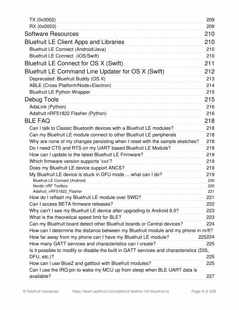
The first option is soldering in plain maleheaders, this lets you plug in the Featherinto a solderless breadboard
Another option is to go with socket femaleheaders. This won't let you plug theFeather into a breadboard but it will let youattach featherwings very easily
© Adafruit Industries https://learn.adafruit.com/adafruit-feather-m0-bluefruit-le Page 23 of 238
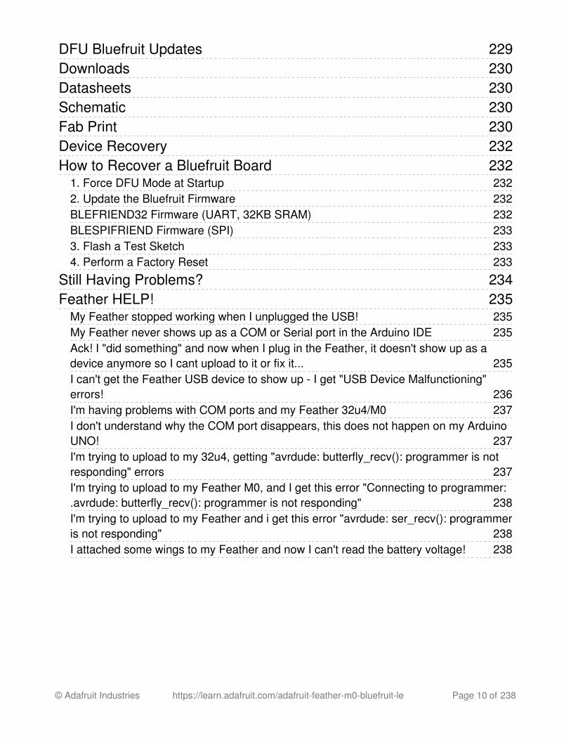
We also have 'slim' versions of the femaleheaders, that are a little shorter and give amore compact shape
© Adafruit Industries https://learn.adafruit.com/adafruit-feather-m0-bluefruit-le Page 24 of 238
Finally, there's the "Stacking Header"option. This one is sort of the best-of-both-worlds. You get the ability to plug into asolderless breadboard and plug afeatherwing on top. But its a little bulky
Soldering in Plain Headers
© Adafruit Industries https://learn.adafruit.com/adafruit-feather-m0-bluefruit-le Page 25 of 238
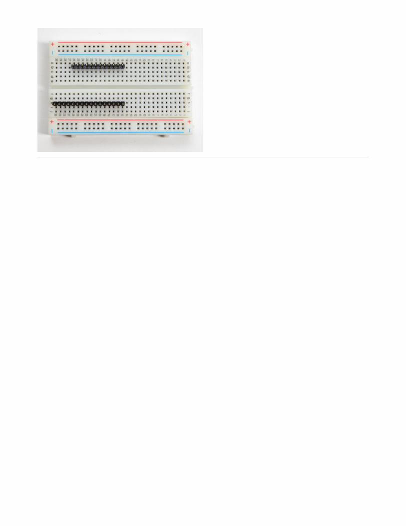
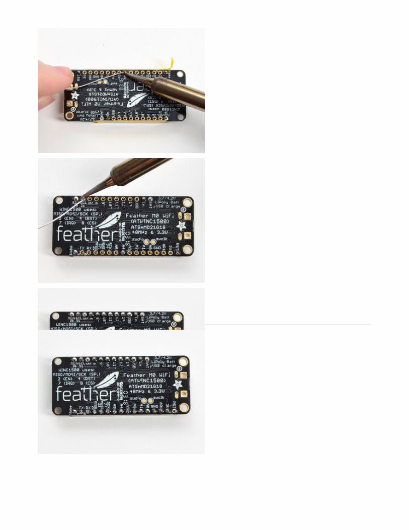
Prepare the header strip:Cut the strip to length if necessary. It will beeasier to solder if you insert it into abreadboard - long pins down
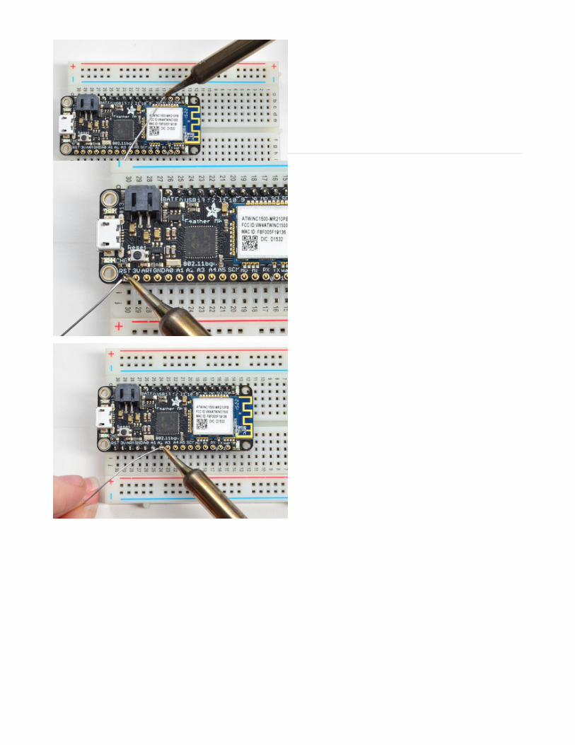
Add the breakout board:Place the breakout board over the pins sothat the short pins poke through thebreakout pads
And Solder!Be sure to solder all pins for reliableelectrical contact.
(For tips on soldering, be sure to check outour Guide to ExcellentSoldering (https://adafru.it/aTk)).
© Adafruit Industries https://learn.adafruit.com/adafruit-feather-m0-bluefruit-le Page 26 of 238
Solder the other strip as well.
© Adafruit Industries https://learn.adafruit.com/adafruit-feather-m0-bluefruit-le Page 27 of 238
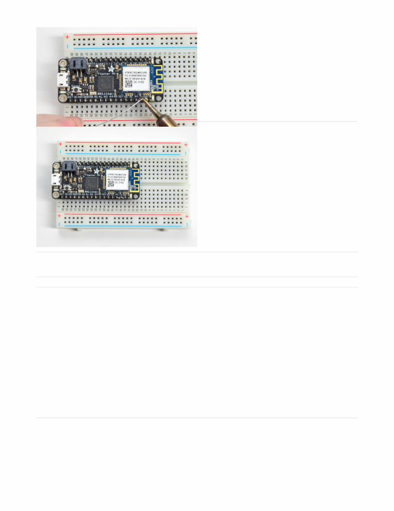
You're done! Check your solder jointsvisually and continue onto the next steps
Soldering on Female Header
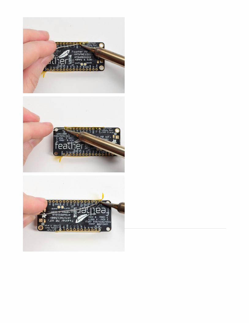
Tape In PlaceFor sockets you'll want to tape them inplace so when you flip over the board theydon't fall out
Flip & Tack SolderAfter flipping over, solder one or two pointson each strip, to 'tack' the header in place
© Adafruit Industries https://learn.adafruit.com/adafruit-feather-m0-bluefruit-le Page 28 of 238
And Solder!Be sure to solder all pins for reliableelectrical contact.
(For tips on soldering, be sure to check outour Guide to ExcellentSoldering (https://adafru.it/aTk)).
© Adafruit Industries https://learn.adafruit.com/adafruit-feather-m0-bluefruit-le Page 29 of 238
You're done! Check your solder jointsvisually and continue onto the next steps
© Adafruit Industries https://learn.adafruit.com/adafruit-feather-m0-bluefruit-le Page 30 of 238

© Adafruit Industries https://learn.adafruit.com/adafruit-feather-m0-bluefruit-le Page 31 of 238

Power Management
Battery + USB Power
We wanted to make the Feather easy to power both when connected to a computer as well
as via battery. There's two ways to power a Feather. You can connect with a MicroUSB cable(just plug into the jack) and the Feather will regulate the 5V USB down to 3.3V. You can alsoconnect a 4.2/3.7V Lithium Polymer (Lipo/Lipoly) or Lithium Ion (LiIon) battery to the JST jack.
This will let the Feather run on a rechargable battery. When the USB power is powered, it
will automatically switch over to USB for power, as well as start charging the battery (ifattached) at 100mA. This happens 'hotswap' style so you can always keep the Lipolyconnected as a 'backup' power that will only get used when USB power is lost.
The JST connector polarity is matched to Adafruit LiPoly batteries. Using wrongpolarity batteries can destroy your Feather
© Adafruit Industries https://learn.adafruit.com/adafruit-feather-m0-bluefruit-le Page 32 of 238

The above shows the Micro USB jack (left), Lipoly JST jack (top left), as well as the 3.3Vregulator and changeover diode (just to the right of the JST jack) and the Lipoly charging
circuitry (to the right of the Reset button). There's also a CHG LED, which will light up whilethe battery is charging. This LED might also flicker if the battery is not connected.
Power supplies
You have a lot of power supply options here! We bring out the BAT pin, which is tied to the
lipoly JST connector, as well as USB which is the +5V from USB if connected. We also have
the 3V pin which has the output from the 3.3V regulator. We use a 500mA peak regulator.While you can get 500mA from it, you can't do it continuously from 5V as it will overheat theregulator. It's fine for, say, powering an ESP8266 WiFi chip or XBee radio though, since thecurrent draw is 'spikey' & sporadic.
© Adafruit Industries https://learn.adafruit.com/adafruit-feather-m0-bluefruit-le Page 33 of 238

Measuring Battery
If you're running off of a battery, chances are you wanna know what the voltage is at! Thatway you can tell when the battery needs recharging. Lipoly batteries are 'maxed out' at 4.2Vand stick around 3.7V for much of the battery life, then slowly sink down to 3.2V or so beforethe protection circuitry cuts it off. By measuring the voltage you can quickly tell when you'reheading below 3.7V
To make this easy we stuck a double-100K resistor divider on the BAT pin, and connected it
to D9 (a.k.a analog #7 A7). You can read this pin's voltage, then double it, to get the batteryvoltage.
This voltage will 'float' at 4.2V when no battery is plugged in, due to the lipoly charger output,so its not a good way to detect if a battery is plugged in or not (there is no simple way todetect if a battery is plugged in)
#define VBATPIN A7 float measuredvbat = analogRead(VBATPIN);measuredvbat *= 2; // we divided by 2, so multiply backmeasuredvbat *= 3.3; // Multiply by 3.3V, our reference voltagemeasuredvbat /= 1024; // convert to voltageSerial.print("VBat: " ); Serial.println(measuredvbat);
© Adafruit Industries https://learn.adafruit.com/adafruit-feather-m0-bluefruit-le Page 34 of 238

ENable pin
If you'd like to turn off the 3.3V regulator, you can do that with the EN(able) pin. Simply tie this
pin to Ground and it will disable the 3V regulator. The BAT and USB pins will still bepowered
© Adafruit Industries https://learn.adafruit.com/adafruit-feather-m0-bluefruit-le Page 35 of 238

Arduino IDE SetupThe first thing you will need to do is to download the latest release of the Arduino IDE. You
will need to be using version 1.8 or higher for this guide
Arduino IDE Download
https://adafru.it/f1P
After you have downloaded and installed the latest version of Arduino IDE, you will need to
start the IDE and navigate to the Preferences menu. You can access it from the File menu in
Windows or Linux, or the Arduino menu on OS X.
A dialog will pop up just like the one shown below.
© Adafruit Industries https://learn.adafruit.com/adafruit-feather-m0-bluefruit-le Page 36 of 238

We will be adding a URL to the new Additional Boards Manager URLs option. The list ofURLs is comma separated, and you will only have to add each URL once. New Adafruitboards and updates to existing boards will automatically be picked up by the Board Managereach time it is opened. The URLs point to index files that the Board Manager uses to buildthe list of available & installed boards.
To find the most up to date list of URLs you can add, you can visit the list of third party boardURLs on the Arduino IDE wiki. We will only need to add one URL to the IDE in this example,
but you can add multiple URLS by separating them with commas. Copy and paste the link
below into the Additional Boards Manager URLs option in the Arduino IDE preferences.
https://adafruit.github.io/arduino-board-index/package_adafruit_index.json
© Adafruit Industries https://learn.adafruit.com/adafruit-feather-m0-bluefruit-le Page 37 of 238

Here's a short description of each of the Adafruit supplied packages that will be available inthe Board Manager when you add the URL:
Adafruit AVR Boards - Includes support for Flora, Gemma, Feather 32u4, Trinket, &Trinket Pro.
Adafruit SAMD Boards - Includes support for Feather M0, Metro M0, CircuitPlayground Express, Gemma M0 and Trinket M0
Arduino Leonardo & Micro MIDI-USB - This adds MIDI over USB support for the Flora,Feather 32u4, Micro and Leonardo using the arcore project.
If you have multiple boards you want to support, say ESP8266 and Adafruit, have both URLsin the text box separated by a comma (,)
Once done click OK to save the new preference settings. Next we will look at installingboards with the Board Manager.
Now continue to the next step to actually install the board support package!
© Adafruit Industries https://learn.adafruit.com/adafruit-feather-m0-bluefruit-le Page 38 of 238

Using with Arduino IDESince the Feather/Metro/Gemma/Trinket M0 use an ATSAMD21 chip running at 48 MHz, youcan pretty easily get it working with the Arduino IDE. Most libraries (including the popularones like NeoPixels and display) will work with the M0, especially devices & sensors that usei2c or SPI.
Now that you have added the appropriate URLs to the Arduino IDE preferences in the
previous page, you can open the Boards Manager by navigating to the Tools->Board menu.
Once the Board Manager opens, click on the category drop down menu on the top left hand
side of the window and select Contributed. You will then be able to select and install theboards supplied by the URLs added to the prefrences.
Install SAMD Support
First up, install the Arduino SAMD Boards version 1.6.15 or later
You can type Arduino SAMD in the top search bar, then when you see the entry, click Install
© Adafruit Industries https://learn.adafruit.com/adafruit-feather-m0-bluefruit-le Page 39 of 238

Install Adafruit SAMD
Next you can install the Adafruit SAMD package to add the board file definitions
You can type Adafruit SAMD in the top search bar, then when you see the entry, click Install
© Adafruit Industries https://learn.adafruit.com/adafruit-feather-m0-bluefruit-le Page 40 of 238

Even though in theory you don't need to - I recommend rebooting the IDE
Quit and reopen the Arduino IDE to ensure that all of the boards are properly installed. You
should now be able to select and upload to the new boards listed in the Tools->Board menu.
Select the matching board, the current options are:
Feather M0 (for use with any Feather M0 other than the Express)
Feather M0 Express
Metro M0 Express
Circuit Playground Express
Gemma M0
Trinket M0
Install Drivers (Windows 7 Only)
When you plug in the board, you'll need to possibly install a driver
Click below to download our Driver Installer
Download Adafruit Driver Installer
v2.0.0.0
https://adafru.it/zek
Download and run the installer
© Adafruit Industries https://learn.adafruit.com/adafruit-feather-m0-bluefruit-le Page 41 of 238

Run the installer! Since we bundle the SiLabs and FTDI drivers as well, you'll need to clickthrough the license
Select which drivers you want to install, the defaults will set you up with just about everyAdafruit board!
© Adafruit Industries https://learn.adafruit.com/adafruit-feather-m0-bluefruit-le Page 42 of 238

Click Install to do the installin'
Blink
Now you can upload your first blink sketch!
Plug in the Gemma M0, Trinket M0, Metro M0 or Feather M0 and wait for it to be recognizedby the OS (just takes a few seconds). It will create a serial/COM port, you can now select itfrom the dropdown, it'll even be 'indicated' as Trinket/Gemma/Metro/Feather M0!
© Adafruit Industries https://learn.adafruit.com/adafruit-feather-m0-bluefruit-le Page 43 of 238

Now load up the Blink example
And click upload! That's it, you will be able to see the LED blink rate change as you adapt the
delay() calls.
Sucessful Upload
If you have a successful upload, you'll get a bunch of red text that tells you that the devicewas found and it was programmed, verified & reset
// the setup function runs once when you press reset or power the boardvoid setup() { // initialize digital pin 13 as an output. pinMode(13, OUTPUT);}
// the loop function runs over and over again forevervoid loop() { digitalWrite(13, HIGH); // turn the LED on (HIGH is the voltage level) delay(1000); // wait for a second digitalWrite(13, LOW); // turn the LED off by making the voltage LOW delay(1000); // wait for a second}
If you are having issues, make sure you selected the matching Board in the menuthat matches the hardware you have in your hand.
© Adafruit Industries https://learn.adafruit.com/adafruit-feather-m0-bluefruit-le Page 44 of 238

Compilation Issues
If you get an alert that looks like
Cannot run program "{runtime.tools.arm-none-eabi-gcc.path}\bin\arm-non-eabi-g++"
Make sure you have installed the Arduino SAMD boards package, you need both Arduino &Adafruit SAMD board packages
© Adafruit Industries https://learn.adafruit.com/adafruit-feather-m0-bluefruit-le Page 45 of 238

Manually bootloading
If you ever get in a 'weird' spot with the bootloader, or you have uploaded code that crashes
and doesn't auto-reboot into the bootloader, click the RST button twice (like a double-click)toget back into the bootloader.
The red LED will pulse, so you know that its in bootloader mode.
Once it is in bootloader mode, you can select the newly created COM/Serial port and re-tryuploading.
You may need to go back and reselect the 'normal' USB serial port next time you want to usethe normal upload.
© Adafruit Industries https://learn.adafruit.com/adafruit-feather-m0-bluefruit-le Page 46 of 238

Ubuntu & Linux Issue Fix
Note if you're using Ubuntu 15.04 (or perhaps other more recent Linux distributions) there isan issue with the modem manager service which causes the Bluefruit LE micro to be difficultto program. If you run into errors like "device or resource busy", "bad file descriptor", or "portis busy" when attempting to program then you are hitting this issue.
The fix for this issue is to make sure Adafruit's custom udev rules are applied to your system. One of these rules is made to configure modem manager not to touch the Feather boardand will fix the programming difficulty issue. Follow the steps for installing Adafruit's udevrules on this page.
© Adafruit Industries https://learn.adafruit.com/adafruit-feather-m0-bluefruit-le Page 47 of 238

Adapting Sketches to M0The ATSAMD21 is a very nice little chip but its fairly new as Arduino-compatible cores go.
Most sketches & libraries will work but here's a few things we noticed!
The below note are for all M0 boards, but not all may apply (e.g. Trinket and Gemma M0 donot have ARef so you can skip the Analog References note!)
Analog References
If you'd like to use the ARef pin for a non-3.3V analog reference, the code to use isanalogReference(AR_EXTERNAL) (it's AR_EXTERNAL not EXTERNAL)
Pin Outputs & Pullups
The old-style way of turning on a pin as an input with a pullup is to use
pinMode(pin, INPUT)digitalWrite(pin, HIGH)
This is because the pullup-selection register is the same as the output-selection register.
For the M0, you can't do this anymore! Instead, use
pinMode(pin, INPUT_PULLUP)
which has the benefit of being backwards compatible with AVR.
Serial vs SerialUSB
99.9% of your existing Arduino sketches use Serial.print to debug and give output. For theOfficial Arduino SAMD/M0 core, this goes to the Serial5 port, which isn't exposed on the
Feather. The USB port for the Official Arduino M0 core, is called SerialUSB instead.
In the Adafruit M0 Core, we fixed it so that Serial goes to USB when you use a Feather M0so it will automatically work just fine.
However, on the off chance you are using the official Arduino SAMD core not the Adafruitversion (which really, we recommend you use our version because as you can see it canvary) & you want your Serial prints and reads to use the USB port, use SerialUSB instead ofSerial in your sketch
© Adafruit Industries https://learn.adafruit.com/adafruit-feather-m0-bluefruit-le Page 48 of 238

If you have existing sketches and code and you want them to work with the M0 without ahuge find-replace, put
#if defined(ARDUINO_SAMD_ZERO) && defined(SERIAL_PORT_USBVIRTUAL) // Required for Serial on Zero based boards #define Serial SERIAL_PORT_USBVIRTUAL#endif
right above the first function definition in your code. For example:
AnalogWrite / PWM on Feather/Metro M0
After looking through the SAMD21 datasheet, we've found that some of the options listed inthe multiplexer table don't exist on the specific chip used in the Feather M0.
For all SAMD21 chips, there are two peripherals that can generate PWM signals: TheTimer/Counter (TC) and Timer/Counter for Control Applications (TCC). Each SAMD21 hasmultiple copies of each, called 'instances'.
Each TC instance has one count register, one control register, and two output channels.Either channel can be enabled and disabled, and either channel can be inverted. The pinsconnected to a TC instance can output identical versions of the same PWM waveform, orcomplementary waveforms.
Each TCC instance has a single count register, but multiple compare registers and outputchannels. There are options for different kinds of waveform, interleaved switching,programmable dead time, and so on.
© Adafruit Industries https://learn.adafruit.com/adafruit-feather-m0-bluefruit-le Page 49 of 238

The biggest members of the SAMD21 family have five TC instances with two 'waveformoutput' (WO) channels, and three TCC instances with eight WO channels:
TC[0-4],WO[0-1]TCC[0-2],WO[0-7]
And those are the ones shown in the datasheet's multiplexer tables.
The SAMD21G used in the Feather M0 only has three TC instances with two output channels,and three TCC instances with eight output channels:
TC[3-5],WO[0-1]
TCC[0-2],WO[0-7]
Tracing the signals to the pins broken out on the Feather M0, the following pins can't doPWM at all:
Analog pin A5
The following pins can be configured for PWM without any signal conflicts as long as the SPI,I2C, and UART pins keep their protocol functions:
Digital pins 5, 6, 9, 10, 11, 12, and 13
Analog pins A3 and A4
If only the SPI pins keep their protocol functions, you can also do PWM on the following pins:
TX and SDA (Digital pins 1 and 20)
analogWrite() PWM range
On AVR, if you set a pin's PWM with analogWrite(pin, 255) it will turn the pin fully HIGH. On theARM cortex, it will set it to be 255/256 so there will be very slim but still-existing pulses-to-0V. If you need the pin to be fully on, add test code that checks if you are trying toanalogWrite(pin, 255) and, instead, does a digitalWrite(pin, HIGH)
Missing header files
there might be code that uses libraries that are not supported by the M0 core. For example ifyou have a line with
© Adafruit Industries https://learn.adafruit.com/adafruit-feather-m0-bluefruit-le Page 50 of 238

#include <util/delay.h>
you'll get an error that says
fatal error: util/delay.h: No such file or directory #include <util/delay.h> ^compilation terminated.Error compiling.
In which case you can simply locate where the line is (the error will give you the file nameand line number) and 'wrap it' with #ifdef's so it looks like:
The above will also make sure that header file isn't included for other architectures
If the #include is in the arduino sketch itself, you can try just removing the line.
Bootloader Launching
For most other AVRs, clicking reset while plugged into USB will launch the bootloadermanually, the bootloader will time out after a few seconds. For the M0, you'll need to doubleclick the button. You will see a pulsing red LED to let you know you're in bootloader mode.Once in that mode, it wont time out! Click reset again if you want to go back to launchingcode
Aligned Memory Access
This is a little less likely to happen to you but it happened to me! If you're used to 8-bitplatforms, you can do this nice thing where you can typecast variables around. e.g.
uint8_t mybuffer[4];float f = (float)mybuffer;
You can't be guaranteed that this will work on a 32-bit platform because mybuffer might notbe aligned to a 2 or 4-byte boundary. The ARM Cortex-M0 can only directly access data on16-bit boundaries (every 2 or 4 bytes). Trying to access an odd-boundary byte (on a 1 or 3
#if !defined(ARDUINO_ARCH_SAM) && !defined(ARDUINO_ARCH_SAMD) && !defined(ESP8266) && !defined(ARDUINO_ARCH_STM32F2) #include <util/delay.h>#endif
© Adafruit Industries https://learn.adafruit.com/adafruit-feather-m0-bluefruit-le Page 51 of 238

byte location) will cause a Hard Fault and stop the MCU. Thankfully, there's an easy workaround ... just use memcpy!
uint8_t mybuffer[4];float f;memcpy(f, mybuffer, 4)
Floating Point Conversion
Like the AVR Arduinos, the M0 library does not have full support for converting floating pointnumbers to ASCII strings. Functions like sprintf will not convert floating point. Fortunately,the standard AVR-LIBC library includes the dtostrf function which can handle the conversionfor you.
Unfortunately, the M0 run-time library does not have dtostrf. You may see some references
to using #include <avr/dtostrf.h> to get dtostrf in your code. And while it will compile, it does
not work.
Instead, check out this thread to find a working dtostrf function you can include in your code:
http://forum.arduino.cc/index.php?topic=368720.0
How Much RAM Available?
The ATSAMD21G18 has 32K of RAM, but you still might need to track it for some reason. Youcan do so with this handy function:
Thx to http://forum.arduino.cc/index.php?topic=365830.msg2542879#msg2542879 for thetip!
Storing data in FLASH
If you're used to AVR, you've probably used PROGMEM to let the compiler know you'd liketo put a variable or string in flash memory to save on RAM. On the ARM, its a little easier,
extern "C" char *sbrk(int i);
int FreeRam () { char stack_dummy = 0; return &stack_dummy - sbrk(0);}
© Adafruit Industries https://learn.adafruit.com/adafruit-feather-m0-bluefruit-le Page 52 of 238

simply add const before the variable name:
const char str[] = "My very long string";
That string is now in FLASH. You can manipulate the string just like RAM data, the compilerwill automatically read from FLASH so you dont need special progmem-knowledgeablefunctions.
You can verify where data is stored by printing out the address:
Serial.print("Address of str $"); Serial.println((int)&str, HEX);
If the address is $2000000 or larger, its in SRAM. If the address is between $0000 and$3FFFF Then it is in FLASH
© Adafruit Industries https://learn.adafruit.com/adafruit-feather-m0-bluefruit-le Page 53 of 238

Installing BLE LibraryInstall the Adafruit nRF51 BLE Library
In order to try out our demos, you'll need to download the Adafruit BLE library for the nRF51based modules such as this one (a.k.a. Adafruit_BluefruitLE_nRF51)
You can check out the code here at github, but its likely easier to just download by clicking:
Download the Adafruit nRF51
BluefruitLE library
https://adafru.it/f4W
Rename the uncompressed folder Adafruit_BluefruitLE_nRF51 and check that the
Adafruit_BluefruitLE_nRF51 folder contains Adafruit_BLE.cpp and Adafruit_BLE.h (as wellas a bunch of other files)
Place the Adafruit_BluefruitLE_nRF51 library folder your arduinosketchfolder/libraries/folder.
You may need to create the libraries subfolder if its your first library. Restart the IDE.
We also have a great tutorial on Arduino library installation at:http://learn.adafruit.com/adafruit-all-about-arduino-libraries-install-use
After restarting, check that you see the library folder with examples:
© Adafruit Industries https://learn.adafruit.com/adafruit-feather-m0-bluefruit-le Page 54 of 238

Run first example
Lets begin with the beginner project, which we can use to do basic tests. To open the
ATCommand sketch, click on the File > Examples > Adafruit_BluefruitLE_nRF51 folder in the
Arduino IDE and select atcommand:
This will open up a new instance of the example in the IDE, as shown below:
© Adafruit Industries https://learn.adafruit.com/adafruit-feather-m0-bluefruit-le Page 55 of 238

Go to the second tab labeled BluefruitConfig.h and find these lines
Don't upload the sketch yet! You will have to begin by changing the configuration.
© Adafruit Industries https://learn.adafruit.com/adafruit-feather-m0-bluefruit-le Page 56 of 238

And change (if it isnt already) the last line to:
(The Bluefruit Feather has the reset on digital #4 not #6)
Now go back to the main tab atcommand and look for this line of code
Make sure that the second line is uncommented (it should be)
Uploading to the Feather Bluefruit LE
It's pretty easy to upload, first up make sure you have Adafruit Feather M0 selected on theboards dropdown
// SHARED SPI SETTINGS// ----------------------------------------------------------------------------------------------// The following macros declare the pins to use for HW and SW SPI communication.// SCK, MISO and MOSI should be connected to the HW SPI pins on the Uno when// using HW SPI. This should be used with nRF51822 based Bluefruit LE modules// that use SPI (Bluefruit LE SPI Friend).// ----------------------------------------------------------------------------------------------#define BLUEFRUIT_SPI_CS 8#define BLUEFRUIT_SPI_IRQ 7#define BLUEFRUIT_SPI_RST 6 // Optional but recommended, set to -1 if unused
#define BLUEFRUIT_SPI_RST 4 // Optional but recommended, set to -1 if unused
/* ...hardware SPI, using SCK/MOSI/MISO hardware SPI pins and then user selected CS/IRQ/RST */ Adafruit_BluefruitLE_SPI ble(BLUEFRUIT_SPI_CS, BLUEFRUIT_SPI_IRQ, BLUEFRUIT_SPI_RST
OK now you can upload to the Bluefruit Feather!
If you're using Ubuntu 15.04 or other Linux distributions and run into errorsattempting to upload a program to the board, scroll up to the Ubuntu and Linuxissue fix in the previous section
© Adafruit Industries https://learn.adafruit.com/adafruit-feather-m0-bluefruit-le Page 57 of 238

Also, in the Ports menu, look for the port labeled as such:
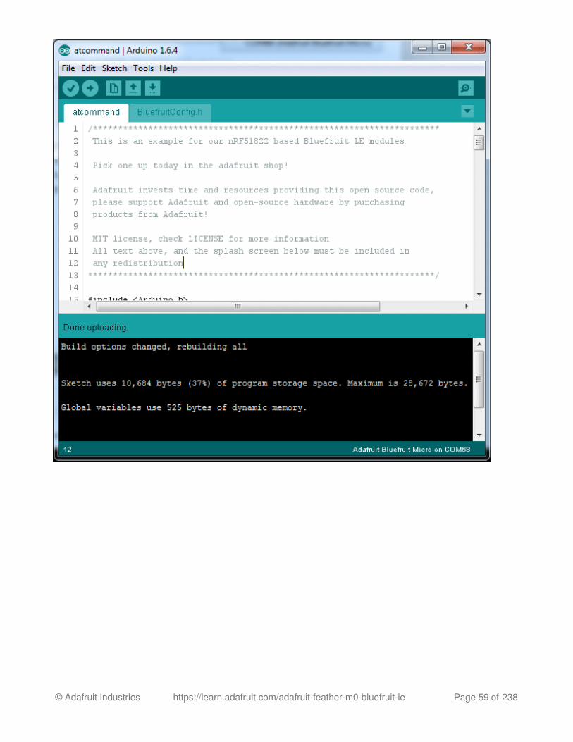
Now click the upload button on the Arduino IDE (or File Menu -> Upload)
If all is good you will see Done Uploading in the status bar
© Adafruit Industries https://learn.adafruit.com/adafruit-feather-m0-bluefruit-le Page 58 of 238
© Adafruit Industries https://learn.adafruit.com/adafruit-feather-m0-bluefruit-le Page 59 of 238

Compilation Issues
If you get an alert that looks like
Cannot run program "{runtime.tools.arm-none-eabi-gcc.path}\bin\arm-non-eabi-g++"
Make sure you have installed the Arduino SAMD boards package, you need both Arduino &Adafruit SAMD board packages
Manually bootloading
If you ever get in a 'weird' spot with the bootloader, or you have uploaded code that crashes
and doesn't auto-reboot into the bootloader, click the RST button twice (like a double-click)toget back into the bootloader.
The red LED will pulse, so you know that its in bootloader mode.
Once it is in bootloader mode, you can select the newly created COM/Serial port and re-tryuploading.
© Adafruit Industries https://learn.adafruit.com/adafruit-feather-m0-bluefruit-le Page 60 of 238

You may need to go back and reselect the 'normal' USB serial port next time you want to usethe normal upload.
Run the sketch
OK check again that the correct port is selected
Then open up the Serial console. You will see the following:
© Adafruit Industries https://learn.adafruit.com/adafruit-feather-m0-bluefruit-le Page 61 of 238

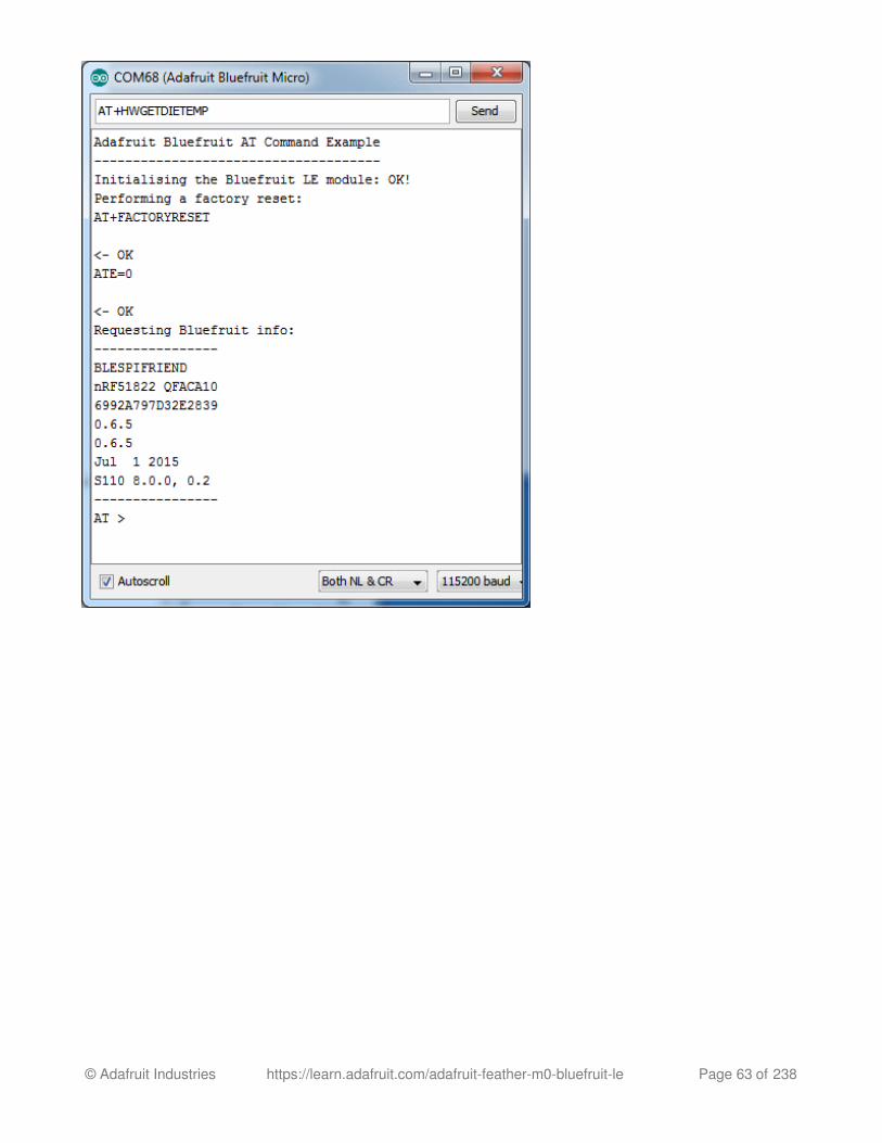
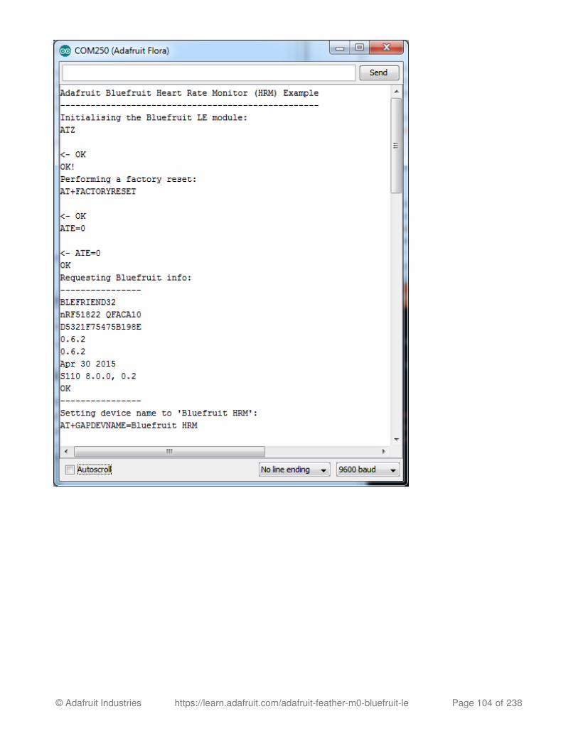
This sketch starts by doing a factory reset, then querying the BLE radio for details. Thesedetails will be useful if you are debugging the radio. If you see the information as above,you're working! (Note that the dates and version numbers may vary)
AT command testing
Now you can try out some AT commands - check the rest of the learn guide for a full list.
We'll just start with AT+HWGETDIETEMP which will return the approximate ambienttemperature of the BLE chipset
© Adafruit Industries https://learn.adafruit.com/adafruit-feather-m0-bluefruit-le Page 62 of 238
© Adafruit Industries https://learn.adafruit.com/adafruit-feather-m0-bluefruit-le Page 63 of 238

OK now you know how to upload/test/communicate with your Feather M0 Bluefruit. Next up we have abunch of tutorials who can follow for checking out the bluetooth le radio and apps.
For all the following examples, we share the same code between various modules so don't forget tomake sure you have the RESET pin set to 4 in BluefruitConfig.h for each sketch beforeuploading, and that Hardware SPI mode is selected by checking for
/* ...hardware SPI, using SCK/MOSI/MISO hardware SPI pins and then user selected CS/IRQ/RST */Adafruit_BluefruitLE_SPI ble(BLUEFRUIT_SPI_CS, BLUEFRUIT_SPI_IRQ, BLUEFRUIT_SPI_RST
© Adafruit Industries https://learn.adafruit.com/adafruit-feather-m0-bluefruit-le Page 64 of 238

Configuration!
Which board do you have?
There's a few products under the Bluefruit name:
If you are using the Bluefruit LE Shield thenyou have an SPI-connected NRF51822
module. You can use this with Atmega328
(Arduino UNO or compatible),
ATmega32u4 (Arduino Leonardo,
compatible) or ATSAMD21 (Arduino Zero,compatible) and possibly others. Your pinouts are Hardware SPI, CS = 8,
IRQ = 7, RST = 4
Bluefruit Micro or Feather 32u4BluefruitIf you have a Bluefruit Micro or Feather32u4 Bluefruit LE then you have anATmega32u4 chip with Hardware SPI, CS =
8, IRQ = 7, RST = 4
Feather M0 Bluefruit LEIf you have a Feather M0 Bluefruit LE thenyou have an ATSAMD21 chip with
Hardware SPI, CS = 8, IRQ = 7, RST = 4
Before you start uploading any of the example sketches, you'll need toCONFIGURE the Bluefruit interface - there's a lot of options so pay close attention!
© Adafruit Industries https://learn.adafruit.com/adafruit-feather-m0-bluefruit-le Page 65 of 238
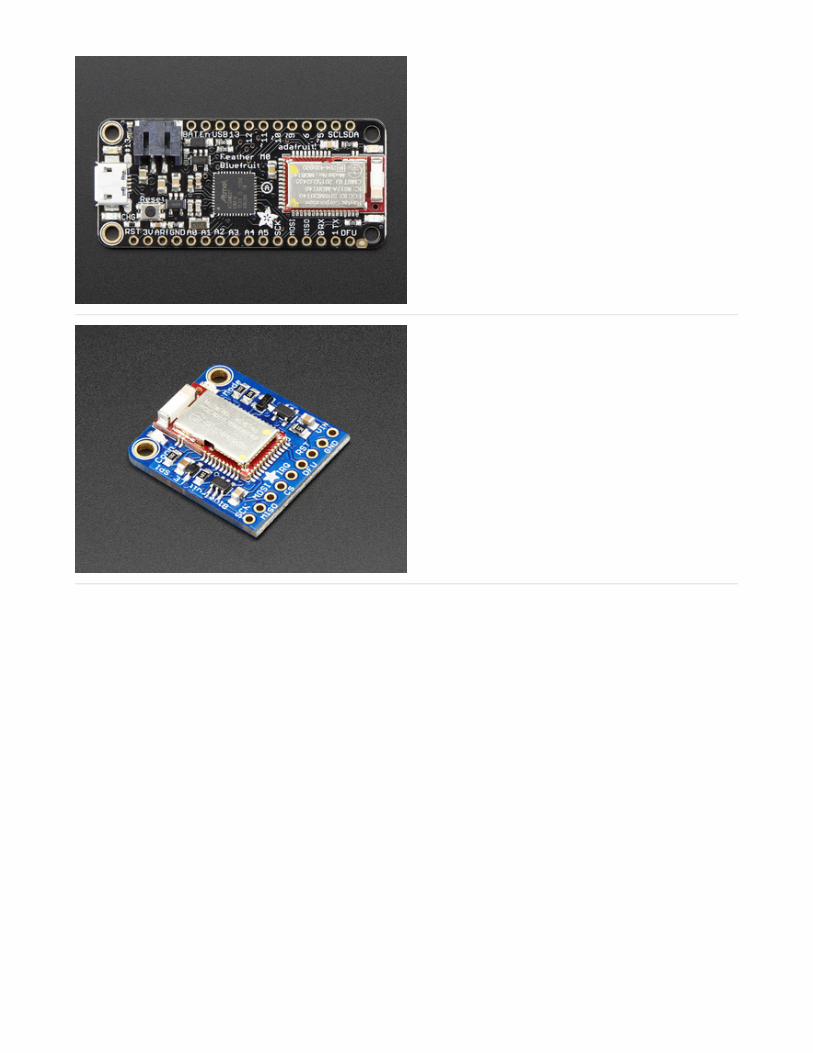
Bluefruit LE SPI FriendIf you have a stand-alone module, you havea bit of flexibility with wiring however westrongly recommend Hardware SPI, CS = 8,
IRQ = 7, RST = 4
You can use this with just about anymicrocontroller with 5 or 6 pins
Bluefruit LE UART Friend or FloraBLEIf you have a stand-alone UART moduleyou have some flexibility with wiring.However we suggest hardware UART ifpossible. You will likely need to use theflow control CTS pin if you are not using
hardware UART. There's also a MODE pin
You can use this with just about anymicrocontroller with at least 3 pins, but bestused with a Hardware Serial/UART capablechip!
© Adafruit Industries https://learn.adafruit.com/adafruit-feather-m0-bluefruit-le Page 66 of 238

Configure the Pins Used
You'll want to check the Bluefruit Config to set up the pins you'll be using for UART or SPI
Each example sketch has a secondary tab with configuration details. You'll want to edit andsave the sketch to your own documents folder once set up.
Common settings:
You can set up how much RAM to set aside for a communication buffer and whether youwant to have full debug output. Debug output is 'noisy' on the serial console but is handysince you can see all communication between the micro and the BLE
© Adafruit Industries https://learn.adafruit.com/adafruit-feather-m0-bluefruit-le Page 67 of 238

Software UART
If you are using Software UART, you can set up which pins are going to be used for RX, TX,and CTS flow control. Some microcontrollers are limited on which pins can be used! Checkthe SoftwareSerial library documentation for more details
Hardware UART
If you have Hardware Serial, there's a 'name' for it, usually Serial1 - you can set that up here:
Mode Pin
For both hardware and software serial, you will likely want to define the MODE pin. There's afew sketches that dont use it, instead depending on commands to set/unset the mode. Itsbest to use the MODE pin if you have a GPIO to spare!
SPI Pins
// ----------------------------------------------------------------------------------------------// These settings are used in both SW UART, HW UART and SPI mode// ----------------------------------------------------------------------------------------------#define BUFSIZE 128 // Size of the read buffer for incoming data#define VERBOSE_MODE true // If set to 'true' enables debug output
// SOFTWARE UART SETTINGS#define BLUEFRUIT_SWUART_RXD_PIN 9 // Required for software serial!#define BLUEFRUIT_SWUART_TXD_PIN 10 // Required for software serial!#define BLUEFRUIT_UART_CTS_PIN 11 // Required for software serial!#define BLUEFRUIT_UART_RTS_PIN -1 // Optional, set to -1 if unused
// HARDWARE UART SETTINGS#ifdef Serial1 // this makes it not complain on compilation if there's no Serial1 #define BLUEFRUIT_HWSERIAL_NAME Serial1#endif
#define BLUEFRUIT_UART_MODE_PIN 12 // Set to -1 if unused
© Adafruit Industries https://learn.adafruit.com/adafruit-feather-m0-bluefruit-le Page 68 of 238

For both Hardware and Software SPI, you'll want to set the CS (chip select) line, IRQ (interrupt
request) line and if you have a pin to spare, RST (Reset)
Software SPI Pins
If you don't have a hardware SPI port available, you can use any three pins...its a tad slowerbut very flexible
Select the Serial Bus
Once you've configured your pin setup in the BluefruitConfig.h file, you can now check andadapt the example sketch.
The Adafruit_BluefruitLE_nRF51 library supports four different serial bus options, depending
on the HW you are using: SPI both hardware and software type, and UART both hardwareand software type.
UART Based Boards (Bluefruit LE UART Friend & Flora BLE)
This is for Bluefruit LE UART Friend & Flora BLE boards. You can use either software serial orhardware serial. Hardware serial is higher quality, and less risky with respect to losing data.However, you may not have hardware serial available! Software serial does work just finewith flow-control and we do have that available at the cost of a single GPIO pin.
// SHARED SPI SETTINGS#define BLUEFRUIT_SPI_CS 8#define BLUEFRUIT_SPI_IRQ 7#define BLUEFRUIT_SPI_RST 4 // Optional but recommended, set to -1 if unused
// SOFTWARE SPI SETTINGS#define BLUEFRUIT_SPI_SCK 13#define BLUEFRUIT_SPI_MISO 12#define BLUEFRUIT_SPI_MOSI 11
Refer to the table above to determine whether you have SPI or UART controlledBluefruits!
© Adafruit Industries https://learn.adafruit.com/adafruit-feather-m0-bluefruit-le Page 69 of 238

For software serial (Arduino Uno, Adafruit Metro) you should uncomment the software serialcontructor below, and make sure the other three options (hardware serial & SPI) arecommented out.
For boards that require hardware serial (Adafruit Flora, etc.), uncomment the hardware serialconstructor, and make sure the other three options are commented out
SPI Based Boards (Bluefruit LE SPI Friend)
For SPI based boards, you should uncomment the hardware SPI constructor below, makingsure the other constructors are commented out:
If for some reason you can't use HW SPI, you can switch to software mode to bit-bang the SPItransfers via the following constructor:
// Create the bluefruit object, either software serial...uncomment these linesSoftwareSerial bluefruitSS = SoftwareSerial(BLUEFRUIT_SWUART_TXD_PIN, BLUEFRUIT_SWUART_RXD_PIN
Adafruit_BluefruitLE_UART ble(bluefruitSS, BLUEFRUIT_UART_MODE_PIN, BLUEFRUIT_UART_CTS_PIN, BLUEFRUIT_UART_RTS_PIN);
/* ...or hardware serial, which does not need the RTS/CTS pins. Uncomment this line */Adafruit_BluefruitLE_UART ble(BLUEFRUIT_HWSERIAL_NAME, BLUEFRUIT_UART_MODE_PIN);
/* ...hardware SPI, using SCK/MOSI/MISO hardware SPI pins and then user selected CS/IRQ/RST */Adafruit_BluefruitLE_SPI ble(BLUEFRUIT_SPI_CS, BLUEFRUIT_SPI_IRQ, BLUEFRUIT_SPI_RST
/* ...software SPI, using SCK/MOSI/MISO user-defined SPI pins and then user selected CS/IRQ/RST */Adafruit_BluefruitLE_SPI ble(BLUEFRUIT_SPI_SCK, BLUEFRUIT_SPI_MISO, BLUEFRUIT_SPI_MOSI, BLUEFRUIT_SPI_CS, BLUEFRUIT_SPI_IRQ, BLUEFRUIT_SPI_RST);
© Adafruit Industries https://learn.adafruit.com/adafruit-feather-m0-bluefruit-le Page 70 of 238

ATCommandThe ATCommand example allows you to execute AT commands from your sketch, and seethe results in the Serial Monitor. This can be useful for debugging, or just testing differentcommands out to see how they work in the real world. It's a good one to start with!
Opening the Sketch
To open the ATCommand sketch, click on the File > Examples > Adafruit_BluefruitLE_nRF51
folder in the Arduino IDE and select atcommand:
This will open up a new instance of the example in the IDE, as shown below:
© Adafruit Industries https://learn.adafruit.com/adafruit-feather-m0-bluefruit-le Page 71 of 238

Configuration
Check the Configuration! page earlier to set up the sketch for Software/Hardware UART orSoftware/Hardware SPI. The default is hardware SPI
If using software or hardware Serial UART:
This tutorial does not need to use the MODE pin, make sure you have the mode switch
© Adafruit Industries https://learn.adafruit.com/adafruit-feather-m0-bluefruit-le Page 72 of 238

in CMD mode if you do not configure & connect a MODE pin
Don't forget to also connect the CTS pin on the Bluefruit to ground if you are not using
it! (The Flora has this already done)
Running the Sketch
Once you upload the sketch to your board (via the arrow-shaped upload icon), and the
upload process has finished, open up the Serial Monitor via Tools > Serial Monitor, and make
sure that the baud rate in the lower right-hand corner is set to 115200:
To send an AT command to the Bluefruit LE module, enter the command in the textbox at the
top of the Serial Monitor and click the Send button:
© Adafruit Industries https://learn.adafruit.com/adafruit-feather-m0-bluefruit-le Page 73 of 238

The response to the AT command will be displayed in the main part of the Serial
Monitor. The response from 'ATI' is shown below:
You can do pretty much anything at this prompt, with the AT command set. Try AT+HELP to
get a list of all commands, and try out ones like AT+HWGETDIETEMP (get temperature at the
nRF51822 die) and AT+HWRANDOM (generate a random number)
© Adafruit Industries https://learn.adafruit.com/adafruit-feather-m0-bluefruit-le Page 74 of 238

© Adafruit Industries https://learn.adafruit.com/adafruit-feather-m0-bluefruit-le Page 75 of 238

BLEUartThe BLEUart example sketch allows you to send and receive text data between the Arduinoand a connected Bluetooth Low Energy Central device on the other end (such as you mobile
phone using the Adafruit Bluefruit LE Connect application for Android or iOS in UARTmode).
Opening the Sketch
To open the ATCommand sketch, click on the File > Examples > Adafruit_BluefruitLE_nRF51
folder in the Arduino IDE and select bleuart_cmdmode:
This will open up a new instance of the example in the IDE, as shown below:
© Adafruit Industries https://learn.adafruit.com/adafruit-feather-m0-bluefruit-le Page 76 of 238

Configuration
Check the Configuration! page earlier to set up the sketch for Software/Hardware UART orSoftware/Hardware SPI. The default is hardware SPI
If using software or hardware Serial UART:
© Adafruit Industries https://learn.adafruit.com/adafruit-feather-m0-bluefruit-le Page 77 of 238

This tutorial does not need to use the MODE pin, make sure you have the mode switch
in CMD mode if you do not configure & connect a MODE pin
Don't forget to also connect the CTS pin on the Bluefruit to ground if you are not using
it! (The Flora has this already done)
Running the Sketch
Once you upload the sketch to your board (via the arrow-shaped upload icon), and the
upload process has finished, open up the Serial Monitor via Tools > Serial Monitor, and make
sure that the baud rate in the lower right-hand corner is set to 115200:
Once you see the request, use the App to connect to the Bluefruit LE module in UART modeso you get the text box on your phone
© Adafruit Industries https://learn.adafruit.com/adafruit-feather-m0-bluefruit-le Page 78 of 238

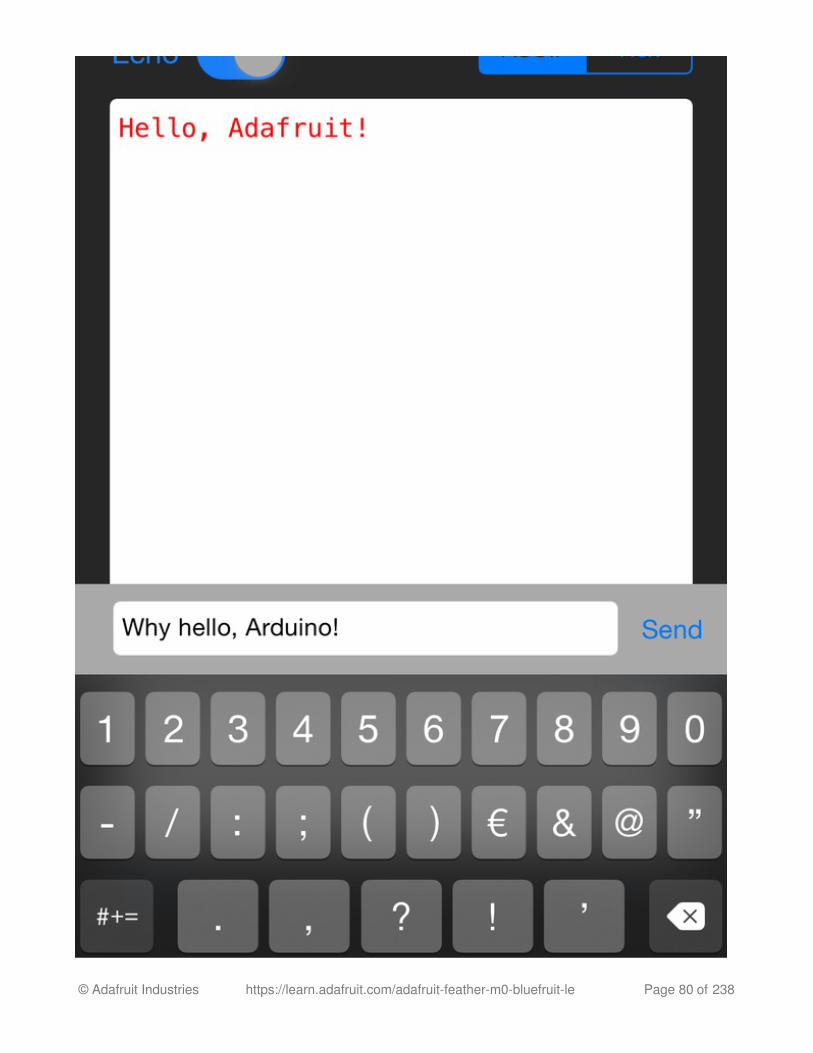
Any text that you type in the box at the top of the Serial Monitor will be sent to theconnected phone, and any data sent from the phone will be displayed in the serial monitor:
You can see the incoming string here in the Adafruit Bluefruit LE Connect app below (iOS inthis case):
© Adafruit Industries https://learn.adafruit.com/adafruit-feather-m0-bluefruit-le Page 79 of 238
© Adafruit Industries https://learn.adafruit.com/adafruit-feather-m0-bluefruit-le Page 80 of 238

The response text ('Why hello, Arduino!') can be seen below:
© Adafruit Industries https://learn.adafruit.com/adafruit-feather-m0-bluefruit-le Page 81 of 238

HIDKeyboardThe HIDKeyboard example shows you how you can use the built-in HID keyboard ATcommands to send keyboard data to any BLE-enabled Android or iOS phone, or otherdevice that supports BLE HID peripherals.
Opening the Sketch
To open the ATCommand sketch, click on the File > Examples > Adafruit_BluefruitLE_nRF51
folder in the Arduino IDE and select hidkeyboard:
This will open up a new instance of the example in the IDE, as shown below:
© Adafruit Industries https://learn.adafruit.com/adafruit-feather-m0-bluefruit-le Page 82 of 238

Configuration
Check the Configuration! page earlier to set up the sketch for Software/Hardware UART orSoftware/Hardware SPI. The default is hardware SPI
If using software or hardware Serial UART:
This tutorial does not need to use the MODE pin, make sure you have the mode switch
© Adafruit Industries https://learn.adafruit.com/adafruit-feather-m0-bluefruit-le Page 83 of 238

in CMD mode!
Don't forget to also connect the CTS pin on the Bluefruit to ground if you are not using
it! (The Flora has this already done)
Running the Sketch
Once you upload the sketch to your board (via the arrow-shaped upload icon), and the
upload process has finished, open up the Serial Monitor via Tools > Serial Monitor, and make
sure that the baud rate in the lower right-hand corner is set to 115200:
© Adafruit Industries https://learn.adafruit.com/adafruit-feather-m0-bluefruit-le Page 84 of 238

To send keyboard data, type anything into the textbox at the top of the Serial Monitor and
click the Send button.
Bonding the HID Keyboard
Before you can use the HID keyboard, you will need to 'bond' it to your phone or PC. Thebonding process establishes a permanent connection between the two devices, meaningthat as soon as your phone or PC sees the Bluefruit LE module again it will automaticallyconnect.
The exact procedures for bonding the keyboard will varying from one platform to another.
Android
To bond the keyboard on a Bluetooth Low Energy enabled Android device, go to
the Settings application and click the Bluetooth icon.
When you no longer need a bond, or wish to bond the Bluefruit LE module toanother device, be sure to delete the bonding information on the phone or PC,otherwise you may not be able to connect on a new device!
These screenshots are based on Android 5.0 running on a Nexus 7 2013. The exactappearance may vary depending on your device and OS version.
© Adafruit Industries https://learn.adafruit.com/adafruit-feather-m0-bluefruit-le Page 85 of 238

Inside the Bluetooth setting panel you should see the Bluefruit LE module advertising itself
as Bluefruit Keyboard under the 'Available devices' list:
Tapping the device will start the bonding process, which should end with the BluefruitKeyboard device being moved to a new 'Paired devices' list with 'Connected' writtenunderneath the device name:
© Adafruit Industries https://learn.adafruit.com/adafruit-feather-m0-bluefruit-le Page 86 of 238

To delete the bonding information, click the gear icon to the right of the device name and
the click the Forget button:
iOS
To bond the keyboard on an iOS device, go to the Settings application on your phone, and
click the Bluetooth menu item.
The keyboard should appear under the OTHER DEVICES list:
© Adafruit Industries https://learn.adafruit.com/adafruit-feather-m0-bluefruit-le Page 87 of 238

Once the bonding process is complete the device will be moved to the MY DEVICEScategory, and you can start to use the Bluefruit LE module as a keyboard:
© Adafruit Industries https://learn.adafruit.com/adafruit-feather-m0-bluefruit-le Page 88 of 238

To unbond the device, click the 'info' icon and then select the Forget this Device option inthe menu:
OS X
To bond the keyboard on an OS X device, go to the Bluetooth Preferences window and click
the Pair button beside the Bluefruit Keyboard device generated by this example sketch:
© Adafruit Industries https://learn.adafruit.com/adafruit-feather-m0-bluefruit-le Page 89 of 238

To unbond the device once it has been paired, click the small 'x' icon beside Bluefruit
Keyboard:
© Adafruit Industries https://learn.adafruit.com/adafruit-feather-m0-bluefruit-le Page 90 of 238

... and then click the Remove button when the confirmation dialogue box pops up:
© Adafruit Industries https://learn.adafruit.com/adafruit-feather-m0-bluefruit-le Page 91 of 238

ControllerThe Controller sketch allows you to turn your BLE-enabled iOS or Android device in a hand-held controller or an external data source, taking advantage of the wealth of sensors on yourphone or tablet.
You can take accelerometer or quaternion data from your phone, and push it out to yourArduino via BLE, or get the latest GPS co-ordinates for your device without having topurchase (or power!) any external HW.
Opening the Sketch
To open the Controller sketch, click on the File > Examples > Adafruit_BluefruitLE_nRF51
folder in the Arduino IDE and select controller:
This will open up a new instance of the example in the IDE, as shown below:
© Adafruit Industries https://learn.adafruit.com/adafruit-feather-m0-bluefruit-le Page 92 of 238

Configuration
Check the Configuration! page earlier to set up the sketch for Software/Hardware UART orSoftware/Hardware SPI. The default is hardware SPI
If using software or hardware Serial UART:
This tutorial will also be easier to use if you wire up the MODE pin, you can use any pinbut our tutorial has pin 12 by default. You can change this to any pin. If you do not set
the MODE pin then make sure you have the mode switch in CMD modeIf you are using a Flora or otherwise don't want to wire up the Mode pin, set the
© Adafruit Industries https://learn.adafruit.com/adafruit-feather-m0-bluefruit-le Page 93 of 238

BLUEFRUIT_UART_MODE_PIN to -1 in the configuration tab so that the sketch will usethe +++ method to switch between Command and Data mode!
Don't forget to also connect the CTS pin on the Bluefruit to ground if you are not using
it! (The Flora has this already done)
Running the Sketch
Once you upload the sketch to your board (via the arrow-shaped upload icon), and the
upload process has finished, open up the Serial Monitor via Tools > Serial Monitor, and make
sure that the baud rate in the lower right-hand corner is set to 115200:
Using Bluefruit LE Connect in Controller Mode
Once the sketch is running you can open Adafruit's Bluefruit LE Connect application
(available for Android or iOS) and use the Controller application to interact with the sketch.
© Adafruit Industries https://learn.adafruit.com/adafruit-feather-m0-bluefruit-le Page 94 of 238

(If you're new to Bluefruit LE Connect, have a look at our dedicated Bluefruit LE Connectlearning guide.)
On the welcome screen, select the Adafruit Bluefruit LE device from the list of BLE devicesin range:
Then from the activity list select Controller:
This will bring up a list of data points you can send from your phone or tablet to your BluefruitLE module, by enabling or disabling the appropriate sensor(s).
© Adafruit Industries https://learn.adafruit.com/adafruit-feather-m0-bluefruit-le Page 95 of 238

Streaming Sensor Data
You can take Quaternion (absolute orientation), Accelerometer, Gyroscope, Magnetometer orGPS Location data from your phone and send it directly to your Arduino from the Controlleractivity.
By enabling the Accelerometer field, for example, you should see accelerometer dataupdate in the app:
The data is parsed in the example sketch and output to the Serial Monitor as follows:
© Adafruit Industries https://learn.adafruit.com/adafruit-feather-m0-bluefruit-le Page 96 of 238

Note that even though we only print 2 decimal points, the values are received from the Appas a full 4-byte floating point.
Control Pad Module
You can also use the Control Pad Module to capture button presses and releases byselecting the appropriate menu item:
Accel 0.20 -0.51 -0.76Accel 0.22 -0.50 -0.83Accel 0.25 -0.51 -0.83Accel 0.21 -0.47 -0.76Accel 0.27 -0.48 -0.82
© Adafruit Industries https://learn.adafruit.com/adafruit-feather-m0-bluefruit-le Page 97 of 238

This will bring up the Control Pad panel, shown below:
Button presses and releases will all be logged to the Serial Monitor with the ID of the buttonused:
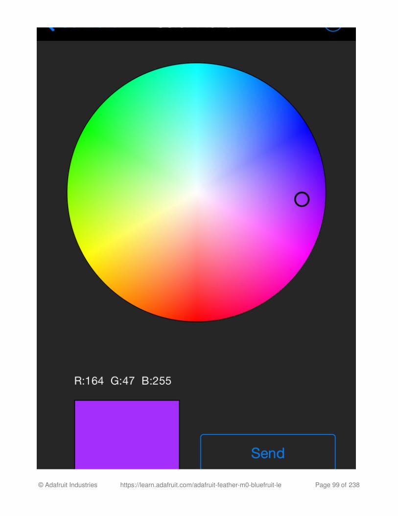
Color Picker Module
You can also send RGB color data via the Color Picker module, which presents the followingcolor selection dialogue:
Button 8 pressedButton 8 releasedButton 3 pressedButton 3 released
© Adafruit Industries https://learn.adafruit.com/adafruit-feather-m0-bluefruit-le Page 98 of 238
© Adafruit Industries https://learn.adafruit.com/adafruit-feather-m0-bluefruit-le Page 99 of 238

This will give you Hexadecimal color data in the following format:
You can combine the color picker and controller sample sketches to make color-configurable animations triggered by buttons in the mobile app-- very handy for wearables!Download this combined sample code (configured for Feather but easy to adapt to FLORA,BLE Micro, etc.) to get started:
feather_bluefruit_neopixel_animatio
n_controller.zip
https://adafru.it/kzF
RGB #A42FFF
© Adafruit Industries https://learn.adafruit.com/adafruit-feather-m0-bluefruit-le Page 100 of 238

HeartRateMonitorThe HeartRateMonitor example allows you to define a new GATT Service and associatedGATT Characteristics, and update the characteristic values using standard AT commands.
Opening the Sketch
To open the ATCommand sketch, click on the File > Examples > Adafruit_BluefruitLE_nRF51
folder in the Arduino IDE and select heartratemonitor:
This will open up a new instance of the example in the IDE, as shown below:
© Adafruit Industries https://learn.adafruit.com/adafruit-feather-m0-bluefruit-le Page 101 of 238

Configuration
Check the Configuration! page earlier to set up the sketch for Software/Hardware UART orSoftware/Hardware SPI. The default is hardware SPI
© Adafruit Industries https://learn.adafruit.com/adafruit-feather-m0-bluefruit-le Page 102 of 238

If Using Hardware or Software UART
This tutorial does not need to use the MODE pin, make sure you have the mode switch in
CMD mode if you do not configure & connect a MODE pin
This demo uses some long data transfer strings, so we recommend defining and connectingboth CTS and RTS to pins, even if you are using hardware serial.
If you are using a Flora or just dont want to connect CTS or RTS, set the pin #define's to -1
and Don't forget to also connect the CTS pin on the Bluefruit to ground! (The Flora has thisalready done)
If you are using RTS and CTS, you can remove this line below, which will slow down the datatransmission
Running the Sketch
Once you upload the sketch to your board (via the arrow-shaped upload icon), and the
upload process has finished, open up the Serial Monitor via Tools > Serial Monitor, and make
sure that the baud rate in the lower right-hand corner is set to 115200:
// this line is particularly required for Flora, but is a good idea // anyways for the super long lines ahead! ble.setInterCharWriteDelay(5); // 5 ms
© Adafruit Industries https://learn.adafruit.com/adafruit-feather-m0-bluefruit-le Page 103 of 238
© Adafruit Industries https://learn.adafruit.com/adafruit-feather-m0-bluefruit-le Page 104 of 238

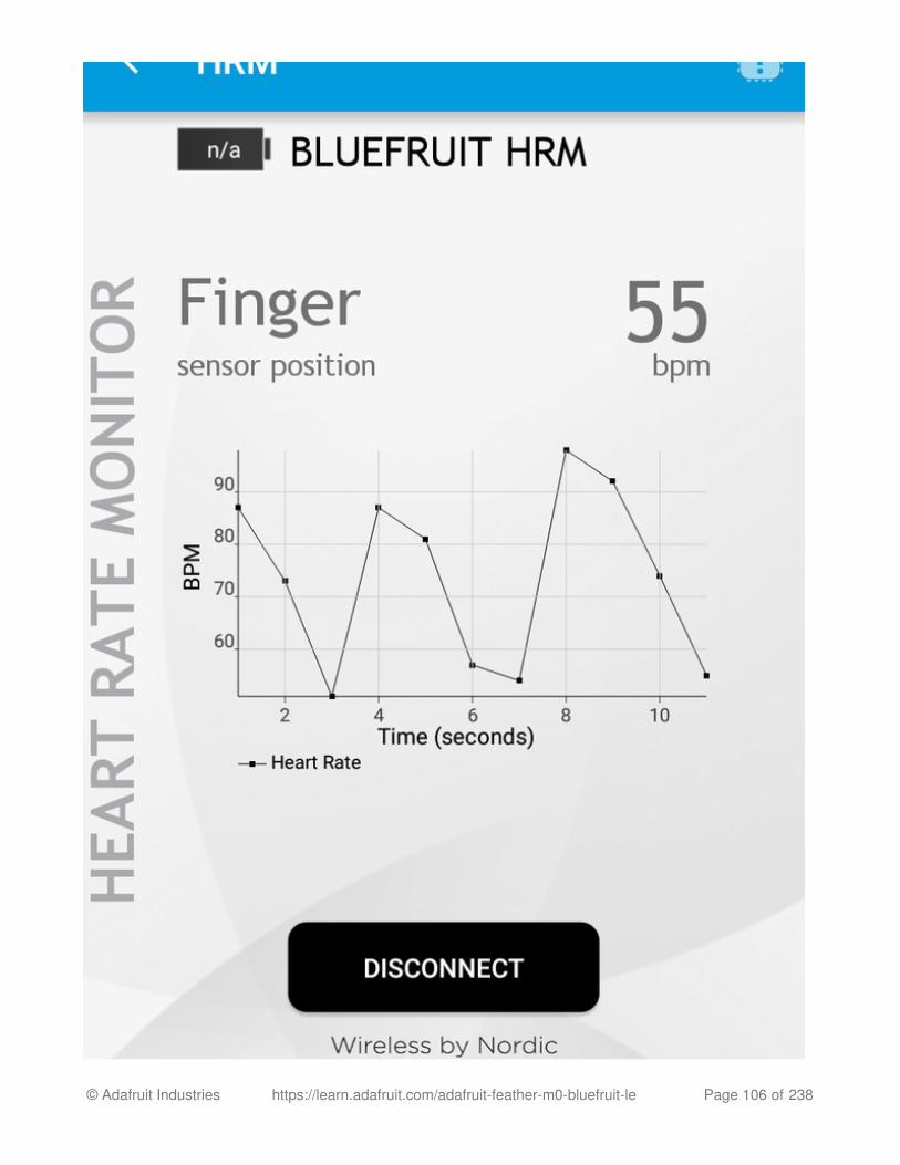
If you open up an application on your mobile device or laptop that support the standardHeart Rate Monitor Service, you should be able to see the heart rate being updated in syncwith the changes seen in the Serial Monitor:
nRF Toolbox HRM Example
The image below is a screenshot from the free nRF Toolbox application from Nordic onAndroid (also available on iOS), showing the incoming Heart Rate Monitor data:
© Adafruit Industries https://learn.adafruit.com/adafruit-feather-m0-bluefruit-le Page 105 of 238
© Adafruit Industries https://learn.adafruit.com/adafruit-feather-m0-bluefruit-le Page 106 of 238

CoreBluetooth HRM Example
The image below is from a freely available CoreBluetooth sample application from Appleshowing how to work with Bluetooth Low Energy services and characteristics:
© Adafruit Industries https://learn.adafruit.com/adafruit-feather-m0-bluefruit-le Page 107 of 238

UriBeaconThe UriBeacon example shows you how to use the built-in UriBeacon AT commands toconfigure the Bluefruit LE module as a UriBeacon advertiser, following Google's PhysicalWeb UriBeacon specification.
Opening the Sketch
To open the ATCommand sketch, click on the File > Examples > Adafruit_BluefruitLE_nRF51
folder in the Arduino IDE and select uribeacon:
This will open up a new instance of the example in the IDE, as shown below. You can edit
the URL that the beacon will point to, from the default http://www.adafruit.com or justupload as is to test
© Adafruit Industries https://learn.adafruit.com/adafruit-feather-m0-bluefruit-le Page 108 of 238

Configuration
Check the Configuration! page earlier to set up the sketch for Software/Hardware UART orSoftware/Hardware SPI. The default is hardware SPI
If using software or hardware Serial UART:
This tutorial does not need to use the MODE pin, make sure you have the mode switch
© Adafruit Industries https://learn.adafruit.com/adafruit-feather-m0-bluefruit-le Page 109 of 238

in CMD mode if you do not configure & connect a MODE pin
Don't forget to also connect the CTS pin on the Bluefruit to ground if you are not using
it! (The Flora has this already done)
Running the Sketch
Once you upload the sketch to your board (via the arrow-shaped upload icon), and the
upload process has finished, open up the Serial Monitor via Tools > Serial Monitor, and make
sure that the baud rate in the lower right-hand corner is set to 115200:
© Adafruit Industries https://learn.adafruit.com/adafruit-feather-m0-bluefruit-le Page 110 of 238

At this point you can open the Physical Web Application for Android or for iOS, and youshould see a link advertising Adafruit's website:
© Adafruit Industries https://learn.adafruit.com/adafruit-feather-m0-bluefruit-le Page 111 of 238

HALP!
When using the Bluefruit Micro or a Bluefruit LE with Flora/Due/Leonardo/Micro theexamples dont run?
We add a special line to setup() to make it so the Arduino will halt until it sees you'veconnected over the Serial console. This makes debugging great but makes it so youcannot run the program disconnected from a computer.
Solution? Once you are done debugging, remove these two lines from setup()
I can't seem to "Find" the Bluefruit LE!
Getting something like this?
For UART/Serial Bluefruits:
Check you have the MODE switch in CMD and the MODE pin not wired to anything if itisnt used!
If you are trying to control the MODE from your micro, make sure you set the MODE
while (!Serial); delay(500);
© Adafruit Industries https://learn.adafruit.com/adafruit-feather-m0-bluefruit-le Page 112 of 238

pin in the sketch
Make sure you have RXI and TXO wired right! They are often swapped by accident
Make sure CTS is tied to GND if you are using hardware serial and not using CTSCheck the MODE red LED, is it blinking? If its blinking continuously, you might be inDFU mode, power cycle the module!If you are using Hardware Serial/Software Serial make sure you know which one andhave that set up
If using SPI Bluefruit:
Make sure you have all 5 (or 6) wires connected properly.If using hardware SPI, you need to make sure you're connected to the hardware SPIport, which differs depending on the main chipset.
If using Bluefruit Micro:
Make sure you change the RESET pin to #4 in any Config file. Also be sure you areusing hardware SPI to connect!
© Adafruit Industries https://learn.adafruit.com/adafruit-feather-m0-bluefruit-le Page 113 of 238

AT CommandsThe Bluefruit LE modules use a Hayes AT-style command set to configure the device.
The advantage of an AT style command set is that it's easy to use in machine to machinecommunication, while still being somewhat user friendly for humans.
Test Command Mode '=?'
'Test' mode is used to check whether or not the specified command exists on the system ornot.
Certain firmware versions or configurations may or may not include a specific command, andyou can determine if the command is present by taking the command name and
appending '=?' to it, as shown below
If the command is present, the device will reply with 'OK'. If the command is not present, the
device will reply with 'ERROR'.
Write Command Mode '=xxx'
'Write' mode is used to assign specific value(s) to the command, such as changing the radio'stransmit power level using the command we used above.
To write a value to the command, simple append an '=' sign to the command followed by
any paramater(s) you wish to write (other than a lone '?' character which will be interprettedas tet mode):
If the write was successful, you will generally get an 'OK' response on a new line, as shownbelow:
AT+BLESTARTADV=?
AT+BLESTARTADV=?OK\r\nAT+MISSINGCMD=?ERROR\r\n
AT+BLEPOWERLEVEL=-8
© Adafruit Industries https://learn.adafruit.com/adafruit-feather-m0-bluefruit-le Page 114 of 238

If there was a problem with the command (such as an invalid parameter) you will get
an 'ERROR' response on a new line, as shown below:
Note: This particular error was generated because '3' is not a valid value for theAT+BLEPOWERLEVEL command. Entering '-4', '0' or '4' would succeed since these are allvalid values for this command.
Execute Mode
'Execute' mode will cause the specific command to 'run', if possible, and will be used whenthe command name is entered with no additional parameters.
You might use execute mode to perform a factory reset, for example, by executing theAT+FACTORYRESET command as follows:
NOTE: Many commands that are means to be read will perform the same action whetherthey are sent to the command parser in 'execute' or 'read' mode. For example, the followingcommands will produce identical results:
AT+BLEPOWERLEVEL=-8OK\r\n
AT+BLEPOWERLEVEL=3ERROR\r\n
AT+FACTORYRESET
AT+FACTORYRESETOK\r\n
AT+BLEGETPOWERLEVEL-4\r\nOK\r\nAT+BLEGETPOWERLEVEL?-4\r\nOK\r\n
© Adafruit Industries https://learn.adafruit.com/adafruit-feather-m0-bluefruit-le Page 115 of 238

If the command doesn't support execute mode, the response will normally be 'ERROR' on anew line.
Read Command Mode '?'
'Read' mode is used to read the current value of a command.
Not every command supports read mode, but you generally use this to retrieve information
like the current transmit power level for the radio by appending a '?' to the command, asshown below:
If the command doesn't support read mode or if there was a problem with the request, you
will normally get an 'ERROR' response.
If the command read was successful, you will normally get the read results followed by 'OK'on a new line, as shown below:
Note: For simple commands, 'Read' mode and 'Execute' mode behave identically.
AT+BLEPOWERLEVEL?
AT+BLEPOWERLEVEL?-4\r\nOK\r\n
© Adafruit Industries https://learn.adafruit.com/adafruit-feather-m0-bluefruit-le Page 116 of 238

Standard ATThe following standard Hayes/AT commands are available on Bluefruit LE modules:
AT
Acts as a ping to check if we are in command mode. If we are in command mode, we shouldreceive the 'OK' response.
Codebase Revision: 0.3.0
Parameters: None
Output: None
ATI
Displays basic information about the Bluefruit module.
Codebase Revision: 0.3.0
Parameters: None
Output: Displays the following values:
Board NameMicrocontroller/Radio SoC NameUnique Serial NumberCore Bluefruit Codebase RevisionProject Firmware RevisionFirmware Build DateSoftdevice, Softdevice Version, Bootloader Version (0.5.0+)
ATOK
© Adafruit Industries https://learn.adafruit.com/adafruit-feather-m0-bluefruit-le Page 117 of 238

Updates:
Version 0.4.7+ of the firmware adds the chip revision after the chip name if it can bedetected (ex. 'nRF51822 QFAAG00').
Version 0.5.0+ of the firmware adds a new 7th record containing the softdevice,softdevice version and bootloader version (ex. 'S110 7.1.0, 0.0').
ATZ
Performs a system reset.
Codebase Revision: 0.3.0
Parameters: None
Output: None
ATE
Enables or disables echo of input characters with the AT parser
Codebase Revision: 0.3.0
Parameters: '1' = enable echo, '0' = disable echo
Output: None
ATIBLEFRIENDnRF51822 QFAAG00FB462DF92A2C86560.5.00.5.0Feb 24 2015S110 7.1.0, 0.0OK
ATZOK
© Adafruit Industries https://learn.adafruit.com/adafruit-feather-m0-bluefruit-le Page 118 of 238

+++
Dynamically switches between DATA and COMMAND mode without changing the physicalCMD/UART select switch.
When you are in COMMAND mode, entering '+++\n' or '+++\r\n' will cause the module toswitch to DATA mode, and anything typed into the console will go direct to the BLUE UARTservice.
To switch from DATA mode back to COMMAND mode, simply enter '+++\n' or '+++\r\n' again(be sure to include the new line character!), and a new 'OK' response will be displayed lettingyou know that you are back in COMMAND mode (see the two 'OK' entries in the samplecode below).
Codebase Revision: 0.4.7
Parameters: None
Output: None
# Disable echo supportATE=0OK#Enable echo supportATE=1OK
Note that +++ can also be used on the mobile device to send and receive ATcommand on iOS or Android, though this should always be used with care.
See the AT+MODESWITCHEN command to control the availability of the +++command
© Adafruit Industries https://learn.adafruit.com/adafruit-feather-m0-bluefruit-le Page 119 of 238

ATIBLEFRIENDnRF51822 QFAAG00B122AAC33F3D22960.4.60.4.6Dec 22 2014OK+++OKOK
© Adafruit Industries https://learn.adafruit.com/adafruit-feather-m0-bluefruit-le Page 120 of 238

General PurposeThe following general purpose commands are available on all Bluefruit LE modules:
AT+FACTORYRESET
Clears any user config data from non-volatile memory and performs a factory reset beforeresetting the Bluefruit module.
Codebase Revision: 0.3.0
Parameters: None
Output: None
AT+DFU
Forces the module into DFU mode, allowing over the air firmware updates using a dedicatedDFU app on iOS or Android.
Codebase Revision: 0.3.0
Parameters: None
Output: None
AT+FACTORYRESETOK
As of version 0.5.0+ of the firmware, you can perform a factory reset by holding theDFU button down for 10s until the blue CONNECTED LED lights up, and thenreleasing the button.
The AT parser will no longer responsd after the AT+DFU command is entered,since normal program execution effectively halts and a full system reset isperformed to start the bootloader code
© Adafruit Industries https://learn.adafruit.com/adafruit-feather-m0-bluefruit-le Page 121 of 238

AT+HELP
Displays a comma-separated list of all AT parser commands available on the system.
Codebase Version: 0.3.0
Parameters: None
Output: A comma-separated list of all AT parser commands available on the system.
AT+NVMWRITE
Writes data to the 256 byte user non-volatile memory (NVM) region.
Codebase Version: 0.7.0
Parameters:
offset: The numeric offset for the first byte from the starting position in the user NVM
datatype: Which can be one of STRING (1), BYTEARRAY (2) or INTEGER (3)
data: The data to write to NVM memory (the exact payload format will change based onthe specified datatype).
Output: Nothing
AT+DFUOK
The sample code below may not match future firmware releases and is providedfor illustration purposes only
AT+HELPAT+FACTORYRESET,AT+DFU,ATZ,ATI,ATE,AT+DBGMEMRD,AT+DBGNVMRD,AT+HWLEDPOLARITY,AT+HWLEDOK
© Adafruit Industries https://learn.adafruit.com/adafruit-feather-m0-bluefruit-le Page 122 of 238

AT+NVMREAD
Reads data from the 256 byte user non-volatile memory (NVM) region.
Codebase Version: 0.7.0
Parameters:
offset: The numeric offset for the first byte from the starting position in the user NVM
size: The number of bytes to read
datatype: The type used for the data being read, which is required to properly parsethe data and display it as a response. The value can be one of STRING (1), BYTEARRAY(2) or INTEGER (3)
Output: The data read back, formatted based on the datatype argument.
AT+MODESWITCHEN
Enables or disables mode switches via the '+++' command on the BLE peripheral of BLEUART side of the connection.
Codebase Version: 0.7.1
Parameters:
location: This can be a string, either 'local' or 'ble' indicating which side should have the'+++' command enabled or disabled, 'local' being the Bluefruit peripheral and 'ble' beingthe phone or tablet.
state: '0' to disable '+++' mode switches, '1' to enable them.
Output: None
# Write 32768 as an integer starting at byte 16 in user NVMAT+NVMWRITE=16,INTEGER,32768OK
# Read an integer back from position 16 in user NVMAT+NVMREAD=16, 4, INTEGER32768OK
© Adafruit Industries https://learn.adafruit.com/adafruit-feather-m0-bluefruit-le Page 123 of 238

By default, '+++' is enabled locally, and disabled in BLE
# Disable reomte '+++' mode switchesAT+MODESWITCHEN=ble,0OK
© Adafruit Industries https://learn.adafruit.com/adafruit-feather-m0-bluefruit-le Page 124 of 238

HardwareThe following commands allow you to interact with the low level HW on the Bluefruit LEmodule, such as reading or toggling the GPIO pins, performing an ADC conversion ,etc.:
AT+BAUDRATE
Changes the baud rate used by the HW UART peripheral on the nRF51822.
Codebase Revision: 0.7.0
Parameters: Baud rate, which must be one of the following values:
12002400480096001440019200288003840057600768001152002304002500004608009216001000000
Output: The current baud rate
# Set the baud rate to 115200AT+BAUDRATE=115200OK
# Check the current baud rateAT+BAUDRATE115200OK
© Adafruit Industries https://learn.adafruit.com/adafruit-feather-m0-bluefruit-le Page 125 of 238

AT+HWADC
Performs an ADC conversion on the specified ADC pin
Codebase Revision: 0.3.0
Parameters: The ADC channel (0..7)
Output: The results of the ADC conversion
AT+HWGETDIETEMP
Gets the temperature in degree celcius of the BLE module's die. This can be used for debugpurposes (higher die temperature generally means higher current consumption), but doesnot corresponds to ambient temperature and can nto be used as a replacement for a normaltemperature sensor.
Codebase Revision: 0.3.0
Parameters: None
Output: The die temperature in degrees celcius
AT+HWGPIO
Gets or sets the value of the specified GPIO pin (depending on the pin's mode).
Codebase Revision: 0.3.0
Parameters: The parameters for this command change depending on the pin mode.
OUTPUT MODE: The following comma-separated parameters can be used when updating a
AT+HWADC=0178OK
AT+HWGETDIETEMP32.25OK
© Adafruit Industries https://learn.adafruit.com/adafruit-feather-m0-bluefruit-le Page 126 of 238

pin that is set as an output:
Pin numbersPin state, where:
0 = clear the pin (logic low/GND)1 = set the pin (logic high/VCC)
INPUT MODE: To read the current state of an input pin or a pin that has been configured asan output, enter the pin number as a single parameter.
Output: The pin state if you are reading an input or checking the state of an input pin(meaning only 1 parameter is supplied, the pin number), where:
0 means the pin is logic low/GND1 means the pin is logic high/VCC
Trying to set the value of a pin that has not been configured as an output willproduce an 'ERROR' response.
Some pins are reserved for specific functions on Bluefruit modules and can not beused as GPIO. If you try to make use of a reserved pin number an 'ERROR'response will be generated.
© Adafruit Industries https://learn.adafruit.com/adafruit-feather-m0-bluefruit-le Page 127 of 238

AT+HWGPIOMODE
This will set the mode for the specified GPIO pin (input, output, etc.).
Codebase Revision: 0.3.0
Parameters: This command one or two values (comma-separated in the case of twoparameters being used):
The pin numberThe new GPIO mode, where:
0 = Input1 = Output2 = Input with pullup enabled3 = Input with pulldown enabled
Output: If a single parameters is passed (the GPIO pin number) the current pin mode will bereturned.
# Set pin 14 HIGHAT+HWGPIO=14,1OK # Set pin 14 LOWAT+HWGPIO=14,0OK # Read the current state of pin 14AT+HWGPIO=140OK # Try to update a pin that is not set as an outputAT+HWGPIOMODE=14,0OKAT+HWGPIO=14,1ERROR
Some pins are reserved for specific functions on Bluefruit modules and can not beused as GPIO. If you try to make use of a reserved pin number an 'ERROR'response will be generated.
© Adafruit Industries https://learn.adafruit.com/adafruit-feather-m0-bluefruit-le Page 128 of 238

AT+HWI2CSCAN
Scans the I2C bus to try to detect any connected I2C devices, and returns the address ofdevices that were found during the scan process.
Codebase Revision: 0.3.0
Parameters: None
Output: A comma-separated list of any I2C address that were found while scanning the validaddress range on the I2C bus, or nothing is no devices were found.
AT+HWVBAT
Returns the main power supply voltage level in millivolts
Codebase Revision: 0.3.0
Parameters: None
Output: The VBAT level in millivolts
# Configure pin 14 as an outputAT+HWGPIOMODE=14,0OK
# Get the current mode for pin 14AT+HWPGIOMODE=140OK
# I2C scan with two devices detectedAT+HWI2CSCAN0x23,0x35OK
# I2C scan with no devices detectedAT+HWI2CSCANOK
© Adafruit Industries https://learn.adafruit.com/adafruit-feather-m0-bluefruit-le Page 129 of 238

AT+HWRANDOM
Generates a random 32-bit number using the HW random number generator on thenRF51822 (based on white noise).
Codebase Revision: 0.4.7
Parameters: None
Output: A random 32-bit hexadecimal value (ex. '0x12345678')
AT+HWMODELED
Allows you to override the default behaviour of the MODE led (which indicates the operatingmode by default).
Codebase Revision: 0.6.6
Parameters: LED operating mode, which can be one of the following values:
disable or DISABLE or 0 - Disable the MODE LED entirely to save power
mode or MODE or 1 - Default behaviour, indicates the current operating mode
hwuart or HWUART or 2 - Toggles the LED on any activity on the HW UART bus (TX orRX)
bleuart or BLEUART or 3 - Toggles the LED on any activity on the BLE UART Service(TX or RX characteristic)
spi or SPI or 4 - Toggles the LED on any SPI activity
manual or MANUAL or 5 - Manually sets the state of the MODE LED via a second
comma-separated parameter, which can be on, off, or toggle.
Output: If run with no parameters, returns an upper-case string representing the current
AT+HWVBAT3248OK
AT+HWRANDOM0x769ED823OK
© Adafruit Industries https://learn.adafruit.com/adafruit-feather-m0-bluefruit-le Page 130 of 238

MODE LED operating mode from the fields above
AT+UARTFLOW
Enables or disable hardware flow control (CTS + RTS) on the UART peripheral block of thenRF51822.
Codebase Revision: 0.7.0
Parameters: HW flow control state, which can be one of:
onoff01
Output: If run with no parameters, returns a number representing whether flow control isenabled (1) or disabled (0).
# Get the curent MODE LED settingAT+HWMODELEDMODEOK # Change the MODE LED to indicate BLE UART activityAT+HWMODELED=BLEUARTOK
# Manually toggle the MODE LEDAT+HWMODELED=MANUAL,TOGGLEOK
# Check the current flow control stateAT+UARTFLOW1OK
# Disable HW flow controlAT+UARTFLOW=offOK
© Adafruit Industries https://learn.adafruit.com/adafruit-feather-m0-bluefruit-le Page 131 of 238

© Adafruit Industries https://learn.adafruit.com/adafruit-feather-m0-bluefruit-le Page 132 of 238

BeaconAdafruit's Bluefruit LE modules currently support the following 'Beacon' technologies:
Beacon (Apple) via AT+BLEBEACON
UriBeacon (Google) via AT+BLEURIBEACON (deprecated)Eddystone (Google) via AT+EDDYSTONE*
Modules can be configured to act as 'Beacons' using the following commands:
AT+BLEBEACON
Codebase Revision: 0.3.0
Parameters: The following comma-separated parameters are required to enable beaconmode:
Bluetooth Manufacturer ID (uint16_t)128-bit UUIDMajor Value (uint16_t)Minor Value (uint16_t)RSSI @ 1m (int8_t)
Output: None
# Enable Apple iBeacon emulation# Manufacturer ID = 0x004CAT+BLEBEACON=0x004C,01-12-23-34-45-56-67-78-89-9A-AB-BC-CD-DE-EF-F0,0x0000,0x0000OK# Reset to change the advertising dataATZOK # Enable Nordic Beacon emulation# Manufacturer ID = 0x0059AT+BLEBEACON=0x0059,01-12-23-34-45-56-67-78-89-9A-AB-BC-CD-DE-EF-F0,0x0000,0x0000OK# Reset to change the advertising dataATZOK
© Adafruit Industries https://learn.adafruit.com/adafruit-feather-m0-bluefruit-le Page 133 of 238

Entering Nordic Beacon emulation using the sample code above, you can see the simulatedbeacon in Nordic's 'Beacon Config' tool below:
AT+BLEBEACON will cause the beacon data to be stored in non-volatile configmemory on the Bluefruit LE module, and these values will be persisted acrosssystem resets and power cycles. To remove or clear the beacon data you need toenter the 'AT+FACTORYRESET' command in command mode.
© Adafruit Industries https://learn.adafruit.com/adafruit-feather-m0-bluefruit-le Page 134 of 238

AT+BLEURIBEACON
Converts the specified URI into a UriBeacon advertising packet, and configures the moduleto advertise as a UriBeacon (part of Google's Physical Web project).
To view the UriBeacon URIs you can use one of the following mobile applications:
Android 4.3+: Physical Web on the Google Play StoreiOS: Physical Web in Apple's App Store
Codebase Revision: 0.4.7
Parameters: The URI to encode (ex. http://www.adafruit.com/blog)
Output: None of a valid URI was entered (length is acceptable, etc.).
AT+BLEURIBEACON=http://www.adafruit.com/blogOK
# Reset to change the advertising dataATZOK
© Adafruit Industries https://learn.adafruit.com/adafruit-feather-m0-bluefruit-le Page 135 of 238

If the supplied URI is too long you will get the following output:
Deprecated: AT+EDDYSTONEENABLE
This command will enable Eddystone support on the Bluefruit LE module. Eddystone supportmust be enabled before the other related commands can be used.
Codebase Revision: 0.6.6
Parameters: 1 or 0 (1 = enable, 0 = disable)
Output: The current state of Eddystone support if no parameters are provided (1 = enabled, 0= disabled)
AT+BLEURIBEACON=http://www.adafruit.com/this/uri/is/too/longURL is too longERROR
If the URI that you are trying to encode is too long, try using a shortening servicelike bit.ly, and encode the shortened URI.
UriBeacon should be considered deprecated as a standard, and EddyStone shouldbe used for any future development. No further development will happen in theBluefruit LE firmware around UriBeacon.
This command was removed in firmware 0.7.0 to avoid confusion. UseAT+EDDYSTONESERVICEEN in 0.7.0 and higher.
© Adafruit Industries https://learn.adafruit.com/adafruit-feather-m0-bluefruit-le Page 136 of 238

AT+EDDYSTONEURL
This command will set the URL for the Eddystone-URL protocol.
Codebase Revision: 0.6.6
Parameters:
The URL to encode (mandatory)An optional second parameter indicates whether to continue advertising the EddystoneURL even when the peripheral is connected to a central device
Firmware 0.6.7 added an optional third parameter for the RSSI at 0 meters value. Thisshould be measured by the end user by checking the RSSI value on the receivingdevice at 1m and then adding 41 to that value (to compensate for the signal strengthloss over 1m), so an RSSI of -62 at 1m would mean that you should enter -21 as the RSSIat 0m. Default value is -18dBm.
Output: Firmware <= 0.6.6: none. With firmware >= 0.6.7 running this command with noparameters will return the current URL.
AT+EDDYSTONECONFIGEN
This command causes the Bluefruit LE module to enable the Eddystone URL config servicefor the specified number of seconds.
# Enable Eddystone supportAT+EDDYSTONEENABLE=1OK
# Check the current Eddystone status on the moduleAT+EDDYSTONEENABLE1OK
# Set the Eddystone URL to adafruitAT+EDDYSTONEURL=http://www.adafruit.comOK # Set the Eddystone URL to adafruit and advertise it even when connectedAT+EDDYSTONEURL=http://www.adafruit.com,1OK
© Adafruit Industries https://learn.adafruit.com/adafruit-feather-m0-bluefruit-le Page 137 of 238

This command should be used in combination with the Physical Web application fromGoogle, available for Android or iOS. Run this command then select the 'Edit URL' optionfrom the app to change the destination URL over the air.
Codebase Revision: 0.6.6
Parameters: The number of seconds to advertised the config service UUID
Output: None
AT+EDDYSTONESERVICEEN
Adds or removes the Eddystone service from the GATT table (requires a reset to take effect).
Codebase Revision: 0.7.0
Parameters: Whether or not the Eddystone service should be enabled or not, using on of thefollowing values:
onoff10
Output: If the command is executed with no parameters it will disable a numeric valueindicating whether the service is enabled (1) or disabled (0).
# Start advertising the Eddystone config service for 5 minutes (300s)AT+EDDYSTONECONFIGEN=300OK
You must perform a system reset for this command to take effect.
© Adafruit Industries https://learn.adafruit.com/adafruit-feather-m0-bluefruit-le Page 138 of 238

AT+EDDYSTONEBROADCAST
This command can be used to start of stop advertising the Eddystone payload using the URLstored in non-volatile memory (NVM).
Codebase Revision: 0.7.0
Parameters: Whether or not the payload should be broadcast, using one of the followingvalues:
onoff10
Output: If executed with no parameters, the current broadcast state will be displayed as anumeric value.
# Enable Eddystone serviceAT+EddyStonServiceEn=onOK
AT+EddyStonServiceEn=1OK
# Disable Eddystone serviceAT+EddyStonServiceEn=offOK
AT+EddyStonServiceEn=0OK
© Adafruit Industries https://learn.adafruit.com/adafruit-feather-m0-bluefruit-le Page 139 of 238

# Enable broadcasting current setting of EddyStone (stored previously on nvm)AT+EddyStoneBroadcast=onOK
AT+EddyStoneBroadcast=1OK # Disable broadcasting current setting of EddyStone (still stored on nvm)AT+EddyStoneBroadcast=offOK
AT+EddyStoneBroadcast=0OK
© Adafruit Industries https://learn.adafruit.com/adafruit-feather-m0-bluefruit-le Page 140 of 238

BLE GenericThe following general purpose BLE commands are available on Bluefruit LE modules:
AT+BLEPOWERLEVEL
Gets or sets the current transmit power level for the module's radio (higher transmit powerequals better range, lower transmit power equals better battery life).
Codebase Revision: 0.3.0
Parameters: The TX power level (in dBm), which can be one of the following values (fromlowest to higher transmit power):
-40-20-16-12-8-404
Output: The current transmit power level (in dBm)
The updated power level will take affect as soon as the command is entered. If thedevice isn't connected to another device, advertising will stop momentarily andthen restart once the new power level has taken affect.
© Adafruit Industries https://learn.adafruit.com/adafruit-feather-m0-bluefruit-le Page 141 of 238

AT+BLEGETADDRTYPE
Gets the address type (for the 48-bit BLE device address).
Normally this will be '1' (random), which means that the module uses a 48-bit address thatwas randomly generated during the manufacturing process and written to the die by themanufacturer.
Random does not mean that the device address is randomly generated every time, only thata one-time random number is used.
Codebase Revision: 0.3.0
Parameters: None
Output: The address type, which can be one of the following values:
0 = public1 = random
# Get the current TX power level (in dBm)AT+BLEPOWERLEVEL0OK # Set the TX power level to 4dBm (maximum value)AT+BLEPOWERLEVEL=4OK # Set the TX power level to -12dBm (better battery life)AT+BLEPOWERLEVEL=-12OK # Set the TX power level to an invalid valueAT+BLEPOWERLEVEL=-3ERROR
AT+BLEGETADDRTYPE1OK
© Adafruit Industries https://learn.adafruit.com/adafruit-feather-m0-bluefruit-le Page 142 of 238

AT+BLEGETADDR
Gets the 48-bit BLE device address.
Codebase Revision: 0.3.0
Parameters: None
Output: The 48-bit BLE device address in the following format: 'AA:BB:CC:DD:EE:FF'
AT+BLEGETPEERADDR
Gets the 48-bit address of the peer (central) device we are connected to.
Codebase Revision: 0.6.5
Parameters: None
Output: The 48-bit address of the connected central device in hex format. The command will
return ERROR if we are not connected to a central device.
AT+BLEGETRSSI
Gets the RSSI value (Received Signal Strength Indicator), which can be used to estimate thereliability of data transmission between two devices (the lower the number the better).
AT+BLEGETADDRE4:C6:C7:31:95:11OK
Please note that the address returned by the central device is almost always arandom value that will change over time, and this value should generally not betrusted. This command is provided for certain edge cases, but is not useful in mostday to day scenarios.
AT+BLEGETPEERADDR48:B2:26:E6:C1:1DOK
© Adafruit Industries https://learn.adafruit.com/adafruit-feather-m0-bluefruit-le Page 143 of 238

Codebase Revision: 0.3.0
Parameters: None
Output: The RSSI level (in dBm) if we are connected to a device, otherwise '0'
# Connected to an external deviceAT+BLEGETRSSI-46OK # Not connected to an external deviceAT+BLEGETRSSI0OK
© Adafruit Industries https://learn.adafruit.com/adafruit-feather-m0-bluefruit-le Page 144 of 238

BLE ServicesThe following commands allow you to interact with various GATT services present onBluefruit LE modules when running in Command Mode.
AT+BLEUARTTX
This command will transmit the specified text message out via the UART Service while youare running in Command Mode.
Codebase Revision: 0.3.0
Parameters: The message payload to transmit. The payload can be up to 240 characters(since AT command strings are limited to a maximum of 256 bytes total).
Output: This command will produce an ERROR message if you are not connected to acentral device, or if the internal TX FIFO on the Bluefruit LE module is full.
As of firmware release 0.6.2 and higher, AT+BLEUARTTX can accept a limited set of escapecode sequences:
\r = carriage return\n = new line\t = tab\b = backspace\\ = backward slash
As of firmware release 0.6.7 and higher, AT+BLEUARTTX can accept the following escapecode sequence since AT+BLEUARTTX=? has a specific meaning to the AT parser:
\? = transmits a single question mark
As of firmware release 0.7.6 and higher, AT+BLEUARTTX can accept the following escapecode sequence:
\+ = transmit a single '+' character without having to worry about `+++` mode switchcombinations
ESCAPE SEQUENCE NOTE: If you are trying to send escape sequences in code viasomething like 'ble.print("...");' please note that you will need to send a double
© Adafruit Industries https://learn.adafruit.com/adafruit-feather-m0-bluefruit-le Page 145 of 238

TX FIFO Buffer Handling
Starting with firmware version 0.6.7, when the TX FIFO buffer is full a 200ms blocking delaywill be used to see if any free space becomes available in the FIFO before returning ERROR.The exact process is detailed in the flow chart below:
back-slash for the escape code to arrive as-intended in the AT command. Forexample: ble.println("AT+BLEUARTTX=Some Test\\r\\n");
You must be connected to another device for this command to execute
# Send a string when connected to another deviceAT+BLEUARTTX=THIS IS A TESTOK # Send a string when not connectedAT+BLEUARTTX=THIS IS A TESTERROR
© Adafruit Industries https://learn.adafruit.com/adafruit-feather-m0-bluefruit-le Page 146 of 238

You can use the AT+BLEUARTFIFO=TX command to check the size of the TX FIFO beforesending data to ensure that you have enough free space available in the buffer.
The TX FIFO has the following size, depending on the firmware version used:
Firmware <=0.6.6: 160 characters wide
Firmware >=0.6.7: 1024 characters wide
Note: The TX FIFO full check will happen for each GATT transaction (of up to 20bytes of data each), so large data transfers may have multiple 200ms wait states.
It IS possible with large data transfers that part of the payload can be transmitted,and the command can still produce an ERROR if the FIFO doesn't empty in time inthe middle of the payload transfer (since data is transmitted in maximum 20 bytechunks). If you need to ensure reliable data transfer, you should always check the
© Adafruit Industries https://learn.adafruit.com/adafruit-feather-m0-bluefruit-le Page 147 of 238

AT+BLEUARTTXF
This is a convenience function the serves the same purpose as AT+BLEUARTTX, but datais immediately sent in a single BLE packet ('F' for force packet). This command will accept a
maximum of 20 characters, which is the limit of what can be send in a single packet.
Codebase Revision: 0.7.6
Parameters: See AT+BLEUARTTX
Output: See AT+BLEUARTTX
AT+BLEUARTRX
This command will dump the UART service's RX buffer to the display if any data has beenreceived from from the UART service while running in Command Mode. The data will beremoved from the buffer once it is displayed using this command.
Any characters left in the buffer when switching back to Data Mode will cause the bufferedcharacters to be displayed as soon as the mode switch is complete (within the limits ofavailable buffer space, which is 1024 bytes on current black 32KB SRAM devices, or 160bytes for the blue first generation BLEFriend board based on 16KB SRAM parts).
Codebase Revision: 0.3.0
Parameters: None
Output: The RX buffer's content if any data is available, otherwise nothing.
TX FIFO size before sending data, which you can do using the AT+BLEUARTFIFOcommand. If not enough space is available for the entire payload, add a SW delayuntil enough space is available. Any single AT+BLEUARTTX command can fit intothe FIFO, but multiple large instances of this command may cause the FIFO to fillup mid transfer.
You can also use the AT+BLEUARTFIFO=RX command to check if any incomingdata is available or not.
© Adafruit Industries https://learn.adafruit.com/adafruit-feather-m0-bluefruit-le Page 148 of 238

AT+BLEUARTFIFO
This command will return the free space available in the BLE UART TX and RX FIFOs. If youare transmitting large chunks of data, you may want to check if you have enough free spacein the TX FIFO before sending, keeping in mind that individual GATT packets can contain upto 20 user bytes each.
Codebase Revision: 0.6.7
Parameters: Running this command with no parameters will return two comma-separatedvalues indicating the free space in the TX buffer, following by the RX buffer. To request aspecific buffer, you can execute the command with either a "TX" or "RX" value (For example:"AT+BLEUARTFIFO=TX").
Output: The free space remaining in the TX and RX FIFO buffer if no parameter is present,otherwise the free space remaining in the specified FIFO buffer.
AT+BLEKEYBOARDEN
This command will enable GATT over HID (GoH) keyboard support, which allows you to
# Command results when data is availableAT+BLEUARTRXSent from AndroidOK # Command results when no data is availableAT+BLEUARTRXOK
AT+BLEUARTFIFO1024,1024OK
AT+BLEUARTFIFO=TX1024OK
AT+BLEUARTFIFO=RX1024OK
© Adafruit Industries https://learn.adafruit.com/adafruit-feather-m0-bluefruit-le Page 149 of 238

emulate a keyboard on supported iOS and Android devices. By default HID keyboardsupport is disabled, so you need to set BLEKEYBOARDEN to 1 and then perform a systemreset before the keyboard will be enumerated and appear in the Bluetooth preferences onyour phone, where if can be bonded as a BLE keyboard.
Codebase Revision: 0.5.0
Parameters: 1 or 0 (1 = enable, 0 = disable)
Output: None
AT+BLEKEYBOARD
Sends text data over the BLE keyboard interface (if it has previously been enabled viaAT+BLEKEYBOARDEN).
Any valid alpha-numeric character can be sent, and the following escape sequences are alsosupported:
As of firmware version 0.6.6 this command is now an alias for AT+BLEHIDEN
You must perform a system reset (ATZ) before the changes take effect!
Before you can use your HID over GATT keyboard, you will need to bond yourmobile device with the Bluefruit LE module in the Bluetooth preferences panel.
# Enable BLE keyboard support then resetAT+BLEKEYBOARDEN=1OKATZOK # Disable BLE keyboard support then resetAT+BLEKEYBOARDEN=0OKATZOK
© Adafruit Industries https://learn.adafruit.com/adafruit-feather-m0-bluefruit-le Page 150 of 238

\r - Carriage Return\n - Line Feed\b - Backspace\t - Tab\\ - Backslash
As of version 0.6.7 you can also use the following escape code when sending a singlecharacter ('AT+BLEKEYBOARD=?' has another meaning for the AT parser):
\? - Question mark
Codebase Revision: 0.5.0
Parameters: The text string (optionally including escape characters) to transmit
Output: None
AT+BLEKEYBOARDCODE
Sends a raw hex sequence of USB HID keycodes to the BLE keyboard interface includingkey modifiers and up to six alpha-numeric characters.
This command accepts the following ascii-encoded HEX payload, matching the way HID overGATT sends keyboard data:
Byte 0: Modifier
Byte 1: Reserved (should always be 00)
Bytes 2..7: Hexadecimal values for ASCII-encoded characters (if no character is usedyou can enter '00' or leave trailing characters empty)
After a keycode sequence is sent with the AT+BLEKEYBOARDCODE command, you must
send a second AT+BLEKEYBOARDCODE command with at least two 00 characters to
# Send a URI with a new line ending to execute in Chrome, etc.AT+BLEKEYBOARD=http://www.adafruit.com\r\nOK # Send a single question mark (special use case, 0.6.7+)AT+BLEKEYBOARD=\?OK
© Adafruit Industries https://learn.adafruit.com/adafruit-feather-m0-bluefruit-le Page 151 of 238

indicate the keys were released!
Modifier Values
The modifier byte can have one or more of the following bits set:
Bit 0 (0x01): Left Control
Bit 1 (0x02): Left Shift
Bit 2 (0x04): Left Alt
Bit 3 (0x08): Left Window
Bit 4 (0x10): Right Control
Bit 5 (0x20): Right Shift
Bit 6 (0x40): Right Alt
Bit 7 (0x80): Right Window
Codebase Revision: 0.5.0
Parameters: A set of hexadecimal values separated by a hyphen ('-'). Note that these areHID scan code values, not standard ASCII values!
Output: None
A list of HID keyboard codes can be found here (see section 7).
AT+BLEHIDEN
This command will enable GATT over HID (GoH) support, which allows you to emulate a
HID key code values don't correspond to ASCII key codes! For example, 'a' has anHID keycode value of '04', and there is no keycode for an upper case 'A' since youuse the modifier to set upper case values. For details, google 'usb hid keyboardscan codes', and see the example below.
# send 'abc' with shift key --> 'ABC'AT+BLEKEYBOARDCODE=02-00-04-05-06-00-00OK# Indicate that the keys were released (mandatory!)AT+BLEKEYBOARDCODE=00-00OK
© Adafruit Industries https://learn.adafruit.com/adafruit-feather-m0-bluefruit-le Page 152 of 238

keyboard, mouse or media controll on supported iOS, Android, OSX and Windows 10devices. By default HID support is disabled, so you need to set BLEHIDEN to 1 and thenperform a system reset before the HID devices will be enumerated and appear in on yourcentral device.
Codebase Revision: 0.6.6
Parameters: 1 or 0 (1 = enable, 0 = disable)
Output: None
AT+BLEHIDMOUSEMOVE
Moves the HID mouse or scroll wheen position the specified number of ticks.
All parameters are signed 8-bit values (-128 to +127). Positive values move to the right ordown, and origin is the top left corner.
Codebase Revision: 0.6.6
Parameters: X Ticks (+/-), Y Ticks (+/-), Scroll Wheel (+/-), Pan Wheel (+/-)
Output: None
You normally need to 'bond' the Bluefruit LE peripheral to use the HID commands,and the exact bonding process will change from one operating system to another.
If you have previously bonded to a device and need to clear the bond, you can runthe AT+FACTORYRESET command which will erase all stored bond data on theBluefruit LE module.
# Enable GATT over HID support on the Bluefruit LE moduleAT+BLEHIDEN=1OK # Reset so that the changes take effectATZOK
© Adafruit Industries https://learn.adafruit.com/adafruit-feather-m0-bluefruit-le Page 153 of 238

AT+BLEHIDMOUSEBUTTON
Manipulates the HID mouse buttons via the specific string(s).
Codebase Revision: 0.6.6
Parameters: Button Mask String [L][R][M][B][F], Action [PRESS][CLICK][DOUBLECLICK][HOLD]
L = Left ButtonR = Right ButtonM = Middle ButtonB = Back ButtonF = Forward ButtonIf the second parameter (Action) is "HOLD", an optional third parameter can be passedspecifying how long the button should be held in milliseconds.
Output: None
# Move the mouse 100 ticks right and 100 ticks downAT+BLEHIDMOUSEMOVE=100,100OK # Scroll down 20 pixels or lines (depending on context)AT+BLEHIDMOUSEMOVE=,,20,OK # Pan (horizontal scroll) to the right (exact behaviour depends on OS)AT+BLEHIDMOUSEMOVE=0,0,0,100
© Adafruit Industries https://learn.adafruit.com/adafruit-feather-m0-bluefruit-le Page 154 of 238

AT+BLEHIDCONTROLKEY
Sends HID media control commands for the bonded device (adjust volume, screenbrightness, song selection, etc.).
Codebase Revision: 0.6.6
Parameters: The HID control key to send, followed by an optional delay in ms to hold thebutton
The control key string can be one of the following values:
System Controls (works on most systems)
BRIGHTNESS+BRIGHTNESS-
Media Controls (works on most systems)
PLAYPAUSEMEDIANEXTMEDIAPREVIOUSMEDIASTOP
Sound Controls (works on most systems)
VOLUME
# Double click the left mouse buttonAT+BLEHIDMOUSEBUTTON=L,doubleclickOK
# Press the left mouse button down, move the mouse, then release L# This is required to perform 'drag' then stop type operationsAT+BLEHIDMOUSEBUTTON=LOKAT+BLEHIDMOUSEMOVE=-100,50OKAT+BLEHIDMOUSEBUTTON=0OK # Hold the backward mouse button for 200 milliseconds (OS dependent)AT+BLEHIDMOUSEBUTTON=B,hold,200OK
© Adafruit Industries https://learn.adafruit.com/adafruit-feather-m0-bluefruit-le Page 155 of 238

MUTEBASSTREBLEBASS_BOOSTVOLUME+VOLUME-BASS+BASS-TREBLE+TREBLE-
Application Launchers (Windows 10 only so far)
EMAILREADERCALCULATORFILEBROWSER
Browser/File Explorer Controls (Firefox on Windows/Android only)
SEARCHHOMEBACKFORWARDSTOPREFRESHBOOKMARKS
You can also send a raw 16-bit hexadecimal value in the '0xABCD' format. A full list of 16-bit'HID Consumer Control Key Codes' can be found here (see section 12).
Output: Normally none.
If you are not bonded and connected to a central device, this command will returnERROR. Make sure you are connected and HID support is enabled before runningthese commands.
© Adafruit Industries https://learn.adafruit.com/adafruit-feather-m0-bluefruit-le Page 156 of 238

AT+BLEHIDGAMEPADEN
Enables HID gamepad support in the HID service. By default the gamepad is disabled as ofversion 0.7.6 of the firmware since it causes problems on iOS and OS X and should only beused on Android and Windows based devices.
Codebase Revision: 0.7.6
Parameters: Whether the gamepad service should be enabled via one of the followingvalues:
onoff10
Output: If executed with no parameters, a numeric value will be returned indicating whetherthe battery service is enabled (1) or disabled (0).
AT+BLEHIDGAMEPAD
Sends a specific HID gamepad payload out over BLE
Codebase Revision: 0.7.0
Parameters: The following comma-separated parameters are available:
# Toggle the sound on the bonded central deviceAT+BLEHIDCONTROLKEY=MUTEOK
# Hold the VOLUME+ key for 500msAT+BLEHIDCONTROLKEY=VOLUME+,500OK
# Send a raw 16-bit Consumer Key Code (0x006F = Brightness+)AT+BLEHIDCONTROLKEY=0x006FOK
This command requires a system reset to take effect.
© Adafruit Industries https://learn.adafruit.com/adafruit-feather-m0-bluefruit-le Page 157 of 238

x: LEFT, RIGHT: If X=-1 then 'LEFT' is pressed, if X=1 then 'RIGHT' is pressed, if X=0 thenneither left nor right are pressed
y: UP, DOWN: If Y=-1 then 'UP' is pressed, if Y=1 then 'DOWN' is pressed, if Y=0 thenneither up nor down are pressed
buttons: 0x00-0xFF, which is a bit mask for 8 button 0-7
Output: Nothing
AT+BLEMIDIEN
Enables or disables the BLE MIDI service.
Codebase Revision: 0.7.0
Parameters: State, which can be one of:
onoff01
Output: If executed with no parameters, it will return the current state of the MIDI service asan integer indicating if it is enabled (1) or disabled (0).
HID gamepad is disabled by default as of version 0.7.6, and must first be enabledvia AT+BLEHIDGAMEPADEN=1 before it can be used.
Note: You need to send both 'press' and 'release' events for each button, otherwisethe system will think that the button is still pressed until a release state is received.
# Press 'RIGHT' and 'Button0' at the same timeAT+BLEHIDGAMEPAD=1,0,0x01
# Press 'UP' and 'Button1' + 'Button0' at the same timeAT+BLEHIDGAMEPAD=0,-1,0x03
© Adafruit Industries https://learn.adafruit.com/adafruit-feather-m0-bluefruit-le Page 158 of 238

AT+BLEMIDIRX
Reads an incoming MIDI character array from the buffer.
Codebase Revision: 0.7.0
Parameters: None
Output: The midi event in byte array format
AT+BLEMIDITX
Sends a MIDI event to host.
Codebase Revision: 0.7.0
Parameters: The MIDI event in hex array format, which can be either:
A series of full MIDI events (up to 4 events)Exactly 1 full MIDI event + several running events without status (up to 7)
Output: None
Note: This command will require a reset to take effect.
# Check the current state of the MIDI serviceAT+BLEMIDIEN1OK
# Enable the MIDI ServiceAT+BLEMIDIEN=1OK
AT+BLEMIDIRX90-3C-7FOK
© Adafruit Industries https://learn.adafruit.com/adafruit-feather-m0-bluefruit-le Page 159 of 238

AT+BLEBATTEN
Enables the Battery Service following the definition from the Bluetooth SIG.
Codebase Revision: 0.7.0
Parameters: Whether the battery service should be enabled, via on of the following values:
onoff10
Output: If executed with no parameters, a numeric value will be returned indicating whetherthe battery service is enabled (1) or disabled (0).
AT+BLEBATTVAL
Sets the current battery level in percentage (0..100) for the Battery Service (if enabled).
Codebase Revision: 0.7.0
# Send 1 event (middle C with max velocity)AT+BLEMIDITX=90-3C-7FOK
# Send 2 eventsAT+BLEMIDITX=90-3C-7F-A0-3C-7FOK
# Send 1 full event + running eventAT+BLEMIDITX=90-3C-7F-3C-7FOK
This command requires a system reset to take effect.
# Enable the Battery ServiceAT+BLEBATTEN=1OK
© Adafruit Industries https://learn.adafruit.com/adafruit-feather-m0-bluefruit-le Page 160 of 238

Parameters: The percentage for the battery in the range of 0..100.
Output: If executed with no parameters, the current battery level stored in the characteristic.
# Set the battery level to 72%AT+BLEBATTVAL=72OK
© Adafruit Industries https://learn.adafruit.com/adafruit-feather-m0-bluefruit-le Page 161 of 238

BLE GAPGAP, which stands for the Generic Access Profile, governs advertising and connections withBluetooth Low Energy devices.
The following commands can be used to configure the GAP settings on the BLE module.
You can use these commands to modify the advertising data (for ex. the device name thatappears during the advertising process), to retrieve information about the connection thathas been established between two devices, or the disconnect if you no longer wish tomaintain a connection.
AT+GAPCONNECTABLE
This command can be used to prevent the device from being 'connectable'.
Codebase Revision: 0.7.0
Parameters: Whether or not the device should advertise itself as connectable, using one ofthe following values:
yesno10
Output: The 'connectable' state of the device if no parameter is provided
AT+GAPGETCONN
Diplays the current connection status (if we are connected to another BLE device or not).
# Make the device non-connectable (advertising only)AT+GAPCONNECTABLE=0OK
# Check the current connectability statusAT+GAPCONNECTABLE1OK
© Adafruit Industries https://learn.adafruit.com/adafruit-feather-m0-bluefruit-le Page 162 of 238

Codebase Revision: 0.3.0
Parameters: None
Output: 1 if we are connected, otherwise 0
AT+GAPDISCONNECT
Disconnects to the external device if we are currently connected.
Codebase Revision: 0.3.0
Parameters: None
Output: None
AT+GAPDEVNAME
Gets or sets the device name, which is included in the advertising payload for the BluefruitLE module
Codebase Revision: 0.3.0
Parameters:
None to read the current device nameThe new device name if you want to change the value
# ConnectedAT+GAPGETCONN1OK # Not connectedAT+GAPGETCONN0OK
AT+GAPDISCONNECTOK
© Adafruit Industries https://learn.adafruit.com/adafruit-feather-m0-bluefruit-le Page 163 of 238

Output: The device name if the command is executed in read mode
AT+GAPDELBONDS
Deletes and bonding information stored on the Bluefruit LE module.
Codebase Revision: 0.3.0
Parameters: None
Output: None
AT+GAPINTERVALS
Gets or sets the various advertising and connection intervals for the Bluefruit LE module.
Be extremely careful with this command since it can be easy to cause problems changing theintervals, and depending on the values selected some mobile devices may no longerrecognize the module or refuse to connect to it.
Updating the device name will persist the new value to non-volatile memory, andthe updated name will be used when the device is reset. To reset the device tofactory settings and clean the config data from memory run theAT+FACTORYRESET command.
# Read the current device nameAT+GAPDEVNAMEUARTOK # Update the device name to 'BLEFriend'AT+GAPDEVNAME=BLEFriendOK# Reset to take effectATZOK
AT+GAPDELBONDSOK
© Adafruit Industries https://learn.adafruit.com/adafruit-feather-m0-bluefruit-le Page 164 of 238

Codebase Revision: 0.3.0
Parameters: If updating the GAP intervals, the following comma-separated values can beentered:
Minimum connection interval (in milliseconds)Maximum connection interval (in milliseconds)Fast Advertising interval (in milliseconds)Fast Advertising timeout (in seconds)>= 0.7.0: Low power advertising interval (in milliseconds), default = 417.5 ms
Please note the following min and max limitations for the GAP parameters:
Absolute minimum connection interval: 10ms
Absolute maximum connection interval: 4000ms
Absolute minimum fast advertising interval: 20ms
Absolute maximum fast advertisting interval: 10240ms
Absolute minimum low power advertising interval: 20ms
Absolute maximum low power advertising interval: 10240ms
Output: If reading the current GAP interval settings, the following comma-separatedinformation will be displayed:
Minimum connection interval (in milliseconds)Maximum connection interval (in milliseconds)Advertising interval (in milliseconds)Advertising timeout (in milliseconds)
To save power, the Bluefruit modules automatically drop to a lower advertising rateafter 'fast advertising timeout' seconds. The default value is 30 seconds ('FastAdvertising Timeout'). The low power advertising interval is hard-coded toapproximately 0.6s in firmware < 0.7.0. Support to control the low power intervalwas added in the 0.7.0 firmware release via an optional fifth parameter.
If you only wish to update one interval value, leave the other comma-separatedvalues empty (ex. ',,110,' will only update the third value, advertising interval).
© Adafruit Industries https://learn.adafruit.com/adafruit-feather-m0-bluefruit-le Page 165 of 238

AT+GAPSTARTADV
Causes the Bluefruit LE module to start transmitting advertising packets if this isn't alreadythe case (assuming we aren't already connected to an external device).
Codebase Revision: 0.3.0
Parameters: None
Output: None
Updating the GAP intervals will persist the new values to non-volatile memory, andthe updated values will be used when the device is reset. To reset the device tofactory settings and clean the config data from memory run theAT+FACTORYRESET command.
# Read the current GAP intervalsAT+GAPINTERVALS20,100,100,30 # Update all valuesAT+GAPINTERVALS=20,200,200,30OK # Update only the advertising intervalAT+GAPINTERVALS=,,150,OK
# Command results when advertising data is not being sentAT+GAPSTARTADVOK # Command results when we are already advertisingAT+GAPSTARTADVERROR # Command results when we are connected to another deviceAT+GAPSTARTADVERROR
© Adafruit Industries https://learn.adafruit.com/adafruit-feather-m0-bluefruit-le Page 166 of 238

AT+GAPSTOPADV
Stops advertising packets from being transmitted by the Bluefruit LE module.
Codebase Revision: 0.3.0
Parameters: None
Output: None
AT+GAPSETADVDATA
Sets the raw advertising data payload to the specified byte array (overriding the normaladvertising data), following the guidelines in the Bluetooth 4.0 or 4.1 Core Specification.
In particular, Core Specification Supplement (CSS) v4 contains the details on commonadvertising data fields like 'Flags' (Part A, Section 1.3) and the various Service UUID lists (PartA, Section 1.1). A list of all possible GAP Data Types is available on the Bluetooth SIG'sGeneric Access Profile page.
The Advertising Data payload consists of Generic Access Profile data that is inserted into theadvertising packet in the following format: [U8:LEN] [U8:Data Type Value] [n:Value]
AT+GAPSTOPADVOK
WARNING: This command requires a degree of knowledge about the low leveldetails of the Bluetooth 4.0 or 4.1 Core Specification, and should only be used byexpert users. Misuse of this command can easily cause your device to beundetectable by central devices in radio range.
WARNING: This command will override the normal advertising payload and mayprevent some services from acting as expected.
To restore the advertising data to the normal default values use theAT+FACTORYRESET command.
© Adafruit Industries https://learn.adafruit.com/adafruit-feather-m0-bluefruit-le Page 167 of 238

For example, to insert the 'Flags' Data Type (Data Type Value 0x01), and set the value to0x06/0b00000110 (BR/EDR Not Supported and LE General Discoverable Mode) we woulduse the following byte array:
0x02 indicates the number of bytes in the entry
0x01 is the 'Data Type Value' and indicates that this is a 'Flag'0x06 (0b00000110) is the Flag value, and asserts the following fields (see CoreSpecification 4.0, Volume 3, Part C, 18.1):
LE General Discoverable Mode (i.e. anyone can discover this device)
BR/EDR Not Supported (i.e. this is a Bluetooth Low Energy only device)
If we also want to include two 16-bit service UUIDs in the advertising data (so that listeningdevices know that we support these services) we could append the following data to thebyte array:
0x05 indicates that the number of bytes in the entry (5)
0x02 is the 'Data Type Value' and indicates that this is an 'Incomplete List of 16-bit
Service Class UUIDs'
0x0D 0x18 is the first 16-bit UUID (which translates to 0x180D, corresponding to theHeart Rate Service).
0x0A 0x18 is another 16-bit UUID (which translates to 0x180A, corresponding to theDevice Information Service).
Codebase Revision: 0.3.0
Parameters: The raw byte array that should be inserted into the advertising data section of
02-01-06
05-02-0D-18-0A-18
Including the service UUIDs is important since some mobile applications will onlywork with devices that advertise a specific service UUID in the advertising packet.This is true for most apps from Nordic Semiconductors, for example.
© Adafruit Industries https://learn.adafruit.com/adafruit-feather-m0-bluefruit-le Page 168 of 238

the advertising packet, being careful to stay within the space limits defined by the BluetoothCore Specification.
Response: None
The results of this command can be seen in the screenshot below, taken from a snifferanalyzing the advertising packets in Wireshark. The advertising data payload is higlighted inblue in the raw byte array at the bottom of the image, and the packet analysis is in the uppersection:
# Advertise as Discoverable and BLE only with 16-bit UUIDs 0x180D and 0x180AAT+GAPSETADVDATA=02-01-06-05-02-0d-18-0a-18OK
© Adafruit Industries https://learn.adafruit.com/adafruit-feather-m0-bluefruit-le Page 169 of 238

BLE GATTGATT, which standards for the Generic ATTribute Profile, governs data organization and dataexchanges between connected devices. One device (the peripheral) acts as a GATT Server,which stores data in Attribute records, and the second device in the connection (the central)acts as a GATT Client, requesting data from the server whenever necessary.
The following commands can be used to create custom GATT services and characteristics onthe BLEFriend, which are used to store and exchange data.
Please note that any characteristics that you define here will automatically be saved to non-volatile FLASH config memory on the device and re-initialised the next time the device starts.
GATT Limitations
The commands below have the following limitations due to SRAM and resource availability,which should be kept in mind when creating or working with customer GATT services andcharacteristics.
These values apply to firmware 0.7.0 and higher:
Maximum number of services: 10Maximum number of characteristics: 30Maximum buffer size for each characteristic: 32 bytesMaximum number of CCCDs: 16
If you want to clear any previous config value, enter the 'AT+FACTORYRESET' commandbefore working on a new peripheral configuration.
AT+GATTCLEAR
Clears any custom GATT services and characteristics that have been defined on the device.
Codebase Revision: 0.3.0
Parameters: None
You need to perform a system reset via 'ATZ' before most of the commands belowwill take effect!
© Adafruit Industries https://learn.adafruit.com/adafruit-feather-m0-bluefruit-le Page 170 of 238

Response: None
AT+GATTADDSERVICE
Adds a new custom service definition to the device.
Codebase Revision: 0.3.0
Parameters: This command accepts a set of comma-separated key-value pairs that are usedto define the service properties. The following key-value pairs can be used:
UUID: The 16-bit UUID to use for this service. 16-bit values should be in hexadecimalformat (0x1234).
UUID128: The 128-bit UUID to use for this service. 128-bit values should be in thefollowing format: 00-11-22-33-44-55-66-77-88-99-AA-BB-CC-DD-EE-FF
Response: The index value of the service in the custom GATT service lookup table. (It'simportant to keep track of these index values to work with the service later.)
AT+GATTCLEAROK
Note: Key values are not case-sensitive
Only one UUID type can be entered for the service (either UUID or UUID128)
© Adafruit Industries https://learn.adafruit.com/adafruit-feather-m0-bluefruit-le Page 171 of 238

AT+GATTADDCHAR
Adds a custom characteristic to the last service that was added to the peripheral (viaAT+GATTADDSERVICE).
# Clear any previous custom services/characteristicsAT+GATTCLEAROK
# Add a battery service (UUID = 0x180F) to the peripheralAT+GATTADDSERVICE=UUID=0x180F1OK # Add a battery measurement characteristic (UUID = 0x2A19), notify enabledAT+GATTADDCHAR=UUID=0x2A19,PROPERTIES=0x10,MIN_LEN=1,VALUE=1001OK
# Clear any previous custom services/characteristicsAT+GATTCLEAROK
# Add a custom service to the peripheralAT+GATTADDSERVICE=UUID128=00-11-00-11-44-55-66-77-88-99-AA-BB-CC-DD-EE-FF1OK
# Add a custom characteristic to the above service (making sure that there# is no conflict between the 16-bit UUID and bytes 3+4 of the 128-bit service UUID)AT+GATTADDCHAR=UUID=0x0002,PROPERTIES=0x02,MIN_LEN=1,VALUE=1001OK
AT+GATTADDCHAR must be run AFTER AT+GATTADDSERVICE, and will add thenew characteristic to the last service definition that was added.
As of version 0.6.6 of the Bluefruit LE firmware you can now use custom 128-bitUUIDs with this command. See the example at the bottom of this command
© Adafruit Industries https://learn.adafruit.com/adafruit-feather-m0-bluefruit-le Page 172 of 238

Codebase Revision: 0.3.0
Parameters: This command accepts a set of comma-separated key-value pairs that are usedto define the characteristic properties. The following key-value pais can be used:
UUID: The 16-bit UUID to use for the characteristic (which will be insert in the 3rd and4th bytes of the parent services 128-bit UUID). This value should be entered inhexadecimal format (ex. 'UUID=0x1234'). This value must be unique, and should notconflict with bytes 3+4 of the parent service's 128-bit UUID.
PROPERTIES: The 8-bit characteristic properties field, as defined by the Bluetooth SIG.The following values can be used:
0x02 - Read0x04 - Write Without Response0x08 - Write0x10 - Notify0x20 - Indicate
MIN_LEN: The minimum size of the values for this characteristic (in bytes, min = 1, max =20, default = 1)
MAX_LEN: The maximum size of the values for the characteristic (in bytes, min = 1, max= 20, default = 1)
VALUE: The initial value to assign to this characteristic (within the limits of 'MIN_LEN'and 'MAX_LEN'). Value can be an integer ("-100", "27"), a hexadecimal value("0xABCD"), a byte array ("aa-bb-cc-dd") or a string ("GATT!").
>=0.7.0 - DATATYPE: This argument indicates the data type stored in thecharacteristic, and is used to help parse data properly. It can be one of the followingvalues:
AUTO (0, default)STRING (1)BYTEARRAY (2)INTEGER (3)
>=0.7.0 - DESCRIPTION: Adds the specified string as the characteristic descriptionentry
>=0.7.0 - PRESENTATION: Adds the specified value as the characteristic presentationformat entry
description.
© Adafruit Industries https://learn.adafruit.com/adafruit-feather-m0-bluefruit-le Page 173 of 238

Response: The index value of the characteristic in the custom GATT characteristic lookuptable. (It's important to keep track of these characteristic index values to work with thecharacteristic later.)
Note: Key values are not case-sensitive
Make sure that the 16-bit UUID is unique and does not conflict with bytes 3+4 of the128-bit service UUID
# Clear any previous custom services/characteristicsAT+GATTCLEAROK
# Add a battery service (UUID = 0x180F) to the peripheralAT+GATTADDSERVICE=UUID=0x180F1OK # Add a battery measurement characteristic (UUID = 0x2A19), notify enabledAT+GATTADDCHAR=UUID=0x2A19,PROPERTIES=0x10,MIN_LEN=1,VALUE=1001OK
# Clear any previous custom services/characteristicsAT+GATTCLEAROK
# Add a custom service to the peripheralAT+GATTADDSERVICE=UUID128=00-11-00-11-44-55-66-77-88-99-AA-BB-CC-DD-EE-FF1OK
# Add a custom characteristic to the above service (making sure that there# is no conflict between the 16-bit UUID and bytes 3+4 of the 128-bit service UUID)AT+GATTADDCHAR=UUID=0x0002,PROPERTIES=0x02,MIN_LEN=1,VALUE=1001OK
© Adafruit Industries https://learn.adafruit.com/adafruit-feather-m0-bluefruit-le Page 174 of 238

Version 0.6.6 of the Bluefruit LE firmware added the ability to use a new 'UUID128' flag toadd custom 128-bit UUIDs that aren't related to the parent service UUID (which is used when
passing the 16-bit 'UUID' flag).
To specify a 128-bit UUID for your customer characteristic, enter a value resembling thefollowing syntax:
Version 0.7.0 of the Bluefruit LE firmware added the new DESCRIPTION
and PRESENTATION keywoards, corresponding the the GATT Characteristic UserDescription and the GATT Characteristic Presentation Format Descriptors.
The DESCRIPTION field is a string that contains a short text description of the characteristic. Some apps may not display this data, but it should be visible using something like theMaster Control Panel application from Nordic on iOS and Android.
The PRESENTATION field contains a 7-byte payload that encapsulates the characteristicpresentation format data. It requires a specific set of bytes and values to work properly. Seethe following link for details on how to format thepayload: https://developer.bluetooth.org/gatt/descriptors/Pages/DescriptorViewer.aspx?u=org.bluetooth.descriptor.gatt.characteristic_presentation_format.xml
The following example shows how you might use both of these new fields:
For the Characteristic Presentation Format we have:
Format = IEEE-11073 32-bit FLOAT (Decimal 23, Hex 0x17)Exponent = 0/NoneUnit = Thermodynamic temperature: Degrees Fahrenheit (0x27AC) - Bluetooth LE UnitList
# Add a custom characteristic to the above service using a# custom 128-bit UUIDAT+GATTADDCHAR=UUID128=00-11-22-33-44-55-66-77-88-99-AA-BB-CC-DD-EE-FF,PROPERTIES1OK
AT+GATTADDCHAR=UUID=0x2A37, PROPERTIES=0x10, MIN_LEN=2, MAX_LEN=3, VALUE=00-40, DESCRIPTION=HRM Measurement, PRESENTATION=17-00-AC-27-01-00-00
© Adafruit Industries https://learn.adafruit.com/adafruit-feather-m0-bluefruit-le Page 175 of 238

Namespace = Bluetooth SIG Assigned Number (0x01)Description = None (0x0000)
The results from Nordic's Master Control Panel app can be seen below:
AT+GATTCHAR
Gets or sets the value of the specified custom GATT characteristic (based on the index IDreturned when the characteristic was added to the system via AT+GATTADDCHAR).
Codebase Revision: 0.3.0
Parameters: This function takes one or two comma-separated functions (one parameter =read, two parameters = write).
The first parameter is the characteristic index value, as returned from theAT+GATTADDCHAR function. This parameter is always required, and if no secondparameter is entered the current value of this characteristic will be returned.The second (optional) parameter is the new value to assign to this characteristic (withinthe MIN_SIZE and MAX_SIZE limits defined when creating it).
Response: If the command is used in read mode (only the characteristic index is provided asa value), the response will display the current value of the characteristics. If the command isused in write mode (two comma-separated values are provided), the characteristics will beupdated to use the provided value.
© Adafruit Industries https://learn.adafruit.com/adafruit-feather-m0-bluefruit-le Page 176 of 238

AT+GATTLIST
Lists all custom GATT services and characteristics that have been defined on the device.
Codebase Revision: 0.3.0
Parameters: None
Response: A list of all custom services and characteristics defined on the device.
# Clear any previous custom services/characteristicsAT+GATTCLEAROK
# Add a battery service (UUID = 0x180F) to the peripheralAT+GATTADDSERVICE=UUID=0x180F1OK # Add a battery measurement characteristic (UUID = 0x2A19), notify enabledAT+GATTADDCHAR=UUID=0x2A19,PROPERTIES=0x10,MIN_LEN=1,VALUE=1001OK
# Read the battery measurement characteristic (index ID = 1)AT+GATTCHAR=10x64OK
# Update the battery measurement characteristic to 32 (hex 0x20)AT+GATTCHAR=1,32OK
# Verify the previous write attemptAT+GATTCHAR=10x20OK
© Adafruit Industries https://learn.adafruit.com/adafruit-feather-m0-bluefruit-le Page 177 of 238

AT+GATTCHARRAW
This read only command reads binary (instead of ASCII) data from a characteristic. It is non-printable but has less overhead and is easier when writing libraries in Arduino.
Codebase Revision: 0.7.0
Parameters: The numeric ID of the characteristic to display the data for
Output: Binary data corresponding to the specified characteristic.
# Clear any previous custom services/characteristicsAT+GATTCLEAROK
# Add a battery service (UUID = 0x180F) to the peripheralAT+GATTADDSERVICE=UUID=0x180F1OK # Add a battery measurement characteristic (UUID = 0x2A19), notify enabledAT+GATTADDCHAR=UUID=0x2A19,PROPERTIES=0x10,MIN_LEN=1,VALUE=1001OK # Add a custom service to the peripheralAT+GATTADDSERVICE=UUID128=00-11-00-11-44-55-66-77-88-99-AA-BB-CC-DD-EE-FF2OK
# Add a custom characteristic to the above service (making sure that there# is no conflict between the 16-bit UUID and bytes 3+4 of the 128-bit service UUID)AT+GATTADDCHAR=UUID=0x0002,PROPERTIES=0x02,MIN_LEN=1,VALUE=1002OK
# Get a list of all custom GATT services and characteristics on the deviceAT+GATTLISTID=01,UUID=0x180F ID=01,UUID=0x2A19,PROPERTIES=0x10,MIN_LEN=1,MAX_LEN=1,VALUE=0x64ID=02,UUID=0x11, UUID128=00-11-00-11-44-55-66-77-88-99-AA-BB-CC-DD-EE-FF ID=02,UUID=0x02,PROPERTIES=0x02,MIN_LEN=1,MAX_LEN=1,VALUE=0x64OK
© Adafruit Industries https://learn.adafruit.com/adafruit-feather-m0-bluefruit-le Page 178 of 238

Note: This is a specialized command and no NEWLINE is present at the end of thecommand!
© Adafruit Industries https://learn.adafruit.com/adafruit-feather-m0-bluefruit-le Page 179 of 238

DebugThe following debug commands are available on Bluefruit LE modules:
AT+DBGMEMRD
Displays the raw memory contents at the specified address.
Codebase Revision: 0.3.0
Parameters: The following comma-separated parameters can be used with this command:
The starting address to read memory from (in hexadecimal form, with or without theleading '0x')The word size (can be 1, 2, 4 or 8)The number of words to read
Output: The raw memory contents in hexadecimal format using the specified length andword size (see examples below for details)
Use these commands with care since they can easily lead to a HardFault error onthe ARM core, which will cause the device to stop responding.
# Read 12 1-byte values starting at 0x10000009AT+DBGMEMRD=0x10000009,1,12FF FF FF FF FF FF FF 00 04 00 00 00OK
# Try to read 2 4-byte values starting at 0x10000000AT+DBGMEMRD=0x10000000,4,255AA55AA 55AA55AAOK # Try to read 2 4-byte values starting at 0x10000009# This will fail because the Cortex M0 can't perform misaligned# reads, and any non 8-bit values must start on an even addressAT+DBGMEMRD=0x10000009,4,2MISALIGNED ACCESSERROR
© Adafruit Industries https://learn.adafruit.com/adafruit-feather-m0-bluefruit-le Page 180 of 238

AT+DBGNVMRD
Displays the raw contents of the config data section of non-volatile memory
Codebase Revision: 0.3.0
Properties: None
Output: The raw config data from non-volatile memory
AT+DBGSTACKSIZE
Returns the current stack size, to help detect stack overflow or detect stack memory usagewhen optimising memory usage on the system.
Codebase Revision: 0.4.7
Parameters: None
Output: The current size of stack memory in bytes
AT+DBGSTACKDUMP
Dumps the current stack contents. Unused sections of stack memory are filled with'0xCAFEFOOD' to help determine where stack usage stops.
This command is purely for debug and development purposes.
Codebase Revision: 0.4.7
Parameters: None
AT+DBGNVMRDFE CA 38 05 00 03 00 00 01 12 01 00 55 41 52 54 00 00 00 00 00 00 00 00 00 00 00OK
AT+DBGSTACKSIZE1032OK
© Adafruit Industries https://learn.adafruit.com/adafruit-feather-m0-bluefruit-le Page 181 of 238

Output: The memory contents of the entire stack region
AT+DBGSTACKDUMP0x20003800: CAFEF00D CAFEF00D CAFEF00D CAFEF00D0x20003810: CAFEF00D CAFEF00D CAFEF00D CAFEF00D0x20003820: CAFEF00D CAFEF00D CAFEF00D CAFEF00D0x20003830: CAFEF00D CAFEF00D CAFEF00D CAFEF00D0x20003840: CAFEF00D CAFEF00D CAFEF00D CAFEF00D0x20003850: CAFEF00D CAFEF00D CAFEF00D CAFEF00D0x20003860: CAFEF00D CAFEF00D CAFEF00D CAFEF00D0x20003870: CAFEF00D CAFEF00D CAFEF00D CAFEF00D0x20003880: CAFEF00D CAFEF00D CAFEF00D CAFEF00D0x20003890: CAFEF00D CAFEF00D CAFEF00D CAFEF00D0x200038A0: CAFEF00D CAFEF00D CAFEF00D CAFEF00D0x200038B0: CAFEF00D CAFEF00D CAFEF00D CAFEF00D0x200038C0: CAFEF00D CAFEF00D CAFEF00D CAFEF00D0x200038D0: CAFEF00D CAFEF00D CAFEF00D CAFEF00D0x200038E0: CAFEF00D CAFEF00D CAFEF00D CAFEF00D0x200038F0: CAFEF00D CAFEF00D CAFEF00D CAFEF00D0x20003900: CAFEF00D CAFEF00D CAFEF00D CAFEF00D0x20003910: CAFEF00D CAFEF00D CAFEF00D CAFEF00D0x20003920: CAFEF00D CAFEF00D CAFEF00D CAFEF00D0x20003930: CAFEF00D CAFEF00D CAFEF00D CAFEF00D0x20003940: CAFEF00D CAFEF00D CAFEF00D CAFEF00D0x20003950: CAFEF00D CAFEF00D CAFEF00D CAFEF00D0x20003960: CAFEF00D CAFEF00D CAFEF00D CAFEF00D0x20003970: CAFEF00D CAFEF00D CAFEF00D CAFEF00D0x20003980: CAFEF00D CAFEF00D CAFEF00D CAFEF00D0x20003990: CAFEF00D CAFEF00D CAFEF00D CAFEF00D0x200039A0: CAFEF00D CAFEF00D CAFEF00D CAFEF00D0x200039B0: CAFEF00D CAFEF00D CAFEF00D CAFEF00D0x200039C0: CAFEF00D CAFEF00D CAFEF00D CAFEF00D0x200039D0: CAFEF00D CAFEF00D CAFEF00D CAFEF00D0x200039E0: CAFEF00D CAFEF00D CAFEF00D CAFEF00D0x200039F0: CAFEF00D CAFEF00D CAFEF00D CAFEF00D0x20003A00: CAFEF00D CAFEF00D CAFEF00D CAFEF00D0x20003A10: CAFEF00D CAFEF00D CAFEF00D CAFEF00D0x20003A20: CAFEF00D CAFEF00D CAFEF00D CAFEF00D0x20003A30: CAFEF00D CAFEF00D CAFEF00D CAFEF00D0x20003A40: CAFEF00D CAFEF00D CAFEF00D CAFEF00D0x20003A50: CAFEF00D CAFEF00D CAFEF00D CAFEF00D0x20003A60: CAFEF00D CAFEF00D CAFEF00D CAFEF00D0x20003A70: CAFEF00D CAFEF00D CAFEF00D CAFEF00D0x20003A80: CAFEF00D CAFEF00D CAFEF00D CAFEF00D0x20003A90: CAFEF00D CAFEF00D CAFEF00D CAFEF00D0x20003AA0: CAFEF00D CAFEF00D CAFEF00D CAFEF00D
© Adafruit Industries https://learn.adafruit.com/adafruit-feather-m0-bluefruit-le Page 182 of 238
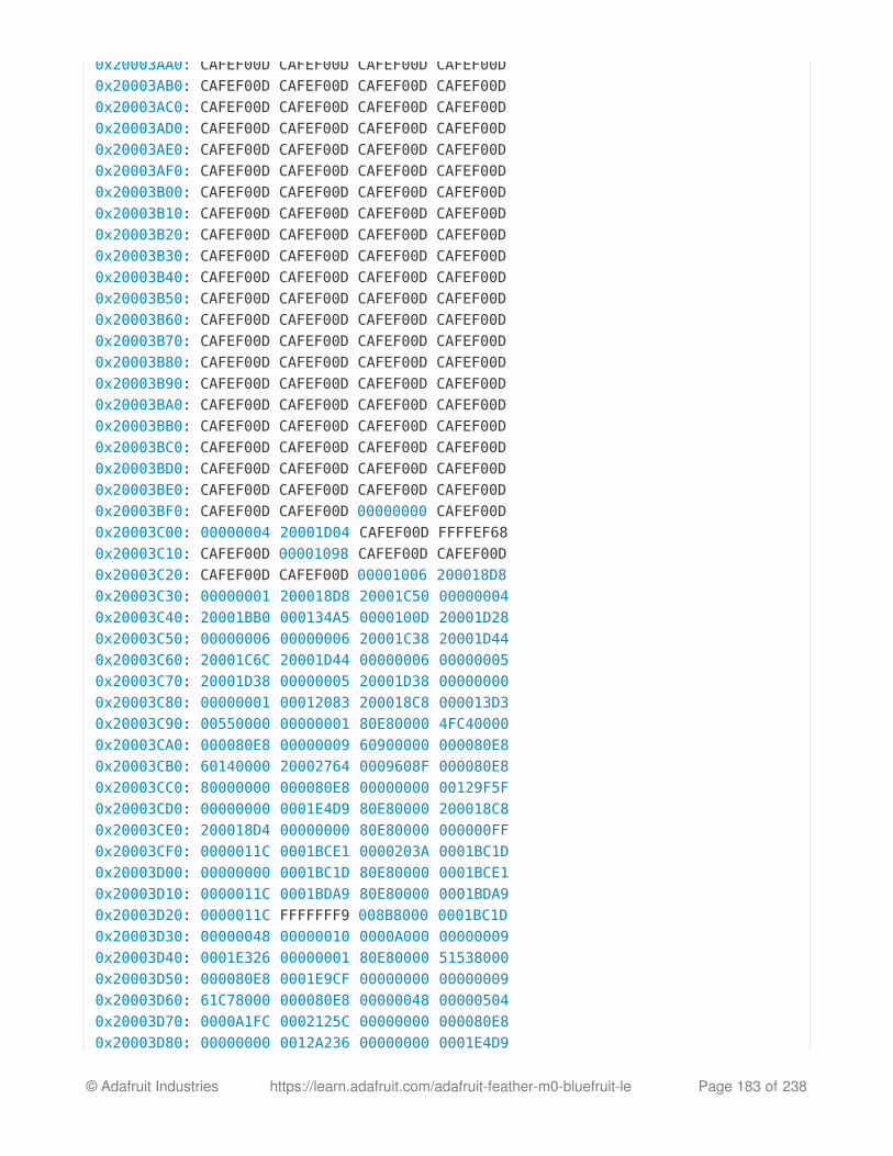
0x20003AA0: CAFEF00D CAFEF00D CAFEF00D CAFEF00D0x20003AB0: CAFEF00D CAFEF00D CAFEF00D CAFEF00D0x20003AC0: CAFEF00D CAFEF00D CAFEF00D CAFEF00D0x20003AD0: CAFEF00D CAFEF00D CAFEF00D CAFEF00D0x20003AE0: CAFEF00D CAFEF00D CAFEF00D CAFEF00D0x20003AF0: CAFEF00D CAFEF00D CAFEF00D CAFEF00D0x20003B00: CAFEF00D CAFEF00D CAFEF00D CAFEF00D0x20003B10: CAFEF00D CAFEF00D CAFEF00D CAFEF00D0x20003B20: CAFEF00D CAFEF00D CAFEF00D CAFEF00D0x20003B30: CAFEF00D CAFEF00D CAFEF00D CAFEF00D0x20003B40: CAFEF00D CAFEF00D CAFEF00D CAFEF00D0x20003B50: CAFEF00D CAFEF00D CAFEF00D CAFEF00D0x20003B60: CAFEF00D CAFEF00D CAFEF00D CAFEF00D0x20003B70: CAFEF00D CAFEF00D CAFEF00D CAFEF00D0x20003B80: CAFEF00D CAFEF00D CAFEF00D CAFEF00D0x20003B90: CAFEF00D CAFEF00D CAFEF00D CAFEF00D0x20003BA0: CAFEF00D CAFEF00D CAFEF00D CAFEF00D0x20003BB0: CAFEF00D CAFEF00D CAFEF00D CAFEF00D0x20003BC0: CAFEF00D CAFEF00D CAFEF00D CAFEF00D0x20003BD0: CAFEF00D CAFEF00D CAFEF00D CAFEF00D0x20003BE0: CAFEF00D CAFEF00D CAFEF00D CAFEF00D0x20003BF0: CAFEF00D CAFEF00D 00000000 CAFEF00D0x20003C00: 00000004 20001D04 CAFEF00D FFFFEF680x20003C10: CAFEF00D 00001098 CAFEF00D CAFEF00D0x20003C20: CAFEF00D CAFEF00D 00001006 200018D80x20003C30: 00000001 200018D8 20001C50 000000040x20003C40: 20001BB0 000134A5 0000100D 20001D280x20003C50: 00000006 00000006 20001C38 20001D440x20003C60: 20001C6C 20001D44 00000006 000000050x20003C70: 20001D38 00000005 20001D38 000000000x20003C80: 00000001 00012083 200018C8 000013D30x20003C90: 00550000 00000001 80E80000 4FC400000x20003CA0: 000080E8 00000009 60900000 000080E80x20003CB0: 60140000 20002764 0009608F 000080E80x20003CC0: 80000000 000080E8 00000000 00129F5F0x20003CD0: 00000000 0001E4D9 80E80000 200018C80x20003CE0: 200018D4 00000000 80E80000 000000FF0x20003CF0: 0000011C 0001BCE1 0000203A 0001BC1D0x20003D00: 00000000 0001BC1D 80E80000 0001BCE10x20003D10: 0000011C 0001BDA9 80E80000 0001BDA90x20003D20: 0000011C FFFFFFF9 008B8000 0001BC1D0x20003D30: 00000048 00000010 0000A000 000000090x20003D40: 0001E326 00000001 80E80000 515380000x20003D50: 000080E8 0001E9CF 00000000 000000090x20003D60: 61C78000 000080E8 00000048 000005040x20003D70: 0000A1FC 0002125C 00000000 000080E80x20003D80: 00000000 0012A236 00000000 0001E4D9
© Adafruit Industries https://learn.adafruit.com/adafruit-feather-m0-bluefruit-le Page 183 of 238

0x20003D90: 000080E8 00000009 00004998 000080E80x20003DA0: 622C8000 0012A29B 00000042 0001E4790x20003DB0: 40011000 000185EF 00006E10 000000000x20003DC0: 00000000 00000004 0000000C 000000000x20003DD0: 62780000 00018579 2000311B 0001ACDF0x20003DE0: 00000000 20003054 20002050 000000010x20003DF0: 20003DF8 0002085D 00000001 200030D40x20003E00: 00000200 0001F663 00000001 200030D40x20003E10: 00000001 2000311B 0001F631 00020A6D0x20003E20: 00000001 00000000 0000000C 200030D40x20003E30: 2000311B 00000042 200030D4 00020AD70x20003E40: 20002050 200030D4 20002050 000208330x20003E50: 20002050 20003F1B 20002050 0001FF890x20003E60: 20002050 0001FFA3 00000005 20003ED80x20003E70: 20002050 0001FF8B 00000010 000204910x20003E80: 00000001 0012A54E 00000020 000224090x20003E90: 00000000 20002050 200030D4 0001FF8B0x20003EA0: 00021263 00000005 0000000C 20003F740x20003EB0: 20003ED8 20002050 200030D4 000201870x20003EC0: 20003ED4 20003054 00000000 20003F750x20003ED0: 00000008 20003F64 00000084 FFFFFFFF0x20003EE0: FFFFFFFF 00000008 00000001 000000080x20003EF0: 20302058 2000311B 0001F631 00020A6D0x20003F00: 20002050 00000000 0000000C 200030D40x20003F10: 32002050 32303032 00323330 000258D70x20003F20: 20002050 200030D4 20002050 000208330x20003F30: 00000000 20002050 00000020 000001CE0x20003F40: 20003F40 200030D4 00000004 0001ED830x20003F50: 200030D4 20003F60 000001D6 000001D70x20003F60: 000001D8 00016559 0000000C 000000000x20003F70: 6C383025 00000058 200030D4 FFFFFFFF0x20003F80: 1FFF4000 00000028 00000028 000217F80x20003F90: 200020C7 000166C5 000166AD 00017ED90x20003FA0: FFFFFFFF 200020B8 2000306C 200030D40x20003FB0: 200020B4 000180AD 1FFF4000 200020B00x20003FC0: 200020B0 200020B0 1FFF4000 0001A63D0x20003FD0: CAFEF00D CAFEF00D 200020B4 000000020x20003FE0: FFFFFFFF FFFFFFFF 1FFF4000 000000000x20003FF0: 00000000 00000000 00000000 00016113OK
© Adafruit Industries https://learn.adafruit.com/adafruit-feather-m0-bluefruit-le Page 184 of 238

HistoryThis page tracks additions or changes to the AT command set based on the firmware versionnumber (which you can obtain via the 'ATI' command):
Version 0.7.7
The following AT commands and features were added in the 0.7.7 release:
Added AT+BLEUARTTXF (F for force) to immediately send the specified data out in anBLE UART packet (max 20 bytes), bypassing any FIFO delays and avoiding packetspotentially being transmitted in two transactions.Adjusted BLE UART service to use min connection interval as the tx interval
Added AT+DFUIRQ to enable using the DFU Pin for IRQ purposes when there is asupported event on the nRF51822Enabled the internal pullup resistor on the CS pin for Bluefruit SPI boards
Added AT+MODESWITCHEN to enable/disable +++ mode switching from the local(serial or SPI) or BLE UART side. By default local = enabled, ble = disabled, meaningcommands can only be executed via the local interface by default.Implemented a '\+' escape code to immediately send '+' chars without trigger the +++delay waiting for further similar input
Added AT+BLEHIDGAMEPADEN to separately enable HID Gamepad, since iOS/OSXhas a conflict with gamepad devices causing HID keyboard to not work properly.
The following bugs were fixed in release 0.7.7:
Fixed a factory reset issue when a long delay occurs in app_error_handler()Fixed an issue where strings were being truncated at 64 chars in UARTFixed HID keyboard support not working with iOS 9 & 10
Version 0.7.0
The following AT commands were added in the 0.7.0 release:
AT+BAUDRATEChange the HW UART baudrateAT+UARTFLOWEnable or disable HW UART flow controlAT+BLEMIDIEN=on/off/0/1Enable/disable MIDI service, requires a reset to take affectAT+BLEMIDITX
© Adafruit Industries https://learn.adafruit.com/adafruit-feather-m0-bluefruit-le Page 185 of 238

Send a MIDI eventAT+BLEMIDIRXReceive an available MIDI eventAT+GATTCHARRAWAdded this read only command to read binary (instead of ASCII) data from acharacteristic. It is non-printable but less overhead and easier for writing library inArduinoAT+NVMWRITE=offset,datatype,dataWrites data to 256 byte user NVM. Datatype must be STRING (1), BYTEARRAY (2), orINTEGER (3)AT+NVMREAD=offset,size,datatypeReads data back from 256 bytes user NVMAT+NVMREADRAW=offset,size binary dataBinary data (instead of ASCII) is returned, ending with "OK\r\n". It is non-printable butless overhead and easier to use in some situations.AT+BLEHIDGAMEPAD=x,y,buttons
X is LEFT, RIGHT: X=-1 LEFT is pressed, X=1 RIGHT is pressed, X=0 no pressedY is UP, DOWN: Y=-1 i UP, Y=1 is DOWN, Y=0 no pressedButton [0x00-0xFF] is a bit mask for 8 button 0-7
AT+GAPCONNECTABLE=on/off/1/0Allow/disallow connection to the deviceAT+EDDYSTONESERVICEENAdd/remove EddyStone service to GATT table (requires reset)AT+EDDYSTONEBROADCAST=on/off/0/1Start/stop broadcasting url using settings from NVMAT+BLEBATTEN=on/off/1/0Enable battery service. Reset required due to the service change.AT+BLEBATTVAL=percentUpdates the Battery level, percent is 0 to 100
The following commands were changed in the 0.7.0 release:
AT+GATTADDCHAR
Added a DATATYPE option to indicate the data type for the GATT characteristic'spayload. Valid option are: AUTO (0, default), STRING (1), BYTEARRAY (2),INTEGER (3)Added characteristic user description option via the DESCRIPTION flagAdded characteristic presentation format support via the PRESENTATION flag
© Adafruit Industries https://learn.adafruit.com/adafruit-feather-m0-bluefruit-le Page 186 of 238

AT+GAPINTERVALSAdded a new 'adv_lowpower_interval' parameter, default value is 417.5 ms. Currentarguments are now: min_conn, max_conn, adv_interval, adv_timeout,adv_lowpower_interval
Key bug fixes and changes in this release:
Significant BTLE UART speed and reliability improvementsAdded callback support (work in progress) for:
BLE UART RXGATT Characteristic(s) RXMIDI RXConnect/Disconnect
Increased MAX_LEN for each characteristic from 20 to 32 bytesChanged the default GAP parameters:
Advertising interval = 20msMin connection interval = 20 msMax connection interval = 40 ms
Increased the maximum number of CCCDs saved to flash from 8 to 16Eddystone config service disabled by defaultRemoved AT+EDDYSTONEENABLE to avoid confusionChanged advertising timeout for Eddystone to 'unlimited'Fixed Write-No-Response characteristic property, which wasn't being handled properlyFixed timing constraints to meet Apple design guidelinesFixed systick to ms calculationFixed all tests with google eddystone validator except for writing tx_power = 1 dB (notvalid on nrf51)Fixed a bug where writing from the central does not update the value on thecharacteristic correctlyFixed an issue with HID examples, where when paired with Central, a disconnect thenreconnect could not send HID reports anymore
Version 0.6.7
The following AT commands were added in the 0.6.7 release:
AT+BLEUARTFIFOReturns the number of free bytes available in the TX and RX FIFOs for the BluetoothUART Service.
© Adafruit Industries https://learn.adafruit.com/adafruit-feather-m0-bluefruit-le Page 187 of 238

The following commands were changed in the 0.6.7 release:
AT+BLEUARTTXIf the TX FIFO is full, the command will wait up to 200ms to see if the FIFO sizedecreases before exiting and returning an ERROR response due to the FIFO being full.AT+BLEURIBEACONThis command will go back to using the old (deprecated) UriBeacon UUID (0xFED8),and only the AT+EDDYSTONEURL command will use the newer Eddystone UUID(0xFEAA).AT+BLEKEYBOARD and AT+BLEUARTTXThese commands now accept '\?' as an escape code since 'AT+BLEKEYBOARD=?' hasanother meaning for the AT parser. To send a single question mark the followingcommand should be used: 'AT+BLEKEYBOARD=\?' or 'AT+BLEUARTTX=\?'AT+EDDYSTONEURLThis command now accepts an optional third parameter for RSSI at 0m value (default is-18dBm). Running this command with no parameters ('AT+EDDYSTONEURL\r\n') will now returnthe current URL.
Key bug fixes in this release:
The FIFO handling for the Bluetooth UART Service was improved for speed andstability, and the TX and RF FIFOs were increased to 1024 bytes each.An issue where a timer overflow was causing factory resets every 4 hours or so hasbeen resolved.Fixed a problem with the GATT server where 'value_len' was being incorrectly parsedfor integer values in characteristics where 'max_len' >4
Version 0.6.6
The following AT commands were added in the 0.6.6 release:
AT+EDDYSTONEURLUpdate the URL for the beacon and switch to beacon modeAT+EDDYSTONEENABLEEnable/disable beacon mode using the configured urlAT+EDDYSTONECONFIGENEnable advertising for the the Eddystone configuration service for the specifiednumber of seconds
© Adafruit Industries https://learn.adafruit.com/adafruit-feather-m0-bluefruit-le Page 188 of 238

AT+HWMODELEDAllows the user to override the default MODE LED behaviour with one of the followingoptions: DISABLE, MODE, HWUART, BLEUART, SPI, MANUALAT+BLECONTROLKEYAllows HID media control values to be sent to a bonded central device (volume, screenbrightness, etc.)AT+BLEHIDENEnables or disables BLE HID support in the Bluefruit LE firmware (mouse, keyboard andmedia control)AT+BLEMOUSEMOVETo move the HID mouseAT+BLEMOUSEBUTTONTo set the state of the HID mouse buttons
The following commands were changed in the 0.6.6 release:
AT+BLEKEYBOARDEN - Now an alias for AT+BLEHIDENAT+GATTADDCHAR - Added a new UUID128 field to allow custom UUIDs
Key bug fixes in this release:
Fixed issues with long beacon URLsFixed big endian issue in at+blebeacon for major & minor number
Known issues with this release:
Windows 10 seems to support a limited number of characteristics for the DIS service.We had to disable the Serial Number characteristic to enable HID support withwindows 10.
Version 0.6.5
The following AT commands were added in the 0.6.5 release:
AT+BLEGETPEERADDR
The following commands were changed in the 0.6.5 release:
Increased the UART buffer size (on the nRF51) from 128 to 256 bytes+++ now responds with the current operating modeFixed a bug with AT+GATTCHAR values sometimes not being saved to NVM
© Adafruit Industries https://learn.adafruit.com/adafruit-feather-m0-bluefruit-le Page 189 of 238

Fixed a bug with AT+GATTCHAR max_len value not being taken into account after areset (min_len was always used when repopulating the value)
Version 0.6.2
This is the first release targetting 32KB SRAM parts (QFAC). 16KB SRAM parts can't be usedwith this firmware due to memory management issues, and should use the earlier 0.5.0firmware.
The following AT commands were changed in the 0.6.2 release:
AT+BLEUARTTXBasic escape codes were added for new lines, tabs and backspaceAT+BLEKEYBOARDAlso works with OS X now, and may function with other operating systems that supportBLE HID keyboards
Version 0.5.0
The following AT commands were added in the 0.5.0 release:
AT+BLEKEYBOARDENAT+BLEKEYBOARDAT+BLEKEYBOARDCODE
The following AT commands were changed in the 0.5.0 release:
ATIThe SoftDevice, SoftDevice version and bootloader version were added as a new (7th)record. For Ex: "S110 7.1.0, 0.0" indicates version 7.1.0 of the S110 softdevice is usedwith the 0.0 bootloader (future boards will use a newer 0.1 bootloader).
Other notes concerning 0.5.0:
Starting with version 0.5.0, you can execute the AT+FACTORYRESET command at any point(and without a terminal emulator) by holding the DFU button down for 10 seconds until theblue CONNECTED LED starts flashing, then releasing it.
Version 0.4.7
The following AT commands were added in the 0.4.7 release:
© Adafruit Industries https://learn.adafruit.com/adafruit-feather-m0-bluefruit-le Page 190 of 238

+++AT+HWRANDOMAT+BLEURIBEACONAT+DBGSTACKSIZEAT+DBGSTACKDUMP
The following commands were changed in the 0.4.7 release:
ATIThe chip revision was added after the chip name. Whereas ATI would previously report'nRF51822', it will now add the specific HW revision if it can be detected (ex 'nRF51822QFAAG00')
Version 0.3.0
First public release
© Adafruit Industries https://learn.adafruit.com/adafruit-feather-m0-bluefruit-le Page 191 of 238

Command ExamplesThe following code snippets can be used when operating in Command Mode to performspecific tasks.
Heart Rate Monitor Service
The command list below will add a Heart Rate service to the BLEFriend's attribute table, withtwo characteristics:
Heart Rate MeasurementBody Sensor Location
# Perform a factory reset to make sure we get a clean startAT+FACTORYRESETOK # Add the Heart Rate service entryAT+GATTADDSERVICE=UUID=0x180D1OK
# Add the Heart Rate Measurement characteristicAT+GATTADDCHAR=UUID=0x2A37, PROPERTIES=0x10, MIN_LEN=2, MAX_LEN=3, VALUE=00-401OK
# Add the Body Sensor Location characteristicAT+GATTADDCHAR=UUID=0x2A38, PROPERTIES=0x02, MIN_LEN=1, VALUE=32OK
# Create a custom advertising packet that includes the Heart Rate service UUIDAT+GAPSETADVDATA=02-01-06-05-02-0d-18-0a-18OK
# Reset the device to start advertising with the custom payloadATZOK
# Update the value of the heart rate measurement (set it to 0x004A)AT+GATTCHAR=1,00-4AOK
© Adafruit Industries https://learn.adafruit.com/adafruit-feather-m0-bluefruit-le Page 192 of 238

Python Script
The following code performs the same function, but has been placed inside a Pythonwrapper using PySerial to show how you can script actions for the AT parser.
import ioimport sysimport serialimport randomfrom time import sleep
filename = "hrm.py"ser = Noneserio = Noneverbose = True # Set this to True to see all of the incoming serial data
def usage(): """Displays information on the command-line parameters for this script""" print "Usage: " + filename + " <serialPort>\n" print "For example:\n" print " Windows : " + filename + " COM14" print " OS X : " + filename + " /dev/tty.usbserial-DN009WNO" print " Linux : " + filename + " /dev/ttyACM0" return
def checkargs(): """Validates the command-line arguments for this script""" if len(sys.argv) < 2: print "ERROR: Missing serialPort" usage() sys.exit(-1) if len(sys.argv) > 2: print "ERROR: Too many arguments (expected 1)." usage() sys.exit(-2)
def errorhandler(err, exitonerror=True): """Display an error message and exit gracefully on "ERROR\r\n" responses""" print "ERROR: " + err.message if exitonerror: ser.close() sys.exit(-3)
© Adafruit Industries https://learn.adafruit.com/adafruit-feather-m0-bluefruit-le Page 193 of 238
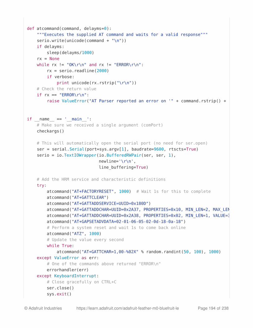
def atcommand(command, delayms=0): """Executes the supplied AT command and waits for a valid response""" serio.write(unicode(command + "\n")) if delayms: sleep(delayms/1000) rx = None while rx != "OK\r\n" and rx != "ERROR\r\n": rx = serio.readline(2000) if verbose: print unicode(rx.rstrip("\r\n")) # Check the return value if rx == "ERROR\r\n": raise ValueError("AT Parser reported an error on '" + command.rstrip() + "'"
if __name__ == '__main__': # Make sure we received a single argument (comPort) checkargs()
# This will automatically open the serial port (no need for ser.open) ser = serial.Serial(port=sys.argv[1], baudrate=9600, rtscts=True) serio = io.TextIOWrapper(io.BufferedRWPair(ser, ser, 1), newline='\r\n', line_buffering=True)
# Add the HRM service and characteristic definitions try: atcommand("AT+FACTORYRESET", 1000) # Wait 1s for this to complete atcommand("AT+GATTCLEAR") atcommand("AT+GATTADDSERVICE=UUID=0x180D") atcommand("AT+GATTADDCHAR=UUID=0x2A37, PROPERTIES=0x10, MIN_LEN=2, MAX_LEN=3, VALUE=00-40" atcommand("AT+GATTADDCHAR=UUID=0x2A38, PROPERTIES=0x02, MIN_LEN=1, VALUE=3" atcommand("AT+GAPSETADVDATA=02-01-06-05-02-0d-18-0a-18") # Perform a system reset and wait 1s to come back online atcommand("ATZ", 1000) # Update the value every second while True: atcommand("AT+GATTCHAR=1,00-%02X" % random.randint(50, 100), 1000) except ValueError as err: # One of the commands above returned "ERROR\n" errorhandler(err) except KeyboardInterrupt: # Close gracefully on CTRL+C ser.close() sys.exit()
© Adafruit Industries https://learn.adafruit.com/adafruit-feather-m0-bluefruit-le Page 194 of 238

The results of this script can be seen below in the 'HRM' app of Nordic's nRF Toolboxapplication:
Please note that nRF Toolbox will only display HRM data if the value changes, soyou will need to update the Heart Rate Measurement characteristic at least onceafter opening the HRM app and connecting to the BLEFriend
© Adafruit Industries https://learn.adafruit.com/adafruit-feather-m0-bluefruit-le Page 195 of 238

© Adafruit Industries https://learn.adafruit.com/adafruit-feather-m0-bluefruit-le Page 196 of 238

SDEP (SPI Data Transport)In order to facilitate switching between UART and SPI based Bluefruit LE modules, theBluefruit LE SPI Friend and Shield uses the same AT command set at the UART modules( ATI , AT+HELP , etc.).
These text-based AT commands are encoded as binary messages using a simple binary
protocol we've named SDEP (Simple Data Exhange Protocol).
SDEP Overview
SDEP was designed as a bus neutral protocol to handle binary commands and responses --including error responses -- in a standard, easy to extend manner. 'Bus neutral' means thatwe can use SDEP regardless of the transport mechanism (USB HID, SPI, I2C, Wireless dataover the air, etc.).
All SDEP messages have a four byte header, and in the case of the Bluefruit LE modules up
to a 16 byte payloads. Larger messages are broken up into several 4+16 bytes messagechunks which are rebuilt at either end of the transport bus. The 20 byte limit (4 byte header +16 byte payload) was chosen to take into account the maximum packet size in Bluetooth LowEnergy 4.0 (20 bytes per packet).
SPI Setup
While SDEP is bus neutral, in the case of the Bluefruit LE SPI Friend or Shield, an SPItransport is used with the following constraints and assumptions, largely to take into accountthe HW limitations of the nRF51822 system on chip:
SPI Hardware Requirements
The SPI clock should run <=4MHzA 100us delay should be added between the moment that the CS line is asserted, andbefore any data is transmitted on the SPI busThe CS line must remain asserted for the entire packet, rather than toggling CS everybyteThe CS line can however be deasserted and then reasserted between individual SDEP
Most of the time, you never need to deal with SDEP directly, but we've documentedthe protocol here in case you need understand the Bluefruit LE SPI interface indepth!
© Adafruit Industries https://learn.adafruit.com/adafruit-feather-m0-bluefruit-le Page 197 of 238

packets (of up to 20 bytes each).The SPI commands must be setup to transmit MSB (most significant bit) first (not LSBfirst)
IRQ Pin
The IRQ line is asserted by the Bluefruit LE SPI Friend/Shield as long as an entire SDEPpacket is available in the buffer on the nRF51822, at which point you should read the packet,keeping the CS line asserted for the entire transaction (as detailed above).
The IRQ line will remain asserted as long as one or more packets are available, so the linemay stay high after reading a packet, meaning that more packets are still available in theFIFO on the SPI slave side.
SDEP Packet and SPI Error Identifier
Once CS has been asserted and the mandatory 100us delay has passed, a single byteshould be read from the SPI bus which will indicate the type of payload available on thenRF51822 (see Message Type Indicator below for more information on SDEP messagetypes). Keep CS asserted after this byte has been read in case you need to continue readingthe rest of the frame.
If a standard SDEP message type indicator (0x10, 0x20, 0x40 or 0x80) is encountered, keepreading as normal. There are two other indicators that should be taken into account, though,which indicate a problem on the nRF51822 SPI slave side:
0xFE: Slave device not ready (wait a bit and try again)
0xFF: Slave device read overflow indicator (you've read more data than is available)
This means there are six possible response bytes reading the message type indicator (thefirst byte read after an SDEP command is sent): 0x10, 0x20, 0x40, 0x80, which indicate avalid message type, or 0xFE, 0xFF which indicate an error condition.
Sample Transaction
The following image shows a sample SDEP response that is spread over two packets (sincethe response is > 20 bytes in size). Notice that the IRQ line stays asserted between thepackets since more than one packet was available in the FIFO on the Bluefruit LE SPI side:
© Adafruit Industries https://learn.adafruit.com/adafruit-feather-m0-bluefruit-le Page 198 of 238

SDEP (Simple Data Exchange Protocol)
The Simple Data Exchange Protocol (SDEP) can be used to send and receive binarymessages between two connected devices using any binary serial bus (USB HID, USB Bulk,SPI, I2C, Wireless, etc.), exchanging data using one of four distinct message types(Command, Response, Alert and Error messages).
The protocol is designed to be flexible and extensible, with the only requirement being that
individual messages are 20 bytes or smaller, and that the first byte of every message is aone byte (U8) identifier that indicates the message type, which defines the format for theremainder of the payload.
Endianness
All values larger than 8-bits are encoded in little endian format. Any deviation from this ruleshould be clearly documented.
Message Type Indicator
The first byte of every message is an 8-bit identifier called the Message Type Indicator. Thisvalue indicates the type of message being sent, and allows us to determine the format forthe remainder of the message.
SDEP Data Transactions
Message Type
Command
Response
Alert
Error
ID (U8)
0x10
0x20
0x40
0x80
© Adafruit Industries https://learn.adafruit.com/adafruit-feather-m0-bluefruit-le Page 199 of 238

Either connected device can initiate SDEP transactions, though certain transport protocolsimposes restrictions on who can initiate a transfer. The master device, for example, alwaysinitiates transactions with Bluetooth Low Energy or USB, meaning that slave devices can onlyreply to incoming commands.
Every device that receives a Command Message must reply with a Response Message, ErrorMessage or Alert message.
Message Types
Command Messages
Command messages (Message Type = 0x10) have the following structure:
Command ID (bytes 1-2) and Payload Length (byte 3) are mandatory in any commandmessage. The message payload is optional, and will be ignored if Payload Length is set to 0bytes. When a message payload is present, it’s length can be anywhere from 1..16 bytes, tostay within the 20-byte maximum message length.
A long command (>16 bytes payload) must be divided into multiple packets. To facilitate this,
the More data field (bit 7 of byte 3) is used to indicate whether additional packets areavailable for the same command. The SDEP receiver must continue to reads packets until it
finds a packet with More data == 0, then assemble all sub-packets into one command ifnecessary.
The contents of the payload are user defined, and can change from one command toanother.
A sample command message would be:
Name
Message Type
Command ID
Payload Length
Payload
Type
U8
U16
U8
...
Meaning
Always '0x10'
Unique Command Identifier
[7] More data [6-5] Reserved [4-0] Payload length (0..16)
Optional command payload (parameters, etc.)
© Adafruit Industries https://learn.adafruit.com/adafruit-feather-m0-bluefruit-le Page 200 of 238

The first byte is the Message Type (0x10), which identifies this as a command message.The second and third bytes are 0x1234 (34 12 in little-endian notation), which is theunique command ID. This value will be compared against the command lookup tableand redirected to an appropriate command handler function if a matching entry wasfound.The fourth byte indicates that we have a message payload of 1 byteThe fifth byte is the 1 byte payload: 0xFF
Response Messages
Response messages (Message Type = 0x20) are generated in response to an incomingcommand, and have the following structure:
By including the Command ID that this response message is related to, the recipient canmore easily correlate responses and commands. This is useful in situations where multiplecommands are sent, and some commands may take a longer period of time to execute thansubsequent commands with a different command ID.
Response messages can only be generate in response to a command message, so the
10 34 12 01 FF
0: Message Type (U8)
1+2: Command ID (U16)
3: Payload Len (U8)
4: Payload (...)
0x10
0x34 0x12
0x01
0xFF
Name
Message Type
Command ID
Payload Length
Payload
Type
U8
U16
U8
Meaning
Always '0x20'
Command ID this message is a response to
[7] More data [6-5] Reserved [4-0] Payload length (0..16)
Optional response payload (parameters, etc.)
© Adafruit Industries https://learn.adafruit.com/adafruit-feather-m0-bluefruit-le Page 201 of 238

Command ID field should always be present.
A long response (>16 bytes payload) must be divided into multiple packets. Similar to long
commands, the More data field (bit 7 of byte 3) is used to indicate whether additional packetsare available for the same response. On responses that span more than one packet, the
More data bit on the final packet will be set to 0 to indicate that this is the last packet in thesequence. The SDEP receiver must re-assemble all sub-packets in into one payload whennecessary.
If more precise command/response correlation is required a custom protocol should bedeveloped, where a unique message identifier is included in the payload of eachcommand/response, but this is beyond the scope of this high-level protocol definition.
A sample response message would be:
The first byte is the Message Type (0x20), which identifies this as a response message.The second and third bytes are 0x1234, which is the unique command ID that thisresponse is related to.The fourth byte indicates that we have a message payload of 1 byte.The fifth byte is the 1 byte payload: 0xFF
Alert Messages
Alert messages (Message Type = 0x40) are sent whenever an alert condition is present onthe system (low battery, etc.), and have the following structure:
20 34 12 01 FF
0: Message Type (U8)
1+2: Command ID (U16)
3: Payload Len (U8)
4: Payload
0x20
0x34 0x12
0x01
0xFF
© Adafruit Industries https://learn.adafruit.com/adafruit-feather-m0-bluefruit-le Page 202 of 238

A sample alert message would be:
The first byte is the Message Type (0x40), which identifies this as an alert message.The second and third bytes are 0xABCD, which is the unique alert ID.The fourth byte indicates that we have a message payload of 4 bytes.The last four bytes are the actual payload: 0x10000742 in this case, assuming we weretransmitting a 32-bit value in little-endian format.
Standard Alert IDs
Alert IDs in the range of 0x0000 to 0x00FF are reserved for standard SDEP alerts, and maynot be used by custom alerts.
The following alerts have been defined as a standard part of the protocol:
Name
Message Type
Alert ID
Payload Length
Payload
Type
U8
U16
U8
...
Meaning
Always '0x40'
Unique ID for the Alert Condition
Payload Length (0..16)
Optional response payload
40 CD AB 04 42 07 00 10
0: Message Type (U8)
1+2: Alert ID (U16)
3: Payload Length
4+5+6+7: Payload
0x40
0xCD 0xAB
0x04
0x42 0x07 0x00 0x10
© Adafruit Industries https://learn.adafruit.com/adafruit-feather-m0-bluefruit-le Page 203 of 238

Error Messages
Error messages (Message Type = 0x80) are returned whenever an error condition is presenton the system, and have the following structure:
Whenever an error condition is present and the system needs to be alerted (such as a failedrequest, an attempt to access a non-existing resource, etc.) the system can return a specificerror message with an appropriate Error ID.
A sample error message would be:
Standard Error IDs
Error IDs in the range of 0x0000 to 0x00FF are reserved for standard SDEP errors, and maynot be used by custom errors.
The following errors have been defined as a standard part of the protocol:
ID
0x0000
0x0001
0x0002
0x0003
Alert
Reserved
System Reset
Battery Low
Battery Critical
Description
Reserved for future use
The system is about to reset
The battery level is low
The battery level is critically low
Name
Message Type
Error ID
Reserved
Type
U8
U16
U8
Meaning
Always '0x80'
Unique ID for the error condition
Reserved for future use
80 01 00 00
0: Message ID (U8)
1+2: Error ID (U16)
3: Reserved (U8)
0x80
0x01 0x00
0x00
© Adafruit Industries https://learn.adafruit.com/adafruit-feather-m0-bluefruit-le Page 204 of 238

Existing Commands
At present, there are only four SDEP commands implemented in the Bluefruit SPIFRIEND32firmware:
SDEP_CMDTYPE_INITIALIZE = 0xBEEFSDEP_CMDTYPE_AT_WRAPPER = 0x0A00SDEP_CMDTYPE_BLE_UARTTX = 0x0A01SDEP_CMDTYPE_BLE_UARTRX = 0x0A02
SDEP_CMDTYPE_INITIALIZE can be used to reset the SDEP system when a HW RST lineisn't available.
The two SDEP_CMDTYPE_UART* commands send data over the BLE UART service.
SDEP_CMDTYPE_AT_WRAPPER is the command you will use most of the time, which is awrapper that sends AT commands over the binary SDEP transport. This isn't terribly efficient,and a binary mechanism would have taken less bytes per command, but it allows the reuseof all of the earlier AT parser commands without having to implement one wrapper for everycommand which would significantly increase the overall code size.
SDEP AT Wrapper Usage
To use the SDEP AT Wrapp you simply send the correct header, along with the AT commandyou which to send to the parser. For example:
Message Type: 0x10 (Command)Command ID: 0x0A00Command Payload Length: 3 bytesCommand Payload: 'a' + 't' + 'i'
ID
0x0000
0x0001
0x0003
Error
Reserved
Invalid CMD ID
Invalid Payload
Description
Reserved for future use
CMD ID wasn't found in the lookup table
The message payload was invalid
10-00-0A-03-‘a’-‘t’-‘I’
© Adafruit Industries https://learn.adafruit.com/adafruit-feather-m0-bluefruit-le Page 205 of 238

This will cause the ATI command to be executed, which will return basic system information.
© Adafruit Industries https://learn.adafruit.com/adafruit-feather-m0-bluefruit-le Page 206 of 238

GATT Service DetailsData in Bluetooth Low Energy is organized around units called 'GATT Services' and 'GATTCharacteristics'. To expose data to another device, you must instantiate at least one serviceon your device.
Adafruit's Bluefruit LE Pro modules support some 'standard' services, described below (moremay be added in the future).
UART Service
The UART Service is the standard means of sending and receiving data between connecteddevices, and simulates a familiar two-line UART interface (one line to transmit data, anotherto receive it).
The service is described in detail on the dedicated UART Service page.
© Adafruit Industries https://learn.adafruit.com/adafruit-feather-m0-bluefruit-le Page 207 of 238

UART ServiceBase UUID: 6E400001-B5A3-F393- E0A9- E50E24DCCA9E
This service simulates a basic UART connection over two lines, TXD and RXD.
It is based on a proprietary UART service specification by Nordic Semiconductors. Data sentto and from this service can be viewed using the nRFUART apps from NordicSemiconductors for Android and iOS.
Characteristics
Nordic’s UART Service includes the following characteristics:
R = Read; W = Write; N = Notify; I = Indicate
TX (0x0002)
This characteristic is used to send data back to the sensor node, and can be written to by theconnected Central device (the mobile phone, tablet, etc.).
RX (0x0003)
This characteristic is used to send data out to the connected Central device. Notify can beenabled by the connected device so that an alert is raised every time the TX channel isupdated.
This service is available on every Bluefruit LE module and is automatically startedduring the power-up sequence.
Name
TX
RX
MandatoryYesYes
UUID0x00020x0003
TypeU8[20]U8[20]
R
X
WX
N
X
I
Characteristic names are assigned from the point of view of the Central device
© Adafruit Industries https://learn.adafruit.com/adafruit-feather-m0-bluefruit-le Page 208 of 238

Software ResourcesTo help you get your Bluefruit LE module talking to other Central devices, we've put togethera number of open source tools for most of the major platforms supporting Bluetooth LowEnergy.
Bluefruit LE Client Apps and Libraries
Adafruit has put together the following mobile or desktop apps and libraries to make it aseasy as possible to get your Bluefruit LE module talking to your mobile device or laptop, withfull source available where possible:
Bluefruit LE Connect (Android/Java)
Bluetooth Low Energy support was added to Android starting with Android 4.3 (though it wasonly really stable starting with 4.4), and we've already released Bluefruit LE Connect to thePlay Store.
The full source code for Bluefruit LE Connect for Android is also available on Github to helpyou get started with your own Android apps. You'll need a recent version of AndroidStudio to use this project.
Bluefruit LE Connect (iOS/Swift)
Apple was very early to adopt Bluetooth Low Energy, and we also have an iOS version of theBluefruit LE Connect app available in Apple's app store.
The full swift source code for Bluefruit LE Connect for iOS is also available on Github. You'llneed XCode and access to Apple's developper program to use this project:
Version 1.x source code: https://github.com/adafruit/Bluefruit_LE_Connect
© Adafruit Industries https://learn.adafruit.com/adafruit-feather-m0-bluefruit-le Page 209 of 238

Version 2.x source code: https://github.com/adafruit/Bluefruit_LE_Connect_v2
Bluefruit LE Connect for OS X (Swift)
This OS X desktop application is based on the same V2.x codebase as the iOS app, andgives you access to BLE UART, basic Pin I/O and OTA DFU firmware updates from theconvenience of your laptop or mac.
This is a great choice for logging sensor data locally and exporting it as a CSV, JSON or XMLfile for parsing in another application, and uses the native hardware on your computer so noBLE dongle is required on any recent mac.
The full source is also available on Github.
Version 2.x of the app is a complete rewrite that includes iOS, OS X GUI and OS Xcommand-line tools in a single codebase.
© Adafruit Industries https://learn.adafruit.com/adafruit-feather-m0-bluefruit-le Page 210 of 238

Bluefruit LE Command Line Updater for OS X (Swift)
This experimental command line tool is unsupported and provided purely as a proof ofconcept, but can be used to allow firmware updates for Bluefruit devices from the commandline.
This utility performs automatic firmware updates similar to the way that the GUI applicationdoes, by checking the firmware version on your Bluefruit device (via the Device InformationService), and comparing this against the firmware versions available online, downloadingfiles in the background if appropriate.
Simply install the pre-compiled tool via the DMG file and place it somewhere in the systempath, or run the file locally via './bluefruit' to see the help menu:
© Adafruit Industries https://learn.adafruit.com/adafruit-feather-m0-bluefruit-le Page 211 of 238

Deprecated: Bluefruit Buddy (OS X)
This native OS X application is a basic proof of concept app that allows you to connect toyour Bluefruit LE module using most recent macbooks or iMacs. You can get basicinformation about the modules and use the UART service to send and receive data.
The full source for the application is available in the github repo atAdafruit_BluefruitLE_OSX.
$ ./bluefruitbluefruit v0.3Usage: bluefruit <command> [options...]
Commands: Scan peripherals: scan Automatic update: update [--enable-beta] [--uuid <uuid>] Custom firmware: dfu --hex <filename> [--init <filename>] [--uuid <uuid>] Show this screen: --help Show version: --version
Options: --uuid <uuid> If present the peripheral with that uuid is used. If not present a list of peripherals --enable-beta If not present only stable versions are used
Short syntax: -u = --uuid, -b = --enable-beta, -h = --hex, -i = --init, -v = --version, -? = --
© Adafruit Industries https://learn.adafruit.com/adafruit-feather-m0-bluefruit-le Page 212 of 238

ABLE (Cross Platform/Node+Electron)
ABLE (Adafruit Bluefruit LE Desktop) is a cross-platform desktop application based onSandeep Misty's noble library and the Electron project from Github (used by Atom).
It runs on OS X, Windows 7+ and select flavours of Linux (Ubuntu tested locally). Windows 7support is particularly interesting since Windows 7 has no native support for Bluetooth LowEnergy but the noble library talks directly to supported Bluetooth 4.0 USB dongles toemulate BLE on the system (though at this stage it's still in early BETA and drops theconnection and takes more care to work with).
This app allows you to collect sensor data or perform many of the same functionality offeredby the mobile Bluefruit LE Connect apps, but on the desktop.
The app is still in BETA, but full source is available in addition to the easy to use pre-compiled binaries.
© Adafruit Industries https://learn.adafruit.com/adafruit-feather-m0-bluefruit-le Page 213 of 238

Bluefruit LE Python Wrapper
As a proof of concept, we've played around a bit with getting Python working with the nativeBluetooth APIs on OS X and the latest version of Bluez on certain Linux targets.
There are currently example sketches showing how to retreive BLE UART data as well assome basic details from the Device Information Service (DIS).
This isn't an actively support project and was more of an experiment, but if you have a recentMacbook or a Raspberry Pi and know Python, you might want to look atAdafruit_Python_BluefruitLE in our github account.
Debug Tools
If your sense of adventure gets the better of you, and your Bluefruit LE module goes off intothe weeds, the following tools might be useful to get it back from unknown lands.
© Adafruit Industries https://learn.adafruit.com/adafruit-feather-m0-bluefruit-le Page 214 of 238

AdaLink (Python)
This command line tool is a python-based wrapper for programming ARM MCUs using eithera Segger J-Link or an STLink/V2. You can use it to reflash your Bluefruit LE module using thelatest firmware from the Bluefruit LE firmware repo.
Details on how to use the tool are available in the readme.md file on the mainAdafruit_Adalink repo on Github.
Completely reprogramming a Bluefruit LE module with AdaLink would require four files, andwould look something like this (using a JLink):
You can also use the AdaLink tool to get some basic information about your module, such aswhich SoftDevice is currently programmed or the IC revision (16KB SRAM or 32KB SRAM) viathe --info command:
Adafruit nRF51822 Flasher (Python)
Adafruit's nRF51822 Flasher is an internal Python tool we use in production to flash boardsas they go through the test procedures and off the assembly line, or just testing against
These debug tools are provided purely as a convenience for advanced users fordevice recovery purposes, and are not recommended unless you're OK withpotentially bricking your board. Use them at your own risk.
adalink nrf51822 --programmer jlink --wipe --program-hex "Adafruit_BluefruitLE_Firmware/softdevice/s110_nrf51_8.0.0_softdevice.hex" --program-hex "Adafruit_BluefruitLE_Firmware/bootloader/bootloader_0002.hex" --program-hex "Adafruit_BluefruitLE_Firmware/0.6.7/blefriend32/blefriend32_s110_xxac_0_6_7_150917_blefriend32.hex" --program-hex "Adafruit_BluefruitLE_Firmware/0.6.7/blefriend32/blefriend32_s110_xxac_0_6_7_150917_blefriend32_signature.hex"
$ adalink nrf51822 -p jlink --infoHardware ID : QFACA10 (32KB)Segger ID : nRF51822_xxACSD Version : S110 8.0.0Device Addr : **:**:**:**:**:**Device ID : ****************
© Adafruit Industries https://learn.adafruit.com/adafruit-feather-m0-bluefruit-le Page 215 of 238

different firmware releases when debugging.
It relies on AdaLink or OpenOCD beneath the surface (see above), but you can use thiscommand line tool to flash your nRF51822 with a specific SoftDevice, Bootloader andBluefruit firmware combination.
It currently supports using either a Segger J-Link or STLink/V2 via AdaLink, or GPIO on aRaspberry Pi if you don't have access to a traditional ARM SWD debugger. (A pre-builtversion of OpenOCD for the RPi is included in the repo since building it from scratch takes along time on the original RPi.)
We don't provide active support for this tool since it's purely an internal project, but made itpublic just in case it might help an adventurous customer debrick a board on their own.
$ python flash.py --jtag=jlink --board=blefriend32 --softdevice=8.0.0 --bootloaderjtag : jlinksoftdevice : 8.0.0bootloader : 2board : blefriend32firmware : 0.6.7Writing Softdevice + DFU bootloader + Application to flash memoryadalink -v nrf51822 --programmer jlink --wipe --program-hex "Adafruit_BluefruitLE_Firmware/softdevice/s110_nrf51_8.0.0_softdevice.hex"...
© Adafruit Industries https://learn.adafruit.com/adafruit-feather-m0-bluefruit-le Page 216 of 238

BLE FAQ
Can I talk to Classic Bluetooth devices with a Bluefruit LE modules?
No. Bluetooth Low Energy and 'Classic' Bluetooth are both part of the same BluetoothCore Specification -- defined and maintained by the Bluetooth SIG -- but they arecompletely different protocols operating with different physical constraints andrequirements. The two protocols can't talk to each other directly.
Can my Bluefruit LE module connect to other Bluefruit LE peripherals
No, the Bluefruit LE firmware from Adafruit is currently peripheral only, and doesn't run inCentral mode, which would cause the module to behave similar to your mobile phone orBLE enabled laptop.
If you required Central support, you should look at the newer nRF52832 based productslike the Adafruit Feather nRF52 Bluefruit LE, which contains a SoftDevice which is capableof running in either Central or Peripheral mode. The nRF518322 based products (such as
the one used in this learning guide) are not capable of running in Central mode because itisn't supported by the SoftDevice they use, and it isn't possible to update the SoftDevicesafely without special hardware.
Why are none of my changes persisting when I reset with the sample sketches?
In order to ensure that the Bluefruit LE modules are in a known state for the Adafruit demosketches, most of them perform a factory reset at the start of the sketch.
This is useful to ensure that the sketch functions properly, but has the side effect oferasing any custom user data in NVM and setting everything back to factory defaultsevery time your board comes out of reset and the sketch runs.
To disable factory reset, open the demo sketch and find the FACTORYRESET_ENABLEflag and set this to '0', which will prevent the factory reset from happening at startup.
If you don't see the 'FACTORYRESET_ENABLE' flag in your .ino sketch file, you probablyhave an older version of the sketches and may need to update to the latest version via theArduino library manager.
Do I need CTS and RTS on my UART based Bluefruit LE Module?
Using CTS and RTS isn't strictly necessary when using HW serial, but they should both beused with SW serial, or any time that a lot of data is being transmitted.
© Adafruit Industries https://learn.adafruit.com/adafruit-feather-m0-bluefruit-le Page 217 of 238

The reason behind the need for CTS and RTS is that the UART block on the nRF51822isn't very robust, and early versions of the chip had an extremely small FIFO meaning thatthe UART peripheral was quickly overwhelmed.
Using CTS and RTS significantly improves the reliability of the UART connection sincethese two pins tell the device on the other end when they need to wait while the existingbuffered data is processed.
To enable CTS and RTS support, go into the BluefruitConfig.h file in your sketch folderand simply assign an appropriate pin to the macros dedicated to those functions (they maybe set to -1 if they aren't currently being used).
Enabling both of these pins should solve any data reliability issues you are having withlarge commands, or when transmitting a number of commands in a row.
How can I update to the latest Bluefruit LE Firmware?
The easiest way to keep your Bluefruit LE modules up to date is with our Bluefruit LEConnect app for Android or Bluefruit LE Connect for iOS. Both of these apps include afirmware update feature that allows you to automatically download the latest firmware andflash your Bluefruit LE device in as safe and painless a manner as possible. You can alsoroll back to older versions of the Bluefruit LE firmware using these apps if you need to dosome testing on a previous version.
Which firmware version supports 'xxx'?
We regularly release Bluefruit LE firmware images with bug fixes and new features. EachAT command in this learning guide lists the minimum firmware version required to usethat command, but for a higher level overview of the changes from one firmware versionto the next, consult the firmware history page.
Does my Bluefruit LE device support ANCS?
ANCS is on the roadmap for us (most likely in the 0.7.x release family), but we don'tcurrently support it since there are some unusual edge cases when implementing it as aservice.
My Bluefruit LE device is stuck in DFU mode ... what can I do?
If your device is stuck in DFU mode for some reason and the firmware was corrupted, youhave several options.
© Adafruit Industries https://learn.adafruit.com/adafruit-feather-m0-bluefruit-le Page 218 of 238

First, try a factory reset by holding down the DFU button for about 10 seconds until theCONN LED starts flashing, then release the DFU button to perform a factory reset.
If this doesn't work, you may need to reflash your firmware starting from DFU mode, whichcan be done in one of the following ways:
Bluefruit LE Connect (Android)
Place the module in DFU mode (constant LED blinky)Open Bluefruit LE ConnectConnect to the 'DfuTarg' deviceOnce connected, you will see a screen with some basic device information. Click
the '...' in the top-right corner and select Firmware Updates
Click the Use Custom Firmware buttonSelect the appropriate .hex and .init files (copied from the Bluefruit LE Firmwarerepo) ... for the BLEFRIEND32 firmware version 0.6.7, this would be:
Hex File: blefriend32_s110_xxac_0_6_7_150917_blefriend32.hexInit File: blefriend32_s110_xxac_0_6_7_150917_blefriend32_init.dat
Click Start Update
Unfortunately, the iOS app doesn't yet support custom firmware updates from DFU modeyet, but we will get this into the next release.
Nordic nRF Toolbox
You can also use Nordic's nRF Toolbox application to update the firmware using the OTAbootloader.
On Android:
Open nRF Toolbox (using the latest version)
Click the DFU icon
Click the Select File button
Select Application from the radio button list, then click OKFind the appropriate .hex file(ex. 'blefriend32_s110_xxac_0_6_7_150917_blefriend32.hex')
When asked about the 'Init packet', indicate Yes, and select the appropriate*_init.dat file (for example:'blefriend32_s110_xxac_0_6_7_150917_blefriend32_init.dat').
Click the Select Device button at the bottom of the main screen and find
the DfuTarg device, clicking on it
© Adafruit Industries https://learn.adafruit.com/adafruit-feather-m0-bluefruit-le Page 219 of 238

Click the Upload button, which should now be enabled on the home screenThis will begin the DFU update process which should cause the firmware to beupdated or restored on your Bluefruit LE module
On iOS:
Create a .zip file containing the .hex file and init.dat file that you will use for thefirmware update. For example:
Rename
'blefriend32_s110_xxac_0_6_7_150917_blefriend32.hex' to application.hexRename 'blefriend32_s110_xxac_0_6_7_150917_blefriend32_init.dat'
to application.dat
Upload the .zip file containing the application.hex and application.dat files to youriPhone using uTunes, as described hereOpen the nRF Toolbox app (using the latest version)
Click the DFU icon
Click the Select File text label
Switch to User Files to see the .zip file you uploaded aboveSelect the .zip file (ex. blefriend32_065.zip)
On the main screen select Select File Type
Select application
On the main screen select SELECT DEVICE
Select DfuTarg
Click the Upload button which should now be enabledThis will begin the DFU process and your Bluefruit LE module will reset when theupdate is completeIf you get the normal 2 or 3 pulse blinky pattern, the update worked!
Adafruit_nRF51822_Flasher
As a last resort, if you have access to a Raspberry Pi, a Segger J-Link or a STLink/V2, youcan also try manually reflashing the entire device, as described in the FAQ above, withfurther details on the Software Resources page.
How do I reflash my Bluefruit LE module over SWD?
Reflashing Bluefruit LE modules over SWD (ex. switching to the sniffer firmware and back)
is at your own risk and can lead to a bricked device, and we can't offer any support for
this operation! You're on your own here, and there are unfortunately 1,000,000 thingsthat can go wrong, which is why we offer two separate Bluefruit LE Friend boards -- thesniffer and the normal Bluefruit LE Friend board with the non-sniffer firmware, which
© Adafruit Industries https://learn.adafruit.com/adafruit-feather-m0-bluefruit-le Page 220 of 238

provides a bootloader with fail safe features that prevents you from ever bricking boardsvia OTA updates.
AdaLink (SWD/JTAG Debugger Wrapper)
Transitioning between the two board types (sniffer and Bluefruit LE module) isunfortunately not a risk-free operation, and requires external hardware, software andknow-how to get right, which is why it isn't covered by our support team.
That said ... if you're determined to go down that lonely road, and you have a Segger J-Link (which is what we use internally for production and development), or have alreadyerased your Bluefruit LE device, you should have a look at AdaLink, which is the tool weuse internally to flash the four files required to restore a Bluefruit LE module. (Note: recentversion of AdaLink also support the cheaper STLink/V2, though the J-Link is generallymore robust if you are going to purchase a debugger for long term use.)
The mandatory Intel Hex files are available in the Bluefruit LE Firmware repo. You willneed to flash:
An appropriate bootloader imageAn appropriate SoftDevice imageThe Bluefruit LE firmware imageThe matching signature file containing a CRC check so that the bootloader acceptsthe firmware image above (located in the same folder as the firmware image)
The appropriate files are generally listed in the version control .xml file in the firmwarerepository.
If you are trying to flash the sniffer firmware (at your own risk!), you only need to flash asingle .hex file, which you can find here. The sniffer doesn't require a SoftDevice image,and doesn't use the fail-safe bootloader -- which is why changing is a one way and riskyoperation if you don't have a supported SWD debugger.
Adafruit_nF51822_Flasher
We also have an internal python tool available that sits one level higher than AdaLink(referenced above), and makes it easier to flash specific versions of the official firmware toa Bluefruit LE module. For details, see the Adafruit_nRF51822_Flasher repo.
Can I access BETA firmware releases?
The latest versions of the Bluefruit LE Connect applications for iOS and Android allow you
© Adafruit Industries https://learn.adafruit.com/adafruit-feather-m0-bluefruit-le Page 221 of 238

to optionally update your Bluefruit LE modules with pre-release or BETA firmware.
This functionality is primarilly provided as a debug and testing mechanism for supportissues in the forum, and should only be used when trying to identify and resolve specificissues with your modules!
Enabling BETA Releases on iOS
Make sure you have at least version 1.7.1 of Bluefruit LE ConnectGo to the Settings page
Scroll to the bottom of the Settings page until you find Bluefruit LE
Click on the Bluefruit LE icon and enable the Show beta releases switchYou should be able to see any BETA releases available in the firmware repo nowwhen you use Bluefruit LE Connect
Enabling BETA Releases on Android
Make sure you have the latest version of Bluefruit LE ConnectOpen the Bluefruit LE Connect applicationClick the "..." icon in the top-right corner of the app's home screen
Select Settings
Scroll down to the Software Updates section and enable Show beta releasesYou should be able to see any BETA releases available in the firmware repo nowwhen you use Bluefruit LE Connect
Why can't I see my Bluefruit LE device after upgrading to Android 6.0?
In Android 6.0 there were some important security changes that affect Bluetooth LowEnergy devices. If location services are unavailable (meaning the GPS is turned off) youwon't be able to see Bluetooth Low Energy devices advertising either. See this issue fordetails.
Be sure to enable location services on your Android 6.0 device when using Bluefruit LEConnect or other Bluetooth Low Energy applications with your Bluefruit LE modules.
What is the theoretical speed limit for BLE?
This depends on a variety of factors, and is determined by the capabilities of the centraldevice (the mobile phone, etc.) as much as the peripheral.
Taking the HW limits on the nR51822 into account (max 6 packets per connection interval,and a minimum connection interval of 7.5ms) you end up with the following theoreticallimits on various mobile operating systems:
© Adafruit Industries https://learn.adafruit.com/adafruit-feather-m0-bluefruit-le Page 222 of 238

iPhone 5/6 + IOS 8.0/8.16 packets * 20 bytes * 1/0.030 s = 4 kB/s = 32 kbps
iPhone 5/6 + IOS 8.2/8.33 packets * 20 bytes * 1/0.030 s = 2 kB/s = 16 kbps
iPhone 5/6 + IOS 8.x with nRF80011 packet * 20 bytes * 1/0.030 s = 0.67 kB/s = 5.3 kbps
Nexus 44 packets * 20 bytes * 1/0.0075 s = 10.6 kB/s = 84 kbps
Nordic Master Emulator Firmware (MEFW) with nRF51822 0.9.01 packet * 20 bytes * 1/0.0075 = 2.67 kB/s = 21.33 kbps
Nordic Master Emulator Firmware (MEFW) with nRF51822 0.11.06 packets * 20 bytes * 1/0.0075 = 16 kB/s = 128 kbps
There are also some limits imposed by the Bluefruit LE firmware, but we are activelyworking to significantly improve the throughput in the upcoming 0.7.0 release, which willbe available Q2 2016. The above figures are useful as a theoretical maximum to decide ifBLE is appropriate for you project or not.
UPDATE: For more specific details on the limitations of various Android versions andphones, see this helpful post from Nordic Semiconductors.
Can my Bluefruit board detect other Bluefruit boards or Central devices?
No. All of our Bluefruit LE modules currently operate in peripheral mode, which meansthey can only advertise their own existence via the advertising payload. The centraldevice (usually your phone or laptop) is responsible for listening for these advertisingpackets, starting the connection process, and inititating any transactions between thedevices. There is no way for a Bluefruit module to detect other Bluefruit modules orcentral devices in range, they can only send their own advertising data out and wait for aconnection request to come in.
How can I determine the distance between my Bluefruit module and my phone in m/ft?
The short answer is: you can't.
RF devices normally measure signal strength using RSSI, which stands for Received SignalStrength Indicator, which is measured in dBm. The closer the devices are the strong theRSSI value generally is (-90dBm is much weaker than -60dBm, for example), but there isno reliable relationship between RSSI values in dBm and distance in the real world. Ifthere is a wall between devices, RSSI will fall. If there is a lot of interference on the same2.4GHz band, RSSI will fall. Depending on the device, if you simply change the antenna
© Adafruit Industries https://learn.adafruit.com/adafruit-feather-m0-bluefruit-le Page 223 of 238

orientation, RSSI will fall. You can read the RSSI value between two connected deviceswith the AT+BLEGETRSSI command, but there are no meaningful and repeatableconclusions that can be drawn from this value about distance other than perhaps 'farther'or 'closer' in a very loose sense of the terms.
How far away from my phone can I have my Bluefruit LE module?
This depends on a number of factors beyond the module itself such as antennaorientation, the antenna design on the phone, transmit power on the sending node,competing traffic in the same 2.4GHz bandwidth, obstacles between end points, etc.
It could be as low as a couple meters up to about 10 meters line of sight, but generallyBluetooth Low Energy is designed for very short range and will work best in the 5-6 meteror less range for reliable communication, assuming normal Bluefruit firmware settings.
How many GATT services and characteristics can I create?
For firmware 0.7.0 and higher, the following limitations are present:
Maximum number of services: 10Maximum number of characteristics: 30Maximum buffer size for each characteristic: 32 bytesMaximum number of CCCDs: 16
Is it possible to modify or disable the built in GATT services and characteristics (DIS, DFU,etc.)?
No, unfortunately you can't. We rely on the Device Information Service (DIS) contents toknow which firmware and bootloader version you are running, and wouldn't be able toprovide firmware updates without being able to trust this information, which i why it's bothmandatory and read only.
Similarly, the DFU service is mandatory to maintain over the air updates and disabling itwould create more problems that it's presence would cause.
How can I use BlueZ and gatttool with Bluefruit modules?
BlueZ has a bit of a learning curve associated with it, but you can find some notes belowon one option to send and receive data using the BLE UART Service built into all of ourBluefruit LE modules and boards.
These commands may change with different versions of BlueZ. Version 5.21 was usedbelow.
© Adafruit Industries https://learn.adafruit.com/adafruit-feather-m0-bluefruit-le Page 224 of 238
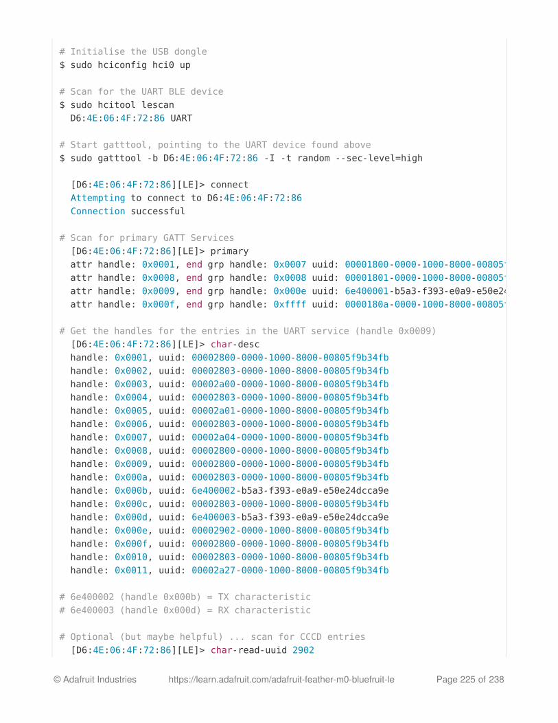
# Initialise the USB dongle$ sudo hciconfig hci0 up
# Scan for the UART BLE device$ sudo hcitool lescan D6:4E:06:4F:72:86 UART
# Start gatttool, pointing to the UART device found above$ sudo gatttool -b D6:4E:06:4F:72:86 -I -t random --sec-level=high
[D6:4E:06:4F:72:86][LE]> connect Attempting to connect to D6:4E:06:4F:72:86 Connection successful # Scan for primary GATT Services [D6:4E:06:4F:72:86][LE]> primary attr handle: 0x0001, end grp handle: 0x0007 uuid: 00001800-0000-1000-8000-00805f9b34fb attr handle: 0x0008, end grp handle: 0x0008 uuid: 00001801-0000-1000-8000-00805f9b34fb attr handle: 0x0009, end grp handle: 0x000e uuid: 6e400001-b5a3-f393-e0a9-e50e24dcca9e attr handle: 0x000f, end grp handle: 0xffff uuid: 0000180a-0000-1000-8000-00805f9b34fb
# Get the handles for the entries in the UART service (handle 0x0009) [D6:4E:06:4F:72:86][LE]> char-desc handle: 0x0001, uuid: 00002800-0000-1000-8000-00805f9b34fb handle: 0x0002, uuid: 00002803-0000-1000-8000-00805f9b34fb handle: 0x0003, uuid: 00002a00-0000-1000-8000-00805f9b34fb handle: 0x0004, uuid: 00002803-0000-1000-8000-00805f9b34fb handle: 0x0005, uuid: 00002a01-0000-1000-8000-00805f9b34fb handle: 0x0006, uuid: 00002803-0000-1000-8000-00805f9b34fb handle: 0x0007, uuid: 00002a04-0000-1000-8000-00805f9b34fb handle: 0x0008, uuid: 00002800-0000-1000-8000-00805f9b34fb handle: 0x0009, uuid: 00002800-0000-1000-8000-00805f9b34fb handle: 0x000a, uuid: 00002803-0000-1000-8000-00805f9b34fb handle: 0x000b, uuid: 6e400002-b5a3-f393-e0a9-e50e24dcca9e handle: 0x000c, uuid: 00002803-0000-1000-8000-00805f9b34fb handle: 0x000d, uuid: 6e400003-b5a3-f393-e0a9-e50e24dcca9e handle: 0x000e, uuid: 00002902-0000-1000-8000-00805f9b34fb handle: 0x000f, uuid: 00002800-0000-1000-8000-00805f9b34fb handle: 0x0010, uuid: 00002803-0000-1000-8000-00805f9b34fb handle: 0x0011, uuid: 00002a27-0000-1000-8000-00805f9b34fb
# 6e400002 (handle 0x000b) = TX characteristic# 6e400003 (handle 0x000d) = RX characteristic
# Optional (but maybe helpful) ... scan for CCCD entries [D6:4E:06:4F:72:86][LE]> char-read-uuid 2902
© Adafruit Industries https://learn.adafruit.com/adafruit-feather-m0-bluefruit-le Page 225 of 238

Can I use the IRQ pin to wake my MCU up from sleep when BLE UART data is available?
handle: 0x000e value: 00 00 # Enable notifications on the RX characteristic (CCCD handle = 0x000e)# 0100 = get notifications# 0200 = get indications# 0300 = get notifications + indications# 0000 = disable notifications + indications [D6:4E:06:4F:72:86][LE]> char-write-req 0x000e 0100 Characteristic value was written successfully
# Just to make sure it was updated [D6:4E:06:4F:72:86][LE]> char-read-hnd 0x000e Characteristic value/descriptor: 01 00 # Writing "test" in the Serial Monitor of the Arduino sketch should# cause this output not that notifications are enabled: Notification handle = 0x000d value: 74 65 73 74
# Write something to the TX characteristic (handle = 0x000b)# This should cause E F G H to appear in the Serial Monitor [D6:4E:06:4F:72:86][LE]> char-write-cmd 0x000b 45 [D6:4E:06:4F:72:86][LE]> char-write-cmd 0x000b 46 [D6:4E:06:4F:72:86][LE]> char-write-cmd 0x000b 47 [D6:4E:06:4F:72:86][LE]> char-write-cmd 0x000b 48
# To send multiple bytes [D6:4E:06:4F:72:86][LE]> char-write-cmd 0x000B 707172737475 # If you are running the callbackEcho sketch and notifications# are enabled you should get this response after the above cmd: Notification handle = 0x000d value: 70 71 72 73 74 75
--------------
# If you just want to enable constant listening, enter the following command from the CLI:$ sudo gatttool -b D6:4E:06:4F:72:86 -t random --char-write-req -a 0x000e -n 0100
# This should give us the following output as data is written on the Uno,# though we can't send anything back: Characteristic value was written successfully Notification handle = 0x000d value: 74 65 73 74 Notification handle = 0x000d value: 6d 6f 72 65 20 74 65 73 74
© Adafruit Industries https://learn.adafruit.com/adafruit-feather-m0-bluefruit-le Page 226 of 238

No, on SPI-based boards the IRQ pin is used to indicate that an SDEP response isavailable to an SDEP command. For example, when you sent the `AT+BLEUARTRX`command as an SDEP message, the Bluefruit firmware running on the nRF51822 will parsethe message, prepare an SDEP response, and trigger the IRQ pin to tell the MCU that theresponse is ready. This is completely independant from the BLE UART service, whichdoesn't have interrupt capability at present.
© Adafruit Industries https://learn.adafruit.com/adafruit-feather-m0-bluefruit-le Page 227 of 238

DFU Bluefruit UpdatesFor videos on the latest update procedure using Bluefruit LE Connect see:
iOS: https://learn.adafruit.com/introducing-adafruit-ble-bluetooth-low-energy-friend/dfu-on-iosAndroid: https://learn.adafruit.com/introducing-adafruit-ble-bluetooth-low-energy-friend/dfu-on-android-4-dot-3-plus
You can reprogram the Bluefruit LE module itself over-the-air using an Android or iOSphone/tablet. This doesn't reprogram the ATmega32u4 in the Bluefruit Micro, only the BLEmodule itself. Since its not a common thing to do, its a little challenging to do.
You will need to disconnect/unpower the Bluefruit Micro, connect a wire temporarily
between the DFU pin and GND and then power up the board via USB or battery.
The red LED will blink continuously, letting you know it's in DFU mode. Then follow our guidefor field updating the firmware
The video below is out of date and applies to early versions of the board beforethe Bluefruit LE Connect apps were available for iOS, Android and OS X in therespective app stores. To keep your device up to date, simply install and open theBluefruit LE Connect app and connect to your Bluefruit device. If a firmware updateis available, it will be automatically proposed, and the entire update process will behandled transparently for you.
© Adafruit Industries https://learn.adafruit.com/adafruit-feather-m0-bluefruit-le Page 228 of 238

Downloads
MDBT DatasheetPCB Eagle CAD Files on GitHubFritzing object available in the Adafruit Fritzing Library
Feather M0 Bluefruit pinout diagram
https://adafru.it/z3A
Datasheets
ATSAMD21 Datasheet (the main chip on the Feather M0)
Schematic
Click to enlarge
Fab Print
© Adafruit Industries https://learn.adafruit.com/adafruit-feather-m0-bluefruit-le Page 229 of 238

Dimensions in Inches
© Adafruit Industries https://learn.adafruit.com/adafruit-feather-m0-bluefruit-le Page 230 of 238

Device RecoverySometimes, bad things unfortunately happen. Thankfully, 99% of the time it's purely a SWissue and the Bluefruit devices have a robust bootloader with some fail safes that can almostalways recover your device.
How to Recover a Bluefruit Board
1. Force DFU Mode at Startup
The first step is to force your board into a special bootloader mode, which will prevent anyfaulty user sketches or corrupted config data from causing problems.
Connect the DFU pin to GND with a jumper cable, or if your board has a DFU buttonhold the button down when adding power to your board (connecting the USB cable,etc.)Once the device is powered, you should see a faster DFU MODE blinky pattern thatlets you know you are in bootloader mode.
Now remove the jumper cable between DFU and GND (to prevent going into DFUmode when you reset)
2. Update the Bluefruit Firmware
Next, update your device to the latest Bluefruit firmware using the Bluefruit LE Connect app.We regularly fix bugs, and it's always a good idea to be on the latest release.
You can perform a firmware update in DFU mode, although the Bluefruit board may appear
as DfuTarg in the Bluefruit LE Connect app, and you will will need to select the right firmware'family' for you board.
Because bootloader mode is a fail safe mode and has a small subset of Bluefruit's features,we can't tell the Bluefruit LE Connect app very many details about our HW. As such, you willneed to indicate which firmware type to flash ... specifically, whether to flash the UART of SPI
based firmware. Be sure to select the right one, based on your product and the table below:
BLEFRIEND32 Firmware (UART, 32KB SRAM)
Remove the jumper cable between DFU and GND once you are in DFU mode sothat you exit it during the next reset!
© Adafruit Industries https://learn.adafruit.com/adafruit-feather-m0-bluefruit-le Page 231 of 238

Bluefruit UART Friend V2Bluefruit LE UART Friend
BLESPIFRIEND Firmware (SPI)
Bluefruit LE SPI FriendBluefruit LE ShieldBluefruit LE MicroFeather 32u4 Bluefruit LEFeather M0 Bluefruit LE
3. Flash a Test Sketch
Once the core Bluefruit firmware has been updated, flash a test sketch to the device fromthe Arduino IDE, such as the following blinky code:
4. Perform a Factory Reset
Once the core Bluefruit firmware has been updated, the final step is to perform a factoryreset.
With the board still powered up, connect the DFU pin to GNDLeave the pin set to GND (or hold the DFU button down) for >5 seconds until the BLUEstatus LED starts to blinkRemove the DFU jumper cable or release the DFU button
// the setup function runs once when you press reset or power the boardvoid setup() { // initialize digital pin LED_BUILTIN as an output. pinMode(LED_BUILTIN, OUTPUT);}
// the loop function runs over and over again forevervoid loop() { digitalWrite(LED_BUILTIN, HIGH); // turn the LED on (HIGH is the voltage level) delay(1000); // wait for a second digitalWrite(LED_BUILTIN, LOW); // turn the LED off by making the voltage LOW delay(1000); // wait for a second}
© Adafruit Industries https://learn.adafruit.com/adafruit-feather-m0-bluefruit-le Page 232 of 238

This will cause a factory reset which will wipe all config data, and should restore your board,getting you back to a normal state in most situations!
Still Having Problems?
Hop on over to our support forums clearly explaining your problem along with the followinginformation, and, we'll be happy to help:
You product name and ideally the product IDThe Bluefruit firmware version you are using (available at the top of the Serial Monitoroutput on most example sketches)The Operating System your are usingThe Arduino IDE version you are using
Providing the above information in your first post will skip a round of two of back and forthand you'll get an answer from us quicker, saving everyone time and effort!
Be sure to see the FAQ section of this learning guide as well, which has answer tomany common problems!
© Adafruit Industries https://learn.adafruit.com/adafruit-feather-m0-bluefruit-le Page 233 of 238

Feather HELP!
My Feather stopped working when I unplugged the USB!
A lot of our example sketches have a
while (!Serial);
line in setup(), to keep the board waiting until the USB is opened. This makes it a loteasier to debug a program because you get to see all the USB data output. If you want torun your Feather without USB connectivity, delete or comment out that line
My Feather never shows up as a COM or Serial port in the Arduino IDE
A vast number of Feather 'failures' are due to charge-only USB cables
We get upwards of 5 complaints a day that turn out to be due to charge-only cables!
Use only a cable that you know is for data syncing
If you have any charge-only cables, cut them in half throw them out. We are serious! Theytend to be low quality in general, and will only confuse you and others later, just get agood data+charge USB cable
Ack! I "did something" and now when I plug in the Feather, it doesn't show up as a deviceanymore so I cant upload to it or fix it...
No problem! You can 'repair' a bad code upload easily. Note that this can happen if youset a watchdog timer or sleep mode that stops USB, or any sketch that 'crashes' yourFeather
1. Turn on verbose upload in the Arduino IDE preferences2. Plug in feather 32u4/M0, it won't show up as a COM/serial port that's ok3. Open up the Blink example (Examples->Basics->Blink)4. Select the correct board in the Tools menu, e.g. Feather 32u4 or Feather M0 (check
your board to make sure you have the right one selected!)5. Compile it (make sure that works)6. Click Upload to attempt to upload the code
7. The IDE will print out a bunch of COM Ports as it tries to upload. During this time,
double-click the reset button, you'll see the red pulsing LED that tells you its now in
bootloading mode8. The Feather will show up as the Bootloader COM/Serial port
© Adafruit Industries https://learn.adafruit.com/adafruit-feather-m0-bluefruit-le Page 234 of 238

9. The IDE should see the bootloader COM/Serial port and upload properly
I can't get the Feather USB device to show up - I get "USB Device Malfunctioning" errors!
This seems to happen when people select the wrong board from the Arduino Boardsmenu.
If you have a Feather 32u4 (look on the board to read what it is you have) Make sure you
© Adafruit Industries https://learn.adafruit.com/adafruit-feather-m0-bluefruit-le Page 235 of 238

select Feather 32u4 for ATMega32u4 based boards! Do not use anything else, do not usethe 32u4 breakout board line.
If you have a Feather M0 (look on the board to read what it is you have) Make sure you
select Feather M0 - do not use 32u4 or Arduino Zero
I'm having problems with COM ports and my Feather 32u4/M0
Theres two COM ports you can have with the 32u4/M0, one is the user port and one is
the bootloader port. They are not the same COM port number!
When you upload a new user program it will come up with a user com port, particularly ifyou use Serial in your user program.
If you crash your user program, or have a program that halts or otherwise fails, the usercom port can disappear.
When the user COM port disappears, Arduino will not be able to automatically start thebootloader and upload new software.
So you will need to help it by performing the click-during upload procedure to re-start thebootloader, and upload something that is known working like "Blink"
I don't understand why the COM port disappears, this does not happen on my ArduinoUNO!
UNO-type Arduinos have a seperate serial port chip (aka "FTDI chip" or "Prolific PL2303"etc etc) which handles all serial port capability seperately than the main chip. This way ifthe main chip fails, you can always use the COM port.
M0 and 32u4-based Arduinos do not have a seperate chip, instead the main processorperforms this task for you. It allows for a lower cost, higher power setup...but requires alittle more effort since you will need to 'kick' into the bootloader manually once in a while
I'm trying to upload to my 32u4, getting "avrdude: butterfly_recv(): programmer is notresponding" errors
This is likely because the bootloader is not kicking in and you are accidentally trying to
upload to the wrong COM port
The best solution is what is detailed above: manually upload Blink or a similar workingsketch by hand by manually launching the bootloader
© Adafruit Industries https://learn.adafruit.com/adafruit-feather-m0-bluefruit-le Page 236 of 238

I'm trying to upload to my Feather M0, and I get this error "Connecting to programmer:.avrdude: butterfly_recv(): programmer is not responding"
You probably don't have Feather M0 selected in the boards drop-down. Make sure youselected Feather M0.
I'm trying to upload to my Feather and i get this error "avrdude: ser_recv(): programmer isnot responding"
You probably don't have Feather M0 / Feather 32u4 selected in the boards drop-down.Make sure you selected Feather M0 (or Feather 32u4).
I attached some wings to my Feather and now I can't read the battery voltage!
Make sure your Wing doesn't use pin #9 which is the analog sense for the lipo battery!
© Adafruit Industries https://learn.adafruit.com/adafruit-feather-m0-bluefruit-le Page 237 of 238