Embed Size (px)
Citation preview
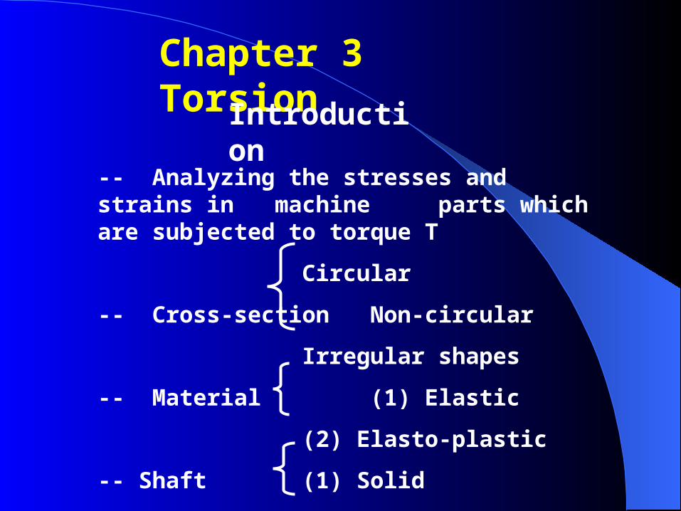
Chapter 3 Torsion
Introduction
-- Analyzing the stresses and strains in machine parts which are subjected to torque T
Circular
-- Cross-section Non-circular
Irregular shapes
-- Material (1) Elastic
(2) Elasto-plastic
-- Shaft (1) Solid
(2) Hollow
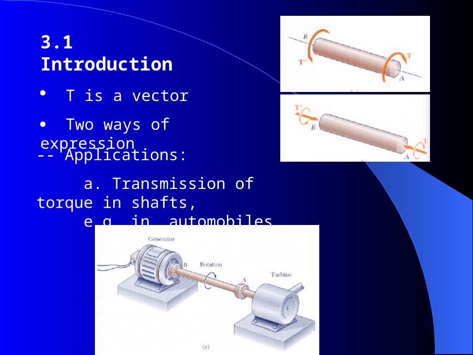
3.1 Introduction
T is a vector
Two ways of expression
-- Applications:
a. Transmission of torque in shafts, e.g. in automobiles

Assumptions in Torque Analysis:
a. Every cross section remains plane and undistorted.
b. Shearing strain varies linearly along the axis of the shaft.
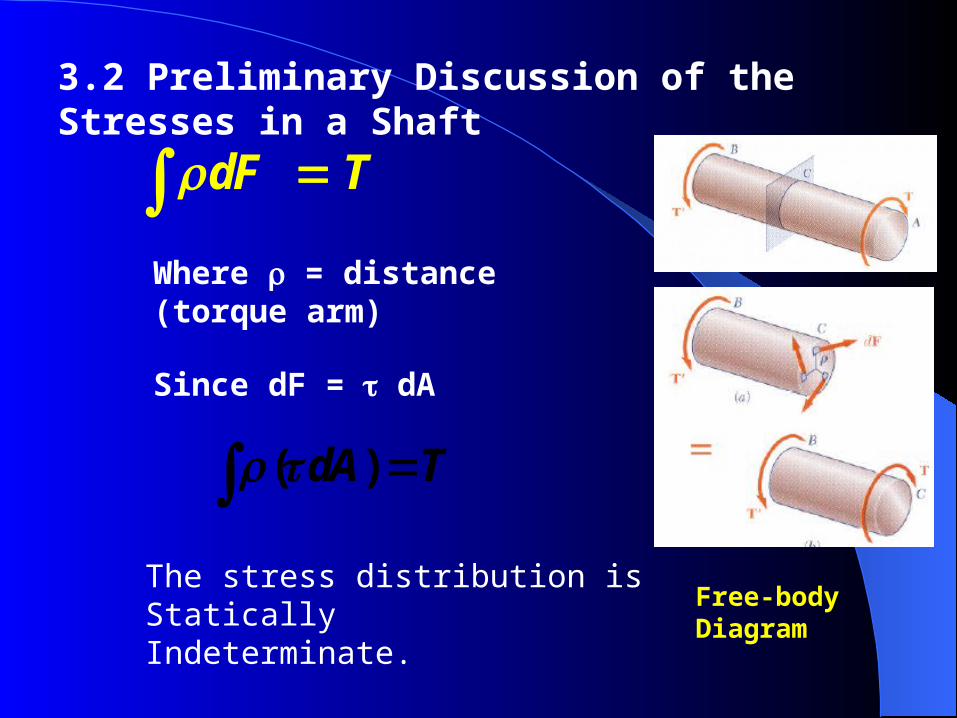
3.2 Preliminary Discussion of the Stresses in a Shaft
( ) dA T
dF T
Free-body Diagram
Where = distance (torque arm)
Since dF = dA
The stress distribution is Statically Indeterminate.
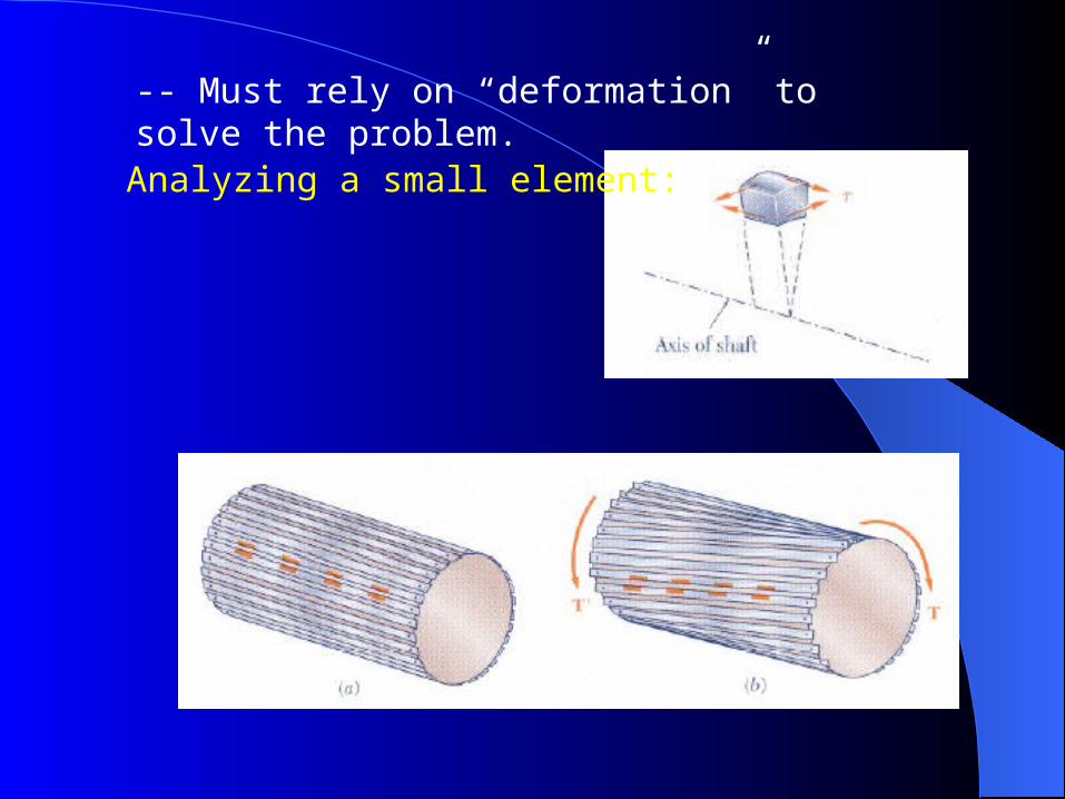
-- Must rely on “deformation” to solve the problem.
Analyzing a small element:
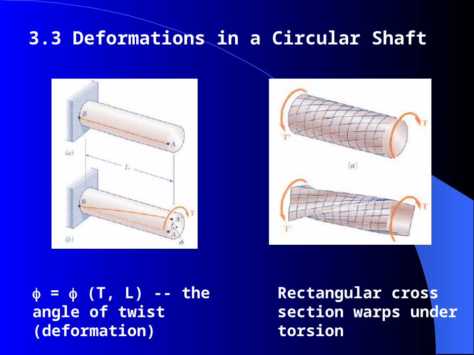
3.3 Deformations in a Circular Shaft
= (T, L) -- the angle of twist (deformation)
Rectangular cross section warps under torsion
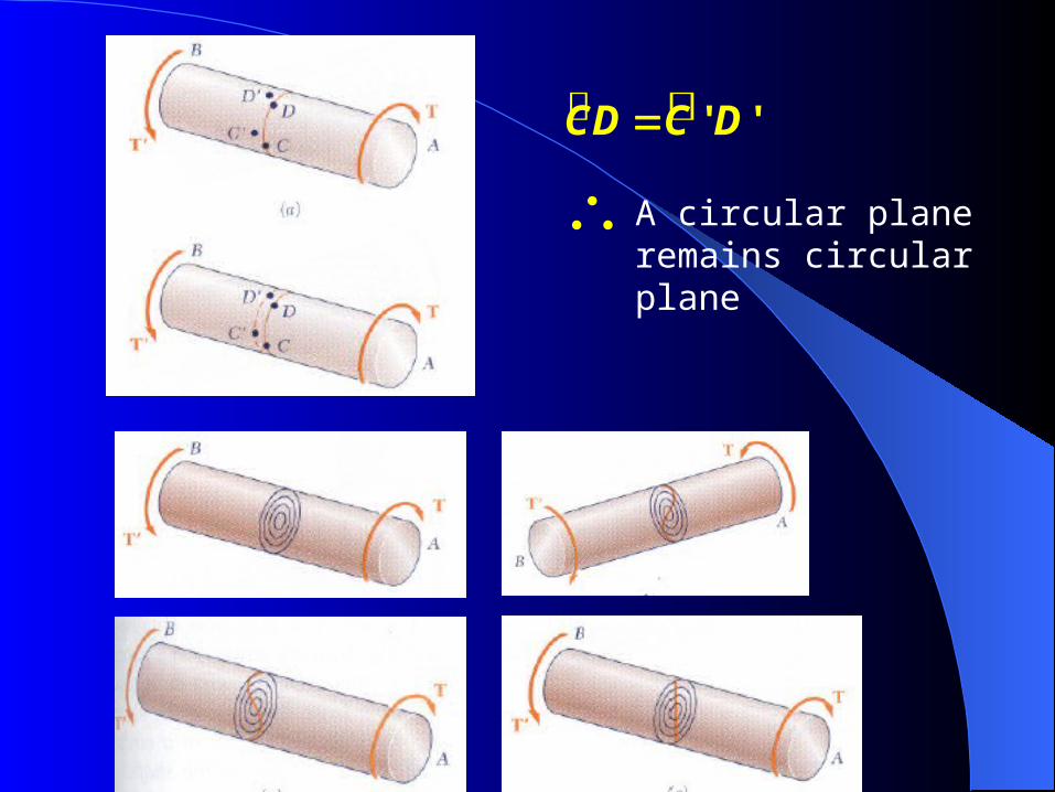
' 'CD C D
A circular plane remains circular plane
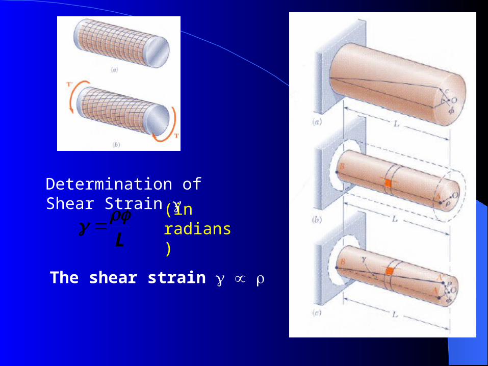
L (in radians)
Determination of Shear Strain
The shear strain
max
cL
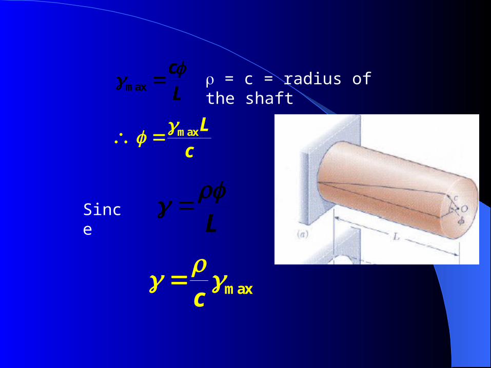
max
c
max L
c
= c = radius of the shaft
L Since
G
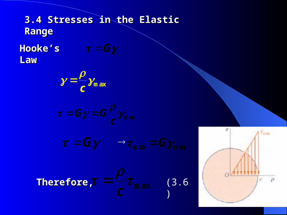
3.4 Stresses in the Elastic Range3.4 Stresses in the Elastic Range
Hooke’s LawHooke’s Law
max
c
max
G Gc
G max max G
max
c
Therefore, Therefore, (3.6)
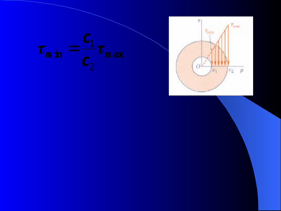
1
2min max
cc
max
JT
c
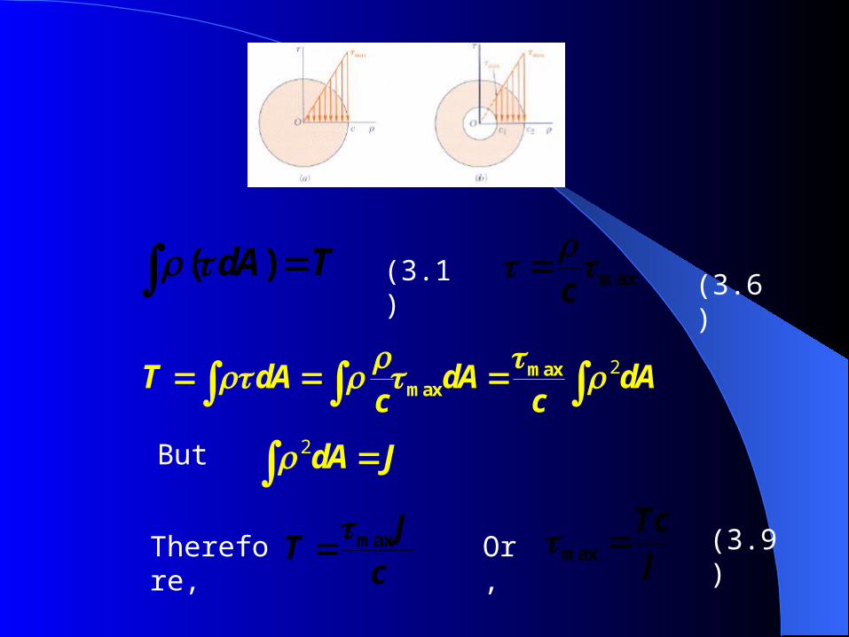
2maxmax
T dA dA dAc c
( ) dA T (3.1) max
c
(3.9)
But 2 dA J
Therefore, Or, max TcJ
(3.6)
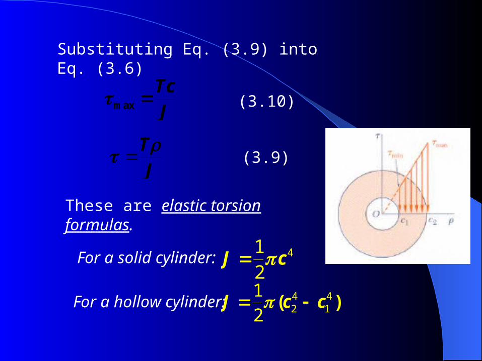
Substituting Eq. (3.9) into Eq. (3.6)
JT
max TcJ
412J c
(3.10)
(3.9)
These are elastic torsion formulas.
For a solid cylinder:
For a hollow cylinder: 4 42 1
12
( ) J c c
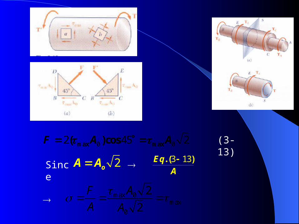
0 02 45 2max max( )cos F A A
2 oA A 3 13. ( )EqA
Since
max 0max
0
2
2
F A
A A
(3-13)
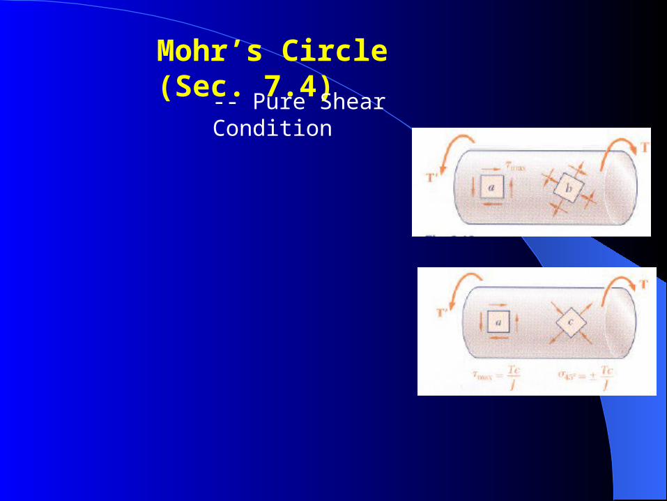
Mohr’s Circle (Sec. 7.4)
-- Pure Shear Condition
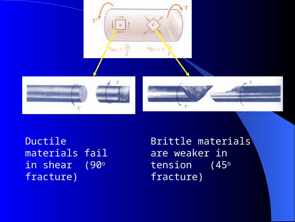
Ductile materials fail in shear (90o fracture)
Brittle materials are weaker in tension (45o fracture)
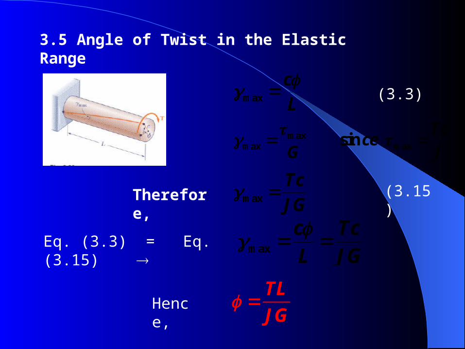
3.5 Angle of Twist in the Elastic Range
max
cL
maxmax maxsin
Tcce
G J
TL
JG
(3.3)
max
TcJG
(3.15)
max
c TcL JG Eq. (3.3) = Eq. (3.15)
Therefore,
Hence,
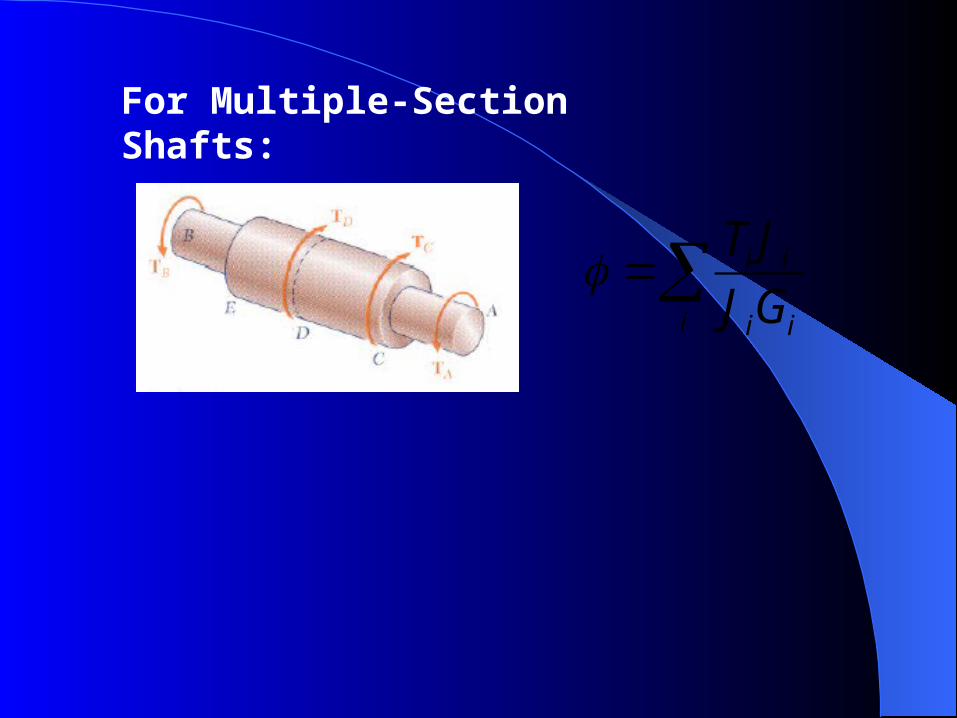
i i
i i i
T J
J G
For Multiple-Section Shafts:
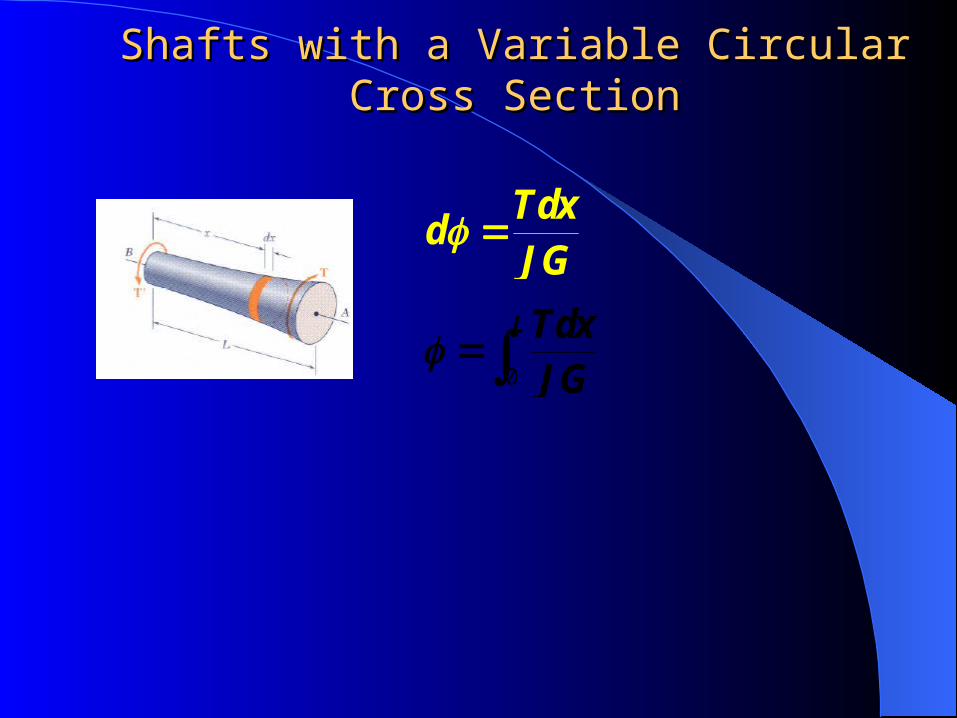
Shafts with a Variable Circular Cross SectionShafts with a Variable Circular Cross Section
0
LTdxJG
Tdx
dJG
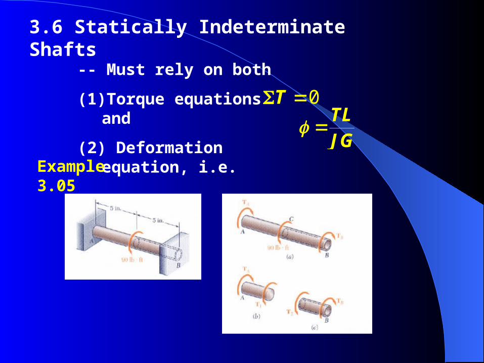
3.6 Statically Indeterminate Shafts
-- Must rely on both
(1) Torque equations and
(2) Deformation equation, i.e. TLJG
0T
Example 3.05
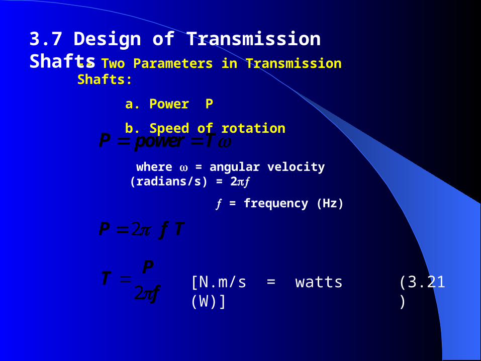
3.7 Design of Transmission Shafts
P power T
2P f T
fP
T2
-- Two Parameters in Transmission Shafts:
a. Power P
b. Speed of rotation
where = angular velocity (radians/s) = 2
= frequency (Hz)
[N.m/s = watts (W)] (3.21)
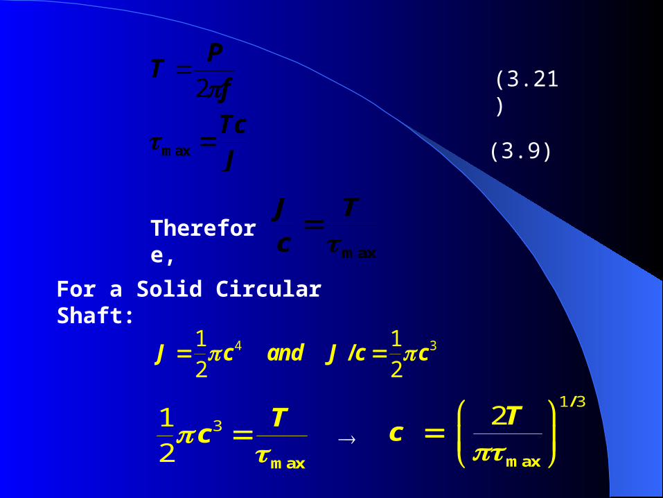
max TcJ
fP
T2
max
J Tc
(3.21)
(3.9)
4 31 12 2
/J c and J c c
For a Solid Circular Shaft:
Therefore,
312 max
Tc
1 32
/
max
Tc
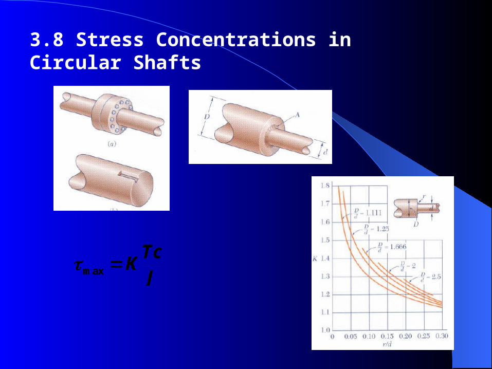
3.8 Stress Concentrations in Circular Shafts
max Tc
KJ
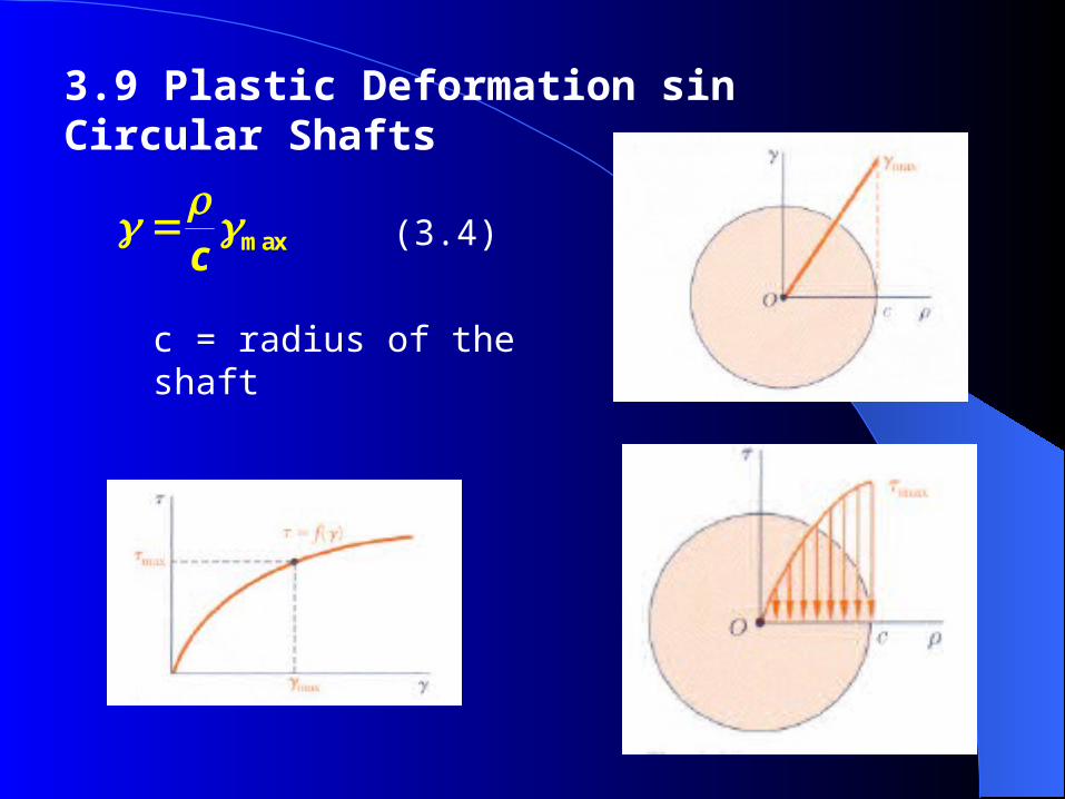
3.9 Plastic Deformation sin Circular Shafts
max
c
(3.4)
c = radius of the shaft
c
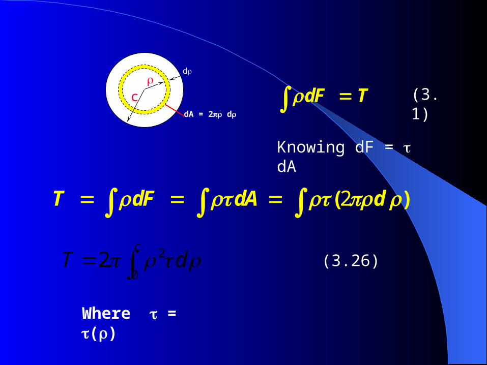
d
dA = 2 d
c
( )T dF dA d2
dF T (3.1)
Knowing dF = dA
2
02
cT d
Where = ()
(3.26)
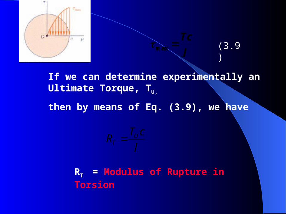
UT
T cR
J
max TcJ
(3.9)
If we can determine experimentally an Ultimate Torque, TU,
then by means of Eq. (3.9), we have
RT = Modulus of Rupture in Torsion
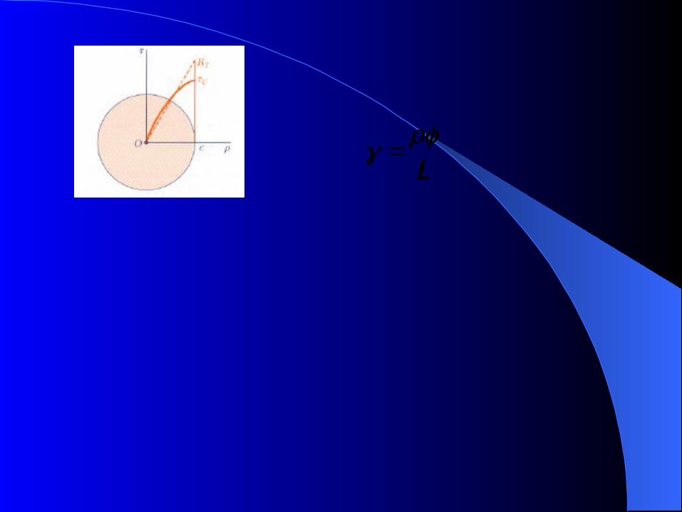
L
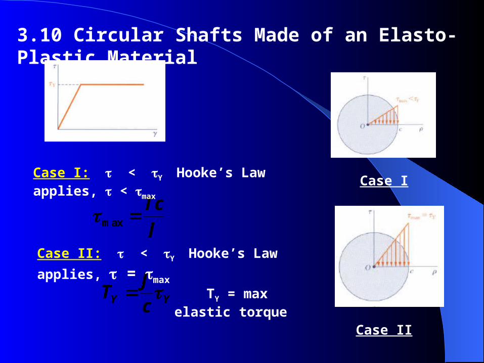
3.10 Circular Shafts Made of an Elasto-Plastic Material
Y Y
JT
c
max TcJ
Case I: < Y Hooke’s Law applies, < max Case I
Case II
Case II: < Y Hooke’s Law applies, = max
TY = max elastic torque
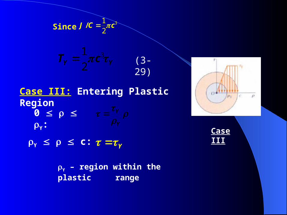
Since
Case III: Entering Plastic Region
312 Y YT c
312
/J C c
Y Case III
0 Y:
Y
Y
Y – region within the plastic range
Y c:
(3-29)
2
02
cT d
2 2
0
3 3 3
33
3
2 2
1 2 22 3 3
2 11
3 4( )
Y
Y
cY
elastic plastic YY
Y Y Y Y Y
YY
T T T d d
c
T cc
3
3
4 11
3 4( )
Y
YT Tc
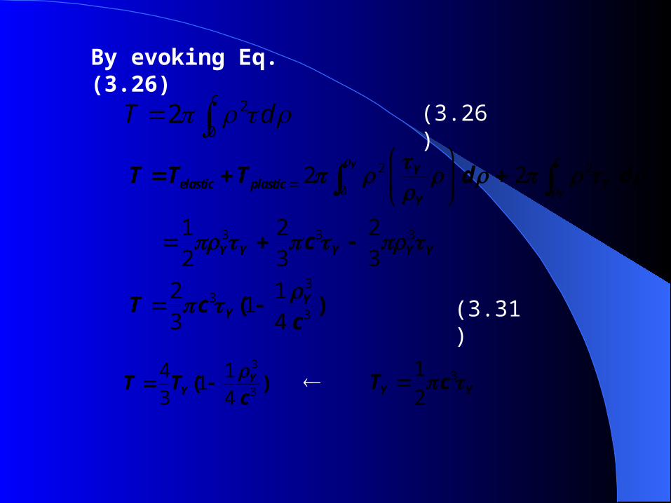
(3.26)
By evoking Eq. (3.26)
(3.31)
312 Y YT c
Case IV
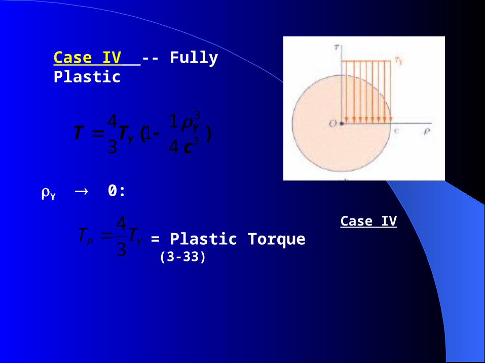
Case IV -- Fully Plastic
4
3P YT T
3
3
4 11
3 4( )
Y
YT Tc
Y 0:
= Plastic Torque (3-33)
YY
L
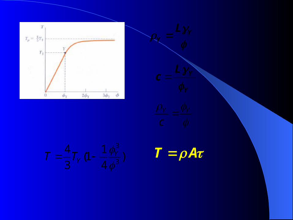
3
3
4 1(1 )
3 4 Y
YT T
Y Y
c
Y
YLc
T A
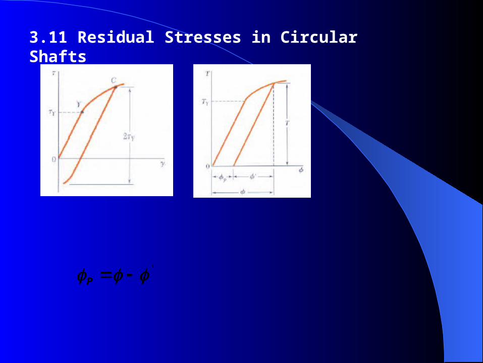
3.11 Residual Stresses in Circular Shafts
' P
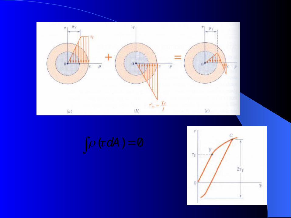
( ) 0 dA
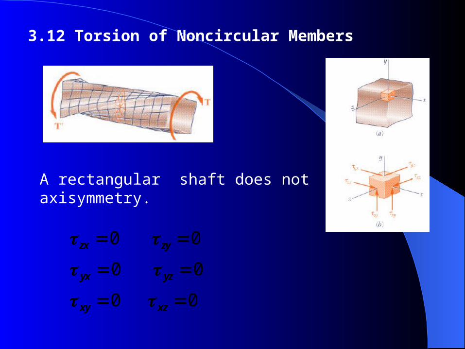
3.12 Torsion of Noncircular Members
0 0 yx yz
0 0 zx zy
0 0 xy xz
A rectangular shaft does not axisymmetry.
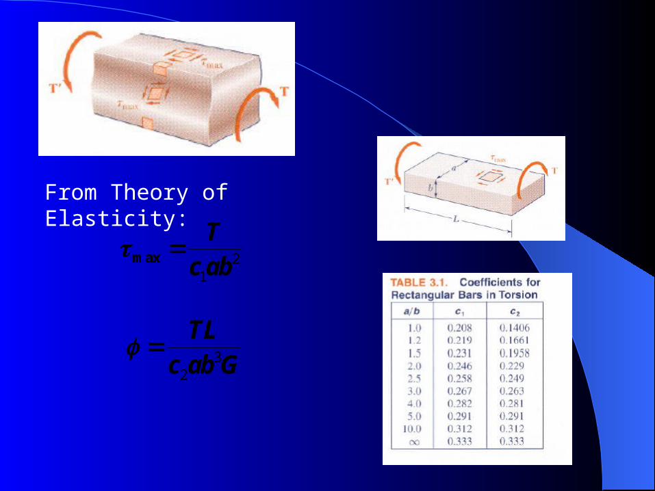
21
max Tc ab
32
TL
c ab G
From Theory of Elasticity:
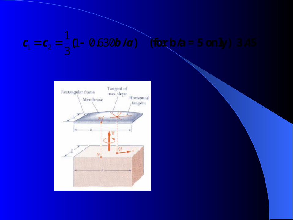
1 2
11 0 630
3( . / ) (for b/a = 5 only) 3.45 c c b a
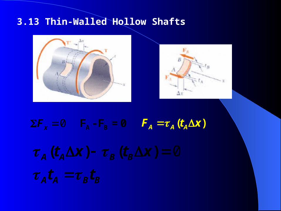
3.13 Thin-Walled Hollow Shafts
0 A BF - F = 0 xF ( ) A A AF t x
0( ) ( )
A A B B
A A B B
t x t x
t t
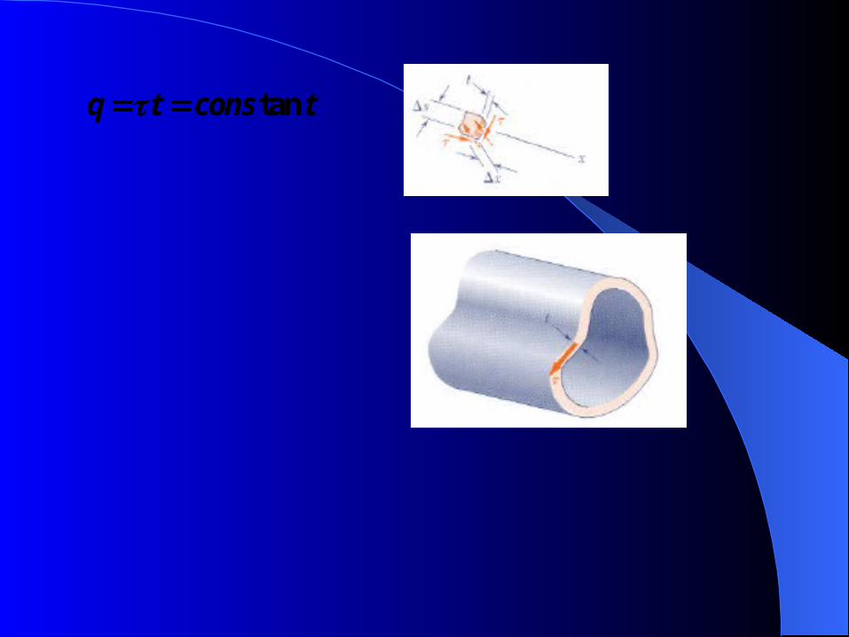
tan q t cons t
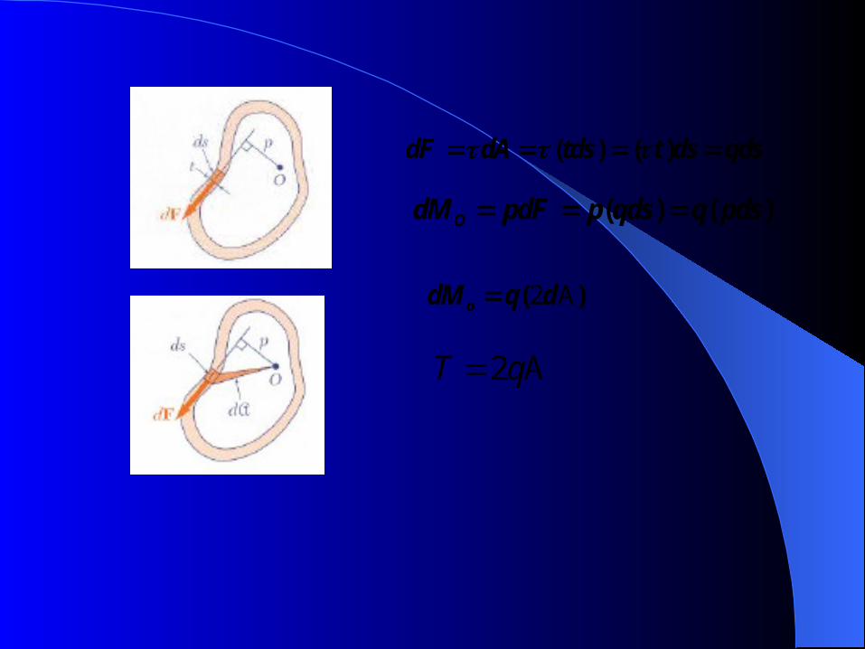
( ) ( ) dF dA tds t ds qds
( ) ( ) OdM pdF p qds q pds
2( )odM q dA
2T q A
24
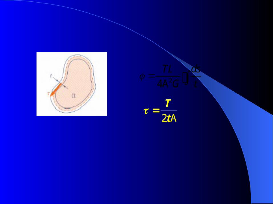
TL ds
G t A
2
TtA