Embed Size (px)
Citation preview
Mechanics of Materials 10ME34
Compiled by Hareesha N G, Asst Prof, DSCE Page 1
TABLE OF CONTENTS
TORSION OF CIRCULAR SHAFTS
8.1. INTRODUCTION ................................................................................................................................................ 2
8.2. PURE TORSION .................................................................................................................................................. 3
8.3. ASSUMPTIONS IN THE THEORY OF PURE TORSION ............................................................................. 3
8.4. DERIVATION OF TORSIONAL EQUATIONS .............................................................................................. 3
8.5. POLAR MODULUS ............................................................................................................................................. 5
8.6. TORSIONAL RIGIDITY / STIFFNESS OF SHAFTS ..................................................................................... 6
8.7. POWER TRANSMITTED .................................................................................................................................. 7
WORKED EXAMPLES ............................................................................................................................................. 7
ELASTIC STABILITY OF COLUMN
8.8. INTRODUCTION .............................................................................................................................................. 12
8.9. DEFINITIONS .................................................................................................................................................... 12
8.10. EULER'S FORMULA ..................................................................................................................................... 13
8.10.1. ASSUMPTIONS MADE IN EULER'S COLUMN THEORY .................................................................................... 13
8.10.2. SIGN CONVENTIONS ..................................................................................................................................... 13
8.10.2 EXPRESSION FOR CRIPPLING LOAD ............................................................................................................... 13
a) Both ends pinned (or hinged) ................................................................................................................... 14
b) One end fixed and other end free .............................................................................................................. 15
REFERENCES: ......................................................................................................................................................... 18
Mechanics of Materials 10ME34
Compiled by Hareesha N G, Asst Prof, DSCE Page 2
UNIT-8
TORSION OF CIRCULAR SHAFTS AND ELASTIC
STABILITY OF COLUMNS
Syllabus
Torsion:
Introduction, Pure torsion, assumptions, derivation of torsional equations, polar modulus,
torsional rigidity / stiffness of shafts, Power transmitted by solid and hollow circular shafts
Columns:
Euler's theory for axially loaded elastic long columns, Derivation of Euler's load for various end
conditions, limitations of Euler's theory, Rankine's formula
TORSION OF CIRCULAR SHAFTS
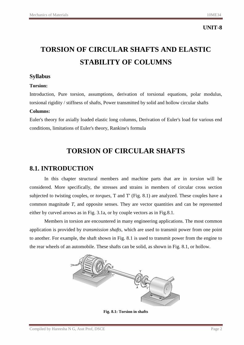
8.1. INTRODUCTION
In this chapter structural members and machine parts that are in torsion will be
considered. More specifically, the stresses and strains in members of circular cross section
subjected to twisting couples, or torques, T and T' (Fig. 8.1) are analyzed. These couples have a
common magnitude T, and opposite senses. They are vector quantities and can be represented
either by curved arrows as in Fig. 3.1a, or by couple vectors as in Fig.8.1.
Members in torsion are encountered in many engineering applications. The most common
application is provided by transmission shafts, which are used to transmit power from one point
to another. For example, the shaft shown in Fig. 8.1 is used to transmit power from the engine to
the rear wheels of an automobile. These shafts can be solid, as shown in Fig. 8.1, or hollow.
Fig. 8.1: Torsion in shafts
Mechanics of Materials 10ME34
Compiled by Hareesha N G, Asst Prof, DSCE Page 3
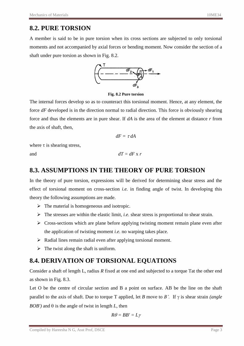
8.2. PURE TORSION
A member is said to be in pure torsion when its cross sections are subjected to only torsional
moments and not accompanied by axial forces or bending moment. Now consider the section of a
shaft under pure torsion as shown in Fig. 8.2.
Fig. 8.2 Pure torsion
The internal forces develop so as to counteract this torsional moment. Hence, at any element, the
force dF developed is in the direction normal to radial direction. This force is obviously shearing
force and thus the elements are in pure shear. If dA is the area of the element at distance r from
the axis of shaft, then,
dF = dA
where is shearing stress,
and dT = dF x r
8.3. ASSUMPTIONS IN THE THEORY OF PURE TORSION
In the theory of pure torsion, expressions will be derived for determining shear stress and the
effect of torsional moment on cross-section i.e. in finding angle of twist. In developing this
theory the following assumptions are made.
The material is homogeneous and isotropic.
The stresses are within the elastic limit, i.e. shear stress is proportional to shear strain.
Cross-sections which are plane before applying twisting moment remain plane even after
the application of twisting moment i.e. no warping takes place.
Radial lines remain radial even after applying torsional moment.
The twist along the shaft is uniform.
8.4. DERIVATION OF TORSIONAL EQUATIONS
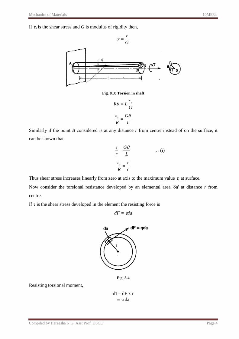
Consider a shaft of length L, radius R fixed at one end and subjected to a torque Tat the other end
as shown in Fig. 8.3.
Let O be the centre of circular section and B a point on surface. AB be the line on the shaft
parallel to the axis of shaft. Due to torque T applied, let B move to B’. If is shear strain (angle
BOB') and is the angle of twist in length L, then
R = BB' = L
Mechanics of Materials 10ME34
Compiled by Hareesha N G, Asst Prof, DSCE Page 4
If s is the shear stress and G is modulus of rigidity then,
G
Fig. 8.3: Torsion in shaft
GLR s
L
G
R
s
Similarly if the point B considered is at any distance r from centre instead of on the surface, it
can be shown that
L
G
r
… (i)
rR
s
Thus shear stress increases linearly from zero at axis to the maximum value s at surface.
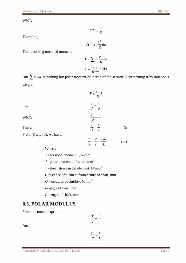
Now consider the torsional resistance developed by an elemental area 'a' at distance r from
centre.
If is the shear stress developed in the element the resisting force is
dF = da
Fig. 8.4
Resisting torsional moment,
dT= dF x r
rda
Mechanics of Materials 10ME34
Compiled by Hareesha N G, Asst Prof, DSCE Page 5
WKT,
R
rs
Therefore,
daR
rdT s
2
Total resisting torsional moment,
daR
rT s
2
darR
T s 2
But dar 2 is nothing but polar moment of inertia of the section. Representing it by notation J
we get,
JR
T s
i.e., RJ
T s
WKT, rR
s
There, rJ
T (ii)
From (i) and (ii), we have,
L
G
rJ
T (iii)
Where,
T - torsional moment , N-mm
J - polar moment of inertia, mm4
- shear stress in the element, N/mm2
r- distance of element from centre of shaft, mm
G - modulus of rigidity, N/mm2
- angle of twist, rad
L- length of shaft, mm
8.5. POLAR MODULUS
From the torsion equation,
rJ
T
But,
rR
s
Mechanics of Materials 10ME34
Compiled by Hareesha N G, Asst Prof, DSCE Page 6
Where s is maximum shear stress (occurring at surface) and R is extreme fibre distance from
centre. Therefore,
RJ
T s
or
sps ZR
JT
where Zp is called as 'Polar Modulus of Section’. It may be observed that Zp is the property of the
section and may be defined as the ratio of polar moment of inertia to extreme radial distance of
the fibre from the centre.
(i) For solid circular section of diameter d
J R
(ii) For hollow circular shaft with external diameter d1 and internal diameter d2
8.6. TORSIONAL RIGIDITY / STIFFNESS OF SHAFTS
From the torsion equation,
Angle of twist, GJ
TL
T - Torsional moment , N-mm
J - Polar moment of inertia, mm4
G - Modulus of rigidity, N/mm2
(sometimes denoted by C)
- angle of twist, rad
For a given specimen, the shaft properties like length L, polar modulus J and material
properties like rigidity modulus G are constants and hence the angle of twist is directly
proportional to the twisting moment or torque producing the twist. Torque producing twist in a
shaft is similar to the bending moment producing bend or deflection in a beam. Similar to the
flexural rigidity in beams expressed by EI, torsional rigidity is expressed as GJ which can be
defined as the torque required to produce a twist of unit radian per unit length of the shaft.
Mechanics of Materials 10ME34
Compiled by Hareesha N G, Asst Prof, DSCE Page 7
8.7. POWER TRANSMITTED
Let us consider a circular shaft running at N rpm under mean torque T. Let P be the power
transmitted by the shaft in kW.
The angular speed of the shaft is given by the distance covered by a particle in the circle in
radians for N revolutions per second, i.e. the particle covers radians for one revolution and for
N revolutions the particle covers 2N radians in one minute. Hence the angular speed is given
by:
60
2 N Rad/s
Thus, the power transmitted = Mean torque (kN-m) x Angular speed (rad/s)
i.e.,
60
2 NTTP
kN-m/s or kW
It is seen that from the above equation mean torque T in kN-m is obtained. It should be converted
to N-mm so that the stress due to torque can be obtained in N/mm2. Maximum shear stress due to
torque can be obtained from the torque equation.
L
G
rJ
T
WORKED EXAMPLES
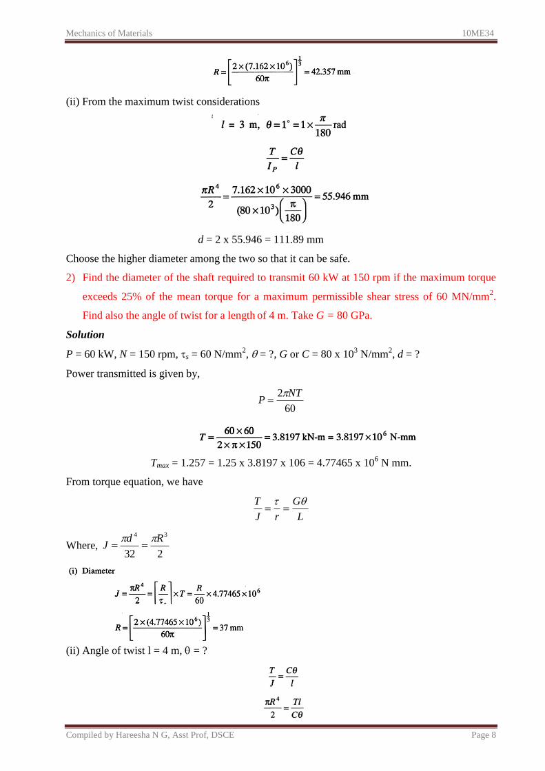
1) A solid shaft has to transmit 120 kW of power at 160 rpm. If the shear stress is not to exceed
60 MPa and the twist in a length of 3 m must not exceed 1°, find the suitable diameter of the
shaft. Take G = 80 GPa.
Solution
P = 120 kW, N = 160 rpm, = 60 N/mm2, = 1°, G or C = 80 x 10
3 N/mm
2, d = ?
Power transmitted is given by,
(i) From the maximum shear stress considerations
Mechanics of Materials 10ME34
Compiled by Hareesha N G, Asst Prof, DSCE Page 8
(ii) From the maximum twist considerations
d = 2 x 55.946 = 111.89 mm
Choose the higher diameter among the two so that it can be safe.
2) Find the diameter of the shaft required to transmit 60 kW at 150 rpm if the maximum torque
exceeds 25% of the mean torque for a maximum permissible shear stress of 60 MN/mm2.
Find also the angle of twist for a length of 4 m. Take G = 80 GPa.
Solution
P = 60 kW, N = 150 rpm, s = 60 N/mm2, = ?, G or C = 80 x 10
3 N/mm
2, d = ?
Power transmitted is given by,
60
2 NTP
Tmax = 1.257 = 1.25 x 3.8197 x 106 = 4.77465 x 10⁶ N mm.
From torque equation, we have
L
G
rJ
T
Where, 232
34 RdJ
(ii) Angle of twist l = 4 m, = ?
Mechanics of Materials 10ME34
Compiled by Hareesha N G, Asst Prof, DSCE Page 9
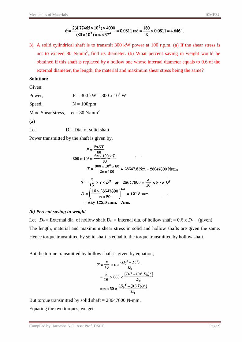
3) A solid cylindrical shaft is to transmit 300 kW power at 100 r.p.m. (a) If the shear stress is
not to exceed 80 N/mm2, find its diameter. (b) What percent saving in weight would be
obtained if this shaft is replaced by a hollow one whose internal diameter equals to 0.6 of the
external diameter, the length, the material and maximum shear stress being the same?
Solution:
Given:
Power, P = 300 kW = 300 x 103 W
Speed, N = 100rpm
Max. Shear stress, = 80 N/mm2
(a)
Let D = Dia. of solid shaft
Power transmitted by the shaft is given by,
(b) Percent saving in weight
Let D0 = External dia. of hollow shaft Di. = Internal dia. of hollow shaft = 0.6 x Do. (given)
The length, material and maximum shear stress in solid and hollow shafts are given the same.
Hence torque transmitted by solid shaft is equal to the torque transmitted by hollow shaft.
But the torque transmitted by hollow shaft is given by equation,
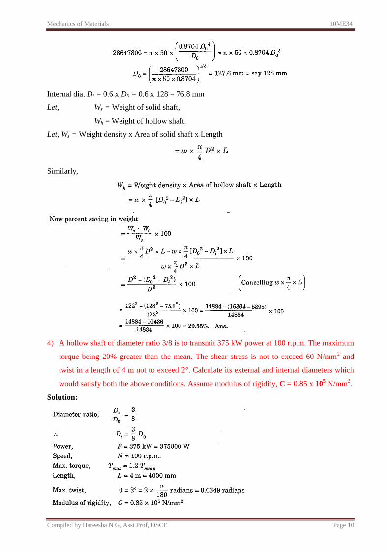
But torque transmitted by solid shaft = 28647800 N-mm.
Equating the two torques, we get
Mechanics of Materials 10ME34
Compiled by Hareesha N G, Asst Prof, DSCE Page 10
Internal dia, Di = 0.6 x D0 = 0.6 x 128 = 76.8 mm
Let, Ws = Weight of solid shaft,
Wh = Weight of hollow shaft.
Let, Ws = Weight density x Area of solid shaft x Length
Similarly,
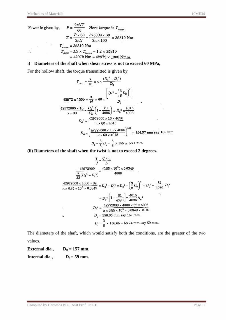
4) A hollow shaft of diameter ratio 3/8 is to transmit 375 kW power at 100 r.p.m. The maximum
torque being 20% greater than the mean. The shear stress is not to exceed 60 N/mm2 and
twist in a length of 4 m not to exceed 2°. Calculate its external and internal diameters which
would satisfy both the above conditions. Assume modulus of rigidity, C = 0.85 x 10⁵ N/mm
2.
Solution:
Mechanics of Materials 10ME34
Compiled by Hareesha N G, Asst Prof, DSCE Page 11
i) Diameters of the shaft when shear stress is not to exceed 60 MPa,
For the hollow shaft, the torque transmitted is given by
(ii) Diameters of the shaft when the twist is not to exceed 2 degrees.
The diameters of the shaft, which would satisfy both the conditions, are the greater of the two
values.
External dia., D0 = 157 mm.
Internal dia., Di = 59 mm.
Mechanics of Materials 10ME34
Compiled by Hareesha N G, Asst Prof, DSCE Page 12
ELASTIC STABILITY OF COLUMNS
8.8. INTRODUCTION
Buckling is characterized by a sudden sideways failure of a structural member subjected
to high compressive stress, where the compressive stress at the point of failure is less than the
ultimate compressive stress that the material is capable of withstanding. Mathematical analysis of
buckling often makes use of an "artificial" axial load eccentricity that introduces a secondary
bending moment that is not a part of the primary applied forces being studied. As an applied load
is increased on a member, such as a column, it will ultimately become large enough to cause the
member to become unstable and is said to have buckled. Further load will cause significant and
somewhat unpredictable deformations, possibly leading to complete loss of the member's load-
carrying capacity. If the deformations that follow buckling are not catastrophic the member will
continue to carry the load that caused it to buckle. If the buckled member is part of a larger
assemblage of components such as a building, any load applied to the structure beyond that
which caused the member to buckle will be redistributed within the structure.
8.9. DEFINITIONS
Column: A vertical slender bar or member subjected to an axial compressive load is called a
column.
Strut: A slender bar or member in any position other than vertical, subjected to an axial
compressive load, is called a strut.
Slenderness ratio: It is the ratio of the length of the column to the minimum radius of gyration
of the cross-sectional area of the column.
Buckling factor: The ratio between the equivalent lengths of the column to the minimum radius
of gyration is called the buckling factor.
Buckling Load: When the axial load increases continuously on a column, at a certain value of
the load, the column will just slightly be deflected or a little lateral displacement will take place
in it. At this position, the internal forces which tend to straighten the column are just equal to the
applied load. The minimum limiting load at which the column tends to have lateral displacement
or tends to buckle, is called a buckling or crippling or critical load. Buckling takes place about
the axis having minimum radius of gyration or least moment of inertia.
Safe load: The load to which a column is subjected and which is below the buckling load is
called the safe load. It is obtained by dividing the buckling load by a suitable factor of safety.
Mechanics of Materials 10ME34
Compiled by Hareesha N G, Asst Prof, DSCE Page 13
8.10. EULER'S FORMULA
In 1757, Swiss mathematician Leonhard Euler first analysed the long columns
mathematically ignoring the effect of direct stress, and determined critical loads that
would cause failure due to buckling only. His analysis is based on certain assumptions.
8.10.1. Assumptions Made in Euler's Column Theory
The following assumptions are made in the Euler's column theory:
The column is initially perfectly straight and the load is applied axially.
The cross-section of the column is uniform throughout its length.
The column material is perfectly elastic, homogeneous, isotropic and obeys Hooke's law.
The length of the column is very large as compared to its lateral dimensions.
The direct stress is very small as compared to the bending stress.
The column will fail by buckling alone.
The self-weight of column is negligible.
8.10.2. Sign Conventions
The following sign conventions for the bending of the columns will be used:
A moment which will bend the column with its convexity towards its initial central line is
taken as positive
A moment which will tend to bend the column with its concavity towards its initial centre
line is taken as negative.
8.10.2 Expression for Crippling Load
In this section, we will derive expressions for buckling loads on columns with following
end conditions:
Both ends pinned (or hinged)
One end fixed and other end free
Both ends fixed
One end fixed and other end hinged
Mechanics of Materials 10ME34
Compiled by Hareesha N G, Asst Prof, DSCE Page 14
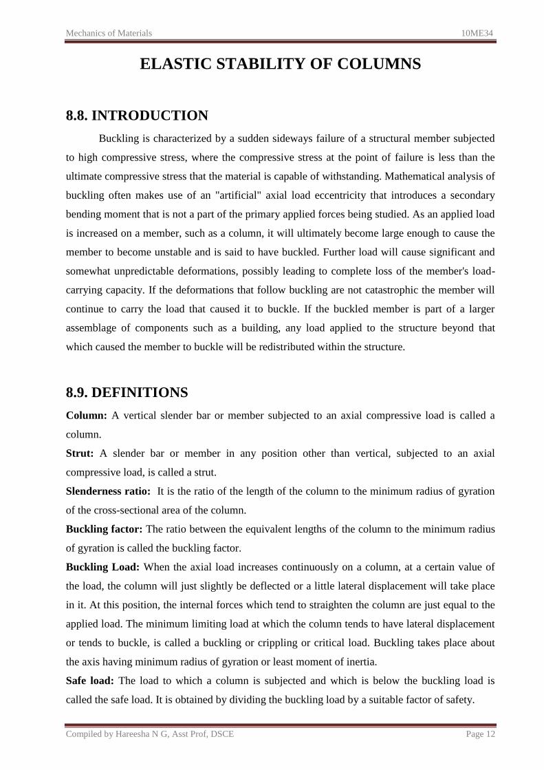
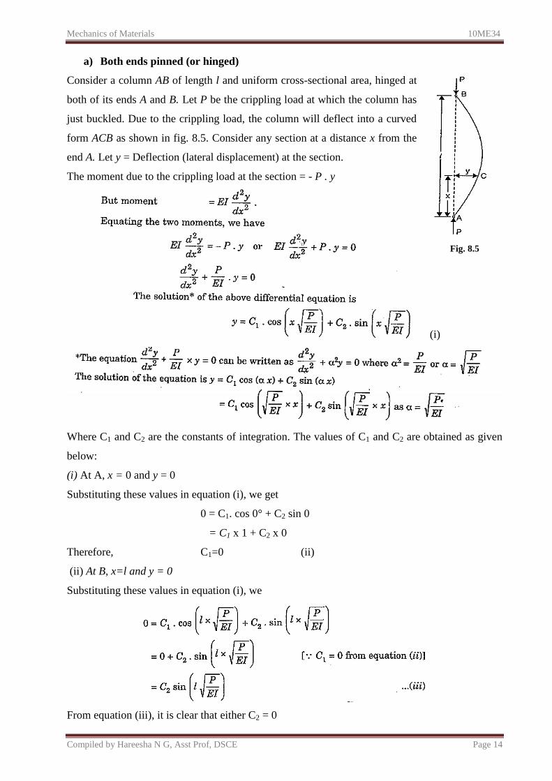
a) Both ends pinned (or hinged)
Consider a column AB of length l and uniform cross-sectional area, hinged at
both of its ends A and B. Let P be the crippling load at which the column has
just buckled. Due to the crippling load, the column will deflect into a curved
form ACB as shown in fig. 8.5. Consider any section at a distance x from the
end A. Let y = Deflection (lateral displacement) at the section.
The moment due to the crippling load at the section = - P . y
Fig. 8.5
(i)
Where C1 and C2 are the constants of integration. The values of C1 and C2 are obtained as given
below:
(i) At A, x = 0 and y = 0
Substituting these values in equation (i), we get
0 = C1. cos 0° + C2 sin 0
= C1 x 1 + C2 x 0
Therefore, C1=0 (ii)
(ii) At B, x=l and y = 0
Substituting these values in equation (i), we
From equation (iii), it is clear that either C2 = 0
Mechanics of Materials 10ME34
Compiled by Hareesha N G, Asst Prof, DSCE Page 15
As C1 = 0, then if C2 is also equal to zero, then from equation (i) we will get y = 0. This means
that the bending of the column will be zero or the column will not bend at all. This is not true.
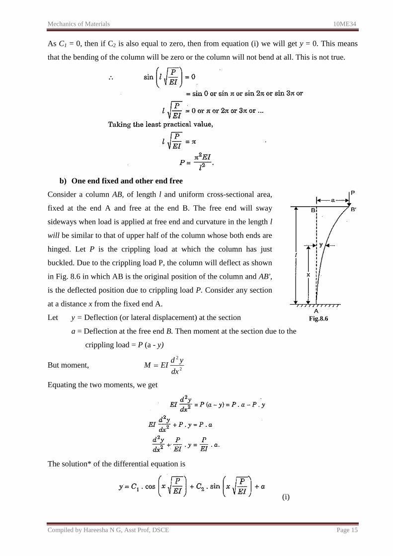
b) One end fixed and other end free
Consider a column AB, of length l and uniform cross-sectional area,
fixed at the end A and free at the end B. The free end will sway
sideways when load is applied at free end and curvature in the length l
will be similar to that of upper half of the column whose both ends are
hinged. Let P is the crippling load at which the column has just
buckled. Due to the crippling load P, the column will deflect as shown
in Fig. 8.6 in which AB is the original position of the column and AB',
is the deflected position due to crippling load P. Consider any section
at a distance x from the fixed end A.
Let y = Deflection (or lateral displacement) at the section
Fig.8.6
a = Deflection at the free end B. Then moment at the section due to the
crippling load = P (a - y)
But moment, 2
2
dx
ydEIM
Equating the two moments, we get
The solution* of the differential equation is
(i)
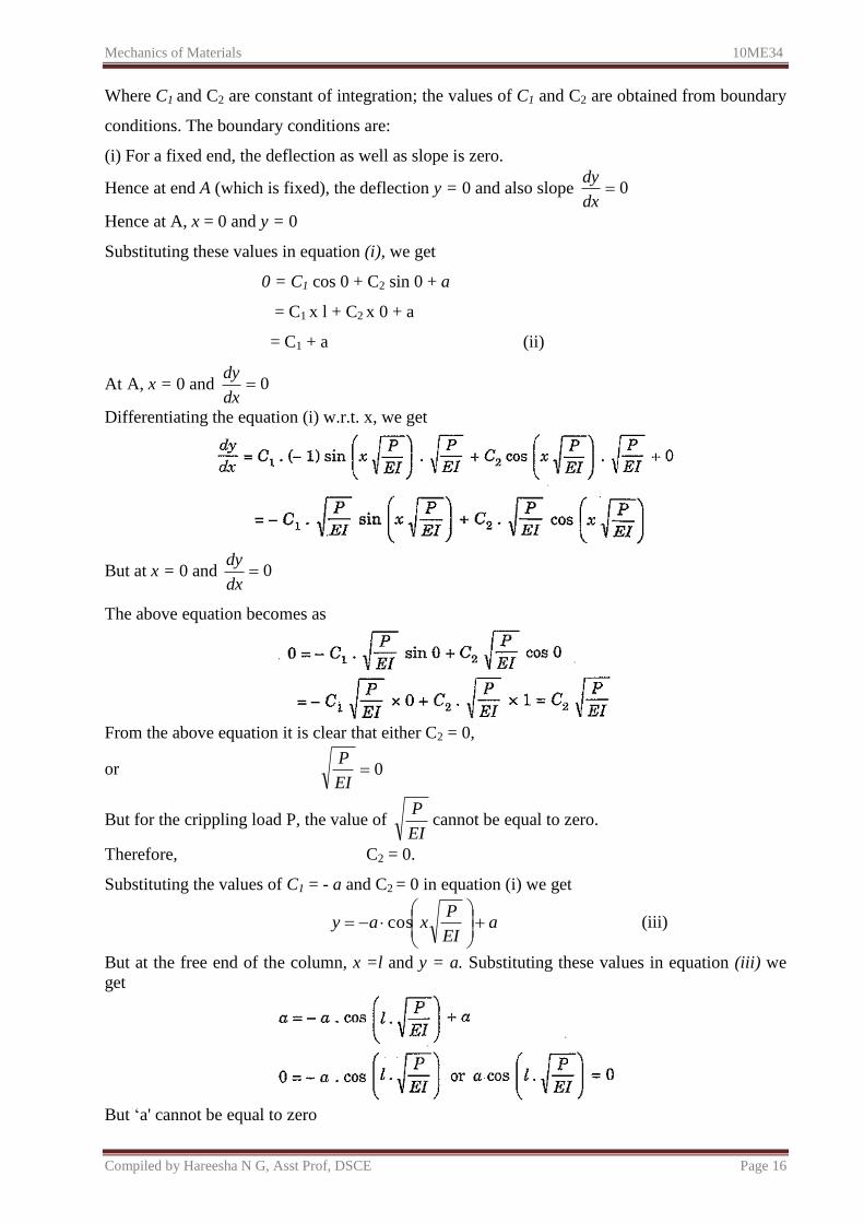
Mechanics of Materials 10ME34
Compiled by Hareesha N G, Asst Prof, DSCE Page 16
Where C1 and C2 are constant of integration; the values of C1 and C2 are obtained from boundary
conditions. The boundary conditions are:
(i) For a fixed end, the deflection as well as slope is zero.
Hence at end A (which is fixed), the deflection y = 0 and also slope 0dx
dy
Hence at A, x = 0 and y = 0
Substituting these values in equation (i), we get
0 = C1 cos 0 + C2 sin 0 + a
= C1 x l + C2 x 0 + a
= C1 + a (ii)
At A, x = 0 and 0dx
dy
Differentiating the equation (i) w.r.t. x, we get
But at x = 0 and 0dx
dy
The above equation becomes as
From the above equation it is clear that either C2 = 0,
or 0EI
P
But for the crippling load P, the value of EI
Pcannot be equal to zero.
Therefore, C2 = 0.
Substituting the values of C1 = - a and C2 = 0 in equation (i) we get
aEI
Pxay
cos (iii)
But at the free end of the column, x =l and y = a. Substituting these values in equation (iii) we
get
But ‘a' cannot be equal to zero
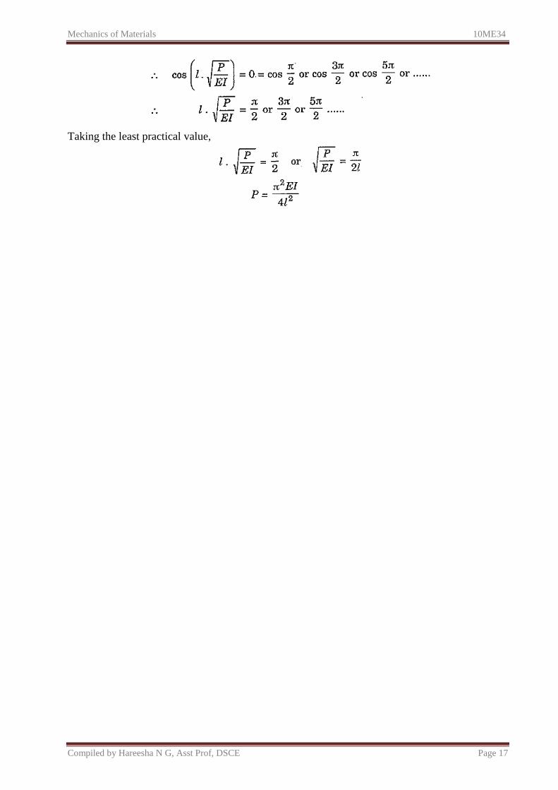
Mechanics of Materials 10ME34
Compiled by Hareesha N G, Asst Prof, DSCE Page 17
Taking the least practical value,
Mechanics of Materials 10ME34
Compiled by Hareesha N G, Asst Prof, DSCE Page 18
REFERENCES:
1) A Textbook of Strength of Materials By R. K. Bansal
2) Fundamentals Of Strength Of Materials By P. N. Chandramouli
3) Strength of Materials By B K Sarkar
4) Strength of Materials S S Bhavikatti
5) Textbook of Mechanics of Materials by Prakash M. N. Shesha, suresh G. S.
6) Mechanics of Materials: with programs in C by M. A. Jayaram