Embed Size (px)
Citation preview
Chapter 3
STEADY HEAT CONDUCTION
Copyright © The McGraw-Hill Companies, Inc. Permission required for reproduction or display.
Heat and Mass Transfer: Fundamentals & Applications
5th Edition in SI Units
Yunus A. Çengel, Afshin J. Ghajar
McGraw-Hill, 2015
Mehmet Kanoglu
University of Gaziantep
2
Objectives
• Understand the concept of thermal resistance and its
limitations, and develop thermal resistance networks for
practical heat conduction problems
• Solve steady conduction problems that involve multilayer
rectangular, cylindrical, or spherical geometries
• Develop an intuitive understanding of thermal contact
resistance, and circumstances under which it may be
significant
• Identify applications in which insulation may actually
increase heat transfer
• Analyze finned surfaces, and assess how efficiently and
effectively fins enhance heat transfer
• Solve multidimensional practical heat conduction problems
using conduction shape factors
3
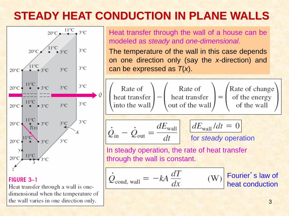
STEADY HEAT CONDUCTION IN PLANE WALLS
for steady operation
In steady operation, the rate of heat transfer
through the wall is constant.
Fourier’s law of
heat conduction
Heat transfer through the wall of a house can be
modeled as steady and one-dimensional.
The temperature of the wall in this case depends
on one direction only (say the x-direction) and
can be expressed as T(x).
4
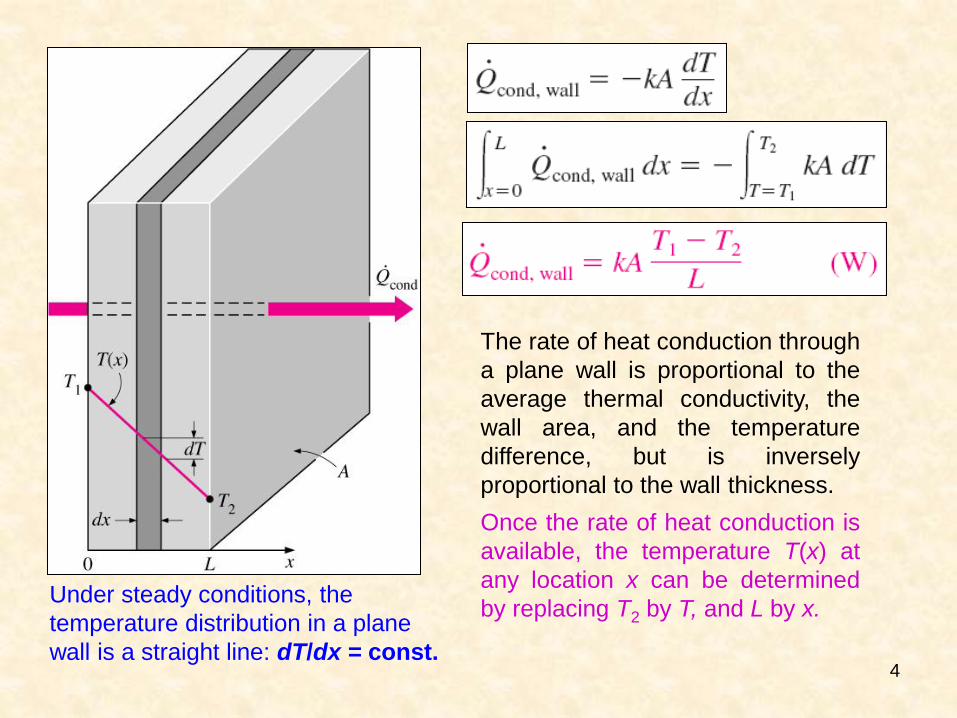
Under steady conditions, the
temperature distribution in a plane
wall is a straight line: dT/dx = const.
The rate of heat conduction through
a plane wall is proportional to the
average thermal conductivity, the
wall area, and the temperature
difference, but is inversely
proportional to the wall thickness.
Once the rate of heat conduction is
available, the temperature T(x) at
any location x can be determined
by replacing T2 by T, and L by x.
5
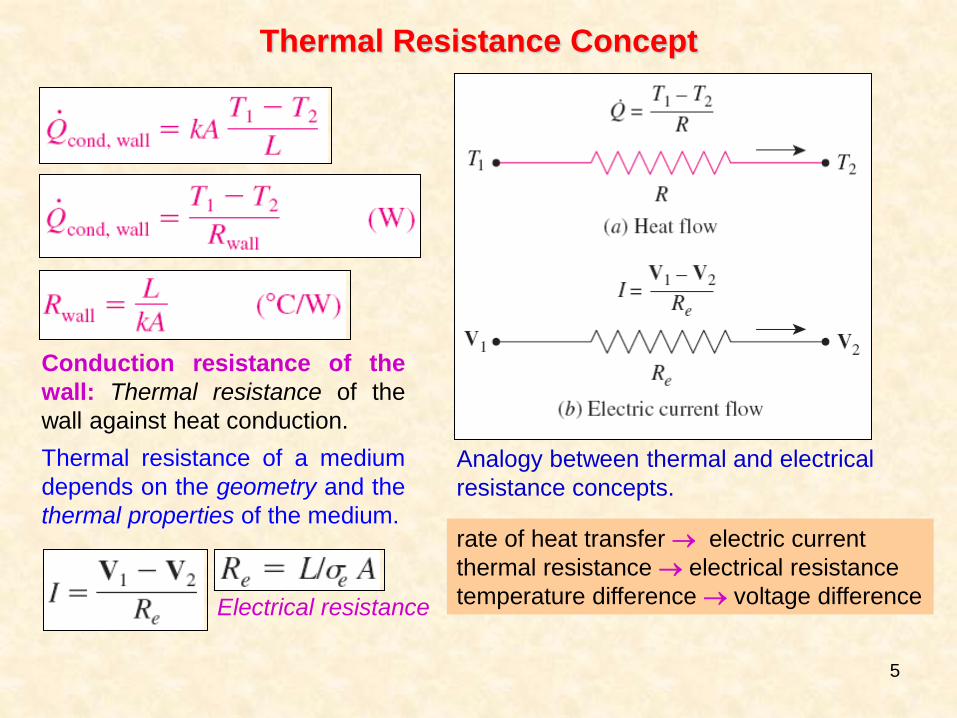
Analogy between thermal and electrical
resistance concepts.
rate of heat transfer electric current
thermal resistance electrical resistance
temperature difference voltage difference
Thermal Resistance Concept
Conduction resistance of the
wall: Thermal resistance of the
wall against heat conduction.
Thermal resistance of a medium
depends on the geometry and the
thermal properties of the medium.
Electrical resistance
6
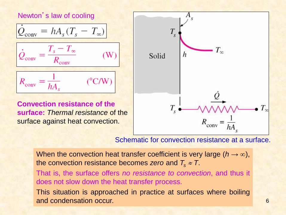
Schematic for convection resistance at a surface.
Newton’s law of cooling
Convection resistance of the
surface: Thermal resistance of the
surface against heat convection.
When the convection heat transfer coefficient is very large (h → ),
the convection resistance becomes zero and Ts T.
That is, the surface offers no resistance to convection, and thus it
does not slow down the heat transfer process.
This situation is approached in practice at surfaces where boiling
and condensation occur.
7
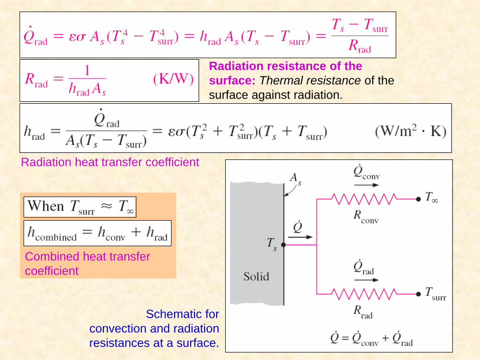
Radiation resistance of the
surface: Thermal resistance of the
surface against radiation.
Schematic for
convection and radiation
resistances at a surface.
Radiation heat transfer coefficient
Combined heat transfer
coefficient
8
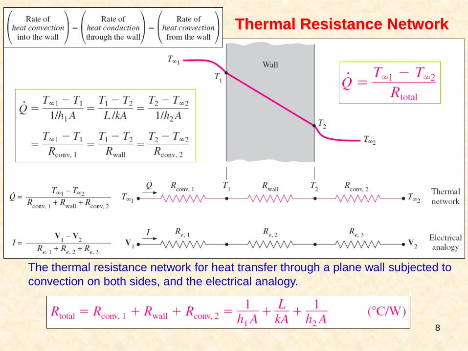
Thermal Resistance Network
The thermal resistance network for heat transfer through a plane wall subjected to
convection on both sides, and the electrical analogy.
9
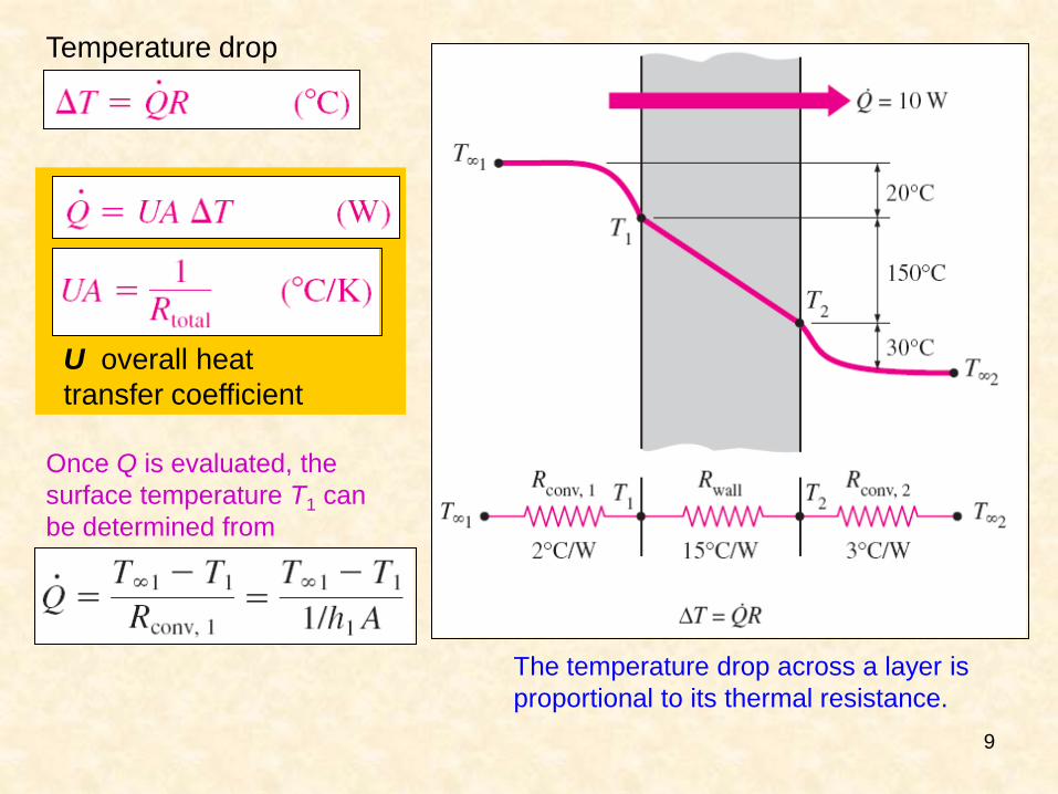
U overall heat
transfer coefficient
Once Q is evaluated, the
surface temperature T1 can
be determined from
Temperature drop
The temperature drop across a layer is
proportional to its thermal resistance.
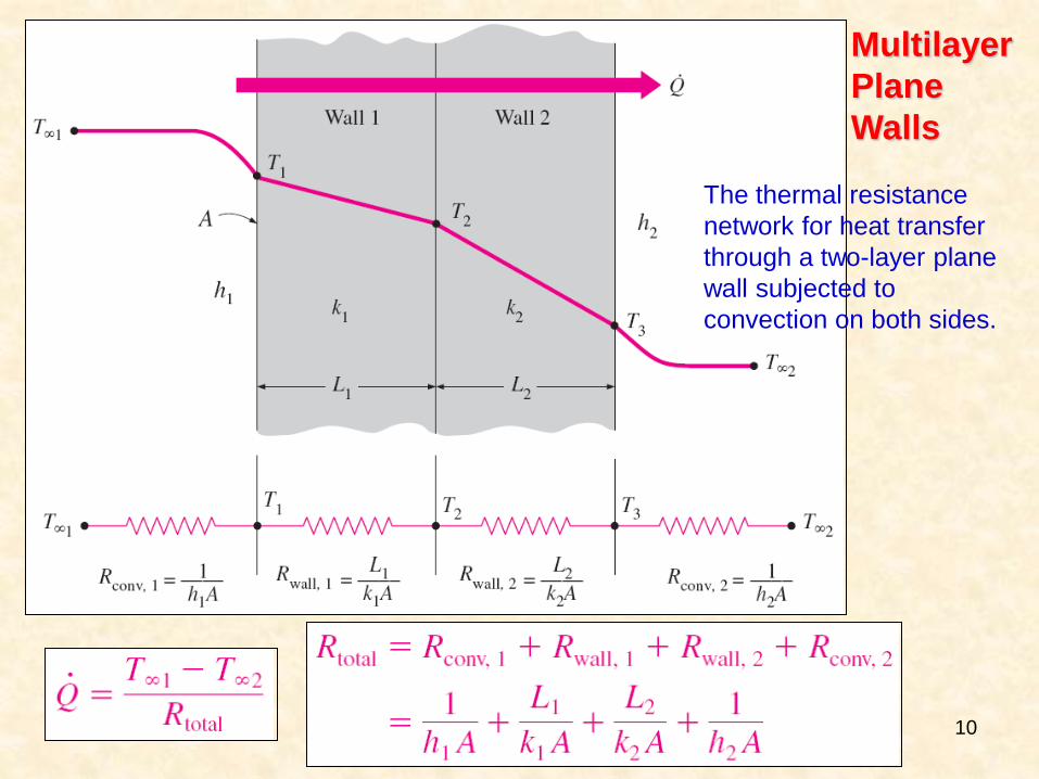
10
The thermal resistance
network for heat transfer
through a two-layer plane
wall subjected to
convection on both sides.
Multilayer
Plane
Walls
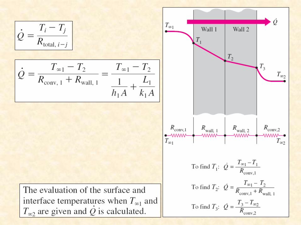
11
12
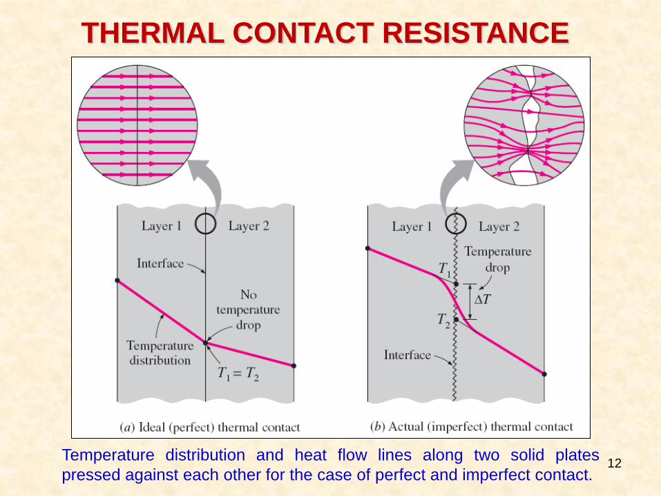
THERMAL CONTACT RESISTANCE
Temperature distribution and heat flow lines along two solid plates
pressed against each other for the case of perfect and imperfect contact.
13
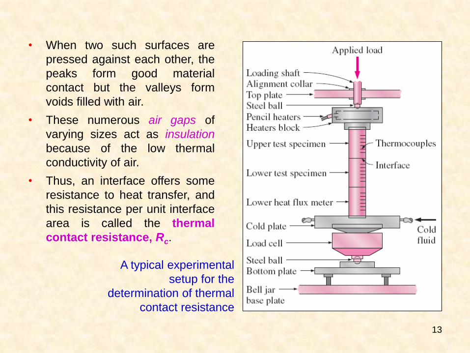
A typical experimental
setup for the
determination of thermal
contact resistance
• When two such surfaces are
pressed against each other, the
peaks form good material
contact but the valleys form
voids filled with air.
• These numerous air gaps of
varying sizes act as insulation
because of the low thermal
conductivity of air.
• Thus, an interface offers some
resistance to heat transfer, and
this resistance per unit interface
area is called the thermal
contact resistance, Rc.
14
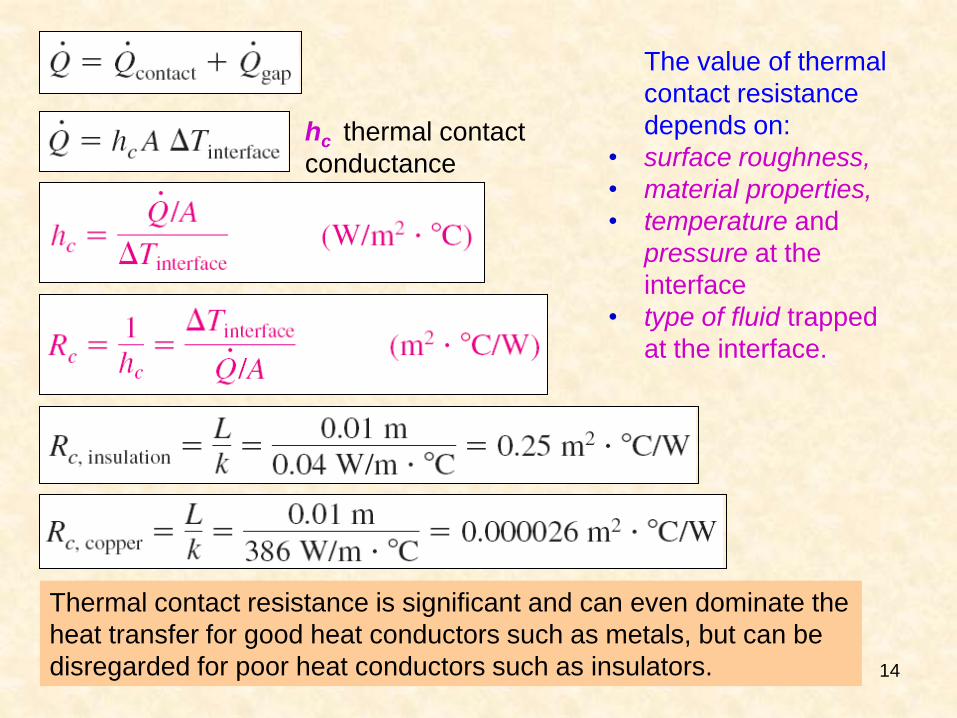
hc thermal contact
conductance
The value of thermal
contact resistance
depends on:
• surface roughness,
• material properties,
• temperature and
pressure at the
interface
• type of fluid trapped
at the interface.
Thermal contact resistance is significant and can even dominate the
heat transfer for good heat conductors such as metals, but can be
disregarded for poor heat conductors such as insulators.
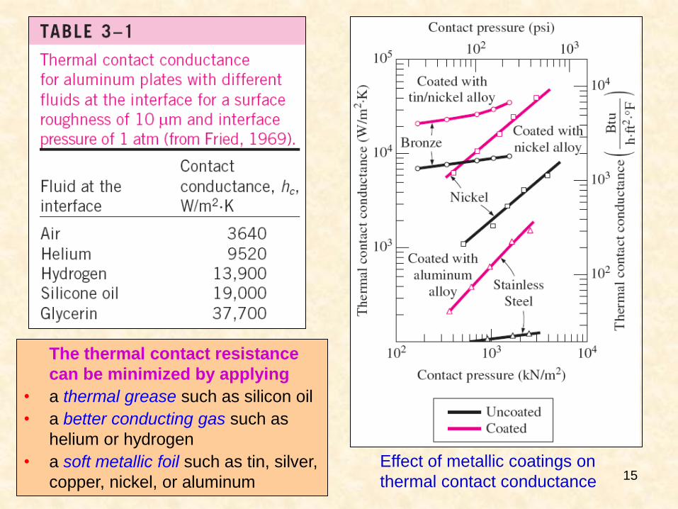
15 Effect of metallic coatings on
thermal contact conductance
The thermal contact resistance
can be minimized by applying
• a thermal grease such as silicon oil
• a better conducting gas such as
helium or hydrogen
• a soft metallic foil such as tin, silver,
copper, nickel, or aluminum
16
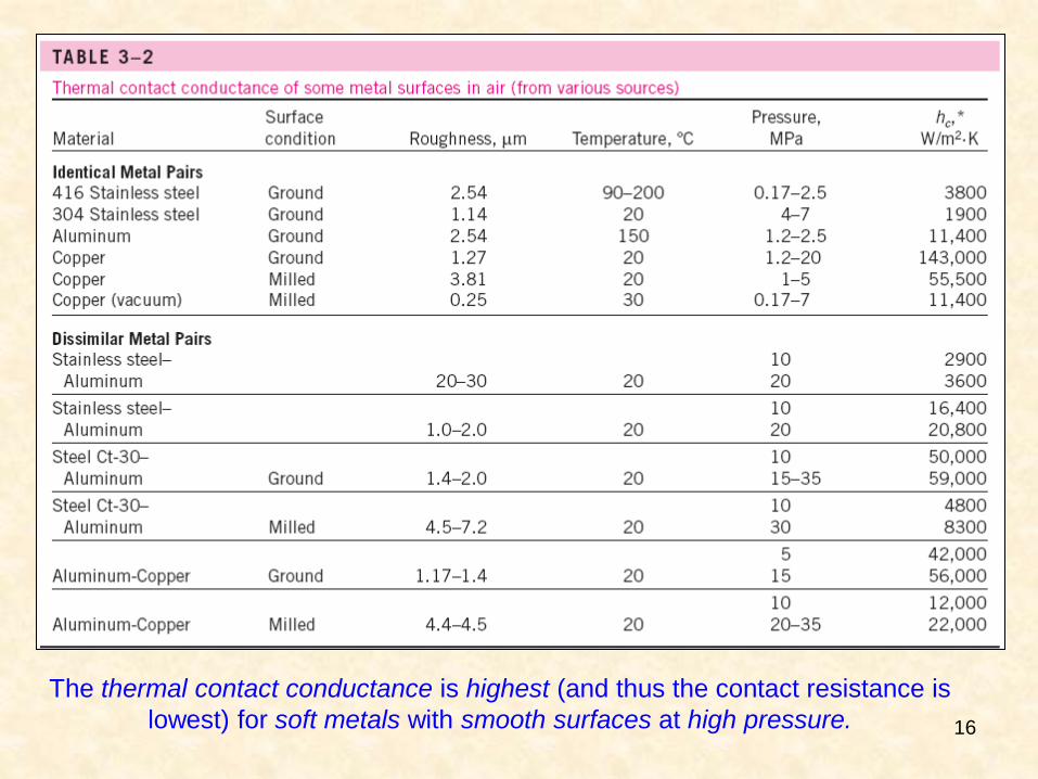
The thermal contact conductance is highest (and thus the contact resistance is
lowest) for soft metals with smooth surfaces at high pressure.
17
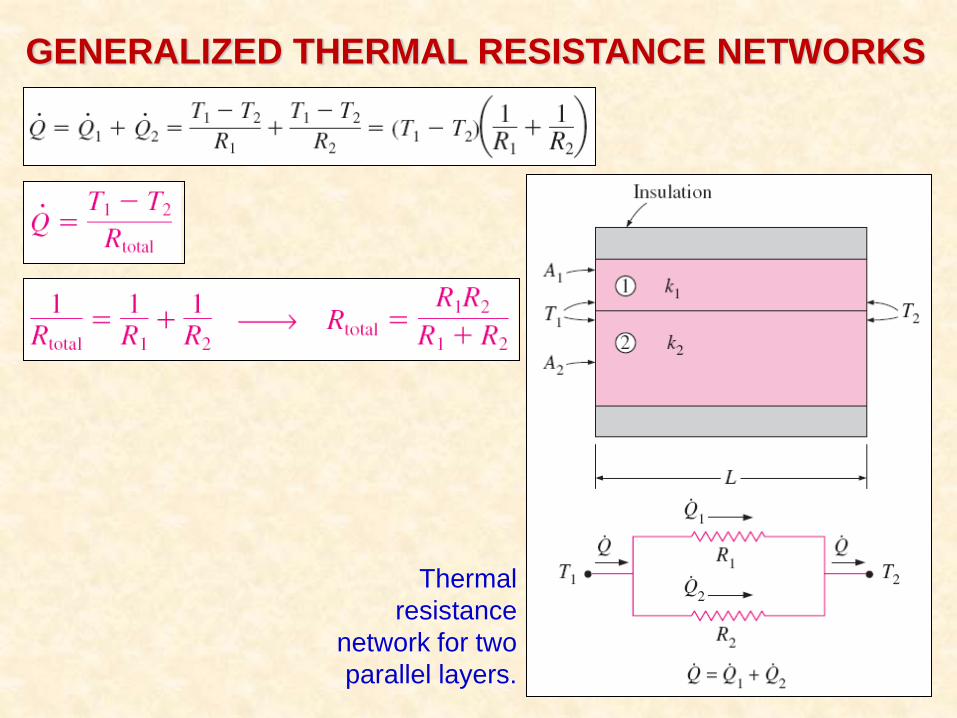
GENERALIZED THERMAL RESISTANCE NETWORKS
Thermal
resistance
network for two
parallel layers.
18
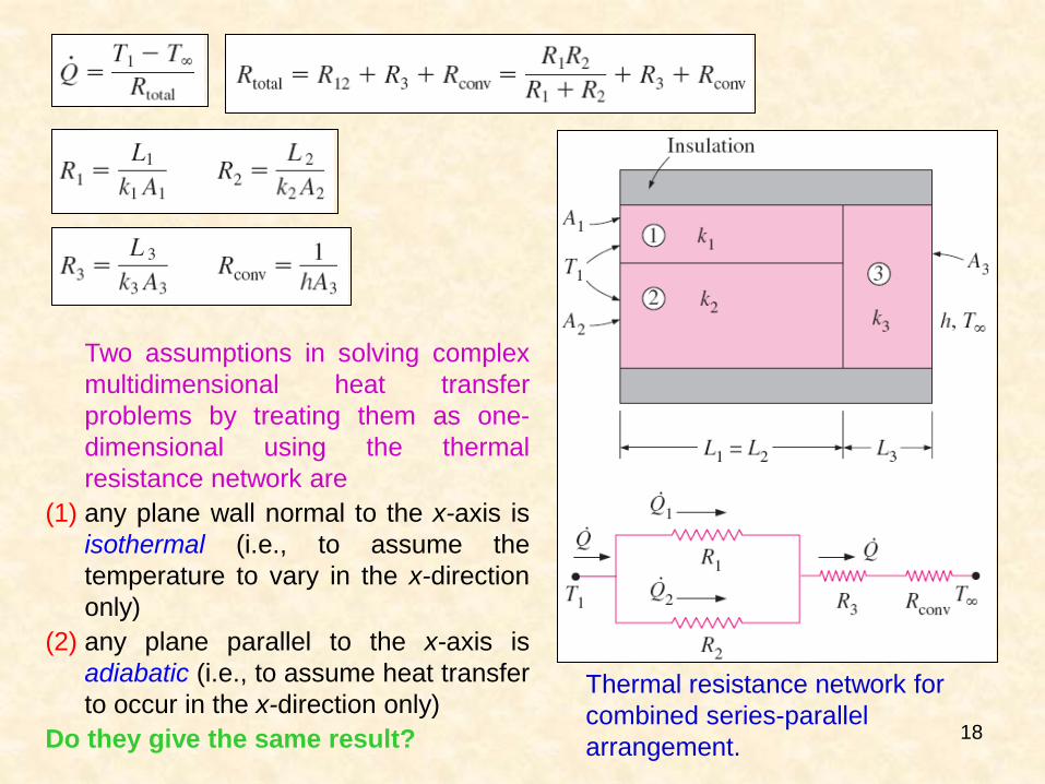
Thermal resistance network for
combined series-parallel
arrangement.
Two assumptions in solving complex
multidimensional heat transfer
problems by treating them as one-
dimensional using the thermal
resistance network are
(1) any plane wall normal to the x-axis is
isothermal (i.e., to assume the
temperature to vary in the x-direction
only)
(2) any plane parallel to the x-axis is
adiabatic (i.e., to assume heat transfer
to occur in the x-direction only)
Do they give the same result?
19
HEAT CONDUCTION IN CYLINDERS AND SPHERES
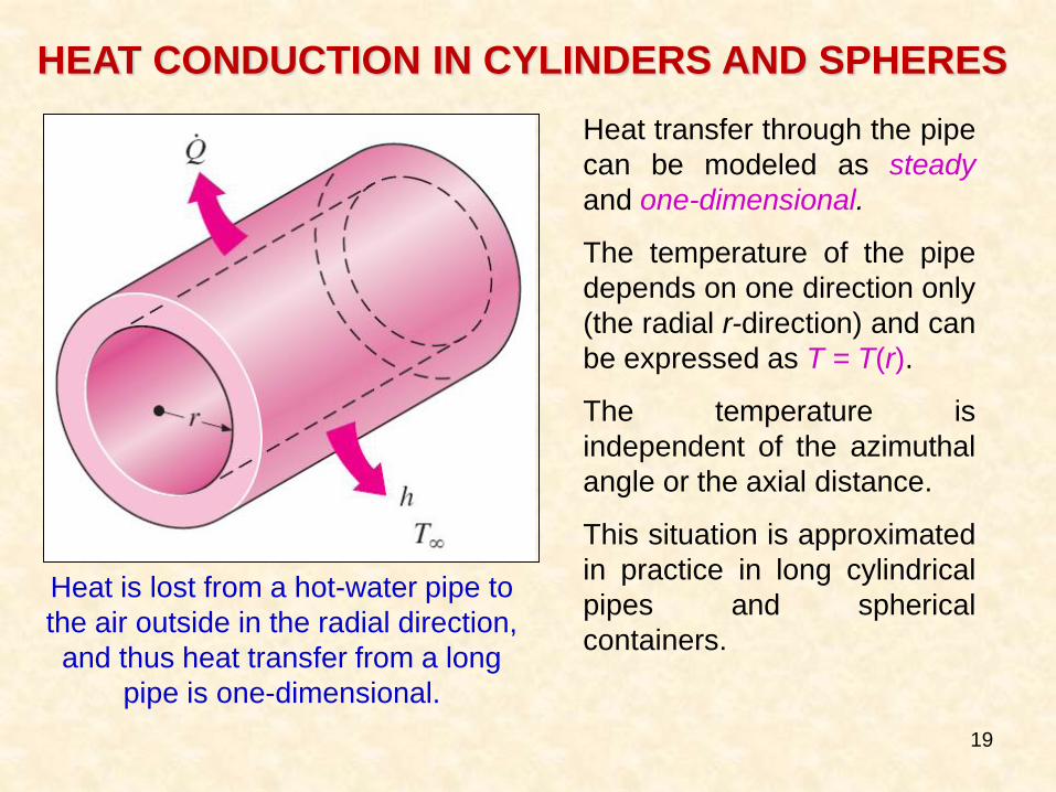
Heat is lost from a hot-water pipe to
the air outside in the radial direction,
and thus heat transfer from a long
pipe is one-dimensional.
Heat transfer through the pipe
can be modeled as steady
and one-dimensional.
The temperature of the pipe
depends on one direction only
(the radial r-direction) and can
be expressed as T = T(r).
The temperature is
independent of the azimuthal
angle or the axial distance.
This situation is approximated
in practice in long cylindrical
pipes and spherical
containers.
20
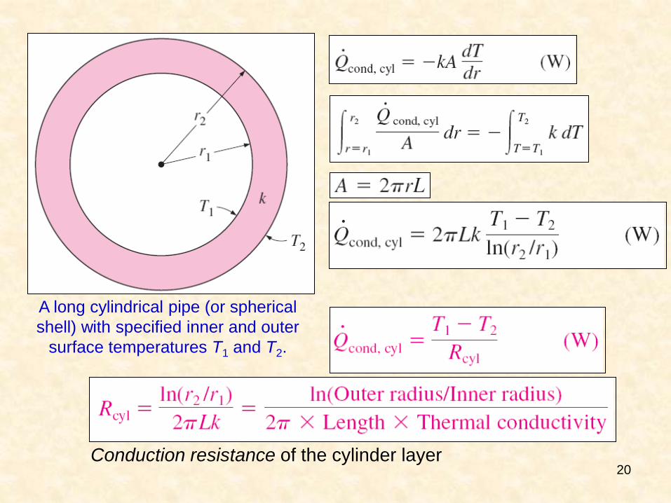
A long cylindrical pipe (or spherical
shell) with specified inner and outer
surface temperatures T1 and T2.
Conduction resistance of the cylinder layer
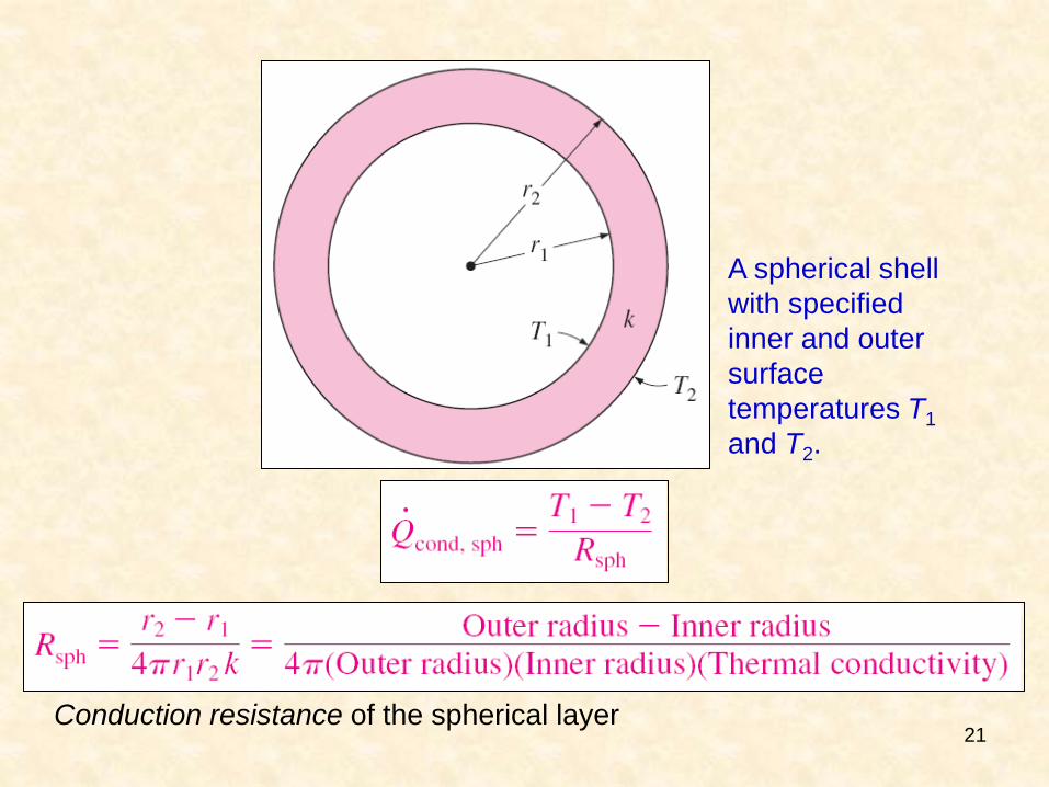
21 Conduction resistance of the spherical layer
A spherical shell
with specified
inner and outer
surface
temperatures T1
and T2.
22
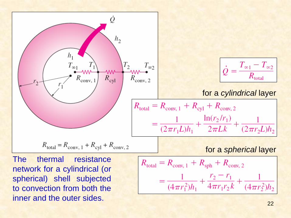
The thermal resistance
network for a cylindrical (or
spherical) shell subjected
to convection from both the
inner and the outer sides.
for a cylindrical layer
for a spherical layer
23
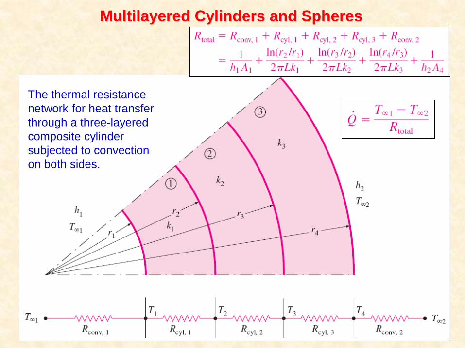
Multilayered Cylinders and Spheres
The thermal resistance
network for heat transfer
through a three-layered
composite cylinder
subjected to convection
on both sides.
24
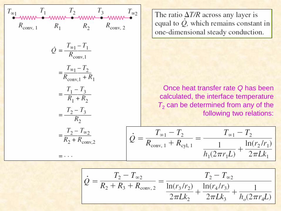
Once heat transfer rate Q has been
calculated, the interface temperature
T2 can be determined from any of the
following two relations:
25
CRITICAL RADIUS OF INSULATION
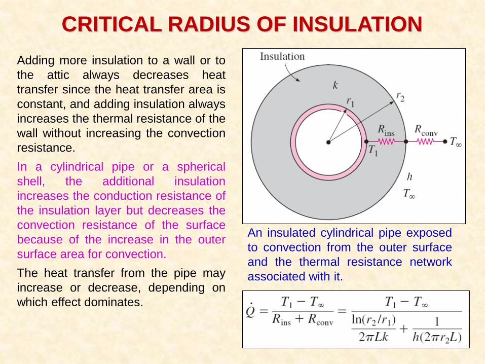
Adding more insulation to a wall or to
the attic always decreases heat
transfer since the heat transfer area is
constant, and adding insulation always
increases the thermal resistance of the
wall without increasing the convection
resistance.
In a cylindrical pipe or a spherical
shell, the additional insulation
increases the conduction resistance of
the insulation layer but decreases the
convection resistance of the surface
because of the increase in the outer
surface area for convection.
The heat transfer from the pipe may
increase or decrease, depending on
which effect dominates.
An insulated cylindrical pipe exposed
to convection from the outer surface
and the thermal resistance network
associated with it.
26
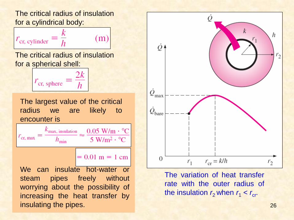
The critical radius of insulation
for a cylindrical body:
The critical radius of insulation
for a spherical shell:
The variation of heat transfer
rate with the outer radius of
the insulation r2 when r1 < rcr.
We can insulate hot-water or
steam pipes freely without
worrying about the possibility of
increasing the heat transfer by
insulating the pipes.
The largest value of the critical
radius we are likely to
encounter is
27
HEAT TRANSFER FROM FINNED SURFACES
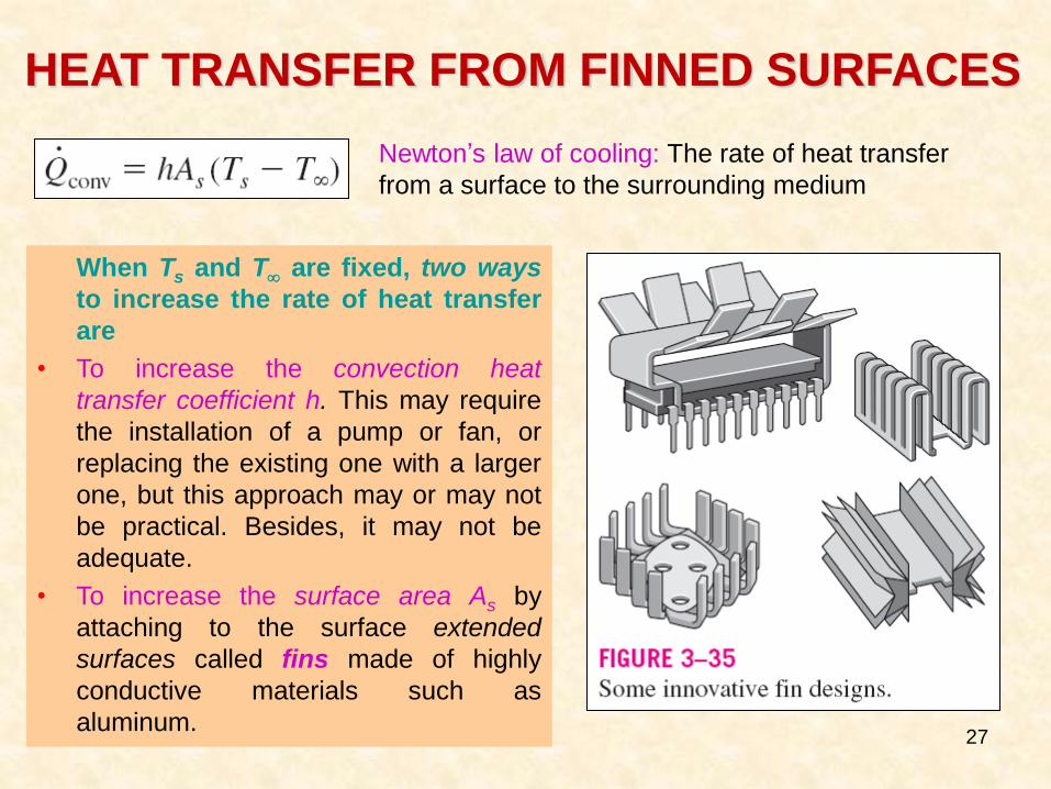
When Ts and T are fixed, two ways
to increase the rate of heat transfer
are
• To increase the convection heat
transfer coefficient h. This may require
the installation of a pump or fan, or
replacing the existing one with a larger
one, but this approach may or may not
be practical. Besides, it may not be
adequate.
• To increase the surface area As by
attaching to the surface extended
surfaces called fins made of highly
conductive materials such as
aluminum.
Newton’s law of cooling: The rate of heat transfer
from a surface to the surrounding medium
28
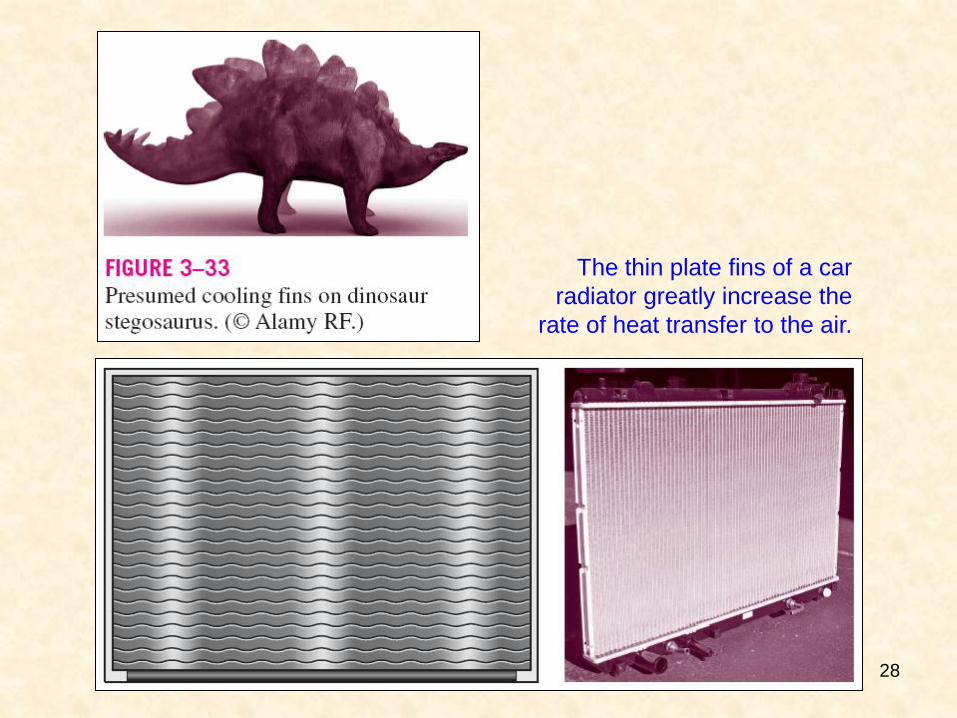
The thin plate fins of a car
radiator greatly increase the
rate of heat transfer to the air.
29
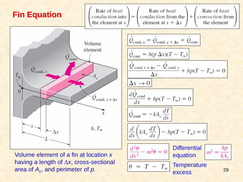
Fin Equation
Volume element of a fin at location x
having a length of x, cross-sectional
area of Ac, and perimeter of p.
Differential
equation
Temperature
excess
30
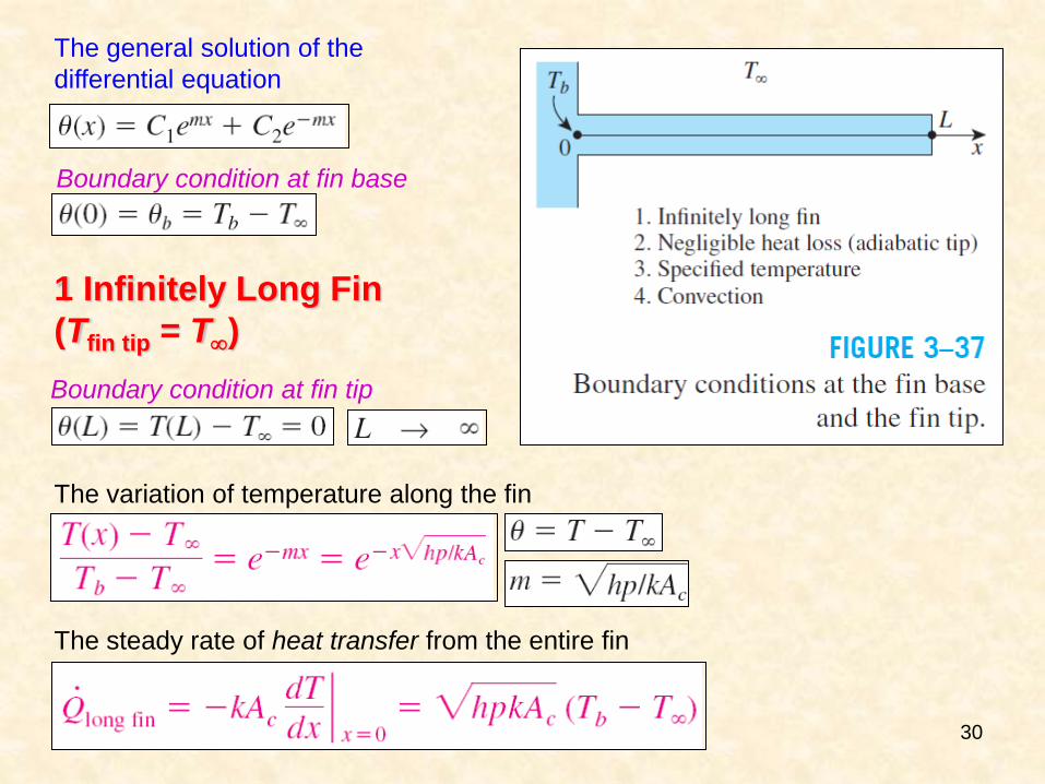
The general solution of the
differential equation
Boundary condition at fin base
1 Infinitely Long Fin
(Tfin tip = T)
Boundary condition at fin tip
The variation of temperature along the fin
The steady rate of heat transfer from the entire fin
31
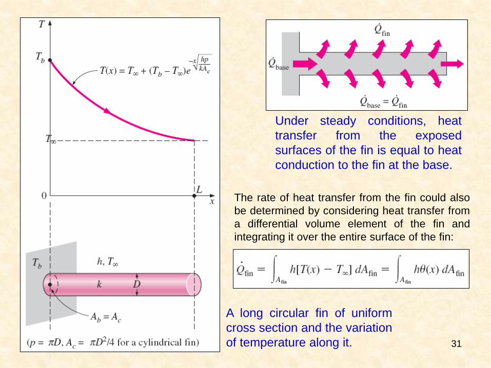
A long circular fin of uniform
cross section and the variation
of temperature along it.
Under steady conditions, heat
transfer from the exposed
surfaces of the fin is equal to heat
conduction to the fin at the base.
The rate of heat transfer from the fin could also
be determined by considering heat transfer from
a differential volume element of the fin and
integrating it over the entire surface of the fin:
32
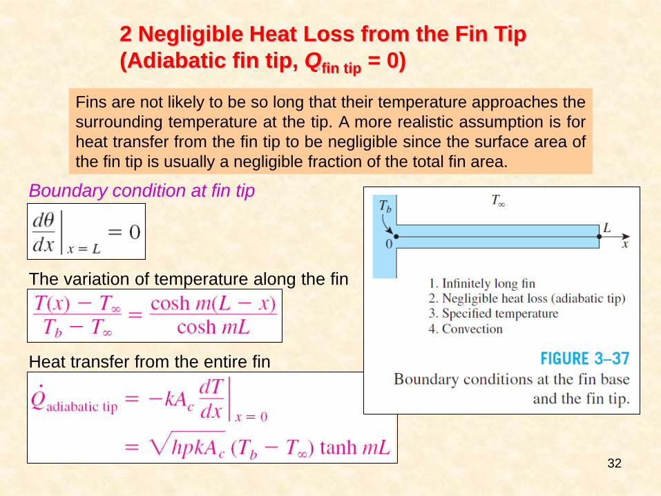
2 Negligible Heat Loss from the Fin Tip
(Adiabatic fin tip, Qfin tip = 0)
Boundary condition at fin tip
The variation of temperature along the fin
Heat transfer from the entire fin
Fins are not likely to be so long that their temperature approaches the
surrounding temperature at the tip. A more realistic assumption is for
heat transfer from the fin tip to be negligible since the surface area of
the fin tip is usually a negligible fraction of the total fin area.
33
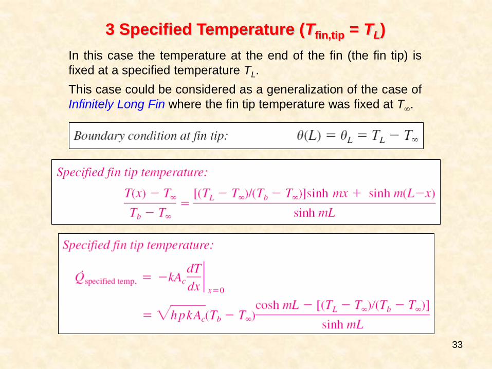
3 Specified Temperature (Tfin,tip = TL)
In this case the temperature at the end of the fin (the fin tip) is
fixed at a specified temperature TL.
This case could be considered as a generalization of the case of
Infinitely Long Fin where the fin tip temperature was fixed at T.
34
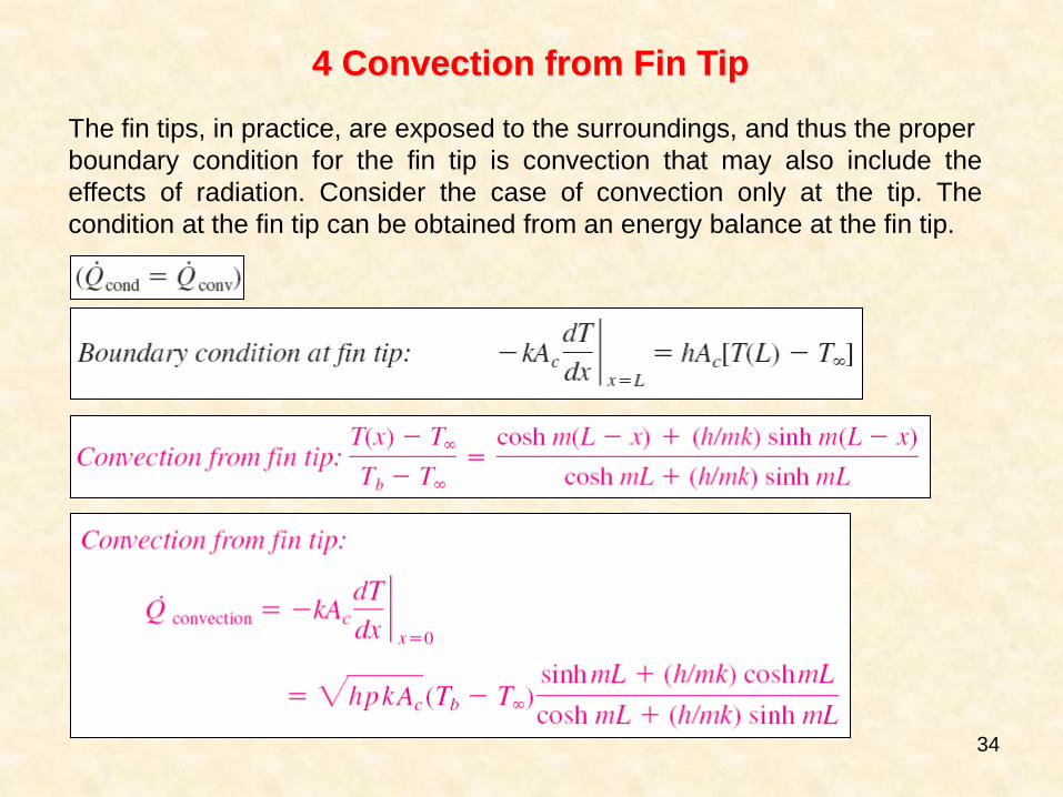
4 Convection from Fin Tip
The fin tips, in practice, are exposed to the surroundings, and thus the proper
boundary condition for the fin tip is convection that may also include the
effects of radiation. Consider the case of convection only at the tip. The
condition at the fin tip can be obtained from an energy balance at the fin tip.
35
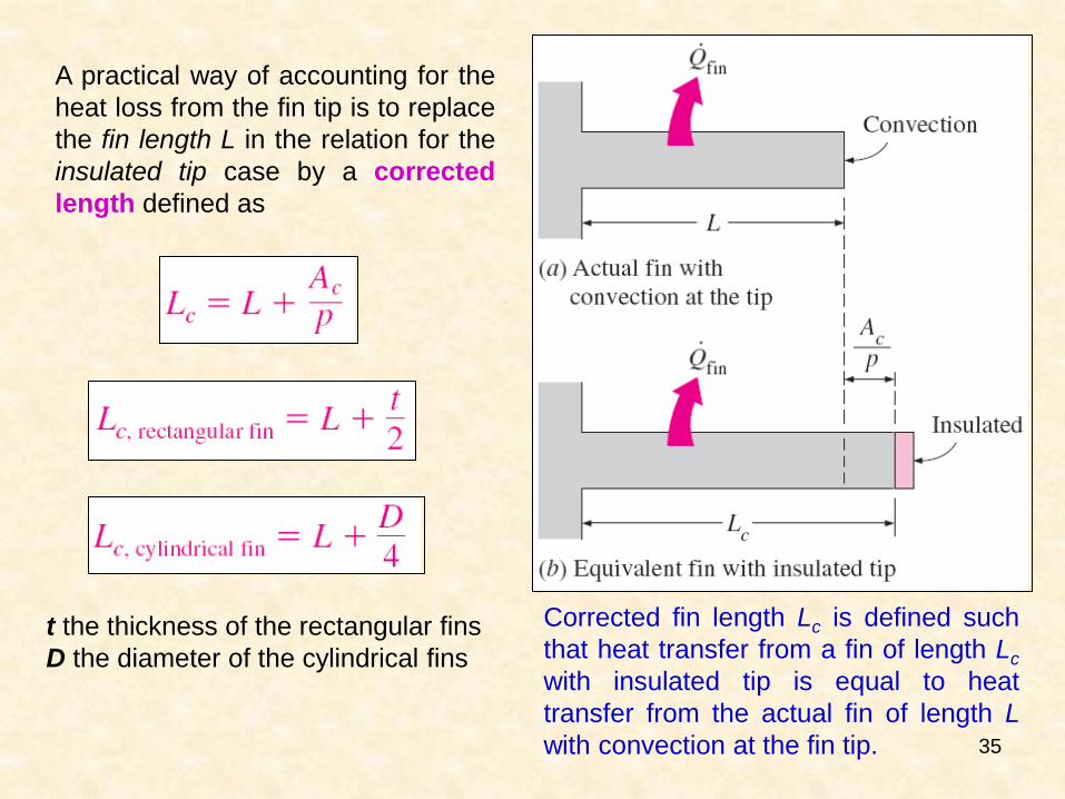
A practical way of accounting for the
heat loss from the fin tip is to replace
the fin length L in the relation for the
insulated tip case by a corrected
length defined as
Corrected fin length Lc is defined such
that heat transfer from a fin of length Lc
with insulated tip is equal to heat
transfer from the actual fin of length L
with convection at the fin tip.
t the thickness of the rectangular fins
D the diameter of the cylindrical fins
36
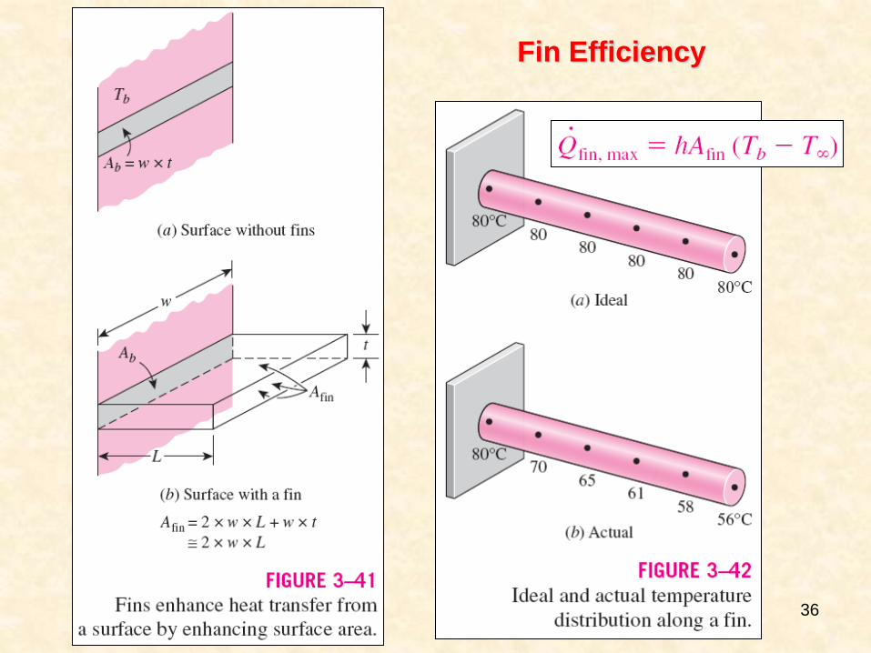
Fin Efficiency
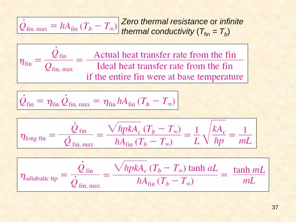
37
Zero thermal resistance or infinite
thermal conductivity (Tfin = Tb)
38
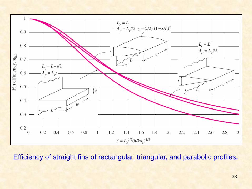
Efficiency of straight fins of rectangular, triangular, and parabolic profiles.
39
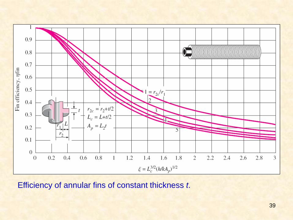
Efficiency of annular fins of constant thickness t.
40
41
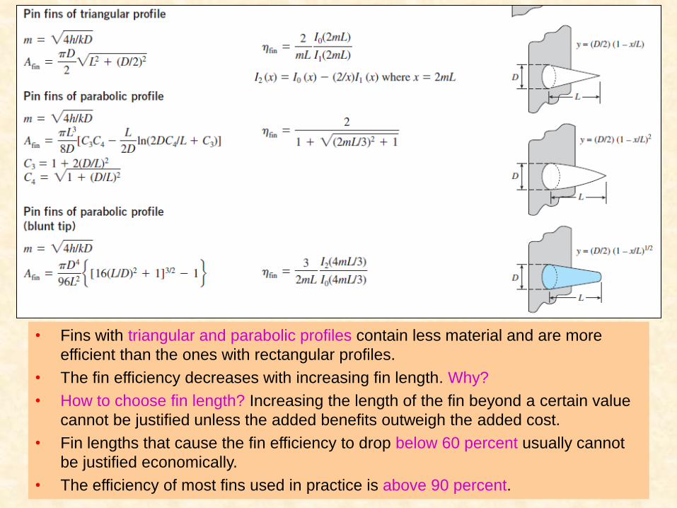
• Fins with triangular and parabolic profiles contain less material and are more
efficient than the ones with rectangular profiles.
• The fin efficiency decreases with increasing fin length. Why?
• How to choose fin length? Increasing the length of the fin beyond a certain value
cannot be justified unless the added benefits outweigh the added cost.
• Fin lengths that cause the fin efficiency to drop below 60 percent usually cannot
be justified economically.
• The efficiency of most fins used in practice is above 90 percent.
42
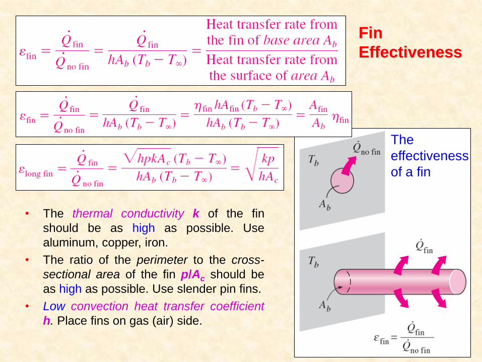
Fin
Effectiveness
The
effectiveness
of a fin
• The thermal conductivity k of the fin
should be as high as possible. Use
aluminum, copper, iron.
• The ratio of the perimeter to the cross-
sectional area of the fin p/Ac should be
as high as possible. Use slender pin fins.
• Low convection heat transfer coefficient
h. Place fins on gas (air) side.
43
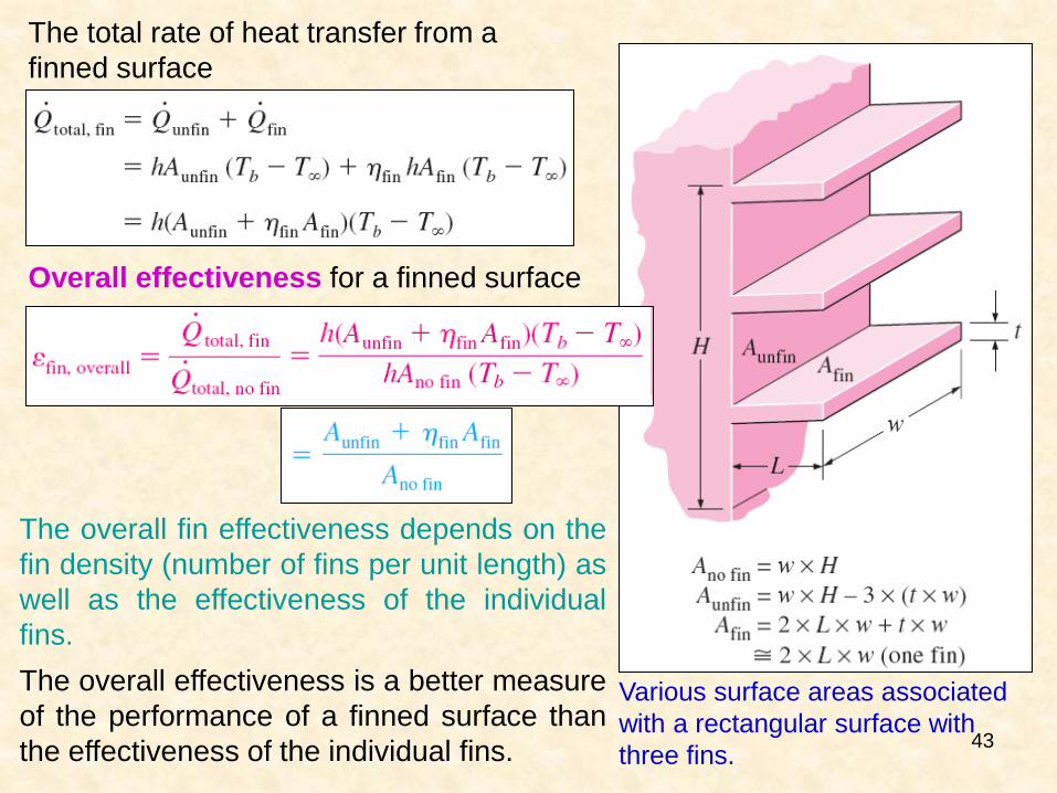
Various surface areas associated
with a rectangular surface with
three fins.
Overall effectiveness for a finned surface
The overall fin effectiveness depends on the
fin density (number of fins per unit length) as
well as the effectiveness of the individual
fins.
The overall effectiveness is a better measure
of the performance of a finned surface than
the effectiveness of the individual fins.
The total rate of heat transfer from a
finned surface
44
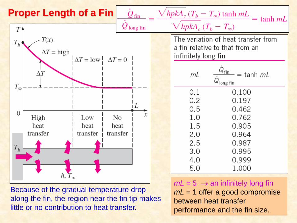
Proper Length of a Fin
Because of the gradual temperature drop
along the fin, the region near the fin tip makes
little or no contribution to heat transfer.
mL = 5 an infinitely long fin
mL = 1 offer a good compromise
between heat transfer
performance and the fin size.
45
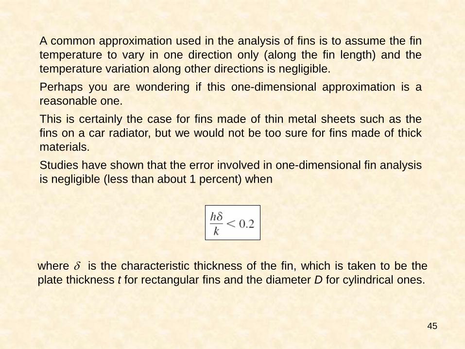
A common approximation used in the analysis of fins is to assume the fin
temperature to vary in one direction only (along the fin length) and the
temperature variation along other directions is negligible.
Perhaps you are wondering if this one-dimensional approximation is a
reasonable one.
This is certainly the case for fins made of thin metal sheets such as the
fins on a car radiator, but we would not be too sure for fins made of thick
materials.
Studies have shown that the error involved in one-dimensional fin analysis
is negligible (less than about 1 percent) when
where is the characteristic thickness of the fin, which is taken to be the
plate thickness t for rectangular fins and the diameter D for cylindrical ones.
46
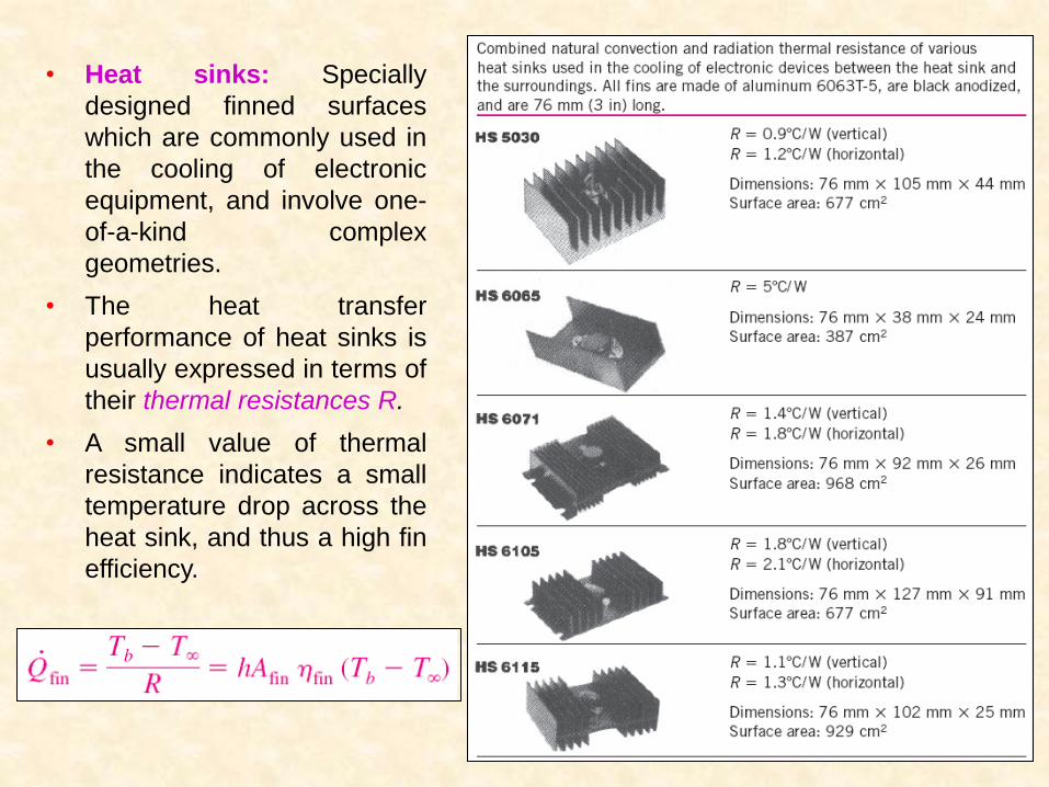
• Heat sinks: Specially
designed finned surfaces
which are commonly used in
the cooling of electronic
equipment, and involve one-
of-a-kind complex
geometries.
• The heat transfer
performance of heat sinks is
usually expressed in terms of
their thermal resistances R.
• A small value of thermal
resistance indicates a small
temperature drop across the
heat sink, and thus a high fin
efficiency.
47
BIOHEAT TRANSFER EQUATION
The study of heat transfer in biological systems is referred to as
bioheat transfer. It is the study of heat transfer within the human
body or external to the body.
Bioheat transfer can be considered as a subfield of biomedical
engineering with its foundation in the heat transfer engineering.
Heat transfer within the human body, in particular in adverse
environments, is an active area of research for the development
of new medical treatments or devices to minimize the effects of
the adverse conditions.
The transport of thermal energy in living tissues is a very
complex process. It involves a multiple of mechanisms such as
conduction, convection, radiation, evaporation, phase change,
metabolic heat generation (heat generated by the body through
the digestion of food, work and exercise), and perfusion
(exchange of thermal energy between flowing blood and the
surrounding tissue).
48
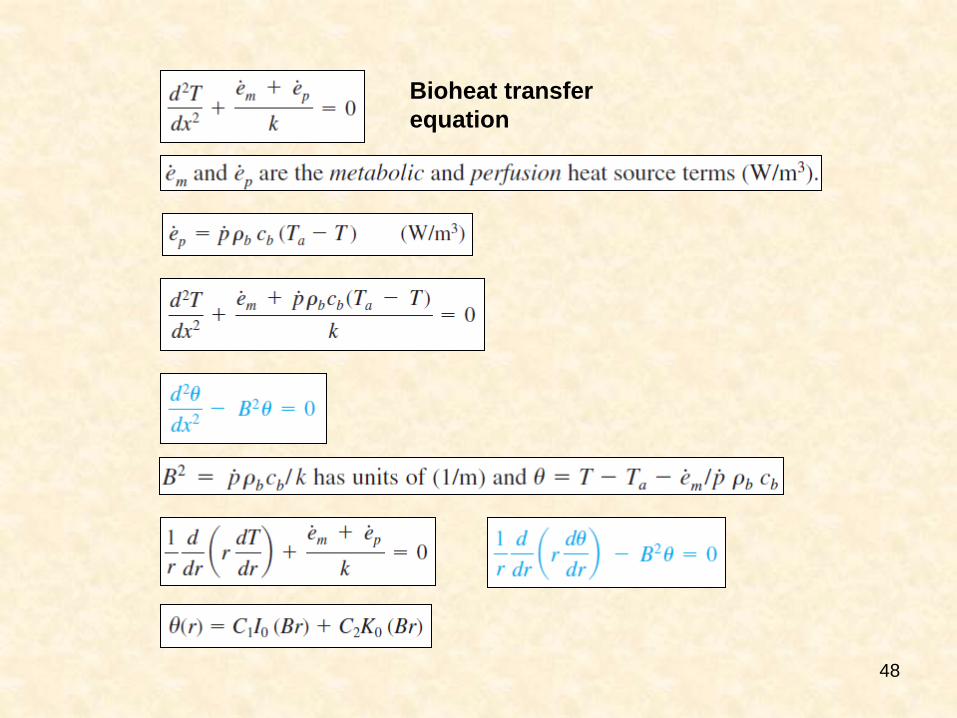
Bioheat transfer
equation
49
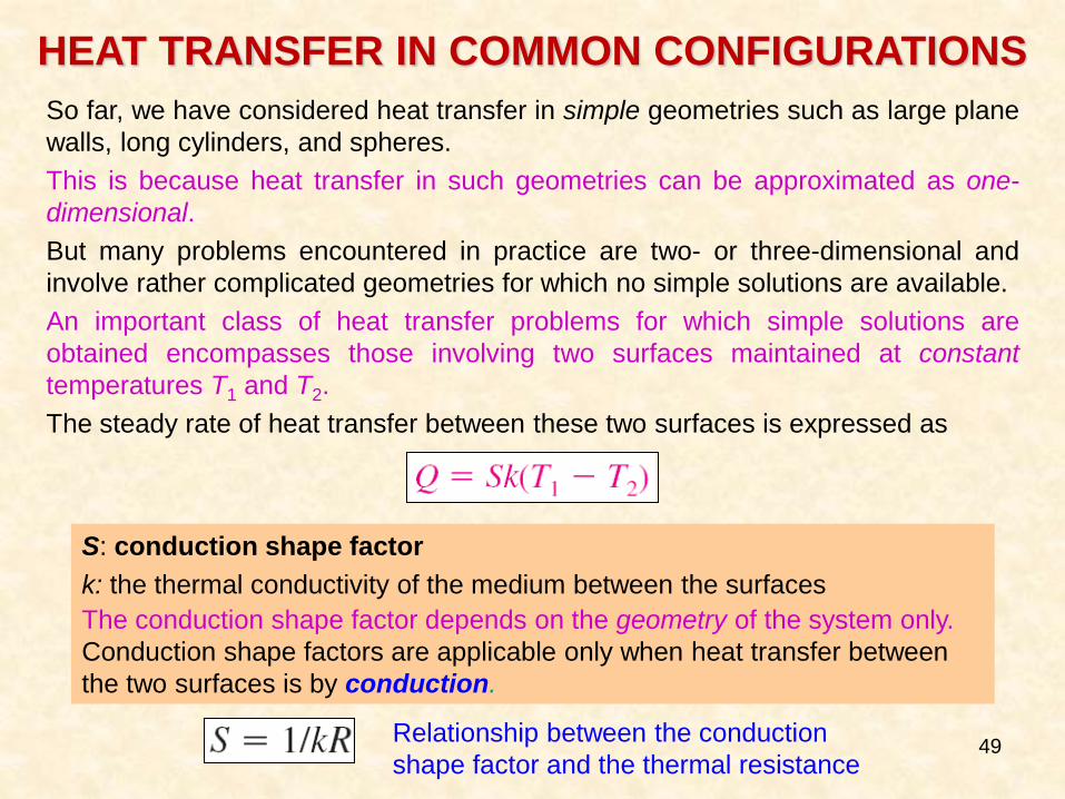
HEAT TRANSFER IN COMMON CONFIGURATIONS
So far, we have considered heat transfer in simple geometries such as large plane
walls, long cylinders, and spheres.
This is because heat transfer in such geometries can be approximated as one-
dimensional.
But many problems encountered in practice are two- or three-dimensional and
involve rather complicated geometries for which no simple solutions are available.
An important class of heat transfer problems for which simple solutions are
obtained encompasses those involving two surfaces maintained at constant
temperatures T1 and T2.
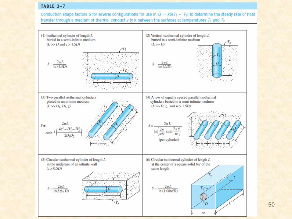
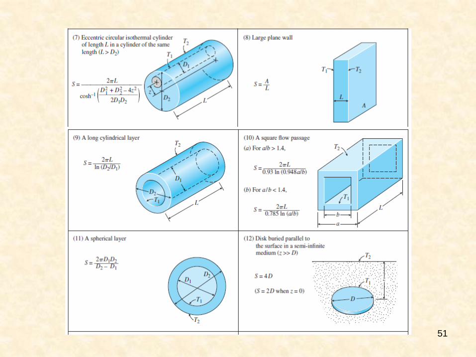
The steady rate of heat transfer between these two surfaces is expressed as
S: conduction shape factor
k: the thermal conductivity of the medium between the surfaces
The conduction shape factor depends on the geometry of the system only.
Conduction shape factors are applicable only when heat transfer between
the two surfaces is by conduction.
Relationship between the conduction
shape factor and the thermal resistance
50
51
52
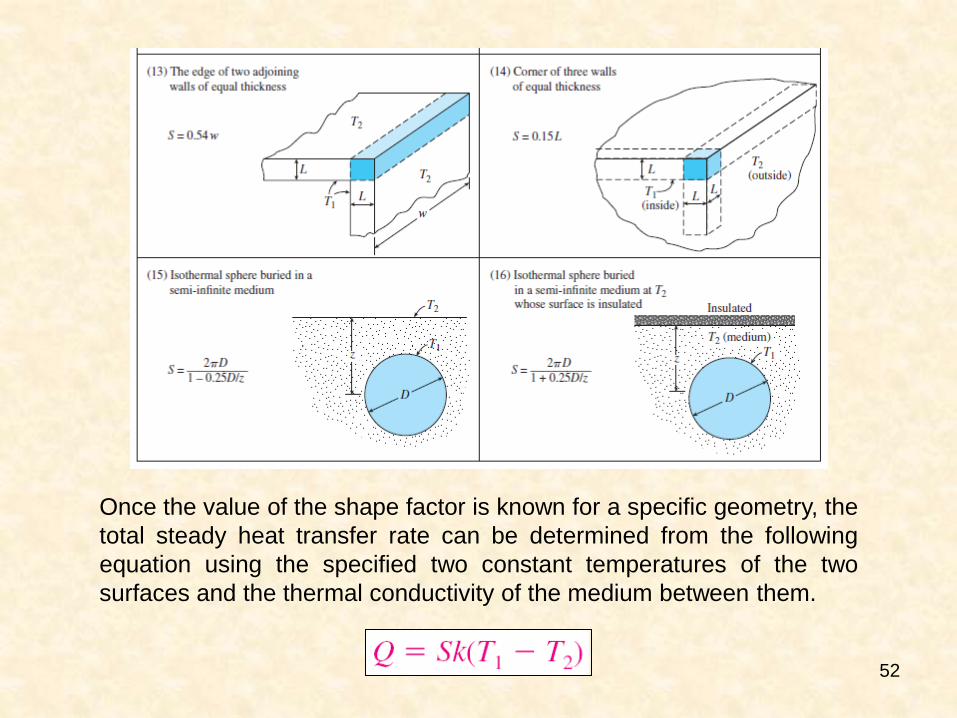
Once the value of the shape factor is known for a specific geometry, the
total steady heat transfer rate can be determined from the following
equation using the specified two constant temperatures of the two
surfaces and the thermal conductivity of the medium between them.
53
Summary
• Steady Heat Conduction in Plane Walls
Thermal Resistance Concept
Thermal Resistance Network
Multilayer Plane Walls
• Thermal Contact Resistance
• Generalized Thermal Resistance Networks
• Heat Conduction in Cylinders and Spheres
Multilayered Cylinders and Spheres
• Critical Radius of Insulation
• Heat Transfer from Finned Surfaces
Fin Equation
Fin Efficiency
Fin Effectiveness
Proper Length of a Fin
• Bioheat Transfer Equation
• Heat Transfer in Common Configurations