Embed Size (px)
Citation preview
83
CHAPTER 3
MATERIAL CHARACTERISTICS WORK AND
TESTING PROCEDURES
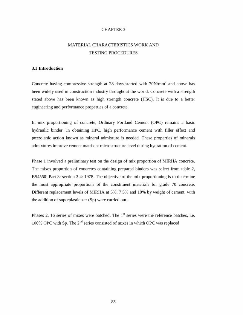
3.1 Introduction
Concrete having compressive strength at 28 days started with 70N/mm2 and above has
been widely used in construction industry throughout the world. Concrete with a strength
stated above has been known as high strength concrete (HSC). It is due to a better
engineering and performance properties of a concrete.
In mix proportioning of concrete, Ordinary Portland Cement (OPC) remains a basic
hydraulic binder. In obtaining HPC, high performance cement with filler effect and
pozzolanic action known as mineral admixture is needed. These properties of minerals
admixtures improve cement matrix at microstructure level during hydration of cement.
Phase 1 involved a preliminary test on the design of mix proportion of MIRHA concrete.
The mixes proportion of concretes containing prepared binders was select from table 2,
BS4550: Part 3: section 3.4: 1978. The objective of the mix proportioning is to determine
the most appropriate proportions of the constituent materials for grade 70 concrete.
Different replacement levels of MIRHA at 5%, 7.5% and 10% by weight of cement, with
the addition of superplasticizer (Sp) were carried out.
Phases 2, 16 series of mixes were batched. The 1st series were the reference batches, i.e.
100% OPC with Sp. The 2nd series consisted of mixes in which OPC was replaced
84
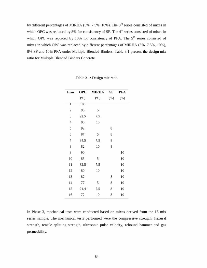
by different percentages of MIRHA (5%, 7.5%, 10%). The 3rd series consisted of mixes in
which OPC was replaced by 8% for consistency of SF. The 4th series consisted of mixes in
which OPC was replaced by 10% for consistency of PFA. The 5th series consisted of
mixes in which OPC was replaced by different percentages of MIRHA (5%, 7.5%, 10%),
8% SF and 10% PFA under Multiple Blended Binders. Table 3.1 present the design mix
ratio for Multiple Blended Binders Concrete
Table 3.1: Design mix ratio
In Phase 3, mechanical tests were conducted based on mixes derived from the 16 mix
series sample. The mechanical tests performed were the compressive strength, flexural
strength, tensile splitting strength, ultrasonic pulse velocity, rebound hammer and gas
permeability.
Item
OPC (%)
MIRHA (%)
SF (%)
PFA (%)
1 100
2 95 5
3 92.5 7.5
4 90 10
5 92
8
6 87 5 8
7 84.5 7.5 8
8 82 10 8
9 90
10
10 85 5
10
11 82.5 7.5
10
12 80 10
10
13 82
8 10
14 77 5 8 10
15 74.4 7.5 8 10
16 72 10 8 10
85
3.2 Materials Used
The constituent materials used in the laboratory used Portland cement (Ordinary Portland
Cement BSEN 197-1-2000), crushed aggregate with maximum size of 20mm according
to BS 812-103.2 1989, natural sand, with 100 % passing 425 mm sieved (BS EN
12620:2002), microwave incinerator rice husk ash (MIRHA) with high reactive silica
content, free water (BS 3148: 1980), superplasticizer (BS 5075-3:1985 and ASTM C494/C
494M-2004), silica fume (SF) and pulverized fuel ash (PFA).
3.2.1 Ordinary Portland Cement (OPC)
The type of cement used was the Ordinary Portland Cement (OPC) branded 'Cap Rumah'
supplied by the Lafarge Malayan Cement (Ordinary Portland Cement BSEN 197-1-2000)
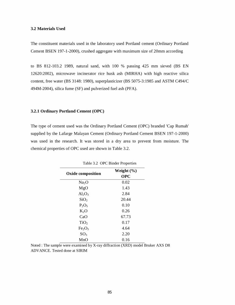
was used in the research. It was stored in a dry area to prevent from moisture. The
chemical properties of OPC used are shown in Table 3.2.
Table 3.2 OPC Binder Properties
Oxide composition Weight (%) OPC
Na2O 0.02 MgO 1.43 Al2O3 2.84 SiO2 20.44 P2O5 0.10 K2O 0.26 CaO 67.73 TiO2 0.17 Fe2O3 4.64 SO3 2.20
MnO 0.16 Noted : The sample were examined by X-ray diffraction (XRD) model Bruker AXS D8 ADVANCE. Tested done at SIRIM
86
3.2.2 Microwave Incinerator
The rice husks are residue produced during the defusing operation of paddy rice, and
microwave incinerator rice husk ash is the ash produced from the burning of rice husk.
The rice husk used in the present investigation was obtained from a rice mill in Changkat
Lada, Perak, Malaysia.
Microwave incinerator of materials offers a number of advantages over conventional
incinerator methods. Microwave energy can penetrate the material, achieving rapid
internal incinerator which may also improve the structural properties of the product. Along
with the possibility of a more controlled incinerator, this results in an efficient process that
has the potential to reduce the requirements on time and energy. Microwave incinerator
heated produce sintering, drying and joining.
3.2.2.1 Benefits of Microwave Incinerator
There is a fundamental difference in the nature of microwave incinerator when compared
to conventional methods of incinerator materials. Conventional incinerator relies on one or
more of the heat transfer mechanisms of convection, conduction, or radiation to transfer
thermal energy into the materials. In all three cases, the energy is deposited at the surface
of the material and the resulting temperature gradient established in the material causes the
transfer of heat into the core of the object.
Thus, the temperature gradient is always into the material with the highest temperatures
being at the surface. In microwave incinerator, the microwave energy not only interacts
with the surface material, but also penetrates the surface and interacts with the core of the
material as well. Energy is transferred from the electromagnetic field into thermal energy
throughout the entire volume of the material that is penetrated by the radiation.
87
Microwave incinerator does not rely on conduction from the surface to bring heat into
thecore region. Since the incinerator rate is not limited by conduction through the surface
layer, the material can be heated more quickly. Another important aspect of microwave
incinerator is that it results in a temperature gradient in the reverse direction compared to
conventional incinerator, that is to say, the highest temperatures occur at the centre of the
object and heat is conducted to the outer layers of the material.
For operations such as material drying, this effect is highly beneficial. In addition to the
reversal of the temperature gradient, the gradient is smaller compared to conventional
incinerator because the heat is generated from all parts of the materials that are receiving
the radiation. This effect reduces the internal stresses in the material and can help
eliminate problems such as cracking that may occur when the internal stresses become too
large. In some cases, the difference in product quality between the two incinerator
methods is sufficient to justify the use of microwave incinerator. In other cases, the
smaller equipment used in microwave incinerator devices may be essential to fitting a new
device within the limited existing space in a factory. In most instances where microwave
incinerator is economically justifiable, the shorter process time afforded by the volumetric
incinerator aspect tips the scales in favor of microwave incinerator. The bottom line is that
microwave incinerator has more potential than is economically affordable in some
instances.
3.2.2.2 Microwave Incinerator Application
Drying of materials involves the mechanisms of heat and mass transport. Heat must be
delivered into the material as a means to drive moisture from the material. Incinerating the
material causes an increase in the saturation vapur pressure within the material, so that it is
higher at the surface than the partial pressure of the surrounding air. The resulting pressure
gradient drives moisture from the material by means of evaporation. The drying
88
rate of a material is limited by the rate at which capillary suction draws moisture to the
surface from within the material. When using conventional incinerator methods, the
temperature gradient and moisture gradient in the material occur in opposite directions
because the material is heated externally. This can result in excessive drying of the surface
layers, or "crusting". This in turn inhibits the transfer of heat into the material and the
transport of moisture to the surface. Both of these effects are detrimental to the drying rate.
Using microwave incinerator, both the temperature and moisture gradients occur in the
same direction. This effect minimizes the likelihood of crusting and optimizes the rate
f moisture removal from the material. Increasing the drying rate with the use of
microwaves allows for the use of smaller drying units in industrial processes.
Companies employing the use of microwaves in the printing industry report a 30% cost
savings compared to conventional incinerator for the task of drying the ink in printed
materials. An added benefit of this technology in the drying process for certain products,
such as paper, is that the risk of fire is eliminated since the use of open-flame heaters has
been discontinued.
Drying rates are increased while the product temperature only reaches 80° F instead of
200°-300° F as with conventional incinerator. Glued products can be dried much more
quickly, and leather products can be dried in 30%-50% less time after tanning and with
less shrinkage using microwaves. Due to the penetrating effects of microwaves, large
poured molds used in the foundry industry can be dried faster and with improved product
quality. In the case of large foundry molds, the low thermal conductivity of the material
and high thermal gradients present in drying creates significant complications such as
cracking, when conventional incinerator methods are employed. In the plastics industry,
where solvents must be removed from the product, microwave incinerator is highly
effective because the solvents are heated more readily than the material. The selective
incinerator of the solvents results in less distortion and damage to the final product.
89
One of the most interesting industrial applications involves the use of microwaves to
generate extreme internal stresses in rock and concrete to "crush" the material for removal
or disposal. One industrial application that results in superior material quality with
microwave incinerator is the sintering of ferrite and ceramic materials. Sintering involves
applying pressure and heat to a mold filled with granular or powdered material to cause
the grains to fuse together into a solid entity.
3.2.2.3 Basics of Microwave
Microwaves are part of the electromagnetic spectrum are located between 300 MHz and
300 GHz. Microwave incinerator is defined as the incinerator of a substance by
electromagnetic energy operating in that frequency range. The term radio frequency is
used for high frequency mainly in the United Kingdom. The infrared region is located
between microwaves and visible light. Only restricted microwave or high frequencies are
freely allowed for incinerator in industrial, scientific, and medical applications, the so-
called ISM frequencies. Of these, only 2450 MHz is commonly used in food processing in
Europe, while 915 MHz dominates in America and 896 MHz in the UK. Higher
frequencies are not in active use.
3.2.2.4 Principle of Paddy Husk Microwave Incinerator (microwave kiln (INC-21))
operation
Bench scale result shows that paddy husk is a good dielectric material and can absorb the
microwave energy more efficiently when it carbonised. This microwave kiln (INC-21)
uses the microwave energy as the only incinerator source to burn the paddy. The kiln
consists of a metallic cavity, a refractory and insulation, waveguide, microwave generator,
mode stirrer and microwave leakage proof feeding and discharging door.
90
The metallic cavity is used to house both the material and the microwave energy, where
both are interacted to generate the heat. After starting the microwave firing, microwave
tends to carbonize the material first volumetrically and then once it is burning temperature
the material start burning and thus the heat of combustion of the paddy husk is just enough
to sustain the temperature inside the cavity. Once the material burned, the microwave
energy will generate heat inside the carbonised material and keep it at the specified
temperature. Only the material is heated by microwave and becomes the source of
incinerator, while the empty part of the chamber together with the lining will be kept at
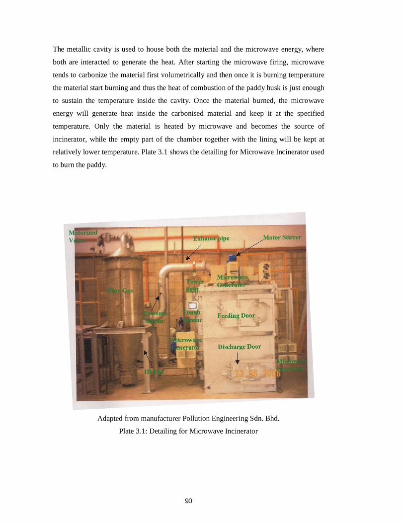
relatively lower temperature. Plate 3.1 shows the detailing for Microwave Incinerator used
to burn the paddy.
Adapted from manufacturer Pollution Engineering Sdn. Bhd.
Plate 3.1: Detailing for Microwave Incinerator
91
3.2.2.5 Combustion of MIRHA
MIRHA was produced from the Rice Husk Carbon (RHC) that was obtained from a rice
mill in Changkat Lada, Perak. The burning of rice husk in a microwave incinerator was
carried out at the concrete laboratory, Department of Civil Engineering, Universiti
Teknologi Petronas, Malaysia. For each incineration, eight gunny sacks (80kg) of rice
husk were used. There is one big door (discharge door) provided underneath the furnace
for ventilation purposes and to start fire. The design of the microwave incinerator was
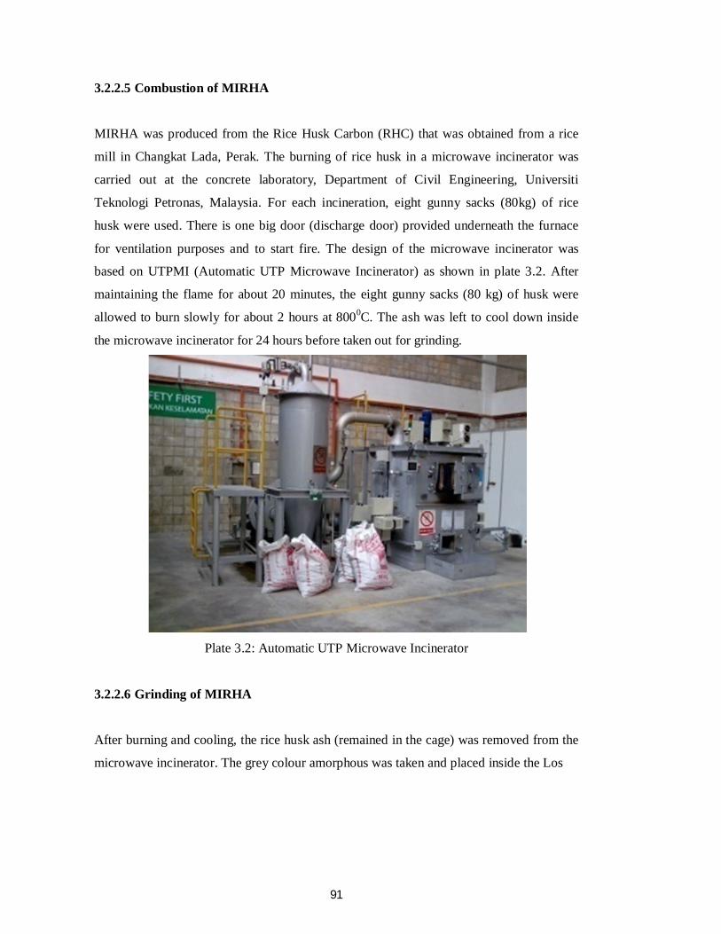
based on UTPMI (Automatic UTP Microwave Incinerator) as shown in plate 3.2. After
maintaining the flame for about 20 minutes, the eight gunny sacks (80 kg) of husk were
allowed to burn slowly for about 2 hours at 8000C. The ash was left to cool down inside
the microwave incinerator for 24 hours before taken out for grinding.
Plate 3.2: Automatic UTP Microwave Incinerator
3.2.2.6 Grinding of MIRHA
After burning and cooling, the rice husk ash (remained in the cage) was removed from the
microwave incinerator. The grey colour amorphous was taken and placed inside the Los
92
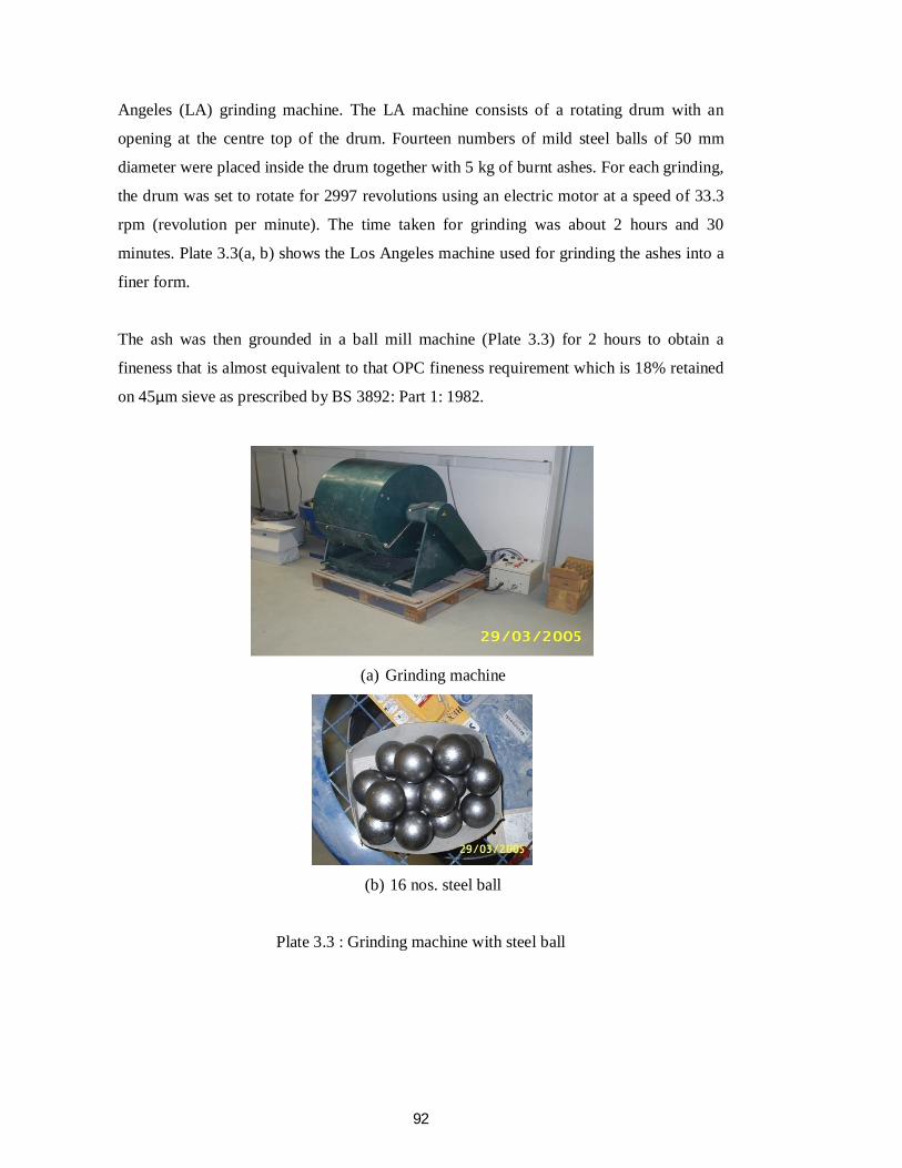
Angeles (LA) grinding machine. The LA machine consists of a rotating drum with an
opening at the centre top of the drum. Fourteen numbers of mild steel balls of 50 mm
diameter were placed inside the drum together with 5 kg of burnt ashes. For each grinding,
the drum was set to rotate for 2997 revolutions using an electric motor at a speed of 33.3
rpm (revolution per minute). The time taken for grinding was about 2 hours and 30
minutes. Plate 3.3(a, b) shows the Los Angeles machine used for grinding the ashes into a
finer form.
The ash was then grounded in a ball mill machine (Plate 3.3) for 2 hours to obtain a
fineness that is almost equivalent to that OPC fineness requirement which is 18% retained
on 45μm sieve as prescribed by BS 3892: Part 1: 1982.
(a) Grinding machine
(b) 16 nos. steel ball
Plate 3.3 : Grinding machine with steel ball
93
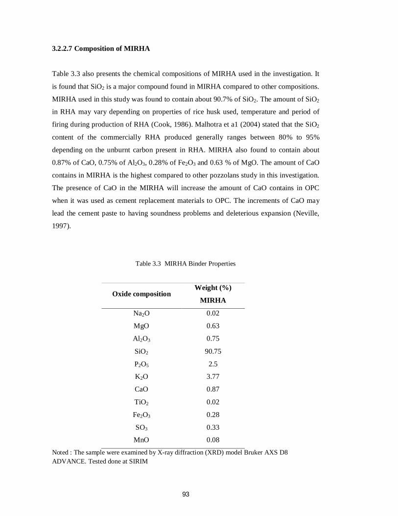
3.2.2.7 Composition of MIRHA
Table 3.3 also presents the chemical compositions of MIRHA used in the investigation. It
is found that SiO2 is a major compound found in MIRHA compared to other compositions.
MIRHA used in this study was found to contain about 90.7% of SiO2. The amount of SiO2
in RHA may vary depending on properties of rice husk used, temperature and period of
firing during production of RHA (Cook, 1986). Malhotra et a1 (2004) stated that the SiO2
content of the commercially RHA produced generally ranges between 80% to 95%
depending on the unburnt carbon present in RHA. MIRHA also found to contain about
0.87% of CaO, 0.75% of Al2O3, 0.28% of Fe2O3 and 0.63 % of MgO. The amount of CaO
contains in MIRHA is the highest compared to other pozzolans study in this investigation.
The presence of CaO in the MIRHA will increase the amount of CaO contains in OPC
when it was used as cement replacement materials to OPC. The increments of CaO may
lead the cement paste to having soundness problems and deleterious expansion (Neville,
1997).
Table 3.3 MIRHA Binder Properties
Oxide composition Weight (%)
MIRHA
Na2O 0.02
MgO 0.63
Al2O3 0.75
SiO2 90.75
P2O5 2.5
K2O 3.77
CaO 0.87
TiO2 0.02
Fe2O3 0.28
SO3 0.33
MnO 0.08
Noted : The sample were examined by X-ray diffraction (XRD) model Bruker AXS D8 ADVANCE. Tested done at SIRIM
94
MIRHA used in the investigation was also classified according to ASTM C6l8, where the
total amount of principal oxides named as SiO2 + Al2O3 + Fe2O3 is 91.78%, that is, about
18.45% more than the minimum requirement stated by ASTM C618. The chemical
properties of MIRHA used are shown in Table 3.3.
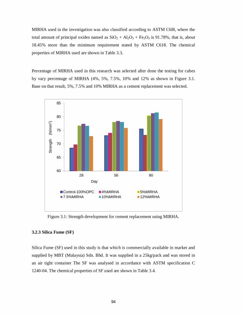
Percentage of MIRHA used in this research was selected after done the testing for cubes
by vary percentage of MIRHA (4%, 5%, 7.5%, 10% and 12% as shown in Figure 3.1.
Base on that result, 5%, 7.5% and 10% MIRHA as a cement replacement was selected.
Figure 3.1: Strength development for cement replacement using MIRHA.
3.2.3 Silica Fume (SF)
Silica Fume (SF) used in this study is that which is commercially available in market and
supplied by MBT (Malaysia) Sdn. Bhd. It was supplied in a 25kg/pack and was stored in
an air tight container The SF was analysed in accordance with ASTM specification C
1240-04. The chemical properties of SF used are shown in Table 3.4.
60
65
70
75
80
85
28 56 90
Stre
ngth
(N
/mm
2 )
Day
Control-100%OPC 4%MIRHA 5%MIRHA7.5%MIRHA 10%MIRHA 12%MIRHA
95
Table 3.4 Silica Fume (SF) Binder Properties
Oxide composition Weight (%) SF
SiO2 91.7
Al2O3 1
Fe2O3 0.9
CaO 0.68
MgO 0.8
SO3 0.87
Na2O 0.1
K2O 1.3
LOI 2.64
Noted : The sample were examined by X-ray diffraction (XRD) model Bruker AXS D8 ADVANCE. Tested done at SIRIM
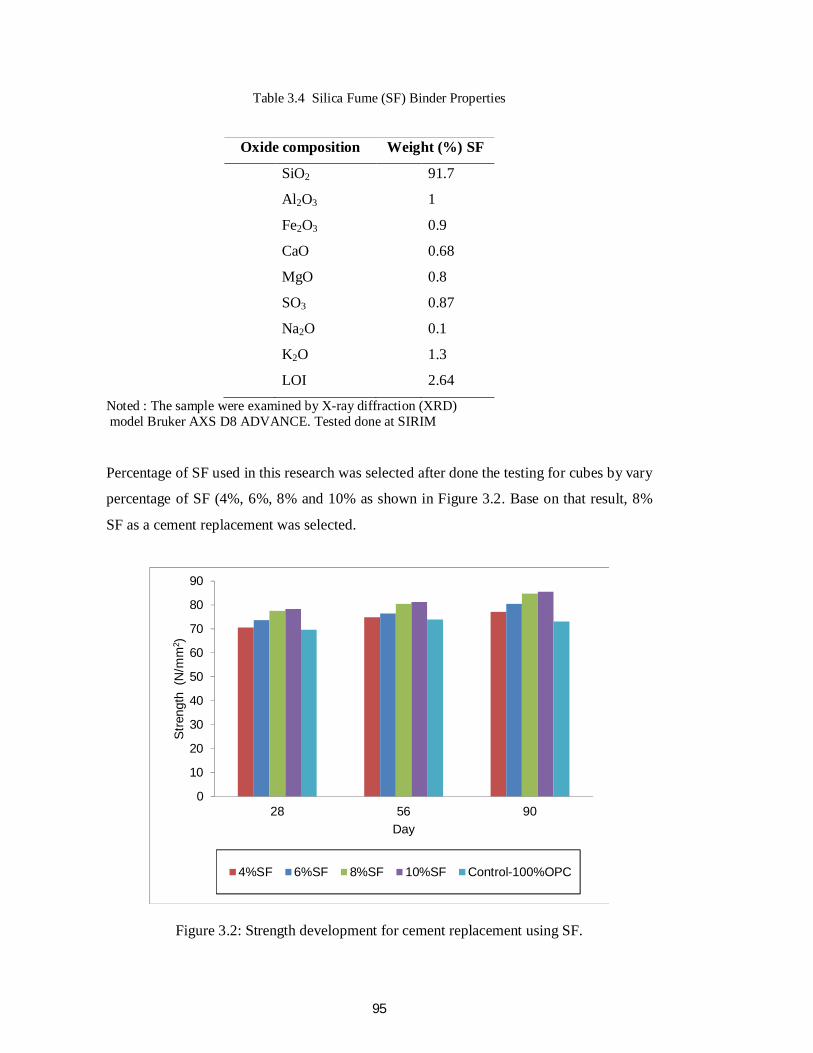
Percentage of SF used in this research was selected after done the testing for cubes by vary
percentage of SF (4%, 6%, 8% and 10% as shown in Figure 3.2. Base on that result, 8%
SF as a cement replacement was selected.
Figure 3.2: Strength development for cement replacement using SF.
0
10
20
30
40
50
60
70
80
90
28 56 90
Stre
ngth
(N
/mm
2 )
Day
4%SF 6%SF 8%SF 10%SF Control-100%OPC
96
3.2.4 Pulverized Fly Ash
PFA used in this study was PFA that produced from coal-burning power plants at Lumut,
Perak. It is a siliceous or aluminous material which possesses no binding ability by itself.
When it is in finely divided form, they can react with calcium hydroxide in the presence of
moisture to form compounds with cementing properties. During cement hydration with
water, calcium hydroxide is formed which is non-cementitious in nature.
However, when pulverized fly ash is added to calcium hydroxide, they react to produce
calcium silicate hydrates which is highly cementitious. This results in improved concrete
strength. This explains how pulverized fly ash can act as cement replacement. The studied
properties were check and compared with the ASTM specification C 618. The chemical
properties of PFA used are shown in Table 3.5.
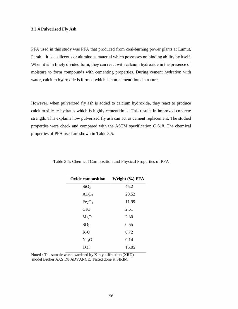
Table 3.5: Chemical Composition and Physical Properties of PFA
Oxide composition Weight (%) PFA
SiO2 45.2
Al2O3 20.52
Fe2O3 11.99
CaO 2.51
MgO 2.30
SO3 0.55
K2O 0.72
Na2O 0.14
LOI 16.05
Noted : The sample were examined by X-ray diffraction (XRD) model Bruker AXS D8 ADVANCE. Tested done at SIRIM
97
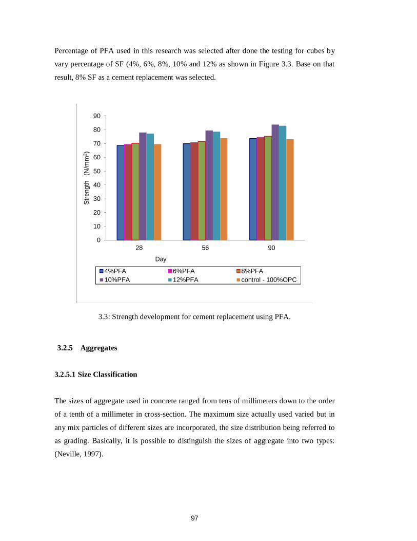
Percentage of PFA used in this research was selected after done the testing for cubes by
vary percentage of SF (4%, 6%, 8%, 10% and 12% as shown in Figure 3.3. Base on that
result, 8% SF as a cement replacement was selected.
3.3: Strength development for cement replacement using PFA.
3.2.5 Aggregates
3.2.5.1 Size Classification
The sizes of aggregate used in concrete ranged from tens of millimeters down to the order
of a tenth of a millimeter in cross-section. The maximum size actually used varied but in
any mix particles of different sizes are incorporated, the size distribution being referred to
as grading. Basically, it is possible to distinguish the sizes of aggregate into two types:
(Neville, 1997).
0
10
20
30
40
50
60
70
80
90
28 56 90
Stre
ngth
(N
/mm
2 )
Day
4%PFA 6%PFA 8%PFA10%PFA 12%PFA control - 100%OPC
98
3.2.5.2 Coarse Aggregates
The coarse aggregates used was crushed granite of angular shape and of rough surface
texture. The maximum size of the coarse aggregates was 20mm according to BS 882.
1992. The grading is shown in Table 3.6.
Table 3.6: BS 882: 1992. Grading limits for coarse aggregates
Sieve Size (mm) Percentage by mass passing sieve
BS882 grading limits for coarse aggregate
20.0 100 100
14.0 95.36 90-100
10.0 63.93 50-85
5.0 5.22 0-10
2.36 0 -
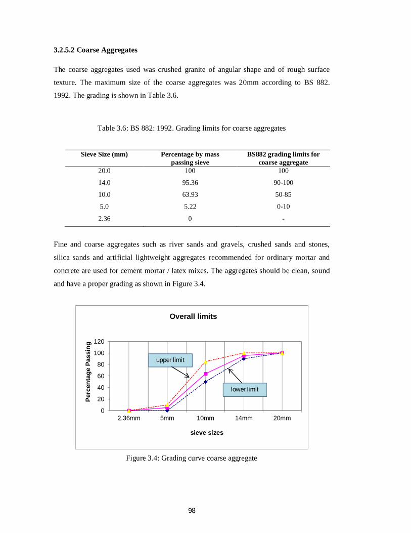
Fine and coarse aggregates such as river sands and gravels, crushed sands and stones,
silica sands and artificial lightweight aggregates recommended for ordinary mortar and
concrete are used for cement mortar / latex mixes. The aggregates should be clean, sound
and have a proper grading as shown in Figure 3.4.
Figure 3.4: Grading curve coarse aggregate
0
20
40
60
80
100
120
2.36mm 5mm 10mm 14mm 20mm
Perc
enta
ge P
assi
ng
sieve sizes
Overall limits
upper limit
lower limit
99
3.2.5.3 Fine Aggregates
The fine aggregates used were obtained from Tronoh, Perak. A sieve analysis was carried
out on representative sample in accordance with B.S. 812: 1991. Result indicated that the
sand complied with the requirement of BS 882. 1992 where it has fallen into zone overall
limits. The grading is as shown in Table 3.7.
Table 3.7: Grading for fine aggregate
Sieve Size (mm) Percentage by mass
passing sieve
BS882 grading overall limits
for fine aggregate
10 100 100
5 95.21 89-100
2.36 75.49 60-100
1.18 64.13 30-100
600 μm 44.84 15-100
300 μm 22.34 5-70
150 μm 6.05 0-15
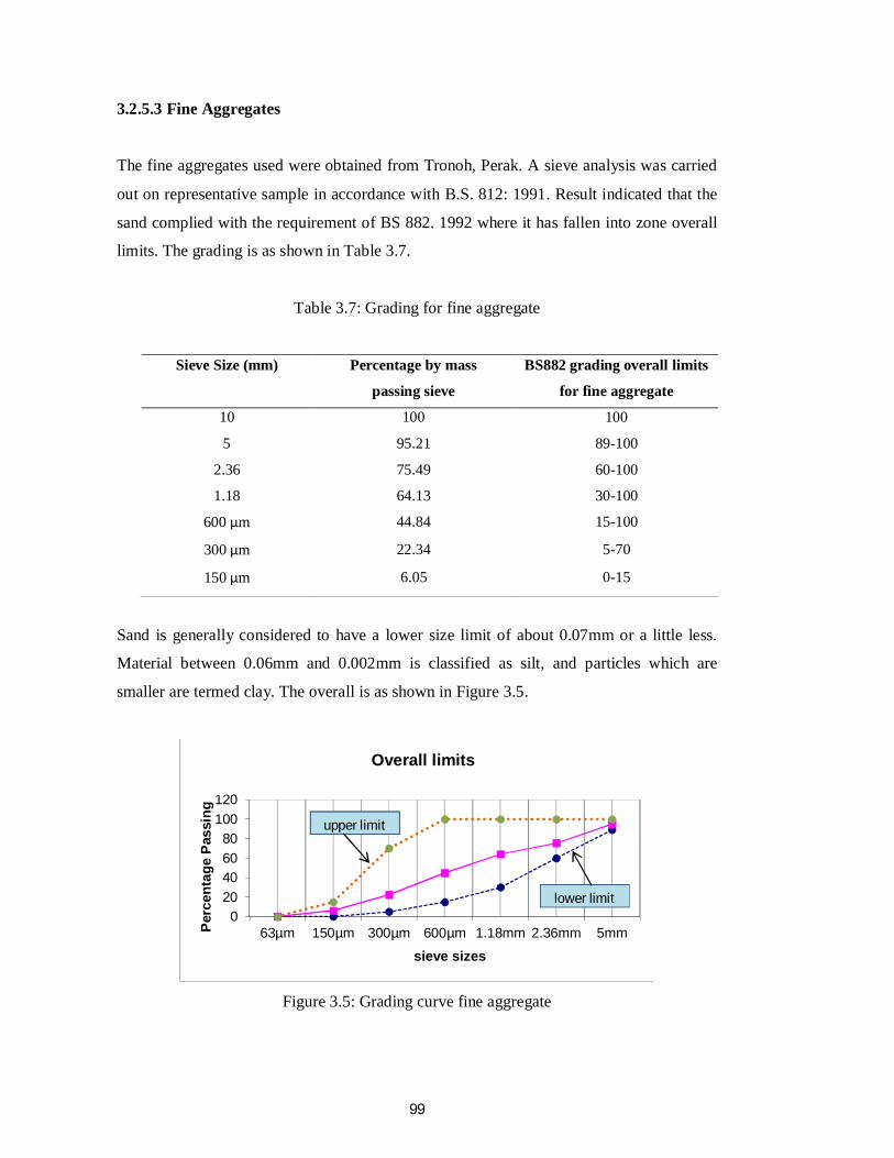
Sand is generally considered to have a lower size limit of about 0.07mm or a little less.
Material between 0.06mm and 0.002mm is classified as silt, and particles which are
smaller are termed clay. The overall is as shown in Figure 3.5.
Figure 3.5: Grading curve fine aggregate
020406080
100120
63µm 150µm 300µm 600µm 1.18mm 2.36mm 5mmPerc
enta
ge P
assi
ng
sieve sizes
Overall limits
upper limitupper limit
lower limit
100
3.2.5.4 Physical Properties
The aggregate shape and surface texture influence the aggregate-cement paste bond area
and bond strength. Irregular shape and rough surface texture increase the strength of
concrete, particularly the tensile and impact strength. Crushed aggregate improves the
cracking stress and the strength of the concrete. The effect of the surface texture is
significant when the water cement ratio is below 0.40 and is negligible when the water-
cement ratio is 0.65.
Shape can favorably influence strength by increasing the amount of surface area available
for bonding with the pastes for a given aggregate content. However, extremes in aggregate
shape may lead to high internal stress concentration and hence, easier bond failure
(Mindess,Young et al., 2008)
3.2.6 Water
The quality of water used plays a significant role to the properties of binders or concrete
mix. Impurities in water may interfere the setting time of cement or binders. It may also
adversely affect the strength of concrete or cause staining the concrete surface and may
also lead to corrosion of the reinforcement in reinforced concrete system. Mixing water
should not contain undesirable organic or inorganic proportions but there is no standard
prescription on the quality of mixing water. Lembaga Air Perak (LAP) specifications
stated the quality of mixing water is the water that is fit for drinking. In this investigation,
drinking tap water from the UTP concrete lab used free water (BS 3148: 1980),
3.2.7 Superplasticizer
Superplasticizer is an admixture used in concrete mixing to increase the workability of
concrete especially in a concrete mix with low water/cement ratio. Superplasticizer also
has the ability to restrain bleeding and segregation without abnormal retardation and air-
entrainment to the concrete mix.
101
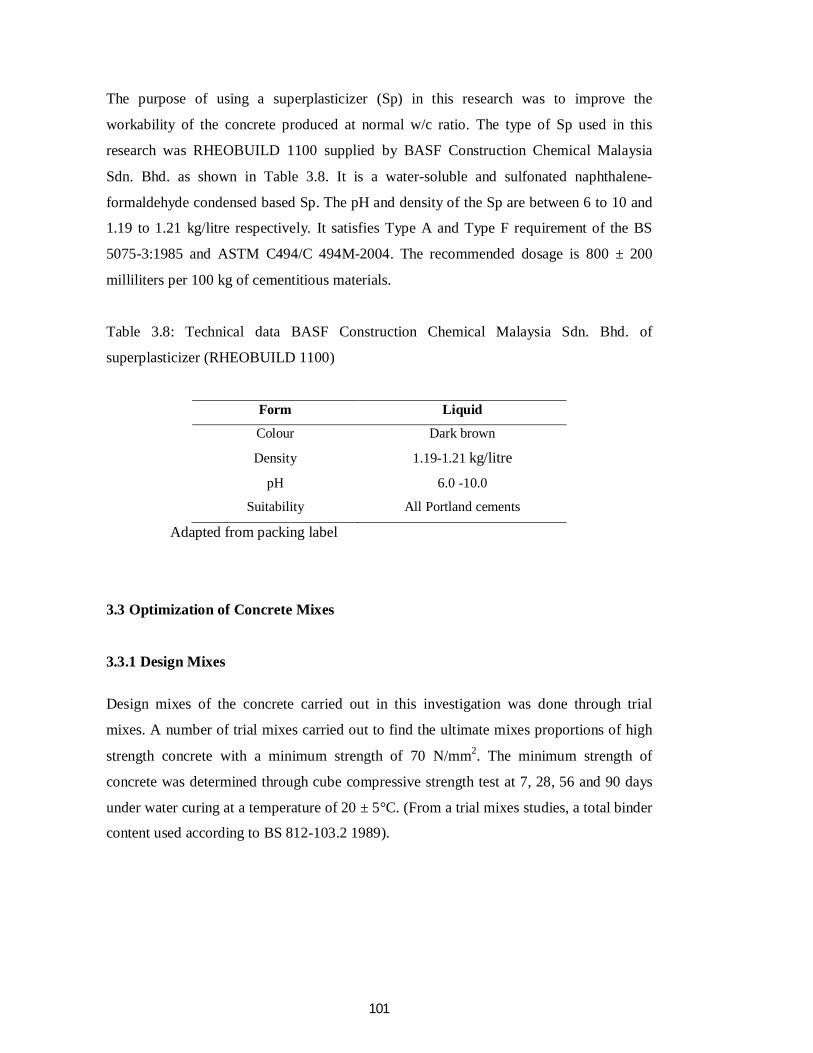
The purpose of using a superplasticizer (Sp) in this research was to improve the
workability of the concrete produced at normal w/c ratio. The type of Sp used in this
research was RHEOBUILD 1100 supplied by BASF Construction Chemical Malaysia
Sdn. Bhd. as shown in Table 3.8. It is a water-soluble and sulfonated naphthalene-
formaldehyde condensed based Sp. The pH and density of the Sp are between 6 to 10 and
1.19 to 1.21 kg/litre respectively. It satisfies Type A and Type F requirement of the BS
5075-3:1985 and ASTM C494/C 494M-2004. The recommended dosage is 800 ± 200
milliliters per 100 kg of cementitious materials.
Table 3.8: Technical data BASF Construction Chemical Malaysia Sdn. Bhd. of
superplasticizer (RHEOBUILD 1100)
Form Liquid
Colour Dark brown
Density 1.19-1.21 kg/litre
pH 6.0 -10.0
Suitability All Portland cements
Adapted from packing label
3.3 Optimization of Concrete Mixes
3.3.1 Design Mixes Design mixes of the concrete carried out in this investigation was done through trial
mixes. A number of trial mixes carried out to find the ultimate mixes proportions of high
strength concrete with a minimum strength of 70 N/mm2. The minimum strength of
concrete was determined through cube compressive strength test at 7, 28, 56 and 90 days
under water curing at a temperature of 20 ± 5°C. (From a trial mixes studies, a total binder
content used according to BS 812-103.2 1989).
102
3.3.1.1 Multiple Blended Binders
In recent years, it has been reported that multiple blended binders cement could
substantially improve the performance of concrete compared with the conventional binary
blended cements or regular Portland cement. Multiple blended binders cement consisting
of Portland cement, granulated OPC+SF+PFA was developed in Japan for mass concrete
construction due to its very low heat of hydration(Yamamoto et al.,1982) The addition of
PFA can increase workability and reduce bleeding of slag cement concrete.
By incorporating SF in slag cement or PFA cement the ternary OPC+SF+PFA blended
cements can be developed and commercially manufactured. Similar to the effect of SF
addition in Portland cement, PFA in OPC+SF+PFA system may have water reducing
effect depending on its quality that may totally or partially compensate the increased water
requirement caused by SF. The addition of SF could only slightly increase the early
strength of OPC+SF+PFA system cement due to pozzolanic reaction of SF at the early age
of hydration process.
On the other hand, when silica fume is added to fly ash concrete, the rate of change of
elastic modulus is reduced. The incorporation of a combination of finely grounded PFA
and SF with OPC was reported to produce higher compressive strengths at all ages than
their binary blends.
3.3.1.2 Pozzolanic Material
Pozzolanic materials are materials that contain silica or silica alumina that will react with
CaO with the present of moisture to create cementitous properties. In HSC, the pozzolanic
materials were used to enhance the concrete properties and its durability.
A study on the pozzolanic materials properties is important to identify its quality before it
can be used as cement replacement materials. The pozzo1anic materials used in this
investigation are pulverized fly ash (PFA), silica fume (SF) and microwave incinerator
rice husk ash (MIRHA).
103
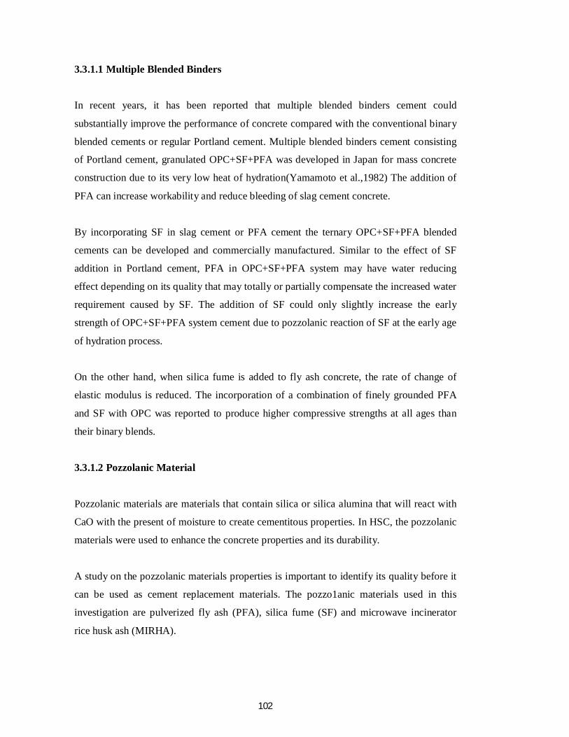
3.4 Mixes Proportion of Multiple Blended Binders
16 batches of concrete mixes containing 100% OPC as control mix and 5%, 7.5%, 10%
MIRHA, 8%SF and 10%PFA replacement level of pozzolanic materials as multiple
blended binders cement systems was prepared. The materials were proportioned, so that
the concrete mixes will achieve 28 days strength of greater than 68 N/mm2. A total binder
content of 825 kg/m' and a constant water/binder ratio 0.35 is used. Details of the cement
mixes proportions are shown in Table 3.9.
Table 3.9: Preparation for concrete cubes
Item Mix No. of cubes
Testing involve
1 100OPC 15 3,7,28,56,90 days
2 95OPC+5MIRHA 15 3,7,28,56,90 days
3 92.5OPC+7.5MIRHA 15 3,7,28,56,90 days
4 90OPC+10MIRHA 15 3,7,28,56,90 days
5 92OPC+8SF 15 3,7,28,56,90 days
6 87OPC+5MIRHA+8SF 15 3,7,28,56,90 days
7 84.5OPC+7.5MIRHA+8SF 15 3,7,28,56,90 days
8 82OPC+10MIRHA+8SF 15 3,7,28,56,90 days
9 90OPC+10PFA 15 3,7,28,56,90 days
10 85OPC+5MIRHA+10PFA 15 3,7,28,56,90 days
11 82.5OPC+7.5MIRHA+10PFA 15 3,7,28,56,90 days
12 80OPC+10MIRHA+10PFA 15 3,7,28,56,90 days
13 82OPC+8SF+10PFA 15 3,7,28,56,90 days
14 77OPC+5MIRHA+8SF+10PFA 15 3,7,28,56,90 days
15 74.4OPC+7.5MIRHA+8SF+10PFA 15 3,7,28,56,90 days
16 72OPC+10MIRHA+8SF+10PFA 15 3,7,28,56,90 days
Total 240 RH, UPV, Compressive
A concrete mix without any cement replacement materials was prepared as a control mix.
All the concrete materials were mixed in the concrete mixer for 4 minutes. The concrete
104
mixes were than cast into steel cube moulds (150 x 150 x 150 mm) in three layers and
each layer was compacted using a vibrating table. A total of 240 nos. concrete cubes were
prepared as shown in Table 3.9 and all the cubes have been cured in water bath at 20 ±
5°C for 3, 7, 28, 56 and 90 days. At all testing ages, three cubes tested for compressive
strength in accordance with British Standard specifications for concrete.
Based on the compressive strength result of prepared samples using blended binders
cement systems, the optimum replacement level of pozzolanic materials to OPC was
decided as binders mixes proportions and used in preparing a multiple blended binders
cement systems.
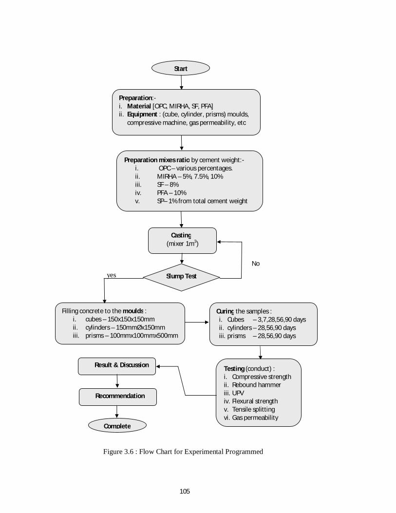
The multiple blended binders cement systems containing OPC, PFA, MIRHA and one of
the three other pozzolanic materials are then used as binder materials in preparing HSC
mixes. The same concrete designed mixes proportion and procedure as stated above,
followed by using multiple blended binders cement systems as binder can be derived from
Figure 3.6.
105
yes
Figure 3.6 : Flow Chart for Experimental Programmed
Start
Preparation:- i. Material [OPC, MIRHA, SF, PFA] ii. Equipment : (cube, cylinder, prisms) moulds,
compressive machine, gas permeability, etc
Preparation mixes ratio by cement weight:- i. OPC – various percentages. ii. MIRHA – 5%, 7.5%, 10% iii. SF – 8% iv. PFA – 10% v. SP– 1% from total cement weight vi. SP – 1% for total cement weight
Casting (mixer 1m3)
Slump Test
Filling concrete to the moulds : i. cubes – 150x150x150mm ii. cylinders – 150mmØx150mm iii. prisms – 100mmx100mmx500mm
Curing the samples : i. Cubes – 3,7,28,56,90 days ii. cylinders – 28,56,90 days iii. prisms – 28,56,90 days
Testing (conduct) : i. Compressive strength ii. Rebound hammer iii. UPV iv. Flexural strength v. Tensile splitting vi. Gas permeability
Result & Discussion
Recommendation
Complete
No
106
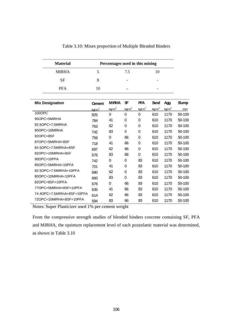
Table 3.10: Mixes proportion of Multiple Blended Binders
Material Percentages used in this mixing
MIRHA 5 7.5 10
SF 8 - -
PFA 10 - -
Mix Designation
100OPC 95OPC+5MIRHA 92.5OPC+7.5MIRHA 90OPC+10MIRHA 92OPC+8SF 87OPC+5MIRHA+8SF 84.5OPC+7.5MIRHA+8SF 82OPC+10MIRHA+8SF 90OPC+10PFA 85OPC+5MIRHA+10PFA 82.5OPC+7.5MIRHA+10PFA 80OPC+10MIRHA+10PFA 82OPC+8SF+10PFA 77OPC+5MIRHA+8SF+10PFA 74.4OPC+7.5MIRHA+8SF+10PFA 72OPC+10MIRHA+8SF+10PFA
Cement kg/m3
825 784 763 742 759 718 697 676 742 701 680 660 676 635 614 594
MIRHA kg/m3
0 41 62 83 0 41 62 83 0 41 62 83 0 41 62 83
SF kg/m3
0 0 0 0 66 66 66 66 0 0 0 0 66 66 66 66
PFA kg/m3
0 0 0 0 0 0 0 0 83 83 83 83 83 83 83 83
Sand kg/m3
610 610 610 610 610 610 610 610 610 610 610 610 610 610 610 610
Agg. kg/m3
1170 1170 1170 1170 1170 1170 1170 1170 1170 1170 1170 1170 1170 1170 1170 1170
Slump mm
50-100 50-100 50-100 50-100 50-100 50-100 50-100 50-100 50-100 50-100 50-100 50-100 50-100 50-100 50-100 50-100
Notes: Super Plasticizer used 1% per cement weight From the compressive strength studies of blended binders concrete containing SF, PFA
and MIRHA, the optimum replacement level of each pozzolanic material was determined,
as shown in Table 3.10
107
3.5 Test Procedures
3.5.1 Workability Test on Fresh Concrete
In this particular research work, only the slump test method was used to measure the
workability of fresh concrete mixes. The slump test as prescribed in BS EN 12350-2:2000
consists of a tamping rod and a truncated cone of 300 mm height and 100 mm diameter at
the top and 200 mm diameter at the bottom, as shown in Table 3.11. The cone was placed
on a smooth surface and was filled up with three layers of concrete. Each layer was
tamped 25 times with a standard 16 mm diameter steel rod rounded at the end. The top
surface of the concrete will strike off by means of a swing and rolling motion of the
tamping rod. Immediately after filling, the cone was slowly lifted and the unsupported
concrete cone slumps down by its own weight. The decrease in the height of the slumped
cone is called the slump of concrete.
3.5.2 Mechanical Tests on Hardened Concrete
The mechanical tests conducted on hardened concrete were the destructive tests which
comprised compressive strength, flexural test, tensile splitting strength and equivalent
cube compressive strength. Meanwhile, the non-destructive tests were the ultrasonic pulse
velocity (UPV), rebound hammer (RH) and gas permeability. The strengths of the
concrete specimen were tested the ages of cubes on 3, 7, 28, 56 and 90 days under water
curing conditions, except for flexural strength test and tensile splitting strength test in
which the strengths were taken at the ages of 28, 56 and 90 days. Under water curing, the
temperature in water tank with a temperature 27 ±0.50C. The making, curing of and testing
of the specimens for the mechanical tests were conducted at the concrete laboratory of the
Department of Civil Engineering, UTP and UiTM.
108
3.5.2.1 Compressive Strength
The most common test conducted on hardened concrete is the compressive strength test.
Cube specimens l50mm x 150mmx l50mm were prepared and tested following BS EN
12390-1:2000 and BS EN 12390-3:2002. The test machine used was an ELE (Engineering
Laboratory Equipment) testing machine with a load capacity of 3000 kN running at a pace
rate of 3.0 KN/sec., in accordance to BS EN 12390-4:2000. In determining the strength of
the mixes, the specimens were tested at the ages of 3, 7, 28, 56 and 90 days, under water
curing conditions. For the compressive strength, the series involved were the OPC,
5%MIRHA, 7.5%MIRHA, 10%MIRHA, 8%SF and 10%PFA.
3.5.2.2 Flexural Strength Test
The flexural strength, as modulus of rupture, is essential to estimate the load at which
concrete members may crack. For that reason, the modulus of rupture at failure was
conducted on the concrete prism. Prism specimens of 100mm x l00mm x 500mm were
prepared and tested according BS EN 12390-l:2000 and BS EN 12390-5:2000. The
specimens were tested the ages of prism on 28, 56 and 90 days, under water curing
conditions. For the modulus of rupture, the series involved were the OPC, 5%MIRHA,
7.5%MIRHA, 10%MIRHA, 8%SF and 10%PFA.
The modulus of rupture was determined by means of a constant moment in the central
zone of the specimen using a two-point loading of the EL 33-6090 flexural testing
machine. Load was applied steadily and continuously at the rate of 0.067 kN/sec. until
failure. The flexural tensile strength expressed in terms of the modulus of rupture, fr
(N/mm2), is the maximum stress at rupture computed from the flexural formula given by
BS EN 12390-5:2000 as shown below:-
109
fr = F x L . …………Eq. 3.1
b x d2
where,
fr = modulus of rupture, (N/mm2)
F = maximum d of load, (N)
L = span length between supporting rollers, (mm)
b = width of the cross section, (mm)
d = depth of the cross section, (mm)
3.5.2.3 Tensile Splitting Strength
The most common test for estimating the tensile strength of concrete is the splitting
tension test as prescribed in BS EN 12390-6:2000. Cylindrical concrete specimens sized
150mm diameter and length of 150 mm of OPC, 5%MIRHA, 7.5%MIRHA, 10%MIRHA,
8%SF and 10%PFA mixes were prepared as in accordance to BS EN 12390-1:2000. The
specimens were tested at the ages of 28, 56 and 90 days, under water curing conditions.
The calculation for tensile splitting strength, fct in N/mm2 was computed from the formula
given by BS EN 12390-6:2000 as follows:-
Fct = 2F . …………..Eq.3.2
x L x d
where
fct = tensile splitting strength, (N/mm2)
F = maximum d of load, (N)
L = length of specimen, (mm)
D = diameter of specimen, (mm)
110
3.5.3 Non-Destructive Tests on Hardened Concrete
The range of availability for non-destructive tests are extensive, thus the selection was
based on the material properties. In this research work, the tests chosen were to measure
the surface hardness and the ultrasonic pulse velocity.
3.5.3.1 Ultrasonic Pulse Velocity (UPV)
This test determines velocity of longitudinal wave, as a measurement the time taken by the
pulse to travel a measured distance through the concrete specimen. It is related to the
density of the concrete. For a given aggregate and a given richness of the concrete is
affected by changes in the hardened cement or MIRHA:SF:PFA concrete, such as a fixed
in the w/c ratio, which affects the modulus of elasticity of the hardened cement or
OPC:MIRHA:SF:PFA concrete as well. Moisture condition of the concrete affects the
pulse velocity, which arises from the fact that pulse travels faster through a water-filled
void than through an air-filled void. From the value of pulse velocity, the quality of
concrete can be predicted.
o
This test was conducted in accordance to BS EN 12504-4:2004. Test was subjected to
150mm cube specimens the ages of 28, 56 and 90 days under water curing conditions. The
series involved were the OPC:MIRHA:SF:PFA.
The instrument used to determine the pulse velocity is 'Pundit Plus' supplied by CNS
Farwell. In this research work, the determination of the pulse velocity was by direct
transmission, in which the transducers were placed opposite to each other, so that the
maximum energy of the pulse is transmitted and the accuracy of the velocity determination
could be achieved. An electro-acoustical transducer held in contact with the surface of the
produced pulse of longitudinal vibration. After traversing a known path length in the
concrete specimen (150 mm), the pulses of vibrations were converted into an electrical
signal by a second transducer. The digital indicating device measures the time interval for
the pulse to travel between the two transducers. In ensuring the vibration of the transducer
being transmitted to the concrete by close contact, grease was applied on the contact faces
111
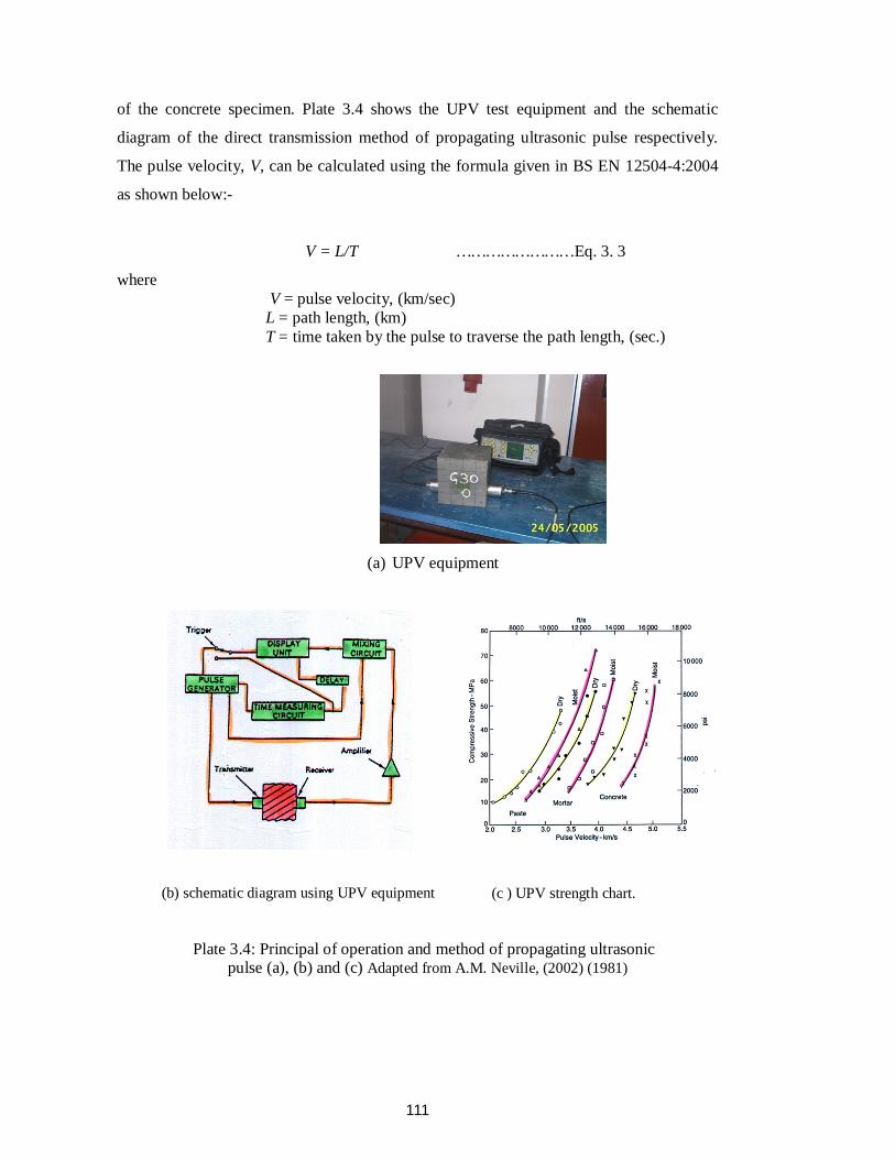
of the concrete specimen. Plate 3.4 shows the UPV test equipment and the schematic
diagram of the direct transmission method of propagating ultrasonic pulse respectively.
The pulse velocity, V, can be calculated using the formula given in BS EN 12504-4:2004
as shown below:-
V = L/T ……………………Eq. 3. 3
where V = pulse velocity, (km/sec) L = path length, (km) T = time taken by the pulse to traverse the path length, (sec.)
(a) UPV equipment
(b) schematic diagram using UPV equipment
(c ) UPV strength chart.
Plate 3.4: Principal of operation and method of propagating ultrasonic pulse (a), (b) and (c) Adapted from A.M. Neville, (2002) (1981)
112
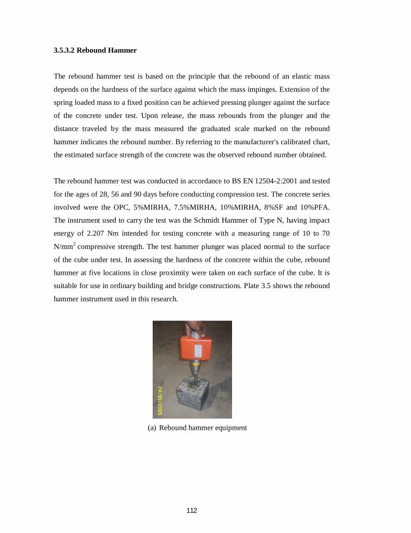
3.5.3.2 Rebound Hammer
The rebound hammer test is based on the principle that the rebound of an elastic mass
depends on the hardness of the surface against which the mass impinges. Extension of the
spring loaded mass to a fixed position can be achieved pressing plunger against the surface
of the concrete under test. Upon release, the mass rebounds from the plunger and the
distance traveled by the mass measured the graduated scale marked on the rebound
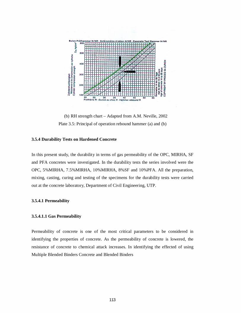
hammer indicates the rebound number. By referring to the manufacturer's calibrated chart,
the estimated surface strength of the concrete was the observed rebound number obtained.
The rebound hammer test was conducted in accordance to BS EN 12504-2:2001 and tested
for the ages of 28, 56 and 90 days before conducting compression test. The concrete series
involved were the OPC, 5%MIRHA, 7.5%MIRHA, 10%MIRHA, 8%SF and 10%PFA.
The instrument used to carry the test was the Schmidt Hammer of Type N, having impact
energy of 2.207 Nm intended for testing concrete with a measuring range of 10 to 70
N/mm2 compressive strength. The test hammer plunger was placed normal to the surface
of the cube under test. In assessing the hardness of the concrete within the cube, rebound
hammer at five locations in close proximity were taken on each surface of the cube. It is
suitable for use in ordinary building and bridge constructions. Plate 3.5 shows the rebound
hammer instrument used in this research.
(a) Rebound hammer equipment
113
(b) RH strength chart – Adapted from A.M. Neville, 2002
Plate 3.5: Principal of operation rebound hammer (a) and (b)
3.5.4 Durability Tests on Hardened Concrete
In this present study, the durability in terms of gas permeability of the OPC, MIRHA, SF
and PFA concretes were investigated. In the durability tests the series involved were the
OPC, 5%MIRHA, 7.5%MIRHA, 10%MIRHA, 8%SF and 10%PFA. All the preparation,
mixing, casting, curing and testing of the specimens for the durability tests were carried
out at the concrete laboratory, Department of Civil Engineering, UTP.
3.5.4.1 Permeability
3.5.4.1.1 Gas Permeability
Permeability of concrete is one of the most critical parameters to be considered in
identifying the properties of concrete. As the permeability of concrete is lowered, the
resistance of concrete to chemical attack increases. In identifying the effected of using
Multiple Blended Binders Concrete and Blended Binders
114
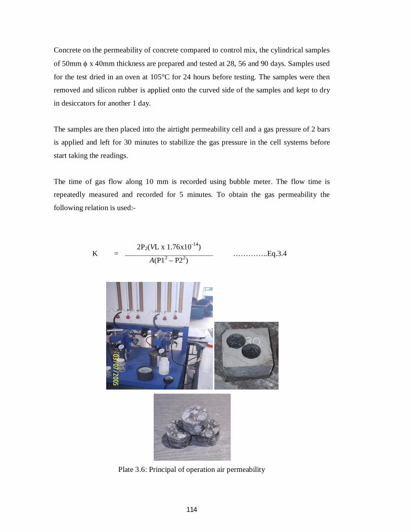
Concrete on the permeability of concrete compared to control mix, the cylindrical samples
of 50mm x 40mm thickness are prepared and tested at 28, 56 and 90 days. Samples used
for the test dried in an oven at 105°C for 24 hours before testing. The samples were then
removed and silicon rubber is applied onto the curved side of the samples and kept to dry
in desiccators for another 1 day.
The samples are then placed into the airtight permeability cell and a gas pressure of 2 bars
is applied and left for 30 minutes to stabilize the gas pressure in the cell systems before
start taking the readings.
The time of gas flow along 10 mm is recorded using bubble meter. The flow time is
repeatedly measured and recorded for 5 minutes. To obtain the gas permeability the
following relation is used:-
K = 2P2(VL x 1.76x10⁻¹⁴)
…………..Eq.3.4 A(P12 – P22)
Plate 3.6: Principal of operation air permeability
115
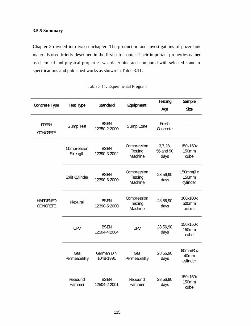
3.5.5 Summary
Chapter 3 divided into two subchapter. The production and investigations of pozzolanic
materials used briefly described in the first sub chapter. Their important properties named
as chemical and physical properties was determine and compared with selected standard
specifications and published works as shown in Table 3.11.
Table 3.11: Experimental Program
Concrete Type Test Type Standard Equipment Testing
Age
Sample
Size
FRESH
CONCRETE Slump Test BS EN
12350-2:2000 Slump Cone Fresh Concrete
-
Compression Strength
BS EN 12390-3:2002
Compression
Testing Machine
3,7,28, 56 and 90
days
150x150x 150mm
cube
Split Cylinder BS EN 12390-6:2000
Compression
Testing Machine
28,56,90 days
150mmØ x 150mm cylinder
HARDENED CONCRETE
Flexural BS EN 12390-5:2000
Compression
Testing Machine
28,56,90 days
100x100x 500mm prisms
UPV BS EN 12504-4:2004
UPV 28,56,90 days
150x150x 150mm
cube
Gas Permeabilitty
German DIN 1048-1991
Gas Permeabilitty
28,56,90 days
50mmØ x
40mm cylinder
Rebound Hammer
BS EN 12504-2:2001
Rebound Hammer
28,56,90 days
150x150x 150mm
cube
116
In second sub chapter, the investigation on the optimum mixes proportion of
blended binders concrete in designing multiple blended binders utilizing local
waste product was performed. The potential of using multiple blended binders in
obtaining High Strength Concrete mixes also determined.
The chemical composition were studies and outlined that all pozzolanic materials
prepared and used is satisfied the standard specification and other published works.
Investigation on the optimum replacement level of pozzolanic materials used found
that the optimum replacement level of SF, PFA and MIRHA is 10% while 30%
replacement level to OPC is the optimum replacement level of SF. The mixes
proportions of multiple blended binders were obtained through mixing the SF and
PFA with MIRHA at a specific proportion determine before. The utilization of
multiple blended binders concrete in achieving high strength concrete mixes found
to be potential even at a replacement level of 28% to OPC.