Embed Size (px)
Citation preview
Chapter 3
The Cellular Concept –System Design Fundamentals
Cellular Communications
History • The design objective of early mobile radio systems was to achieve a large
coverage area by using a single, high powered transmitter with an antenna mounted on a tall tower.
• The limited capacity of the first mobile radio-telephone services was related to the spectrum used…not much sharing and a lot of bandwidth dedicated to a single call. It had good coverage and no interference since it is impossible to reuse the same frequency.
• The cellular concept addressed many of the shortcomings of the first mobile telephones including the frequency reuse and the allocation of spectrum to a single user
• In 1968, Bell Labs proposed the cellular telephony concept to the FCC
• It was approved for a while before it was deployed.
– FCC allocated spectrum (took away TV UHF channels 70-83) in the 825-845 MHz and 870-890 MHz bands
– AT&T put up a developmental system in Chicago
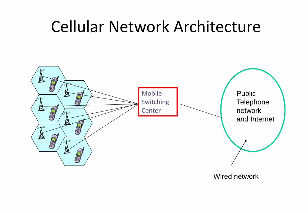
Cellular Network Architecture
Mobile Switching Center
Public
Telephone
network
and Internet
Wired network
Cellular Concept
• Areas divided into cells.
• A system approach, no major technological changes.
• A few hundred meters in some cities, 10s km at country side.
• Each served by base station with lower power transmitter.
• Each gets portion of total number of channels.
• Neighboring cells assigned different groups of channels, interference minimized.
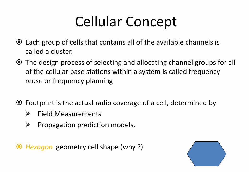
Cellular Concept Each group of cells that contains all of the available channels is
called a cluster.
The design process of selecting and allocating channel groups for all of the cellular base stations within a system is called frequency reuse or frequency planning
Footprint is the actual radio coverage of a cell, determined by
Field Measurements
Propagation prediction models.
Hexagon geometry cell shape (why ?)
Base Station Locations When using hexagons to model coverage areas, base stations
transmitters are located at
The center of the cell center-excited cells.
Omni-directional antennas ate used
The three of the six cell vertices edge-excited cells.
Sectored directional antennas
Most system designs permit a base station to be positioned up to ¼ the cell radius away from the ideal location.
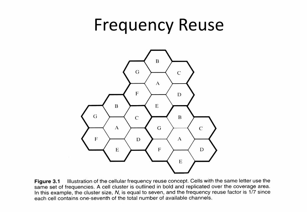
Frequency Reuse
Frequency Reuse
• Adjacent cells assigned different frequencies to avoid interference or crosstalk.
• Objective is to reuse frequency in nearby cells
– 10 to 60 frequencies assigned to each cell
– transmission power controlled to limit power at that frequency escaping to adjacent cells
– the issue is to determine how many cells must intervene between two cells using the same frequency
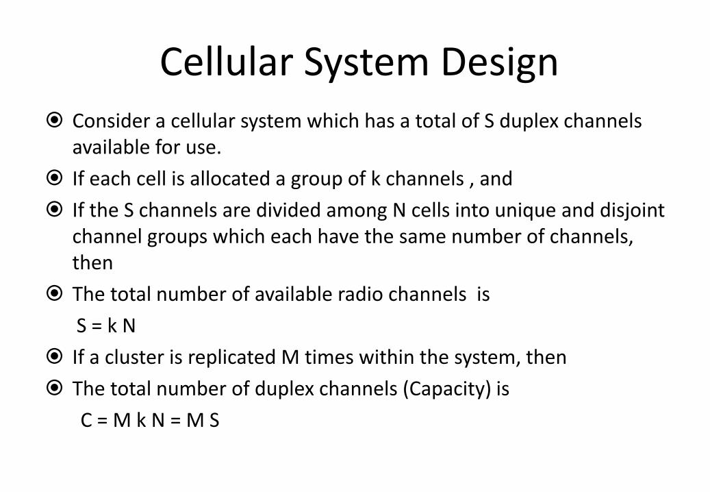
Cellular System Design Consider a cellular system which has a total of S duplex channels
available for use.
If each cell is allocated a group of k channels , and
If the S channels are divided among N cells into unique and disjoint channel groups which each have the same number of channels, then
The total number of available radio channels is
S = k N
If a cluster is replicated M times within the system, then
The total number of duplex channels (Capacity) is
C = M k N = M S
Design of Cluster
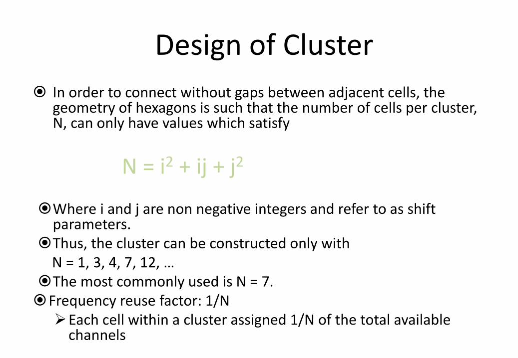
In order to connect without gaps between adjacent cells, the geometry of hexagons is such that the number of cells per cluster, N, can only have values which satisfy
N = i2 + ij + j2
Where i and j are non negative integers and refer to as shift parameters.
Thus, the cluster can be constructed only with N = 1, 3, 4, 7, 12, … The most commonly used is N = 7. Frequency reuse factor: 1/N Each cell within a cluster assigned 1/N of the total available
channels
Design of Cluster
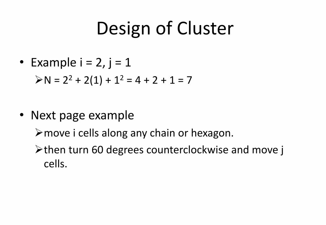
• Example i = 2, j = 1
N = 22 + 2(1) + 12 = 4 + 2 + 1 = 7
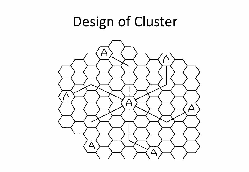
• Next page example
move i cells along any chain or hexagon.
then turn 60 degrees counterclockwise and move j cells.
Design of Cluster
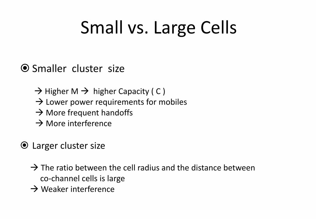
Small vs. Large Cells
Smaller cluster size Higher M higher Capacity ( C )
Lower power requirements for mobiles More frequent handoffs More interference
Larger cluster size The ratio between the cell radius and the distance between co-channel cells is large Weaker interference
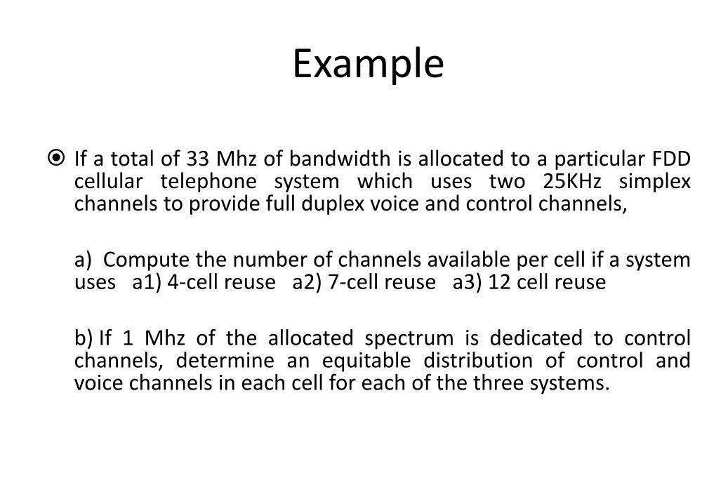
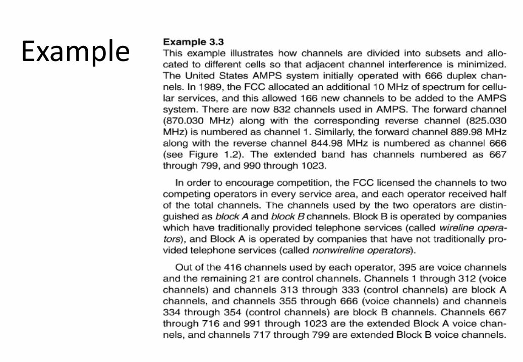
Example
If a total of 33 Mhz of bandwidth is allocated to a particular FDD
cellular telephone system which uses two 25KHz simplex channels to provide full duplex voice and control channels, a) Compute the number of channels available per cell if a system uses a1) 4-cell reuse a2) 7-cell reuse a3) 12 cell reuse
b) If 1 Mhz of the allocated spectrum is dedicated to control channels, determine an equitable distribution of control and voice channels in each cell for each of the three systems.
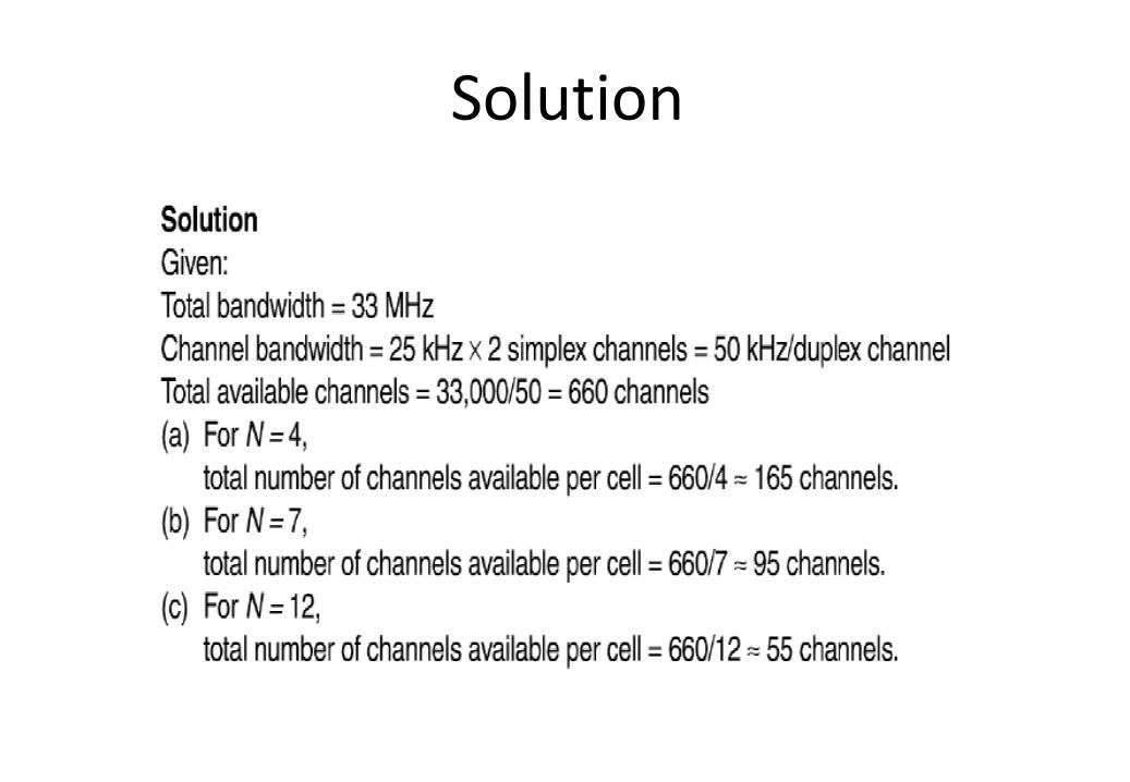
Solution
Solution
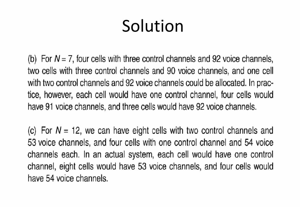
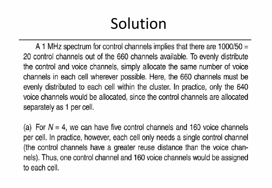
Solution

Channel Assignment Strategies
Fixed Channel Assignments
• Each cell is allocated a predetermined set of voice channels.
• If all the channels in that cell are occupied, the call is blocked, and the subscriber does not receive service.
• Variation includes a borrowing strategy: a cell is allowed to borrow channels from a neighboring cell if all its own channels are occupied.
• This is supervised by the Mobile Switch Center.
Channel Assignment Strategies
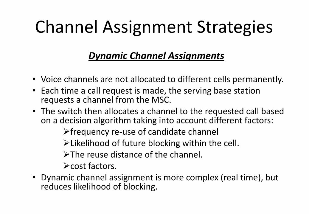
Dynamic Channel Assignments
• Voice channels are not allocated to different cells permanently. • Each time a call request is made, the serving base station
requests a channel from the MSC. • The switch then allocates a channel to the requested call based
on a decision algorithm taking into account different factors: frequency re-use of candidate channel Likelihood of future blocking within the cell. The reuse distance of the channel. cost factors.
• Dynamic channel assignment is more complex (real time), but reduces likelihood of blocking.
Handoff
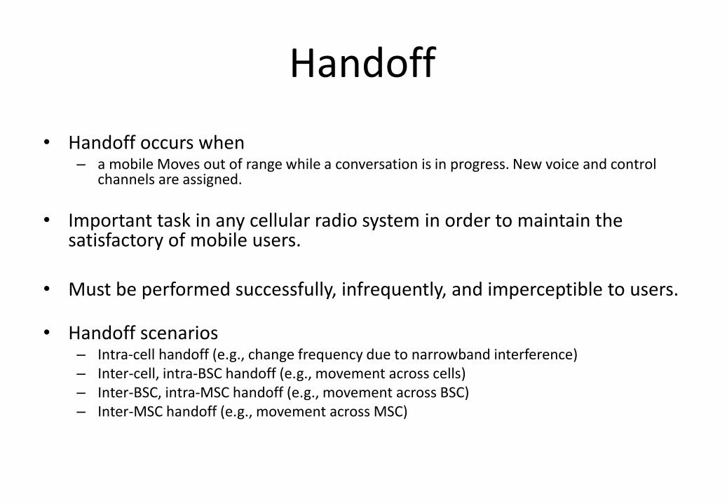
• Handoff occurs when – a mobile Moves out of range while a conversation is in progress. New voice and control
channels are assigned.
• Important task in any cellular radio system in order to maintain the satisfactory of mobile users.
• Must be performed successfully, infrequently, and imperceptible to users.
• Handoff scenarios – Intra-cell handoff (e.g., change frequency due to narrowband interference) – Inter-cell, intra-BSC handoff (e.g., movement across cells) – Inter-BSC, intra-MSC handoff (e.g., movement across BSC) – Inter-MSC handoff (e.g., movement across MSC)
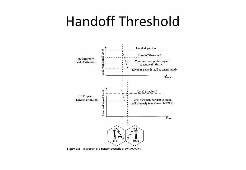
Handoff Threshold
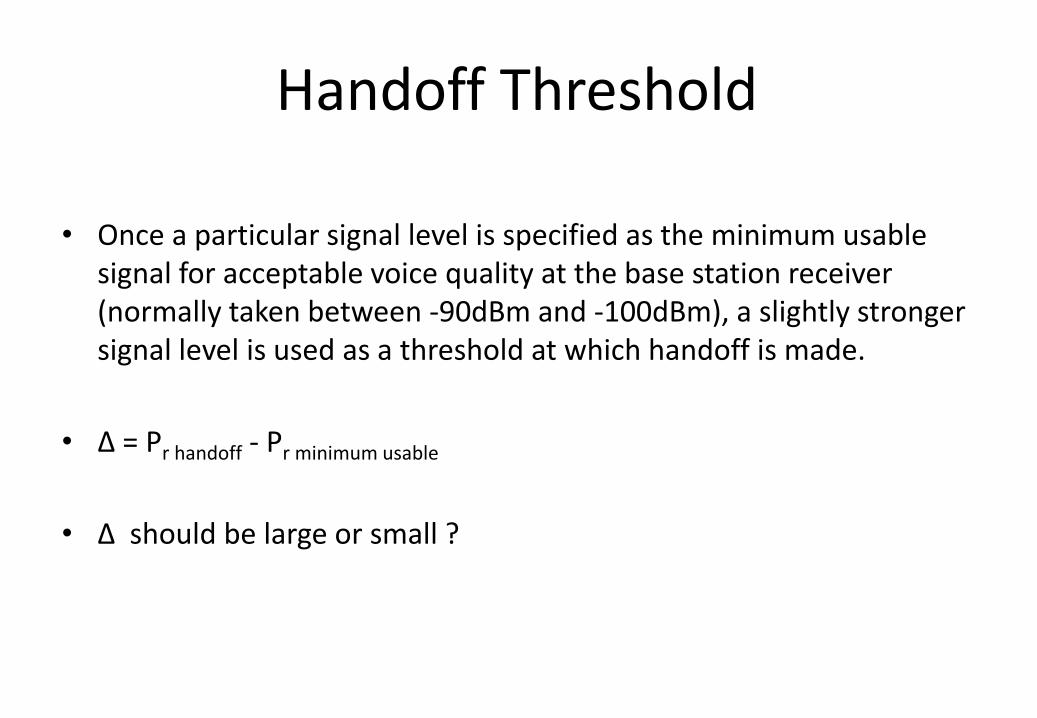
• Once a particular signal level is specified as the minimum usable
signal for acceptable voice quality at the base station receiver (normally taken between -90dBm and -100dBm), a slightly stronger signal level is used as a threshold at which handoff is made.
• Δ = Pr handoff - Pr minimum usable
• Δ should be large or small ?
Handoff Threshold
Dropped Calls
• Dropped calls may happen for two reasons – When the threshold Δ is set too small for the handoff time in the
system
– When there is an excessive delay by MSC in assigning a handoff which may occur during high traffic conditions due to
computational loading at the MSC
The fact that no channels arw available on any of the nearby base stations.
Dwell time
• Dwell time is the time over which a call may be maintained within a cell without hand off.
• The dwell time is governed by the following factors : – Propagation
– Interference
– Distance between the subscriber and the base station.
Handoff Mechanisms
• Network Controlled Handoff (NCHO) – in first generation cellular system, each base station constantly
monitors signal strength from mobiles in its cell – A spare receiver in each base station is used to scan and
determine signal strengths of mobile users which are in neighboring cells (locator receiver)
– Handoff is initiated when the power received from the base station of a neighboring cell begins to exceed the power received from the current base station by a certain level or for a certain period of time.
– Based on the measures, MSC decides if handoff necessary – Mobile plays passive role in process – Burden on MSC
Handoff Mechanisms
• Mobile Assisted Handoff (MAHO) – present in second generation systems
– mobile measures received power from surrounding base stations and report to serving base station
– handoff initiated when power received from a neighboring cell exceeds current value by a certain level or for a certain period of time
– faster since measurements made by mobiles, MSC don’t need monitor signal strength
Prioritizing Handoffs
• Dropping a call is more annoying than line busy
• Guard channel concept – Reserve some channels for handoffs
– Waste of bandwidth
– Dynamic channel assignments strategies can offer efficient spectrum utilization.
• Queuing of handoff requests – There is a gap between time for handoff and time to drop.
– Tradeoff between the decrease in probability of forced termination and total carried traffic.
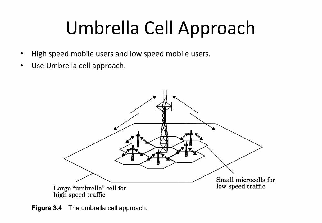
Umbrella Cell Approach • High speed mobile users and low speed mobile users.
• Use Umbrella cell approach.
Cell Dragging
• It results from mobile users that provide a very strong signal to the base station.
• As the user travels away from the base station at a very slow speed, the average signal strength does not decay rapidly.
• Even when the user has traveled well beyond the designed range of the cell, the received signal at the base station may be above the handoff threshold, thus a handoff may not be made
• Solutions handoff thresholds and radio coverage parameters must be adjusted carefully.
Interference
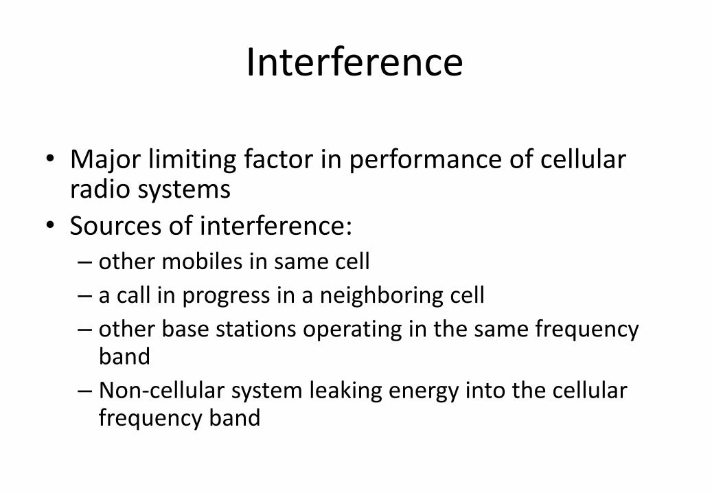
• Major limiting factor in performance of cellular radio systems
• Sources of interference: – other mobiles in same cell
– a call in progress in a neighboring cell
– other base stations operating in the same frequency band
– Non-cellular system leaking energy into the cellular frequency band
Interference
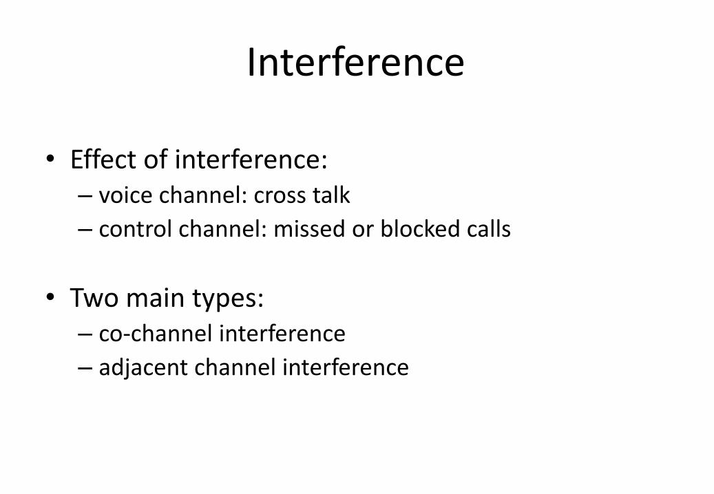
• Effect of interference: – voice channel: cross talk
– control channel: missed or blocked calls
• Two main types: – co-channel interference
– adjacent channel interference
Co-Channel Interference
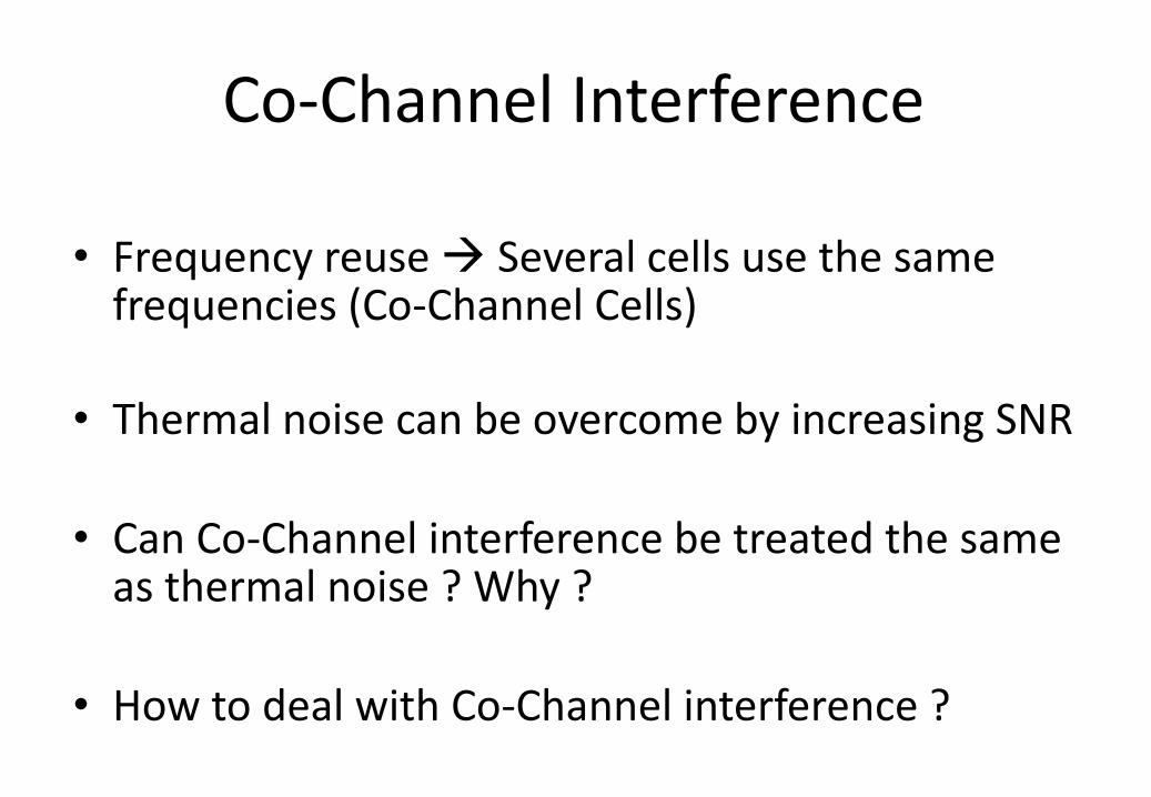
• Frequency reuse Several cells use the same frequencies (Co-Channel Cells)
• Thermal noise can be overcome by increasing SNR
• Can Co-Channel interference be treated the same as thermal noise ? Why ?
• How to deal with Co-Channel interference ?
Co-Channel Interference
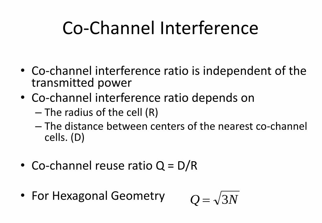
• Co-channel interference ratio is independent of the transmitted power
• Co-channel interference ratio depends on – The radius of the cell (R) – The distance between centers of the nearest co-channel
cells. (D)
• Co-channel reuse ratio Q = D/R
• For Hexagonal Geometry NQ 3
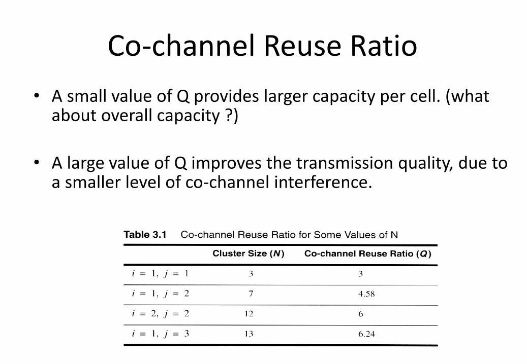
Co-channel Reuse Ratio
• A small value of Q provides larger capacity per cell. (what about overall capacity ?)
• A large value of Q improves the transmission quality, due to a smaller level of co-channel interference.
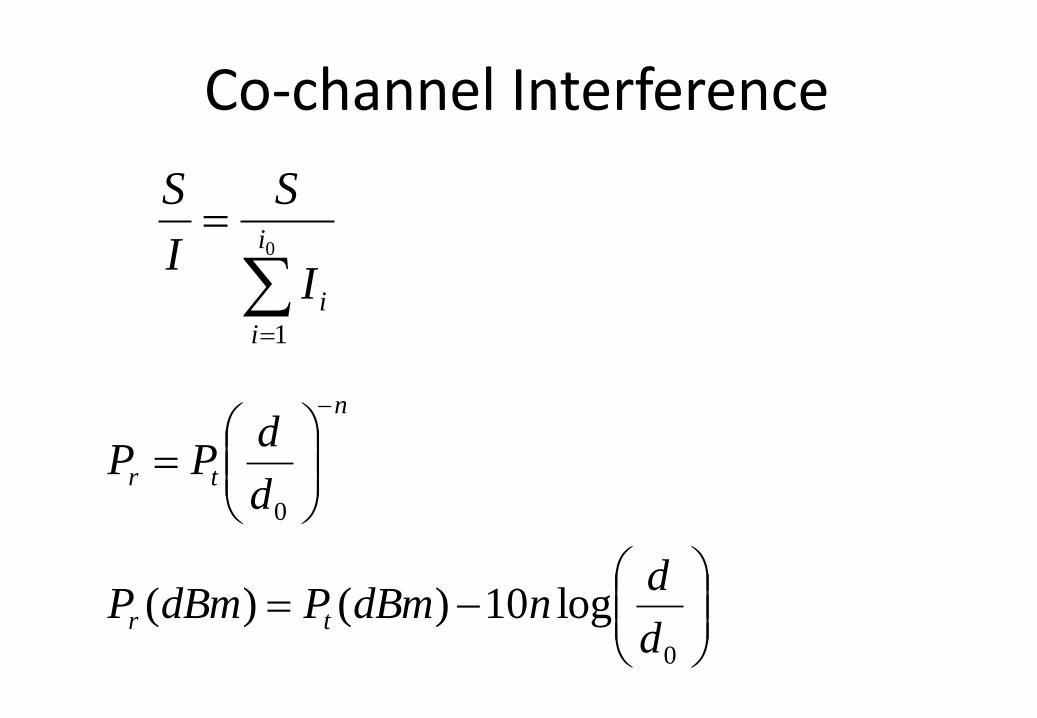
Co-channel Interference
0
1
i
i
iI
S
I
S
0
0
log10)()(d
dndBmPdBmP
d
dPP
tr
n
tr
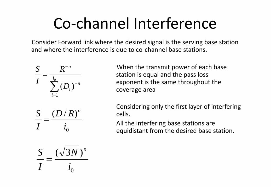
Co-channel Interference Consider Forward link where the desired signal is the serving base station and where the interference is due to co-channel base stations.
0
1
)(i
i
n
i
n
D
R
I
S
0
)/(
i
RD
I
S n
0
)3(
i
N
I
S n
When the transmit power of each base station is equal and the pass loss exponent is the same throughout the coverage area
Considering only the first layer of interfering cells.
All the interfering base stations are equidistant from the desired base station.
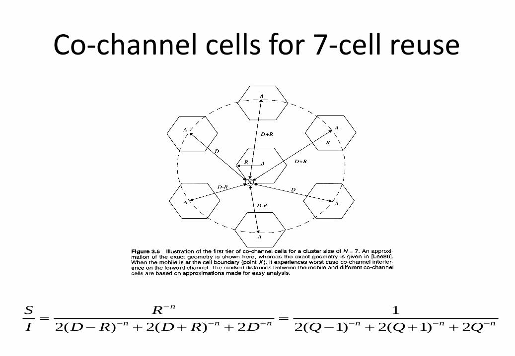
Co-channel cells for 7-cell reuse
nnnnnn
n
QQQDRDRD
R
I
S
2)1(2)1(2
1
2)(2)(2
Example
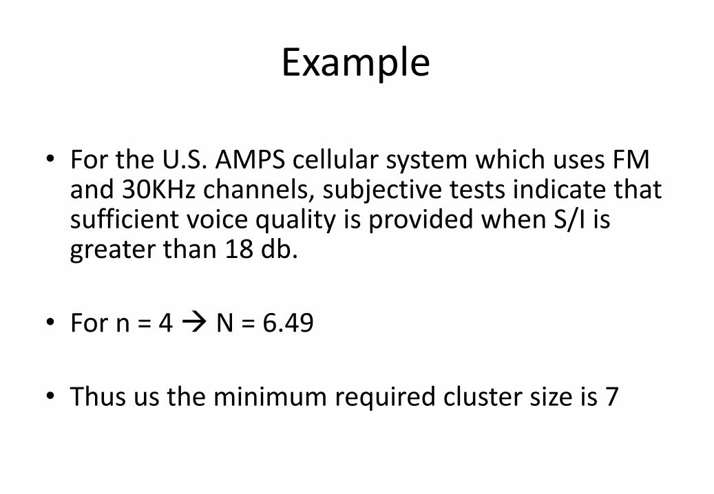
• For the U.S. AMPS cellular system which uses FM and 30KHz channels, subjective tests indicate that sufficient voice quality is provided when S/I is greater than 18 db.
• For n = 4 N = 6.49
• Thus us the minimum required cluster size is 7
Example
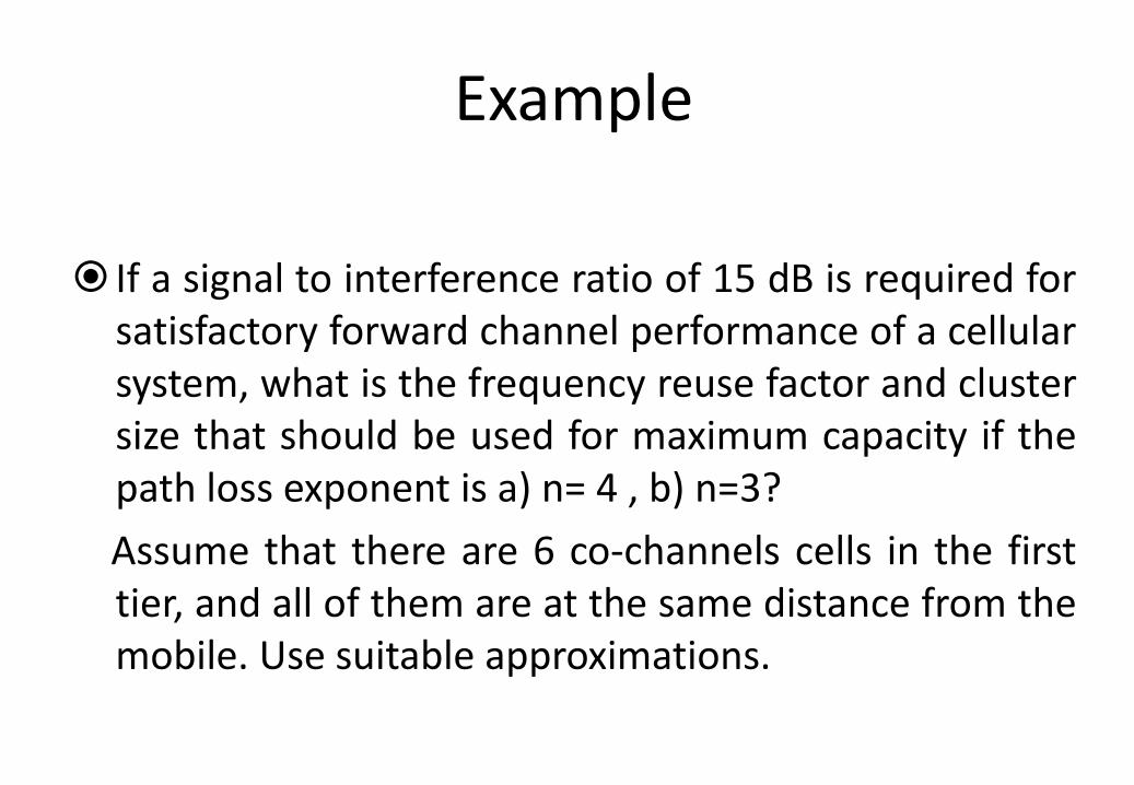
If a signal to interference ratio of 15 dB is required for satisfactory forward channel performance of a cellular system, what is the frequency reuse factor and cluster size that should be used for maximum capacity if the path loss exponent is a) n= 4 , b) n=3?
Assume that there are 6 co-channels cells in the first tier, and all of them are at the same distance from the mobile. Use suitable approximations.
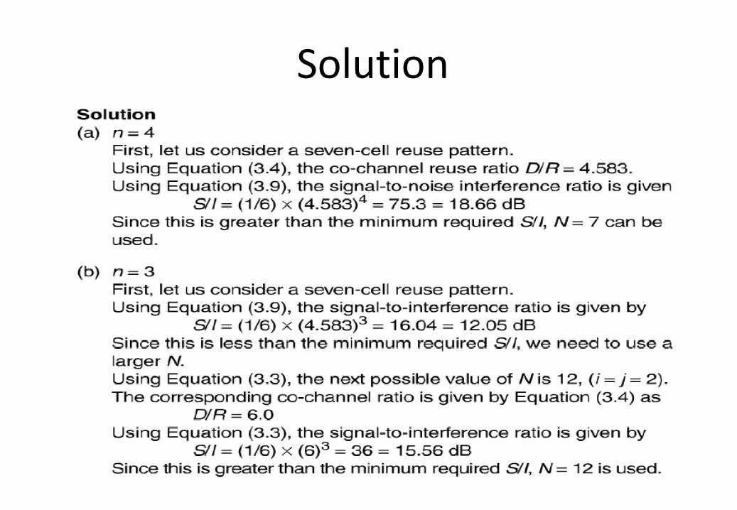
Solution
Adjacent Channel Interference • Adjacent channel interference is the interference resulting
from signals which are adjacent in frequency to the desired signal.
• It results from imperfect receiver filters which allow nearby frequencies to leak into the passband.
• Near-Far effect .
• By keeping the frequency separation between each in a given cell as large as possible the adjacent channel interference is reduced
Example
Example
Example
Trunking Theory
• The concept of trunking allows a large number of users to share the relatively small number of channels in a cell by providing access to each user, on demand, from a pool of available channels.
• Tradeoff between the number of channels and blocking probability
• Grade of service
– Likelihood of a call is blocked or the delay greater than a threshold during the busiest time.
• Trunking Theory
– Erlang, a Danish Mathematician studied how a large population could be accommodated by a limited number of servers.
– Erlang capacity: the amount of traffic intensity carried by a channel.
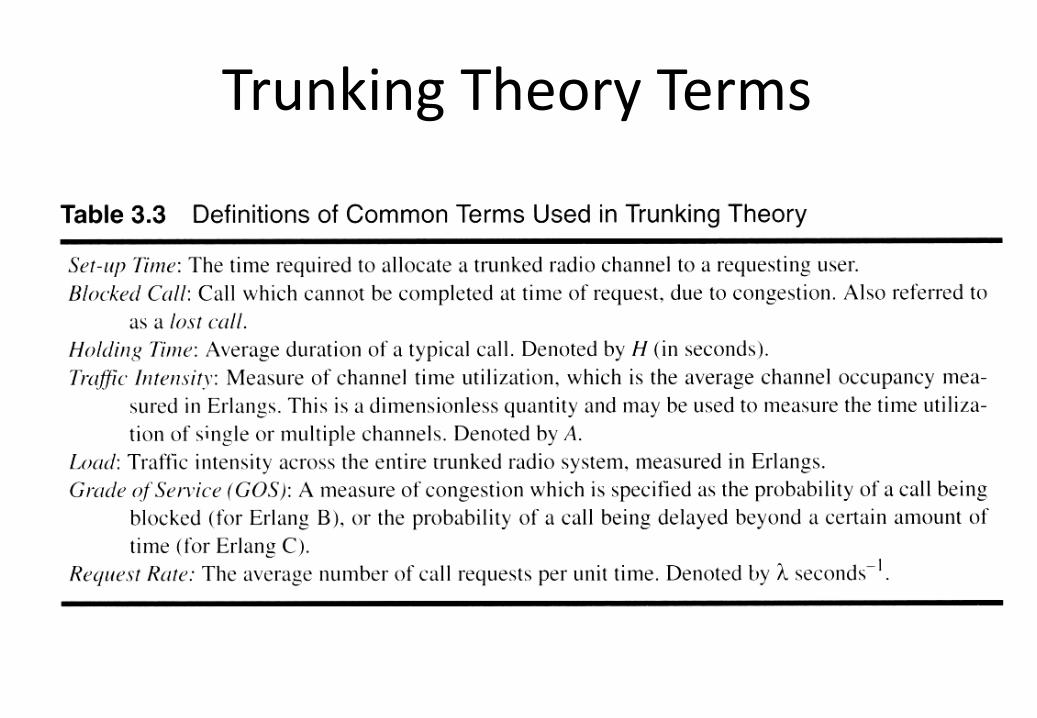
Trunking Theory Terms
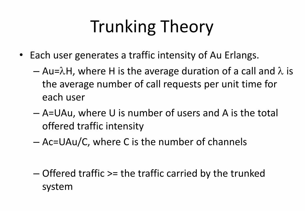
Trunking Theory
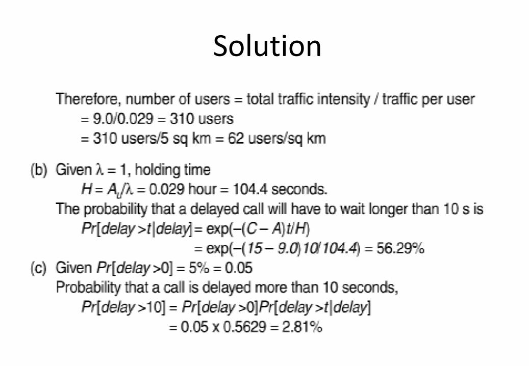
• Each user generates a traffic intensity of Au Erlangs.
– Au=H, where H is the average duration of a call and is the average number of call requests per unit time for each user
– A=UAu, where U is number of users and A is the total offered traffic intensity
– Ac=UAu/C, where C is the number of channels
– Offered traffic >= the traffic carried by the trunked system
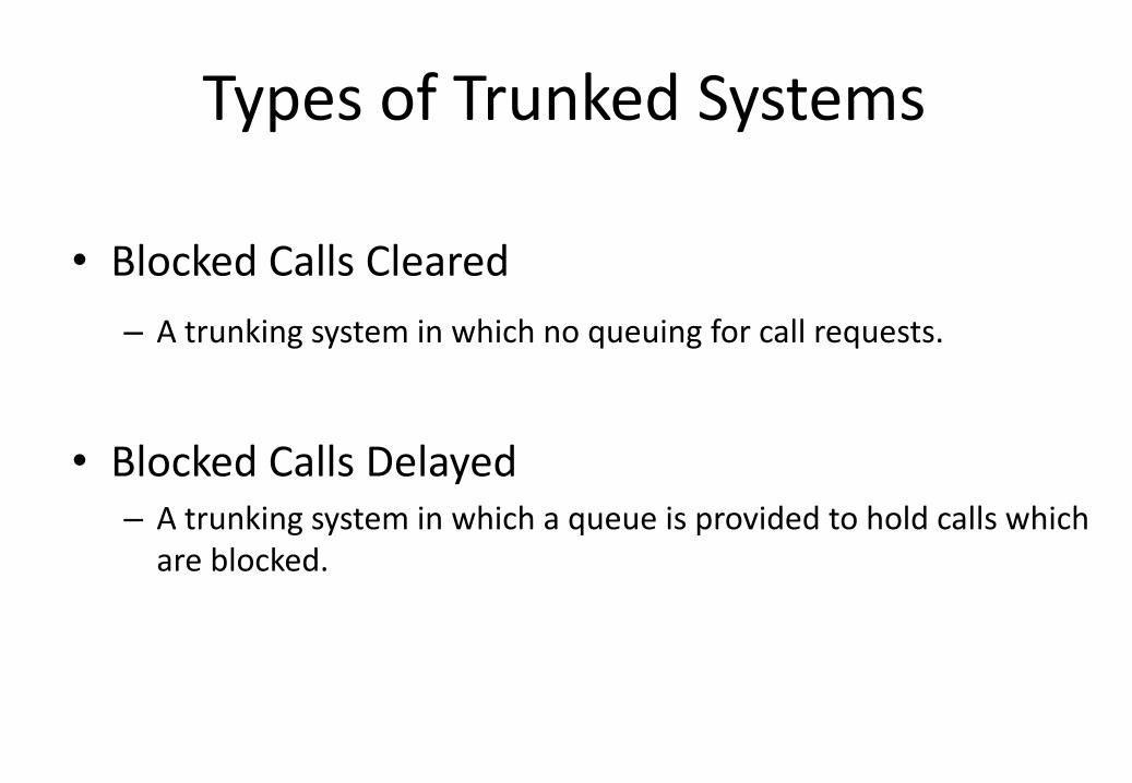
Types of Trunked Systems
• Blocked Calls Cleared
– A trunking system in which no queuing for call requests.
• Blocked Calls Delayed – A trunking system in which a queue is provided to hold calls which
are blocked.
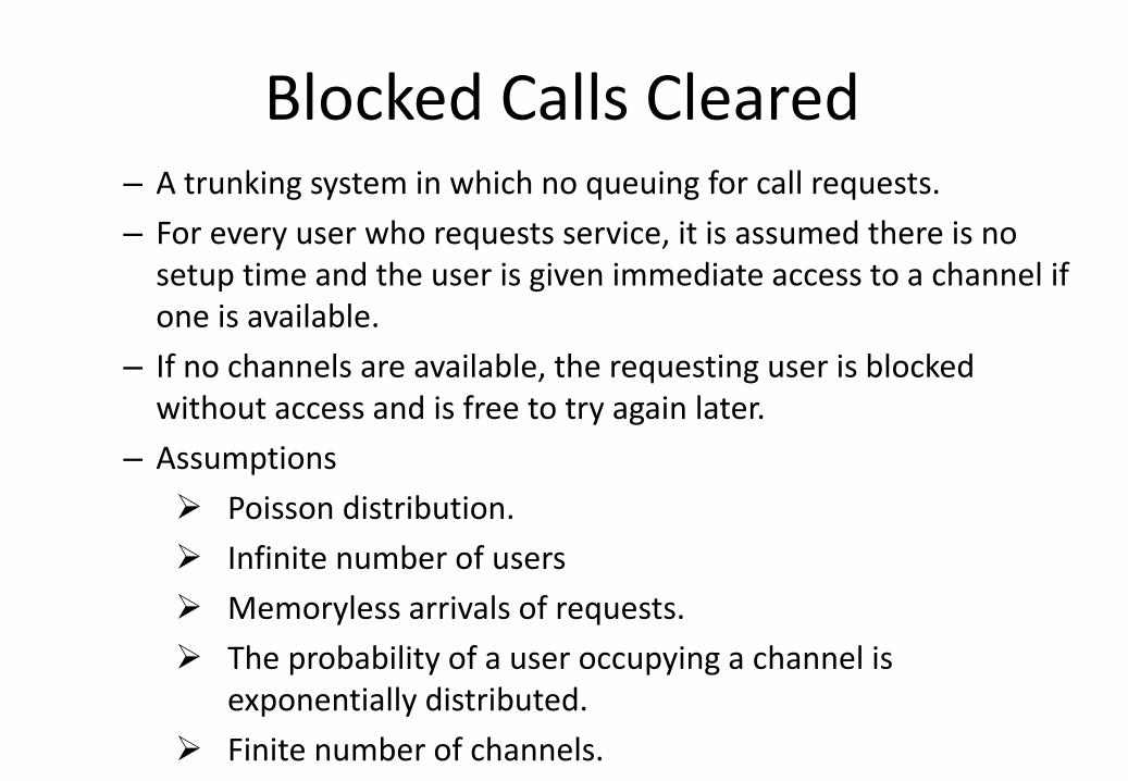
Blocked Calls Cleared – A trunking system in which no queuing for call requests.
– For every user who requests service, it is assumed there is no setup time and the user is given immediate access to a channel if one is available.
– If no channels are available, the requesting user is blocked without access and is free to try again later.
– Assumptions
Poisson distribution.
Infinite number of users
Memoryless arrivals of requests.
The probability of a user occupying a channel is exponentially distributed.
Finite number of channels.
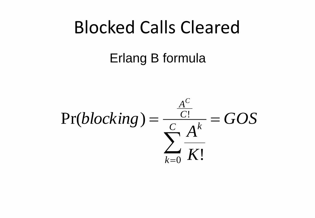
Blocked Calls Cleared
Erlang B formula
GOS
K
Ablocking
C
k
k
CAC
0
!
!
)Pr(
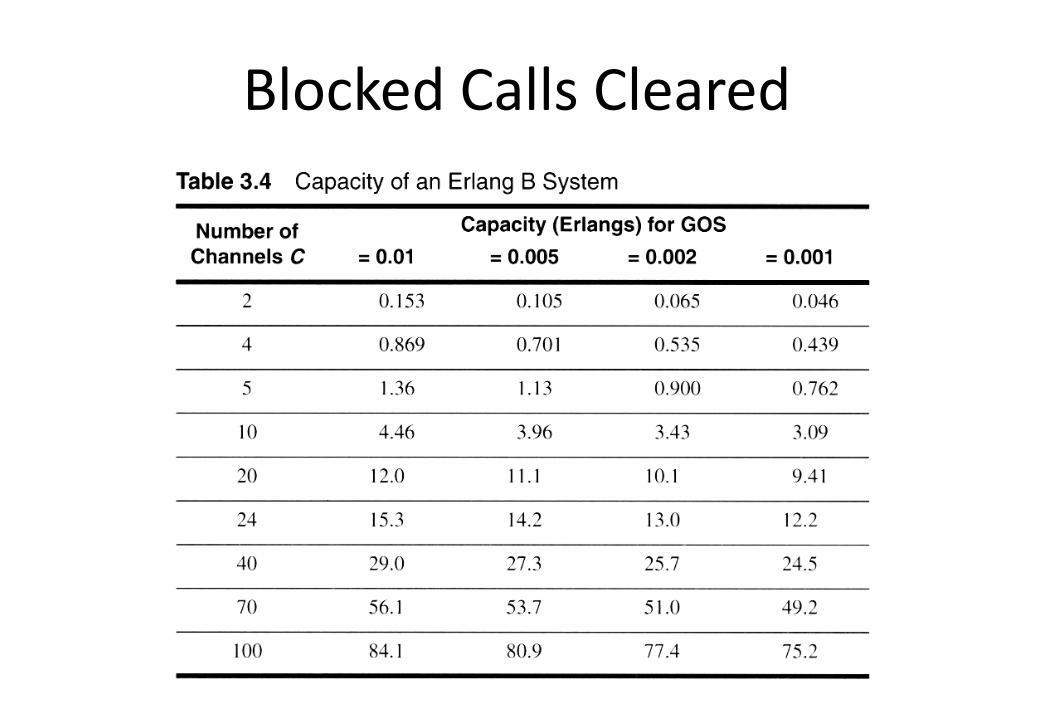
Blocked Calls Cleared
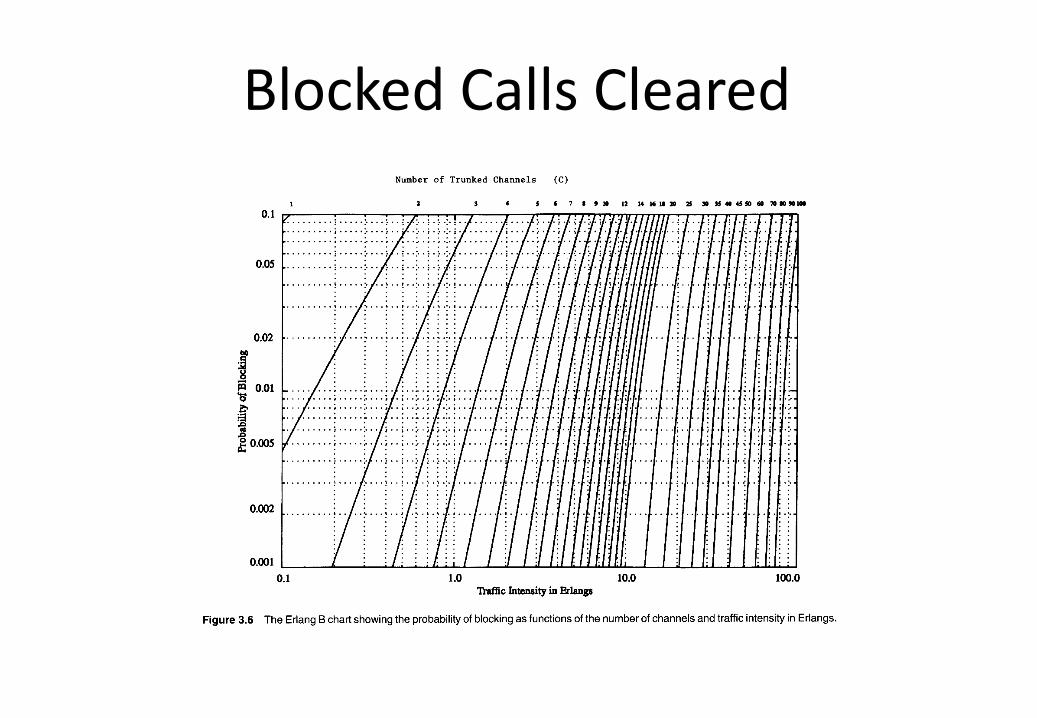
Blocked Calls Cleared
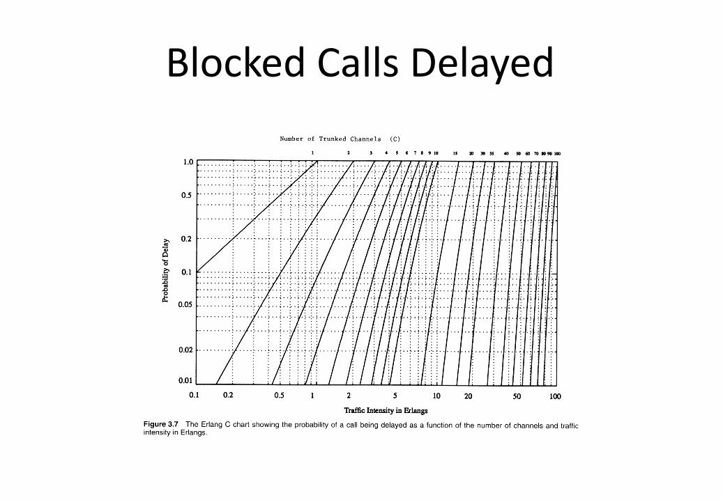
Blocked Calls Delayed
– A trunking system in which a queue is provided to hold calls which are blocked.
– If a channel is not available immediately, the call request may be delayed until a channel becomes available.
– The measure of GOS is defined as the probability that a call is blocked after waiting a specific length of time in the queue.
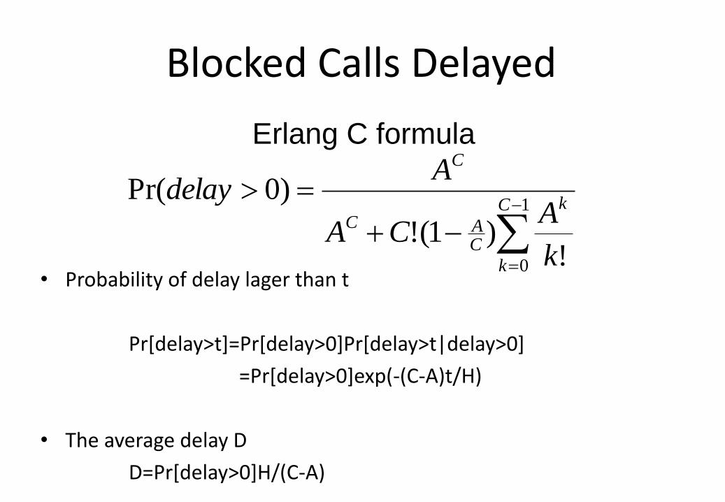
Blocked Calls Delayed
• Probability of delay lager than t
Pr[delay>t]=Pr[delay>0]Pr[delay>t|delay>0]
=Pr[delay>0]exp(-(C-A)t/H)
• The average delay D
D=Pr[delay>0]H/(C-A)
Erlang C formula
1
0 !)1(!
)0Pr(C
k
k
CAC
C
k
ACA
Adelay
Blocked Calls Delayed
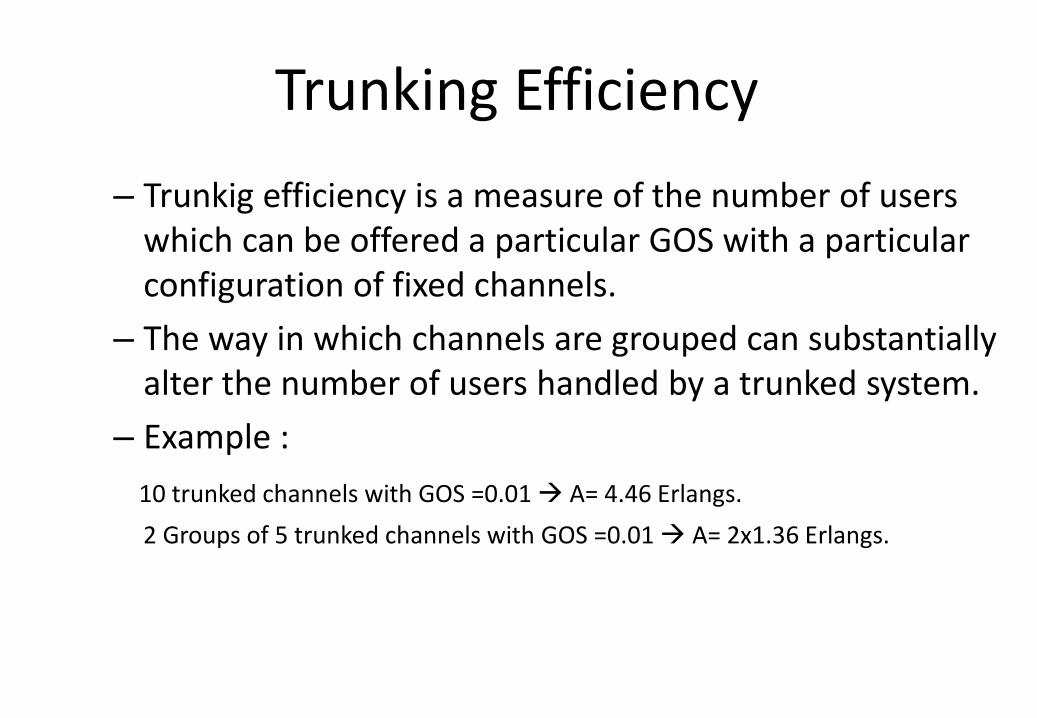
Trunking Efficiency
– Trunkig efficiency is a measure of the number of users which can be offered a particular GOS with a particular configuration of fixed channels.
– The way in which channels are grouped can substantially alter the number of users handled by a trunked system.
– Example :
10 trunked channels with GOS =0.01 A= 4.46 Erlangs.
2 Groups of 5 trunked channels with GOS =0.01 A= 2x1.36 Erlangs.
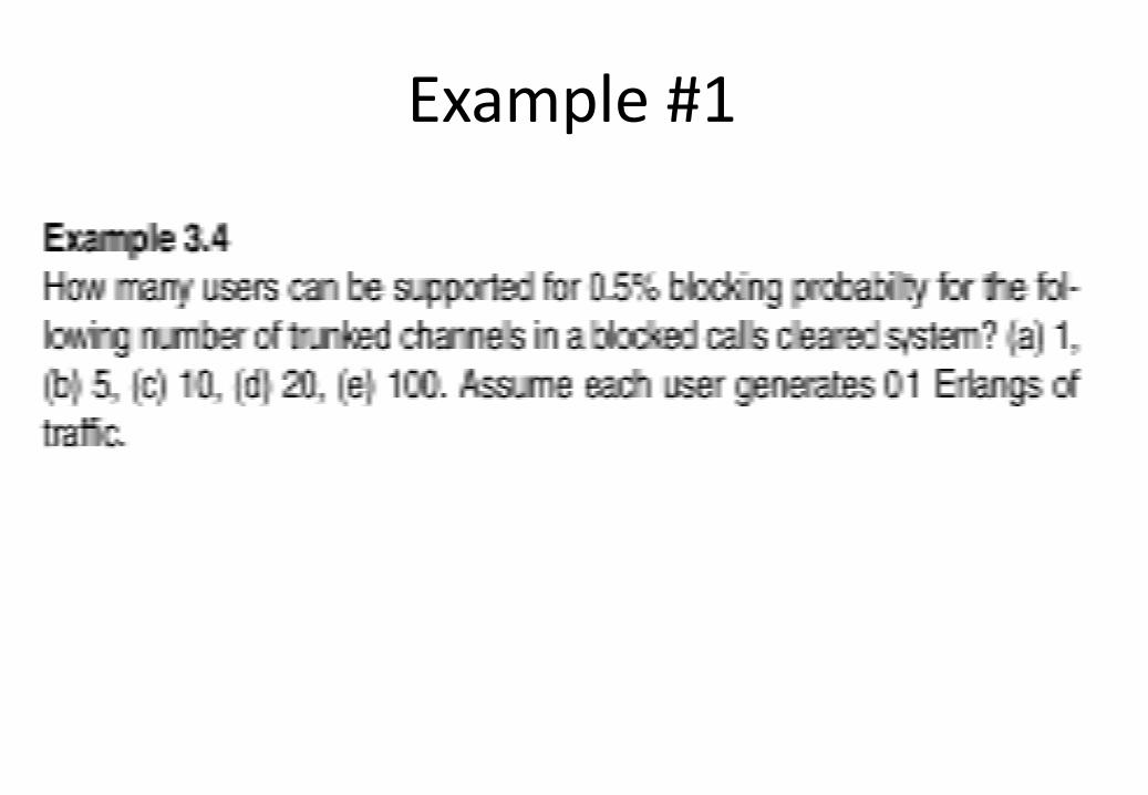
Example #1
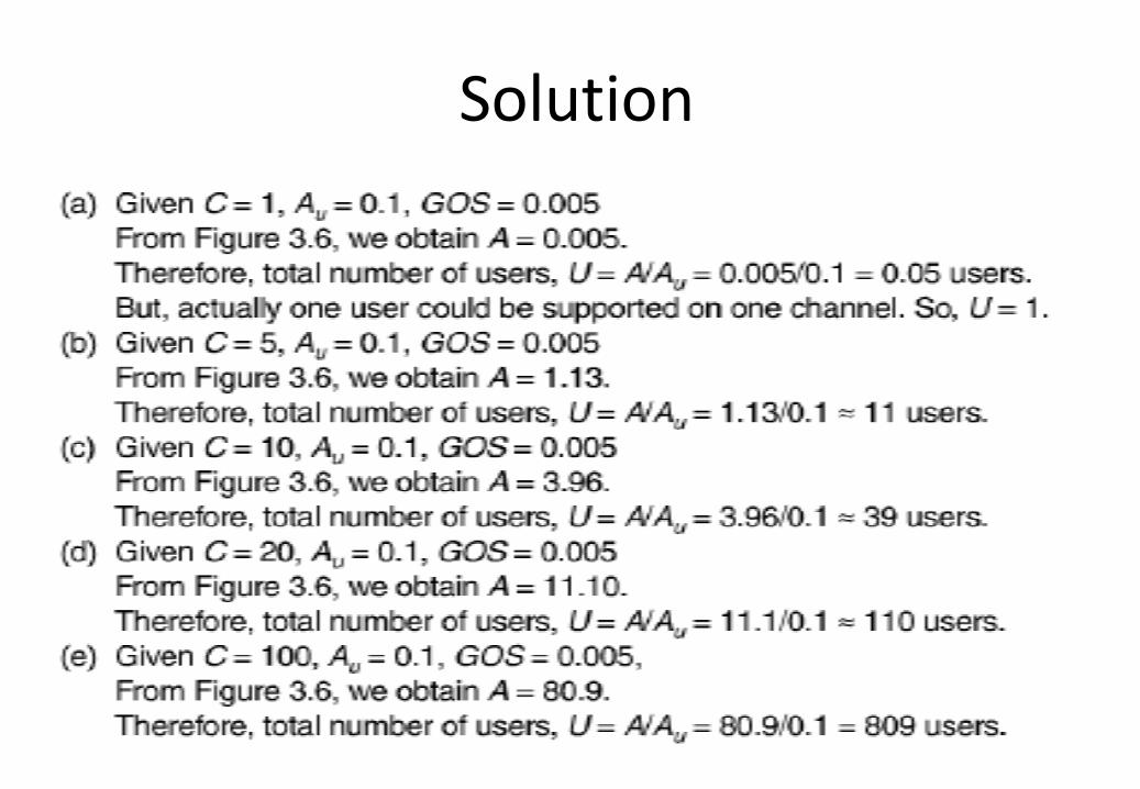
Solution
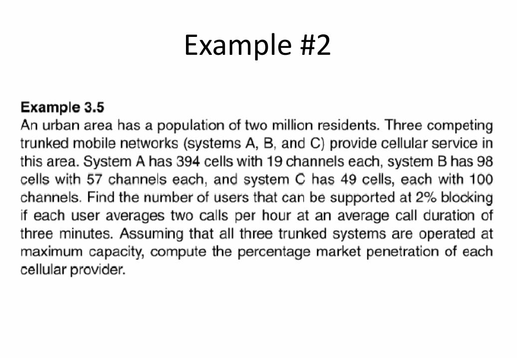
Example #2
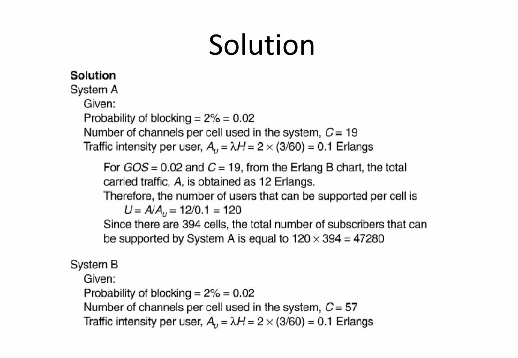
Solution
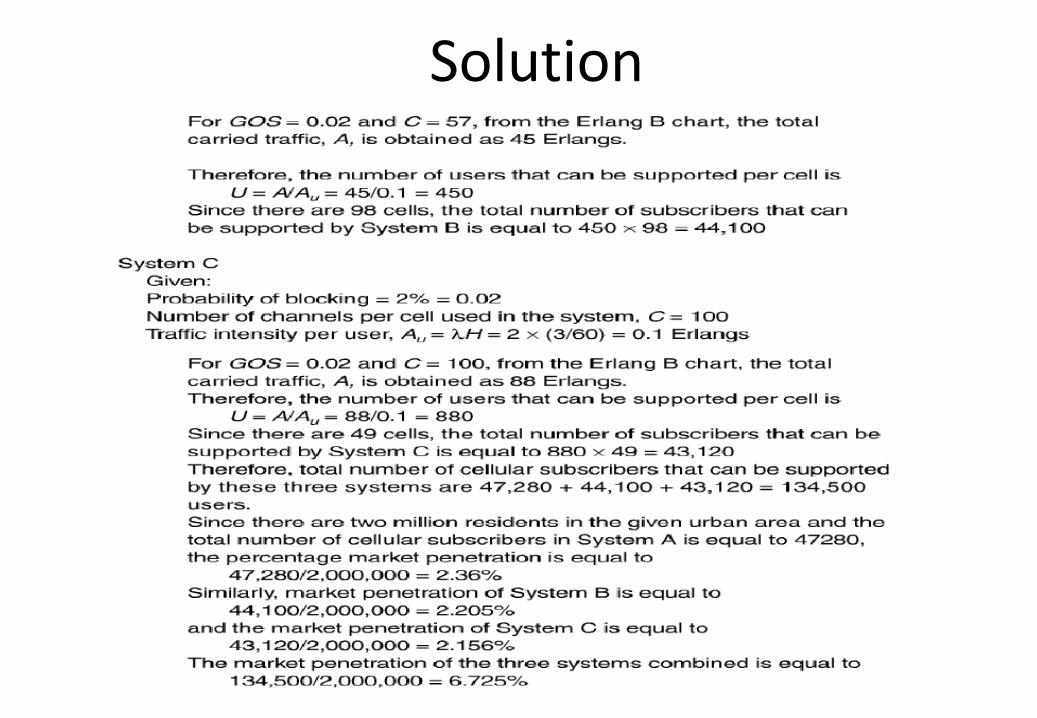
Solution
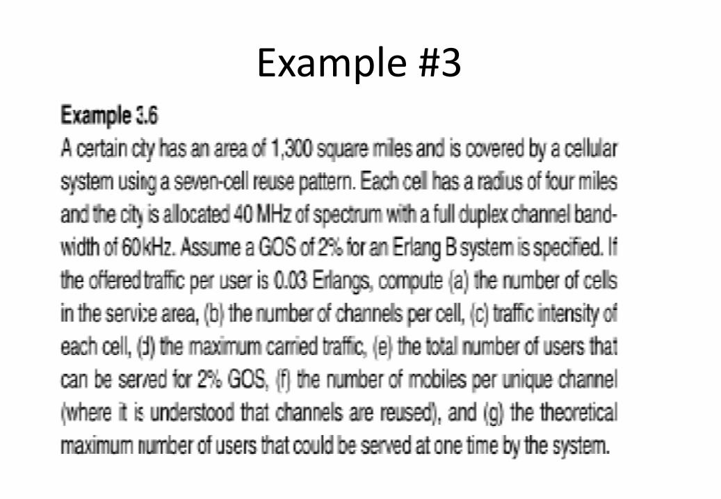
Example #3
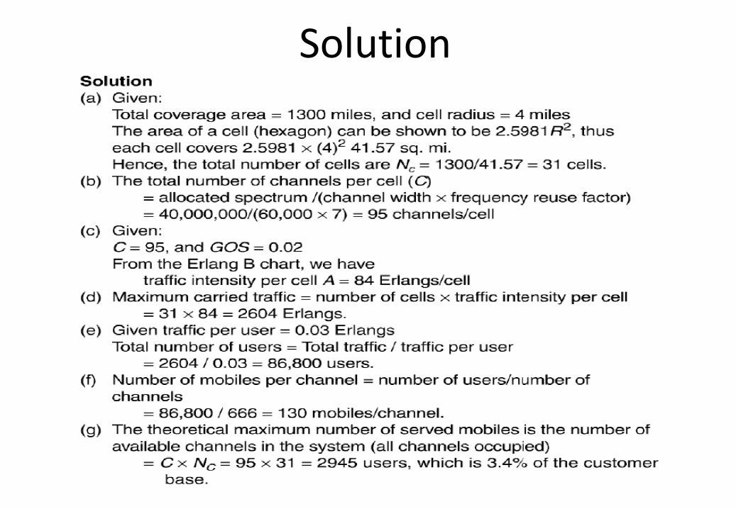
Solution
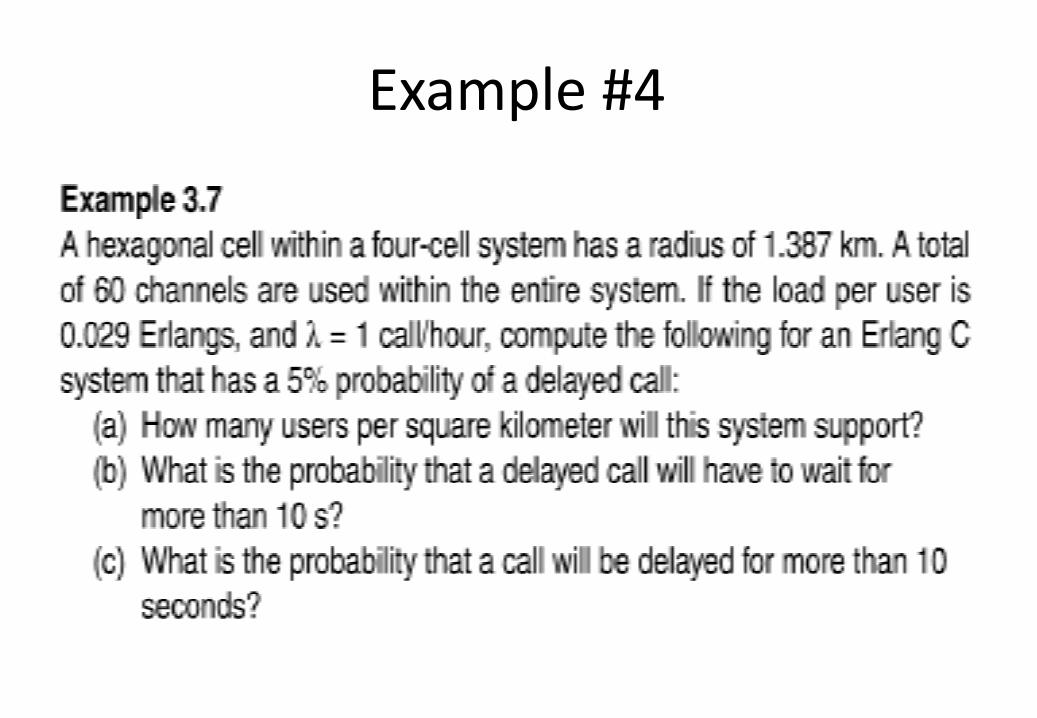
Example #4
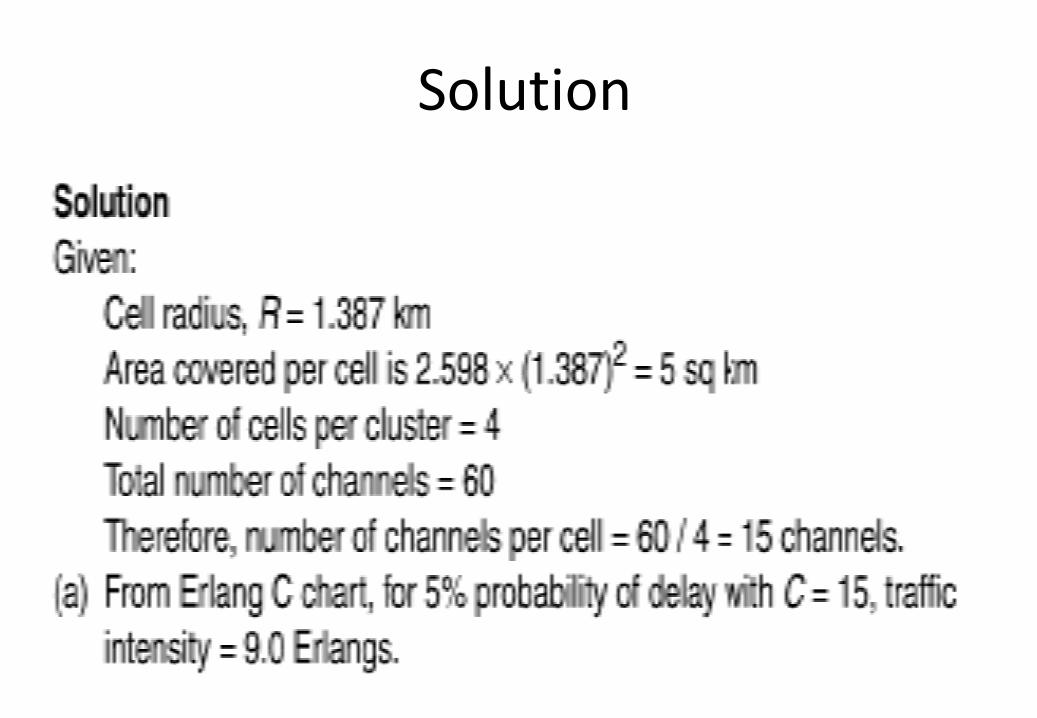
Solution
Solution
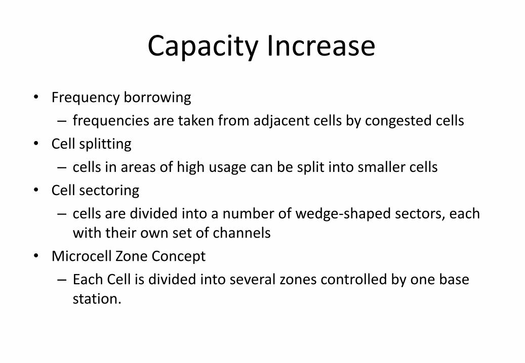
Capacity Increase
• Frequency borrowing
– frequencies are taken from adjacent cells by congested cells
• Cell splitting
– cells in areas of high usage can be split into smaller cells
• Cell sectoring
– cells are divided into a number of wedge-shaped sectors, each with their own set of channels
• Microcell Zone Concept
– Each Cell is divided into several zones controlled by one base station.
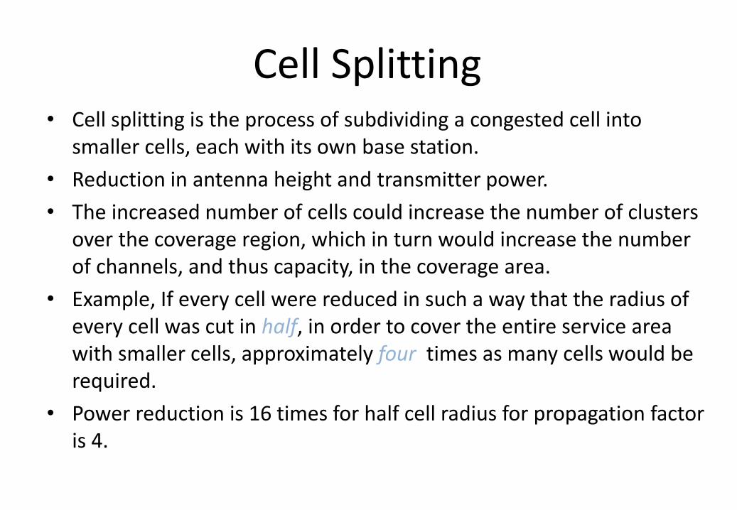
Cell Splitting • Cell splitting is the process of subdividing a congested cell into
smaller cells, each with its own base station.
• Reduction in antenna height and transmitter power.
• The increased number of cells could increase the number of clusters over the coverage region, which in turn would increase the number of channels, and thus capacity, in the coverage area.
• Example, If every cell were reduced in such a way that the radius of every cell was cut in half, in order to cover the entire service area with smaller cells, approximately four times as many cells would be required.
• Power reduction is 16 times for half cell radius for propagation factor is 4.
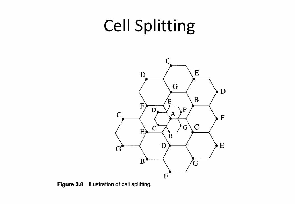
Cell Splitting
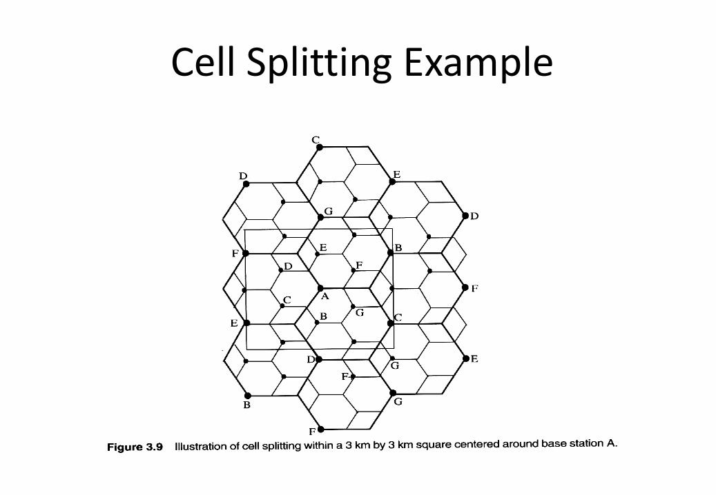
Cell Splitting Example
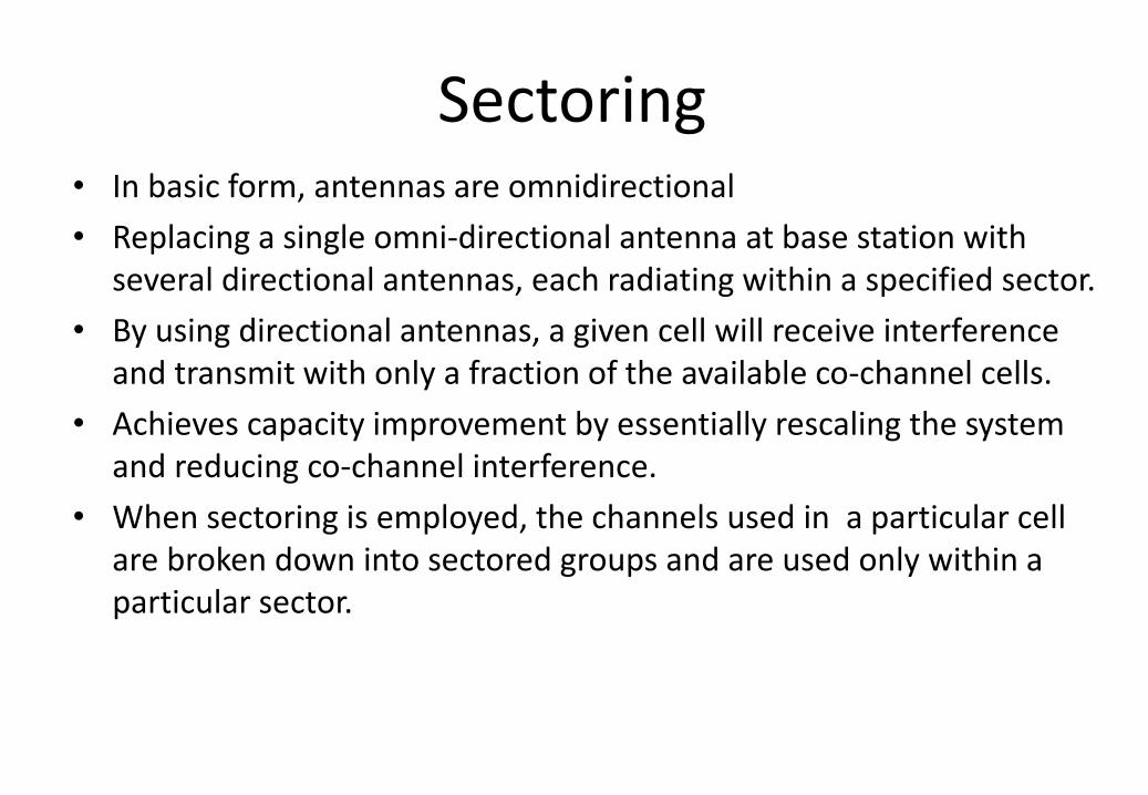
Sectoring • In basic form, antennas are omnidirectional
• Replacing a single omni-directional antenna at base station with several directional antennas, each radiating within a specified sector.
• By using directional antennas, a given cell will receive interference and transmit with only a fraction of the available co-channel cells.
• Achieves capacity improvement by essentially rescaling the system and reducing co-channel interference.
• When sectoring is employed, the channels used in a particular cell are broken down into sectored groups and are used only within a particular sector.
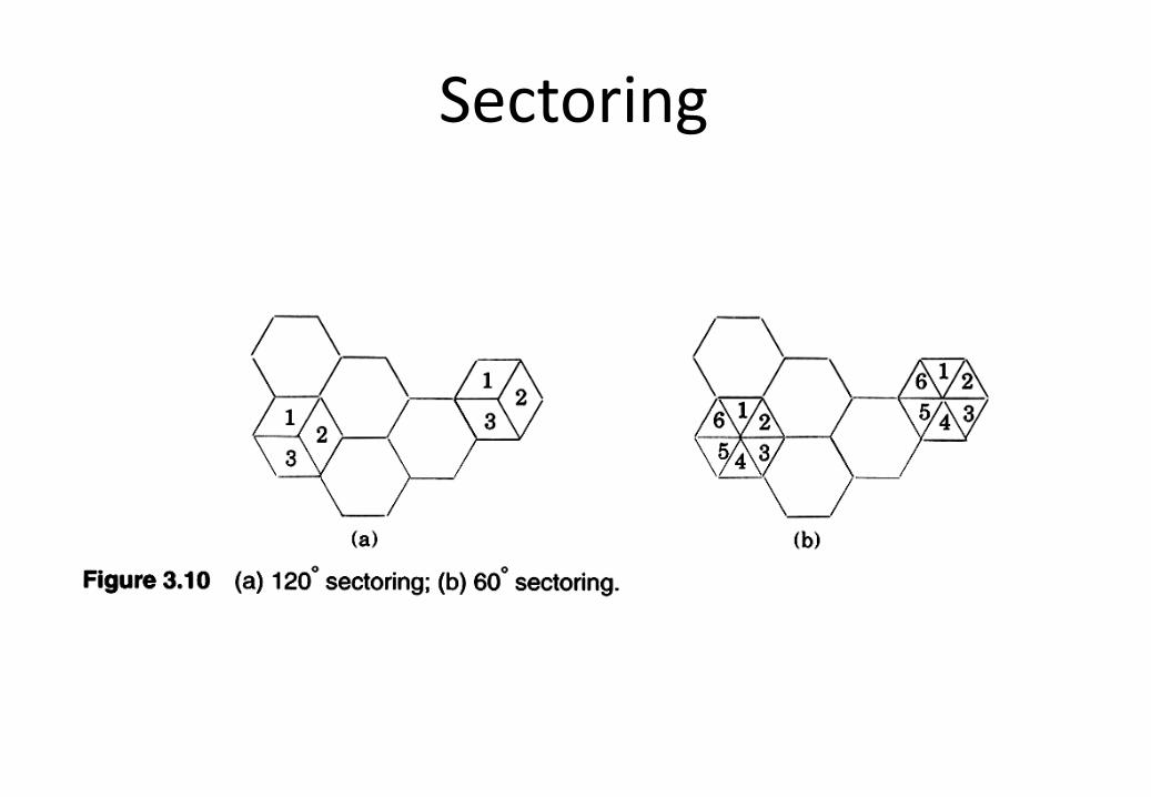
Sectoring
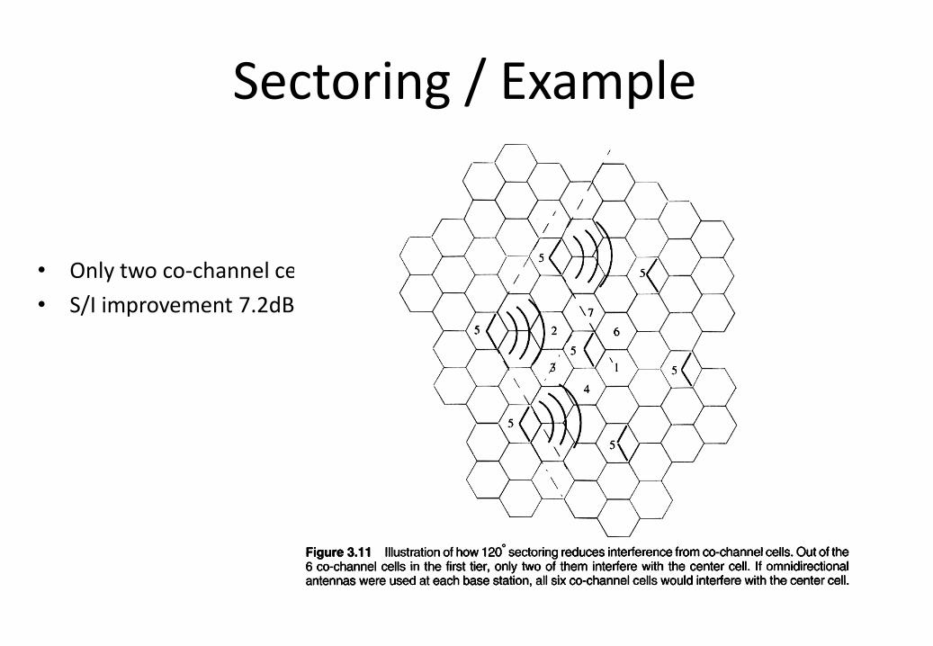
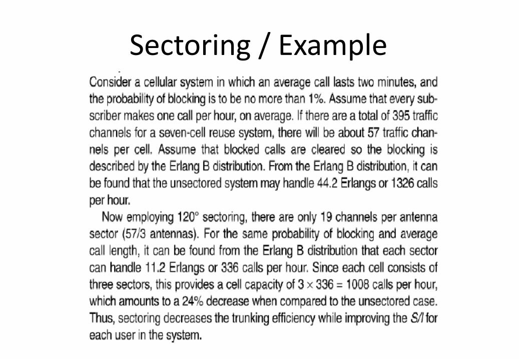
Sectoring / Example
• Only two co-channel cell
• S/I improvement 7.2dB
Sectoring Disadvantages
• Increased number of antennas at each base station.
• Decreasing Trunking Efficiency.
• Increasing Handoffs
• Not good in Dense Urban Areas
Sectoring / Example
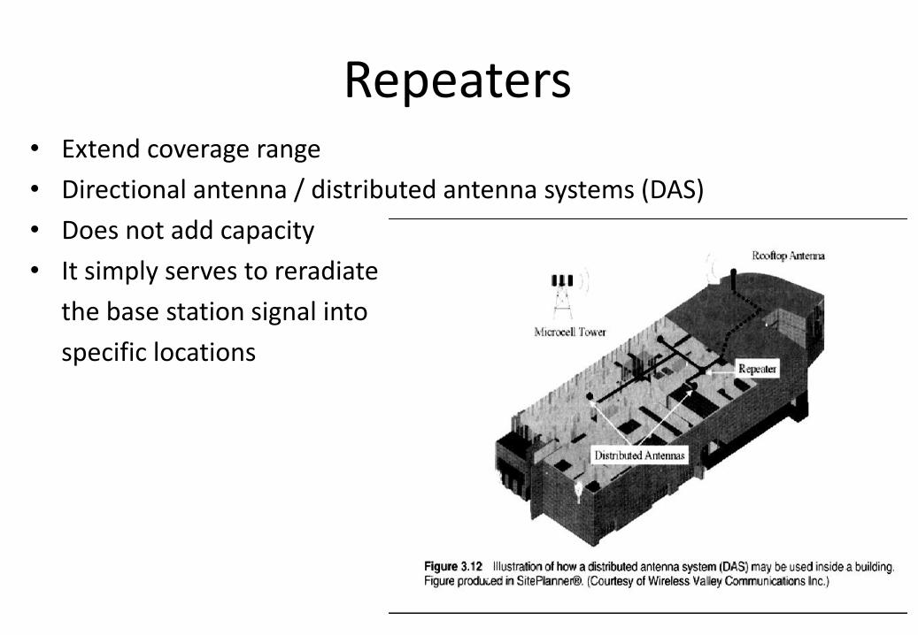
Repeaters • Extend coverage range
• Directional antenna / distributed antenna systems (DAS)
• Does not add capacity
• It simply serves to reradiate
the base station signal into
specific locations
Micro Cell Zone
• Large control base station is replaced by several lower powered transmitters on the edge of the cell.
• The mobile retains the same channel and the base station simply switches the channel to a different zone site and the mobile moves from zone to zone.
• Superior to sectoring, any base station channel may be assigned to any zone by the base station
• No handoffs between zones in the same cell
• Since a given channel is active only in a particular zone in which mobile is traveling, base station radiation is localized and interference is reduced.
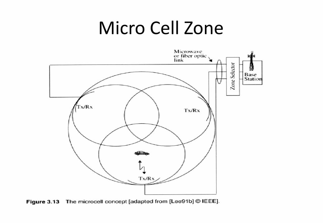
Micro Cell Zone
The End of Chapter 3