Embed Size (px)
Citation preview
3–1
N
36 E 12
15S
2124W31
33
–20
–15
–10
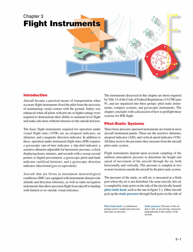
Chapter 3
Flight Instruments
IntroductionAircraft became a practical means of transportation whenaccurate flight instruments freed the pilot from the necessityof maintaining visual contact with the ground. Safety wasenhanced when all pilots with private or higher ratings wererequired to demonstrate their ability to maintain level flightand make safe turns without reference to the outside horizon.
The basic flight instruments required for operation undervisual flight rules (VFR) are an airspeed indicator, analtimeter, and a magnetic direction indicator. In addition tothese, operation under instrument flight rules (IFR) requiresa gyroscopic rate-of-turn indicator, a slip-skid indicator, asensitive altimeter adjustable for barometric pressure, a clockdisplaying hours, minutes, and seconds with a sweep-secondpointer or digital presentation, a gyroscopic pitch-and-bankindicator (artificial horizon), and a gyroscopic directionindicator (directional gyro or equivalent).
Aircraft that are flown in instrument meteorologicalconditions (IMC) are equipped with instruments that provideattitude and direction reference, as well as radio navigationinstruments that allow precision flight from takeoff to landingwith limited or no outside visual reference.
The instruments discussed in this chapter are those requiredby Title 14 of the Code of Federal Regulations (14 CFR) part91, and are organized into three groups: pitot-static instru-ments, compass systems, and gyroscopic instruments. Thechapter concludes with a discussion of how to preflight thesesystems for IFR flight.
Pitot-Static SystemsThree basic pressure-operated instruments are found in mostaircraft instrument panels. These are the sensitive altimeter,airspeed indicator (ASI), and vertical speed indicator (VSI).All three receive the pressures they measure from the aircraftpitot-static system.
Flight instruments depend upon accurate sampling of theambient atmospheric pressure to determine the height andspeed of movement of the aircraft through the air, bothhorizontally and vertically. This pressure is sampled at twoor more locations outside the aircraft by the pitot-static system.
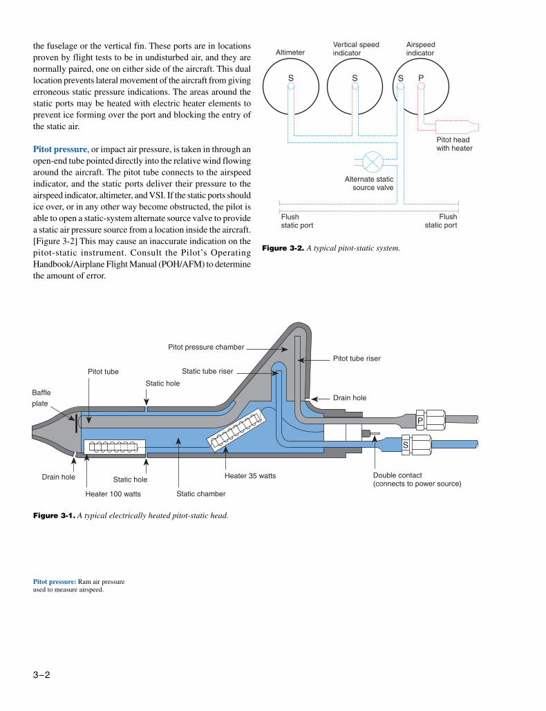
The pressure of the static, or still air, is measured at a flushport where the air is not disturbed. On some aircraft, this airis sampled by static ports on the side of the electrically heatedpitot-static head, such as the one in figure 3-1. Other aircraftpick up the static pressure through flush ports on the side of
Pitot-static head: A combinationpickup used to sample pitot pressureand static air pressure.
Static pressure: Pressure of the airthat is still, or not moving, measuredperpendicular to the surface of theaircraft.
3–2
Figure 3-1. A typical electrically heated pitot-static head.
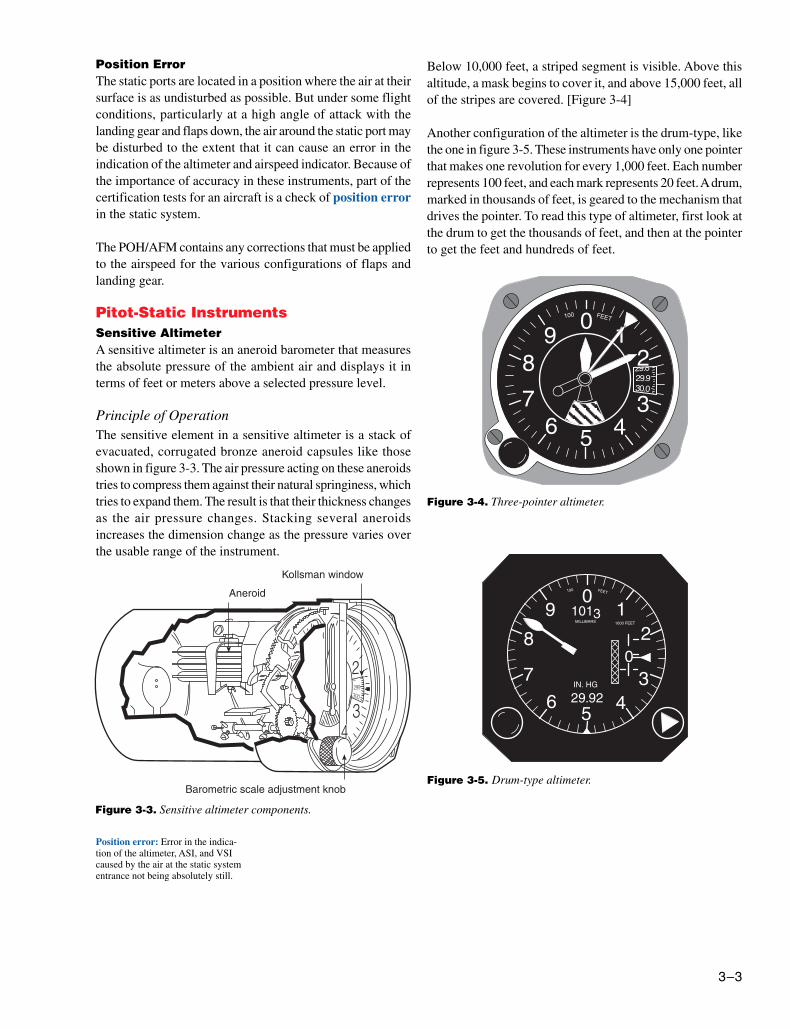
Figure 3-2. A typical pitot-static system.
Pitot pressure: Ram air pressureused to measure airspeed.
the fuselage or the vertical fin. These ports are in locationsproven by flight tests to be in undisturbed air, and they arenormally paired, one on either side of the aircraft. This duallocation prevents lateral movement of the aircraft from givingerroneous static pressure indications. The areas around thestatic ports may be heated with electric heater elements toprevent ice forming over the port and blocking the entry ofthe static air.
Pitot pressure, or impact air pressure, is taken in through anopen-end tube pointed directly into the relative wind flowingaround the aircraft. The pitot tube connects to the airspeedindicator, and the static ports deliver their pressure to theairspeed indicator, altimeter, and VSI. If the static ports shouldice over, or in any other way become obstructed, the pilot isable to open a static-system alternate source valve to providea static air pressure source from a location inside the aircraft.[Figure 3-2] This may cause an inaccurate indication on thepitot-static instrument. Consult the Pilot’s OperatingHandbook/Airplane Flight Manual (POH/AFM) to determinethe amount of error.
3–3
Position error: Error in the indica-tion of the altimeter, ASI, and VSIcaused by the air at the static systementrance not being absolutely still.
Figure 3-4. Three-pointer altimeter.
Figure 3-5. Drum-type altimeter.
Position ErrorThe static ports are located in a position where the air at theirsurface is as undisturbed as possible. But under some flightconditions, particularly at a high angle of attack with thelanding gear and flaps down, the air around the static port maybe disturbed to the extent that it can cause an error in theindication of the altimeter and airspeed indicator. Because ofthe importance of accuracy in these instruments, part of thecertification tests for an aircraft is a check of position errorin the static system.
The POH/AFM contains any corrections that must be appliedto the airspeed for the various configurations of flaps andlanding gear.
Pitot-Static InstrumentsSensitive AltimeterA sensitive altimeter is an aneroid barometer that measuresthe absolute pressure of the ambient air and displays it interms of feet or meters above a selected pressure level.
Principle of OperationThe sensitive element in a sensitive altimeter is a stack ofevacuated, corrugated bronze aneroid capsules like thoseshown in figure 3-3. The air pressure acting on these aneroidstries to compress them against their natural springiness, whichtries to expand them. The result is that their thickness changesas the air pressure changes. Stacking several aneroidsincreases the dimension change as the pressure varies overthe usable range of the instrument.
Below 10,000 feet, a striped segment is visible. Above thisaltitude, a mask begins to cover it, and above 15,000 feet, allof the stripes are covered. [Figure 3-4]
Another configuration of the altimeter is the drum-type, likethe one in figure 3-5. These instruments have only one pointerthat makes one revolution for every 1,000 feet. Each numberrepresents 100 feet, and each mark represents 20 feet. A drum,marked in thousands of feet, is geared to the mechanism thatdrives the pointer. To read this type of altimeter, first look atthe drum to get the thousands of feet, and then at the pointerto get the feet and hundreds of feet.
Figure 3-3. Sensitive altimeter components.
3–4
Kollsman window: A barometricscale window of a sensitive altimeter.
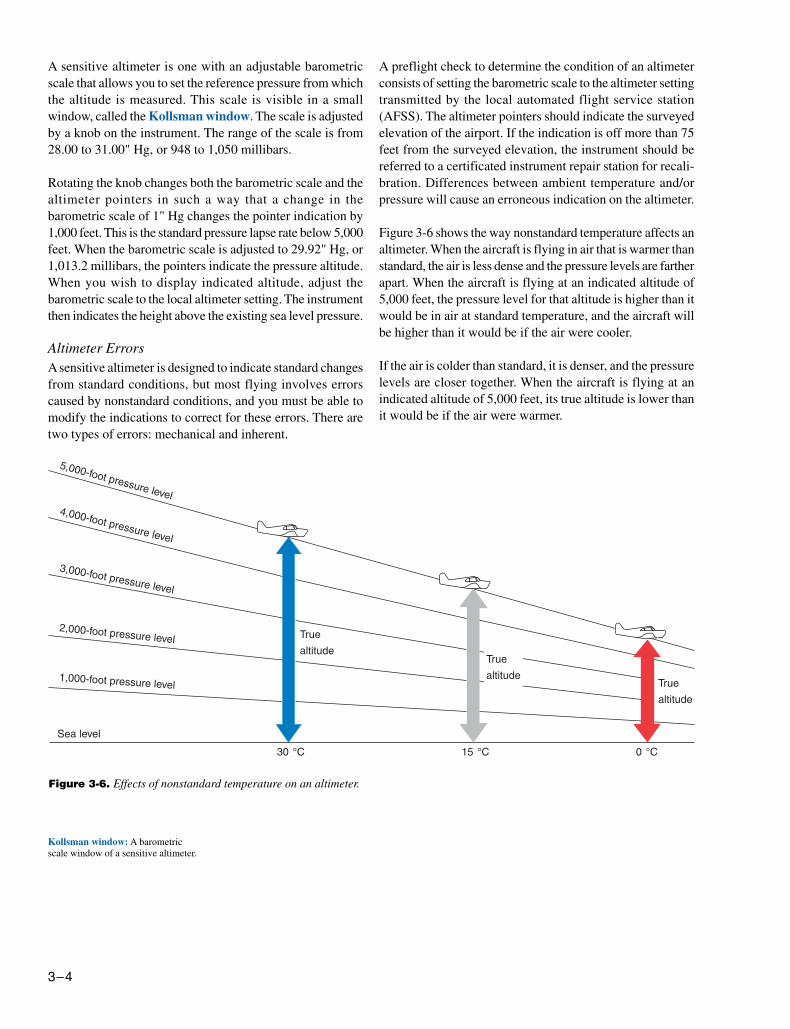
Figure 3-6. Effects of nonstandard temperature on an altimeter.
A sensitive altimeter is one with an adjustable barometricscale that allows you to set the reference pressure from whichthe altitude is measured. This scale is visible in a smallwindow, called the Kollsman window. The scale is adjustedby a knob on the instrument. The range of the scale is from28.00 to 31.00" Hg, or 948 to 1,050 millibars.
Rotating the knob changes both the barometric scale and thealtimeter pointers in such a way that a change in thebarometric scale of 1" Hg changes the pointer indication by1,000 feet. This is the standard pressure lapse rate below 5,000feet. When the barometric scale is adjusted to 29.92" Hg, or1,013.2 millibars, the pointers indicate the pressure altitude.When you wish to display indicated altitude, adjust thebarometric scale to the local altimeter setting. The instrumentthen indicates the height above the existing sea level pressure.
Altimeter ErrorsA sensitive altimeter is designed to indicate standard changesfrom standard conditions, but most flying involves errorscaused by nonstandard conditions, and you must be able tomodify the indications to correct for these errors. There aretwo types of errors: mechanical and inherent.
A preflight check to determine the condition of an altimeterconsists of setting the barometric scale to the altimeter settingtransmitted by the local automated flight service station(AFSS). The altimeter pointers should indicate the surveyedelevation of the airport. If the indication is off more than 75feet from the surveyed elevation, the instrument should bereferred to a certificated instrument repair station for recali-bration. Differences between ambient temperature and/orpressure will cause an erroneous indication on the altimeter.
Figure 3-6 shows the way nonstandard temperature affects analtimeter. When the aircraft is flying in air that is warmer thanstandard, the air is less dense and the pressure levels are fartherapart. When the aircraft is flying at an indicated altitude of5,000 feet, the pressure level for that altitude is higher than itwould be in air at standard temperature, and the aircraft willbe higher than it would be if the air were cooler.
If the air is colder than standard, it is denser, and the pressurelevels are closer together. When the aircraft is flying at anindicated altitude of 5,000 feet, its true altitude is lower thanit would be if the air were warmer.
3–5
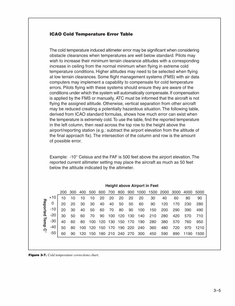
Figure 3-7. Cold temperature corrections chart.
ICAO Cold Temperature Error Table
The cold temperature induced altimeter error may be significant when consideringobstacle clearances when temperatures are well below standard. Pilots maywish to increase their minimum terrain clearance altitudes with a correspondingincrease in ceiling from the normal minimum when flying in extreme coldtemperature conditions. Higher altitudes may need to be selected when flyingat low terrain clearances. Some flight management systems (FMS) with air datacomputers may implement a capability to compensate for cold temperatureerrors. Pilots flying with these systems should ensure they are aware of theconditions under which the system will automatically compensate. If compensationis applied by the FMS or manually, ATC must be informed that the aircraft is notflying the assigned altitude. Otherwise, vertical separation from other aircraftmay be reduced creating a potentially hazardous situation. The following table,derived from ICAO standard formulas, shows how much error can exist whenthe temperature is extremely cold. To use the table, find the reported temperaturein the left column, then read across the top row to the height above theairport/reporting station (e.g.: subtract the airport elevation from the altitude ofthe final approach fix). The intersection of the column and row is the amountof possible error.
Example: -10° Celsius and the FAF is 500 feet above the airport elevation. Thereported current altimeter setting may place the aircraft as much as 50 feetbelow the altitude indicated by the altimeter.
Rep
orted
Temp
C°
Height above Airport in Feet
+10
0
-10
-20
-30
-40
-50
200
10
20
20
30
40
50
60
300
10
20
30
50
60
80
90
400
10
30
40
60
80
100
120
500
10
30
50
70
100
120
150
600
20
40
60
90
120
150
180
700
20
40
70
100
130
170
210
800
20
50
80
120
150
190
240
900
20
50
90
130
170
220
270
1000
20
60
100
140
190
240
300
1500
30
90
150
210
280
360
450
2000
40
120
200
280
380
480
590
3000
60
170
290
420
570
720
890
4000
80
230
390
570
760
970
1190
5000
90
280
490
710
950
1210
1500
3–6
Memory Aid:When flying from hot to cold, or from a high to a low, look out below!
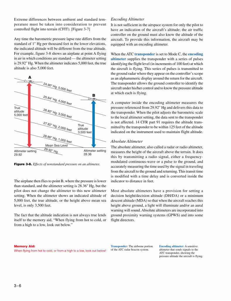
Figure 3-8. Effects of nonstandard pressure on an altimeter.
Transponder: The airborne portionof the ATC radar beacon system.
Encoding altimeter: A sensitivealtimeter that sends signals to theATC transponder, showing thepressure altitude the aircraft is flying.
Extreme differences between ambient and standard tem-perature must be taken into consideration to preventcontrolled flight into terrain (CFIT). [Figure 3-7]
Any time the barometric pressure lapse rate differs from thestandard of 1" Hg per thousand feet in the lower elevations,the indicated altitude will be different from the true altitude.For example, figure 3-8 shows an airplane at point A flyingin air in which conditions are standard — the altimeter settingis 29.92" Hg. When the altimeter indicates 5,000 feet, the truealtitude is also 5,000 feet.
Encoding AltimeterIt is not sufficient in the airspace system for only the pilot tohave an indication of the aircraft’s altitude; the air trafficcontroller on the ground must also know the altitude of theaircraft. To provide this information, the aircraft may beequipped with an encoding altimeter.
When the ATC transponder is set to Mode C, the encodingaltimeter supplies the transponder with a series of pulsesidentifying the flight level (in increments of 100 feet) at whichthe aircraft is flying. This series of pulses is transmitted tothe ground radar where they appear on the controller’s scopeas an alphanumeric display around the return for the aircraft.The transponder allows the ground controller to identify theaircraft under his/her control and to know the pressure altitudeat which each is flying.
A computer inside the encoding altimeter measures thepressure referenced from 29.92" Hg and delivers this data tothe transponder. When the pilot adjusts the barometric scaleto the local altimeter setting, the data sent to the transponderis not affected. 14 CFR part 91 requires the altitude trans-mitted by the transponder to be within 125 feet of the altitudeindicated on the instrument used to maintain flight altitude.
Absolute AltimeterThe absolute altimeter, also called a radar or radio altimeter,measures the height of the aircraft above the terrain. It doesthis by transmitting a radio signal, either a frequency-modulated continuous-wave or a pulse to the ground, andaccurately measuring the time used by the signal in travelingfrom the aircraft to the ground and returning. This transit timeis modified with a time delay and is converted inside theindicator to distance in feet.
Most absolute altimeters have a provision for setting adecision height/decision altitude (DH/DA) or a minimumdescent altitude (MDA) so that when the aircraft reaches thisheight above ground, a light will illuminate and/or an auralwarning will sound. Absolute altimeters are incorporated intoground proximity warning systems (GPWS) and into someflight directors.
The airplane then flies to point B, where the pressure is lowerthan standard, and the altimeter setting is 28.36" Hg, but thepilot does not change the altimeter to this new altimetersetting. When the altimeter shows an indicated altitude of5,000 feet, the true altitude, or the height above mean sealevel, is only 3,500 feet.
The fact that the altitude indication is not always true lendsitself to the memory aid, “When flying from hot to cold, orfrom a high to a low, look out below.”
3–7
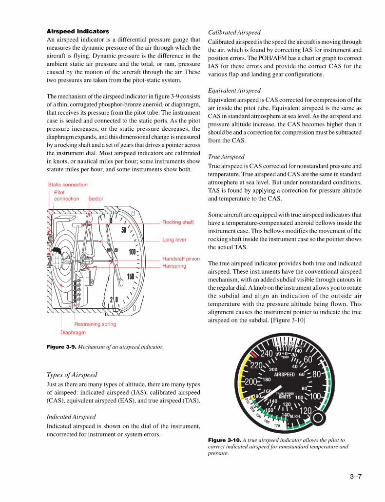
Figure 3-9. Mechanism of an airspeed indicator.
Airspeed IndicatorsAn airspeed indicator is a differential pressure gauge thatmeasures the dynamic pressure of the air through which theaircraft is flying. Dynamic pressure is the difference in theambient static air pressure and the total, or ram, pressurecaused by the motion of the aircraft through the air. Thesetwo pressures are taken from the pitot-static system.
The mechanism of the airspeed indicator in figure 3-9 consistsof a thin, corrugated phosphor-bronze aneroid, or diaphragm,that receives its pressure from the pitot tube. The instrumentcase is sealed and connected to the static ports. As the pitotpressure increases, or the static pressure decreases, thediaphragm expands, and this dimensional change is measuredby a rocking shaft and a set of gears that drives a pointer acrossthe instrument dial. Most airspeed indicators are calibratedin knots, or nautical miles per hour; some instruments showstatute miles per hour, and some instruments show both.
Calibrated Airspeed
Calibrated airspeed is the speed the aircraft is moving throughthe air, which is found by correcting IAS for instrument andposition errors. The POH/AFM has a chart or graph to correctIAS for these errors and provide the correct CAS for thevarious flap and landing gear configurations.
Equivalent Airspeed
Equivalent airspeed is CAS corrected for compression of theair inside the pitot tube. Equivalent airspeed is the same asCAS in standard atmosphere at sea level. As the airspeed andpressure altitude increase, the CAS becomes higher than itshould be and a correction for compression must be subtractedfrom the CAS.
True Airspeed
True airspeed is CAS corrected for nonstandard pressure andtemperature. True airspeed and CAS are the same in standardatmosphere at sea level. But under nonstandard conditions,TAS is found by applying a correction for pressure altitudeand temperature to the CAS.
Some aircraft are equipped with true airspeed indicators thathave a temperature-compensated aneroid bellows inside theinstrument case. This bellows modifies the movement of therocking shaft inside the instrument case so the pointer showsthe actual TAS.
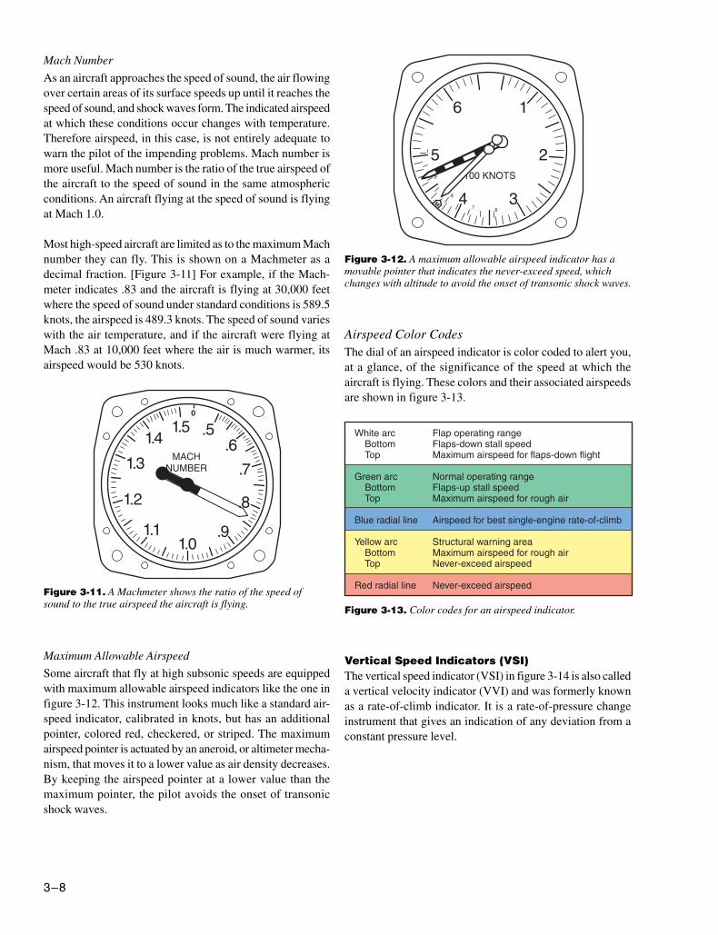
The true airspeed indicator provides both true and indicatedairspeed. These instruments have the conventional airspeedmechanism, with an added subdial visible through cutouts inthe regular dial. A knob on the instrument allows you to rotatethe subdial and align an indication of the outside airtemperature with the pressure altitude being flown. Thisalignment causes the instrument pointer to indicate the trueairspeed on the subdial. [Figure 3-10]
0 40
Figure 3-10. A true airspeed indicator allows the pilot tocorrect indicated airspeed for nonstandard temperature andpressure.
Types of AirspeedJust as there are many types of altitude, there are many typesof airspeed: indicated airspeed (IAS), calibrated airspeed(CAS), equivalent airspeed (EAS), and true airspeed (TAS).
Indicated Airspeed
Indicated airspeed is shown on the dial of the instrument,uncorrected for instrument or system errors.
3–8
Figure 3-11. A Machmeter shows the ratio of the speed ofsound to the true airspeed the aircraft is flying.
Mach Number
As an aircraft approaches the speed of sound, the air flowingover certain areas of its surface speeds up until it reaches thespeed of sound, and shock waves form. The indicated airspeedat which these conditions occur changes with temperature.Therefore airspeed, in this case, is not entirely adequate towarn the pilot of the impending problems. Mach number ismore useful. Mach number is the ratio of the true airspeed ofthe aircraft to the speed of sound in the same atmosphericconditions. An aircraft flying at the speed of sound is flyingat Mach 1.0.
Most high-speed aircraft are limited as to the maximum Machnumber they can fly. This is shown on a Machmeter as adecimal fraction. [Figure 3-11] For example, if the Mach-meter indicates .83 and the aircraft is flying at 30,000 feetwhere the speed of sound under standard conditions is 589.5knots, the airspeed is 489.3 knots. The speed of sound varieswith the air temperature, and if the aircraft were flying atMach .83 at 10,000 feet where the air is much warmer, itsairspeed would be 530 knots.
Airspeed Color CodesThe dial of an airspeed indicator is color coded to alert you,at a glance, of the significance of the speed at which theaircraft is flying. These colors and their associated airspeedsare shown in figure 3-13.
Figure 3-12. A maximum allowable airspeed indicator has amovable pointer that indicates the never-exceed speed, whichchanges with altitude to avoid the onset of transonic shock waves.
Figure 3-13. Color codes for an airspeed indicator.
Maximum Allowable Airspeed
Some aircraft that fly at high subsonic speeds are equippedwith maximum allowable airspeed indicators like the one infigure 3-12. This instrument looks much like a standard air-speed indicator, calibrated in knots, but has an additionalpointer, colored red, checkered, or striped. The maximumairspeed pointer is actuated by an aneroid, or altimeter mecha-nism, that moves it to a lower value as air density decreases.By keeping the airspeed pointer at a lower value than themaximum pointer, the pilot avoids the onset of transonicshock waves.
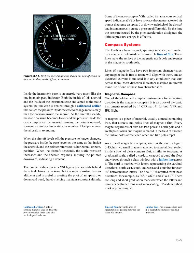
Vertical Speed Indicators (VSI)The vertical speed indicator (VSI) in figure 3-14 is also calleda vertical velocity indicator (VVI) and was formerly knownas a rate-of-climb indicator. It is a rate-of-pressure changeinstrument that gives an indication of any deviation from aconstant pressure level.
3–9
Calibrated orifice: A hole ofspecific diameter used to delay thepressure change in the case of avertical speed indicator.
Lines of flux: Invisible lines ofmagnetic force passing between thepoles of a magnet.
Inside the instrument case is an aneroid very much like theone in an airspeed indicator. Both the inside of this aneroidand the inside of the instrument case are vented to the staticsystem, but the case is vented through a calibrated orificethat causes the pressure inside the case to change more slowlythan the pressure inside the aneroid. As the aircraft ascends,the static pressure becomes lower and the pressure inside thecase compresses the aneroid, moving the pointer upward,showing a climb and indicating the number of feet per minutethe aircraft is ascending.
When the aircraft levels off, the pressure no longer changes,the pressure inside the case becomes the same as that insidethe aneroid, and the pointer returns to its horizontal, or zero,position. When the aircraft descends, the static pressureincreases and the aneroid expands, moving the pointerdownward, indicating a descent.
The pointer indication in a VSI lags a few seconds behindthe actual change in pressure, but it is more sensitive than analtimeter and is useful in alerting the pilot of an upward ordownward trend, thereby helping maintain a constant altitude.
Some of the more complex VSIs, called instantaneous verticalspeed indicators (IVSI), have two accelerometer-actuated airpumps that sense an upward or downward pitch of the aircraftand instantaneously create a pressure differential. By the timethe pressure caused by the pitch acceleration dissipates, thealtitude pressure change is effective.
Compass SystemsThe Earth is a huge magnet, spinning in space, surroundedby a magnetic field made up of invisible lines of flux. Theselines leave the surface at the magnetic north pole and reenterat the magnetic south pole.
Lines of magnetic flux have two important characteristics:any magnet that is free to rotate will align with them, and anelectrical current is induced into any conductor that cutsacross them. Most direction indicators installed in aircraftmake use of one of these two characteristics.
Magnetic CompassOne of the oldest and simplest instruments for indicatingdirection is the magnetic compass. It is also one of the basicinstruments required by 14 CFR part 91 for both VFR andIFR flight.
A magnet is a piece of material, usually a metal containingiron, that attracts and holds lines of magnetic flux. Everymagnet regardless of size has two poles: a north pole and asouth pole. When one magnet is placed in the field of another,the unlike poles attract each other and like poles repel.
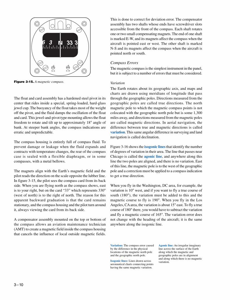
An aircraft magnetic compass, such as the one in figure3-15, has two small magnets attached to a metal float sealedinside a bowl of clear compass fluid similar to kerosene. Agraduated scale, called a card, is wrapped around the floatand viewed through a glass window with a lubber line acrossit. The card is marked with letters representing the cardinaldirections, north, east, south, and west, and a number for each30° between these letters. The final “0” is omitted from thesedirections; for example, 3 = 30°, 6 = 60°, and 33 = 330°. Thereare long and short graduation marks between the letters andnumbers, with each long mark representing 10° and each shortmark representing 5°.
Figure 3-14. Vertical speed indicator shows the rate of climb ordescent in thousands of feet per minute.
Lubber line: The reference line usedin a magnetic compass or headingindicator.
3–10
E–WN–S
Figure 3-15. A magnetic compass.
Variation: The compass error causedby the difference in the physicallocations of the magnetic north poleand the geographic north pole.
Isogonic lines: Lines drawn acrossaeronautical charts connecting pointshaving the same magnetic variation.
Agonic line: An irregular imaginaryline across the surface of the Earthalong which the magnetic andgeographic poles are in alignmentand along which there is no magneticvariation.
This is done to correct for deviation error. The compensatorassembly has two shafts whose ends have screwdriver slotsaccessible from the front of the compass. Each shaft rotatesone or two small compensating magnets. The end of one shaftis marked E-W, and its magnets affect the compass when theaircraft is pointed east or west. The other shaft is markedN-S and its magnets affect the compass when the aircraft ispointed north or south.
Compass ErrorsThe magnetic compass is the simplest instrument in the panel,but it is subject to a number of errors that must be considered.
Variation
The Earth rotates about its geographic axis, and maps andcharts are drawn using meridians of longitude that passthrough the geographic poles. Directions measured from thegeographic poles are called true directions. The northmagnetic pole to which the magnetic compass points is notcolocated with the geographic north pole but is some 1,300miles away, and directions measured from the magnetic polesare called magnetic directions. In aerial navigation, thedifference between true and magnetic directions is calledvariation. This same angular difference in surveying and landnavigation is called declination.
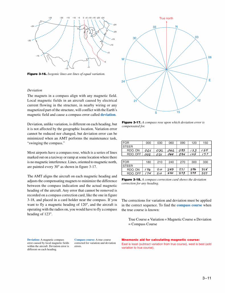
Figure 3-16 shows the isogonic lines that identify the numberof degrees of variation in their area. The line that passes nearChicago is called the agonic line, and anywhere along thisline the two poles are aligned, and there is no variation. Eastof this line, the magnetic pole is to the west of the geographicpole and a correction must be applied to a compass indicationto get a true direction.
When you fly in the Washington, DC area, for example, thevariation is 10° west, and if you want to fly a true course ofsouth (180°), the variation must be added to this and themagnetic course to fly is 190°. When you fly in the LosAngeles, CA area, the variation is about 15° east. To fly a truecourse of 180° there, you would have to subtract the variationand fly a magnetic course of 165°. The variation error doesnot change with the heading of the aircraft; it is the sameanywhere along the isogonic line.
The float and card assembly has a hardened steel pivot in itscenter that rides inside a special, spring-loaded, hard-glassjewel cup. The buoyancy of the float takes most of the weightoff the pivot, and the fluid damps the oscillation of the floatand card. This jewel-and-pivot type mounting allows the floatfreedom to rotate and tilt up to approximately 18° angle ofbank. At steeper bank angles, the compass indications areerratic and unpredictable.
The compass housing is entirely full of compass fluid. Toprevent damage or leakage when the fluid expands andcontracts with temperature changes, the rear of the compasscase is sealed with a flexible diaphragm, or in somecompasses, with a metal bellows.
The magnets align with the Earth’s magnetic field and thepilot reads the direction on the scale opposite the lubber line.In figure 3-15, the pilot sees the compass card from its backside. When you are flying north as the compass shows, eastis to your right, but on the card “33” which represents 330°(west of north) is to the right of north. The reason for thisapparent backward graduation is that the card remainsstationary, and the compass housing and the pilot turn aroundit, always viewing the card from its back side.
A compensator assembly mounted on the top or bottom ofthe compass allows an aviation maintenance technician(AMT) to create a magnetic field inside the compass housingthat cancels the influence of local outside magnetic fields.
3–11
Mnemonic aid for calculating magnetic course:East is least (subtract variation from true course), west is best (addvariation to true course).
Figure 3-16. Isogonic lines are lines of equal variation.
Deviation: A magnetic compasserror caused by local magnetic fieldswithin the aircraft. Deviation error isdifferent on each heading.
Figure 3-17. A compass rose upon which deviation error iscompensated for.
Deviation
The magnets in a compass align with any magnetic field.Local magnetic fields in an aircraft caused by electricalcurrent flowing in the structure, in nearby wiring or anymagnetized part of the structure, will conflict with the Earth’smagnetic field and cause a compass error called deviation.
Deviation, unlike variation, is different on each heading, butit is not affected by the geographic location. Variation errorcannot be reduced nor changed, but deviation error can beminimized when an AMT performs the maintenance task,“swinging the compass.”
Most airports have a compass rose, which is a series of linesmarked out on a taxiway or ramp at some location where thereis no magnetic interference. Lines, oriented to magnetic north,are painted every 30° as shown in figure 3-17.
The AMT aligns the aircraft on each magnetic heading andadjusts the compensating magnets to minimize the differencebetween the compass indication and the actual magneticheading of the aircraft. Any error that cannot be removed isrecorded on a compass correction card, like the one in figure3-18, and placed in a card holder near the compass. If youwant to fly a magnetic heading of 120°, and the aircraft isoperating with the radios on, you would have to fly a compassheading of 123°.
Compass course: A true coursecorrected for variation and deviationerrors.
Figure 3-18. A compass correction card shows the deviationcorrection for any heading.
The corrections for variation and deviation must be appliedin the correct sequence. To find the compass course whenthe true course is known:
True Course ± Variation = Magnetic Course ± Deviation= Compass Course
3–12
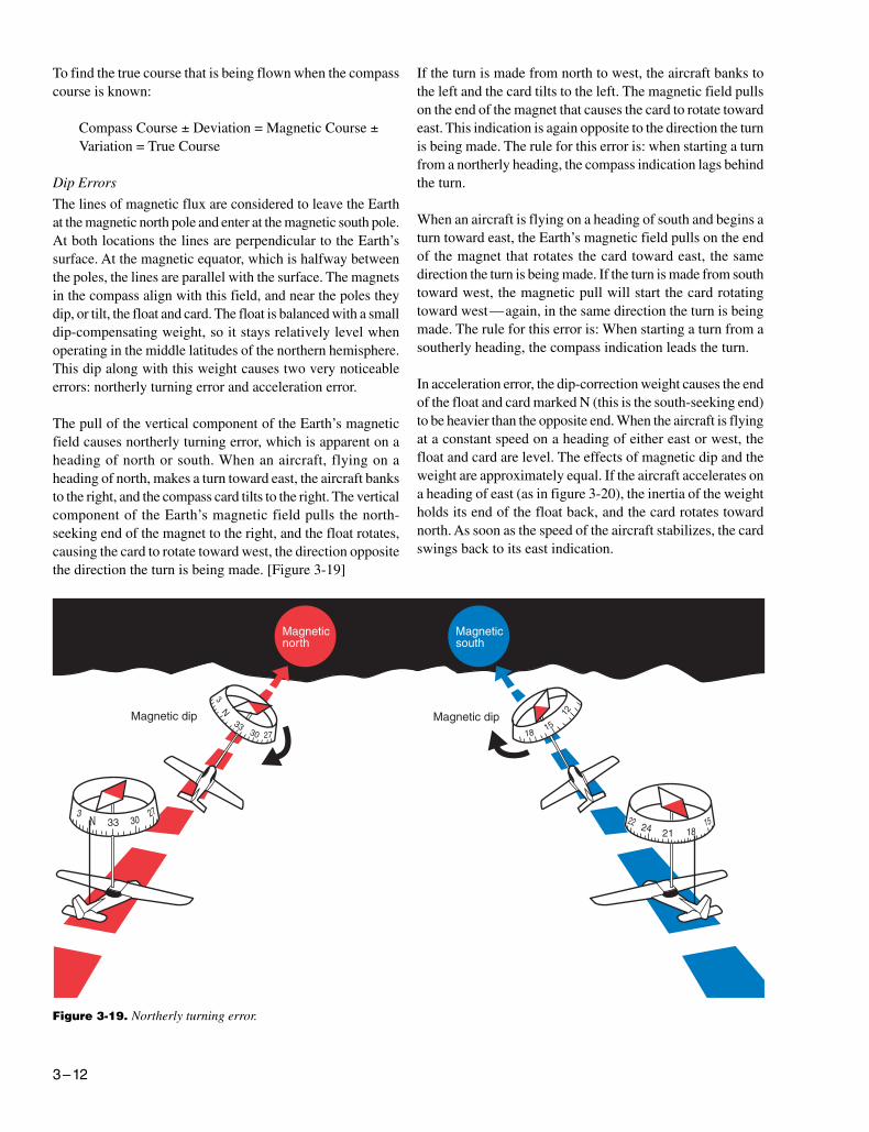
Figure 3-19. Northerly turning error.
To find the true course that is being flown when the compasscourse is known:
Compass Course ± Deviation = Magnetic Course ±Variation = True Course
Dip Errors
The lines of magnetic flux are considered to leave the Earthat the magnetic north pole and enter at the magnetic south pole.At both locations the lines are perpendicular to the Earth’ssurface. At the magnetic equator, which is halfway betweenthe poles, the lines are parallel with the surface. The magnetsin the compass align with this field, and near the poles theydip, or tilt, the float and card. The float is balanced with a smalldip-compensating weight, so it stays relatively level whenoperating in the middle latitudes of the northern hemisphere.This dip along with this weight causes two very noticeableerrors: northerly turning error and acceleration error.
The pull of the vertical component of the Earth’s magneticfield causes northerly turning error, which is apparent on aheading of north or south. When an aircraft, flying on aheading of north, makes a turn toward east, the aircraft banksto the right, and the compass card tilts to the right. The verticalcomponent of the Earth’s magnetic field pulls the north-seeking end of the magnet to the right, and the float rotates,causing the card to rotate toward west, the direction oppositethe direction the turn is being made. [Figure 3-19]
If the turn is made from north to west, the aircraft banks tothe left and the card tilts to the left. The magnetic field pullson the end of the magnet that causes the card to rotate towardeast. This indication is again opposite to the direction the turnis being made. The rule for this error is: when starting a turnfrom a northerly heading, the compass indication lags behindthe turn.
When an aircraft is flying on a heading of south and begins aturn toward east, the Earth’s magnetic field pulls on the endof the magnet that rotates the card toward east, the samedirection the turn is being made. If the turn is made from southtoward west, the magnetic pull will start the card rotatingtoward west—again, in the same direction the turn is beingmade. The rule for this error is: When starting a turn from asoutherly heading, the compass indication leads the turn.
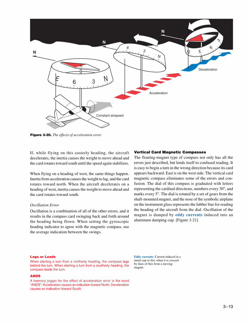
In acceleration error, the dip-correction weight causes the endof the float and card marked N (this is the south-seeking end)to be heavier than the opposite end. When the aircraft is flyingat a constant speed on a heading of either east or west, thefloat and card are level. The effects of magnetic dip and theweight are approximately equal. If the aircraft accelerates ona heading of east (as in figure 3-20), the inertia of the weightholds its end of the float back, and the card rotates towardnorth. As soon as the speed of the aircraft stabilizes, the cardswings back to its east indication.
3–13
Figure 3-20. The effects of acceleration error.
Lags or LeadsWhen starting a turn from a northerly heading, the compass lagsbehind the turn. When starting a turn from a southerly heading, thecompass leads the turn.
ANDSA memory jogger for the effect of acceleration error is the word“ANDS”: Acceleration causes an indication toward North, Decelerationcauses an indication toward South.
Eddy currents: Current induced in ametal cup or disc when it is crossedby lines of flux from a movingmagnet.
If, while flying on this easterly heading, the aircraftdecelerates, the inertia causes the weight to move ahead andthe card rotates toward south until the speed again stabilizes.
When flying on a heading of west, the same things happen.Inertia from acceleration causes the weight to lag, and the cardrotates toward north. When the aircraft decelerates on aheading of west, inertia causes the weight to move ahead andthe card rotates toward south.
Oscillation Error
Oscillation is a combination of all of the other errors, and itresults in the compass card swinging back and forth aroundthe heading being flown. When setting the gyroscopicheading indicator to agree with the magnetic compass, usethe average indication between the swings.
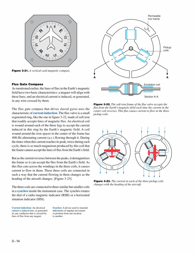
Vertical Card Magnetic CompassesThe floating-magnet type of compass not only has all theerrors just described, but lends itself to confused reading. Itis easy to begin a turn in the wrong direction because its cardappears backward. East is on the west side. The vertical cardmagnetic compass eliminates some of the errors and con-fusion. The dial of this compass is graduated with lettersrepresenting the cardinal directions, numbers every 30°, andmarks every 5°. The dial is rotated by a set of gears from theshaft-mounted magnet, and the nose of the symbolic airplaneon the instrument glass represents the lubber line for readingthe heading of the aircraft from the dial. Oscillation of themagnet is damped by eddy currents induced into analuminum damping cup. [Figure 3-21]
3–14
Current induction: An electricalcurrent is induced into, or generatedin, any conductor that is crossed bylines of flux from any magnet.
Figure 3-23. The current in each of the three pickup coilschanges with the heading of the aircraft.
Synchro: A device used to transmitindications of angular movementor position from one locationto another.
Figure 3-21. A vertical card magnetic compass.
Figure 3-22. The soft iron frame of the flux valve accepts theflux from the Earth’s magnetic field each time the current in thecenter coil reverses. This flux causes current to flow in the threepickup coils.
Flux Gate CompassAs mentioned earlier, the lines of flux in the Earth’s magneticfield have two basic characteristics: a magnet will align withthese lines, and an electrical current is induced, or generated,in any wire crossed by them.
The flux gate compass that drives slaved gyros uses thecharacteristic of current induction. The flux valve is a smallsegmented ring, like the one in figure 3-22, made of soft ironthat readily accepts lines of magnetic flux. An electrical coilis wound around each of the three legs to accept the currentinduced in this ring by the Earth’s magnetic field. A coilwound around the iron spacer in the center of the frame has400-Hz alternating current (a.c.) flowing through it. Duringthe times when this current reaches its peak, twice during eachcycle, there is so much magnetism produced by this coil thatthe frame cannot accept the lines of flux from the Earth’s field.
But as the current reverses between the peaks, it demagnetizesthe frame so it can accept the flux from the Earth’s field. Asthis flux cuts across the windings in the three coils, it causescurrent to flow in them. These three coils are connected insuch a way that the current flowing in them changes as theheading of the aircraft changes. [Figure 3-23]
The three coils are connected to three similar but smaller coilsin a synchro inside the instrument case. The synchro rotatesthe dial of a radio magnetic indicator (RMI) or a horizontalsituation indicator (HSI).
3–15
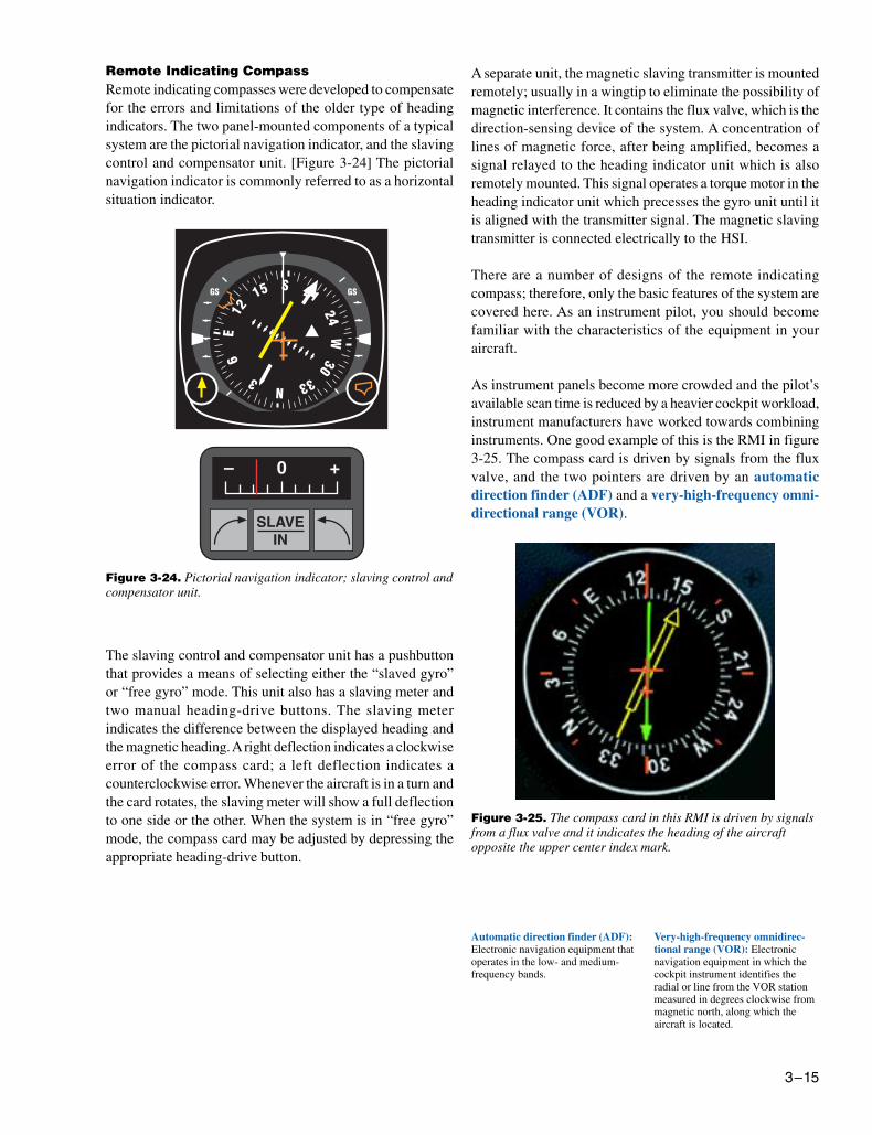
Figure 3-24. Pictorial navigation indicator; slaving control andcompensator unit.
Remote Indicating CompassRemote indicating compasses were developed to compensatefor the errors and limitations of the older type of headingindicators. The two panel-mounted components of a typicalsystem are the pictorial navigation indicator, and the slavingcontrol and compensator unit. [Figure 3-24] The pictorialnavigation indicator is commonly referred to as a horizontalsituation indicator.
The slaving control and compensator unit has a pushbuttonthat provides a means of selecting either the “slaved gyro”or “free gyro” mode. This unit also has a slaving meter andtwo manual heading-drive buttons. The slaving meterindicates the difference between the displayed heading andthe magnetic heading. A right deflection indicates a clockwiseerror of the compass card; a left deflection indicates acounterclockwise error. Whenever the aircraft is in a turn andthe card rotates, the slaving meter will show a full deflectionto one side or the other. When the system is in “free gyro”mode, the compass card may be adjusted by depressing theappropriate heading-drive button.
A separate unit, the magnetic slaving transmitter is mountedremotely; usually in a wingtip to eliminate the possibility ofmagnetic interference. It contains the flux valve, which is thedirection-sensing device of the system. A concentration oflines of magnetic force, after being amplified, becomes asignal relayed to the heading indicator unit which is alsoremotely mounted. This signal operates a torque motor in theheading indicator unit which precesses the gyro unit until itis aligned with the transmitter signal. The magnetic slavingtransmitter is connected electrically to the HSI.
There are a number of designs of the remote indicatingcompass; therefore, only the basic features of the system arecovered here. As an instrument pilot, you should becomefamiliar with the characteristics of the equipment in youraircraft.
As instrument panels become more crowded and the pilot’savailable scan time is reduced by a heavier cockpit workload,instrument manufacturers have worked towards combininginstruments. One good example of this is the RMI in figure3-25. The compass card is driven by signals from the fluxvalve, and the two pointers are driven by an automaticdirection finder (ADF) and a very-high-frequency omni-directional range (VOR).
Automatic direction finder (ADF):Electronic navigation equipment thatoperates in the low- and medium-frequency bands.
Very-high-frequency omnidirec-tional range (VOR): Electronicnavigation equipment in which thecockpit instrument identifies theradial or line from the VOR stationmeasured in degrees clockwise frommagnetic north, along which theaircraft is located.
Figure 3-25. The compass card in this RMI is driven by signalsfrom a flux valve and it indicates the heading of the aircraftopposite the upper center index mark.
3–16
Gyroscopic SystemsFlight without reference to a visible horizon can be safelyaccomplished by the use of gyroscopic instrument systemsand the two characteristics of gyroscopes which are: rigidityand precession. These systems include: attitude, heading, andrate instruments, along with their power sources. Theseinstruments include a gyroscope (or gyro) which is a smallwheel with its weight concentrated around its periphery.When this wheel is spun at high speed, it becomes rigid andresists any attempt to tilt it or turn it in any direction otherthan around its spin axis.
Attitude and heading instruments operate on the principal ofrigidity. For these instruments the gyro remains rigid in itscase and the aircraft rotates about it.
Rate indicators, such as turn indicators and turn coordinators,operate on the principal of precession. In this case the gyroprecesses (or rolls over) proportionate to the rate the aircraftrotates about one or more of its axes.
Power SourcesAircraft and instrument manufacturers have designed re-dundancy into the flight instruments so that any single failurewill not deprive the pilot of his/her ability to safely concludethe flight.
Gyroscopic instruments are crucial for instrument flight;therefore, they are powered by separate electrical orpneumatic sources.
Electrical SystemsMany general aviation aircraft that use pneumatic attitudeindicators use electric rate indicators and vice versa. Someinstruments identify their power source on their dial, but it isextremely important that pilots consult the POH/AFM todetermine the power source of all instruments to know whataction to take in the event of an instrument failure.
Direct current (d.c.) electrical instruments are available in14- or 28-volt models, depending upon the electrical systemin the aircraft. Alternating current (a.c.) is used to operatesome attitude gyros and autopilots. Aircraft that have onlyd.c. electrical systems can use a.c. instruments by installinga solid-state d.c. to a.c. inverter, which changes 14 or 28 voltsd.c. into three-phase 115-volt, 400-Hz a.c.
Pneumatic SystemsPneumatic gyros are driven by a jet of air impinging onbuckets cut into the periphery of the wheel. This stream ofair is obtained on many aircraft by evacuating the instrumentcase and allowing filtered air to flow into the case through anozzle to spin the wheel.
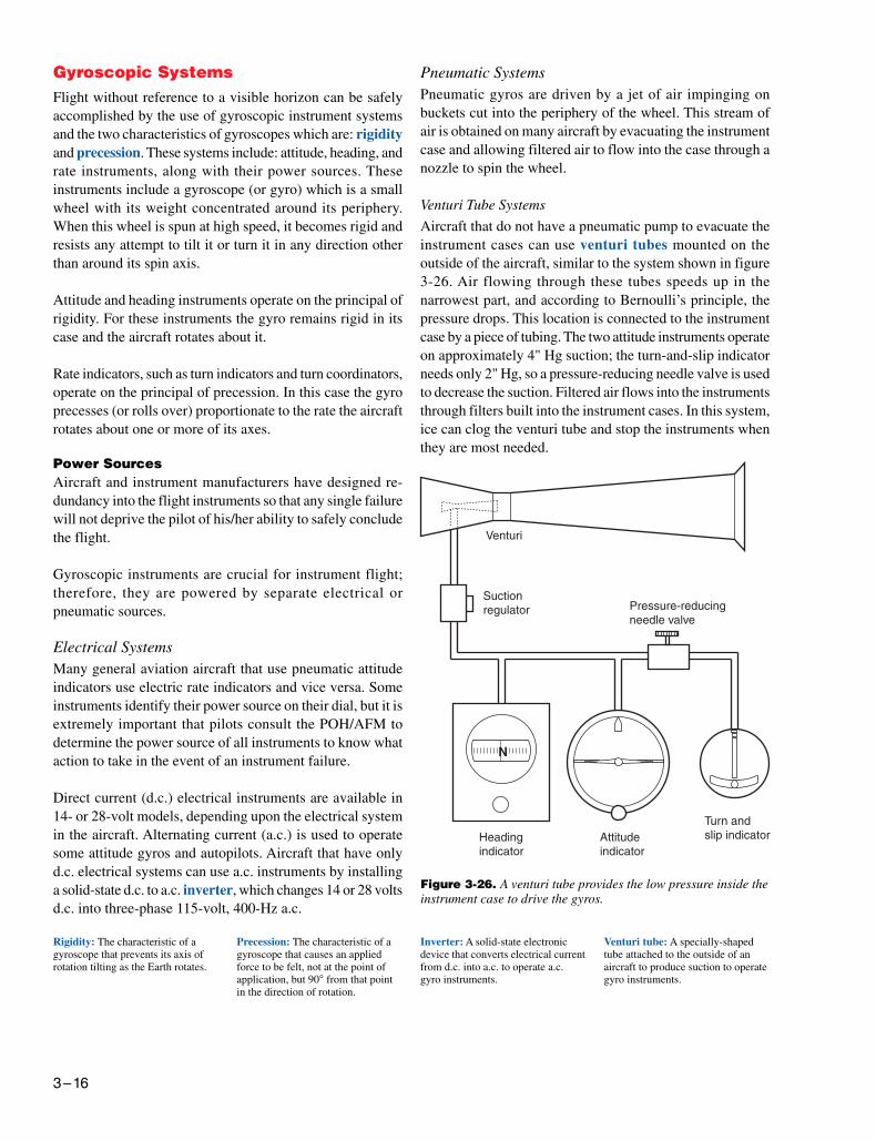
Venturi Tube Systems
Aircraft that do not have a pneumatic pump to evacuate theinstrument cases can use venturi tubes mounted on theoutside of the aircraft, similar to the system shown in figure3-26. Air flowing through these tubes speeds up in thenarrowest part, and according to Bernoulli’s principle, thepressure drops. This location is connected to the instrumentcase by a piece of tubing. The two attitude instruments operateon approximately 4" Hg suction; the turn-and-slip indicatorneeds only 2" Hg, so a pressure-reducing needle valve is usedto decrease the suction. Filtered air flows into the instrumentsthrough filters built into the instrument cases. In this system,ice can clog the venturi tube and stop the instruments whenthey are most needed.
Figure 3-26. A venturi tube provides the low pressure inside theinstrument case to drive the gyros.
Venturi tube: A specially-shapedtube attached to the outside of anaircraft to produce suction to operategyro instruments.
Rigidity: The characteristic of agyroscope that prevents its axis ofrotation tilting as the Earth rotates.
Precession: The characteristic of agyroscope that causes an appliedforce to be felt, not at the point ofapplication, but 90° from that pointin the direction of rotation.
Inverter: A solid-state electronicdevice that converts electrical currentfrom d.c. into a.c. to operate a.c.gyro instruments.
3–17
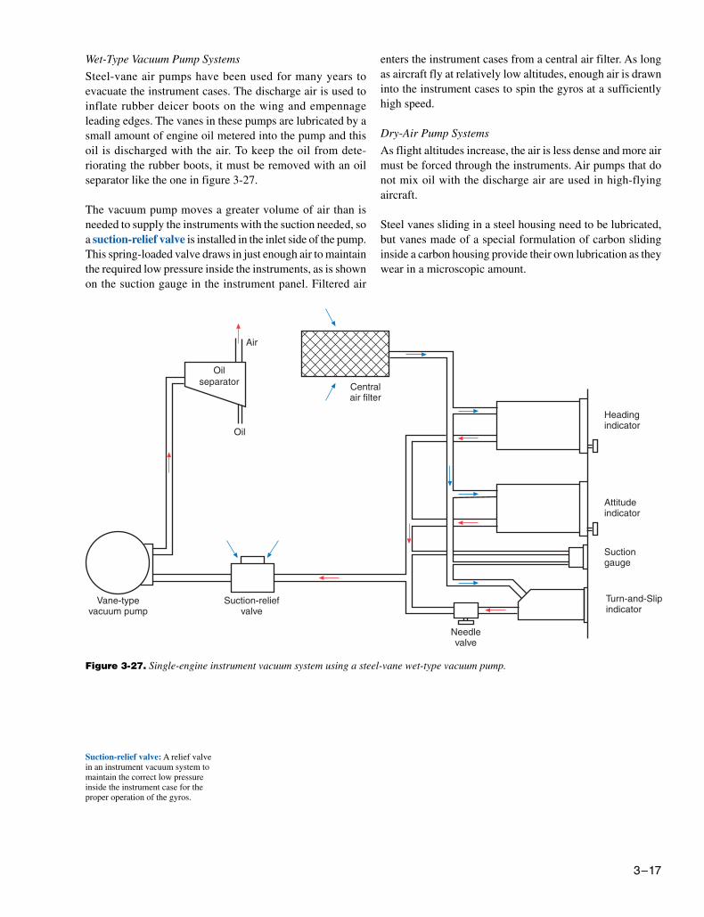
Wet-Type Vacuum Pump Systems
Steel-vane air pumps have been used for many years toevacuate the instrument cases. The discharge air is used toinflate rubber deicer boots on the wing and empennageleading edges. The vanes in these pumps are lubricated by asmall amount of engine oil metered into the pump and thisoil is discharged with the air. To keep the oil from dete-riorating the rubber boots, it must be removed with an oilseparator like the one in figure 3-27.
The vacuum pump moves a greater volume of air than isneeded to supply the instruments with the suction needed, soa suction-relief valve is installed in the inlet side of the pump.This spring-loaded valve draws in just enough air to maintainthe required low pressure inside the instruments, as is shownon the suction gauge in the instrument panel. Filtered air
enters the instrument cases from a central air filter. As longas aircraft fly at relatively low altitudes, enough air is drawninto the instrument cases to spin the gyros at a sufficientlyhigh speed.
Dry-Air Pump Systems
As flight altitudes increase, the air is less dense and more airmust be forced through the instruments. Air pumps that donot mix oil with the discharge air are used in high-flyingaircraft.
Steel vanes sliding in a steel housing need to be lubricated,but vanes made of a special formulation of carbon slidinginside a carbon housing provide their own lubrication as theywear in a microscopic amount.
Figure 3-27. Single-engine instrument vacuum system using a steel-vane wet-type vacuum pump.
Suction-relief valve: A relief valvein an instrument vacuum system tomaintain the correct low pressureinside the instrument case for theproper operation of the gyros.
3–18
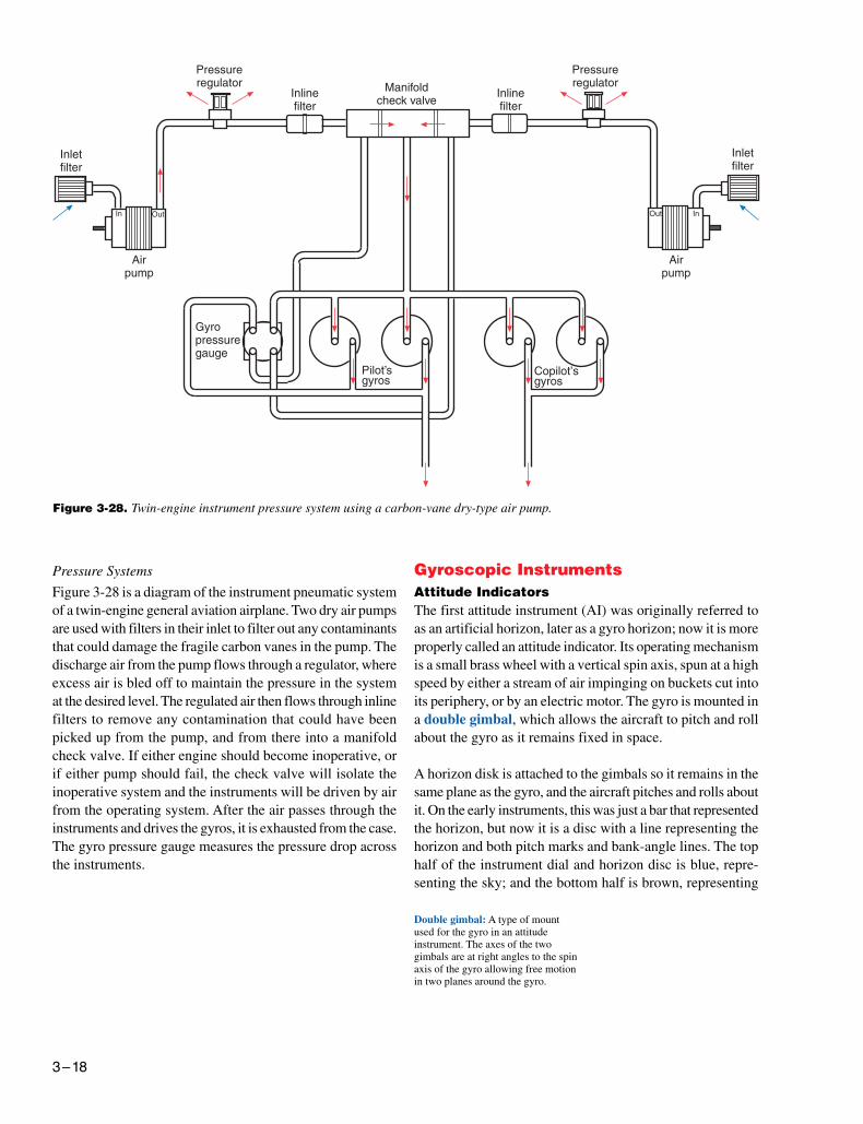
Figure 3-28. Twin-engine instrument pressure system using a carbon-vane dry-type air pump.
Double gimbal: A type of mountused for the gyro in an attitudeinstrument. The axes of the twogimbals are at right angles to the spinaxis of the gyro allowing free motionin two planes around the gyro.
Pressure Systems
Figure 3-28 is a diagram of the instrument pneumatic systemof a twin-engine general aviation airplane. Two dry air pumpsare used with filters in their inlet to filter out any contaminantsthat could damage the fragile carbon vanes in the pump. Thedischarge air from the pump flows through a regulator, whereexcess air is bled off to maintain the pressure in the systemat the desired level. The regulated air then flows through inlinefilters to remove any contamination that could have beenpicked up from the pump, and from there into a manifoldcheck valve. If either engine should become inoperative, orif either pump should fail, the check valve will isolate theinoperative system and the instruments will be driven by airfrom the operating system. After the air passes through theinstruments and drives the gyros, it is exhausted from the case.The gyro pressure gauge measures the pressure drop acrossthe instruments.
Gyroscopic InstrumentsAttitude IndicatorsThe first attitude instrument (AI) was originally referred toas an artificial horizon, later as a gyro horizon; now it is moreproperly called an attitude indicator. Its operating mechanismis a small brass wheel with a vertical spin axis, spun at a highspeed by either a stream of air impinging on buckets cut intoits periphery, or by an electric motor. The gyro is mounted ina double gimbal, which allows the aircraft to pitch and rollabout the gyro as it remains fixed in space.
A horizon disk is attached to the gimbals so it remains in thesame plane as the gyro, and the aircraft pitches and rolls aboutit. On the early instruments, this was just a bar that representedthe horizon, but now it is a disc with a line representing thehorizon and both pitch marks and bank-angle lines. The tophalf of the instrument dial and horizon disc is blue, repre-senting the sky; and the bottom half is brown, representing
3–19
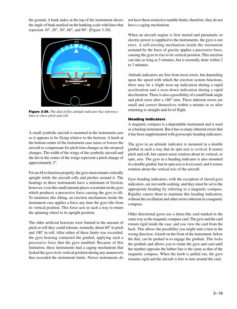
the ground. A bank index at the top of the instrument showsthe angle of bank marked on the banking scale with lines thatrepresent 10°, 20°, 30°, 60°, and 90°. [Figure 3-29]
not have these restrictive tumble limits; therefore, they do nothave a caging mechanism.
When an aircraft engine is first started and pneumatic orelectric power is supplied to the instruments, the gyro is noterect. A self-erecting mechanism inside the instrumentactuated by the force of gravity applies a precessive force,causing the gyro to rise to its vertical position. This erectioncan take as long as 5 minutes, but is normally done within 2to 3 minutes.
Attitude indicators are free from most errors, but dependingupon the speed with which the erection system functions,there may be a slight nose-up indication during a rapidacceleration and a nose-down indication during a rapiddeceleration. There is also a possibility of a small bank angleand pitch error after a 180° turn. These inherent errors aresmall and correct themselves within a minute or so afterreturning to straight-and-level flight.
Heading IndicatorsA magnetic compass is a dependable instrument and is usedas a backup instrument. But it has so many inherent errors thatit has been supplemented with gyroscopic heading indicators.
The gyro in an attitude indicator is mounted in a doublegimbal in such a way that its spin axis is vertical. It sensespitch and roll, but cannot sense rotation about its vertical, orspin, axis. The gyro in a heading indicator is also mountedin a double gimbal, but its spin axis is horizontal, and it sensesrotation about the vertical axis of the aircraft.
Gyro heading indicators, with the exception of slaved gyroindicators, are not north-seeking, and they must be set to theappropriate heading by referring to a magnetic compass.Rigidity causes them to maintain this heading indication,without the oscillation and other errors inherent in a magneticcompass.
Older directional gyros use a drum-like card marked in thesame way as the magnetic compass card. The gyro and the cardremain rigid inside the case, and you view the card from theback. This allows the possibility you might start a turn in thewrong direction. A knob on the front of the instrument, belowthe dial, can be pushed in to engage the gimbals. This locksthe gimbals and allows you to rotate the gyro and card untilthe number opposite the lubber line is the same as that of themagnetic compass. When the knob is pulled out, the gyroremains rigid and the aircraft is free to turn around the card.
Figure 3-29. The dial of this attitude indicator has referencelines to show pitch and roll.
A small symbolic aircraft is mounted in the instrument caseso it appears to be flying relative to the horizon. A knob atthe bottom center of the instrument case raises or lowers theaircraft to compensate for pitch trim changes as the airspeedchanges. The width of the wings of the symbolic aircraft andthe dot in the center of the wings represent a pitch change ofapproximately 2°.
For an AI to function properly, the gyro must remain verticallyupright while the aircraft rolls and pitches around it. Thebearings in these instruments have a minimum of friction;however, even this small amount places a restraint on the gyrowhich produces a precessive force causing the gyro to tilt.To minimize this tilting, an erection mechanism inside theinstrument case applies a force any time the gyro tilts fromits vertical position. This force acts in such a way to returnthe spinning wheel to its upright position.
The older artificial horizons were limited in the amount ofpitch or roll they could tolerate, normally about 60° in pitchand 100° in roll. After either of these limits was exceeded,the gyro housing contacted the gimbal, applying such aprecessive force that the gyro tumbled. Because of thislimitation, these instruments had a caging mechanism thatlocked the gyro in its vertical position during any maneuversthat exceeded the instrument limits. Newer instruments do
3–20
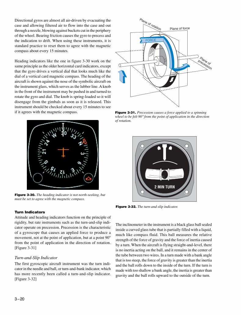
Directional gyros are almost all air-driven by evacuating thecase and allowing filtered air to flow into the case and outthrough a nozzle, blowing against buckets cut in the peripheryof the wheel. Bearing friction causes the gyro to precess andthe indication to drift. When using these instruments, it isstandard practice to reset them to agree with the magneticcompass about every 15 minutes.
Heading indicators like the one in figure 3-30 work on thesame principle as the older horizontal card indicators, exceptthat the gyro drives a vertical dial that looks much like thedial of a vertical card magnetic compass. The heading of theaircraft is shown against the nose of the symbolic aircraft onthe instrument glass, which serves as the lubber line. A knobin the front of the instrument may be pushed in and turned torotate the gyro and dial. The knob is spring-loaded so it willdisengage from the gimbals as soon as it is released. Thisinstrument should be checked about every 15 minutes to seeif it agrees with the magnetic compass.
Figure 3-30. The heading indicator is not north-seeking, butmust be set to agree with the magnetic compass.
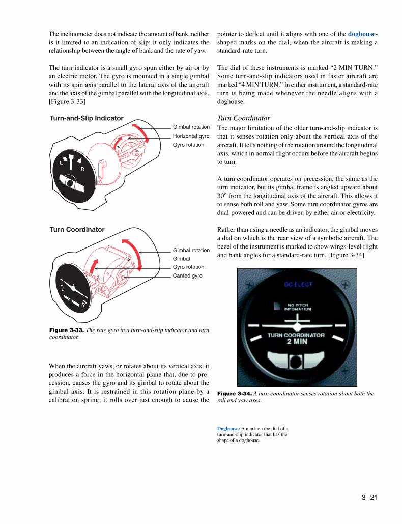
Figure 3-32. The turn-and-slip indicator.
Figure 3-31. Precession causes a force applied to a spinningwheel to be felt 90° from the point of application in the directionof rotation.
Turn IndicatorsAttitude and heading indicators function on the principle ofrigidity, but rate instruments such as the turn-and-slip indi-cator operate on precession. Precession is the characteristicof a gyroscope that causes an applied force to produce amovement, not at the point of application, but at a point 90°from the point of application in the direction of rotation.[Figure 3-31]
Turn-and-Slip IndicatorThe first gyroscopic aircraft instrument was the turn indi-cator in the needle and ball, or turn-and-bank indicator, whichhas more recently been called a turn-and-slip indicator.[Figure 3-32]
The inclinometer in the instrument is a black glass ball sealedinside a curved glass tube that is partially filled with a liquid,much like compass fluid. This ball measures the relativestrength of the force of gravity and the force of inertia causedby a turn. When the aircraft is flying straight-and-level, thereis no inertia acting on the ball, and it remains in the center ofthe tube between two wires. In a turn made with a bank anglethat is too steep, the force of gravity is greater than the inertiaand the ball rolls down to the inside of the turn. If the turn ismade with too shallow a bank angle, the inertia is greater thangravity and the ball rolls upward to the outside of the turn.
3–21
The inclinometer does not indicate the amount of bank, neitheris it limited to an indication of slip; it only indicates therelationship between the angle of bank and the rate of yaw.
The turn indicator is a small gyro spun either by air or byan electric motor. The gyro is mounted in a single gimbalwith its spin axis parallel to the lateral axis of the aircraftand the axis of the gimbal parallel with the longitudinal axis.[Figure 3-33]
Figure 3-33. The rate gyro in a turn-and-slip indicator and turncoordinator.
pointer to deflect until it aligns with one of the doghouse-shaped marks on the dial, when the aircraft is making astandard-rate turn.
The dial of these instruments is marked “2 MIN TURN.”Some turn-and-slip indicators used in faster aircraft aremarked “4 MIN TURN.” In either instrument, a standard-rateturn is being made whenever the needle aligns with adoghouse.
Turn CoordinatorThe major limitation of the older turn-and-slip indicator isthat it senses rotation only about the vertical axis of theaircraft. It tells nothing of the rotation around the longitudinalaxis, which in normal flight occurs before the aircraft beginsto turn.
A turn coordinator operates on precession, the same as theturn indicator, but its gimbal frame is angled upward about30° from the longitudinal axis of the aircraft. This allows itto sense both roll and yaw. Some turn coordinator gyros aredual-powered and can be driven by either air or electricity.
Rather than using a needle as an indicator, the gimbal movesa dial on which is the rear view of a symbolic aircraft. Thebezel of the instrument is marked to show wings-level flightand bank angles for a standard-rate turn. [Figure 3-34]
Doghouse: A mark on the dial of aturn-and-slip indicator that has theshape of a doghouse.
When the aircraft yaws, or rotates about its vertical axis, itproduces a force in the horizontal plane that, due to pre-cession, causes the gyro and its gimbal to rotate about thegimbal axis. It is restrained in this rotation plane by acalibration spring; it rolls over just enough to cause the
Figure 3-34. A turn coordinator senses rotation about both theroll and yaw axes.
3–22
The inclinometer, similar to the one in a turn-and-slipindicator, is called a coordination ball, which shows therelationship between the bank angle and the rate of yaw. Theturn is coordinated when the ball is in the center, between themarks. The aircraft is skidding when the ball rolls toward theoutside of the turn and is slipping when it moves toward theinside of the turn.
A turn coordinator does not sense pitch. This is indicated onsome instruments by placing the words “NO PITCHINFORMATION” on the dial.
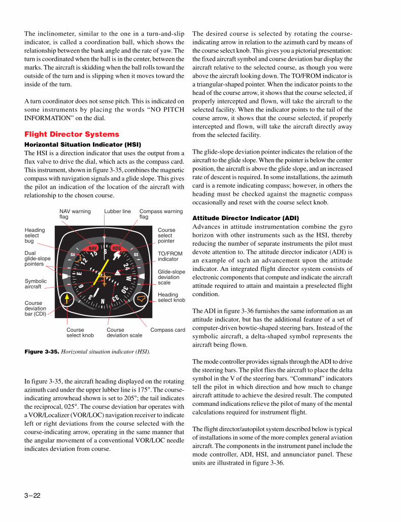
Flight Director SystemsHorizontal Situation Indicator (HSI)The HSI is a direction indicator that uses the output from aflux valve to drive the dial, which acts as the compass card.This instrument, shown in figure 3-35, combines the magneticcompass with navigation signals and a glide slope. This givesthe pilot an indication of the location of the aircraft withrelationship to the chosen course.
In figure 3-35, the aircraft heading displayed on the rotatingazimuth card under the upper lubber line is 175°. The course-indicating arrowhead shown is set to 205°; the tail indicatesthe reciprocal, 025°. The course deviation bar operates witha VOR/Localizer (VOR/LOC) navigation receiver to indicateleft or right deviations from the course selected with thecourse-indicating arrow, operating in the same manner thatthe angular movement of a conventional VOR/LOC needleindicates deviation from course.
The desired course is selected by rotating the course-indicating arrow in relation to the azimuth card by means ofthe course select knob. This gives you a pictorial presentation:the fixed aircraft symbol and course deviation bar display theaircraft relative to the selected course, as though you wereabove the aircraft looking down. The TO/FROM indicator isa triangular-shaped pointer. When the indicator points to thehead of the course arrow, it shows that the course selected, ifproperly intercepted and flown, will take the aircraft to theselected facility. When the indicator points to the tail of thecourse arrow, it shows that the course selected, if properlyintercepted and flown, will take the aircraft directly awayfrom the selected facility.
The glide-slope deviation pointer indicates the relation of theaircraft to the glide slope. When the pointer is below the centerposition, the aircraft is above the glide slope, and an increasedrate of descent is required. In some installations, the azimuthcard is a remote indicating compass; however, in others theheading must be checked against the magnetic compassoccasionally and reset with the course select knob.
Attitude Director Indicator (ADI)Advances in attitude instrumentation combine the gyrohorizon with other instruments such as the HSI, therebyreducing the number of separate instruments the pilot mustdevote attention to. The attitude director indicator (ADI) isan example of such an advancement upon the attitudeindicator. An integrated flight director system consists ofelectronic components that compute and indicate the aircraftattitude required to attain and maintain a preselected flightcondition.
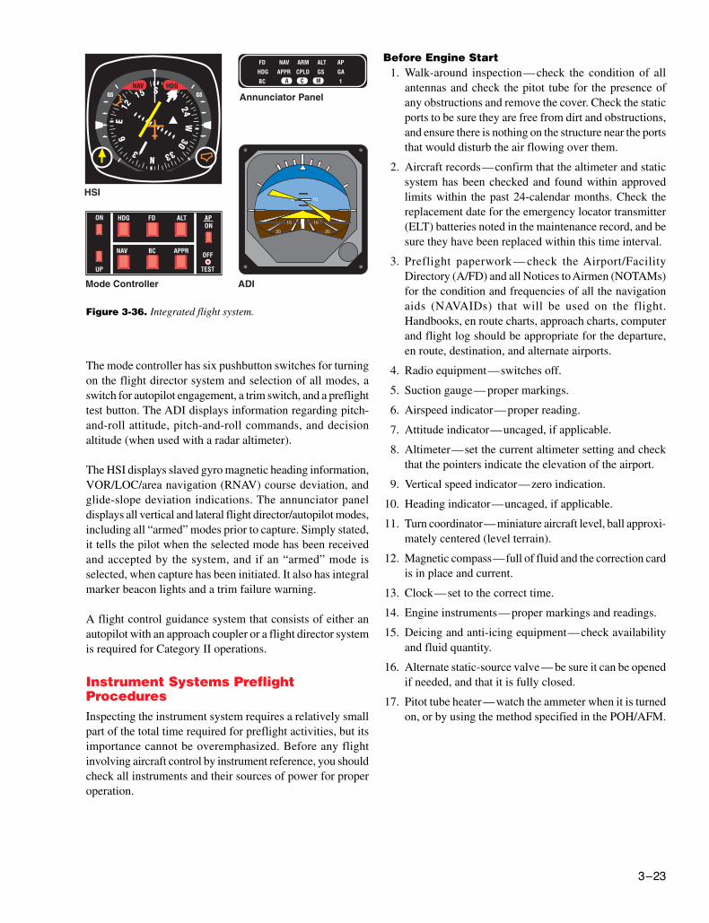
The ADI in figure 3-36 furnishes the same information as anattitude indicator, but has the additional feature of a set ofcomputer-driven bowtie-shaped steering bars. Instead of thesymbolic aircraft, a delta-shaped symbol represents theaircraft being flown.
The mode controller provides signals through the ADI to drivethe steering bars. The pilot flies the aircraft to place the deltasymbol in the V of the steering bars. “Command” indicatorstell the pilot in which direction and how much to changeaircraft attitude to achieve the desired result. The computedcommand indications relieve the pilot of many of the mentalcalculations required for instrument flight.
The flight director/autopilot system described below is typicalof installations in some of the more complex general aviationaircraft. The components in the instrument panel include themode controller, ADI, HSI, and annunciator panel. Theseunits are illustrated in figure 3-36.
Figure 3-35. Horizontal situation indicator (HSI).
3–23
The mode controller has six pushbutton switches for turningon the flight director system and selection of all modes, aswitch for autopilot engagement, a trim switch, and a preflighttest button. The ADI displays information regarding pitch-and-roll attitude, pitch-and-roll commands, and decisionaltitude (when used with a radar altimeter).
The HSI displays slaved gyro magnetic heading information,VOR/LOC/area navigation (RNAV) course deviation, andglide-slope deviation indications. The annunciator paneldisplays all vertical and lateral flight director/autopilot modes,including all “armed” modes prior to capture. Simply stated,it tells the pilot when the selected mode has been receivedand accepted by the system, and if an “armed” mode isselected, when capture has been initiated. It also has integralmarker beacon lights and a trim failure warning.
A flight control guidance system that consists of either anautopilot with an approach coupler or a flight director systemis required for Category II operations.
Instrument Systems PreflightProceduresInspecting the instrument system requires a relatively smallpart of the total time required for preflight activities, but itsimportance cannot be overemphasized. Before any flightinvolving aircraft control by instrument reference, you shouldcheck all instruments and their sources of power for properoperation.
Before Engine Start1. Walk-around inspection—check the condition of all
antennas and check the pitot tube for the presence ofany obstructions and remove the cover. Check the staticports to be sure they are free from dirt and obstructions,and ensure there is nothing on the structure near the portsthat would disturb the air flowing over them.
2. Aircraft records—confirm that the altimeter and staticsystem has been checked and found within approvedlimits within the past 24-calendar months. Check thereplacement date for the emergency locator transmitter(ELT) batteries noted in the maintenance record, and besure they have been replaced within this time interval.
3. Preflight paperwork — check the Airport/FacilityDirectory (A/FD) and all Notices to Airmen (NOTAMs)for the condition and frequencies of all the navigationaids (NAVAIDs) that will be used on the flight.Handbooks, en route charts, approach charts, computerand flight log should be appropriate for the departure,en route, destination, and alternate airports.
4. Radio equipment—switches off.
5. Suction gauge— proper markings.
6. Airspeed indicator—proper reading.
7. Attitude indicator—uncaged, if applicable.
8. Altimeter—set the current altimeter setting and checkthat the pointers indicate the elevation of the airport.
9. Vertical speed indicator—zero indication.
10. Heading indicator—uncaged, if applicable.
11. Turn coordinator— miniature aircraft level, ball approxi-mately centered (level terrain).
12. Magnetic compass—full of fluid and the correction cardis in place and current.
13. Clock—set to the correct time.
14. Engine instruments—proper markings and readings.
15. Deicing and anti-icing equipment—check availabilityand fluid quantity.
16. Alternate static-source valve — be sure it can be openedif needed, and that it is fully closed.
17. Pitot tube heater—watch the ammeter when it is turnedon, or by using the method specified in the POH/AFM.
Figure 3-36. Integrated flight system.
3–24
After Engine Start1. When you turn the master switch on— listen to the
gyros as they spin up. Any hesitation or unusual noisesshould be investigated before flight.
2. Suction gauge or electrical indicators— check the sourceof power for the gyro instruments. The suction developedshould be appropriate for the instruments in that parti-cular aircraft. If the gyros are electrically driven, checkthe generators and inverters for proper operation.
3. Magnetic compass—check the card for freedom ofmovement and confirm the bowl is full of fluid. Deter-mine compass accuracy by comparing the indicatedheading against a known heading (runway heading)while the airplane is stopped or taxiing straight. Remoteindicating compasses should also be checked againstknown headings. Note the compass card correction forthe takeoff runway heading.
4. Heading indicator— allow 5 minutes after startingengines for the gyro to spin up. Before taxiing, or whiletaxiing straight, set the heading indicator to correspondwith the magnetic compass heading. A slaved gyrocompass should be checked for slaving action and itsindications compared with those of the magneticcompass.
5. Attitude indicator—allow the same time as noted abovefor gyros to spin up. If the horizon bar erects to thehorizontal position and remains at the correct positionfor the attitude of the airplane, or if it begins to vibrateafter this attitude is reached and then slowly stopsvibrating altogether, the instrument is operating properly.
6. Altimeter—with the altimeter set to the current reportedaltimeter setting, note any variation between the knownfield elevation and the altimeter indication. If thevariation is on the order of 75 feet, the accuracy of thealtimeter is questionable and the problem should bereferred to a repair station for evaluation and possiblecorrection. Because the elevation of the ramp or hangararea might differ significantly from field elevation, re-check when in the runup area if the error exceeds 75feet. When no altimeter setting is available, set thealtimeter to the published field elevation during thepreflight instrument check.
7. Vertical speed indicator—the instrument should readzero. If it does not, tap the panel gently. If it stays off thezero reading and is not adjustable, the ground indicationwill have to be interpreted as the zero position in flight.
8. Carburetor heat—check for proper operation and returnto cold position.
9. Engine instruments—check for proper readings.
10. Radio equipment— check for proper operation and setas desired.
11. Deicing and anti-icing equipment—check operation.
Taxiing and Takeoff1. Turn coordinator—during taxi turns, check the miniature
aircraft for proper turn indications. The ball should movefreely. The ball should move opposite to the direction ofturns. The turn instrument should indicate in the directionof the turn. While taxiing straight, the miniature aircraftshould be level.
2. Heading indicator—before takeoff, recheck the headingindicator. If your magnetic compass and deviation cardare accurate, the heading indicator should show the knowntaxiway or runway direction when the airplane is alignedwith them (within 5°).
3. Attitude indicator—if the horizon bar fails to remain inthe horizontal position during straight taxiing, or tips inexcess of 5° during taxi turns, the instrument is unreliable.Adjust the miniature aircraft with reference to the horizonbar for the particular airplane while on the ground. Forsome tricycle-gear airplanes, a slightly nose-low attitudeon the ground will give a level flight attitude at normalcruising speed.
Engine Shut DownWhen shutting down the engine, note any abnormal instru-ment indications.