Embed Size (px)
Citation preview
Pag. 1
Render Image Srl Via Roma 101/5 - 30020 QUARTO D’ALTINO VE - ITALIA
Tel. +39 0422.823977 Fax +39 0422.782814 www.masterchef-cad.it www.masterchef-cad.com - Email [email protected]
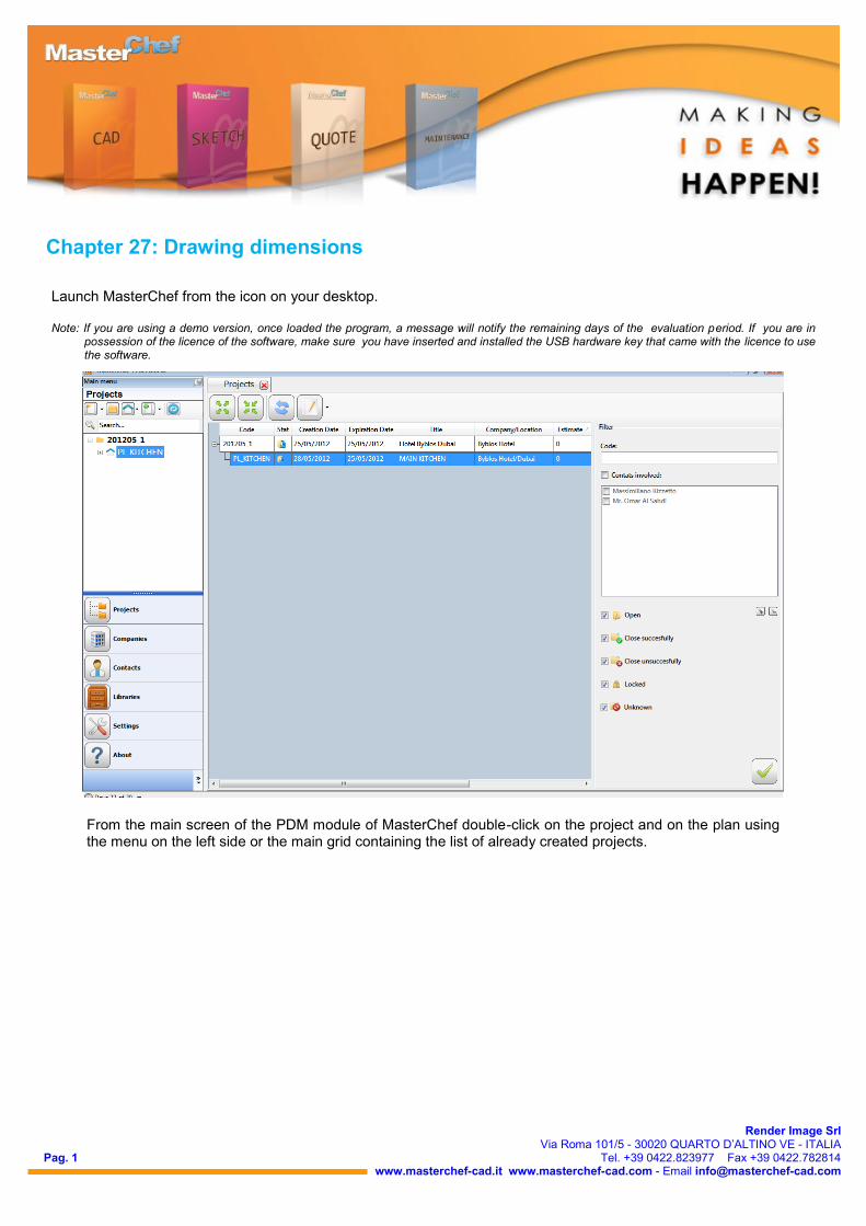
From the main screen of the PDM module of MasterChef double-click on the project and on the plan using the menu on the left side or the main grid containing the list of already created projects.
Launch MasterChef from the icon on your desktop. Note: If you are using a demo version, once loaded the program, a message will notify the remaining days of the evaluation period. If you are in
possession of the licence of the software, make sure you have inserted and installed the USB hardware key that came with the licence to use the software.
Chapter 27: Drawing dimensions
Pag. 2
Render Image Srl Via Roma 101/5 - 30020 QUARTO D’ALTINO VE - ITALIA
Tel. +39 0422.823977 Fax +39 0422.782814 www.masterchef-cad.it www.masterchef-cad.com - Email [email protected]
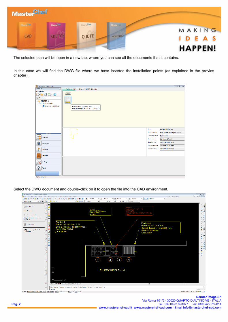
The selected plan will be open in a new tab, where you can see all the documents that it contains. In this case we will find the DWG file where we have inserted the installation points (as explained in the previos chapter).
Select the DWG document and double-click on it to open the file into the CAD environment.
Pag. 3
Render Image Srl Via Roma 101/5 - 30020 QUARTO D’ALTINO VE - ITALIA
Tel. +39 0422.823977 Fax +39 0422.782814 www.masterchef-cad.it www.masterchef-cad.com - Email [email protected]
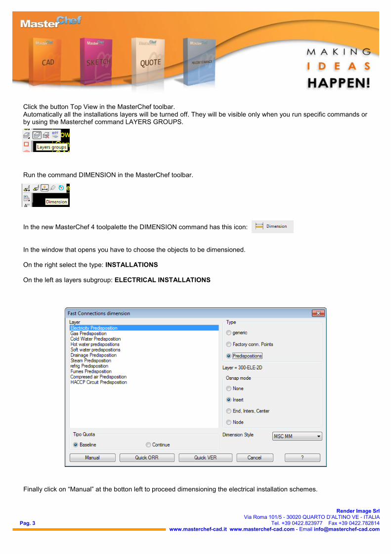
Click the button Top View in the MasterChef toolbar. Automatically all the installations layers will be turned off. They will be visible only when you run specific commands or by using the Masterchef command LAYERS GROUPS.
Run the command DIMENSION in the MasterChef toolbar.
In the new MasterChef 4 toolpalette the DIMENSION command has this icon: In the window that opens you have to choose the objects to be dimensioned. On the right select the type: INSTALLATIONS On the left as layers subgroup: ELECTRICAL INSTALLATIONS
Finally click on “Manual” at the botton left to proceed dimensioning the electrical installation schemes.
Pag. 4
Render Image Srl Via Roma 101/5 - 30020 QUARTO D’ALTINO VE - ITALIA
Tel. +39 0422.823977 Fax +39 0422.782814 www.masterchef-cad.it www.masterchef-cad.com - Email [email protected]
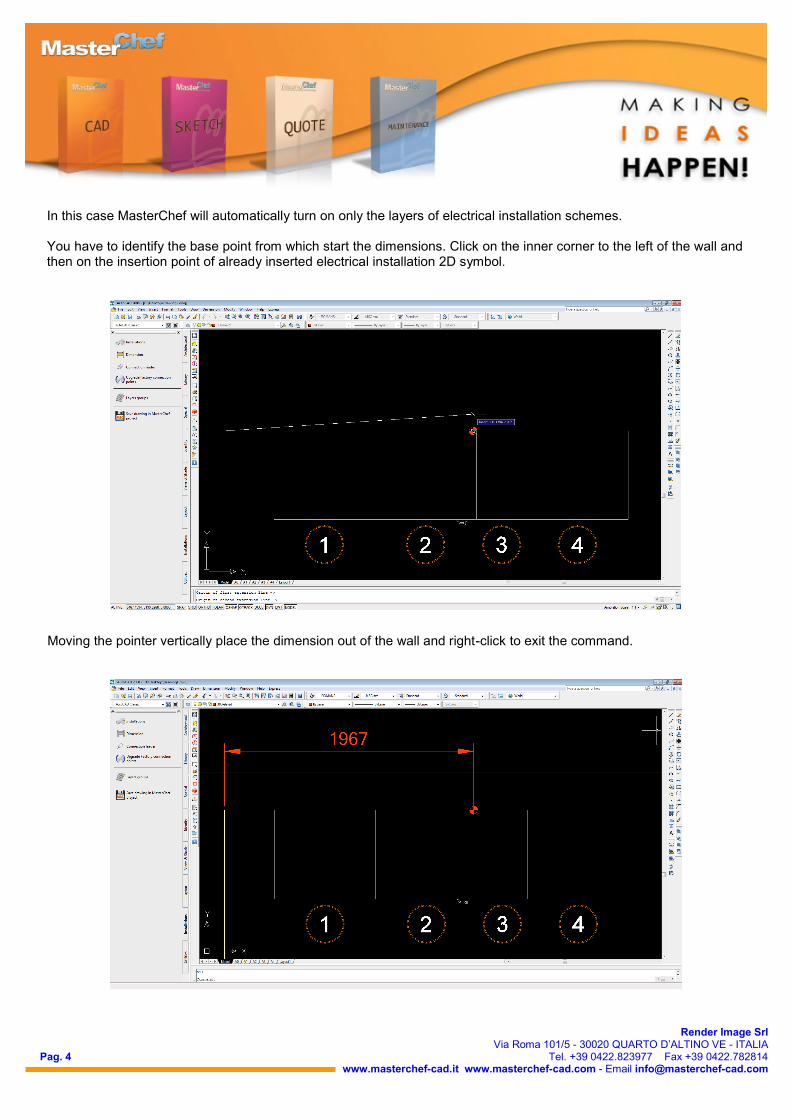
In this case MasterChef will automatically turn on only the layers of electrical installation schemes. You have to identify the base point from which start the dimensions. Click on the inner corner to the left of the wall and then on the insertion point of already inserted electrical installation 2D symbol.
Moving the pointer vertically place the dimension out of the wall and right-click to exit the command.
Pag. 5
Render Image Srl Via Roma 101/5 - 30020 QUARTO D’ALTINO VE - ITALIA
Tel. +39 0422.823977 Fax +39 0422.782814 www.masterchef-cad.it www.masterchef-cad.com - Email [email protected]
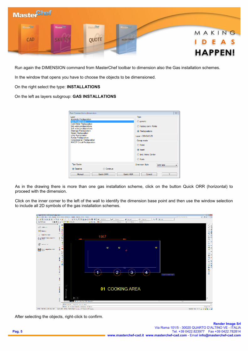
Run again the DIMENSION command from MasterChef toolbar to dimension also the Gas installation schemes. In the window that opens you have to choose the objects to be dimensioned. On the right select the type: INSTALLATIONS On the left as layers subgroup: GAS INSTALLATIONS
As in the drawing there is more than one gas installation scheme, click on the button Quick ORR (horizontal) to proceed with the dimension. Click on the inner corner to the left of the wall to identify the dimension base point and then use the window selection to include all 2D symbols of the gas installation schemes.
After selecting the objects, right-click to confirm.
Pag. 6
Render Image Srl Via Roma 101/5 - 30020 QUARTO D’ALTINO VE - ITALIA
Tel. +39 0422.823977 Fax +39 0422.782814 www.masterchef-cad.it www.masterchef-cad.com - Email [email protected]
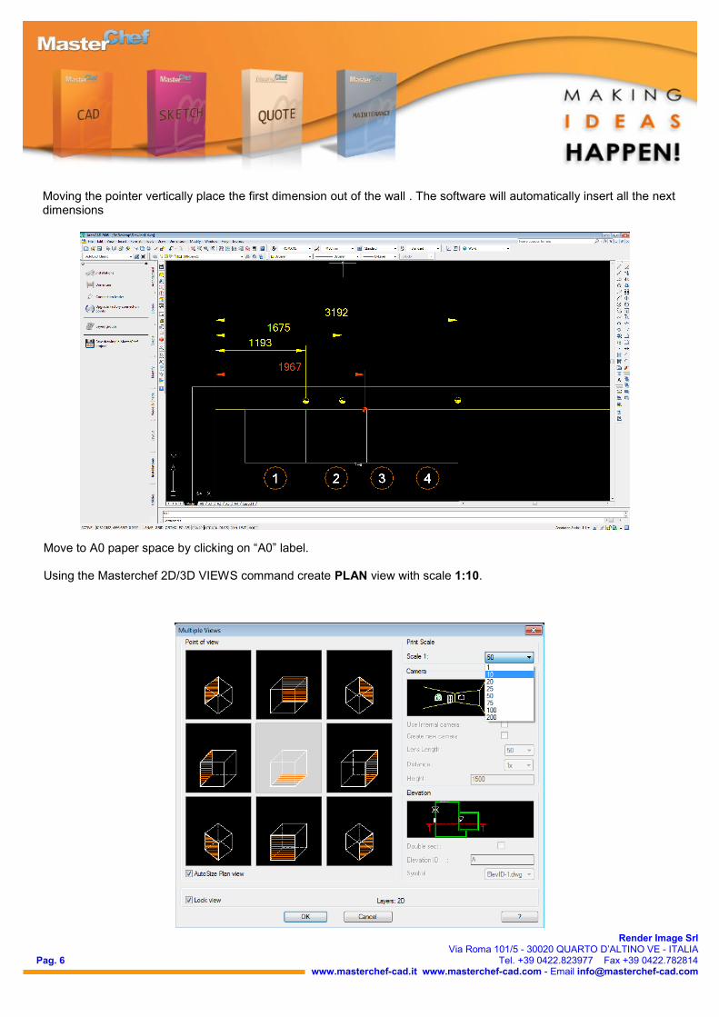
Moving the pointer vertically place the first dimension out of the wall . The software will automatically insert all the next dimensions
Move to A0 paper space by clicking on “A0” label. Using the Masterchef 2D/3D VIEWS command create PLAN view with scale 1:10.
Pag. 7
Render Image Srl Via Roma 101/5 - 30020 QUARTO D’ALTINO VE - ITALIA
Tel. +39 0422.823977 Fax +39 0422.782814 www.masterchef-cad.it www.masterchef-cad.com - Email [email protected]
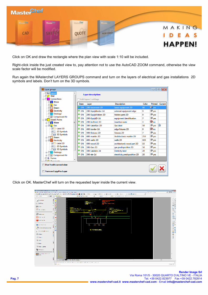
Click on OK and draw the rectangle where the plan view with scale 1:10 will be included. Right-click inside the just created view to, pay attention not to use the AutoCAD ZOOM command, otherwise the view scale factor will be modified. Run again the MAsterchef LAYERS GROUPS command and turn on the layers of electrical and gas installations 2D symbols and labels. Don’t turn on the 3D symbols.
Click on OK. MasterChef will turn on the requested layer inside the current view.
Pag. 8
Render Image Srl Via Roma 101/5 - 30020 QUARTO D’ALTINO VE - ITALIA
Tel. +39 0422.823977 Fax +39 0422.782814 www.masterchef-cad.it www.masterchef-cad.com - Email [email protected]
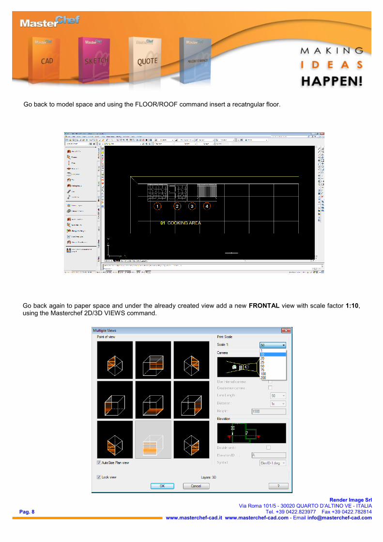
Go back again to paper space and under the already created view add a new FRONTAL view with scale factor 1:10, using the Masterchef 2D/3D VIEWS command.
Go back to model space and using the FLOOR/ROOF command insert a recatngular floor.
Pag. 9
Render Image Srl Via Roma 101/5 - 30020 QUARTO D’ALTINO VE - ITALIA
Tel. +39 0422.823977 Fax +39 0422.782814 www.masterchef-cad.it www.masterchef-cad.com - Email [email protected]
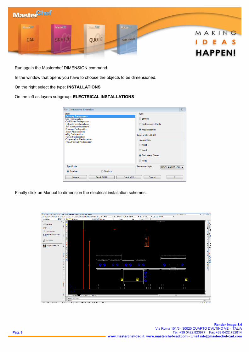
Run again the Masterchef DIMENSION command. In the window that opens you have to choose the objects to be dimensioned. On the right select the type: INSTALLATIONS On the left as layers subgroup: ELECTRICAL INSTALLATIONS
Finally click on Manual to dimension the electrical installation schemes.