Embed Size (px)
Citation preview
31
CHAPTER – 2
VSI FED INDUCTION MOTOR DRIVE
2.1 INTRODUCTION
DC motors have been used during the last century in industries for variable speed
applications, because its flux and torque can be controlled easily by means of changing the
field and armature currents respectively. Furthermore, operation in the four quadrants of the
torque speed plane including temporary standstill was achieved. Almost for a century,
induction motor has been the workhorse of industry due to its robustness, low cost high
efficiency and less maintenance. The induction motors were mainly used for essentially
constant speed applications because of the unavailability of the variable- frequency voltage
supply. The advancement of power electronics has made it possible to vary the frequency of
the voltage supplies relatively easy, thus extending the use of the induction motor in variable
speed drive applications. But due to the inherent coupling of flux and torque components in
induction motor, it could not provide the torque performance as good as the DC motor.
In AC grid connected motor drives, a rectifier, usually a common diode bridge
providing a pulsed DC voltage from the mains is required. Although the basic circuit for an
inverter may seem simple, accurately switching these devices provides a number of
challenges. The most common switching technique is called Pulse Width Modulation
(PWM). PWM is a powerful technique for controlling analog circuits with a processor’s
digital outputs. PWM is employed in a wide variety of applications like UPS, electric drives,
HVDC reactive power compensators in power systems, ranging from measurement and
communications to power control and conversion. In AC motor drives, PWM inverters make
it possible to control both frequency and magnitude of the voltage and current applied to a
motor. As a result, PWM inverter-powered motor drives are more variable and offer in a
wide range better efficiency and higher performance when compared to fixed frequency
motor drives. The energy, which is delivered by the PWM inverter to the AC motor, is
controlled by PWM signals applied to the gates of the power switches at different times for
varying durations to produce the desired output waveform. To improve the quality of the
product, variable speed is required, for that step less speed control is required. Depending on
the type of load and the type of speed different methods are adopted for speed control of
32
motors. For step less speed control below and above the rated speed with high torque and to
avoid the harmonics, the PWM inverter fed induction motor control is the best suitable one.
The block diagram of VSI fed Induction Motor is shown in Fig 2.1.
AC supply
Fig2.1 Block diagram of VSI fed Induction Motor
2.2 THREE PHASE PWM INVERTER
The PWM inverter has to generate nearly sinusoidal current, which can control the
voltage and current with 120 degrees difference in each phase. The controlling signals of
three-phase PWM inverters have many pattern controls. The operation of three-phase
inverter can be defined in eight modes, which shows the status of each switch in each
operations mode. In inverter operation, the necessary phase-leg-short is naturally realized
through anti-parallel diodes in the three-phase bridge. Accordingly, the same gate pulses as
in the conventional VSI can be applied. On the other hand, the switch on the DC link must
actively operate.
The recent advancement in power electronics has initiated to improve the level of the
inverter instead of increasing the size of the filter. In multilevel inverter, design involves
parallel connection of the inverter. For these redundant switching a space vector modulation
is needed which is based on vector selection in dq stationary reference frame. For a multi
level system either space vector modulation or sinusoidal triangle modulation may be taken.
However space vector modulation is having more advantages due to low harmonic
production.
The performance of the multi level inverter is better than the classical inverter. The
total harmonic distortion of the classical inverter is very high. The diode clamped inverter
provides multiple voltage levels from a series capacitor bank. The voltage across the switches
is only half of the DC bus voltage. These features effectively double the power rating of
Single phase Rectifier
Three phase
INVERTER
Induction Motor drive
33
voltage source inverter to the given semiconductor device. The total harmonic distortion is
analyzed between multilevel inverter and other classical inverters.
Field oriented control (FOC) of induction motor was introduced which has opened a
new horizon to the induction motor applications. The method, which uses frame, has
transformed the performance of induction motor similar to that of the DC motor. The
implementation of this system however is complicated and furthermore FOC, in particularly
indirect method which is widely used, is known to be highly sensitive to parameter variations
due to the feed-forward structure of its control system. In the DTC drive, flux linkage and
electromagnetic torque are controlled directly and independently by the selection of optimum
inverter switching modes. The required optimal switching voltage vectors can be selected by
using a so called optimum switching voltage vector look up table. In the present work an
attempt is made to simulate DTC system.
2.3 SIMULATION RESULTS
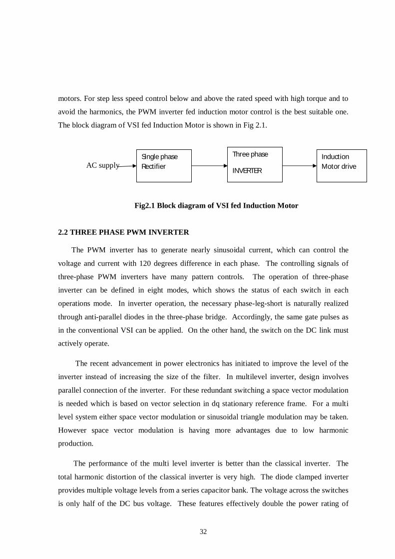
The circuit of six switch three phase inverter system is shown in Figure 2.2. In three-
phase inverter fed drive system, AC is converted into DC using uncontrolled rectifier. DC is
converted into variable voltage variable frequency AC using three-phase PWM inverter. The
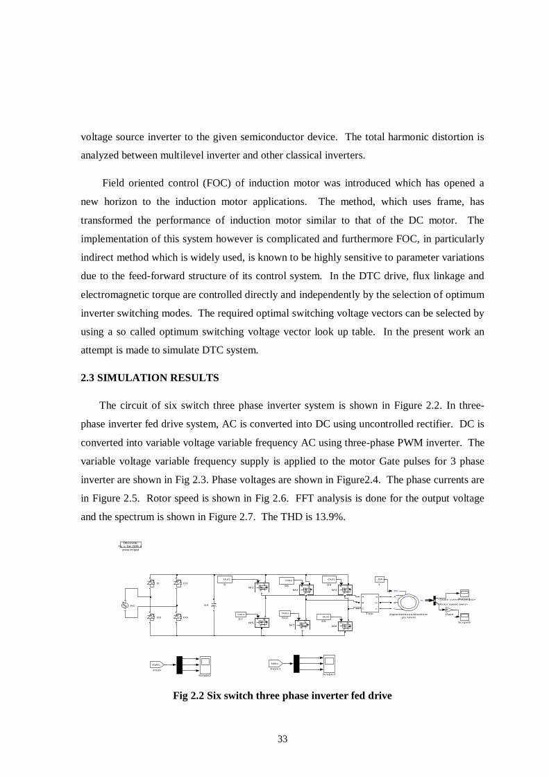
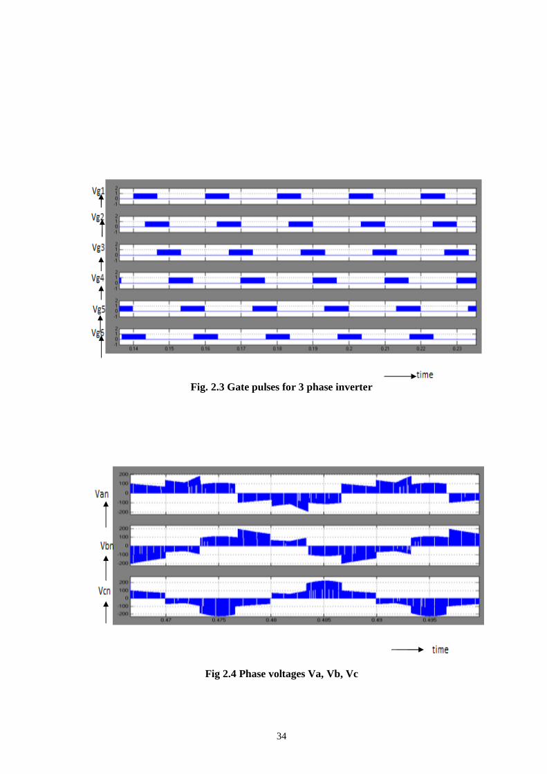
variable voltage variable frequency supply is applied to the motor Gate pulses for 3 phase
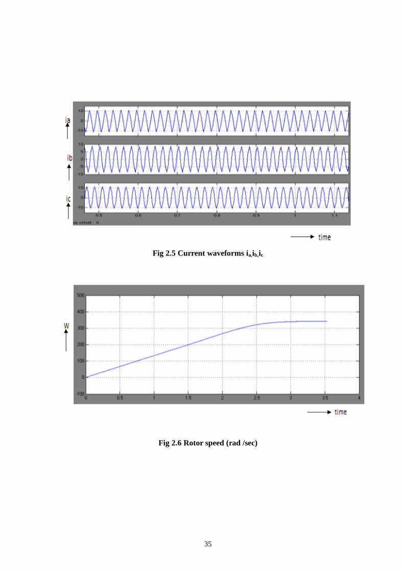
inverter are shown in Fig 2.3. Phase voltages are shown in Figure2.4. The phase currents are
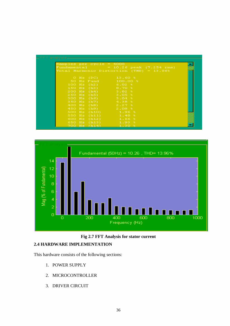
in Figure 2.5. Rotor speed is shown in Fig 2.6. FFT analysis is done for the output voltage
and the spectrum is shown in Figure 2.7. The THD is 13.9%.
Fig 2.2 Six switch three phase inverter fed drive
Discrete,Ts = 5e-006 s.
pow ergui
A
B
C
a
b
c
Thre
Scope5
Scope3Scope2
Scope1
Out1
S9
Out1
S7
Out1
S6
Out1
S5
S4
Out1
S10
Out1
S
g DS
M7
g D
S
M6
g DS
M5
g D
S
M4
g D
S
M3
g DS
M1
-K-
Gain
Iabc
From1
Vabc
From
D3D2
D1D
Tm
m
A
B
C
Asynchronous Machinepu Units
AC
-.04
1
<Rotor speed (wm)>
<Stator current is_a (pu)>
34
Fig. 2.3 Gate pulses for 3 phase inverter
Fig 2.4 Phase voltages Va, Vb, Vc
35
Fig 2.5 Current waveforms ia,ib,ic
Fig 2.6 Rotor speed (rad /sec)
36
Fig 2.7 FFT Analysis for stator current
2.4 HARDWARE IMPLEMENTATION
This hardware consists of the following sections:
1. POWER SUPPLY
2. MICROCONTROLLER
3. DRIVER CIRCUIT

37
2.4.1 POWER SUPPLY
Figure 2.8 Power circuit
A step- down transformer (230/15)V is used to give input supply to the power circuit.
The 15V AC input is rectified into 15V pulsating DC with the help of full bridge rectifier
circuit. The ripples in the pulsating DC are removed and pure DC is obtained by using a
capacitor filter. The positive terminal of the capacitor is connected to the input pin of the
7812 regulator for voltage regulation. An output voltage of 12V is obtained from the output
pin of 7805 which is fed as the supply to the micro controller. From the same output pin of
the 7805, a LED is connected in series with the resistor to indicate that the power is ON.
2.4.2 AT89C2051 MICROCONTROLLER
The AT89C2051 is a low voltage, high performance CMOS 8-bit microcomputer
with 2K bytes of flash, programmable and erasable read only memory. The device is
manufactured using ATMEL high-density nonvolatile memory technology and is compatible
with the industry standard MCS-51 instruction set. By combining a versatile 8-bit CPU with
flash on a monolithic chip, the Atmel AT89C2051 is a powerful microcomputer, which
provides a highly flexible and cost effective solution to many embedded control applications.
The AT89C2051 provides the standard following features: 2K bytes of flash, 128 bytes of
RAM, 15 I/O lines, two 16-bit timers/counters, a five vector two level; interrupt architecture,
a full duplex serial port, a precision analog comparator, on-chip oscillator and clock circuitry.
In addition, the AT89C2051 is designed with static logic operation down to zero frequency
and supports two software selectable powers saving down to zero frequency and supports
two software selectable power saving modes. The idle mode stops the CPU while allowing
38
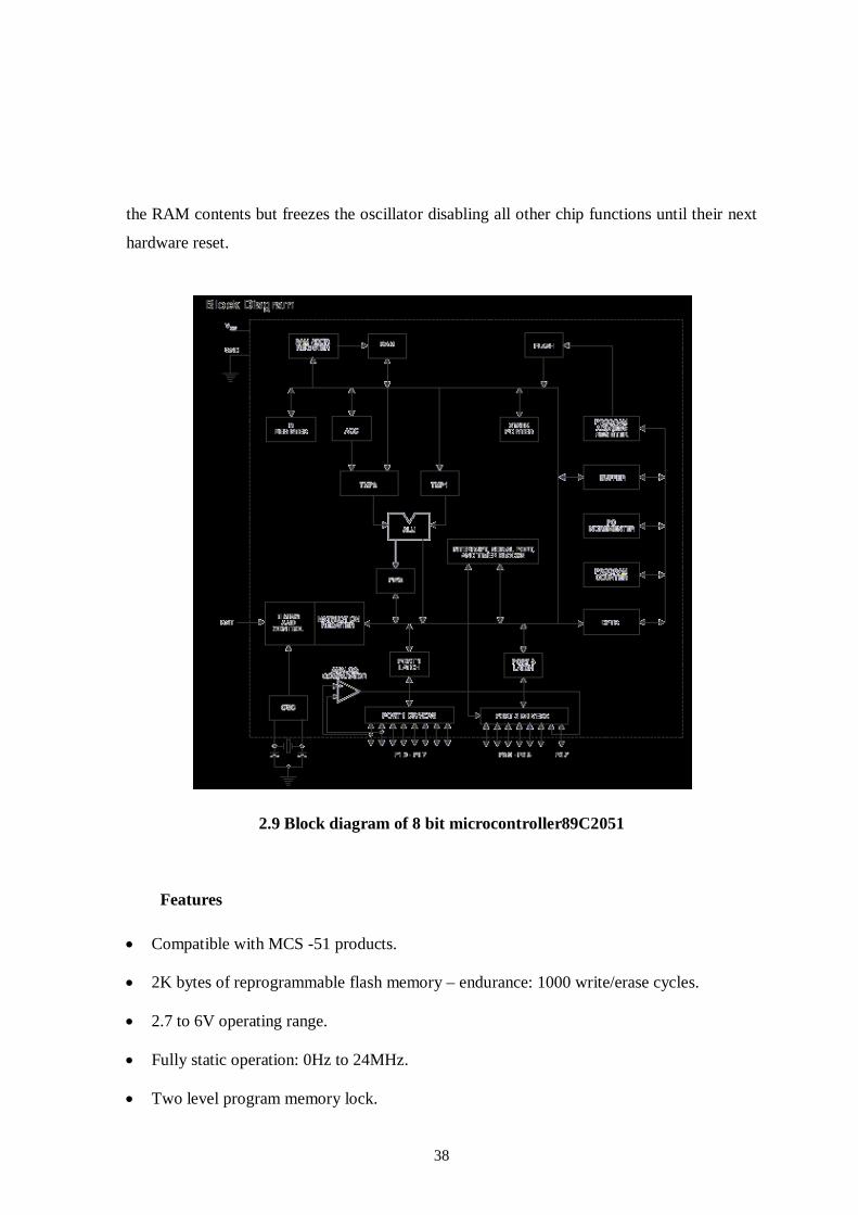
the RAM contents but freezes the oscillator disabling all other chip functions until their next
hardware reset.
2.9 Block diagram of 8 bit microcontroller89C2051
Features
Compatible with MCS -51 products.
2K bytes of reprogrammable flash memory – endurance: 1000 write/erase cycles.
2.7 to 6V operating range.
Fully static operation: 0Hz to 24MHz.
Two level program memory lock.
39
128χ8-bit internal RAM.
15 programmable I/O lines.
Two 16-bit timers/counters.
Six interrupt sources.
Programmable serial UART channel.
Direct LED drive outputs.
On-chip analog comparator.
Low-power idle and power-down modes.
Green (Pb/Halide-free) packaging option
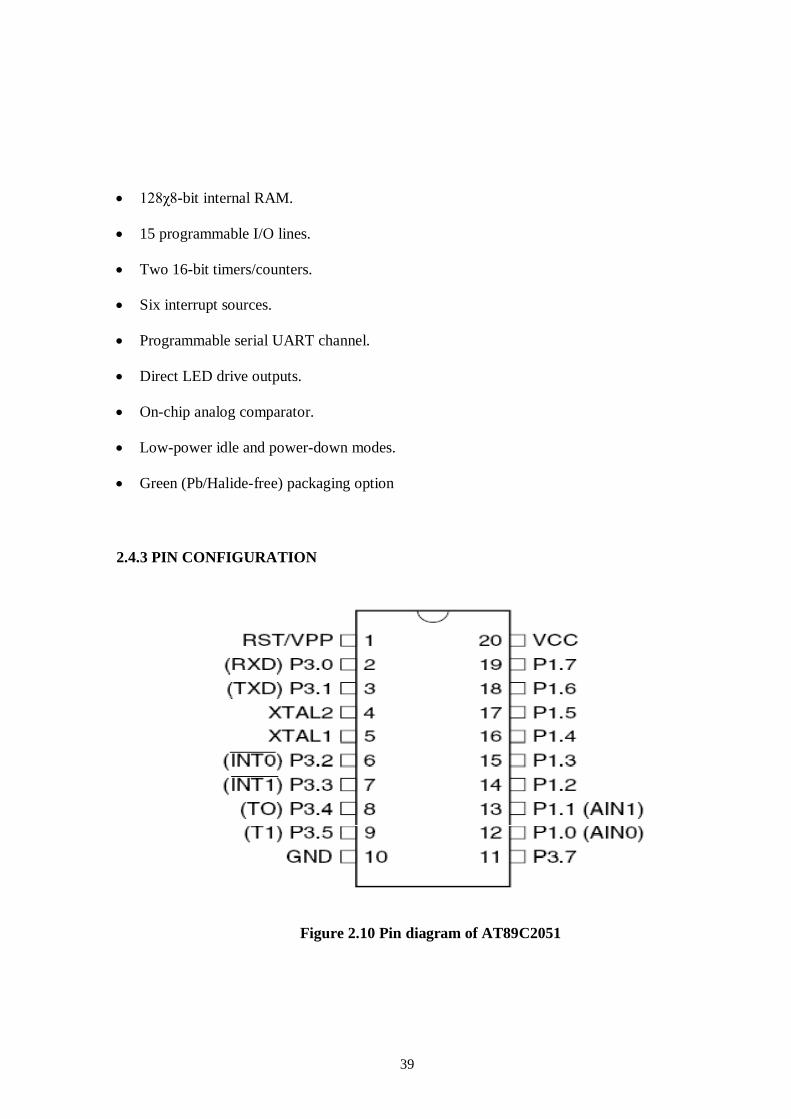
2.4.3 PIN CONFIGURATION
Figure 2.10 Pin diagram of AT89C2051

40
OPERATING DESCRIPTION
The detailed description of AT89C51 includes
Memory map and register.
Timer/counter
Other information
Flash memory
The AT89C51 has separate address paces for program and data memory. The
program and data memory can be up to 64KB long. The lower 4K program memory can
reside on-chip. The AT89C51 has 129 bytes of on-chip RAM plus number of special
function registers. The lower 128 bytes can be accessed either by direct addressing or by
indirect addressing.
The lower 128 bytes of RAM can be divided into three segments as
Register banks 0-3
Bit addressable area
Scratch pad area
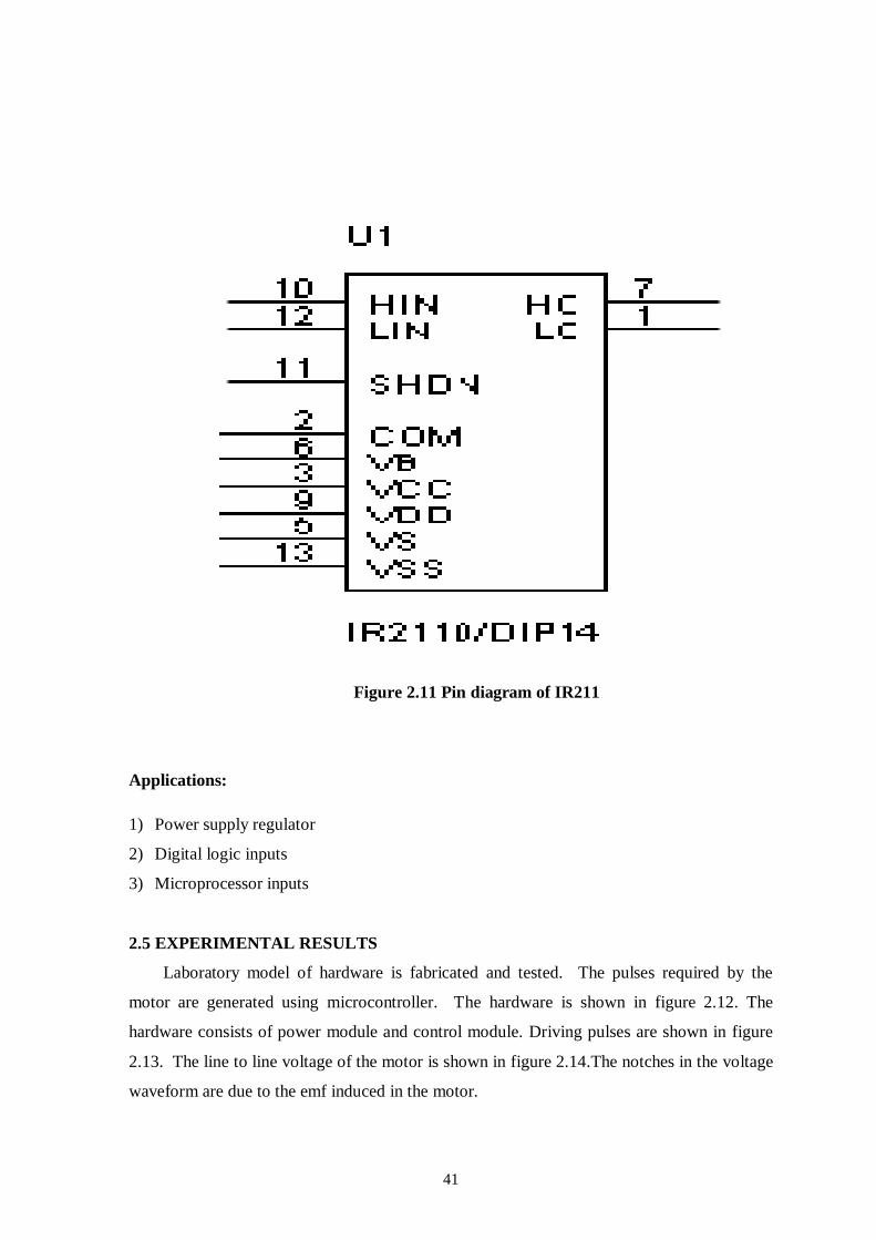
2.4.4 DRIVER UNIT
The IR2110 is a high voltage, high speed power MOSFET driver with independent
high and low side referenced output channels. It is fully operational to +500V or +600V and
tolerant to negative transient voltage dv/dt immune. Logic inputs are compatible with
standard CMOS or LSTTL output, down to 3.3 V logic. The output drivers feature a high
pulse current buffer stage designed for minimum driver cross-conduction.
Propagation delays are matched to simplify the use in high frequency applications. The
floating channel can be used to drive an N-channel power MOSFET or IGBT in the high side
configuration which operates up to 500 to 600 volts.
41
Figure 2.11 Pin diagram of IR211
Applications:
1) Power supply regulator
2) Digital logic inputs
3) Microprocessor inputs
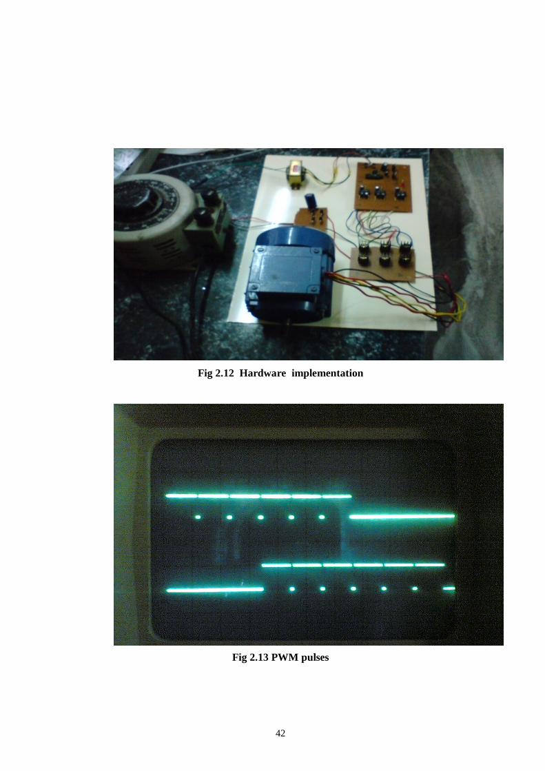
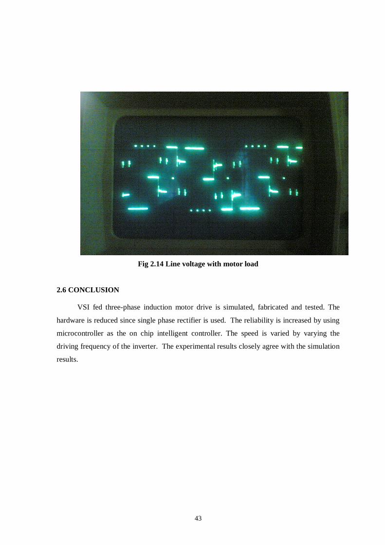
2.5 EXPERIMENTAL RESULTS
Laboratory model of hardware is fabricated and tested. The pulses required by the
motor are generated using microcontroller. The hardware is shown in figure 2.12. The
hardware consists of power module and control module. Driving pulses are shown in figure
2.13. The line to line voltage of the motor is shown in figure 2.14.The notches in the voltage
waveform are due to the emf induced in the motor.
42
Fig 2.12 Hardware implementation
Fig 2.13 PWM pulses
43
Fig 2.14 Line voltage with motor load
2.6 CONCLUSION
VSI fed three-phase induction motor drive is simulated, fabricated and tested. The
hardware is reduced since single phase rectifier is used. The reliability is increased by using
microcontroller as the on chip intelligent controller. The speed is varied by varying the
driving frequency of the inverter. The experimental results closely agree with the simulation
results.