Embed Size (px)
Citation preview

Chapter-2
METHODS OF TESTING CIRCUIT-BREAKERS: A REVIEW
Short-circuit tests are conducted to prove the ratings of the circuit-breakers. The
following short-circuit tests are conducted on circuit-breakers;
(1) Breaking capacity test
(2) Making capacity
(3) Duty cycle test
(4) Short Time Current Test
Short-circuit tests can be performed either by direct testing or indirect testing
methods.
2.1 Direct Testing
IEC Standards definition of direct test is as follows:
“ A test in which the applied voltage, the current and the transient and power-
frequency recovery voltages are all obtained from a circuit having a single power
source, which may be a power system or special alternators as used in short-circuit
testing stations or a combination of both”[25].
A direct test is one where a three phase circuit-breaker is tested, on a three phase
system, and at a short circuit MVA level equal to its full rating. In other words this
is a test where a three phase circuit-breaker is tested on a 3-phase circuit at full
current and full voltage. It should be obvious that testing a circuit-breaker under the
same conditions at which it is going to be applied is the ultimate demonstration for
its capability and naturally, whenever possible, this should be the preferred method of
test. In direct testing, the circuit-breaker is tested under the conditions which actually
exist on power systems and it is subjected to transient recovery voltage (TRV) which
is expected in practical situations[l],[3].
In direct testing, the short circuit tests are conducted in short circuit testing stations
and are mainly to prove the ratings of the circuit breaker. There are two types of short-
circuit testing stations:
(1) Field type testing station
In this, the tests are conducted taking power directly from the system.
9

(2) Laboratory type testing stations
It has short-circuit generators to supply power for the short-circuit testing.
The short - circuit testing stations consists of the following equipments/components:
(i) Short circuit generator
(ii) Short-circuit transformer
(iii) Master circuit-breaker
(iv) Making switch
(v) Capacitors
(vi) Resistors and reactors
In direct testing, the circuit-breaker is tested under the conditions which actually
exist on power systems. It is subjected to restriking voltage which is expected in
practical situations. Fig.2.1 shows an arrangement for direct testing. The reactor L is to
control short-circuits current. C, Ri and R2 are to adjust transient recovery voltage.
Fig.2.1 Circuit arrangement for direct testing
2.2 Necessity of Indirect Testing
Development in Electrical power transmission system requires the use of circuit-
breakers with increasing breaking capacity. At present circuit-breakers are to be
installed on 245kV to llOOkV power system with short-circuit ratings up to 120kA,
10

To test high voltage circuit-breakers, direct testing using the power system or short-
circuit alternators are not feasible. The testing of high voltage circuit-breakers of
larger capacity requires very large capacity of testing station. To increase testing plant
power is neither an economical nor a very practical solution. Even a single pole of
EHV circuit-breaker can not be tested by direct means.
The largest test facility in the world, KEMA high power laboratory, with a
maximum short-circuit power of 8400MVA and a 145kV, 31.5kA, 3-phase direct test
capability, is limited in its power to perform the direct tests. At the present time a
complete pole of SF6 circuit-breaker can consist of a single interrupting chamber with
an interrupting power above the 10GVA level. Even KEMA’S high power laboratory
can not verify the short-circuit interrupting capability by direct test methods[15],[18].
Direct testing facility available at CPRI high power laboratory in India is of
2500MVA capacity at 36/72.5kV in three phase and 1400MVA capacity, up to 245kV
in single phase for testing of circuit-breakers[Appendix-AJ.
The limitations of direct testing using the power system or short-circuit alternators
are as follows :
• High cost of installation of testing stations
• Availability of limited power for testing of high voltage and Extra high
voltage circuit-breakers
• Requires high power for testing circuit-breakers
• Flexibility of the system available is limited.
Therefore Indirect methods of testing are used for testing of large circuit-breakers.
Synthetic testing is an alternative equivalent method for testing of high voltage circuit
breakers and is accepted by the standards.
11
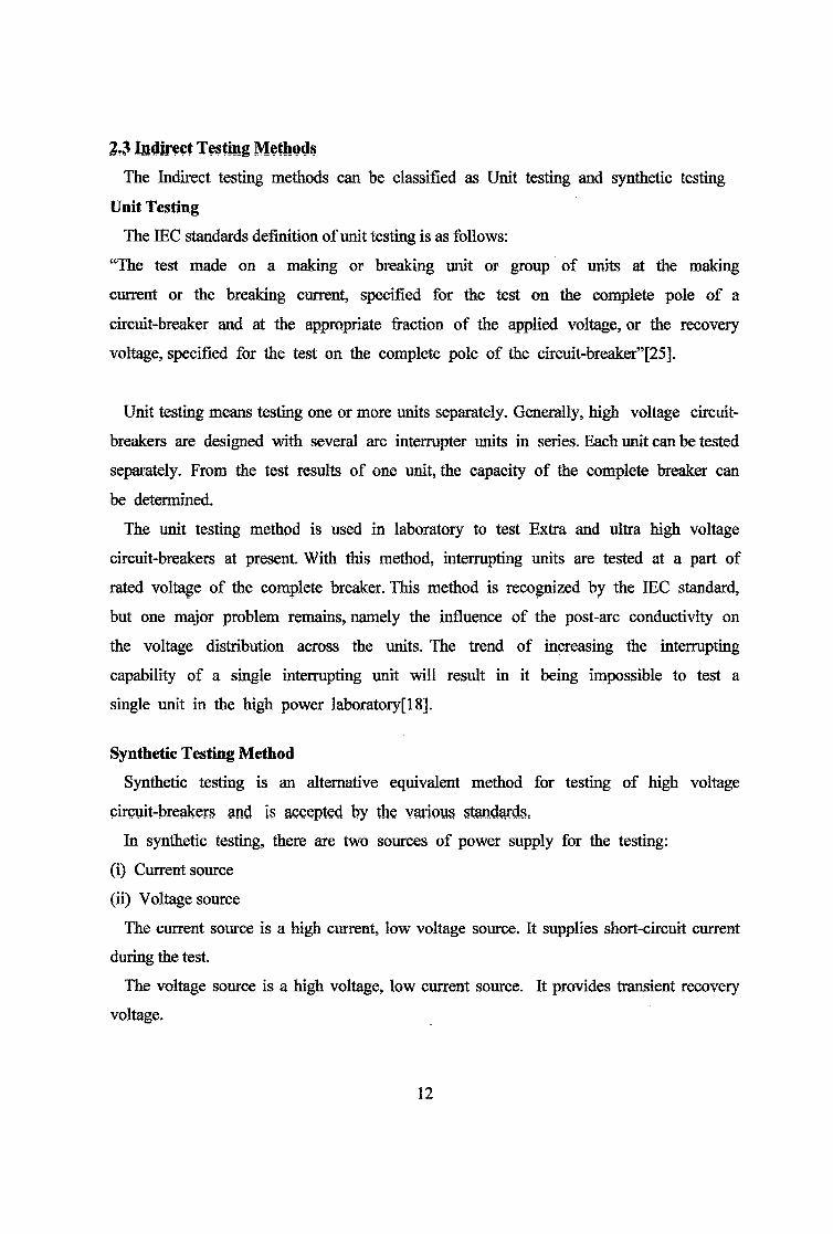
2.3 Indirect Testing Methods
The Indirect testing methods can be classified as Unit testing and synthetic testing
Unit Testing
The IEC standards definition of unit testing is as follows:
“The test made on a making or breaking unit or group of units at the making
current or the breaking current, specified for the test on the complete pole of a
circuit-breaker and at the appropriate fraction of the applied voltage, or the recovery
voltage, specified for the test on the complete pole of the circuit-breaker”[25].
Unit testing means testing one or more units separately. Generally, high voltage circuit-
breakers are designed with several arc interrupter units in series. Each unit can be tested
separately. From the test results of one unit, the capacity of the complete breaker can
be determined.
The unit testing method is used in laboratory to test Extra and ultra high voltage
circuit-breakers at present. With this method, interrupting units are tested at a part of
rated voltage of the complete breaker. This method is recognized by the IEC standard,
but one major problem remains, namely the influence of the post-arc conductivity on
the voltage distribution across the units. The trend of increasing the interrupting
capability of a single interrupting unit will result in it being impossible to test a
single unit in the high power laboratory[18].
Synthetic Testing Method
Synthetic testing is an alternative equivalent method for testing of high voltage
circuit-breakers and is accepted by the various standards.
In synthetic testing, there are two sources of power supply for the testing:
(i) Current source
(ii) Voltage source
The current source is a high current, low voltage source. It supplies short-circuit current
during the test.
The voltage source is a high voltage, low current source. It provides transient recovery
voltage.
12

2.4 Principle and Advantages of Synthetic Testing
s L
Fig. 2.3 Voltage waveforms across test Circuit-breaker
Fig.2.2 shows the basic circuit for testing circuit-breaker. When switch S is closed,
short-circuit current I flows through the breaker B and when the test breaker B begins
to open an arc voltage Va appears across the breaker terminal as shown in Fig.2.3. At
current zero when the arc is extinguished a transient voltage Ytt appears across the
breaker, whose form is determined by the generator characteristics and the circuit
constants L and C. The breaker has to withstand this transient recovery voltage if it is
to clear the circuit.
So in actual practice, during the period of main short circuit current flow, there is
comparatively small arc voltage appears across the breaker and that during the period
of transient recovery voltage very little or no current flows through the breaker.
Therefore there is no need tp use a single high power source, Instead, the current can
be supplied by a comparatively low voltage source, since the arc voltage is usually
13

very small, 1 to 3% of the rated voltage of the breaker, and the voltage can be
applied from low energy high Voltage, low current source at the point of current
zero to simulate transient recovery voltage.
Main Advantages of synthetic testing are as follows:
• The breaker can be tested for desired TRV and R.R.R.V.
• The short-circuit generator has to supply current at a relatively less voltage as
compared to direct testing.
• Both test current and test voltage can be independently varied. This gives flexibility
to test
• Very simple method of testing and can be applied to unit testing also.
• With this method a breaker of capacity (MVA) of five times that of the capacity
(MV A) of the test plant can be tested.
• Synthetic testing is of a non-destructive nature and therefore they are ideal for
development test purposes, where the ultimate limits of the device can be
explored without destroying the test model [1],
2.5 Types of synthetic test circuits
Several synthetic testing methods have been developed and their performances have
been studied in the past forty years [1],[3], [26], [28].
If the source of energy during the interaction interval is used to classify the
methods adopted, they can be distinguished by two basic methods:
(i) Cuiretit injection and
(ii) Voltage injection method.
Depending on whether voltage circuit or source is switched on before or after
current zero, the type of synthetic testing is known as current injection or voltage
injection respectively.
Further the current injection method can be classified as parallel current injection
and series current injection method.
In parallel current injection method, the voltage circuit Is inserted in parallel with
the test breaker, while in series current injection method, it is inserted in series. The
parallel current injection type synthetic testing is popular in Germany and is known
14
as Weil - Dobke circuit The series current injection type synthetic test circuit was
suggested by Koplan Bashatyr (U.S.S.R) and is known as Russian circuit.
In voltage injection method, the voltage source is switched on after the current
zero. This method was suggested by Siemens, Germany.
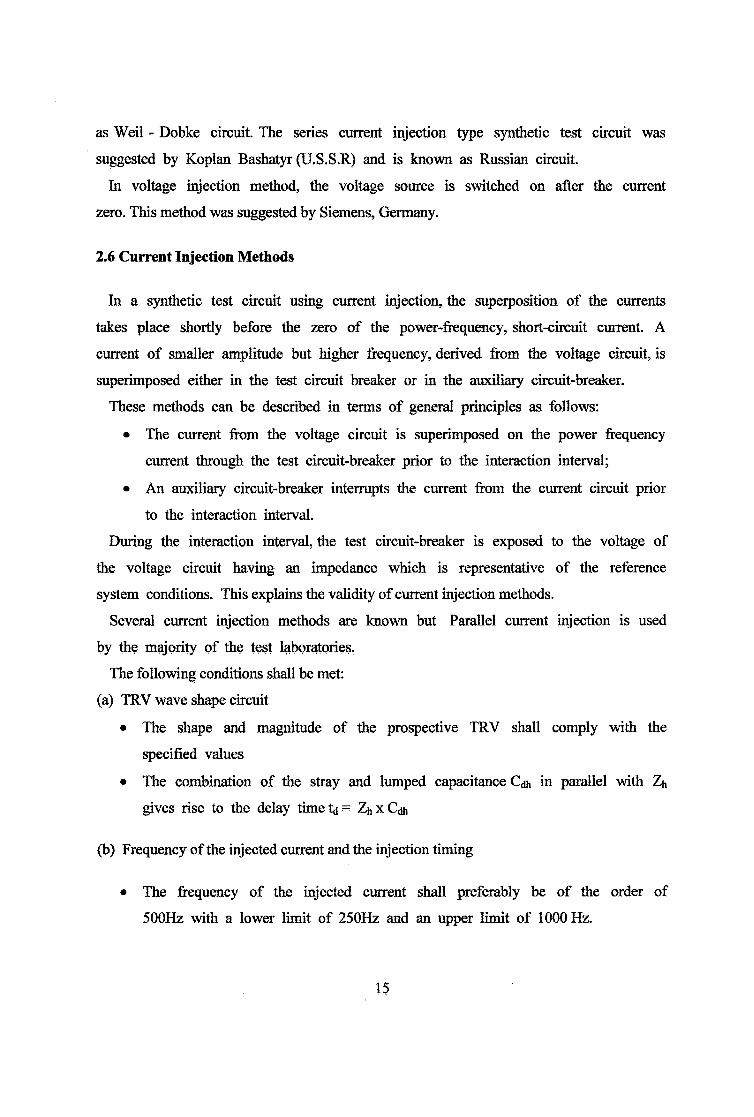
2.6 Current Injection Methods
In a synthetic test circuit using current injection, the superposition of the currents
takes place shortly before the zero of the power-frequency, short-circuit current. A
current of smaller amplitude but higher frequency, derived from the voltage circuit, is
superimposed either in the test circuit breaker or in the auxiliary circuit-breaker.
These methods can be described in terms of general principles as follows:
• The current from the voltage circuit is superimposed on the power frequency
current through the test circuit-breaker prior to the interaction interval;
• An auxiliary circuit-breaker interrupts the current from the current circuit prior
to the interaction interval.
During the interaction interval, the test circuit-breaker is exposed to the voltage of
the voltage circuit having an impedance which is representative of the reference
system conditions. This explains the validity of current injection methods.
Several current injection methods are known but Parallel current injection is used
by the majority of the test laboratories.
The following conditions shall be met:
(a) TRV wave shape circuit
• The shape and magnitude of the prospective TRV shall comply with the
specified values
• The combination of the stray and lumped capacitance Cdh in parallel with Zh
gives rise to the delay time ta = Zh x C*
(b) Frequency of the injected current and the injection timing
• The frequency of the injected current shall preferably be of the order of
500Hz with a lower limit of 250Hz and an upper limit of 1000 Hz.
15
• The initiation of the injected current shall be adjusted such that the time,
during which the test circuit-breaker is fed only by the injected current, is not
more than a quarter of the period of the injected current frequency with a
maximum of 500ps.
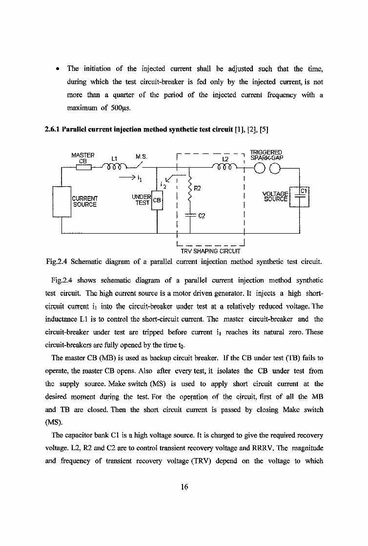
2.6.1 Parallel current Injection method synthetic test circuit [1], [2], [5]
I_________________ ITRV SHAPING CIRCUIT
Fig.2.4 Schematic diagram of a parallel current injection method synthetic test circuit.
Fig.2.4 shows schematic diagram of a parallel current injection method synthetic
test circuit. The high current source is a motor driven generator. It injects a high short-
circuit current u into the circuit-breaker under test at a relatively reduced voltage, The
inductance LI is to control the short-circuit current. The master circuit-breaker and the
circuit-breaker under test are tripped before current ii reaches its natural zero. These
circuit-breakers are frilly opened by the time t2-
The master CB (MB) is used as backup circuit breaker. If the CB under test (TB) fails to
operate, the master CB opens. Also after every test, it isolates the CB under test from
the supply source. Make switch (MS) is used to apply short circuit current at the
desired moment during the test. For the operation of the circuit, first of all the MB
and TB are closed. Then the short circuit current is passed by closing Make switch
(MS).
The capacitor bank Cl is a high voltage source. It is charged to give the required recovery
voltage. L2, R2 and C2 are to control transient recovery voltage and RRRV. The magnitude
and frequency of transient recovery voltage (TRV) depend on the voltage to which
16

TIME mUUseeunds
Fig.2.5 Relationship between primary current and injected current in a synthetic testparallel current injection scheme
the capacitor bank Cl is charged and the circuit parameters. The triggered spark gap
is fired slightly before the short circuit current ii reaches its natural zero. There is a
control circuit to fire the triggered spark gap at the desired moment. The closing and
opening of the circuit breakers at the desired moment is done by the Automatic
controller.
In Fig.2.5 and Fig.2.6, the relationship between the power frequency and the
injected current is shown.
The test is initiated by closing the making switch (MS), which initiates the flow of
the current ij, from the high current source through the isolating breaker and test
breaker(TB). As the cunent approaches its zero crossing the spark gap is triggered
and at time fr, the injected current i2 begins to flow. The current ii + i2 flow through
the test breaker until the time t2 is reached. This is the time when the main current ii
goes to zero and when the isolation breaker separates the two power sources.
At time ts the injected current is interrupted and the high voltage supplied by the
high voltage source provides the desired TRV which subsequently appears across the
terminals of the circuit-breaker that is being tested.
17

Fig.2.6 Expanded view of the parallel current injection near cunrent zero
Sequence of operation
• At time tq, the make switch M is closed and the normal power frequency
current ii flows in the circuit-breaker under test.
• At time ti, the spark gap S is fired and the current 12 flows in the test
breaker. The frequency of this current is determined by L2 and C2 so that
peak approximately coincides with zero of current ii.
• The current ii + i2 flow through the test breaker until the time t2 is reached.
This is the time when the main current ii goes to zero and when the isolation
breaker separates the two power sources.
• At time t2, when the current ii becomes zero it is interrupted by the auxiliary
breaker and the test breaker carries current i2 from the voltage circuit.
• When this current becomes zero at time t3, the transient recovery voltage
(TRV) appears across the circuit-breaker under test. The magnitude and the
frequency of this TRV depend on the voltage to which the capacitor Ci is
charged and the circuit parameters L2 and C2.
Breaking capacities up to ten or more times the short- circuit capacity of the
short-circuit generator can be achieved.
18
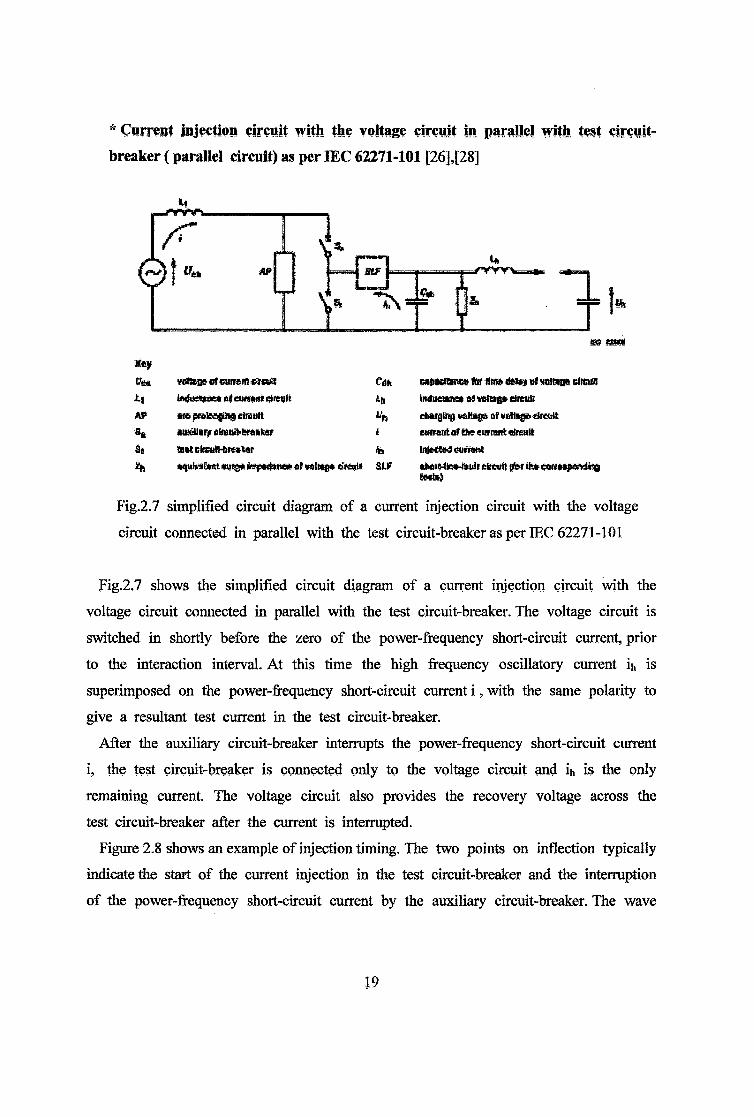
* Current injection circuit with the voltage circuit in parallel with test circuit-
breaker (parallel circuit) as per IEC 62271-101 [26],[28]
m megMay
Ms* vsitega «f evtreift cgwtt Cdh tar Urns dH»* ol wtiSas drew!
iftduettae* alaiMMt dfltuli ±(1 iRdueiane* -rtittg* chtiihAS* are preleagiiif elrcult charging waHaga of Mating* Ureutt
ri^ aieaiaqr efiBui!>Sre»tsar l current ar Sst eiifrant «jreult
St MtirlrHilMmAw Ih IhfecteS eurnsnt
•quh-juant auig* fcspar&ite* af valiag* tfreoit air efecsiit (ta tit* ea*Mi(Mrtdic*9Seals}
Fig.2.7 simplified circuit diagram of a current injection circuit with the voltage
circuit connected in parallel with the test circuit-breaker as per IEC 62271-101
Fig.2.7 shows the simplified circuit diagram of a current injection circuit with the
voltage circuit connected in parallel with the test circuit-breaker. The voltage circuit is
switched in shortly before the zero of the power-frequency short-circuit current, prior
to the interaction interval. At this time the high frequency oscillatory current ih is
superimposed on the power-frequency short-circuit current i, with the same polarity to
give a resultant test current in the test circuit-breaker.
After the auxiliary circuit-breaker interrupts the power-frequency short-circuit current
i, the test circuit-breaker is connected only to the voltage circuit and ih is the only
remaining current. The voltage circuit also provides the recovery voltage across the
test circuit-breaker after the current is interrupted.
Figure 2.8 shows an example of injection timing. The two points on inflection typically
indicate the start of the current injection in the test circuit-breaker and the interruption
of the power-frequency short-circuit current by the auxiliary circuit-breaker. The wave
19
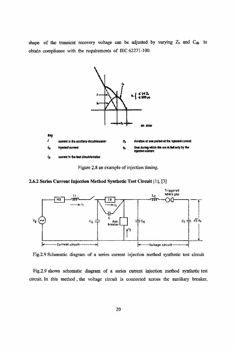
shape of the transient recovery voltage can be adjusted by varying Zh and Cdh to
obtain compliance with the requirements of IEC 62271-100.
£ty
s auirent In His snsaarf «tairtfrfcra!l»r Tit durstlM «fnna parted «f tl» litiseted onrant
4 % fine* HtfMg tte&h Ut it M oily hj ft*
k swrtfrt in 4i* diSutt-tewfer
iniatitedcwiwg
Figure 2.8 an example of injection timing.
2.6.2 Series Current Injection Method Synthetic Test Circuit [1], [3]
Triggered
Fig.2.9 shows schematic diagram of a series current injection method synthetic test
circuit. In this method, the voltage circuit is connected across the auxiliary breaker,
20

instead of the test breaker and the source capacitance. The voltage
to current circuit in series before main current zero.
The capacitor Cj is charged to the opposite polarity, so that inje
in the opposite direction to the power frequency (50Hz) current ii and thus subtracts
from it.
As the current and voltage circuits are series connected, it is difficult to select
circuit parameters to suit both the current and voltage circuits which would at the
same time give the required transient recovery voltage.
At time t2, when the currents ii and i2 are equal and opposite, the current in the
isolating breaker is interrupted and during the time from t2 to t3, the current flowing
through the test breaker is i3.
In Fig.2.10 and Fig.2.11, the relationship between the power frequency and the injected current is shown.
Fig.2.10 Relationship between primary current and injected current in a synthetic testseries current injection scheme
21
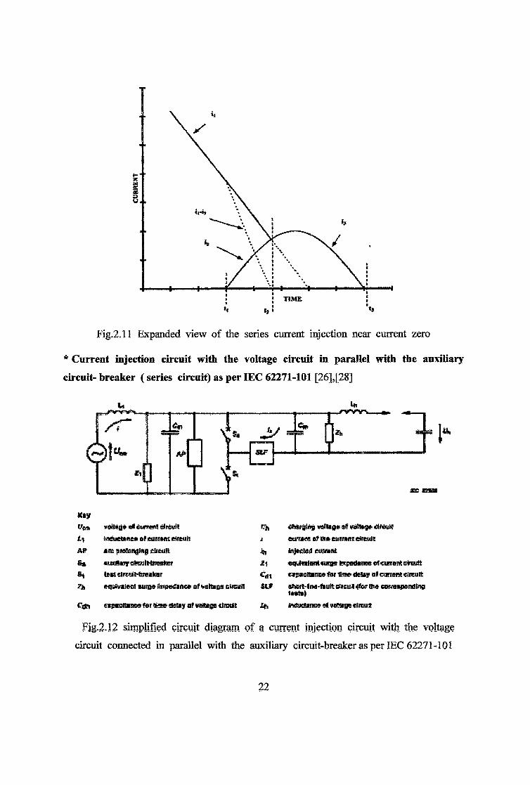
Fig.2.11 Expanded view of the series current injection near current zero
* Current injection circuit with the voltage circuit in parallel with the auxiliary
circuit- breaker ( series circuit) as per IEC 62271-101 [26],[28]
Vft*
AP
*1
<el Guntfiii sired!Muetenst euHMt drain
in pretending circuit auttOvy oteulHiMflfeer lest circuit* realtoreqtfvatenf miB» iinpatfince at vattzas cticuil
Con eapaottineeterSsedsbyiifwgligatlnHit
1% c&kralng votes* st votes* drM!j eaf»#e of B» cummh dreultij, injected currant£l ecMwIwnaum* tepedanee efcwrent olraiittC^t capacitance for time cteiay ol cunwft circuitSLf ihcrt-lna-fault oncu! <tw the currcepomting
taatallh Muoance el MdSaae clrau t
Fig.2,12 simplified circuit diagram of a current injection circuit with the voltage
circuit connected in parallel with the auxiliary circuit-breaker as per IEC 62271-101
22

Fig.2.12 shows the simplified circuit diagram of a current injection circuit with the
voltage circuit connected in parallel with the auxiliary circuit-breaker. After switching
in the voltage circuit, shortly before zero of the power-frequency, short-circuit current,
the high-frequency oscillatory current ih is superimposed, with opposing polarity, on the
power-frequency short-circuit current i, in the auxiliary circuit-breaker.
After the resulting current in the auxiliary circuit-breaker has ceased to flow, the
oscillatory current commutates into the test circuit-breaker and the current circuit. The
test circuit-breaker is now part of a circuit which comprises the series connected
current circuit and the voltage circuit. After the extinction of the resulting the
resulting current in the test circuit-breaker, the transient recovery voltage is supplied
both by the voltage circuit and the current circuit.
Fig.2.13 shows an example of injection timing. The single point of inflection
corresponds to the interruption of current in the auxiliary circuit-breaker. The wave
shape of the transient recovery voltage can be adjusted by varying Zh and Cdh as
well as Z i and Qj to obtain compliance with the requirements of IEC 62271-100.
Jityi currant £» me amilluy eireufi<fcifls»tair % time dining wWratlKi are fey the
tiMt% tejadad tast-uA dutaigaaedoM paired of tta tojitsid minesip eu«rtmiA ra» 1**1
Figure 2.13 an example of injection timing
2.7 Voltage Injection Methods as per IEC 62271-101 [26], [28]
In a synthetic test circuit using voltage injection, the current circuit provides the
entire short-circuit current for the test circuit-breaker and also, after current zero, the
first part of the transient recovery voltage.
By suitable choices of its voltage and natural frequency, the correct values of the
power factor, current and first part of the TRV can be obtained.
About the time of the first peak of the transient recovery voltage of the current
circuit, the voltage circuit is switched in by means of a voltage-dependent control
circuit in such a way that the specified transient recovery voltage is continued and so
that there will be no delay between the current stress and the voltage stress.
In these methods,
• The voltage from the voltage circuit is applied to the test circuit-breaker after
the interaction interval;
» A capacitor in parallel with the auxiliary circuit-breaker is used to apply the
recovery voltage to the test circuit-breaker;
• During the high current and interaction intervals, the test circuit-breaker is
exposed to the current circuit only.
Several voltage injection methods are known but only Series voltage injection
method is used by the test laboratories.
(1) Voltage injection circuit with the voltage circuit in parallel with the auxiliary
circuit-breaker (Series circuit)
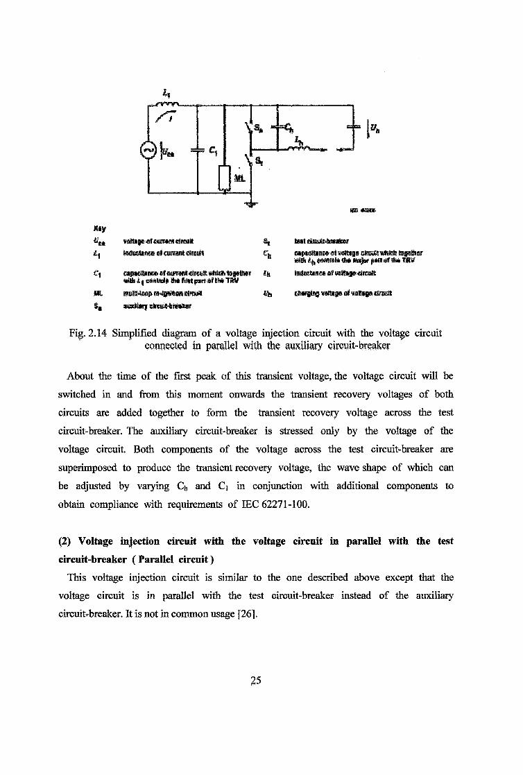
Fig.2.14 shows the simplified diagram of a voltage injection circuit with the voltage
circuit connected in parallel with the auxiliary circuit-breaker. The current circuit
supplies the entire short-circuit current stress.
A capacitor of suitable value is connected in parallel with the auxiliary circuit-
breaker. After the current zero of the power-frequency short-circuit current, this
capacitor transmits the entire transient recovery voltage of the current circuit to the
test circuit-breaker, passing the necessary energy for the post-arc current.
%
Kl/¥fiti»|je ofHirr#** circuit Muttee* af eureant timitt
C\ cipKttinro of cik-mw clreult utitoh iGjsthMtafEh11 eAAUdi ttMt lint pifl if B» TSV
ML multMaap r^saitioftfil'eujl$4 issfliij eireuJS-teSMif
SE tHteiRdbbMafcct
Ch uphRmik «1 vcttasa cfnaa wfifch falsifiertRitfi fcMflttti 0* ttaijpi pifl al lii« TRV
£h ln*KUnesof»iis*<*lieua
ife, &Dvb1a9 wtt*sa af yaltsge lireutt
Fig. 2.14 Simplified diagram of a voltage injection circuit with the voltage circuit connected in parallel with die auxiliary cirwit-breaker
About the time of the first peak of this transient voltage, the voltage circuit will be
switched in and from this moment onwards the transient recovery voltages of both
circuits are added together to form the transient recovery voltage across the test
circuit-breaker. The auxiliary circuit-breaker is stressed only by the voltage of the
voltage circuit. Both components of the voltage across the test circuit-breaker are
superimposed to produce the transient recovery voltage, the wave shape of which can
be adjusted by varying Ch and Ci in conjunction with additional components to
obtain compliance with requirements of IEC 62271-1GQ.
(2) Voltage injection circuit with the voltage circuit in parallel with the test
circuit-breaker (Parallel circuit)
This voltage injection circuit is similar to the one described above except that the
voltage circuit is in parallel with the test circuit-breaker instead of the auxiliary
circuit-breaker. It is not in common usage [26].
25

2.8 Comparison of Various Synthetic Test Circuits
In synthetic testing circuits, an AB (auxiliary breaker) is necessary to separate the
current source and the voltage source. The insertion of the AB in a synthetic test
circuit introduces an extra arc voltage in the test circuit and makes the arc-circuit
interaction of the IB different from the interaction in the direct test
circuit[15],[26],[28].
In synthetic test circuits, the ratio of the driving voltage of the current source with
respect to the arc voltages is low, because the driving voltage is a fraction of the
rated voltage and the arc voltages of TB and AB add up. As a result, the duration of
the first current loop and also the arc energy in the TB is reduced. The arc energy
reduction in the TB varies with the arc duration i.e. the arcing time of file TB[15].
For the synthetic test circuit, the total arc energy input in the TB is less than in
the direct test circuit, but just before the current zero the dl/dt and subsequently the
arc energy input in the TB is higher. It is demonstrated that the arc-circuit
interaction plays an important role for TB to clear the fault.
For SFg circuit-breakers with an arc voltage with significant extinguishing peak, the
voltage injection synthetic test circuit produces an overstress for the TB[15].
Presently two types of synthetic test circuits, based on the injection method of a
high voltage circuit are in use, the parallel current injection circuit and the series
voltage injection circuit[15]. For both the circuits, the insertion of AB gives the same
influence on the TB in the high current interval. However, in the interaction period
around current zero, the influence is different. The arc voltages of TB and AB shorten
the first current loop and extend the second current loop. The arc voltages of the AB
and TB have an influence such that the dl/dt before the first current zero is higher
than the dl/dt in the corresponding direct test circuit. A higher dl/dt means for the
TB in the series voltage injection synthetic test circuit, although the total arc
energy input is lower, the arc energy input per time unit just before current
zero is higher [15].
26

Arc voltage influence during the current zero periods:
For a small arc time constant, as in SFg, the arc voltage just before current zero is
important for the breakers. The arc voltage can influence the arc-circuit interaction
and this can affect the interrupting capability of the breaker.
From the calculations performed, it is concluded that, the voltage injection synthetic
test circuit puts more stress on the TB than the direct and current injection circuits
do during the current zero period. The AB in the voltage injection synthetic test
circuit causes the overstress on the TB during current zero period. The higher the
extinguishing peak in the AB, the more difficult it is for the TB to clear the
fault[15].
Depending on the interrupter design, there are several shapes of arc voltage
waveforms for a breaker when it clears a fault current, one shape is the arc voltage
with an extinguishing peak, another shape is the arc voltage with a less significant
extinguishing peak or an arc voltage without extinguishing peak.
Also Voltage injection method requires a very accurate timing for the voltage
injection. This timing becomes a critical parameter which in most cases is rather
difficult to control. Therefore this method is not very popular [1].
In series current injection method, as the current and voltage circuits are series
connected, it is rather difficult to select circuit parameters to suit both the current
and voltage circuits which would at the same time give required restriking voltage
transient This circuit arrangement is particularly suited for low frequency circuit[3].
More than forty years of synthetic testing experience shows that the current
injection method has better equivalence than the voltage injection method. To produce
four-parameter TRV, several TRV circuits have been developed but parallel current
injection method with a Weil-Dobke TRV control circuit is the most popular used
synthetic testing circuit in the high power laboratories as it is capable of providing
RRRV and recovery voltage as required by various standards. Weil-Dobke circuit has
a low capacity requirement on the main capacitor bank as compared to other TRV
control circuits and is easy to design the various components. However, special
attention should be paid on the insulation coordination of TRV
branches[14],[15],[17],[18],[19].
27