Embed Size (px)
Citation preview

Chapter 2: Implementing VLANs in Campus Networks
CCNP SWITCH: Implementing IP SwitchingCCNP SWITCH: Implementing IP Switching
© 2007 – 2010, Cisco Systems, Inc. All rights reserved. Cisco PublicSWITCH v6 Chapter 2
1

Chapter 2 Objectives Design and plan VLANs, trunks, and addressing to meet
business requirements, technical requirements, and constraintsconstraints. Configure VLANs and VLAN trunks in the campus network
to support business and technical requirements.pp q Configure VTP in the campus network to support business
and technical requirements. Describe private VLANs and configure private VLANs in the
campus network to support business and technical requirements.q Configure and verify an EtherChannel in a Layer 2 topology
that contains bridging loops.
Chapter 22© 2007 – 2010, Cisco Systems, Inc. All rights reserved. Cisco Public

Implementing VLANVLAN Technologies in a Campus NetworkNetwork
Chapter 23© 2007 – 2010, Cisco Systems, Inc. All rights reserved. Cisco Public

Virtual Local Area Network (VLAN)
A VLAN i l i l f d d i A VLAN is a logical group of end devices. Broadcasts are contained within VLANs. Modern design has 1 VLAN = 1 IP subnet Modern design has 1 VLAN = 1 IP subnet. Trunks connect switches so as to transport multiple VLANs. Layer 3 devices interconnect VLANs.
Chapter 24© 2007 – 2010, Cisco Systems, Inc. All rights reserved. Cisco Public
Layer 3 devices interconnect VLANs.

End-to-End VLANs
E h VLAN i di t ib t d hi ll th h t th t k Each VLAN is distributed geographically throughout the network. Users are grouped into each VLAN regardless of the physical location,
theoretically easing network management. As a user moves throughout a campus, the VLAN membership for that
user remains the same. Switches are configured for VTP server or client mode.
Chapter 25© 2007 – 2010, Cisco Systems, Inc. All rights reserved. Cisco Public
g

Local VLANs
C t l l VLAN ith h i l b d i i i d th th j b f ti f Create local VLANs with physical boundaries in mind rather than job functions of the users.
Local VLANs exist between the access and distribution layers. T ffi f l l VLAN i t d t th di t ib ti d l l Traffic from a local VLAN is routed at the distribution and core levels.
Switches are configured in VTP transparent mode. Spanning tree is used only to prevent inadvertent loops in the wiring closet.
Chapter 26© 2007 – 2010, Cisco Systems, Inc. All rights reserved. Cisco Public
One to three VLANs per access layer switch recommended.

VLANs in Enterprise Campus Design
VLAN d t th l h ld t d f th th th i VLANs used at the access layer should extend no further than their associated distribution switch.
Traffic is routed from the local VLAN as it is passed from the distribution l i hlayer into the core.
Blocks can contain one to three VLANs each. STP is limited to access and distribution switches.
Chapter 27© 2007 – 2010, Cisco Systems, Inc. All rights reserved. Cisco Public
DHCP is used to assign IP addresses to users.

Best Practices for VLAN Design One to three VLANs per access module and limit those VLANs to a couple of
access switches and the distribution switches. Avoid using VLAN 1 as the "blackhole" for all unused ports. Use a dedicated
VLAN separate from VLAN 1 to assign all the unused ports. Separate the voice VLANs, data VLANs, the management VLAN, the native
VLAN, blackhole VLANs, and the default VLAN (VLAN 1). Avoid VTP when using local VLANs; use manually allowed VLANs on trunks. For trunk ports, turn off Dynamic Trunking Protocol (DTP) and configure
trunking. Use IEEE 802.1Q rather than ISL because it has better support for Q S d i t d d t lQoS and is a standard protocol.
Manually configure access ports that are not specifically intended for a trunk link. P t ll d t t ffi f VLAN 1 l it t l t l t Prevent all data traffic from VLAN 1; only permit control protocols to run on VLAN 1 (DTP, VTP, STP BPDUs, PAgP, LACP, CDP, etc.).
Avoid using Telnet because of security risks; enable SSH support on management VLANs
Chapter 28© 2007 – 2010, Cisco Systems, Inc. All rights reserved. Cisco Public
management VLANs.

VLAN Support on Catalyst SwitchesCatalyst Switch Max VLANs VLAN ID Range
2940 4 1 - 10052940 4 1 1005
2950/2955 250 1 - 4094
2960 255 1 - 4094
2970/3550/3560/3750 1055 1 - 4094
2848G/2980G/4000/4500 4094 1 - 4094
6500 4094 1 - 4094
Chapter 29© 2007 – 2010, Cisco Systems, Inc. All rights reserved. Cisco Public

VLAN Ranges on Catalyst SwitchesVLAN Range Range Usage Popagated via VTP?
0, 4095 Reserved For system use only. You cannot see n/ay yor use these.
1 Normal Cisco default. You can use this VLAN, but you cannot delete it.
Yes
2 – 1001 Normal For Ethernet VLANs. You can create, use, and delete these.
Yes
1002 – 1005 Normal Cisco defaults for FDDI and Token YesRing. You cannot delete these.
1006 – 1024 Reserved For system use only. You cannot see or use these.
n/a
1025 - 4094 Reserved For Ethernet VLANs only. VTP v 3 only. Not supported in VTP v1 or v2. Requires VTP transparent mode for
Chapter 210© 2007 – 2010, Cisco Systems, Inc. All rights reserved. Cisco Public
pconfiguration.

Configuration: Create a VLAN To create a new VLAN in global configuration mode.Switch(config)# vlan vlan-id
i 2 1001 1025 4094 vlan-id is 2-1001 or 1025-4094
Chapter 211© 2007 – 2010, Cisco Systems, Inc. All rights reserved. Cisco Public

Configuration: Name a VLAN To name a VLAN in VLAN configuration mode.Switch(config-vlan)# name vlan-name
i d i t f th VLAN vlan-name is a descriptor for the VLAN. Naming a VLAN is optional.
Chapter 212© 2007 – 2010, Cisco Systems, Inc. All rights reserved. Cisco Public
Example: Creating and Naming a VLAN Enter global configuration mode:
Switch# configure terminalC t VLAN ith ti l ID b Create a new VLAN with a particular ID number:Switch(config)# vlan vlan-id
(Optional ) Name the VLAN:(Optional.) Name the VLAN:Switch(config-vlan)# name vlan-name
Switch# configure terminalSwitch# configure terminalSwitch(config)# vlan 5Switch(config-vlan)# name EngineeringSwitch(config-vlan)# exit
Chapter 213© 2007 – 2010, Cisco Systems, Inc. All rights reserved. Cisco Public

Configuration: Disable Trunk Negotiation on a PortPort To disable trunk negotiation on a switch port.Switch(config-if)# switchport mode access( g ) p
This command is optional but is recommended for security purposes. An access port does not need to negotiate trunk f tiformation.
Chapter 214© 2007 – 2010, Cisco Systems, Inc. All rights reserved. Cisco Public
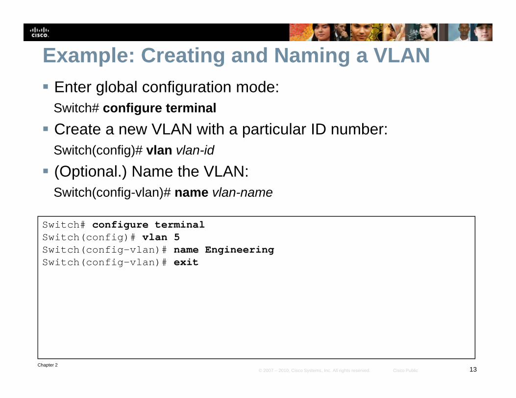
Configuration: Macro for Access Port To configure an optional macro for switch access ports.Switch(config-if)# switchport host
Thi d i i L 2 f h This command optimizes a Layer 2 port for a host connection. This macro sets the port mode to access enablesThis macro sets the port mode to access, enables
spanning-tree portfast, and disables EtherChannel.
Chapter 215© 2007 – 2010, Cisco Systems, Inc. All rights reserved. Cisco Public

Configuration: Assign Port to VLAN To assign a port to a VLAN in interface configuration mode.Switch(config-if)# switchport access vlan vlan-id
i i l t d VLAN vlan-id is a previously created VLAN.
Chapter 216© 2007 – 2010, Cisco Systems, Inc. All rights reserved. Cisco Public

Example: Assigning a Port to a VLAN Enter interface configuration
mode:Switch(config)# interface
Assign port to VLAN:Switch(config-if)# switchport access vlan vlan-idg
interface-id
Configure a description for the device(s) connected to the port:
Enable the interface:Switch(config-if)# no shutdown
Return to Privileged EXEC modeSwitch(config-if)# description string
Configure access port macro:
Return to Privileged EXEC modeSwitch(config-if)# end
Switch(config-if)# switchport host
Switch(config)# interface FastEthernet 5/6Switch(config-if)# description PC AS i h( fi if)# it h t h tSwitch(config-if)# switchport hostswitchport mode will be set to access spanning-tree portfast will be enabled channel group will be disabled Switch(config-if)# switchport access vlan 200Switch(config-if)# no shutdown
Chapter 217© 2007 – 2010, Cisco Systems, Inc. All rights reserved. Cisco Public
Switch(config if)# no shutdownSwitch(config-if)# end

Verification: VLAN Configuration The show vlan command and its derivatives are the most
useful commands for displaying information related to VLANs The following two forms have the same outputVLANs. The following two forms have the same output.
Switch# show vlan id 3VLAN Name Status Ports
---- -------------------------------- --------- -------------------------------
3 VLAN0003 active Fa0/1
VLAN T SAID MTU P t Ri N B id N St B d M d T 1 T 2VLAN Type SAID MTU Parent RingNo BridgeNo Stp BrdgMode Trans1 Trans2
---- ----- ---------- ----- ------ ------ -------- ---- -------- ------ ------
3 enet 100003 1500 - - - - - 0 0
Switch# show vlan name VLAN0003VLAN Name Status Ports---- -------------------------------- --------- ---------------------3 VLAN0003 active Fa0/1
Chapter 218© 2007 – 2010, Cisco Systems, Inc. All rights reserved. Cisco Public
VLAN Type SAID MTU Parent RingNo BridgeNo Stp BrdgMode Trans1 Trans2---- ----- ---------- ----- ------ ------ -------- ---- -------- ------ ------3 enet 100003 1500 - - - - - 0 0

Verification: Interface Configuration The show running-config command has an interface keyword option to allow for interface-specific outputoutput.
Switch# show running-config interface FastEthernet 5/6Building configuration...!Current configuration :33 bytesinterface FastEthernet 5/6switchport access vlan 200pswitchport mode accessswitchport hostend
Chapter 219© 2007 – 2010, Cisco Systems, Inc. All rights reserved. Cisco Public

Verification: Switch Port Configuration One of the most useful commands for showing VLAN
configuration information specific to a switch port is the show interfaces interface id switchportshow interfaces interface_id switchportcommand.
Switch# show interfaces f0/18 switchportSwitch# show interfaces f0/18 switchportName: Fa0/18Switchport: EnabledAdministrative Mode: static accessOperational Mode: downd i i i ki l i d 1Administrative Trunking Encapsulation: dot1q
Negotiation of Trunking: OffAccess Mode VLAN: 20 (VLAN0020)Trunking Native Mode VLAN: 1 (default)Administrative Native VLAN tagging: enabledgg gVoice VLAN: 150 (VLAN0150)<output omitted>Operational private-vlan: noneTrunking VLANs Enabled: ALLPruning VLANs Enabled: 2 1001
Chapter 220© 2007 – 2010, Cisco Systems, Inc. All rights reserved. Cisco Public
Pruning VLANs Enabled: 2-1001Capture Mode DisabledCapture VLANs Allowed: ALL

Verification: MAC Address Information You can view MAC address information specific to an
interface and an associated VLAN.
Switch# show mac-address-table interface GigabitEthernet 0/1 vlan 1
Mac Address Table------------------------------------------Vlan Mac Address Type Ports---- ----------- ---- -----1 0008.2199.2bc1 DYNAMIC Gi0/1
Total Mac Addresses for this criterion: 1
Chapter 221© 2007 – 2010, Cisco Systems, Inc. All rights reserved. Cisco Public
ImplementingImplementing Trunking in a Campus Network
Chapter 222© 2007 – 2010, Cisco Systems, Inc. All rights reserved. Cisco Public

VLAN Trunking Trunks carry the traffic for multiple VLANs across a single
physical link (multiplexing). Trunking is used to extend Layer 2 operations across an entire networkoperations across an entire network. The host on the left in VLAN 2 can communicate with the host on
the right in VLAN 2 via the trunk link; over the same trunk link, the hosts on VLAN 1 can communicate simultaneously.
Chapter 223© 2007 – 2010, Cisco Systems, Inc. All rights reserved. Cisco Public

VLAN Trunking with Inter-Switch Link (ISL)
ISL is Cisco proprietary trunking protocol ISL is Cisco-proprietary trunking protocol. ISL is nearly obsolete. ISL encapsulates Ethernet frames adding 30 bytes ofISL encapsulates Ethernet frames, adding 30 bytes of
overhead. ISL is supported on non-access-layer Cisco switches.
Chapter 224© 2007 – 2010, Cisco Systems, Inc. All rights reserved. Cisco Public

VLAN Trunking with IEEE 802.1Q
802.1Q is a widely supported industry-standard protocol. IEEE 802.1Q has smaller frame overhead than ISL. 802.1Q
overhead is 4 bytes. 802.1Q has the 802.1p field for QoS support.
Chapter 225© 2007 – 2010, Cisco Systems, Inc. All rights reserved. Cisco Public

Native VLAN with IEEE 802.1Q
The 802 1Q standard specifies how the switch should handle untagged frames The 802.1Q standard specifies how the switch should handle untagged frames sent or received on an 802.1Q trunk port.
An 802.1Q trunk port is assigned a default PVID, which is associated with all untagged traffic on the port. All traffic with a null VLAN ID is assumed to belong gg p gto the port default PVID. A packet with a VLAN ID equal to the outgoing port default PVID is sent untagged. All other traffic is sent with a VLAN tag.
Proactively configuring both ends of an 802.1Q trunk link with a native VLAN
Chapter 226© 2007 – 2010, Cisco Systems, Inc. All rights reserved. Cisco Public
distinct from all other VLANs is recommended.

Dynamic Trunking Protocol (DTP)
Access - Puts the interface into permanent non-trunking mode and negotiates to convert the link into a non-trunk link. The interface becomes a non-trunk interface even if the neighboring interface does not agree to the change.
Trunk - Puts the interface into permanent trunking mode and negotiates to convert the link into a trunk link. The interface becomes a trunk interface even if the neighboring interface does not agree to the change.
Nonegotiate - Puts the interface into permanent trunking mode but prevents the interface from generating DTP frames. You must configure the neighboring interface manually as a trunk interface to establish a trunk link. Use this mode when connecting to a device that does not support DTP.
Dynamic desirable - Makes the interface actively attempt to convert the link to a trunk link. The interface becomes a trunk interface if the neighboring interface is set to trunk, desirable, or auto mode.
Dynamic auto - Makes the interface willing to convert the link to a trunk link. The interface becomes a trunk interface if
Chapter 227© 2007 – 2010, Cisco Systems, Inc. All rights reserved. Cisco Public
the neighboring interface is set to trunk or desirable mode. This is the default mode for all Ethernet interfaces in Cisco IOS.

Design with VLAN Trunks
Trunks interconnect access layer switches.
Trunks connect access layer switches to distribution layer switches.
Layer 3 links interconnect core and distribution layer switches.
Access layer switches are configured in a spanning-tree, loop-free, V-shaped topology. If one distribution link fails, HSRP or VRRP provide an alternative default gateway.
Chapter 228© 2007 – 2010, Cisco Systems, Inc. All rights reserved. Cisco Public
Recommended: turn off DTP and manually prune VLANs on trunks.

Configuring an Interface for Trunking Select the encapsulation type:Switch(config-if)# switchport trunk encapsulation {isl | dot1q | negotiate}
Configure the interface as a Layer 2 trunk:Switch(config-if)# switchport mode {dynamic {auto | desirable} | trunk}
S if th ti VLAN Specify the native VLAN:Switch(config-if)# switchport trunk native vlan vlan-id
Configure the allowable VLANs for this trunk:Switch(config-if)# switchport trunk allowed vlan {add | except | all | remove} vlan-id[,vlan-id[,vlan-id[,...]]]
Switch(config)# interface FastEthernet 5/8 S it h( fi if)# it h t t k l ti d t1Switch(config-if)# switchport trunk encapsulation dot1q Switch(config-if)# switchport mode trunk Switch(config-if)# switchport nonegotiate optionalSwitch(config-if)# switchport trunk allowed vlan 1-100 Switch(config-if)# no shutdown
Chapter 229© 2007 – 2010, Cisco Systems, Inc. All rights reserved. Cisco Public
gSwitch(config-if)# end

Verifying Trunk ConfigurationSwitch# show running-config interface f5/8Building configuration...Current configuration:!interface FastEthernet5/8switchport mode dynamic desirableswitchport trunk encapsulation dot1qend
Switch# show interfaces f5/8 switchportN F 5/8Name: Fa5/8Switchport: EnabledAdministrative Mode: dynamic desirableOperational Mode: trunkAdministrative Trunking Encapsulation: negotiateOperational Trunking Encapsulation: dot1qOperational Trunking Encapsulation: dot1qNegotiation of Trunking: EnabledAccess Mode VLAN: 1 (default)Trunking Native Mode VLAN: 1 (default)Trunking VLANs Enabled: ALLPruning VLANs Enabled: 2-1001
Switch# show interfaces f5/8 trunkPort Mode Encapsulation Status Native vlanFa5/8 desirable n-802.1q trunking 1
Port Vlans allowed on trunk
Chapter 230© 2007 – 2010, Cisco Systems, Inc. All rights reserved. Cisco Public
Port Vlans allowed on trunkFa5/8 1-1005

Troubleshooting Trunk Links Ensure that the Layer 2 interface mode configured on both
ends of the link is valid. The trunk mode should be trunk or desirable for at least one side of the trunkdesirable for at least one side of the trunk. Ensure that the trunk encapsulation type configured on both
ends of the link is valid and compatible.p On IEEE 802.1Q trunks, make sure the native VLAN is the
same on both ends of the trunk. When using DTP, ensure that both ends of the link are in
the same VTP domain.
Chapter 231© 2007 – 2010, Cisco Systems, Inc. All rights reserved. Cisco Public

VLAN T kiVLAN Trunking Protocol
Chapter 232© 2007 – 2010, Cisco Systems, Inc. All rights reserved. Cisco Public

VLAN Trunking Protocol (VTP)
VTP is a Cisco-proprietary protocol that automates the propagation of VLAN information between switches via trunk links. This minimizes misconfigurations and configuration inconsistencies.
VTP does not configure switch ports for VLAN membership. Three types of VTP messages are sent via Layer 2 multicast on VLAN 1. VTP domains define sets of interconnected switches sharing the same
Chapter 233© 2007 – 2010, Cisco Systems, Inc. All rights reserved. Cisco Public
VTP domains define sets of interconnected switches sharing the same VTP configuration.

VTP ModesMode DescriptionClient • Cannot create, change, or delete VLANs on command-line interface
(CLI).• Forwards advertisements to other switches.• Synchronizes VLAN configuration with latest information received from
other switches in the management domain.• Does not save VLAN configuration in nonvolatile RAM (NVRAM).
Server • Can create, modify, and delete VLANs.• Sends and forwards advertisements to other switches.• Synchronizes VLAN configuration with latest information received fromSynchronizes VLAN configuration with latest information received from
other switches in the management domain.• Saves VLAN configuration in NVRAM.
Transparent • Can create, modify, and delete VLANs only on the local switch.F d VTP d ti t i d f th it h i th• Forwards VTP advertisements received from other switches in the same management domain.
• Does not synchronize its VLAN configuration with information received from other switches in the management domain.S VLAN fi ti i NVRAM
Chapter 234© 2007 – 2010, Cisco Systems, Inc. All rights reserved. Cisco Public
• Saves VLAN configuration in NVRAM.

VTP Operation
Chapter 235© 2007 – 2010, Cisco Systems, Inc. All rights reserved. Cisco Public

VTP Pruning
VTP pruning prevents flooded traffic from propagating to switches that do not have members in specific VLANs.
VTP pruning uses VLAN advertisements to determine when a trunk connection VTP pruning uses VLAN advertisements to determine when a trunk connection is flooding traffic needlessly. Switches 1 and 4 in the figure support ports statically configured in the Red VLAN.
The broadcast traffic from Station A is not forwarded to Switches 3 5 and 6
Chapter 236© 2007 – 2010, Cisco Systems, Inc. All rights reserved. Cisco Public
The broadcast traffic from Station A is not forwarded to Switches 3, 5, and 6 because traffic for the Red VLAN has been pruned on the links indicated on Switches 2 and 4.

VTP Versions Three VTP versions: V1, V2, V3. Versions are not interoperable (e.g., V2 supports token ring VLANs but
V1 does not)V1 does not). Unrecognized Type-Length-Value (TLV) configuration changes are
propagated by V2 servers and clients and these unrecognized TLVs can be stored in NVRAMbe stored in NVRAM.
V1 transparent switches inspect VTP messages for the domain name and version and forward a message only if the version and domain name match V2 transparent switches forward VTP messages inname match. V2 transparent switches forward VTP messages in transparent mode without checking versions.
V2 performs VLAN consistency checks (VLAN names and values) only when you enter new information through the CLI or via SNMP V2 doeswhen you enter new information through the CLI or via SNMP. V2 does not perform checks when new information is obtained from a VTP message or when information is read from NVRAM. If the MD5 hash on a received VTP message is correct, V2 accepts the VTP message
Chapter 237© 2007 – 2010, Cisco Systems, Inc. All rights reserved. Cisco Public
a received VTP message is correct, V2 accepts the VTP message information.

VTP Message Types Summary Advertisements Subset Advertisements Advertisement Requests
Chapter 238© 2007 – 2010, Cisco Systems, Inc. All rights reserved. Cisco Public

VTP Summary Advertisements
By default, Catalyst switches issue summary advertisements in 5-minute increments. Summary advertisements inform adjacent switches of the current VTP domain name and the configuration revision number.
When the switch receives a summary advertisement packet, the switch compares the VTP domain name to its own VTP domain name. If the name is different, the switch ignores the packet. If the name is the same, the switch then compares the configuration revision to its own revision. If its own configuration revision is higher or equal, the packet is i d If it i l d ti t t i t
Chapter 239© 2007 – 2010, Cisco Systems, Inc. All rights reserved. Cisco Public
ignored. If it is lower, an advertisement request is sent.

VTP Subset Advertisements
When you add, delete, or change a VLAN, the VTP server where the changes are made increments the configuration revision and issues achanges are made increments the configuration revision and issues a summary advertisement. One or several subset advertisements follow the summary advertisement.
A subset advertisement contains a list of VLAN information If there are A subset advertisement contains a list of VLAN information. If there are several VLANs, more than one subset advertisement can be required to advertise all the VLANs.
Chapter 240© 2007 – 2010, Cisco Systems, Inc. All rights reserved. Cisco Public

VTP Subset Advertisements
When you add, delete, or change a VLAN, the VTP server where the changes are made increments the configuration revision and issues a summary advertisement. One or several subset advertisements follow ythe summary advertisement.
A subset advertisement contains a list of VLAN information. If there are several VLANs, more than one subset advertisement can be required to
Chapter 241© 2007 – 2010, Cisco Systems, Inc. All rights reserved. Cisco Public
, qadvertise all the VLANs.
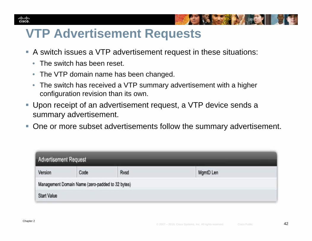
VTP Advertisement Requests A switch issues a VTP advertisement request in these situations:
• The switch has been reset.• The VTP domain name has been changed• The VTP domain name has been changed.• The switch has received a VTP summary advertisement with a higher
configuration revision than its own. Upon receipt of an advertisement request a VTP device sends a Upon receipt of an advertisement request, a VTP device sends a
summary advertisement. One or more subset advertisements follow the summary advertisement.
Chapter 242© 2007 – 2010, Cisco Systems, Inc. All rights reserved. Cisco Public

VTP Authentication VTP domains can be secured by using the VTP password
feature. It is important to make sure that all the switches in the VTP domain have the same password and domainthe VTP domain have the same password and domain name; otherwise, a switch will not become a member of the VTP domain. Cisco switches use MD5 to encode passwords in 16-byte words. These passwords propagate inside VTP summary advertisements. In VTP, passwords are case-sensitive and can be 8 to 64 characters in length. a e case se s e a d ca be 8 o 6 c a ac e s e gThe use of VTP authentication is a recommended practice. By default, a Catalyst switch does not have a VTP
d Th it h d t t ti ll t thpassword. The switch does not automatically set the password parameter, unlike other parameters that are set automatically when a VTP advertisement is received.
Chapter 243© 2007 – 2010, Cisco Systems, Inc. All rights reserved. Cisco Public
y

Configuring VTP Step 1. Enter global configuration mode: Switch# configure terminal
St 2 C fi th VTP d Step 2. Configure the VTP mode as server: Switch(config)# vtp mode server
Step 3. Configure the domain name: p gSwitch(config)# vtp domain domain_name
Step 4. (Optional.) Enable VTP version 2: i h( fi )# i 2Switch(config)# vtp version 2
Step 5. (Optional.) Specify a VTP password: Switch(config)# vtp password password string g p p p _ g
Step 6. (Optional.) Enable VTP pruning in the management domain: S it h( fi )# tp pr ning
Chapter 244© 2007 – 2010, Cisco Systems, Inc. All rights reserved. Cisco Public
Switch(config)# vtp pruning

VTP Configuration Example This example creates a VTP server with domain name Modular_Form, password genus, and pruning enabled.
Switch# configure terminalSwitch# configure terminalSwitch(config)# vtp mode serverSetting device to VTP SERVER mode.Switch(config)# vtp domain Modular_FormSwitch(config)# vtp password genusSwitch(config)# vtp password genusSwitch(config)# vtp pruning Switch(config)# end
Chapter 245© 2007 – 2010, Cisco Systems, Inc. All rights reserved. Cisco Public

Verifying VTP Configuration (1) The most useful command for verifying VTP configuration is
the show vtp status command. The output displayed includes the VTP version the VTP configuration revisionincludes the VTP version, the VTP configuration revision number, the number of VLANs supported locally, the VTP operating mode, the VTP domain name, and the VTP pruning mode.
Switch# show vtp statusSwitch# show vtp status VTP Version : 2 Configuration Revision : 247 Maximum VLANs supported locally : 1005 Number of existing VLANs : 33 VTP O ti M d SVTP Operating Mode : Server VTP Domain Name : Modular_Form VTP Pruning Mode : Enabled VTP V2 Mode : Disabled VTP Traps Generation : Disabled
Chapter 246© 2007 – 2010, Cisco Systems, Inc. All rights reserved. Cisco Public
MD5 digest : 0x45 0x52 0xB6 0xFD 0x63 0xC8 0x49 0x80 Configuration last modified by 0.0.0.0 at 8-12-99 15:04:4

Verifying VTP Configuration (2) Use the show vtp counters command to display
statistics about VTP operation. If there are any problems regarding the VTP operation this command helps look forregarding the VTP operation, this command helps look for VTP message type updates.
S itch# show vtp countersSwitch# show vtp countersVTP statistics:Summary advertisements received : 7Subset advertisements received : 5Request advertisements received : 0Summary advertisements transmitted : 997Summary advertisements transmitted : 997Subset advertisements transmitted : 13Request advertisements transmitted : 3Number of config revision errors : 0Number of config digest errors : 0Number of V1 summary errors : 0
VTP pruning statistics:
Trunk Join Transmitted Join Received Summary advts received from non-pruning-capable device
Chapter 247© 2007 – 2010, Cisco Systems, Inc. All rights reserved. Cisco Public
------ ---------------- ------------- -----------------Fa5/8 43071 42766 5

VTP Troubleshooting Check that switches are interconnected by active trunk
links.Ch k th t th t ki t l t h it d Check that the trunking protocol matches on opposite ends of a trunk link. Check VTP domain name (case-sensitive) and passwordCheck VTP domain name (case sensitive) and password. Check the VTP mode of the switches. Check the VTP versions of the switches.
Chapter 248© 2007 – 2010, Cisco Systems, Inc. All rights reserved. Cisco Public

Private VLANs
Chapter 249© 2007 – 2010, Cisco Systems, Inc. All rights reserved. Cisco Public
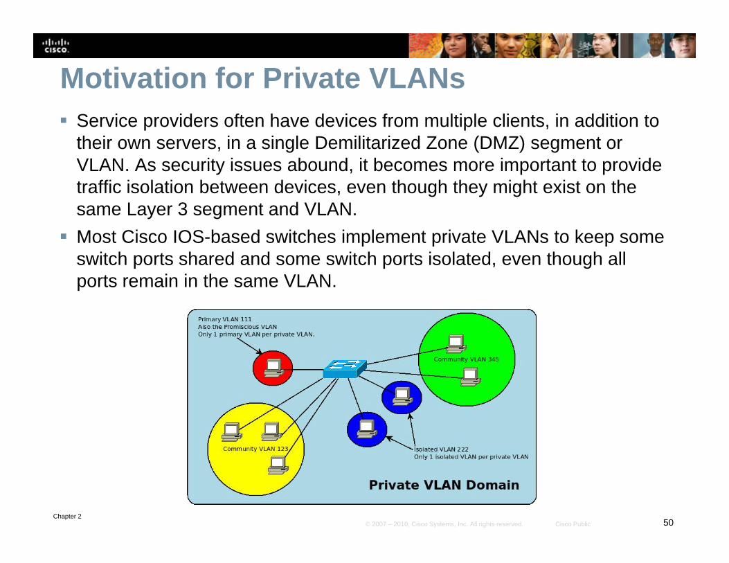
Motivation for Private VLANs Service providers often have devices from multiple clients, in addition to
their own servers, in a single Demilitarized Zone (DMZ) segment or VLAN. As security issues abound, it becomes more important to provide traffic isolation between devices, even though they might exist on the same Layer 3 segment and VLAN.
Most Cisco IOS-based switches implement private VLANs to keep some p p pswitch ports shared and some switch ports isolated, even though all ports remain in the same VLAN.
Chapter 250© 2007 – 2010, Cisco Systems, Inc. All rights reserved. Cisco Public

pVLAN Port Types Isolated Promiscuous Community
Chapter 251© 2007 – 2010, Cisco Systems, Inc. All rights reserved. Cisco Public
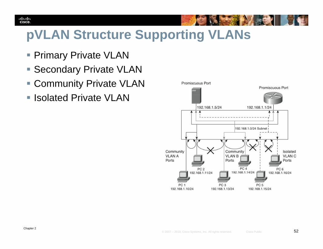
pVLAN Structure Supporting VLANs Primary Private VLAN Secondary Private VLAN Community Private VLAN Isolated Private VLAN
Chapter 252© 2007 – 2010, Cisco Systems, Inc. All rights reserved. Cisco Public

Configuring pVLANs - Steps Step 1. Set VTP mode to transparent. Step 2. Create the secondary pVLANs.
St 3 C t th i VLAN Step 3. Create the primary pVLAN. Step 4. Associate the secondary pVLAN with the primary pVLAN.
• Only one isolated pVLAN can be mapped to a primary pVLAN, but more O y o e so ated p ca be apped to a p a y p , but o ethan one community pVLAN can be mapped to a primary pVLAN.
Step 5. Configure an interface as an isolated or community port. Step 6 Associate the isolated port or community port with the Step 6. Associate the isolated port or community port with the
primary-secondary pVLAN pair. Step 7. Configure an interface as a promiscuous port. Step 8. Map the promiscuous port to the primary-secondary
pVLAN pair.
Chapter 253© 2007 – 2010, Cisco Systems, Inc. All rights reserved. Cisco Public

Configuring pVLANs - CommandsSwitch(config)# vlan pvlan-id
Switch(config-vlan)# private-vlan {community | isolated | primary}
Switch(config-vlan)# exit
Switch(config)# vlan primary-vlan-id
Switch(config-vlan)# private-vlan association {secondary-vlan-list | add secondary-vlan-list | remove secondary-vlan-list}
Switch(config-vlan)# interface vlan primary-vlan-idSwitch(config vlan)# interface vlan primary vlan id
Switch(config-if)# private-vlan mapping {secondary-vlan-list | add secondary-vlan-list | remove secondary-vlan-list}
Switch(config-if)# interface type slot/port
Switch(config-if)# switchport
Switch(config-if)# switchport mode private-vlan {host | promiscuous}
Switch(config-if)# switchport private-vlan host-association primary-vlan-id secondary vlan idid secondary-vlan-id
Switch(config-if)# switchport private-vlan mapping primary-vlan-id{secondary-vlan-list | add secondary-vlan-list | remove secondary-vlan-list}
Chapter 254© 2007 – 2010, Cisco Systems, Inc. All rights reserved. Cisco Public

Verifying pVLAN Configuration The two most useful commands for this purpose are show interface switchport and show vlan private-vlanvlan.
Switch# show vlan private-vlanPrimary Secondary Type Interfaces------- --------- -------------- -----------------100 200 community100 300 isolated
Switch# show interfaces FastEthernet 5/2 switchportName: Fa5/2Switchport: EnabledAdministrative Mode: private-vlan hostOperational Mode: downAdministrative Trunking Encapsulation: negotiateNegotiation of Trunking: OnAccess Mode VLAN: 1 (default)Access Mode VLAN: 1 (default)Trunking Native Mode VLAN: 1 (default)Administrative private-vlan host-association: 100 (VLAN0200) 300 (VLAN0300)Administrative private-vlan mapping: noneOperational private-vlan: noneTrunking VLANs Enabled: ALL
Chapter 255© 2007 – 2010, Cisco Systems, Inc. All rights reserved. Cisco Public
gPruning VLANs Enabled: 2-1001Capture Mode Disabled

pVLAN Scenario 1: Single Switch
A corporate DMZ contains two DNS servers, one web server and one SMTP server. All servers and their connecting router are in the same subnet.
DNS servers are redundant copies, so they need to communicate with each th t d t th i t i d t th I t t I dditi t th t th lother to update their entries and to the Internet. In addition to that, they also
need to communicate with the Internet. The Web Server and the SMTP server need to communicate with the Internet,
but for security purposes the SMTP server should not be reachable from the
Chapter 256© 2007 – 2010, Cisco Systems, Inc. All rights reserved. Cisco Public
but for security purposes, the SMTP server should not be reachable from the Web or the DNS servers. The web server needs to be accessible from the Internet but not from the SMTP server.

pVLAN Configuration for Scenario 1Switch(config)# vtp transparentSwitch(config)# vlan 201Switch(config-vlan)# private-vlan isolatedSwitch(config)# vlan 202S tc (co g)# aSwitch(config-vlan)# private-vlan communitySwitch(config-vlan)# vlan 100Switch(config-vlan)# private-vlan primarySwitch(config-vlan)# private-vlan association 201,202( g )# p ,Switch(config-vlan)# interface fastethernet 0/24Switch(config-if)# switchport mode private-vlan promiscuousSwitch(config-if)# switchport private-vlan mapping 100 201,202Switch(config-if)# interface range fastethernet 0/1 - 2( g )# g /Switch(config-if)# switchport mode private-vlan hostSwitch(config-if)# switchport private-vlan host-association 100 202Switch(config-if)# interface range fastethernet 0/3 - 4Switch(config-if)# switchport mode private-vlan host( g ) p pSwitch(config-if)# switchport private-vlan host-association 100 201
Chapter 257© 2007 – 2010, Cisco Systems, Inc. All rights reserved. Cisco Public

pVLAN Scenario 2: Multiple Switches
A trunk port carries the primary VLAN and secondary VLANs to a neighboring switchA trunk port carries the primary VLAN and secondary VLANs to a neighboring switch just like any other VLAN.
A feature of pVLANs across multiple switches is that traffic from an isolated port in one switch does not reach an isolated port on another switch.
Configure pVLANs on all switches on the path, which includes devices that have no pVLAN ports to maintain the security of your pVLAN configuration, and avoid using other VLANs configured as pVLANs. A h i th fi th it h SWA d SWB h th VLAN t
Chapter 258© 2007 – 2010, Cisco Systems, Inc. All rights reserved. Cisco Public
As shown in the figure, the switches SWA and SWB have the same pVLANs on two different switches and are connected through the trunk link.

pVLAN Configuration for Scenario 2 To configure a Layer 2 interface as a Private VLAN trunk port, use the interface
command:Switch(config-if)# switchport private-vlan association trunk primary_vlan_ID secondary_vlan_ID
If the port is set to promiscuous, use the mapping command:Switch(config-if)# switchport private-vlan mapping primary_vlan_ID secondary vlan listsecondary_vlan_list
Once the trunk is configured, allow VLANs with the commandSwitch(config-if)# switchport private-vlan trunk allowed vlan vlan listvlan_list
Configure the native VLAN with following commandSwitch(config-if)# switchport private-vlan trunk native vlan vlan_id
Switch(config)# interface fastethernet 5/2Switch(config-if)# switchport mode private-vlan trunk secondarySwitch(config-if)# switchport private-vlan trunk native vlan 10Switch(config-if)# switchport private-vlan trunk allowed vlan 10, 3,301-
Chapter 259© 2007 – 2010, Cisco Systems, Inc. All rights reserved. Cisco Public
302Switch(config-if)# switchport private-vlan association trunk 3 301Switch(config-if)# switchport private-vlan association trunk 3 302

pVLAN Verification for Scenario 2Switch# show interfaces fastethernet 5/2 switchportName: Fa5/2Switchport: EnabledAdministrative Mode: private-vlan trunk secondaryOperational Mode: private-vlan trunk secondaryOperational Mode: private vlan trunk secondaryAdministrative Trunking Encapsulation: negotiateOperational Trunking Encapsulation: dot1qNegotiation of Trunking: OnAccess Mode VLAN: 1 (default)Trunking Native Mode VLAN: 1 (default)Trunking Native Mode VLAN: 1 (default)Administrative Native VLAN tagging: enabledVoice VLAN: noneAdministrative private-vlan host-association: noneAdministrative private-vlan mapping: noneAdministrative private-vlan trunk native VLAN: 10Administrative private-vlan trunk native VLAN: 10Administrative private-vlan trunk Native VLAN tagging: enabledAdministrative private-vlan trunk encapsulation: dot1qAdministrative private-vlan trunk normal VLANs: noneAdministrative private-vlan trunk associations:3 (VLAN0003) 301 (VLAN0301)3 (VLAN0003) 301 (VLAN0301)Administrative private-vlan trunk mappings: noneOperational private-vlan: noneOperational Normal VLANs: noneTrunking VLANs Enabled: ALLPr ning VLANs Enabled 2 1001
Chapter 260© 2007 – 2010, Cisco Systems, Inc. All rights reserved. Cisco Public
Pruning VLANs Enabled: 2-1001
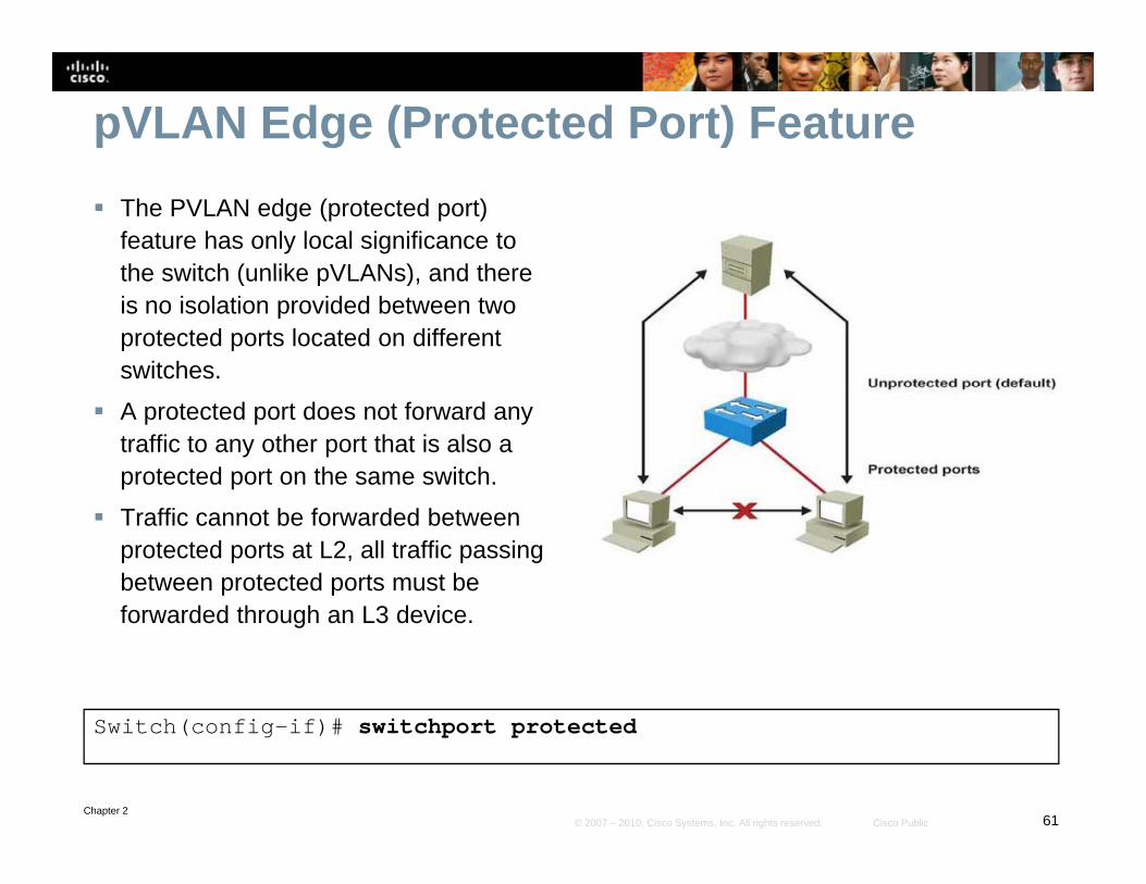
pVLAN Edge (Protected Port) Feature The PVLAN edge (protected port)
feature has only local significance to the switch (unlike pVLANs) and therethe switch (unlike pVLANs), and there is no isolation provided between two protected ports located on different switches.
A protected port does not forward any traffic to any other port that is also a protected port on the same switch.
Traffic cannot be forwarded between protected ports at L2, all traffic passing between protected ports must be f d d th h L3 d iforwarded through an L3 device.
S it h( fi if)# it h t t t d
Chapter 261© 2007 – 2010, Cisco Systems, Inc. All rights reserved. Cisco Public
Switch(config-if)# switchport protected

Configuring LinkConfiguring Link Aggregation with Etherchannel
Chapter 262© 2007 – 2010, Cisco Systems, Inc. All rights reserved. Cisco Public

EtherChannel Technology Up to 8 physical links can be
bundled into a single logical EtherChannel linkEtherChannel link. Usually EtherChannel is used for
trunk links. Configuration applied to port channel
interface affects all physical interfaces assigned to the port g pchannel. Load balancing takes place between
the physical links in anthe physical links in an EtherChannel. EtherChannels can be L2 or L3
i t f
Chapter 263© 2007 – 2010, Cisco Systems, Inc. All rights reserved. Cisco Public
interfaces.

EtherChannel Management Protocols Port Aggregation Protocol (PAgP) is a Cisco-proprietary protocol that aids in
the automatic creation of Fast EtherChannel links. • When an EtherChannel link is configured using PAgP PAgP packets are sent between• When an EtherChannel link is configured using PAgP, PAgP packets are sent between
Fast EtherChannel-capable ports to negotiate the forming of a channel.
• When PAgP identifies matched Ethernet links, it groups the links into an EtherChannel. Spanning tree adds the EtherChannel as a single bridge port.g g
Link Aggregation Control Protocol (LACP) is part of an IEEE specification (802.3ad) that also enables several physical ports to be bundled together to form an EtherChannelform an EtherChannel. • LACP enables a switch to negotiate an automatic bundle by sending LACP packets to
the peer.
• It performs a similar function as PAgP with Cisco EtherChannel• It performs a similar function as PAgP with Cisco EtherChannel.
• Because LACP is an IEEE standard, you can use it to facilitate EtherChannels in mixed-switch environments. In a Cisco environment, both protocols are supported.
Chapter 264© 2007 – 2010, Cisco Systems, Inc. All rights reserved. Cisco Public

PAgP Modes
Mode Purpose
Auto Places an interface in a passive negotiating state in which the interface responds to the PAgP packets that it receives but does not initiate PAgP negotiation (default)PAgP packets that it receives but does not initiate PAgP negotiation (default).
Desirable Places an interface in an active negotiating state in which the interface initiates negotiations with other interfaces by sending PAgP packets. Interfaces configured in the “on” mode do not exchange PAgP packets.
On Forces the interface to channel without PAgP.
Non-silent If a switch is connected to a partner that is PAgP-capable, configure the switch interface for non-silent operation. The non-silent keyword is always used with the auto or desirable mode. If you do not specify non-silent with the auto or desirable mode silent is assumed The silent
Chapter 265© 2007 – 2010, Cisco Systems, Inc. All rights reserved. Cisco Public
If you do not specify non silent with the auto or desirable mode, silent is assumed. The silent setting is for connections to file servers or packet analyzers; this setting enables PAgP to operate, to attach the interface to a channel group, and to use the interface for transmission.

LACP Modes
Mode Purpose
Passive Places a port in a passive negotiating state. In this state, the port responds to the LACP packets that it receives but does not initiate LACP packet negotiation (default).
Active Places a port in an active negotiating state. In this state, the port initiates negotiations with other ports by sending LACP packets.
Chapter 266© 2007 – 2010, Cisco Systems, Inc. All rights reserved. Cisco Public
negotiations with other ports by sending LACP packets. On Forces the interface to the channel without PAgP or LACP.
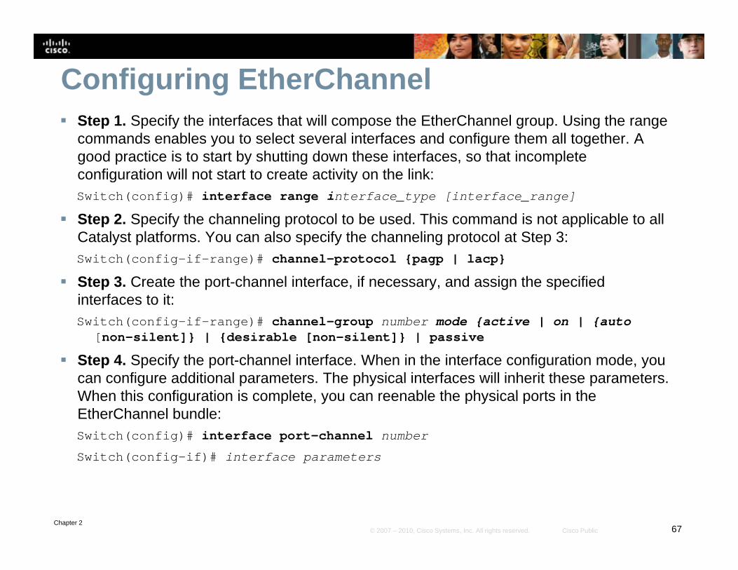
Configuring EtherChannel Step 1. Specify the interfaces that will compose the EtherChannel group. Using the range
commands enables you to select several interfaces and configure them all together. A good practice is to start by shutting down these interfaces, so that incomplete configuration will not start to create activity on the link:configuration will not start to create activity on the link:Switch(config)# interface range interface_type [interface_range]
Step 2. Specify the channeling protocol to be used. This command is not applicable to all Catalyst platforms. You can also specify the channeling protocol at Step 3:Switch(config-if-range)# channel-protocol {pagp | lacp}
Step 3. Create the port-channel interface, if necessary, and assign the specified interfaces to it:Switch(config if range)# channel-group number mode {active | on | {autoSwitch(config-if-range)# channel-group number mode {active | on | {auto
[non-silent]} | {desirable [non-silent]} | passive
Step 4. Specify the port-channel interface. When in the interface configuration mode, you can configure additional parameters. The physical interfaces will inherit these parameters. When this config ration is complete o can reenable the ph sical ports in theWhen this configuration is complete, you can reenable the physical ports in the EtherChannel bundle:Switch(config)# interface port-channel number
Switch(config-if)# interface parameters
Chapter 267© 2007 – 2010, Cisco Systems, Inc. All rights reserved. Cisco Public

Example: EtherChannel ConfigurationSwitch(config)# interface fastethernet 0/23Switch(config-if)# channel-group 2 mode activeSwitch(config)# interface fastethernet 0/24Switch(config if)# channel group 2 mode activeSwitch(config-if)# channel-group 2 mode activeSwitch(config)# interface port-channel 2Switch(config-if)# switchport mode trunkSwitch(config-if)# switchport trunk native VLAN 99Switch(config if)# switchport trunk allowed VLAN 2 3 99Switch(config-if)# switchport trunk allowed VLAN 2,3,99
Remote Switch configuration
RSwitch(config)# interface fastethernet 0/23RSwitch(config)# interface fastethernet 0/23RSwitch(config-if)# channel-group 5 mode onRSwitch(config)# interface fastethernet 0/24RSwitch(config-if)# channel-group 5 mode onRSwitch(config)# interface port-channel 5
Chapter 268© 2007 – 2010, Cisco Systems, Inc. All rights reserved. Cisco Public
RSwitch(config)# interface port channel 5RSwitch(config-if)# switchport mode trunkRSwitch(config-if)# switchport trunk native VLAN 99

Verifying EtherChannel (1)
You can use several commands to verify an EtherChannel configuration. On any physical interface member of an EtherChannel bundle the h i t f i t f id th h lbundle, the show interfaces interface_id etherchannelcommand provides information on the role of the interface in the EtherChannel. I t f F tEth t 0/24 b l i t f Eth Ch l b dl 1 Interface FastEthernet 0/24 below is part of EtherChannel bundle 1.
The protocol for this EtherChannel is LACP.
S it h# show interfaces fa0/24 etherchannelSwitch# show interfaces fa0/24 etherchannelPort state = Up Sngl-port-Bndl Mstr Not-in-BndlChannel group = 1 Mode = Active Gcchange = -Port-channel = null GC = - Pseudo port-channel = Po1Port index = 0 Load = 0x00 Protocol = LACP
Chapter 269© 2007 – 2010, Cisco Systems, Inc. All rights reserved. Cisco Public

Verifying EtherChannel (2) The show etherchannel number port-channel command can
be used to display information about a specific port-channel. Below Port-channel 1 consists of two physical ports, Fa0/23 andBelow Port channel 1 consists of two physical ports, Fa0/23 and
Fa0/24. It uses LACP in active mode. It is properly connected to another switch with a compatible It is properly connected to another switch with a compatible
configuration.This is why the port-channel is said to be in use.
Switch# show etherchannel 1 port-channelSwitch# show etherchannel 1 port channelPort-channels in the group:---------------------------
Port-channel: Po7 (Primary Aggregator)Age of the Port-channel = 195d:03h:10m:44sLogical slot/port = 0/1 Number of ports = 2Port state = Port-channel Ag-InuseProtocol = LACP
Ports in the Port-channel:Index Load Port EC state No of bits
+ + + +
Chapter 270© 2007 – 2010, Cisco Systems, Inc. All rights reserved. Cisco Public
------+------+--------+--------------+-----------0 55 fa0/23 Active 41 45 fa0/24 Active 4

Verifying EtherChannel (3) When several port-channel interfaces are configured on the same device, the show etherchannel summary command is useful for displaying one-line information per port-channel.
As shown below; the switch has three EtherChannels configured: Groups 2 and 7 use LACP and Group 9 uses PAgP. Each EtherChannel has the member interfaces listed. All three groups are Layer 2 EtherChannels and are all in use (SU next to the port-channel number)(SU next to the port-channel number).
Switch# show etherchannel summaryFlags: D - down P - bundled in port-channelI - stand-alone s - suspendedH - Hot-standby (LACP only)y ( y)R - Layer3 S - Layer2U - in use f - failed to allocate aggregatorM - not in use, minimum links not metu - unsuitable for bundlingw - waiting to be aggregatedd - default portNumber of channel-groups in use: 2Number of aggregators: 2Group Port-channel Protocol Ports------+-------------+-----------+--------------------------------------------2 Po2(SU) LACP g0/49(P) g0/50(P) g0/51(P) g0/52(P)
Chapter 271© 2007 – 2010, Cisco Systems, Inc. All rights reserved. Cisco Public
2 Po2(SU) LACP g0/49(P) g0/50(P) g0/51(P) g0/52(P)7 Po7(SU) LACP g0/47(P) g0/48(P)9 Po9(SU) PAgP g0/8(P) g0/9(P)

Verifying EtherChannel (4) The show running-config interface interface_id command displays sections of your configuration relevant to EtherChannel The interfaceconfiguration relevant to EtherChannel. The interface argument can be physical or logical.
Switch# show running-config interface g0/48Switch# show running config interface g0/48Building configuration...Current configuration : 154 bytesinterface GigabitEthernet0/48switchport access vlan 41switchport trunk encapsulation dot1qswitchport mode trunkchannel-group 7 mode active
i h# h i fi i t f t h l 7Switch# show running-config interface port-channel 7Building configuration...Current configuration : 92 bytesinterface Port-channel7switchport trunk encapsulation dot1q
Chapter 272© 2007 – 2010, Cisco Systems, Inc. All rights reserved. Cisco Public
switchport trunk encapsulation dot1qswitchport mode trunk

EtherChannel Load Balancing
Chapter 273© 2007 – 2010, Cisco Systems, Inc. All rights reserved. Cisco Public

EtherChannel Load Balancing Example Here the EtherChannel load-balancing mechanism is configured to use
source and destination IP address pairs. This rule is applied to IPv4 and IPv6 traffic whereas the non IP load This rule is applied to IPv4 and IPv6 traffic, whereas the non-IP load-
balancing mechanism uses source and destination MAC address pairs. It was observed that with source-destination IP load balancing, the
balancing ends up more like 70-30 on the links!
Switch(config)# port channel load balance src dst ipSwitch(config)# port-channel load-balance src-dst-ipSwitch(config)# exitSwitch# show etherchannel load-balanceEtherChannel Load-Balancing Configuration:src-dst-ipEtherChannel Load-Balancing Addresses Used Per-Protocol:Non-IP: Source XOR Destination MAC addressIPv4: Source XOR Destination IP address
Chapter 274© 2007 – 2010, Cisco Systems, Inc. All rights reserved. Cisco Public
IPv4: Source XOR Destination IP addressIPv6: Source XOR Destination IP address

Chapter 2 Summary A VLAN is a logical grouping of switch ports independent of physical location. Local
VLANs are now recommended over end-to-end VLAN implementations.
A trunk is a Layer 2 point to point link between networking devices carry the traffic of A trunk is a Layer 2 point-to-point link between networking devices carry the traffic of multiple VLANs.
ISL and 802.1Q are the two trunking protocols that can connect two switches.
VTP i d t di t ib t d h i i f ti b t VLAN fi d th h t VTP is used to distribute and synchronize information about VLANs configured throughout a switched network.
VTP pruning helps to stop flooding of unnecessary traffic on trunk links.
Device communication within the same VLAN can be fine-tuned using pVLANs. A pVLAN is associated to a primary VLAN, and then mapped to one or several ports. A primary VLAN can map to one isolated and several community VLANs. pVLANs can span across several switches using regular 802 1q trunks or pVLAN trunksseveral switches using regular 802.1q trunks or pVLAN trunks.
Use EtherChannel by aggregating individual, similar links between switches. EtherChannel can be dynamically configured between switches using either the Cisco-proprietary PAgP or the IEEE 802 3ad LACP EtherChannel load balances traffic over all
Chapter 275© 2007 – 2010, Cisco Systems, Inc. All rights reserved. Cisco Public
proprietary PAgP or the IEEE 802.3ad LACP. EtherChannel load balances traffic over all the links in the bundle. The method that is chosen directly impacts the efficiency of this load-balancing mechanism.

Chapter 2 Labs Lab 2-1 Static VLANS, VLAN Trunking, and VTP Domains Lab 2-2 Configuring EtherChannel
Chapter 276© 2007 – 2010, Cisco Systems, Inc. All rights reserved. Cisco Public

Resources Catalyst 3560 Switch Command Reference
www.cisco.com/en/US/docs/switches/lan/catalyst3560/softw/ l /12 2 52 / d/ f /3560 ht lare/release/12.2_52_se/command/reference/3560cr.html
Chapter 277© 2007 – 2010, Cisco Systems, Inc. All rights reserved. Cisco Public

Chapter 278© 2007 – 2010, Cisco Systems, Inc. All rights reserved. Cisco Public