Embed Size (px)
Citation preview
Fundamentals of Power Electronics Chapter 2: Principles of steady-state converter analysis1
Chapter 2 Principles of Steady-State Converter Analysis
2.1. Introduction
2.2. Inductor volt-second balance, capacitor charge balance, and the small ripple approximation
2.3. Boost converter example
2.4. Cuk converter example
2.5. Estimating the ripple in converters containing two-pole low-pass filters
2.6. Summary of key points
Fundamentals of Power Electronics Chapter 2: Principles of steady-state converter analysis2
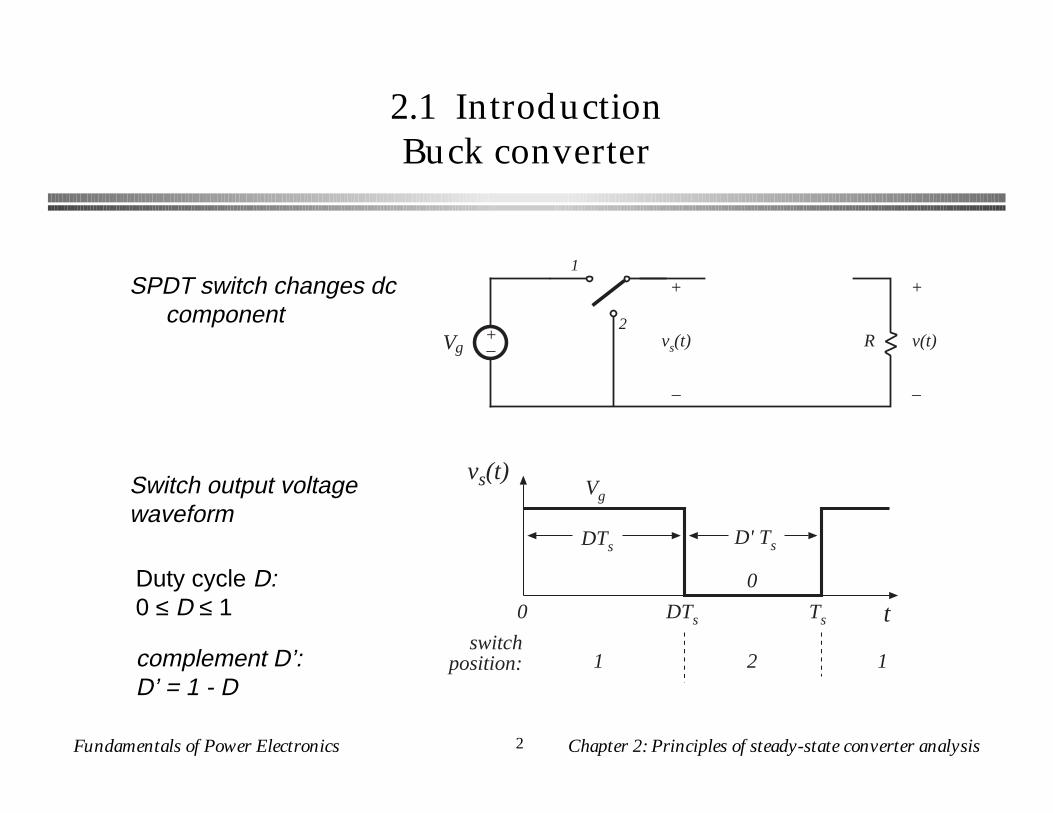
2.1 IntroductionBuck converter
SPDT switch changes dc component
+–Vg R
+
v(t)
–
1
2
+
vs(t)
–
vs(t) Vg
DTs D' Ts
0
t0 DTs Ts
switchposition: 1 2 1
Switch output voltage waveform
complement D’:D’ = 1 - D
Duty cycle D:0 ≤ D ≤ 1

Fundamentals of Power Electronics Chapter 2: Principles of steady-state converter analysis3
Dc component of switch output voltage
vs(t) Vg
0
t0 DTs Ts
<vs> = DVgarea =DTsVg
vs = 1Ts
vs(t) dt0
Ts
vs = 1Ts
(DTsVg) = DVg
Fourier analysis: Dc component = average value
Fundamentals of Power Electronics Chapter 2: Principles of steady-state converter analysis4
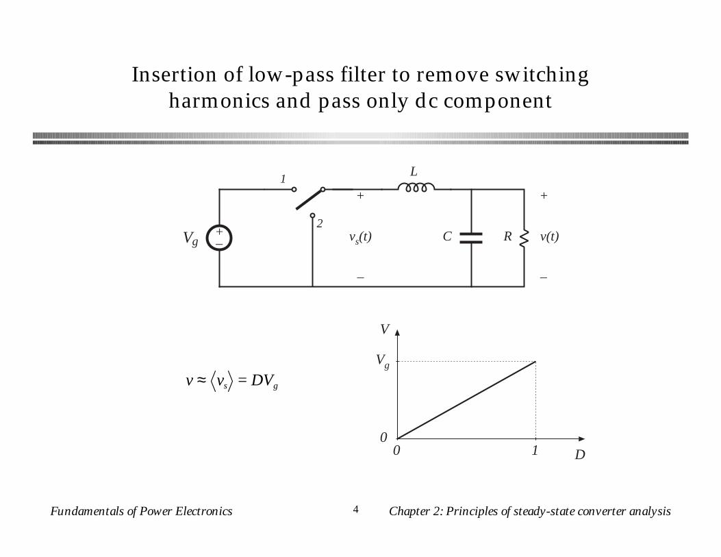
Insertion of low-pass filter to remove switching harmonics and pass only dc component
+–Vg
L
C R
+
v(t)
–
1
2
+
vs(t)
–
Vg
00 D
V
1
v ≈ vs = DVg
Fundamentals of Power Electronics Chapter 2: Principles of steady-state converter analysis5
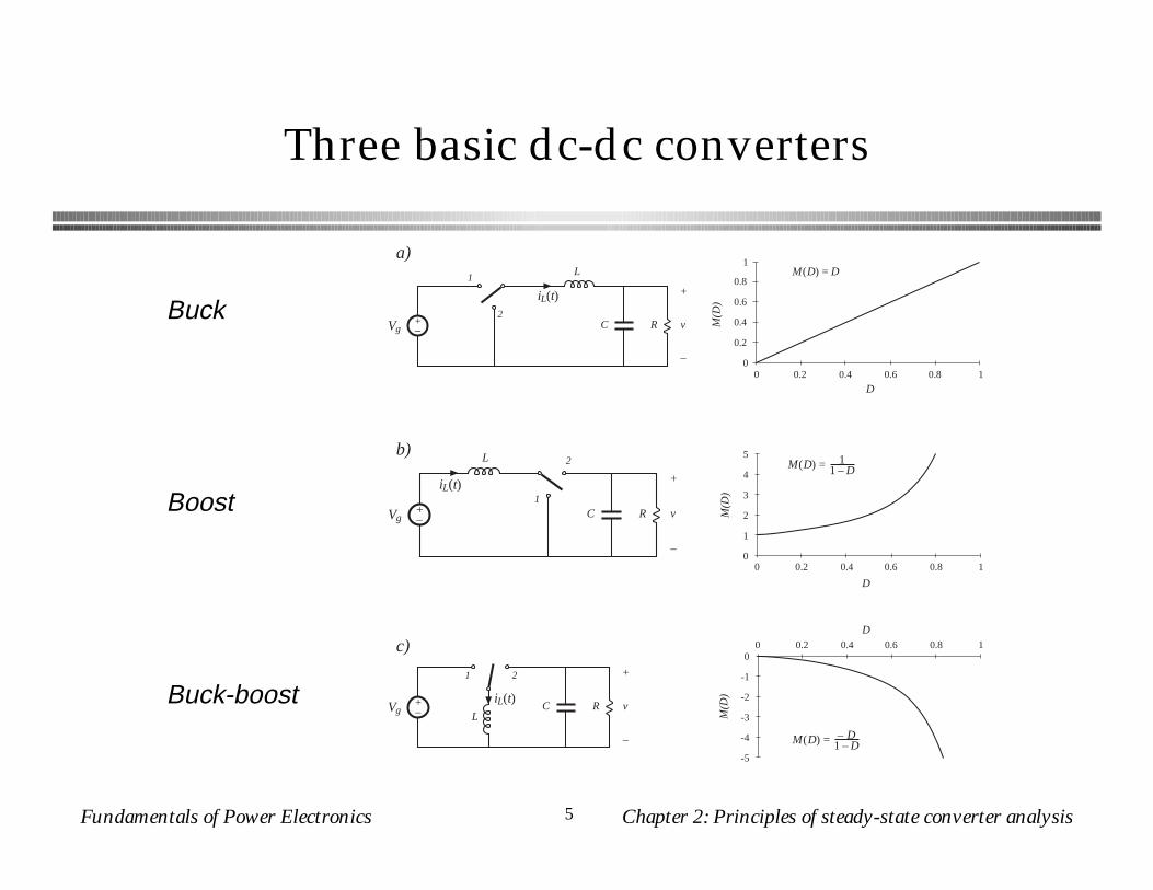
Three basic dc-dc converters
M(D
)
D
0
0.2
0.4
0.6
0.8
1
0 0.2 0.4 0.6 0.8 1
M(D
)
D
0
1
2
3
4
5
0 0.2 0.4 0.6 0.8 1
M(D
)
D
-5
-4
-3
-2
-1
00 0.2 0.4 0.6 0.8 1
a)
b)
c)
+–Vg
iL(t)
L
C R
+
v
–
1
2
+–Vg
iL(t)
L
C R
+
v
–
1
2
+–Vg
iL(t)L
C R
+
v
–
1 2
M(D) = D
M(D) = 11 –D
M(D) = – D1 –D
Buck
Boost
Buck-boost
Fundamentals of Power Electronics Chapter 2: Principles of steady-state converter analysis6
Objectives of this chapter
● Develop techniques for easily determining output voltage of an arbitrary converter circuit
● Derive the principles of inductor volt-second balance and capacitor charge (amp-second) balance
● Introduce the key small ripple approximation● Develop simple methods for selecting filter element
values● Illustrate via examples
Fundamentals of Power Electronics Chapter 2: Principles of steady-state converter analysis7
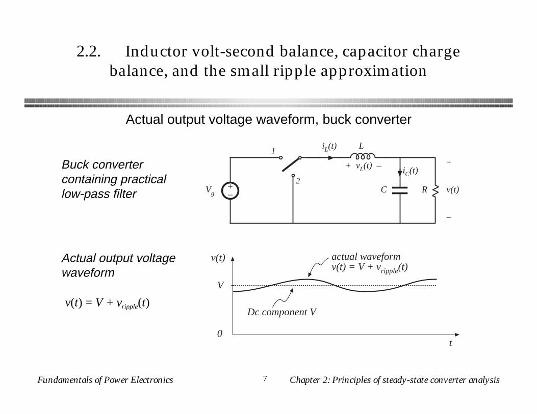
2.2. Inductor volt-second balance, capacitor charge balance, and the small ripple approximation
+–
L
C R
+
v(t)
–
1
2
iL(t)
+ vL(t) – iC(t)
Vg
v(t)
t0
V
actual waveformv(t) = V + vripple(t)
Dc component V
Buck converter containing practical low-pass filter
Actual output voltage waveform
v(t) = V + vripple(t)
Actual output voltage waveform, buck converter
Fundamentals of Power Electronics Chapter 2: Principles of steady-state converter analysis8
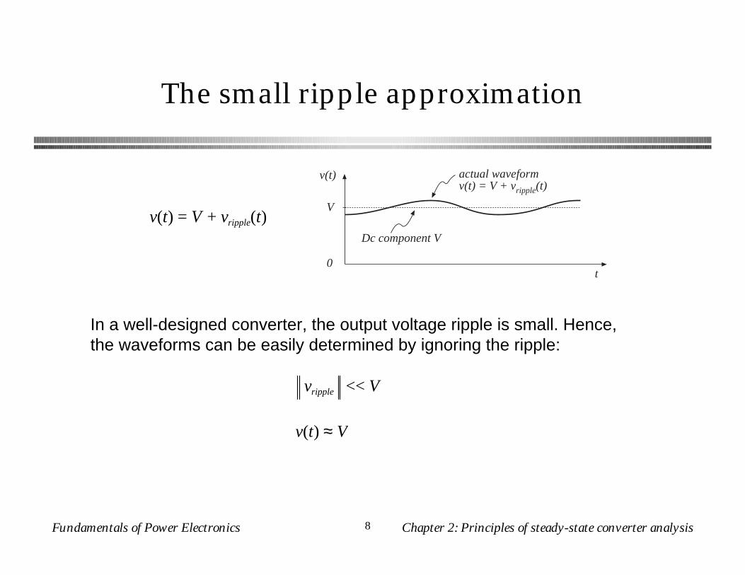
The small ripple approximation
v(t)
t0
V
actual waveformv(t) = V + vripple(t)
Dc component V
In a well-designed converter, the output voltage ripple is small. Hence, the waveforms can be easily determined by ignoring the ripple:
vripple << V
v(t) ≈ V
v(t) = V + vripple(t)
Fundamentals of Power Electronics Chapter 2: Principles of steady-state converter analysis9
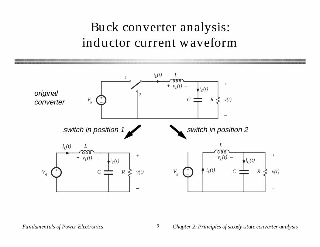
Buck converter analysis:inductor current waveform
+–
L
C R
+
v(t)
–
1
2
iL(t)
+ vL(t) – iC(t)
Vg
L
C R
+
v(t)
–
iL(t)
+ vL(t) – iC(t)
+–Vg
L
C R
+
v(t)
–
iL(t)
+ vL(t) – iC(t)
+–Vg
originalconverter
switch in position 2switch in position 1
Fundamentals of Power Electronics Chapter 2: Principles of steady-state converter analysis10
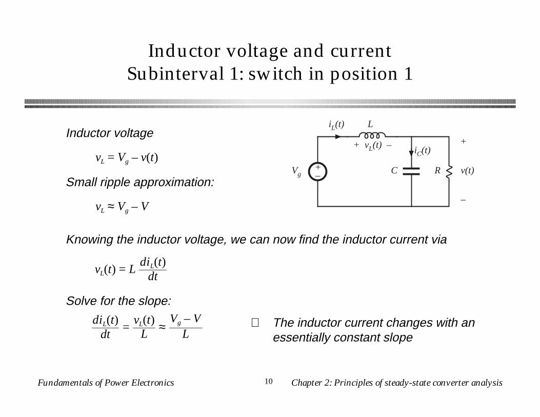
Inductor voltage and currentSubinterval 1: switch in position 1
L
C R
+
v(t)
–
iL(t)
+ vL(t) – iC(t)
+–Vg
vL = Vg – v(t)
Inductor voltage
Small ripple approximation:
vL ≈ Vg – V
Knowing the inductor voltage, we can now find the inductor current via
vL(t) = LdiL(t)
dt
Solve for the slope:
diL(t)dt
=vL(t)
L ≈Vg – V
L⇒ The inductor current changes with an
essentially constant slope
Fundamentals of Power Electronics Chapter 2: Principles of steady-state converter analysis11
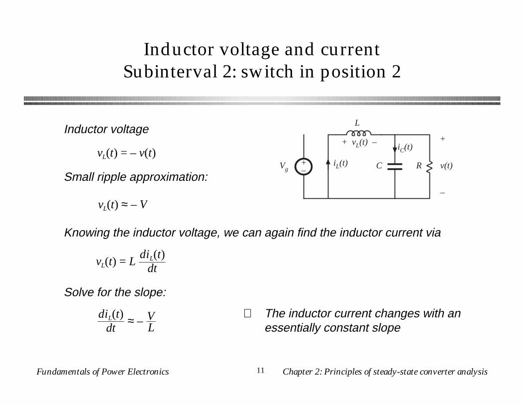
Inductor voltage and currentSubinterval 2: switch in position 2
Inductor voltage
Small ripple approximation:
Knowing the inductor voltage, we can again find the inductor current via
vL(t) = LdiL(t)
dt
Solve for the slope:
⇒ The inductor current changes with an essentially constant slope
L
C R
+
v(t)
–
iL(t)
+ vL(t) – iC(t)
+–Vg
vL(t) = – v(t)
vL(t) ≈ – V
diL(t)dt
≈ – VL
Fundamentals of Power Electronics Chapter 2: Principles of steady-state converter analysis12
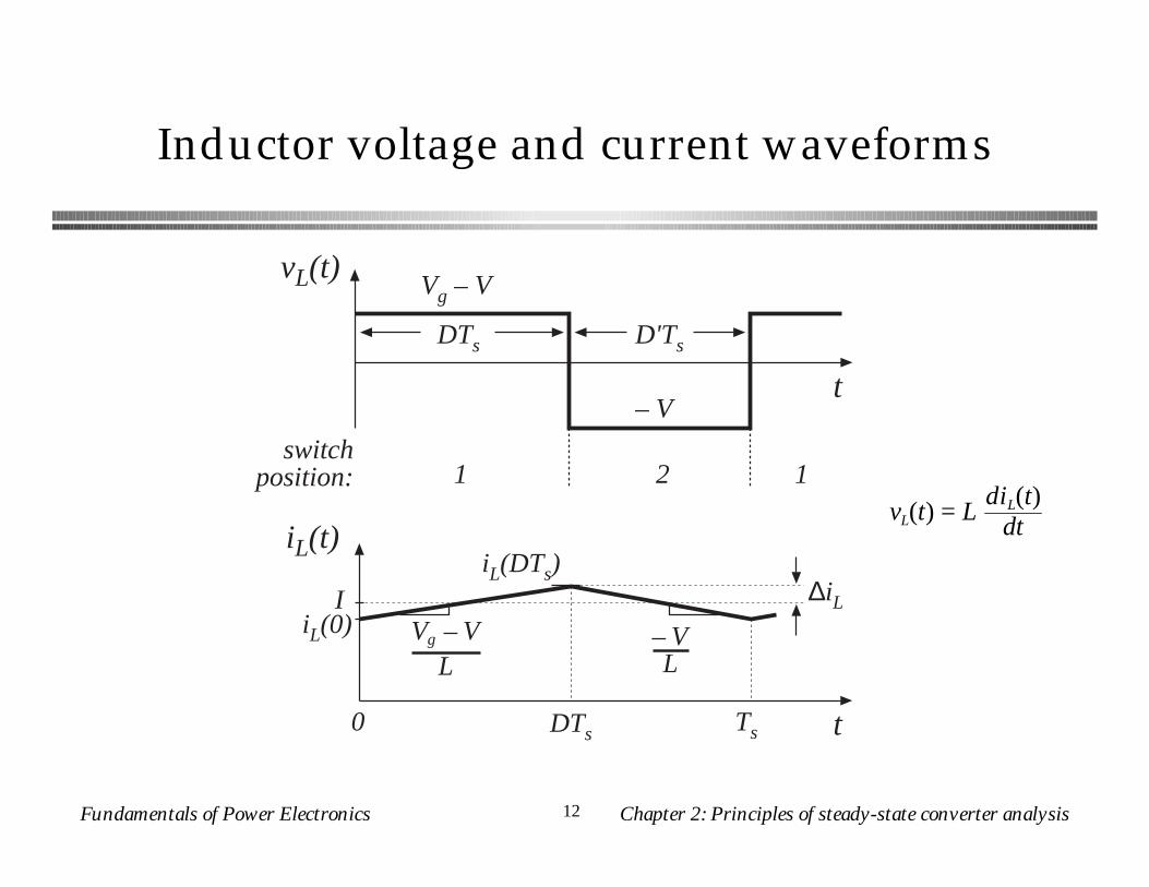
Inductor voltage and current waveforms
iL(t)
t0 DTs Ts
IiL(0) Vg – V
L
iL(DTs)∆iL
– VL
vL(t)Vg – V
t– V
D'TsDTs
switchposition: 1 2 1
vL(t) = LdiL(t)
dt
Fundamentals of Power Electronics Chapter 2: Principles of steady-state converter analysis13
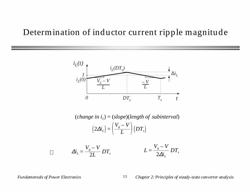
Determination of inductor current ripple magnitude
iL(t)
t0 DTs Ts
IiL(0) Vg – V
L
iL(DTs)∆iL
– VL
(change in iL) = (slope)(length of subinterval)
2∆iL =Vg – V
L DTs
∆iL =Vg – V
2LDTs
L =Vg – V
2∆iL
DTs⇒
Fundamentals of Power Electronics Chapter 2: Principles of steady-state converter analysis14
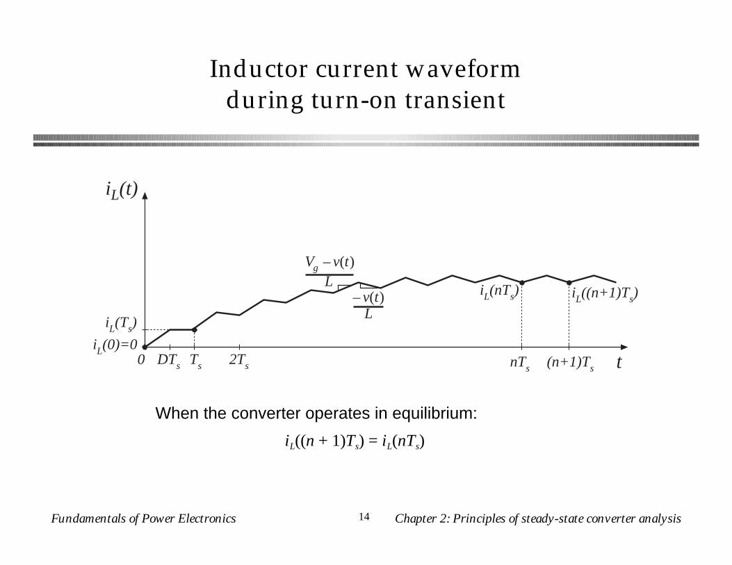
Inductor current waveformduring turn-on transient
iL(t)
t0 DTs Ts
iL(0)=0
iL(nTs)
iL(Ts)
Vg –v(t)L
–v(t)L
2Ts nTs (n+1)Ts
iL((n+1)Ts)
When the converter operates in equilibrium:
iL((n + 1)Ts) = iL(nTs)
Fundamentals of Power Electronics Chapter 2: Principles of steady-state converter analysis15
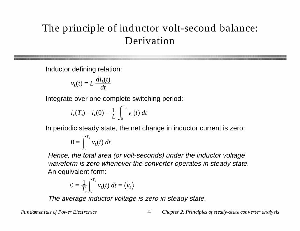
The principle of inductor volt-second balance:Derivation
Inductor defining relation:
Integrate over one complete switching period:
In periodic steady state, the net change in inductor current is zero:
Hence, the total area (or volt-seconds) under the inductor voltage waveform is zero whenever the converter operates in steady state.An equivalent form:
The average inductor voltage is zero in steady state.
vL(t) = LdiL(t)
dt
iL(Ts) – iL(0) = 1L vL(t) dt
0
Ts
0 = vL(t) dt0
Ts
0 = 1Ts
vL(t) dt0
Ts
= vL
Fundamentals of Power Electronics Chapter 2: Principles of steady-state converter analysis16
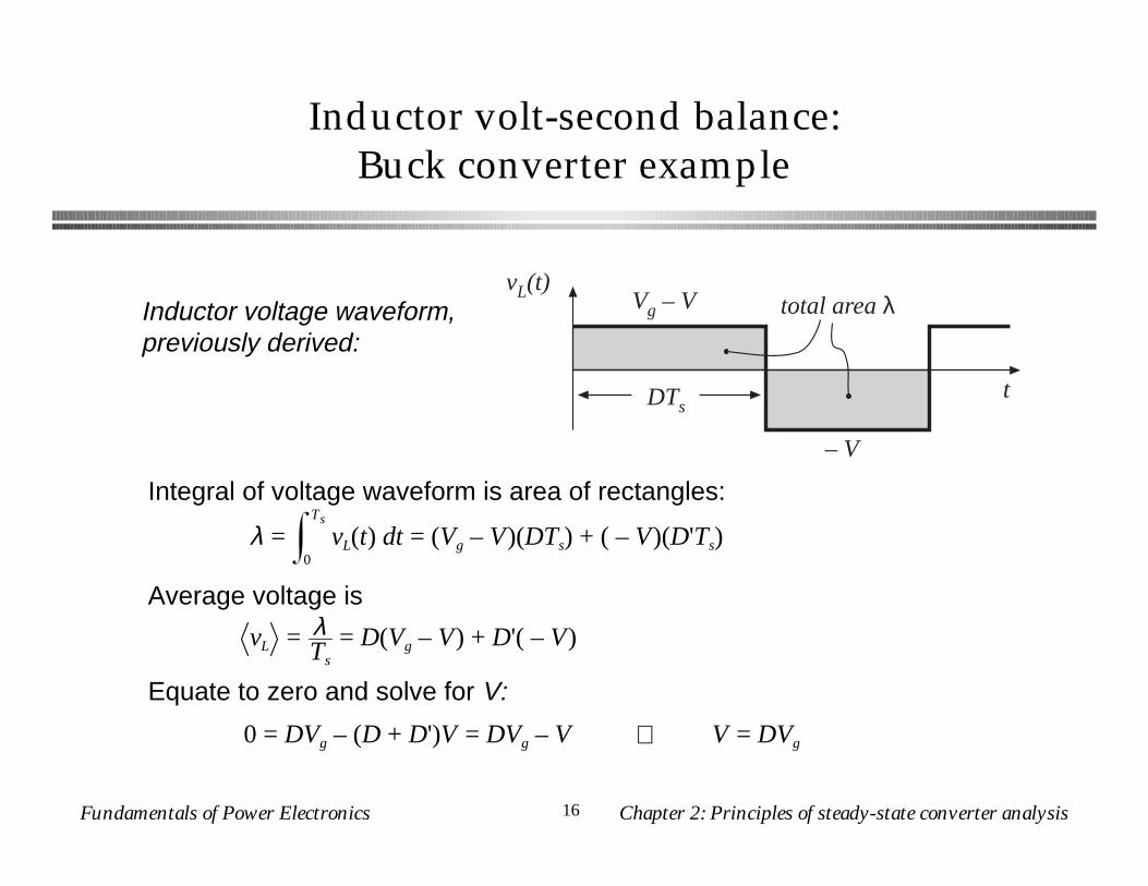
Inductor volt-second balance:Buck converter example
vL(t) Vg – V
t
– V
DTs
total area λInductor voltage waveform, previously derived:
Integral of voltage waveform is area of rectangles:
λ = vL(t) dt0
Ts
= (Vg – V)(DTs) + ( – V)(D'Ts)
Average voltage is
vL = λTs
= D(Vg – V) + D'( – V)
Equate to zero and solve for V:
0 = DVg – (D + D')V = DVg – V ⇒ V = DVg
Fundamentals of Power Electronics Chapter 2: Principles of steady-state converter analysis17
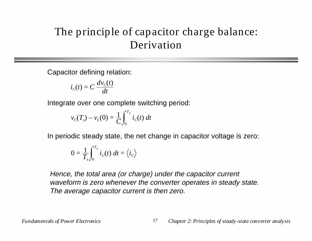
The principle of capacitor charge balance:Derivation
Capacitor defining relation:
Integrate over one complete switching period:
In periodic steady state, the net change in capacitor voltage is zero:
Hence, the total area (or charge) under the capacitor current waveform is zero whenever the converter operates in steady state. The average capacitor current is then zero.
iC(t) = CdvC(t)
dt
vC(Ts) – vC(0) = 1C
iC(t) dt0
Ts
0 = 1Ts
iC(t) dt0
Ts
= iC
Fundamentals of Power Electronics Chapter 2: Principles of steady-state converter analysis18
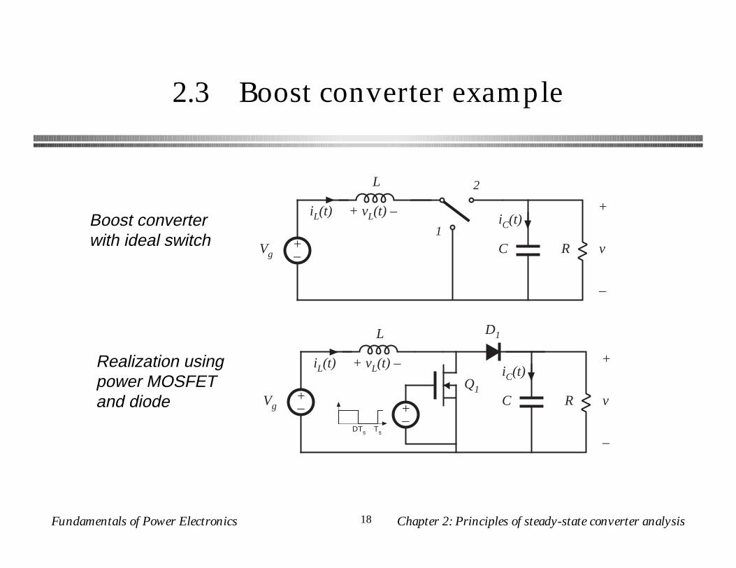
2.3 Boost converter example
+–
L
C R
+
v
–
1
2
iL(t)
Vg
iC(t)+ vL(t) –
+–
L
C R
+
v
–
iL(t)
Vg
iC(t)+ vL(t) –
D1
Q1
DTs Ts
+–
Boost converter with ideal switch
Realization using power MOSFET and diode
Fundamentals of Power Electronics Chapter 2: Principles of steady-state converter analysis19
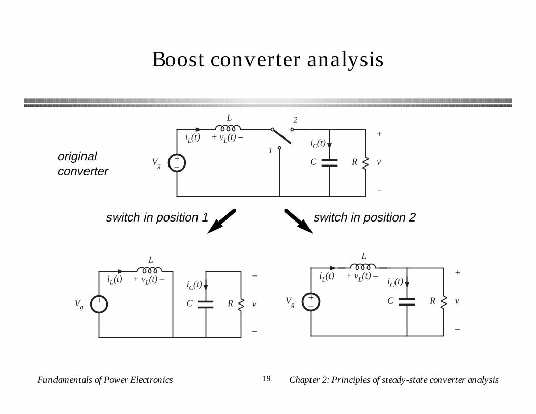
Boost converter analysis
originalconverter
switch in position 2switch in position 1
+–
L
C R
+
v
–
1
2
iL(t)
Vg
iC(t)+ vL(t) –
C R
+
v
–
iC(t)
+–
L
iL(t)
Vg
+ vL(t) –
C R
+
v
–
iC(t)
+–
L
iL(t)
Vg
+ vL(t) –
Fundamentals of Power Electronics Chapter 2: Principles of steady-state converter analysis20
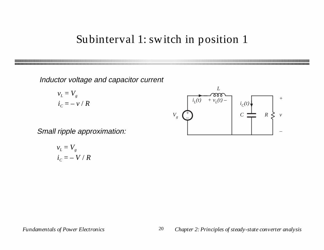
Subinterval 1: switch in position 1
Inductor voltage and capacitor current
Small ripple approximation:
C R
+
v
–
iC(t)
+–
L
iL(t)
Vg
+ vL(t) –vL = Vg
iC = – v / R
vL = Vg
iC = – V / R
Fundamentals of Power Electronics Chapter 2: Principles of steady-state converter analysis21
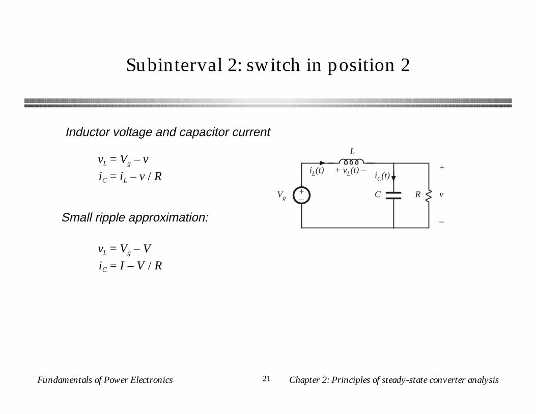
Subinterval 2: switch in position 2
Inductor voltage and capacitor current
Small ripple approximation:
C R
+
v
–
iC(t)
+–
L
iL(t)
Vg
+ vL(t) –vL = Vg – v
iC = iL – v / R
vL = Vg – V
iC = I – V / R
Fundamentals of Power Electronics Chapter 2: Principles of steady-state converter analysis22
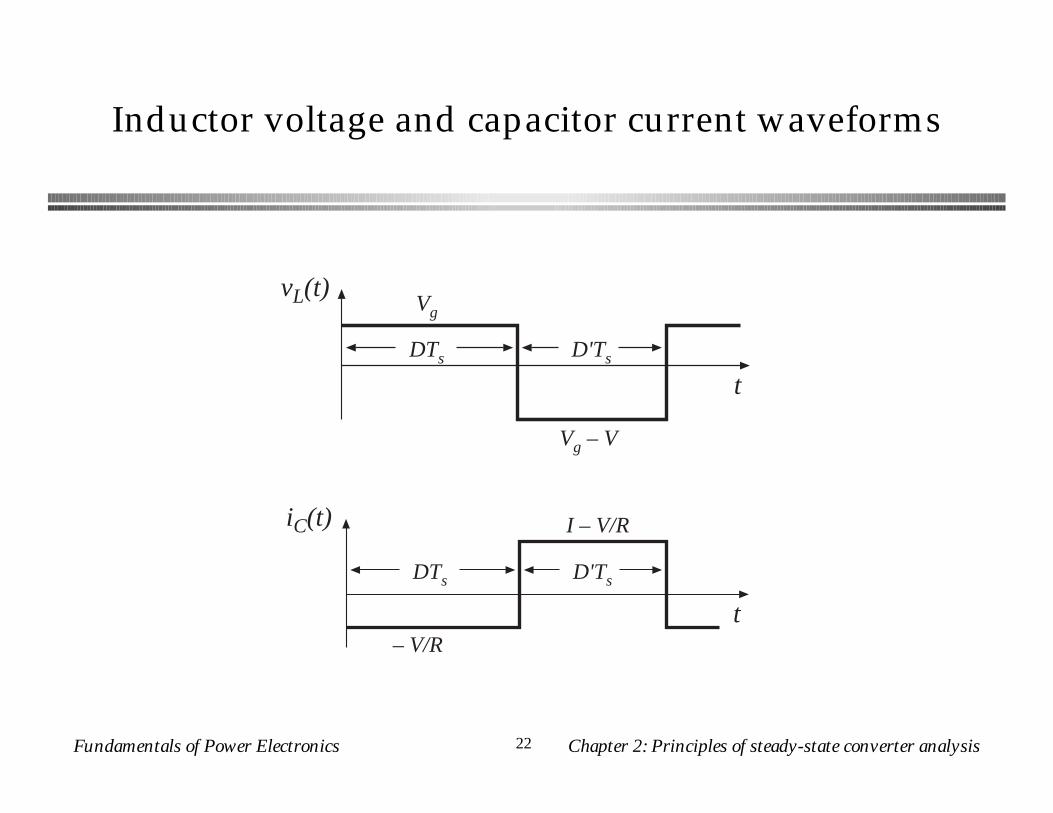
Inductor voltage and capacitor current waveforms
vL(t)
Vg – V
t
DTs
Vg
D'Ts
iC(t)
– V/Rt
DTs
I – V/R
D'Ts
Fundamentals of Power Electronics Chapter 2: Principles of steady-state converter analysis23
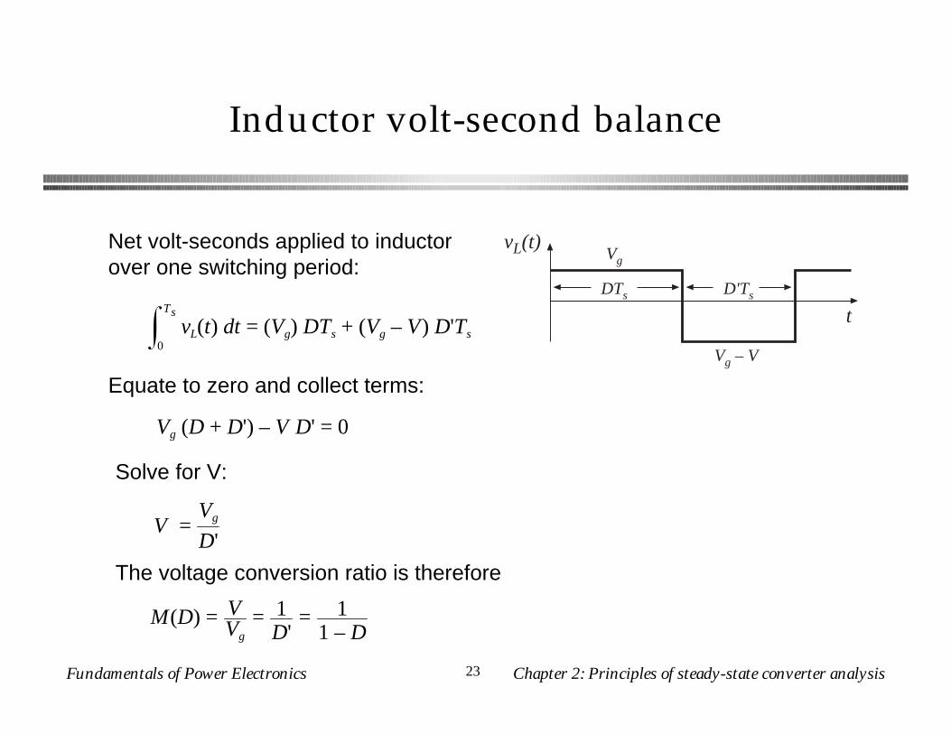
Inductor volt-second balance
vL(t)
Vg – V
t
DTs
Vg
D'Ts
Net volt-seconds applied to inductor over one switching period:
vL(t) dt0
Ts
= (Vg) DTs + (Vg – V) D'Ts
Equate to zero and collect terms:
Vg (D + D') – V D' = 0
Solve for V:
V =Vg
D'
The voltage conversion ratio is therefore
M(D) = VVg
= 1D'
= 11 – D
Fundamentals of Power Electronics Chapter 2: Principles of steady-state converter analysis24
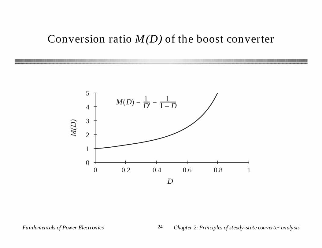
Conversion ratio M(D) of the boost converter
M(D
)
D
0
1
2
3
4
5
0 0.2 0.4 0.6 0.8 1
M(D) = 1D' = 1
1 – D
Fundamentals of Power Electronics Chapter 2: Principles of steady-state converter analysis25
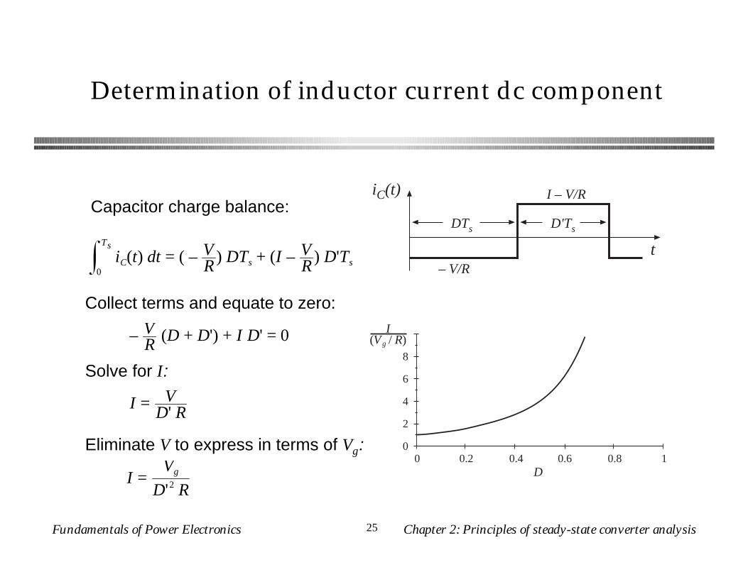
Determination of inductor current dc component
iC(t)
– V/Rt
DTs
I – V/R
D'Ts
Capacitor charge balance:
iC(t) dt0
Ts
= ( – VR ) DTs + (I – V
R ) D'Ts
Collect terms and equate to zero:
– VR (D + D') + I D' = 0
Solve for I:
I = VD' R
I =Vg
D'2 RD
0
2
4
6
8
0 0.2 0.4 0.6 0.8 1
I(Vg / R)
Eliminate V to express in terms of Vg:
Fundamentals of Power Electronics Chapter 2: Principles of steady-state converter analysis26
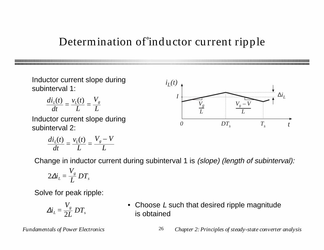
Determination of inductor current ripple
iL(t)
t0 DTs Ts
IVg – V
LVg
L
∆iL
Inductor current slope during subinterval 1:
diL(t)dt
=vL(t)
L =Vg – V
L
Inductor current slope during subinterval 2:
2∆iL =Vg
L DTs
diL(t)dt
=vL(t)
L =Vg
L
Change in inductor current during subinterval 1 is (slope) (length of subinterval):
Solve for peak ripple:
∆iL =Vg
2LDTs
• Choose L such that desired ripple magnitude is obtained
Fundamentals of Power Electronics Chapter 2: Principles of steady-state converter analysis27
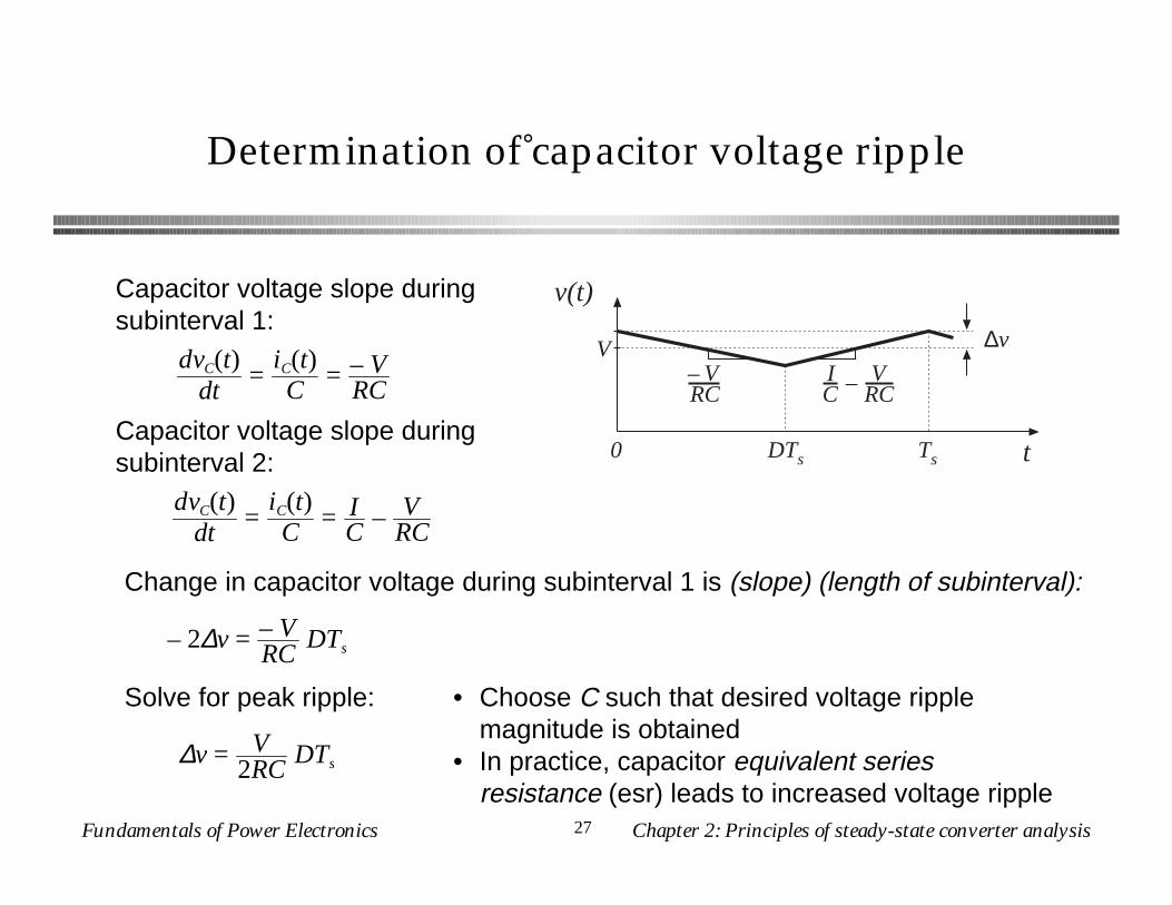
Determination of capacitor voltage ripple
Capacitor voltage slope during subinterval 1:
Capacitor voltage slope during subinterval 2:
Change in capacitor voltage during subinterval 1 is (slope) (length of subinterval):
Solve for peak ripple: • Choose C such that desired voltage ripple magnitude is obtained
• In practice, capacitor equivalent series resistance (esr) leads to increased voltage ripple
v(t)
t0 DTs Ts
V ∆v
– VRC
IC – V
RC
dvC(t)dt
=iC(t)C
= – VRC
dvC(t)dt
=iC(t)C
= IC
– VRC
– 2∆v = – VRC
DTs
∆v = V2RC
DTs
Fundamentals of Power Electronics Chapter 2: Principles of steady-state converter analysis28
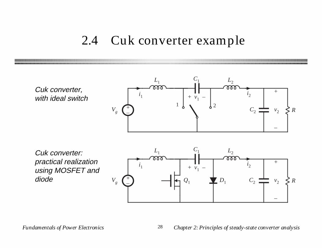
2.4 Cuk converter example
+–
L1
C2 R
+
v2
–
C1 L2
1 2
+ v1 –i1 i2
Vg
+–
L1
C2 R
+
v2
–
C1 L2
+ v1 –i1 i2
D1Q1Vg
Cuk converter, with ideal switch
Cuk converter: practical realization using MOSFET and diode
Fundamentals of Power Electronics Chapter 2: Principles of steady-state converter analysis29
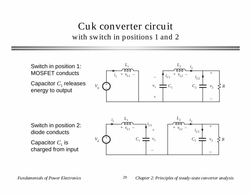
Cuk converter circuitwith switch in positions 1 and 2
+–
L1
C2 R
+
v2
–
C1
L2
i1
i2
–
v1
+
iC1 iC2+ vL2 –+ vL1 –
Vg
+–
L1
C2 R
+
v2
–
C1
L2i1 i2
+
v1
–
iC1
iC2+ vL2 –+ vL1 –
Vg
Switch in position 1: MOSFET conducts
Capacitor C1 releases energy to output
Switch in position 2: diode conducts
Capacitor C1 is charged from input
Fundamentals of Power Electronics Chapter 2: Principles of steady-state converter analysis30
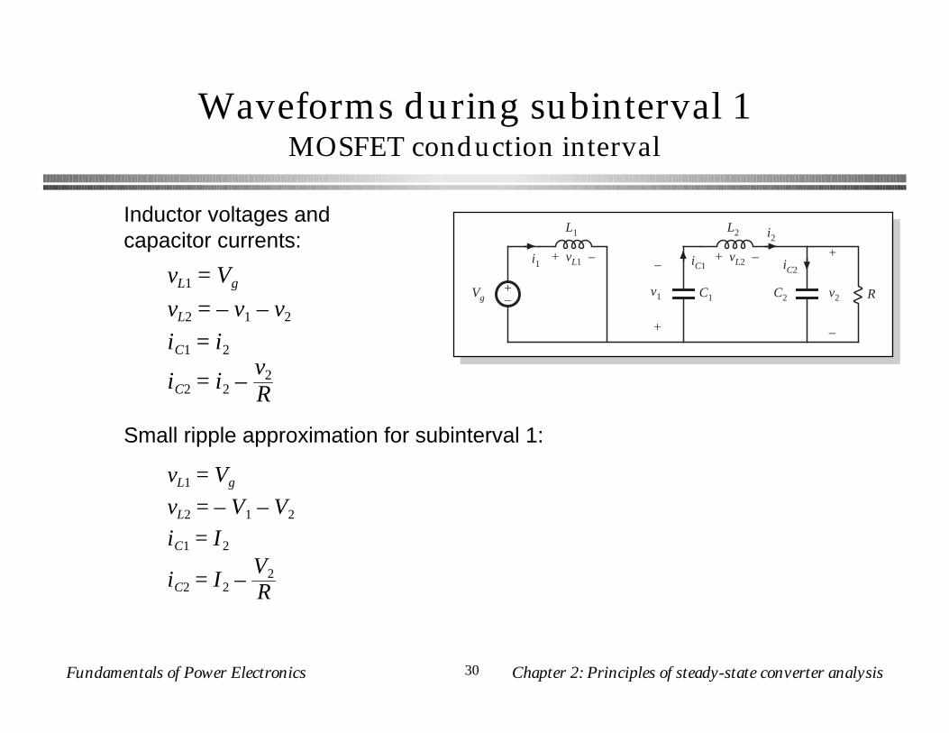
Waveforms during subinterval 1MOSFET conduction interval
+–
L1
C2 R
+
v2
–
C1
L2
i1
i2
–
v1
+
iC1 iC2+ vL2 –+ vL1 –
Vg
vL1 = Vg
vL2 = – v1 – v2
iC1 = i2
iC2 = i2 –v2
R
Inductor voltages and capacitor currents:
Small ripple approximation for subinterval 1:
vL1 = Vg
vL2 = – V1 – V2
iC1 = I2
iC2 = I2 –V2
R
Fundamentals of Power Electronics Chapter 2: Principles of steady-state converter analysis31
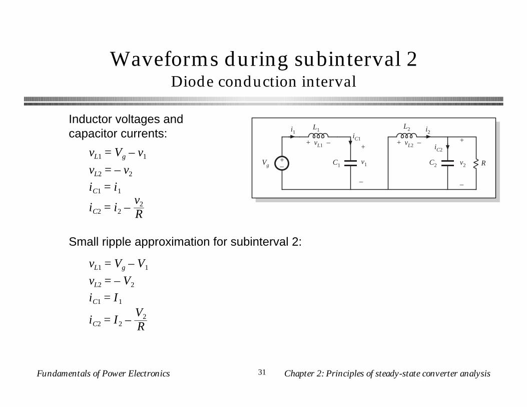
Waveforms during subinterval 2Diode conduction interval
Inductor voltages and capacitor currents:
Small ripple approximation for subinterval 2:
+–
L1
C2 R
+
v2
–
C1
L2i1 i2
+
v1
–
iC1
iC2+ vL2 –+ vL1 –
Vg
vL1 = Vg – v1
vL2 = – v2
iC1 = i1
iC2 = i2 –v2
R
vL1 = Vg – V1
vL2 = – V2
iC1 = I1
iC2 = I2 –V2
R
Fundamentals of Power Electronics Chapter 2: Principles of steady-state converter analysis32
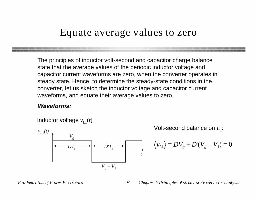
Equate average values to zero
The principles of inductor volt-second and capacitor charge balance state that the average values of the periodic inductor voltage and capacitor current waveforms are zero, when the converter operates in steady state. Hence, to determine the steady-state conditions in the converter, let us sketch the inductor voltage and capacitor current waveforms, and equate their average values to zero.
Waveforms:
vL1(t)
Vg – V1
t
DTs
Vg
D'Ts
Inductor voltage vL1(t)
vL1 = DVg + D'(Vg – V1) = 0
Volt-second balance on L1:
Fundamentals of Power Electronics Chapter 2: Principles of steady-state converter analysis33
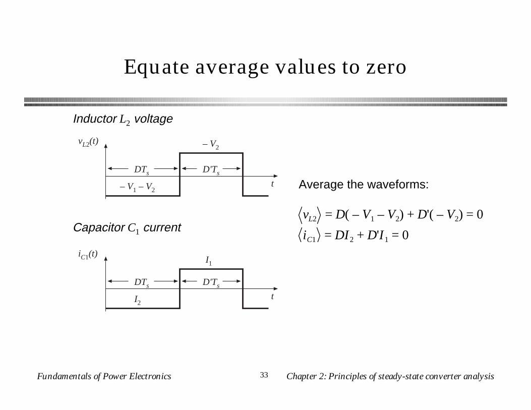
Equate average values to zero
vL2(t)
– V1 – V2t
DTs
– V2
D'Ts
iC1(t)
I2t
DTs
I1
D'Ts
Inductor L2 voltage
Capacitor C1 currentvL2 = D( – V1 – V2) + D'( – V2) = 0
iC1 = DI2 + D'I1 = 0
Average the waveforms:
Fundamentals of Power Electronics Chapter 2: Principles of steady-state converter analysis34
Equate average values to zero
iC2(t)
I2 – V2 / R (= 0)
tDTs D'Ts
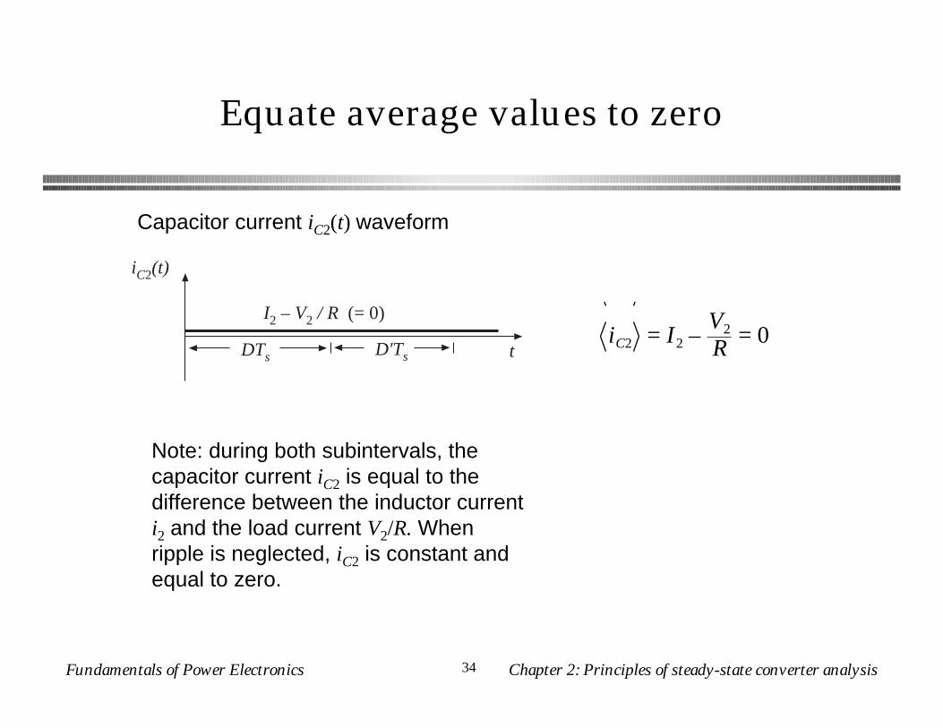
Capacitor current iC2(t) waveform
Note: during both subintervals, the capacitor current iC2 is equal to the difference between the inductor current i2 and the load current V2/R. When ripple is neglected, iC2 is constant and equal to zero.
iC2 = I2 –V2
R = 0
Fundamentals of Power Electronics Chapter 2: Principles of steady-state converter analysis35
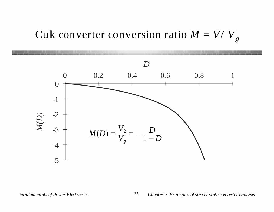
Cuk converter conversion ratio M = V/VgM
(D)
D
-5
-4
-3
-2
-1
00 0.2 0.4 0.6 0.8 1
M(D) =V2
Vg= – D
1 – D
Fundamentals of Power Electronics Chapter 2: Principles of steady-state converter analysis36
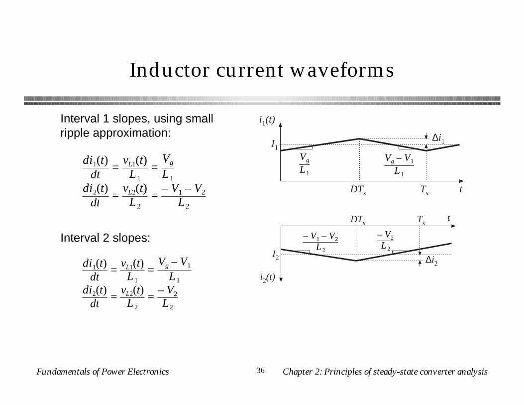
Inductor current waveforms
i1(t)
tDTs Ts
I1∆i1
Vg – V1
L 1
Vg
L 1
– V2
L 2
– V1 – V2
L 2
i2(t)
tDTs Ts
I2 ∆i2
di1(t)dt
=vL1(t)
L1=
Vg
L1
di2(t)dt
=vL2(t)
L2=
– V1 – V2
L2
Interval 1 slopes, using small ripple approximation:
Interval 2 slopes:
di1(t)dt
=vL1(t)
L1=
Vg – V1
L1
di2(t)dt
=vL2(t)
L2=
– V2
L2
Fundamentals of Power Electronics Chapter 2: Principles of steady-state converter analysis37
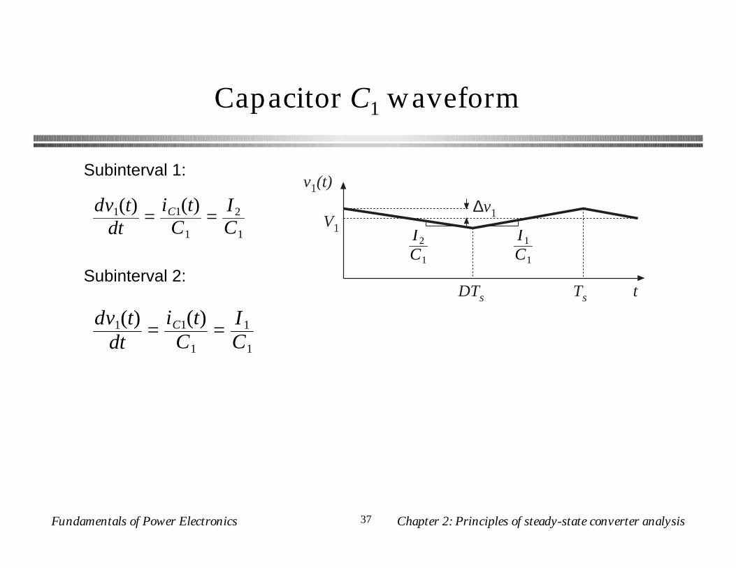
Capacitor C1 waveform
v1(t)
tDTs Ts
V1
∆v1
I1
C1
I2
C1
dv1(t)dt
=iC1(t)C1
=I2
C1
Subinterval 1:
Subinterval 2:
dv1(t)dt
=iC1(t)C1
=I1
C1
Fundamentals of Power Electronics Chapter 2: Principles of steady-state converter analysis38
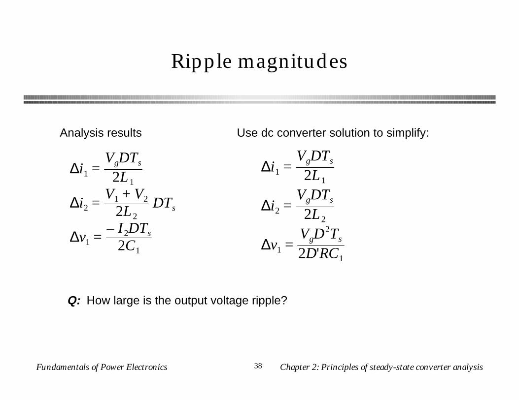
Ripple magnitudes
∆i1 =VgDTs
2L1
∆i2 =V1 + V2
2L2DTs
∆v1 =– I2DTs
2C1
Use dc converter solution to simplify:
∆i1 =VgDTs
2L1
∆i2 =VgDTs
2L2
∆v1 =VgD
2Ts
2D'RC1
Analysis results
Q: How large is the output voltage ripple?
Fundamentals of Power Electronics Chapter 2: Principles of steady-state converter analysis39
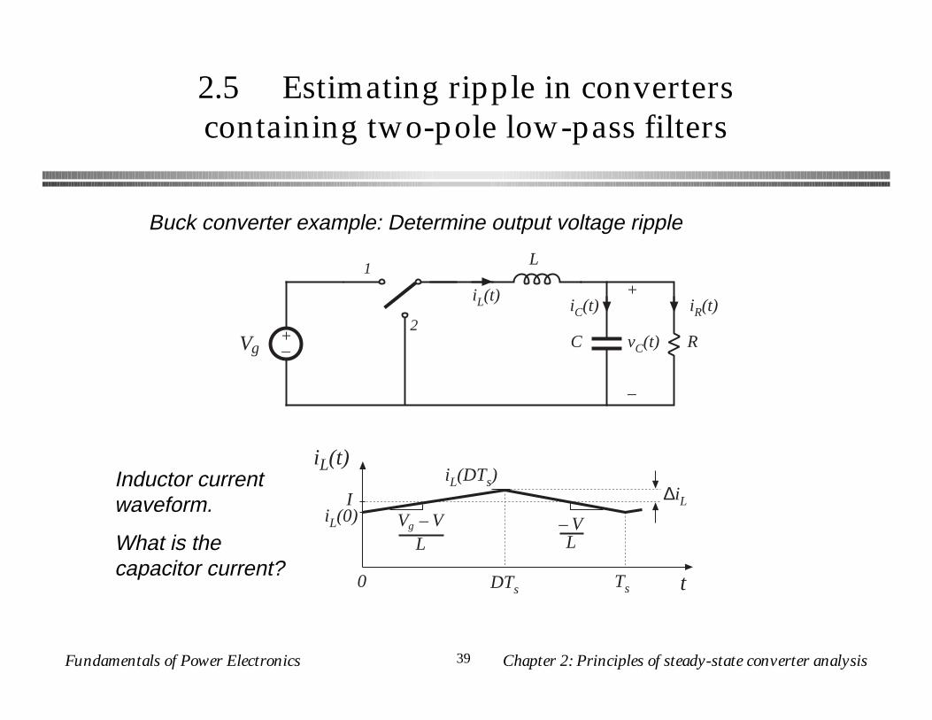
2.5 Estimating ripple in converterscontaining two-pole low-pass filters
+–Vg
L
C R
+
vC(t)
–
1
2iC(t) iR(t)
iL(t)
Buck converter example: Determine output voltage ripple
iL(t)
t0 DTs Ts
IiL(0) Vg – V
L
iL(DTs)∆iL
– VL
Inductor current waveform.
What is the capacitor current?
Fundamentals of Power Electronics Chapter 2: Principles of steady-state converter analysis40
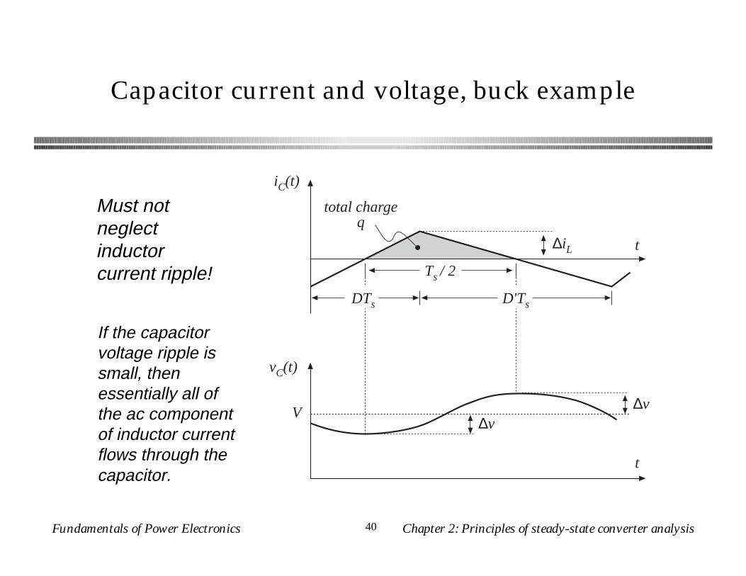
Capacitor current and voltage, buck example
Must not neglect inductor current ripple!
iC(t)
vC(t)
t
t
total chargeq
DTs D'Ts
Ts / 2
V
∆iL
∆v∆v
If the capacitor voltage ripple is small, then essentially all of the ac component of inductor current flows through the capacitor.
Fundamentals of Power Electronics Chapter 2: Principles of steady-state converter analysis41
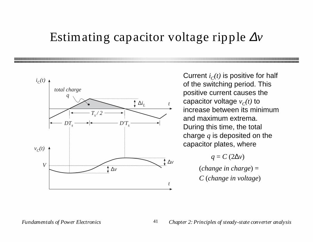
Estimating capacitor voltage ripple ∆v
iC(t)
vC(t)
t
t
total chargeq
DTs D'Ts
Ts / 2
V
∆iL
∆v∆v
q = C (2∆v)
Current iC(t) is positive for half of the switching period. This positive current causes the capacitor voltage vC(t) to increase between its minimum and maximum extrema. During this time, the total charge q is deposited on the capacitor plates, where
(change in charge) =C (change in voltage)
Fundamentals of Power Electronics Chapter 2: Principles of steady-state converter analysis42
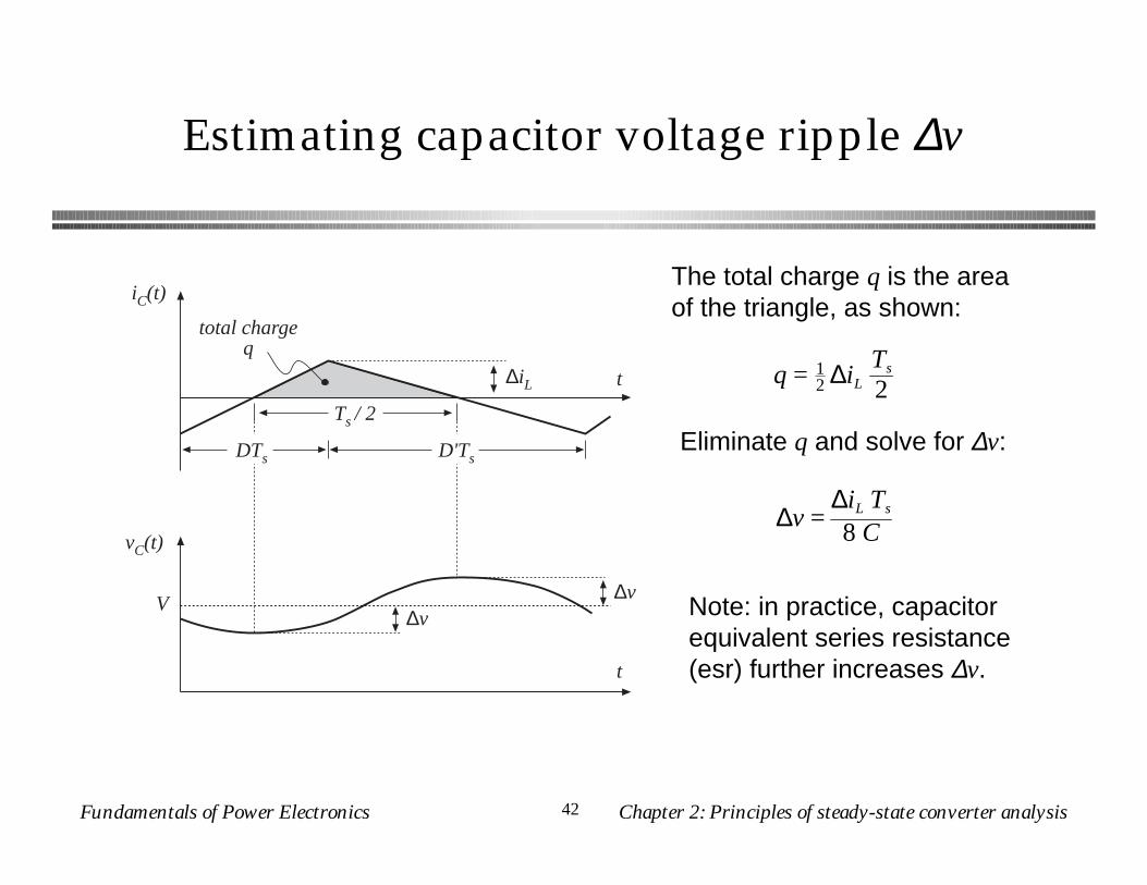
Estimating capacitor voltage ripple ∆v
iC(t)
vC(t)
t
t
total chargeq
DTs D'Ts
Ts / 2
V
∆iL
∆v∆v
The total charge q is the area of the triangle, as shown:
q = 12 ∆iL
Ts
2
Eliminate q and solve for ∆v:
∆v =∆iL Ts
8 C
Note: in practice, capacitor equivalent series resistance (esr) further increases ∆v.
Fundamentals of Power Electronics Chapter 2: Principles of steady-state converter analysis43
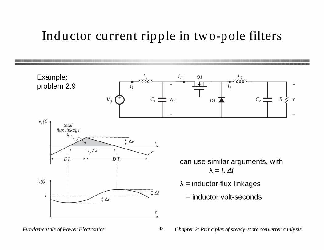
Inductor current ripple in two-pole filters
Example: problem 2.9
D1
Q1
R
+
v
–
+–Vg C2
i1 i2
L2L1
C1
+
vC1
–
iT
vL(t)
iL(t)
t
t
totalflux linkage
λ
DTs D'Ts
Ts / 2
I
∆v
∆i∆i
can use similar arguments, with λ = L ∆i
λ = inductor flux linkages
= inductor volt-seconds
Fundamentals of Power Electronics Chapter 2: Principles of steady-state converter analysis44
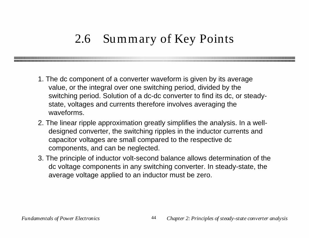
2.6 Summary of Key Points
1. The dc component of a converter waveform is given by its average value, or the integral over one switching period, divided by the switching period. Solution of a dc-dc converter to find its dc, or steady-state, voltages and currents therefore involves averaging the waveforms.
2. The linear ripple approximation greatly simplifies the analysis. In a well-designed converter, the switching ripples in the inductor currents and capacitor voltages are small compared to the respective dc components, and can be neglected.
3. The principle of inductor volt-second balance allows determination of the dc voltage components in any switching converter. In steady-state, the average voltage applied to an inductor must be zero.
Fundamentals of Power Electronics Chapter 2: Principles of steady-state converter analysis45
Summary of Chapter 2
4. The principle of capacitor charge balance allows determination of the dc components of the inductor currents in a switching converter. In steady-state, the average current applied to a capacitor must be zero.
5. By knowledge of the slopes of the inductor current and capacitor voltage waveforms, the ac switching ripple magnitudes may be computed. Inductance and capacitance values can then be chosen to obtain desired ripple magnitudes.
6. In converters containing multiple-pole filters, continuous (nonpulsating) voltages and currents are applied to one or more of the inductors or capacitors. Computation of the ac switching ripple in these elements can be done using capacitor charge and/or inductor flux-linkage arguments, without use of the small-ripple approximation.
7. Converters capable of increasing (boost), decreasing (buck), and inverting the voltage polarity (buck-boost and Cuk) have been described. Converter circuits are explored more fully in a later chapter.