Embed Size (px)
Citation preview
Inductor and Transformer
XMUT303 Analogue Electronics
Topics
• Ideal transformer.
• Equivalent circuit of transformer.
• Impedance matching using transformer.
• Design of a simple line power supply transformer.
• Design of inductor for power converter application.
Ideal Transformer
• We have so far considered the impedance of resistors, capacitors and inductors.
• One other component we are likely to meet in practice is the transformer.
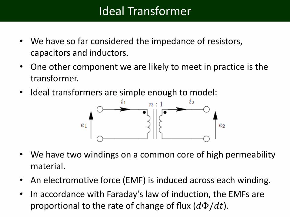
• Ideal transformers are simple enough to model:
• We have two windings on a common core of high permeability material.
• An electromotive force (EMF) is induced across each winding.
• In accordance with Faraday’s law of induction, the EMFs are proportional to the rate of change of flux (𝑑Φ/𝑑𝑡).
Ideal Transformer
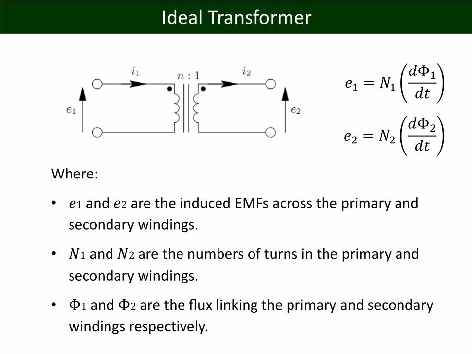
Where:
• 𝑒1 and 𝑒2 are the induced EMFs across the primary and
secondary windings.
• 𝑁1 and 𝑁2 are the numbers of turns in the primary and
secondary windings.
• Φ1 and Φ2 are the flux linking the primary and secondary
windings respectively.
𝑒1 = 𝑁1𝑑Φ1
𝑑𝑡
𝑒2 = 𝑁2𝑑Φ2
𝑑𝑡

Ideal Transformer
• In the ideal transformer, all flux produced by the primary winding also links the secondary, and so Φ1 = Φ2.
• The ratio of primary (𝑒1) to secondary voltage (𝑒2) is therefore the same as the ratio of the number of turns (𝑁1: 𝑁2).
Ideal Transformer
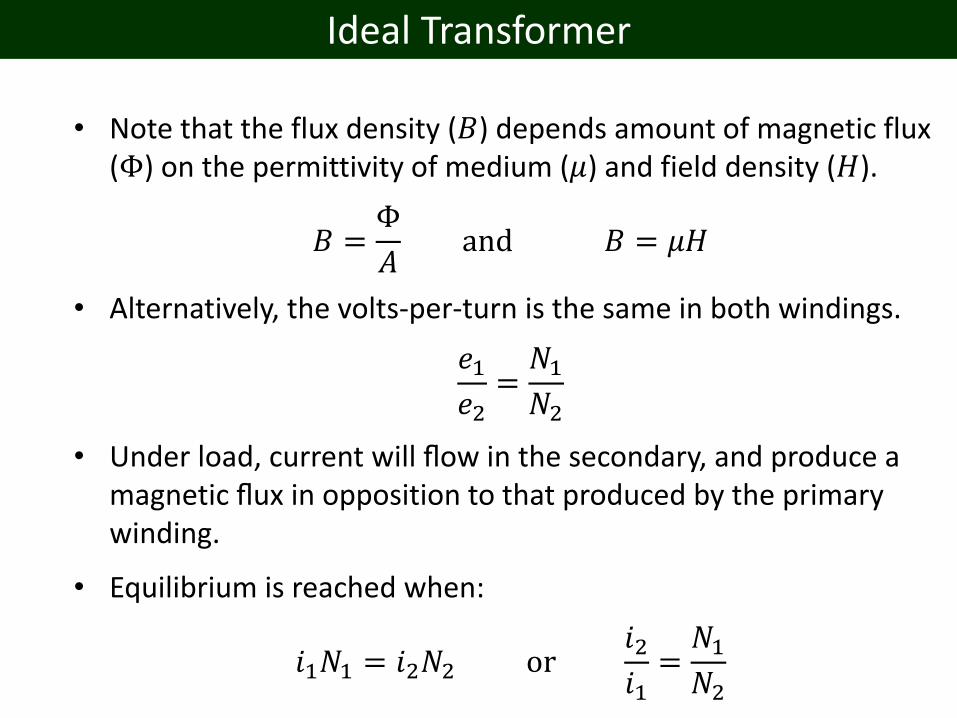
• Note that the flux density (𝐵) depends amount of magnetic flux (Φ) on the permittivity of medium (𝜇) and field density (𝐻).
𝐵 =Φ
𝐴and 𝐵 = 𝜇𝐻
• Alternatively, the volts-per-turn is the same in both windings.
𝑒1𝑒2
=𝑁1𝑁2
• Under load, current will flow in the secondary, and produce a magnetic flux in opposition to that produced by the primary winding.
• Equilibrium is reached when:
𝑖1𝑁1 = 𝑖2𝑁2 or𝑖2𝑖1=𝑁1𝑁2
Ideal Transformer in Circuit
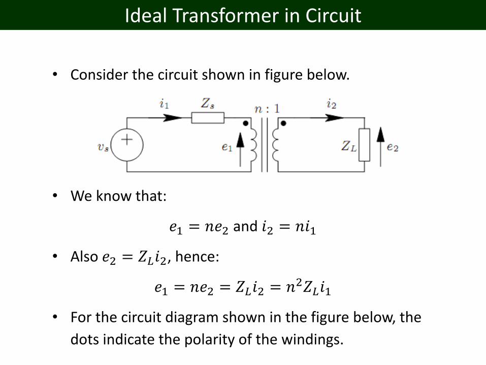
• Consider the circuit shown in figure below.
• We know that:
𝑒1 = 𝑛𝑒2 and 𝑖2 = 𝑛𝑖1
• Also 𝑒2 = 𝑍𝐿𝑖2, hence:
𝑒1 = 𝑛𝑒2 = 𝑍𝐿𝑖2 = 𝑛2𝑍𝐿𝑖1
• For the circuit diagram shown in the figure below, the
dots indicate the polarity of the windings.
Equivalent Circuit (Source Side)
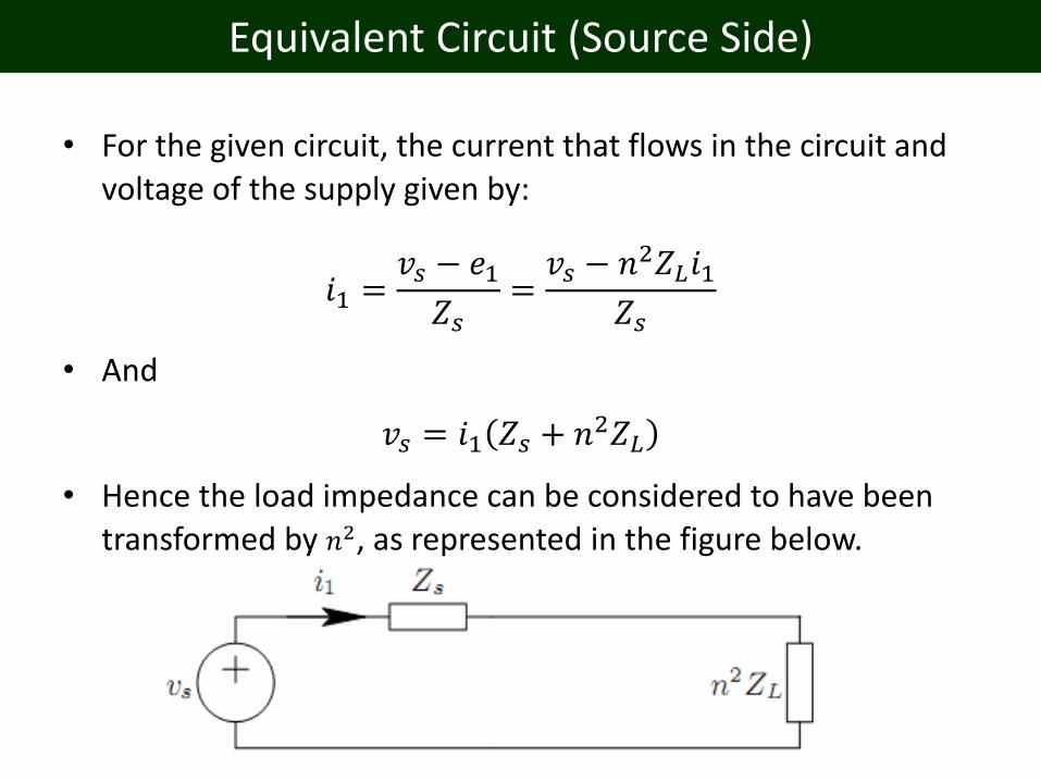
• For the given circuit, the current that flows in the circuit and voltage of the supply given by:
𝑖1 =𝑣𝑠 − 𝑒1𝑍𝑠
=𝑣𝑠 − 𝑛2𝑍𝐿𝑖1
𝑍𝑠
• And
𝑣𝑠 = 𝑖1 𝑍𝑠 + 𝑛2𝑍𝐿
• Hence the load impedance can be considered to have been transformed by 𝑛2, as represented in the figure below.
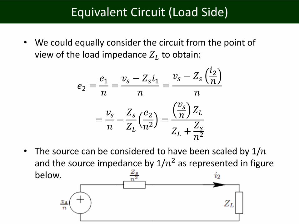
Equivalent Circuit (Load Side)
• We could equally consider the circuit from the point of view of the load impedance 𝑍𝐿 to obtain:
𝑒2 =𝑒1𝑛=𝑣𝑠 − 𝑍𝑠𝑖1
𝑛=𝑣𝑠 − 𝑍𝑠
𝑖2𝑛
𝑛
=𝑣𝑠𝑛−𝑍𝑠𝑍𝐿
𝑒2𝑛2
=
𝑣𝑠𝑛
𝑍𝐿
𝑍𝐿 +𝑍𝑠𝑛2
• The source can be considered to have been scaled by 1/𝑛and the source impedance by 1/𝑛2 as represented in figure below.
Application of Transformer
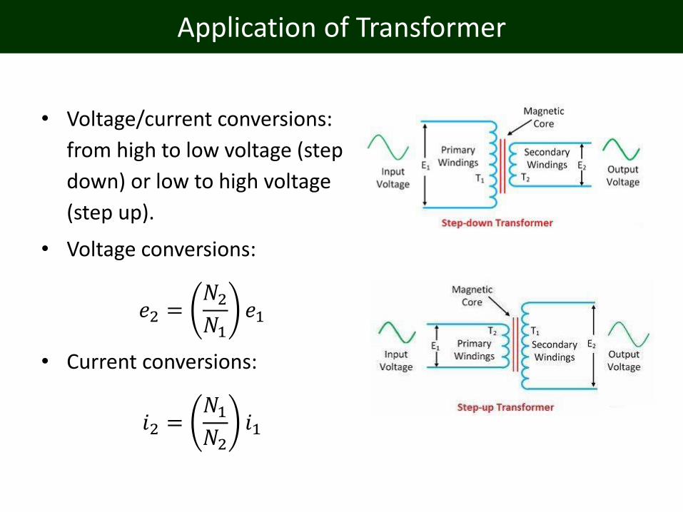
• Voltage/current conversions:
from high to low voltage (step
down) or low to high voltage
(step up).
• Voltage conversions:
𝑒2 =𝑁2𝑁1
𝑒1
• Current conversions:
𝑖2 =𝑁1𝑁2
𝑖1

Application of Transformer
• Other application of a transformer is for impedance matching.
• By carefully choosing and matching the impedance of a load with its source, we can ensure maximum power transfer from the source to the load.
Application of Transformer
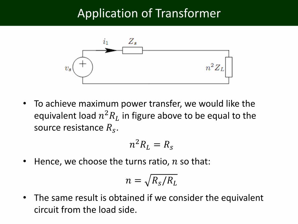
• To achieve maximum power transfer, we would like the equivalent load 𝑛2𝑅𝐿 in figure above to be equal to the source resistance 𝑅𝑠.
𝑛2𝑅𝐿 = 𝑅𝑠
• Hence, we choose the turns ratio, 𝑛 so that:
𝑛 = 𝑅𝑠/𝑅𝐿
• The same result is obtained if we consider the equivalent circuit from the load side.
Transformer Design Process
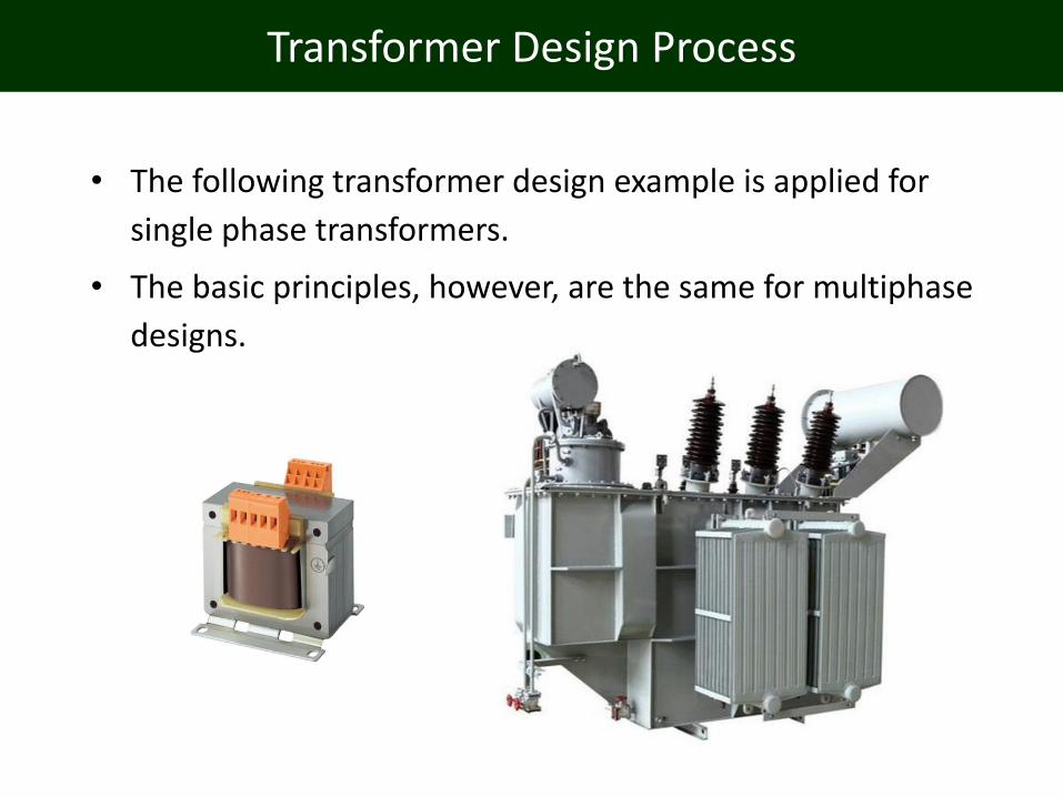
• The following transformer design example is applied for
single phase transformers.
• The basic principles, however, are the same for multiphase
designs.

Transformer Design Process
• The transformer design process normally consists of steps for
determining:
• Transformer rating e.g. rated primary voltage, current and
operating frequency.
• Magnetic design e.g. flux density and inductance of the
transformer.
• Transformation ratio e.g. voltage ratio and turns ratio.
• Power determination and thermal constraints e.g.
maximum body and ambient temperature.

Transformer Design Process
Transformer Rating
For a given transformer design:
• It is for line frequency application (220 V AC, 50 Hz).
• Small power application and losses.
• Use E-shape core laminated magnetic material.
• Windings of primary and secondary coils are with insulated
copper wire.

Transformer Design Process
• The following diagram shows other commonly found examples of transformer laminations.

Transformer Design Process
Magnetic Design
• One of the most important parameters imposing limitations
on the volts per turn for line frequency application is the
maximum flux density in the core of the transformer.
• Typical values of flux density, 𝐵 are 1 to 1.7 Tesla.
• As the frequency of operation increases (i.e. above a few
hundred Hertz), the core losses will be the limiting factor.
• The change in flux is the major source for core losses, and
thus the flux must be limited in accordance with the
manufacturers specification for the given core and
frequency.
• Typical values of magnetic flux, Φ are 0.05 to 0.2 Weber.
Transformer Design Process
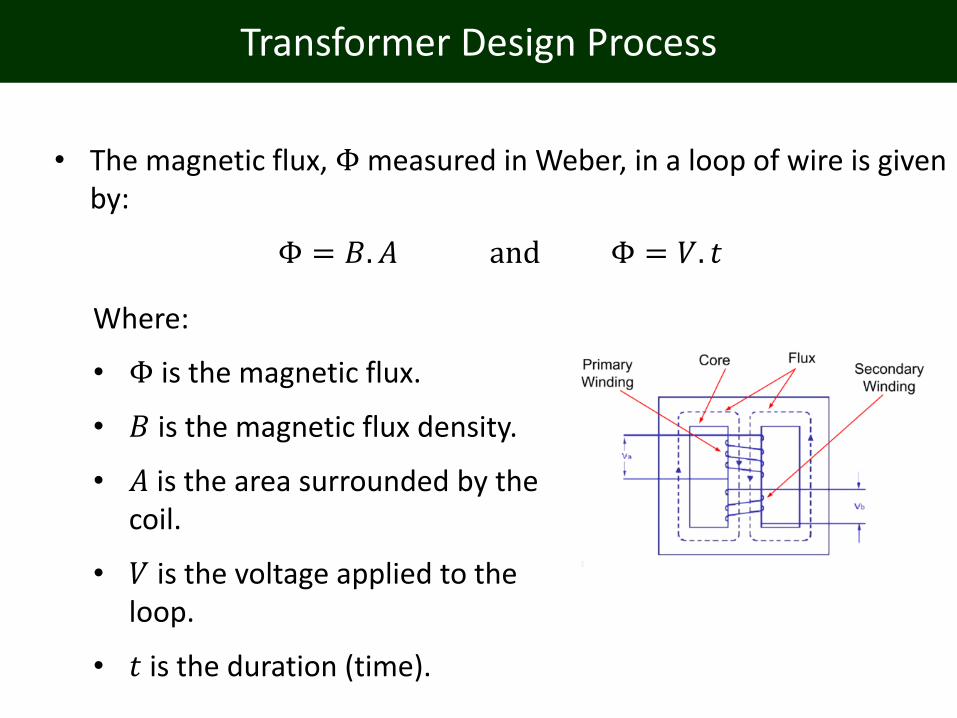
• The magnetic flux, Φ measured in Weber, in a loop of wire is given by:
Φ = 𝐵. 𝐴 and Φ = 𝑉. 𝑡
Where:
• Φ is the magnetic flux.
• 𝐵 is the magnetic flux density.
• 𝐴 is the area surrounded by the coil.
• 𝑉 is the voltage applied to the loop.
• 𝑡 is the duration (time).

Transformer Design Process
Transformation Ratio
• By adding more turns to the coil, the applied voltage will be divided evenly among the turns, hence:
Φ =𝑉. 𝑡
𝑁
Where:
• 𝑉 is the voltage applied to the loop.
• 𝑡 is the duration (time).
• 𝑁 is the number of turns.
Transformer Design Process
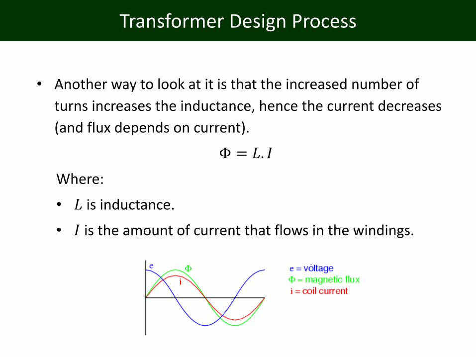
• Another way to look at it is that the increased number of
turns increases the inductance, hence the current decreases
(and flux depends on current).
Φ = 𝐿. 𝐼
Where:
• 𝐿 is inductance.
• 𝐼 is the amount of current that flows in the windings.
Transformer Design Process
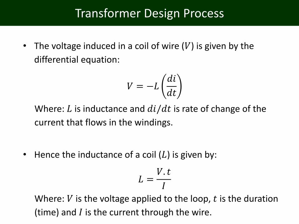
• The voltage induced in a coil of wire (𝑉) is given by the
differential equation:
𝑉 = −𝐿𝑑𝑖
𝑑𝑡
Where: 𝐿 is inductance and 𝑑𝑖/𝑑𝑡 is rate of change of the
current that flows in the windings.
• Hence the inductance of a coil (𝐿) is given by:
𝐿 =𝑉. 𝑡
𝐼
Where: 𝑉 is the voltage applied to the loop, 𝑡 is the duration
(time) and 𝐼 is the current through the wire.

Transformer Design Process
Leakage Inductance
• The leakage inductance is caused by the parts of the magnetic
flux that does not link the primary and secondary windings.
• In most transformers the leakage inductance should be
minimized.
• A unfavorable leakage inductance may cause “over voltages” in
a switching power converter, adding additional requirement to
the snubber circuits.
Transformer Design Process
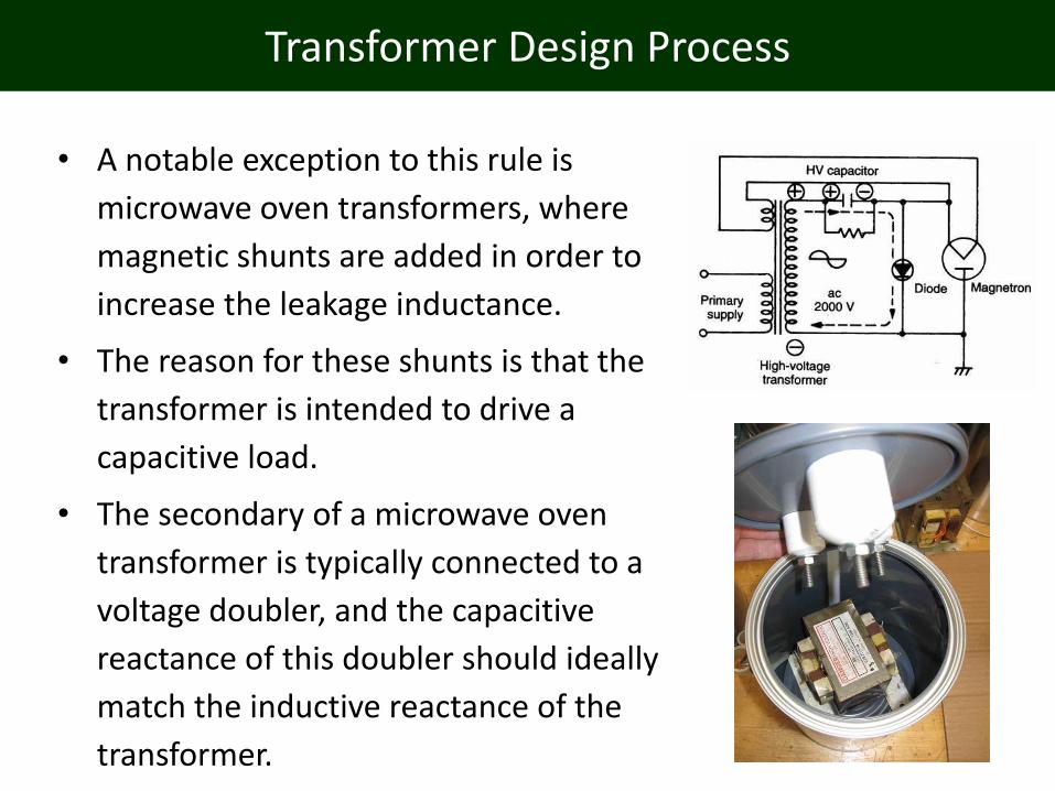
• A notable exception to this rule is
microwave oven transformers, where
magnetic shunts are added in order to
increase the leakage inductance.
• The reason for these shunts is that the
transformer is intended to drive a
capacitive load.
• The secondary of a microwave oven
transformer is typically connected to a
voltage doubler, and the capacitive
reactance of this doubler should ideally
match the inductive reactance of the
transformer.
Transformer Design Process
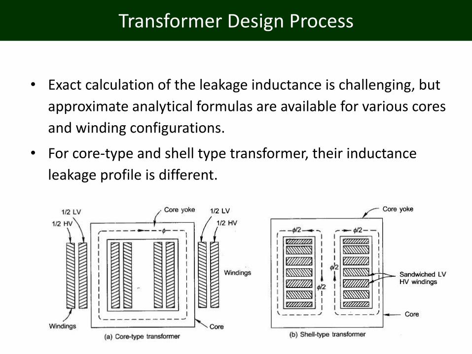
• Exact calculation of the leakage inductance is challenging, but
approximate analytical formulas are available for various cores
and winding configurations.
• For core-type and shell type transformer, their inductance
leakage profile is different.
Transformer Design Process
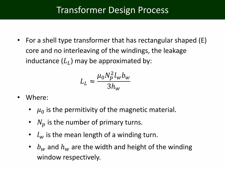
• For a shell type transformer that has rectangular shaped (E)
core and no interleaving of the windings, the leakage
inductance (𝐿𝐿) may be approximated by:
𝐿𝐿 ≈𝜇0𝑁𝑝
2𝑙𝑤𝑏𝑤
3ℎ𝑤
• Where:
• 𝜇0 is the permitivity of the magnetic material.
• 𝑁𝑝 is the number of primary turns.
• 𝑙𝑤 is the mean length of a winding turn.
• 𝑏𝑤 and ℎ𝑤 are the width and height of the winding
window respectively.

Transformer Design Process
• For split (interleaved) winding arrangements,
the leakage inductance (𝐿𝐿) may be
approximated by:
𝐿𝐿 ≈𝜇0𝑁𝑝
2𝑙𝑤
𝑝2ℎ𝑤
𝑏𝑐𝑢3
+ 𝑏𝑖
Where:
• 𝜇0 is the permitivity of the magnetic material,
• 𝑁𝑝 is the number of primary turns.
• 𝑙𝑤 is the mean length of a winding turn.
• ℎ𝑤 is the height of the winding window respectively.
• 𝑝 is the number of interlacing sections.
• 𝑏𝑐𝑢 is the width of the copper in the window of the windings.
• 𝑏𝑖 is the inter winding insulation thickness.
Transformer Design Process
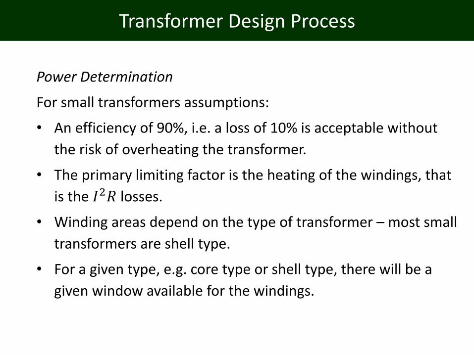
Power Determination
For small transformers assumptions:
• An efficiency of 90%, i.e. a loss of 10% is acceptable without
the risk of overheating the transformer.
• The primary limiting factor is the heating of the windings, that
is the 𝐼2𝑅 losses.
• Winding areas depend on the type of transformer – most small
transformers are shell type.
• For a given type, e.g. core type or shell type, there will be a
given window available for the windings.
Transformer Design Process
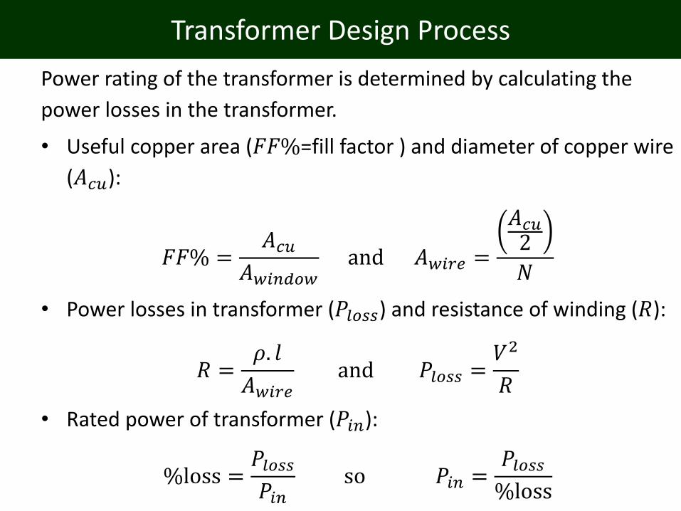
Power rating of the transformer is determined by calculating the
power losses in the transformer.
• Useful copper area (𝐹𝐹%=fill factor ) and diameter of copper wire
(𝐴𝑐𝑢):
𝐹𝐹% =𝐴𝑐𝑢
𝐴𝑤𝑖𝑛𝑑𝑜𝑤and 𝐴𝑤𝑖𝑟𝑒 =
𝐴𝑐𝑢2
𝑁
• Power losses in transformer (𝑃𝑙𝑜𝑠𝑠) and resistance of winding (𝑅):
𝑅 =𝜌. 𝑙
𝐴𝑤𝑖𝑟𝑒and 𝑃𝑙𝑜𝑠𝑠 =
𝑉2
𝑅
• Rated power of transformer (𝑃𝑖𝑛):
%loss =𝑃𝑙𝑜𝑠𝑠𝑃𝑖𝑛
so 𝑃𝑖𝑛 =𝑃𝑙𝑜𝑠𝑠%loss

Transformer Design Example
Transformer design case study:
• Suppose you want to design a power transformer operating at a primary voltage (𝑉𝑝) of 230 V
(RMS), at a frequency (𝑓) of 50 Hz.
• Secondary voltage (𝑉𝑠) is approximately 18 V.
• The core for our example has a cross sectional area, 𝐴 of 45 mm x 30 mm which is 13.5 cm2, and a desired maximum flux density, 𝐵of 1.3 T.

Transformer Design Example
Magnetic Design
• The maximum flux (Φmax) in the core (Φ) is then calculated as:
Φmax = 𝐵. 𝐴 = 1.3 1.35 × 10−3 = 1.76 × 10⁻³ Wb
• The maximum flux change in the shell type transformer however is double, as the core may be magnetized in both directions, i.e. 3.52 mWb.

Transformer Design Example
Transformation Ratio
• The number of turns (𝑁) required to obtain this flux is given by:
𝑁 =𝑉. 𝑡
Φ• The time constant (𝑡) is found from:
𝑡 =1
2𝑓=
1
2 × 50 Hz= 0.01 second
Transformer Design Example
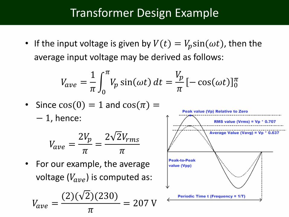
• If the input voltage is given by 𝑉(𝑡) = 𝑉𝑝sin(𝜔𝑡), then the
average input voltage may be derived as follows:
𝑉𝑎𝑣𝑒 =1
𝜋න0
𝜋
𝑉𝑝 sin 𝜔𝑡 𝑑𝑡 =𝑉𝑝
𝜋−cos 𝜔𝑡 0
𝜋
• Since cos(0) = 1 and cos(𝜋) =
− 1, hence:
𝑉𝑎𝑣𝑒 =2𝑉𝑝
𝜋=2 2𝑉𝑟𝑚𝑠
𝜋
• For our example, the average
voltage (𝑉𝑎𝑣𝑒) is computed as:
𝑉𝑎𝑣𝑒 =(2)( 2)(230)
𝜋= 207 V

Transformer Design Example
• The required number of primary turns (𝑁𝑝) is computed as:
𝑁𝑝 =𝑉𝑎𝑣𝑒𝑡
Φ=(207)(0.01)
3.52 mWb= 588 turns
• Hence, expressed in terms of RMS, we have:
𝑉/𝑡𝑢𝑟𝑛 = 230/588 = 0.39 volts (rms) per turn
• Or
𝑁/𝑣𝑜𝑙𝑡 = 588/230 = 2.56 turns per volt (rms)
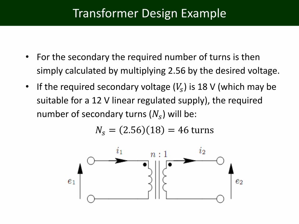
Transformer Design Example
• For the secondary the required number of turns is then
simply calculated by multiplying 2.56 by the desired voltage.
• If the required secondary voltage (𝑉𝑠) is 18 V (which may be
suitable for a 12 V linear regulated supply), the required
number of secondary turns (𝑁𝑠) will be:
𝑁𝑠 = 2.56 18 = 46 turns

Transformer Design Example
Power Determination
• For a given type, e.g. core type or shell type, there will be a given window available for the windings.
• The shell type used in the winding example has a window area (𝐴𝑤𝑖𝑛𝑑𝑜𝑤) of:
𝐴𝑤𝑖𝑛𝑑𝑜𝑤 = 45 mm x 15 mm
= 6.75 × 10⁻²m2
• Additionally the distance around the core (𝐿𝑐𝑜𝑟𝑒) is:
𝐿𝑐𝑜𝑟𝑒 = 45 + 45 + 30 + 30= 150 mm = 0.15 m
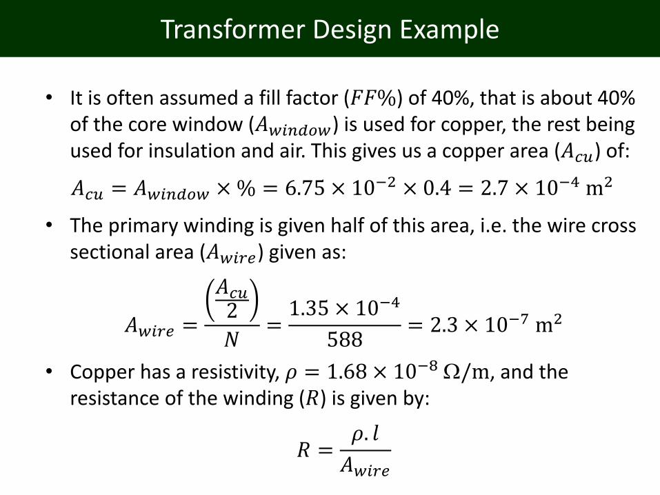
Transformer Design Example
• It is often assumed a fill factor (𝐹𝐹%) of 40%, that is about 40% of the core window (𝐴𝑤𝑖𝑛𝑑𝑜𝑤) is used for copper, the rest being used for insulation and air. This gives us a copper area (𝐴𝑐𝑢) of:
𝐴𝑐𝑢 = 𝐴𝑤𝑖𝑛𝑑𝑜𝑤 ×% = 6.75 × 10−2 × 0.4 = 2.7 × 10⁻⁴ m2
• The primary winding is given half of this area, i.e. the wire cross sectional area (𝐴𝑤𝑖𝑟𝑒) given as:
𝐴𝑤𝑖𝑟𝑒 =
𝐴𝑐𝑢2
𝑁=1.35 × 10⁻⁴
588= 2.3 × 10⁻⁷ m2
• Copper has a resistivity, 𝜌 = 1.68 × 10⁻⁸ /m, and the resistance of the winding (𝑅) is given by:
𝑅 =𝜌. 𝑙
𝐴𝑤𝑖𝑟𝑒

Transformer Design Example
• If the average turns length 200 mm = 0.2 m, the total length (𝑙) is about 0.2 x 588 = 117.6 m. The winding resistance (𝑅) is then given as:
𝑅 =1.68 × 10⁻⁸ 117.6
2.3 × 10−7= 8.59
• As previously stated we will allow a power loss of 10%, i.e. the primary winding will be allowed a loss of 5%.
𝑃𝑙𝑜𝑠𝑠 =𝑉2
𝑅=(230 V × 0.05)2
8.59 Ω= 15.4 W
• The rated input power of the transformer (𝑃𝑖𝑛) is then computed as:
𝑃𝑖𝑛 =𝑃𝑙𝑜𝑠𝑠% 𝑙𝑜𝑠𝑠
=15.4 W
0.1= 154W

A Note About DC Current
• DC current in a transformer is normally not a good thing.
• It will not contribute to the power delivered by the
transformer, but it will contribute to the magnetic flux in the
core. This means that the core will be closer to saturation.
• If the transformer is designed to be at the edge of
saturation without DC current, it will saturate.
• If you intend to have DC current in the transformer, you
should apply the same design constraints as when designing
a inductor intended for DC.
• Typically this means adding an air gap to the core, in order
to reduce the effective permeability.
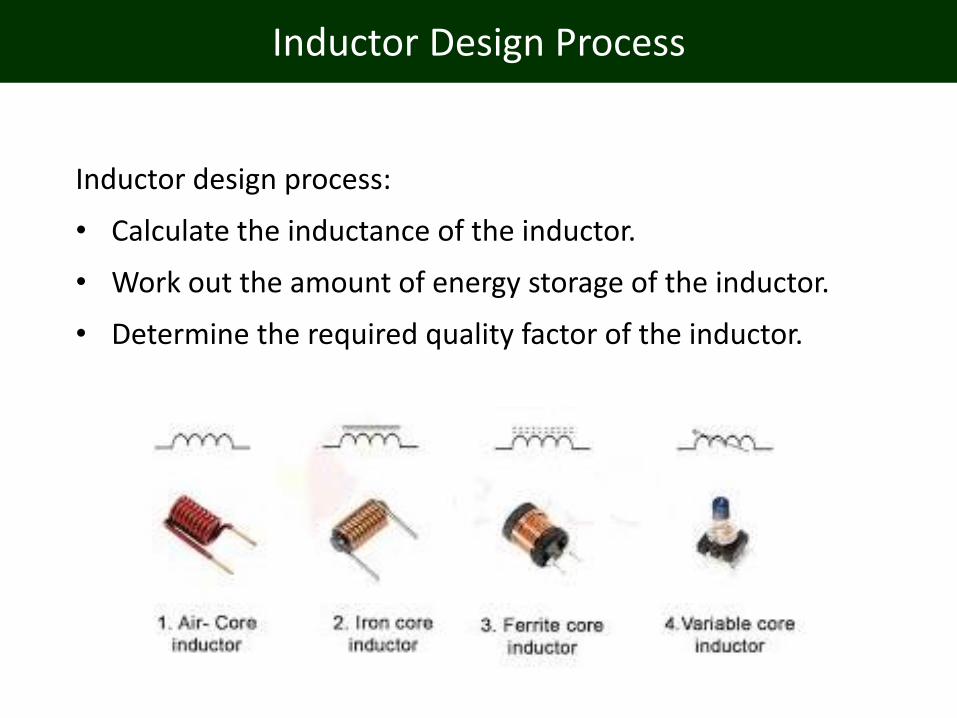
Inductor Design Process
Inductor design process:
• Calculate the inductance of the inductor.
• Work out the amount of energy storage of the inductor.
• Determine the required quality factor of the inductor.
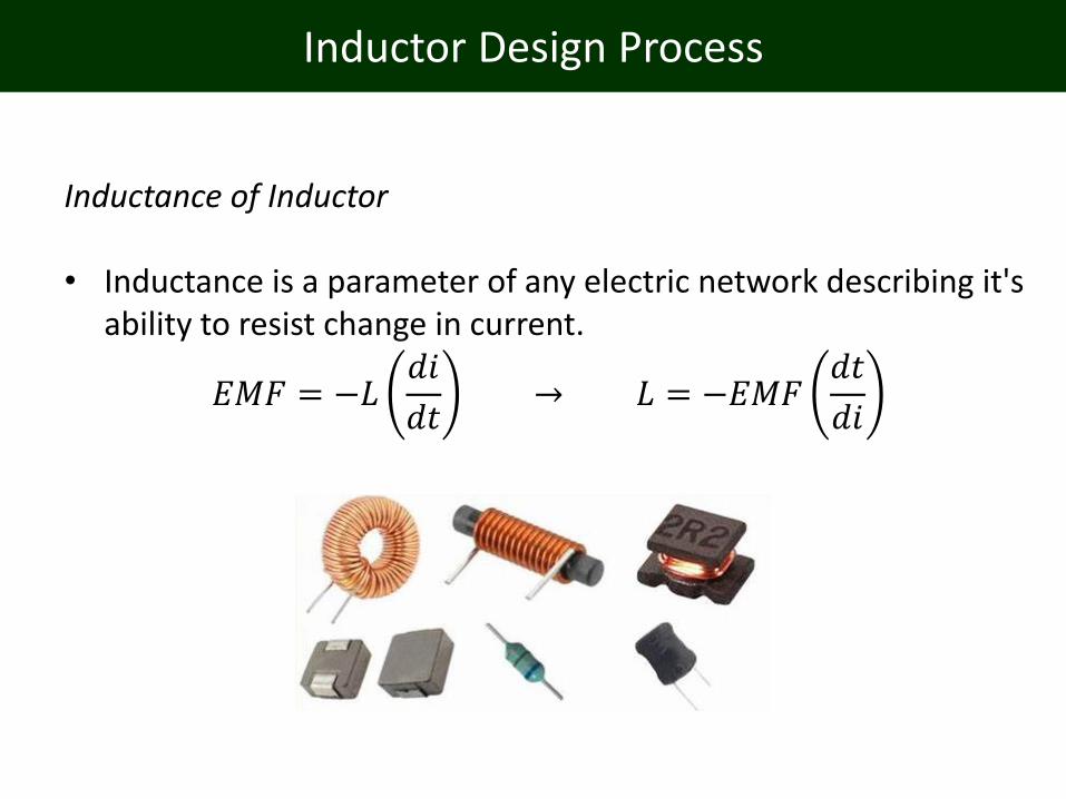
Inductor Design Process
Inductance of Inductor
• Inductance is a parameter of any electric network describing it's ability to resist change in current.
𝐸𝑀𝐹 = −𝐿𝑑𝑖
𝑑𝑡→ 𝐿 = −𝐸𝑀𝐹
𝑑𝑡
𝑑𝑖

Inductor Design Process
Energy Storage
• Energy storage is usually not desired in transformers, it is however often the primary purpose of an inductor.
• It is among other things used in the switching converter circuit. The energy stored in a inductor is given by:
𝐸 =1
2. 𝐿. 𝐼2
Where:
𝐼 is the magnetizing current (i.e. when computing the energy storage in a transformer, it will be less that the total current).
Inductor Design Process
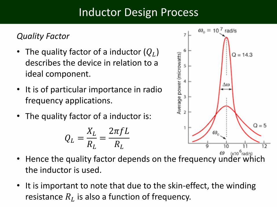
Quality Factor
• The quality factor of a inductor (𝑄𝐿) describes the device in relation to a ideal component.
• It is of particular importance in radio frequency applications.
• The quality factor of a inductor is:
𝑄𝐿 =𝑋𝐿𝑅𝐿
=2𝜋𝑓𝐿
𝑅𝐿
• Hence the quality factor depends on the frequency under which the inductor is used.
• It is important to note that due to the skin-effect, the winding resistance 𝑅𝐿 is also a function of frequency.

Inductor Design Example
• Our inductor core has a cross sectional area, 𝐴 of 3 cm2, and a desired maximum flux density, 𝐵 of 0.05 Tesla at the frequency of operation.
• Suppose we want to design an inductor for a switching converter operating frequency, 𝑓at 100 kHz, with a duty cycle, 𝑑 of 30%.
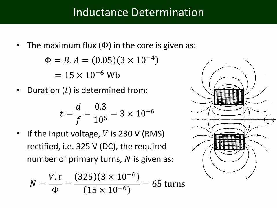
Inductance Determination
• The maximum flux (Φ) in the core is given as:
Φ = 𝐵. 𝐴 = 0.05 3 × 10−4
= 15 × 10−6 Wb
• Duration (𝑡) is determined from:
𝑡 =𝑑
𝑓=0.3
105= 3 × 10⁻⁶
• If the input voltage, 𝑉 is 230 V (RMS)
rectified, i.e. 325 V (DC), the required
number of primary turns, 𝑁 is given as:
𝑁 =𝑉. 𝑡
Φ=
325 3 × 10⁻⁶
15 × 10−6= 65 turns
Inductance Determination
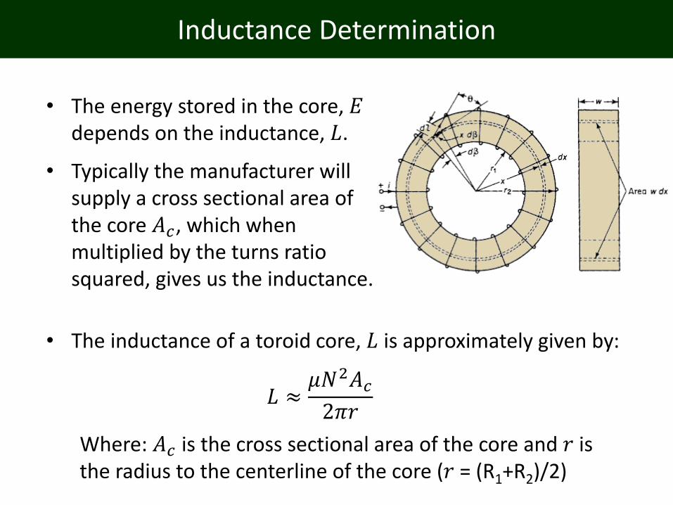
• The inductance of a toroid core, 𝐿 is approximately given by:
𝐿 ≈𝜇𝑁2𝐴𝑐2𝜋𝑟
Where: 𝐴𝑐 is the cross sectional area of the core and 𝑟 is the radius to the centerline of the core (𝑟 = (R1+R2)/2)
• The energy stored in the core, 𝐸depends on the inductance, 𝐿.
• Typically the manufacturer will supply a cross sectional area of the core 𝐴𝑐, which when multiplied by the turns ratio squared, gives us the inductance.
Inductance Determination
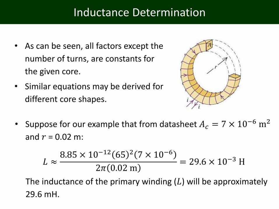
• Suppose for our example that from datasheet 𝐴𝑐 = 7 × 10⁻⁶ m2
and 𝑟 = 0.02 m:
𝐿 ≈8.85 × 10⁻¹² 65 2 7 × 10⁻⁶
2𝜋 0.02 m= 29.6 × 10⁻³ H
The inductance of the primary winding (𝐿) will be approximately
29.6 mH.
• As can be seen, all factors except the
number of turns, are constants for
the given core.
• Similar equations may be derived for
different core shapes.
Energy Storage
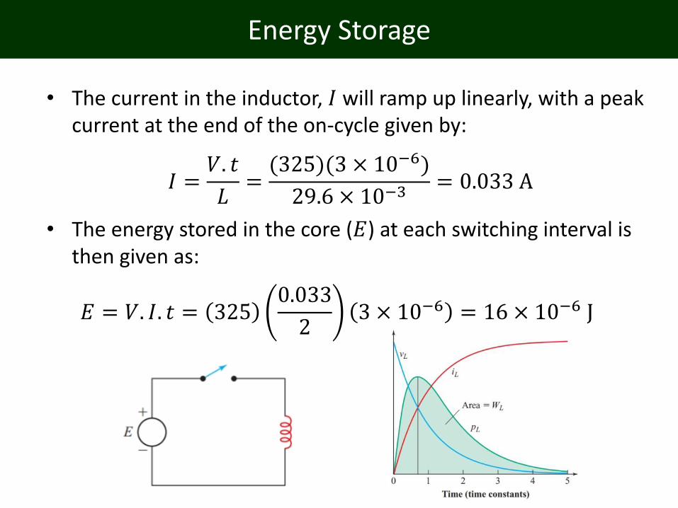
• The current in the inductor, 𝐼 will ramp up linearly, with a peak current at the end of the on-cycle given by:
𝐼 =𝑉. 𝑡
𝐿=(325)(3 × 10⁻⁶)
29.6 × 10−3= 0.033 A
• The energy stored in the core (𝐸) at each switching interval is then given as:
𝐸 = 𝑉. 𝐼. 𝑡 = 3250.033
23 × 10−6 = 16 × 10−6 J
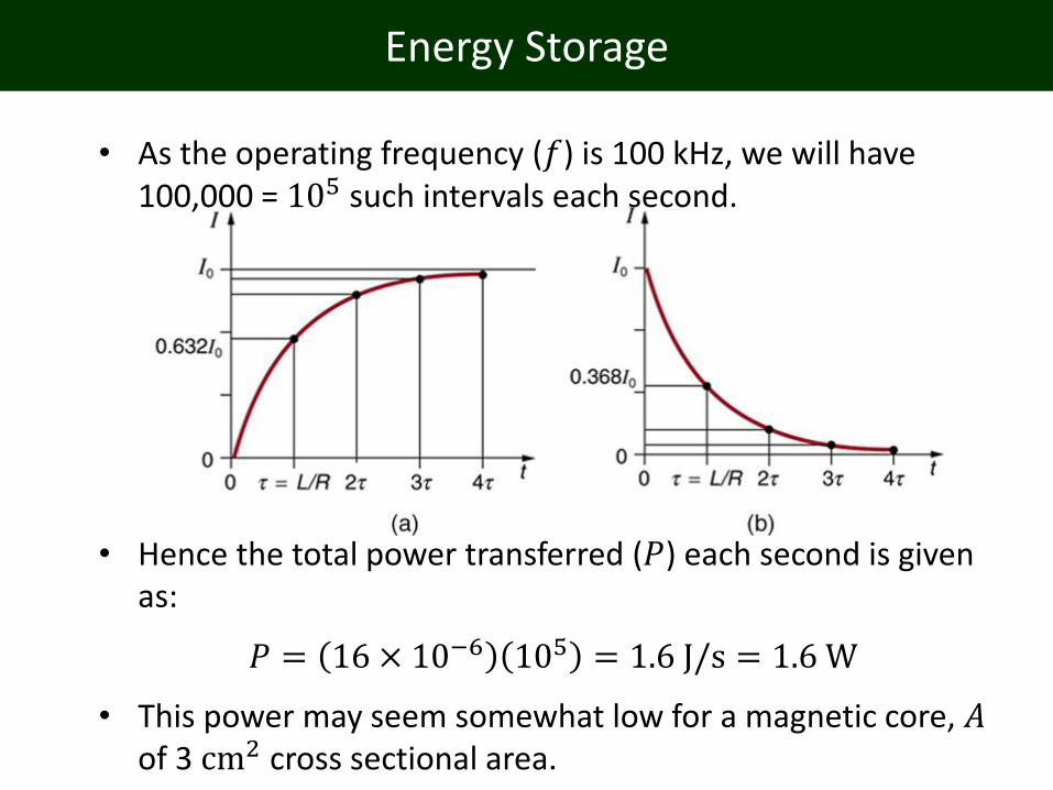
Energy Storage
• As the operating frequency (𝑓) is 100 kHz, we will have 100,000 = 105 such intervals each second.
• Hence the total power transferred (𝑃) each second is given as:
𝑃 = 16 × 10−6 105 = 1.6 J/s = 1.6 W
• This power may seem somewhat low for a magnetic core, 𝐴of 3 cm2 cross sectional area.

Quality Factor Determination
• Remember that the power depends on the current squared.
𝑃 = 𝐼2𝑅
• By introducing an air gap in a magnetic core (𝐼𝑔), the effective
permeability (𝜇) will decrease, and hence the 𝐴𝐿 value will also decrease.
• The best way to increase the power capability is to reduce the inductance, and hence increase the current in the core.

Toroids
• Ferrite has the highest permeability (𝜇), but it is not suitable for high frequencies. Additionally, as we have seen, high permeability is not always an advantage.
• Toroidal cores can be divided into two main categories, depending on the material from which they are made.
• There are two toroid types: ferrite and iron powder cores.

Toroids
• Where: 𝑁 is the number of winding turns, and 𝐴 is the cross sectional area of the core.
• A useful website with specifications for various toroidal cores is located at:
http://toroids.info/
• As previously mentioned the flux density must be limited to avoid saturation of the core.
• For ferrite toroidal cores this imposes the constraint:
𝐵 =𝑉
2𝑓𝑁𝐴≤ 0.3