Embed Size (px)
Citation preview

CHAPTER 2 APPENDICES
Table of Contents
APPENDIX 2-A STANDARDS AND SPECIFICATIONS FOR STORMWATER POLLUTION PREVENTION PLAN BEST MANAGEMENT PRACTICES 2.1 Source Control BMPs 2A-1
BMP C101: Preserving Natural Vegetation 2A-1 BMP C102: Buffer Zones 2A-3 BMP C103: High Visibility Plastic or Metal Fence 2A-4 BMP C104: Stake and Wire Fence 2A-5 BMP C105: Stabilized Construction Entrance 2A-6 BMP C106: Wheel Wash 2A-7 BMP C107: Construction Road/Parking Area Stabilization 2A-9 BMP C120: Temporary and Permanent Seeding 2A-10 BMP C121: Mulching 2A-15 BMP C122: Nets and Blankets 2A-16 BMP C123: Plastic-Covering 2A-20 BMP C124: Sodding 2A-21 BMP C125: Topsoil 2A-22 BMP C126: Polyacrylamide for Soil Erosion Protection 2A-24 BMP C130: Surface-Roughening 2A-27 BMP C131: Gradient Terraces 2A-29 BMP C140: Dust Control 2A-30 BMP C150: Materials On Hand 2A-31 BMP C151: Concrete-Handling 2A-32 BMP C152: Sawcutting and Surfacing Pollution Prevention 2A-33 BMP C153: Material Deliver, Storage and Containment 2A-34 BMP C160: Certified Erosion and Sediment Control Lead 2A-35 BMP C162: Scheduling 2A-36 BMP C180: Small Project Construction Stormwater Pollution Prevention 2A-37
2.2 Runoff Conveyance and Treatment BMPs 2A-38
BMP C200: Interceptor Dike and Swale 2A-38 BMP C201: Grass-Lined Channels 2A-39 BMP C202: Channel Lining 2A-42 BMP C203: Water Bars 2A-43 BMP C204: Pipe Slope Drains 2A-44 BMP C205: Subsurface Drains 2A-46 BMP C206: Level Spreader 2A-48 BMP C207: Check Dams 2A-50 BMP C208: Triangular Silt Dike (Geotextile-Encased Check Dam) 2A-53
2-i

BMP C209: Outlet Protection 2A-54 BMP C220: Storm Drain Inlet Protection 2A-55 BMP C231: Brush Barrier 2A-60 BMP C232: Gravel Filter Berm 2A-61 BMP C233: Silt Fence 2A-62 BMP C234: Vegetated Strip 2A-66 BMP C235: Straw Wattles 2A-67 BMP C240: Sediment Trap 2A-69 BMP C241: Temporary Sediment Pond 2A-71 BMP C250: Construction Stormwater Chemical Treatment 2A-77 BMP C251: Construction Stormwater Filtration 2A-81
APPENDIX 2-B BACKGROUND INFORMATION ON CHEMICAL TREATMENT 2B-1 APPENDIX 2-C DETERMINING CONSTRUCTION SITE SEDIMENT DAMAGE POTENTIAL 2C-1 Construction Site Sediment Transport Potential Worksheet 2C-4 TABLES Table 2.1 Temporary Erosion Control Seed Mix 2A-13 Table 2.2 Landscaping Seed Mix 2A-13 Table 2.3 Low-Growing Turf Seed Mix 2A-13 Table 2.4 Bioswale Seed Mix 2A-13 Table 2.5 Wet Area Seed Mix 2A-14 Table 2.6 Meadow Seed Mix 2A-14 Table 2.7 Mulch Standards and Guidelines 2A-16 Table 2.8 PAM and Water Application Rates 2A-25 Table 2.9 Storm Drain Inlet Protection 2A-55 Table 2.10 Geotextile Standards 2A-63 Table 2.11 Vegetated Strips 2A-67 FIGURES 2.1 Stake and Wire Fence 2A-5 2.2 Stabilized Construction Entrance 15’ min 2A-7 2.3 Wheel Wash 2A-8 2.4 Channel Installation 2A-19 2.5 Slope Installation 2A-20 2.6 Surface Roughening by Tracking and Contour Furrows 2A-28 2.7 Gradient Terraces 2A-30 2.8 Typical Grass-Lined Channels 2A-41 2.9 Temporary Channel Liners 2A-42 2.10 Pipe Slope Drain 2A-46 2.11 Cross Section of Level Spreader 2A-49
2-ii

2.12 Detail of Level Spreader 2A-49 2.13 – Check Dams 2A-52 2.14 Block and Gravel Filter 2A-57 2.15 Block and Gravel Curb Inlet Protection 2A-59 2.16 Curb and Gutter Barrier 2A-60 2.18 Brush Barrier 2A-61 2.19 Silt Fence 2A-62 2.20 Silt Fence Installation by Slicing Method 2A-66 2.21 Straw Wattles 2A-69 2.22 Cross Section of Sediment Trap 2A-71 2.23 Sediment Trap Outlet 2A-71 2.24 Sediment Pond Plan View 2A-73 2.25 Sediment Pond Cross Section 2A-74 2.26 Sediment Pond Riser Detail 2A-74 2.27 Riser Inflow Curves 2A-75
2-iii

APPENDIX 2A - STANDARDS AND SPECIFICATIONS FOR STORMWATER POLLUTION PREVENTION PLAN BEST MANAGEMENT PRACTICES Best Management Practices (BMPs) are defined as schedules of activities, prohibitions of practices, maintenance procedures, and structural and/or managerial practices, that when used singly or in combination, prevent or reduce the release of pollutants to waters of Washington State. This Appendix contains standards and specifications for temporary BMPs to be used as applicable during the construction phase of a project. Section 2.1 contains the standards and specifications for Source Control BMPs. Section 2.2 contains the standards and specifications for Runoff Conveyance and Treatment BMPs. The standards for each individual BMP are divided into four sections: A. Purpose B. Conditions of Use C. Design and Installation Specifications D. Maintenance Standards Note that the “Conditions of Use” always refers to site conditions. As site conditions change, BMPs must be changed to remain in compliance. Information on streambank stabilization is available in the Integrated Streambank Protection Guidelines, Washington State Department of Fish and Wildlife, 2000. 2.1 Source Control BMPs
BMP C101: Preserving Natural Vegetation A. Purpose
The purpose of preserving natural vegetation is to reduce erosion wherever practicable. Limiting site disturbance is the single most effective method for reducing erosion. For example, conifers can hold up to about 50 percent of all rain that falls during a storm. Up to 20-30 percent of this rain may never reach the ground but is taken up by the tree or evaporates. Another benefit is that the rain held in the tree can be released slowly to the ground after the storm.
B. Conditions of Use Natural vegetation should be preserved on steep slopes, near perennial and intermittent watercourses or swales, and on building sites in wooded areas.
C. Design and Installation Specifications Natural vegetation can be preserved in natural clumps or as individual trees, shrubs and vines. The preservation of individual plants is more difficult because heavy equipment is generally used to remove unwanted vegetation. Any plant removal or retention should be coordinated with the final approved
2A-1

landscaping plan and buffer requirements. The points to remember when attempting to save individual plants are: 1. Is the plant worth saving? Consider the location, species, size, age, vigor,
and the work involved. 2. Fence or clearly mark areas around trees that are to be saved. It is
preferable to keep ground disturbance away from the trees at least as far out as the dripline.
3. Plants need protection from three kinds of injuries: a. Construction Equipment - This injury can be above or below the
ground level. Damage results from scarring, cutting of roots, and compaction of the soil. Placing a fenced buffer zone around plants to be saved prior to construction can prevent construction equipment injuries.
b. Grade Changes - Changing the natural ground level will alter grades, which affects the plant's ability to obtain the necessary air, water, and minerals. Minor fills usually do not cause problems although sensitivity between species does vary and should be checked. Trees can tolerate fill of 6 inches or less. For shrubs and other plants, the fill should be less. When there are major changes in grade, it may become necessary to supply air to the roots of plants. This can be done by placing a layer of gravel and a tile system over the roots before the fill is made. A tile system protects a tree from a raised grade. The tile system should be laid out on the original grade leading from a dry well around the tree trunk. The system should then be covered with small stones to allow air to circulate over the root area. Lowering the natural ground level can seriously damage trees and shrubs. The highest percentage of the plant roots are in the upper 12 inches of the soil and cuts of only 2-3 inches can cause serious injury. To protect the roots it may be necessary to terrace the immediate area around the plants to be saved. If roots are exposed, construction of retaining walls may be needed to keep the soil in place. Plants can also be preserved by leaving them on an undisturbed, gently sloping mound. To increase the chances for survival, it is best to limit grade changes and other soil disturbances to areas outside the dripline of the plant.
c. Excavations - Protect trees and other plants when excavating for drainfields, power, water, and sewer lines. Where possible, the trenches should be routed around trees and large shrubs. When this is not possible, it is best to tunnel under them. This can be done with hand tools or with power augers. If it is not possible to route the trench around plants to be saved, then the following should be observed: 1) Cut as few roots as possible. When you have to cut, cut clean. 2) Paint cut root ends with a wood dressing like asphalt base paint. 3) Backfill the trench as soon as possible. 4) Tunnel beneath root systems as close to the center of the main
trunk to preserve most of the important feeder roots. d. Some problems that can be encountered with a few specific trees are:
2A-2

1) Maple, Dogwood, Red alder, Western hemlock, Western red cedar, and Douglas fir do not readily adjust to changes in environment and special care should be taken to protect these trees.
2) The windthrow hazard of Pacific silver fir and madrona is high, while that of Western hemlock is moderate. The danger of windthrow increases where dense stands have been thinned. Other species (unless they are on shallow, wet soils less than 20 inches deep) have a low windthrow hazard.
3) Cottonwoods, maples, and willows have water-seeking roots. These can cause trouble in sewer lines and infiltration fields. On the other hand, they thrive in high moisture conditions that other trees would not.
4) Thinning operations in pure or mixed stands of Grand fir, Pacific silver fir, Noble fir, Sitka spruce, Western red cedar, Western hemlock, Pacific dogwood, and Red alder can cause serious disease problems.
5) Disease can become established through damaged limbs, trunks, roots, and freshly cut stumps. Diseased and weakened trees are also susceptible to insect attack.
D. Maintenance Standards
Inspect flagged and/or fenced areas regularly to make sure flagging or fencing has not been removed or damaged. If the flagging or fencing has been damaged or visibility reduced, it shall be repaired or replaced immediately and visibility restored. 1. If tree roots have been exposed or injured, “prune” cleanly with an
appropriate pruning saw or loppers directly above the damaged roots and recover with native soils. Treatment of sap flowing trees (fir, hemlock, pine, soft maples) is not advised as sap forms a natural healing barrier.
BMP C102: Buffer Zones A. Purpose
An undisturbed area or strip of natural vegetation or an established suitable planting that will provide a living filter to reduce soil erosion and runoff velocities.
B. Conditions of Use Natural buffer zones are used along streams, wetlands and other bodies of water that need protection from erosion and sedimentation. Vegetative buffer zones can be used to protect natural swales and can be incorporated into the natural landscaping of an area.
C. Design and Installation Specifications 1. Preserving natural vegetation or plantings in clumps, blocks, or strips
is generally the easiest and most successful method. 2. Leave all unstable steep slopes in natural vegetation. 3. Mark clearing limits and keep all equipment and construction debris
out of the natural areas. Steel construction fencing is the most effective
2A-3

method in protecting sensitive areas and buffers. Alternatively, wire-backed silt fence on steel posts is marginally effective. Flagging alone is typically not effective.
4. Keep all excavations outside the dripline of trees and shrubs. 5. Do not push debris or extra soil into the buffer zone area because it
will cause damage from burying and smothering. 6. Vegetative buffer zones for streams, lakes or other waterways shall be
in compliance with applicable critical areas, land use and other requirements.
D. Maintenance Standards Inspect the area frequently to make sure flagging remains in place and the area remains undisturbed.
BMP C103: High Visibility Plastic or Metal Fence A. Purpose
Fencing is intended to: (1) restrict clearing to approved limits; (2) prevent disturbance of sensitive areas, their buffers, and other areas required to be left undisturbed; (3) limit construction traffic to designated construction entrances or roads; and, (4) protect areas where marking with survey tape may not provide adequate protection.
B. Conditions of Use To establish clearing limits, plastic or metal fence may be used:
1. At the boundary of sensitive areas, their buffers, and other areas required to be left uncleared.
2. As necessary to control vehicle access to and on the site. C. Design and Installation Specifications
1. High visibility plastic fence shall be composed of a high-density polyethylene material and shall be at least four feet in height. Posts for the fencing shall be steel or wood and placed every 6 feet on center (maximum) or as needed to ensure rigidity. The fencing shall be fastened to the post every six inches with a polyethylene tie. On long continuous lengths of fencing, a tension wire or rope shall be used as a top stringer to prevent sagging between posts. The fence color shall be high visibility orange. The fence tensile strength shall be 360 lbs./ft. using the ASTM D4595 testing method.
2. Metal fences shall be designed and installed according to the manufacturer's specifications.
3. Metal fences shall be at least 3 feet high and must be highly visible. 4. Fences shall not be wired or stapled to trees.
D. Maintenance Standards If the fence has been damaged or visibility reduced, it shall be repaired or replaced immediately and visibility restored.
2A-4

2BMP C104: Stake and Wire Fence A. Purpose
Fencing is intended to: (1) restrict clearing to approved limits; (2) prevent disturbance of sensitive areas, their buffers, and other areas required to be left undisturbed; (3) limit construction traffic to designated construction entrances or roads; and, (4) protect any areas where marking with survey tape may not provide adequate protection.
B. Conditions of Use To establish clearing limits, stake or wire fence may be used: 1. At the boundary of sensitive areas, their buffers, and other areas required
to be left uncleared. 2. As necessary, to control vehicle access to and on the site.
C. Design and Installation Specifications 1. See Figure 2.1 for details. 2. More substantial fencing shall be used if the fence does not prevent
encroachment into those areas that are not to be disturbed. D. Maintenance Standards
If the fence has been damaged or visibility reduced, it shall be repaired or replaced immediately and visibility restored.
Figure 2.1 – Stake and Wire Fence
Survey Flagging Baling Wire Do Not Nail or Staple
Wire to Trees
MetalFence Po
st
2A-5

BMP C105: Stabilized Construction Entrance A. Purpose
Construction entrances are stabilized to reduce the amount of sediment transported onto paved roads by vehicles or equipment by constructing a stabilized pad of quarry spalls at entrances to construction sites.
B. Conditions of Use Construction entrances shall be stabilized wherever traffic will be leaving a construction site and traveling on paved roads or other paved areas within 1,000 feet of the site.
C. Design and Installation Specifications 1. See Figure 4.2 for details. Note: the 100’ minimum length of the entrance may be
reduced to the maximum practicable size when the size or configuration of the site does not allow the full length (100’).
2. A separation geotextile shall be placed under the spalls to prevent fine sediment from pumping up into the rock pad. The geotextile shall meet the following standards: a. Grab Tensile Strength (ASTM D4751) 200 psi min. b. Grab Tensile Elongation (ASTM D4632) 30% max. c. Mullen Burst Strength (ASTM D3786-80a) 400 psi min. d. AOS (ASTM D4751) 20-45 (U.S. standard sieve size)
3. Consider early installation of the first lift of asphalt in areas that will be paved; this can be used as a stabilized entrance. Also consider the installation of excess concrete as a stabilized entrance. During large concrete pours, excess concrete is often available for this purpose.
4. Fencing (see BMPs C103 and C104) shall be installed as necessary to restrict traffic to the construction entrance.
5. Whenever possible, the entrance shall be constructed on a firm, compacted subgrade. This can substantially increase the effectiveness of the pad and reduce the need for maintenance.
D. Maintenance Standards 1. Quarry spalls shall be added if the pad is no longer in accordance with the
specifications. 2. If the entrance is not preventing sediment from being tracked onto pavement, then
alternative measures to keep the streets free of sediment shall be used. This may include street sweeping, an increase in the dimensions of the entrance, or the installation of a wheel wash.
3. Any sediment that is tracked onto pavement shall be removed by shoveling or street sweeping. The sediment collected by sweeping shall be removed or stabilized on site. The pavement shall not be cleaned by washing down the street, except when sweeping is ineffective and there is a threat to public safety. If it is necessary to wash the streets, the construction of a small sump shall be considered. The sediment would then be washed into the sump where it can be controlled.
4. Any quarry spalls that are loosened from the pad, which end up on the roadway shall be removed immediately.
5. If vehicles are entering or exiting the site at points other than the construction entrance(s), fencing (see BMPs C103 and C104) shall be installed to control traffic.
2A-6

6. Upon project completion and site stabilization, all construction accesses intended as permanent access for maintenance shall be permanently stabilized.
Figure 2.2 – Stabilized Construction Entrance 15’ min.
BMP C106: Wheel Wash A. Purpose Wheel washes reduce the amount of sediment transported onto paved roads by motor
vehicles. B. Conditions of Use
1. Wheel washing is used when a stabilized construction entrance (see BMP C105) is not preventing sediment from being tracked onto pavement.
2. Wheel washing is generally an effective BMP when installed with careful attention to topography. For example, a wheel wash can be detrimental if installed at the top of a slope abutting a right-of-way where the water from the dripping truck can run unimpeded into the street.
3. Pressure washing combined with an adequately sized and surfaced pad with direct drainage to a large 10-foot x 10-foot sump can be very effective.
C. Design and Installation Specifications Suggested details are shown in Figure 2.3. A minimum of 6 inches of asphalt treated base (ATB) over crushed base material or 8 inches over a good subgrade is recommended to pave the wheel wash. Use a low clearance truck to test the wheel wash before paving. Either a belly dump or lowboy will work well to test clearance. Keep the water level from 12 to 14 inches deep to avoid damage to truck hubs and filling the truck tongues with water. Midpoint spray nozzles are only needed in extremely muddy conditions. Wheel wash systems should be designed with a small grade change, 6 to 12 inches for a 10-foot-wide pond, to allow sediment to flow to the low side of pond to help prevent re-suspension of sediment. A drainpipe with a 2- to 3-foot riser should be installed on the low side of the pond to allow for easy cleaning and refilling. Polymers may be used to promote coagulation and flocculation in a closed-loop system. Polyacrylamide (PAM) added to the wheel wash water at a rate of 0.25 - 0.5 pounds per 1,000 gallons of water increases effectiveness and reduces
2A-7

cleanup time. If PAM is already being used for dust or erosion control and is being applied by a water truck, the same truck can be used to change the wash water. See BMP C126 for PAM limitations and conditions of use.
C. Maintenance Standards The wheel wash should start out the day with fresh water. The wash water should be changed a minimum of once per day. On large earthwork jobs where more than 10-20 trucks per hour are expected, the wash water will need to be changed more often. Wheel wash or tire bath wastewater shall be discharged to a separate onsite treatment system, such as closed-loop recirculation or land application, or to the sanitary sewer with proper local sewer district approval.
Water levelElevation View
1:1 Slope
Wheel Wash Plan
1:1Slope
5:1Slope
5:1Slope
2%Slope
2%Slope
2" Schedule 401 ½" schedule 40 for sprayers
Section A-AN.T.S.
Figure 2.3 Wheel Wash Notes: 1. Asphalt construction entrance 6 in. asphalt treated base (ATB). 2. 3-inch trash pump with floats on the suction hose. 3. Midpoint spray nozzles, if needed. 4. 6-inch sewer pipe with butterfly valves. Bottom one is a drain. Locate top pipe’s invert 1 foot above bottom of wheel wash. 5. 8 foot x 8 foot sump with 5 feet of catch. Build so can be cleaned with trackhoe. 6. Asphalt curb on the low road side to direct water back to pond. 7. 6-inch sleeve under road.
2A-8

8. Ball valves. 9. 15 foot. ATB apron to protect ground from splashing water.
BMP C107: Construction Road/Parking Area Stabilization A. Purpose
Stabilizing subdivision roads, parking areas, and other onsite vehicle transportation routes immediately after grading reduces erosion caused by construction traffic or runoff.
B. Conditions of Use 1. Roads or parking areas shall be stabilized wherever they are constructed, whether
permanent or temporary, for use by construction traffic. 2. Fencing (see BMPs C103 and C104) shall be installed, if necessary, to limit the
access of vehicles to only those roads and parking areas that are stabilized. C. Design and Installation Specifications
1. On areas that will receive asphalt as part of the project, install the first lift as soon as possible.
2. A 6-inch depth of 2- to 4-inch crushed rock, gravel base, or crushed surfacing base course shall be applied immediately after grading or utility installation. A 4-inch course of asphalt treated base (ATB) may also be used, or the road/parking area may be paved. It may also be possible to use cement or calcium chloride for soil stabilization. If cement or cement kiln dust is used for roadbase stabilization, pH monitoring and BMPs are necessary to evaluate and minimize the effects on stormwater. If the area will not be used for permanent roads, parking areas, or structures, a 6-inch depth of hog fuel may also be used, but this is likely to require more maintenance. Whenever possible, construction roads and parking areas shall be placed on a firm, compacted subgrade.
3. Temporary road gradients shall not exceed 15 percent. Roadways shall be carefully graded to drain. Drainage ditches shall be provided on each side of the roadway in the case of a crowned section, or on one side in the case of a super-elevated section. Drainage ditches shall be directed to a sediment control BMP.
4. Rather than relying on ditches, it may also be possible to grade the road so that runoff sheet-flows into a heavily vegetated area with a well-developed topsoil. Landscaped areas are not adequate. If this area has at least 50 feet of vegetation, then it is generally preferable to use the vegetation to treat runoff, rather than a sediment pond or trap. The 50 feet shall not include wetlands. If runoff is allowed to sheetflow through adjacent vegetated areas, it is vital to design the roadways and parking areas so that no concentrated runoff is created.
5. Storm drain inlets shall be protected to prevent sediment-laden water entering the storm drain system (see BMP C220).
D. Maintenance Standards 1. Inspect stabilized areas regularly, especially after large storm events. 2. Crushed rock, gravel base, hog fuel, etc. shall be added as required to maintain a
stable driving surface and to stabilize any areas that have eroded. 3. Following construction, these areas shall be restored to pre-construction condition
or better to prevent future erosion.
2A-9
BMP C120: Temporary and Permanent Seeding A. Purpose
Seeding is intended to reduce erosion by stabilizing exposed soils. A well-established vegetative cover is one of the most effective methods of reducing erosion.
B. Conditions of Use 1. Seeding may be used throughout the project on disturbed areas that have reached
final grade or that will remain unworked for more than 30 days. 2. Channels that will be vegetated should be installed before major earthwork and
hydroseeded with a Bonded Fiber Matrix. The vegetation should be well established (i.e., 75 percent cover) before water is allowed to flow in the ditch. With channels that will have high flows, erosion control blankets should be installed over the hydroseed. If vegetation cannot be established from seed before water is allowed in the ditch, sod should be installed in the bottom of the ditch over hydromulch and blankets.
3. Retention/detention ponds should be seeded as required. 4. Mulch is required at all times because it protects seeds from heat, moisture loss,
and transport due to runoff. 5. All disturbed areas shall be reviewed in late August to early September and all
seeding should be completed by the end of September. Otherwise, vegetation will not establish itself enough to provide more than average protection.
6. At final site stabilization, all disturbed areas not otherwise vegetated or stabilized shall be seeded and mulched. Final stabilization means the completion of all soil disturbing activities at the site and the establishment of a permanent vegetative cover, or equivalent permanent stabilization measures (such as pavement, riprap, gabions or geotextiles) which will prevent erosion.
C. Design and Installation Specifications 1. Seeding should be done during those seasons most conducive to growth and will
vary with the climate conditions of the region. 2. The optimum seeding windows for western Washington are April 1 through June
30 and September 1 through October 1. Seeding that occurs between July 1 and August 30 will require irrigation until 75 percent grass cover is established. Seeding that occurs between October 1 and March 30 will require a mulch or plastic cover until 75 percent grass cover is established.
3. To prevent seed from being washed away, confirm that all required surface water control measures have been installed.
4. The seedbed should be firm and rough. All soil should be roughened no matter what the slope. If compaction is required for engineering purposes, slopes must be track walked before seeding. Backblading or smoothing of slopes greater than 4:1 is not allowed if they are to be seeded.
5. New and more effective restoration-based landscape practices rely on deeper incorporation than that provided by a simple single-pass rototilling treatment. Wherever practical the subgrade should be initially ripped to improve long-term permeability, infiltration, and water inflow qualities. At a minimum, permanent areas shall use soil amendments to achieve organic matter and permeability performance defined in engineered soil/landscape systems. For systems that are deeper than 8 inches the rototilling process should be done in multiple lifts, or the prepared soil system shall be prepared properly and then placed to achieve the specified depth.
2A-10
6. Organic matter is the most appropriate form of “fertilizer” because it provides nutrients (including nitrogen, phosphorus, and potassium) in the least water-soluble form. A natural system typically releases 2-10 percent of its nutrients annually. Chemical fertilizers have since been formulated to simulate what organic matter does naturally.
7. In general, 10-4-6 N-P-K (nitrogen-phosphorus-potassium) fertilizer can be used at a rate of 90 pounds per acre. Slow-release fertilizers should always be used because they are more efficient and have fewer environmental impacts. It is recommended that areas being seeded for final landscaping conduct soil tests to determine the exact type and quantity of fertilizer needed. This will prevent the over-application of fertilizer. Fertilizer should not be added to the hydromulch machine and agitated more than 20 minutes before it is to be used. If agitated too much, the slow-release coating is destroyed.
8. There are numerous products available on the market that takes the place of chemical fertilizers. These include several with seaweed extracts that are beneficial to soil microbes and organisms. If 100 percent cottonseed meal is used as the mulch in hydroseed, chemical fertilizer may not be necessary. Cottonseed meal is a good source of long-term, slow-release, available nitrogen.
9. Hydroseed applications shall include a minimum of 1,500 pounds per acre of mulch with 3 percent tackifier. Mulch may be made up of 100 percent: cottonseed meal; fibers made of wood, recycled cellulose, hemp, and kenaf; compost; or blends of these. Tackifier shall be plant-based, such as guar or alpha plantago, or chemical-based such as polyacrylamide or polymers. Any mulch or tackifier product used shall be installed per manufacturer’s instructions. Generally, mulches come in 40-50 pound bags. Seed and fertilizer are added at time of application.
10. Mulch is always required for seeding. Mulch can be applied on top of the seed or simultaneously by hydroseeding.
11. On steep slopes, Bonded Fiber Matrix (BFM) or Mechanically Bonded Fiber Matrix (MBFM) products should be used. BFM/MBFM products are applied at a minimum rate of 3,000 pounds per acre of mulch with approximately 10 percent tackifier. Application is made so that a minimum of 95 percent soil coverage is achieved. Numerous products are available commercially and should be installed per manufacturer’s instructions. Most products require 24-36 hours to cure before a rainfall and cannot be installed on wet or saturated soils. Generally, these products come in 40-50 pound bags and include all necessary ingredients except for seed and fertilizer. BFMs and MBFMs have some advantages over blankets: a. No surface preparation required; b. Can be installed via helicopter in remote areas; c. On slopes steeper than 2.5:1, blanket installers may need to be roped and
harnessed for safety; In most cases, the shear strength of blankets is not a factor when used on slopes, only when used in channels. BFMs and MBFMs are good alternatives to blankets in most situations where vegetation establishment is the goal. 12. When installing seed via hydroseeding operations, only about 1/3 of the seed
actually ends up in contact with the soil surface. This reduces the ability to establish a good stand of grass quickly. One way to overcome this is to increase seed quantities by up to 50 percent.
2A-11

13. Vegetation establishment can also be enhanced by dividing the hydromulch operation into two phases:
14. Phase 1- Install all seed and fertilizer with 25-30 percent mulch and tackifier onto soil in the first lift;
15. Phase 2- Install the rest of the mulch and tackifier over the first lift. An alternative is to install the mulch, seed, fertilizer, and tackifier in one lift. Then, spread or blow straw over the top of the hydromulch at a rate of about 800-1000 pounds per acre. Hold straw in place with a standard tackifier. Both of these approaches will increase cost moderately but will greatly improve and enhance vegetative establishment. The increased cost may be offset by the reduced need for: a. Irrigation b. Reapplication of mulch c. Repair of failed slope surfaces
This technique works with standard hydromulch (1,500 pounds per acre minimum) and BFM/MBFMs (3,000 pounds per acre minimum). 16 Areas to be permanently landscaped shall provide a healthy topsoil that reduces
the need for fertilizers, improves overall topsoil quality, provides for better vegetal health and vitality, improves hydrologic characteristics, and reduces the need for irrigation. This can be accomplished in a number of ways. Recent research has shown that the best method to improve till soils is to amend these soils with compost. The optimum mixture is approximately two parts soil to one part compost. This equates to 4 inches of compost mixed to a depth of 12 inches in till soils. Increasing the concentration of compost beyond this level can have negative effects on vegetal health, while decreasing the concentrations can reduce the benefits of amended soils. Please note: The compost shall meet specifications per WSDOT Standard 9-14.4(8). Other soils, such as gravel or cobble outwash soils, may require different approaches. Organics and fines easily migrate through the loose structure of these soils. Therefore, the importation of at least 6 inches of quality topsoil, underlain by some type of filter fabric to prevent the migration of fines, may be more appropriate for these soils. Areas that already have good topsoil, such as undisturbed areas, do not require soil amendments.
17 Areas that will be seeded only and not landscaped may need compost or meal-based mulch included in the hydroseed in order to establish vegetation. Native topsoil should be re-installed on the disturbed soil surface before application.
18 Seed that is installed as a temporary measure may be installed by hand if it will be covered by straw, mulch, or topsoil. Seed that is installed as a permanent measure may be installed by hand on small areas (usually less than 1 acre) that will be covered with mulch, topsoil, or erosion blankets. The seed mixes listed below include recommended mixes for both temporary and permanent seeding. These mixes, with the exception of the wetland mix, shall be applied at a rate of 120 pounds per acre. This rate can be reduced if soil amendments or slow-release fertilizers are used. Local suppliers or the local conservation district should be consulted for their recommendations because the appropriate mix depends on a variety of factors, including location, exposure, soil type, slope, and expected foot traffic. Alternative seed mixes approved by the local authority may be used. Table 2.1 represents the standard mix for those areas where just a temporary vegetative cover is required.
2A-12

Table 2.1 Temporary Erosion Control Seed Mix
% Weight % Purity % Germination Chewings or annual blue grass Festuca rubra var. commutata or Poa anna
40 98 90
Perennial rye - Lolium perenne
50 98 90
Redtop or colonial bentgrass Agrostis alba or Agrostis tenuis
5 92 85
White dutch clover Trifolium repens
5 98 90
Table 2.2 provides just one recommended possibility for landscaping seed. Table 2.2
Landscaping Seed Mix % Weight % Purity % Germination
Perennial rye blend Lolium perenne
70 98 90
Chewings and red fescue blend Festuca rubra var. commutata or Festuca rubra
30 98 90
This turf seed mix in Table 2.3 is for dry situations where there is no need for much water. The advantage is that this mix requires very little maintenance.
Table 2.3 Low-Growing Turf Seed Mix
% Weight % Purity % Germination Dwarf tall fescue (several varieties) Festuca arundinacea var.
45 98 90
Dwarf perennial rye (Barclay) Lolium perenne var. barclay
30 98 90
Red fescue Festuca rubra
20 98 90
Colonial bentgrass Agrostis tenuis
5 98 90
Table 2.4 presents a mix recommended for bioswales and other intermittently wet areas.
Table 2.4 Bioswale Seed Mix*
% Weight % Purity % Germination Tall or meadow fescue Festuca arundinacea or Festuca elatior
75-80 98 90
Seaside/Creeping bentgrass Agrostis palustris
10-15 92 85
Redtop bentgrass Agrostis alba or Agrostis gigantea
5-10 90 80
* Modified Briargreen, Inc. Hydroseeding Guide Wetlands Seed Mix The seed mix shown in Table 2.5 is a recommended low-growing, relatively non-invasive seed mix appropriate for very wet areas that are not regulated wetlands. Other mixes may be appropriate, depending on the soil type and hydrology of the area. Recent research suggests that bentgrass (agrostis sp.) should be emphasized in wet-area seed mixes. Apply this mixture at a rate of 60 pounds per acre.
2A-13

Table 2.5
Wet Area Seed Mix* % Weight % Purity % Germination
Tall or meadow fescue Festuca arundinacea or Festuca elatior
60-70 98 90
Seaside/Creeping bentgrass Agrostis palustris
10-15 98 85
Meadow foxtail Alepocurus pratensis
10-15 90 80
Alsike clover Trifolium hybridum
1-6 98 90
Redtop bentgrass Agrostis alba
1-6 92 85
* Modified Briargreen, Inc. Hydroseeding Guide Wetlands Seed Mix
The meadow seed mix in Table 2.6 is recommended for areas that will be maintained infrequently or not at all and where colonization by native plants is desirable. Likely applications include rural road and utility right-of-way. Seeding should take place in September or very early October in order to obtain adequate establishment prior to the winter months. The appropriateness of clover in the mix may need to be considered, as this can be a fairly invasive species. If the soil is amended, the addition of clover may not be necessary.
Table 2.6 Meadow Seed Mix
% Weight % Purity % Germination Redtop or Oregon bentgrass Agrostis alba or Agrostis oregonensis
20 92 85
Red fescue Festuca rubra
70 98 90
White dutch clover Trifolium repens
10 98 90
2A-14

D. Maintenance Standards 1. Any seeded areas that fail to establish at least 80 percent cover (100 percent cover
for areas that receive sheet or concentrated flows) shall be reseeded. If reseeding is ineffective, an alternate method, such as sodding, mulching, or nets/blankets, shall be used.
2. After adequate cover is achieved, any areas that experience erosion shall be reseeded and protected by mulch. If the erosion problem is drainage related, the problem shall be fixed and the eroded area reseeded and protected by mulch.
3. Seeded areas shall be supplied with adequate moisture, but not watered to the extent that it causes runoff.
BMP C121: Mulching A. Purpose
The purpose of mulching soils is to provide immediate temporary protection from erosion. Mulch also enhances plant establishment by conserving moisture, holding fertilizer, seed, and topsoil in place, and moderating soil temperatures. There are an enormous variety of mulches that can be used. Only the most common types are discussed in this section.
B. Conditions of Use As a temporary cover measure, mulch should be used: 1. On disturbed areas that require cover measures for less than 30 days. 2. As a cover for seed during the wet season and during the hot summer months. 3. During the wet season on slopes steeper than 3H:1V with more than 10 feet of
vertical relief. 4. Mulch may be applied at any time of the year and must be refreshed periodically.
C. Design and Installation Specifications For mulch materials, application rates, and specifications, see Table 2.7. Note: Thicknesses may be increased for disturbed areas in or near sensitive areas or other areas highly susceptible to erosion. Mulch used within the ordinary high-water mark of surface waters should be selected to minimize potential flotation of organic matter. Composted organic materials have higher specific gravities (densities) than straw, wood, or chipped material.
D. Maintenance Standards 1. The thickness of the cover must be maintained. 2. Any areas that experience erosion shall be remulched and/or protected with a net
or blanket. If the erosion problem is drainage related, then the problem shall be fixed and the eroded area remulched.
2A-15

Table 2.7 Mulch Standards and Guidelines
Mulch Material Quality Standards
Application Rates Remarks
Straw Air-dried; free from undesirable seed and coarse material.
2"-3" thick; 5 bales per 1000 sf or 2-3 tons per acre
Cost-effective protection when applied with adequate thickness. Hand-application generally requires greater thickness than blown straw. The thickness of straw may be reduced by half when used in conjunction with seeding. In windy areas straw must be held in place by crimping, using a tackifier, or covering with netting. Blown straw always has to be held in place with a tackifier as even light winds will blow it away. Straw, however, has several deficiencies that should be considered when selecting mulch materials. It often introduces and/or encourages the propagation of weed species and it has no significant long-term benefits. Straw should be used only if mulches with long-term benefits are unavailable locally. It should also not be used within the ordinary high-water elevation of surface waters (due to flotation).
Hydromulch No growth inhibiting factors.
Approx. 25-30 lbs per 1000 sf or 1500 - 2000 lbs per acre
Shall be applied with hydromulcher. Shall not be used without seed and tackifier unless the application rate is at least doubled. Fibers longer than about ¾-1 inch clog hydromulch equipment. Fibers should be kept to less than ¾ inch.
Composted Mulch and Compost
No visible water or dust during handling. Must be purchased from supplier with Solid Waste Handling Permit (unless exempt).
2" thick min.; approx. 100 tons per acre (approx. 800 lbs per yard)
More effective control can be obtained by increasing thickness to 3". Excellent mulch for protecting final grades until landscaping because it can be directly seeded or tilled into soil as an amendment. Composted mulch has a coarser size gradation than compost. It is more stable and practical to use in wet areas and during rainy weather conditions.
Chipped Site Vegetation
Average size shall be several inches. Gradations from fines to 6 inches in length for texture, variation, and interlocking properties.
2" minimum thickness
This is a cost-effective way to dispose of debris from clearing and grubbing, and it eliminates the problems associated with burning. Generally, it should not be used on slopes above approx. 10% because of its tendency to be transported by runoff. It is not recommended within 200 feet of surface waters. If seeding is expected shortly after mulch, the decomposition of the chipped vegetation may tie up nutrients important to grass establishment.
Wood-based Mulch
No visible water or dust during handling. Must be purchased from a supplier with a Solid Waste Handling Permit or one exempt from solid waste regulations.
2” thick; approx. 100 tons per acre (approx. 800 lbs. per cubic yard)
This material is often called “hog or hogged fuel.” It is usable as a material for Stabilized Construction Entrances (BMP C105) and as a mulch. The use of mulch ultimately improves the organic matter in the soil. Special caution is advised regarding the source and composition of wood-based mulches. Its preparation typically does not provide any weed seed control, so evidence of residual vegetation in its composition or known inclusion of weed plants or seeds should be monitored and prevented (or minimized).
BMP C122: Nets and Blankets A. Purpose
Erosion control nets and blankets are intended to prevent erosion and hold seed and mulch in place on steep slopes and in channels so that vegetation can become well established. In addition, some nets and blankets can be used to permanently reinforce turf to protect drainage ways during high flows. Nets (commonly called matting) are
2A-16

strands of material woven into an open, but high-tensile strength net (for example, coconut fiber matting). Blankets are strands of material that are not tightly woven, but instead form a layer of interlocking fibers, typically held together by a biodegradable or photodegradable netting (for example, excelsior or straw blankets). They generally have lower tensile strength than nets, but cover the ground more completely. Coir (coconut fiber) fabric comes as both nets and blankets.
B. Conditions of Use Erosion control nets and blankets should be used: 1. To aid permanent vegetated stabilization of slopes 2H:1V or greater and with
more than 10 feet of vertical relief. 2. For drainage ditches and swales (highly recommended). The application of
appropriate netting or blanket to drainage ditches and swales can protect bare soil from channelized runoff while vegetation is established. Nets and blankets also can capture a great deal of sediment due to their open, porous structure. Synthetic nets and blankets can be used to permanently stabilize channels and may provide a cost-effective, environmentally preferable alternative to riprap. 100 percent synthetic blankets manufactured for use in ditches may be easily reused as temporary ditch liners. Disadvantages of blankets include: a. Surface preparation required; b. On slopes steeper than 2.5:1, blanket installers may need to be roped and
harnessed for safety; 3. Advantages of blankets include:
a. Can be installed without mobilizing special equipment; b. Can be installed by anyone with minimal training; c. Can be installed in stages or phases as the project progresses; d. Seed and fertilizer can be hand-placed by the installers as they progress down
the slope; e. Can be installed in any weather; f. There are numerous types of blankets that can be designed with various
parameters in mind. Those parameters include: fiber blend, mesh strength, longevity, biodegradability, cost, and availability.
C. Design and Installation Specifications 1. See Figure 2.4 and Figure 2.5 for typical orientation and installation of blankets
used in channels and as slope protection. Note: these are typical only; all blankets must be installed per manufacturer’s installation instructions.
2. Installation is critical to the effectiveness of these products. If good ground contact is not achieved, runoff can concentrate under the product, resulting in significant erosion.
3. Installation of Blankets on Slopes: a. Complete final grade and track walk up and down the slope. b. Install hydromulch with seed and fertilizer. c. Dig a small trench, approximately 12 inches wide by 6 inches deep along the
top of the slope. 4. Install the leading edge of the blanket into the small trench and staple
approximately every 18 inches. NOTE: Staples are metal,”U”-shaped, and a minimum of 6 inches long. Longer staples are used in sandy soils. Biodegradable stakes are also available.
5. Roll the blanket slowly down the slope as installer walks backwards. NOTE: The blanket rests against the installer’s legs. Staples are installed as the blanket is
2A-17

unrolled. It is critical that the proper staple pattern is used for the blanket being installed. The blanket is not to be allowed to roll down the slope on its own as this stretches the blanket making it impossible to maintain soil contact. In addition, no one is allowed to walk on the blanket after it is in place.
6. If the blanket is not long enough to cover the entire slope length, the trailing edge of the upper blanket should overlap the leading edge of the lower blanket and be stapled. On steeper slopes, this overlap should be installed in a small trench, stapled, and covered with soil.
7. With the variety of products available, it is impossible to cover all the details of appropriate use and installation. Therefore, it is critical that the design engineer consults the manufacturer's information and that a site visit takes place in order to insure that the product specified is appropriate. Information is also available at the following web sites:
WSDOT: http://www.wsdot.wa.gov/Environment/WaterQuality/ErosionControl.htm Tb. exas Transportation Institute: http://www.txdot.gov/services/maintenance/erosion_control.htm
8. Jute matting must be used in conjunction with mulch (BMP C121). Excelsior, woven straw blankets and coir (coconut fiber) blankets may be installed without mulch. There are many other types of erosion control nets and blankets on the market that may be appropriate in certain circumstances. • In general, most nets (e.g., jute matting) require mulch in order to prevent erosion because they have a fairly open structure. Blankets typically do not require mulch because they usually provide complete protection of the surface.
9. Extremely steep, unstable, wet, or rocky slopes are often appropriate candidates for use of synthetic blankets, as are riverbanks, beaches and other high-energy environments. If synthetic blankets are used, the soil should be hydromulched first.
10. 100 percent biodegradable blankets are available for use in sensitive areas. These organic blankets are usually held together with a paper or fiber mesh and stitching which may last up to a year.
11. Most netting used with blankets is photodegradable, meaning they break down under sunlight (not UV stabilized). However, this process can take months or years even under bright sun. Once vegetation is established, sunlight does not reach the mesh. It is not uncommon to find non-degraded netting still in place several years after installation. This can be a problem if maintenance requires the use of mowers or ditch cleaning equipment. In addition, birds and small animals can become trapped in the netting.
D. Maintenance Standards 1. Good contact with the ground must be maintained, and erosion must not occur
beneath the net or blanket. 2. Any areas of the net or blanket that are damaged or not in close contact with the
ground shall be repaired and stapled. 3. If erosion occurs due to poorly controlled drainage, the problem shall be fixed and
the eroded area protected.
2A-18

Figure 2.4 – Channel Installation
2A-19

2A-20
Min. 2“Overlap
Stapling pattern as permanufacturer’s recommendations.
Do not stretch blankets/mattings tight -allow the rolls to mold to any irregularities.
For slopes less than 3H:1V, rollsmay be placed in horizontal strips.
top of slope, anchorupslope of the berm.
Anchor in 6"x6" min. Trenchand staple at 12" intervals.
Min. 6" overlap.
Staple overlapsmax. 5" spacing.
Bring material down to a level area, turnthe end under 4" and staple at 12" intervals.
Lime, fertilize, and seed before installation.Planting of shrubs, trees, etc. Should occurafter installation.
Slope surface shall be smooth beforeplacement for proper soil contact. If there is a berm at the
Figure 2.5 – Slope Installation
BMP C123: Plastic Covering A. Purpose
Plastic covering provides immediate, short-term erosion protection to slopes and disturbed areas.
B. Conditions of Use 1. Plastic covering may be used on disturbed areas that require cover measures for
less than 30 days, except as stated below. 2. Plastic is particularly useful for protecting cut and fill slopes and stockpiles. Note:
The relatively rapid breakdown of most polyethylene sheeting makes it unsuitable for long-term (greater than six months) applications.
3. Clear plastic sheeting can be used over newly-seeded areas to create a greenhouse effect and encourage grass growth if the hydroseed was installed too late in the season to establish 75 percent grass cover, or if the wet season started earlier than normal. Clear plastic should not be used for this purpose during the summer months because the resulting high temperatures can kill the grass.
4. Due to rapid runoff caused by plastic sheeting, this method shall not be used upslope of areas that might be adversely impacted by concentrated runoff. Such areas include steep and/or unstable slopes.
5. While plastic is inexpensive to purchase, the added cost of installation, maintenance, removal, and disposal may make this option more expensive than others.
6. Whenever plastic is used to protect slopes, water collection measures must be installed at the base of the slope. These measures include plastic-covered berms, channels, and pipes used to covey clean rainwater away from bare soil and disturbed areas. At no time is clean runoff from a plastic covered slope to be mixed with dirty runoff from a project.
7. Other uses for plastic include: a. Temporary ditch liner; b. Pond liner in temporary sediment pond;
8. Liner for bermed temporary fuel storage area if plastic is not reactive to the type of fuel being stored;
9. Emergency slope protection during heavy rains; and,
10. Temporary drainpipe (“elephant trunk”) used to direct water. C. Design and Installation Specifications
1. Plastic slope cover must be installed as follows: a. plastic up and down slope, not across slope; b. Plastic may be installed perpendicular to a slope if the slope length is less than
10 feet; c. Minimum of 8-inch overlap at seams; d. On long or wide slopes, or slopes subject to wind, all seams should be taped; e. Place plastic into a small (12-inch wide by 6-inch deep) slot trench at the top
of the slope and backfill with soil to keep water from flowing underneath; f. Place sand filled burlap or geotextile bags every 3 to 6 feet along seams and
pound a wooden stake through each to hold them in place; g. Inspect plastic for rips, tears, and open seams regularly and repair
immediately. This prevents high velocity runoff from contacting bare soil which causes extreme erosion;
h. Sandbags may be lowered into place tied to ropes. However, all sandbags must be staked in place.
2. Plastic sheeting shall have a minimum thickness of 0.06 millimeters. 3. If erosion at the toe of a slope is likely, a gravel berm, riprap, or other suitable
protection shall be installed at the toe of the slope in order to reduce the velocity of runoff.
D. Maintenance Standards 1. Torn sheets must be replaced and open seams repaired. 2. If the plastic begins to deteriorate due to ultraviolet radiation, it must be
completely removed and replaced. 3. When the plastic is no longer needed, it shall be completely removed. 4. Dispose of old tires appropriately.
BMP C124: Sodding A. Purpose
The purpose of sodding is to establish permanent turf for immediate erosion protection and to stabilize drainage ways where concentrated overland flow will occur.
B. Conditions of Use Sodding may be used in the following areas: 1. Disturbed areas that require short-term or long-term cover. 2. Disturbed areas that require immediate vegetative cover. 3. All waterways that require vegetative lining. Waterways may also be seeded
rather than sodded, and protected with a net or blanket. C. Design and Installation Specifications
Sod shall be free of weeds, of uniform thickness (approximately 1-inch thick), and shall have a dense root mat for mechanical strength. The following steps are recommended for sod installation: 1. Shape and smooth the surface to final grade in accordance with the approved
grading plan. The swale needs to be overexcavated 4 to 6 inches below design elevation to allow room for placing soil amendment and sod.
2. Amend 4 inches (minimum) of compost into the top 8 inches of the soil if the organic content of the soil is less than ten percent or the permeability is less than
2A-21

0.6 inches per hour. Compost used should meet Ecology publication 94-038 specifications for Grade A quality compost.
3. Fertilize according to the supplier's recommendations. 4. Work lime and fertilizer 1 to 2 inches into the soil, and smooth the surface. 5. Lay strips of sod beginning at the lowest area to be sodded and perpendicular to
the direction of water flow. Wedge strips securely into place. Square the ends of each strip to provide for a close, tight fit. Stagger joints at least 12 inches. Staple on slopes steeper than 3H:1V. Staple the upstream edge of each sod strip.
6. Roll the sodded area and irrigate. 7. When sodding is carried out in alternating strips or other patterns, seed the areas
between the sod immediately after sodding. D. Maintenance Standards
If the grass is unhealthy, the cause shall be determined and appropriate action taken to reestablish a healthy groundcover. If it is impossible to establish a healthy groundcover due to frequent saturation, instability, or some other cause, the sod shall be removed, the area seeded with an appropriate mix, and protected with a net or blanket.
BMP C125: Topsoiling A. Purpose
To provide a suitable growth medium for final site stabilization with vegetation. While not a permanent cover practice in itself, topsoiling is an integral component of providing permanent cover in those areas where there is an unsuitable soil surface for plant growth. Native soils and disturbed soils that have been organically amended not only retain much more stormwater, but they also serve as effective biofilters for urban pollutants and, by supporting more vigorous plant growth, reduce the water, fertilizer and pesticides needed to support installed landscapes. Topsoil does not include any subsoils but only the material from the top several inches including organic debris.
B. Conditions of Use 1. Native soils should be left undisturbed to the maximum extent practicable. Native
soils disturbed during clearing and grading should be restored, to the maximum extent practicable, to a condition where moisture-holding capacity is equal to or better than the original site conditions. This criterion can be met by using on-site native topsoil, incorporating amendments into on-site soil, or importing blended topsoil.
2. Topsoiling is a required procedure when establishing vegetation on shallow soils, and soils of critically low pH (high acid) levels.
3. Stripping of existing, properly functioning soil system and vegetation for the purpose of topsoiling during construction is not acceptable. If an existing soil system is functioning properly it shall be preserved in its undisturbed and uncompacted condition.
4. Depending on where the topsoil comes from, or what vegetation was on site before disturbance, invasive plant seeds may be included and could cause problems for establishing native plants, landscaped areas, or grasses.
5. Topsoil from the site will contain mycorrhizal bacteria that are necessary for healthy root growth and nutrient transfer. These native mycorrhiza are acclimated to the site and will provide optimum conditions for establishing grasses. Commercially available mycorrhiza products should be used when topsoil is brought in from off-site.
2A-22
C. Design and Installation Specifications If topsoiling is to be done, the following items should be considered: 1. Maximize the depth of the topsoil wherever possible to provide the maximum
possible infiltration capacity and beneficial growth medium. Topsoil depth shall be at least 8 inches with a minimum organic content of 10 percent dry weight and pH between 6.0 and 8.0 or matching the pH of the undisturbed soil. This can be accomplished either by returning native topsoil to the site and/or incorporating organic amendments. Organic amendments should be incorporated to a minimum 8-inch depth except where tree roots or other natural features limit the depth of incorporation. Subsoils below the 12-inch depth should be scarified at least 2 inches to avoid stratified layers, where feasible. The decision to either layer topsoil over a subgrade or incorporate topsoil into the underlying layer may vary depending on the planting specified.
2. If blended topsoil is imported, then fines should be limited to 25 percent passing through a 200 sieve.
3. The final composition and construction of the soil system will result in a natural selection or favoring of certain plant species over time. For example, recent practices have shown that incorporation of topsoil may favor grasses, while layering with mildly acidic, high-carbon amendments may favor more woody vegetation.
4. Locate the topsoil stockpile so that it meets specifications and does not interfere with work on the site. It may be possible to locate more than one pile in proximity to areas where topsoil will be used.
5. Allow sufficient time in scheduling for topsoil to be spread prior to seeding, sodding, or planting.
6. Care must be taken not to apply to subsoil if the two soils have contrasting textures. Sandy topsoil over clayey subsoil is a particularly poor combination, as water creeps along the junction between the soil layers and causes the topsoil to slough.
7. If topsoil and subsoil are not properly bonded, water will not infiltrate the soil profile evenly and it will be difficult to establish vegetation. The best method to prevent a lack of bonding is to actually work the topsoil into the layer below for a depth of at least 6 inches.
8. Ripping or re-structuring the subgrade may also provide additional benefits regarding the overall infiltration and interflow dynamics of the soil system.
9. Field exploration of the site shall be made to determine if there is surface soil of sufficient quantity and quality to justify stripping. Topsoil shall be friable and loamy (loam, sandy loam, silt loam, sandy clay loam, clay loam). Areas of natural ground water recharge should be avoided.
10. Stripping shall be confined to the immediate construction area. A 4- to 6- inch stripping depth is common, but depth may vary depending on the particular soil. All surface runoff control structures shall be in place prior to stripping.
11. Stockpiling of topsoil shall occur in the following manner: 12. Side slopes of the stockpile shall not exceed 2:1. 13. An interceptor dike with gravel outlet and silt fence shall surround all topsoil
stockpiles between October 1 and April 30. Between May 1 and September 30, an interceptor dike with gravel outlet and silt fence shall be installed if the stockpile will remain in place for a longer period of time than active construction grading.
2A-23

14. Erosion control seeding or covering with clear plastic or other mulching materials of stockpiles shall be completed within 2 days (October 1 through April 30) or 7 days (May 1 through September 30) of the formation of the stockpile. Native topsoil stockpiles shall not be covered with plastic.
15. Topsoil shall not be placed while in a frozen or muddy condition, when the subgrade is excessively wet, or when conditions exist that may otherwise be detrimental to proper grading or proposed sodding or seeding.
16. Previously established grades on the areas to be topsoiled shall be maintained according to the approved plan.
17. When native topsoil is to be stockpiled and reused the following should apply to ensure that the mycorrhizal bacterial, earthworms, and other beneficial organisms will not be destroyed: a. Topsoil is to be re-installed within 4 to 6 weeks; b. Topsoil is not to become saturated with water; c. Plastic cover is not allowed.
D. Maintenance Standards Inspect stockpiles regularly, especially after large storm events. Stabilize any areas that have eroded.
BMP C126: Polyacrylamide for Soil Erosion Protection A. Purpose
Polyacrylamide (PAM) is used on construction sites to prevent soil erosion. Applying PAM to bare soil in advance of a rain event significantly reduces erosion and controls sediment in two ways. First, PAM increases the soil’s available pore volume, thus increasing infiltration through flocculation and reducing the quantity of stormwater runoff. Second, it increases flocculation of suspended particles and aids in their deposition, thus reducing stormwater runoff turbidity and improving water quality.
B. Conditions of Use Use of PAM may be approved on a case-by-case basis. PAM shall not be directly applied to water or allowed to enter a water body. In areas that drain to a sediment pond, PAM can be applied to bare soil under the following conditions: 1. During rough grading operations. 2. Staging areas. 3. Balanced cut and fill earthwork. 4. Haul roads prior to placement of crushed rock surfacing. 5. Compacted soil roadbase. 6. Stockpiles. 7. After final grade and before paving or final seeding and planting. 8. Pit sites. 9. Sites having a winter shut down. In the case of winter shut down, or where soil
will remain unworked for several months, PAM should be used together with mulch.
C. Design and Installation Specifications PAM may be applied in dissolved form with water, or it may be applied in dry, granular or powdered form. The preferred application method is the dissolved form. PAM is to be applied at a maximum rate of 2/3 pound PAM per 1000 gallons water (80 mg/L) per 1 acre of bare soil. Table 4.8 can be used to determine the PAM and water application rate for a disturbed soil area. Higher concentrations of PAM do not provide any additional effectiveness.
2A-24
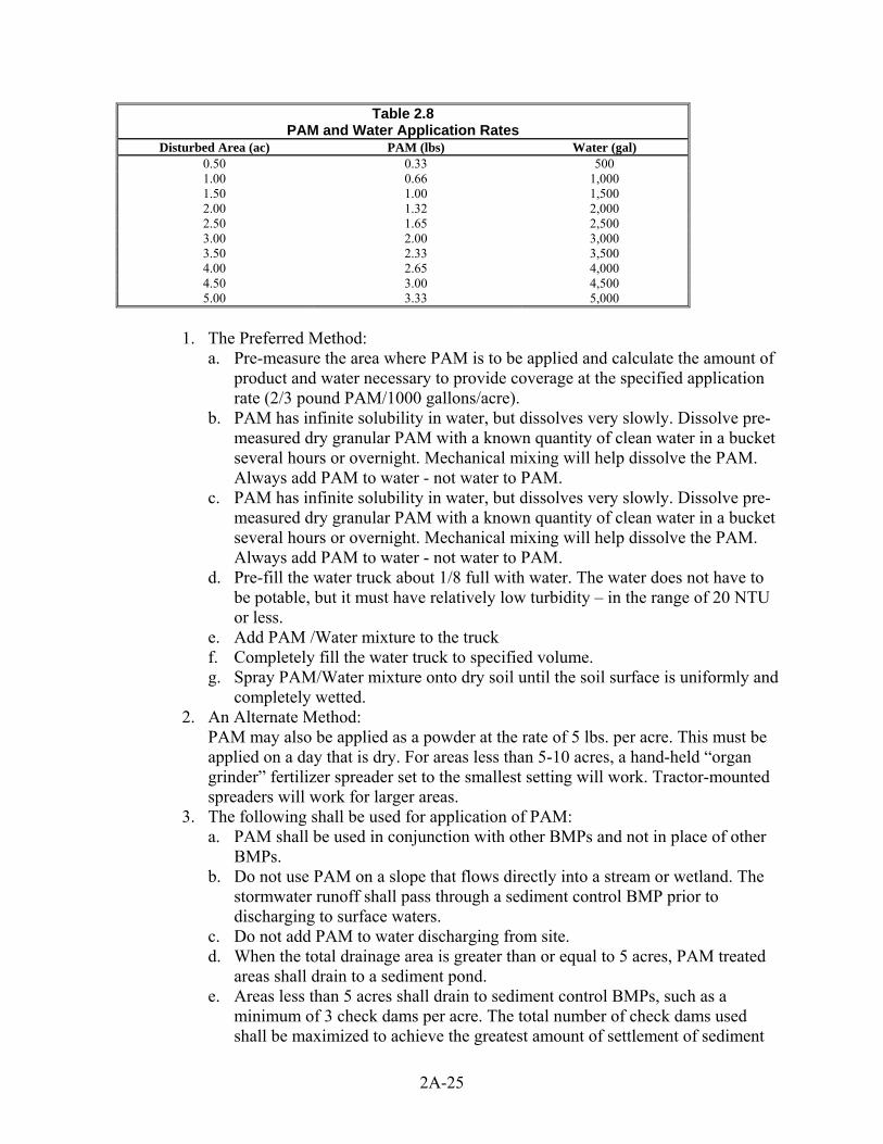
Table 2.8
PAM and Water Application Rates Disturbed Area (ac) PAM (lbs) Water (gal)
0.50 0.33 500 1.00 0.66 1,000 1.50 1.00 1,500 2.00 1.32 2,000 2.50 1.65 2,500 3.00 2.00 3,000 3.50 2.33 3,500 4.00 2.65 4,000 4.50 3.00 4,500 5.00 3.33 5,000
1. The Preferred Method:
a. Pre-measure the area where PAM is to be applied and calculate the amount of product and water necessary to provide coverage at the specified application rate (2/3 pound PAM/1000 gallons/acre).
b. PAM has infinite solubility in water, but dissolves very slowly. Dissolve pre-measured dry granular PAM with a known quantity of clean water in a bucket several hours or overnight. Mechanical mixing will help dissolve the PAM. Always add PAM to water - not water to PAM.
c. PAM has infinite solubility in water, but dissolves very slowly. Dissolve pre-measured dry granular PAM with a known quantity of clean water in a bucket several hours or overnight. Mechanical mixing will help dissolve the PAM. Always add PAM to water - not water to PAM.
d. Pre-fill the water truck about 1/8 full with water. The water does not have to be potable, but it must have relatively low turbidity – in the range of 20 NTU or less.
e. Add PAM /Water mixture to the truck f. Completely fill the water truck to specified volume. g. Spray PAM/Water mixture onto dry soil until the soil surface is uniformly and
completely wetted. 2. An Alternate Method:
PAM may also be applied as a powder at the rate of 5 lbs. per acre. This must be applied on a day that is dry. For areas less than 5-10 acres, a hand-held “organ grinder” fertilizer spreader set to the smallest setting will work. Tractor-mounted spreaders will work for larger areas.
3. The following shall be used for application of PAM: a. PAM shall be used in conjunction with other BMPs and not in place of other
BMPs. b. Do not use PAM on a slope that flows directly into a stream or wetland. The
stormwater runoff shall pass through a sediment control BMP prior to discharging to surface waters.
c. Do not add PAM to water discharging from site. d. When the total drainage area is greater than or equal to 5 acres, PAM treated
areas shall drain to a sediment pond. e. Areas less than 5 acres shall drain to sediment control BMPs, such as a
minimum of 3 check dams per acre. The total number of check dams used shall be maximized to achieve the greatest amount of settlement of sediment
2A-25

prior to discharging from the site. Each check dam shall be spaced evenly in the drainage channel through which stormwater flows are discharged off-site.
f. On all sites, the use of silt fence shall be maximized to limit the discharges of sediment from the site.
g. All areas not being actively worked shall be covered and protected from rainfall. PAM shall not be the only cover BMP used.
h. PAM can be applied to wet soil, but dry soil is preferred due to less i. sediment loss. j. PAM will work when applied to saturated soil but is not as effective as
applications to dry or damp soil. k. Keep the granular PAM supply out of the sun. Granular PAM loses its
effectiveness in three months after exposure to sunlight and air. l. Proper application and re-application plans are necessary to ensure total
effectiveness of PAM usage. m. PAM, combined with water, is very slippery and can be a safety hazard. Care
must be taken to prevent spills of PAM powder onto paved surfaces. During an application of PAM, prevent over-spray from reaching pavement as pavement will become slippery. If PAM powder gets on skin or clothing, wipe it off with a rough towel rather than washing with water-this only makes cleanup messier and take longer.
n. Some PAMs are more toxic and carcinogenic than others. Only the most environmentally safe PAM products should be used.
o. The specific PAM copolymer formulation must be anionic. Cationic PAM shall not be used in any application because of known aquatic toxicity problems. Only the highest drinking water grade PAM, certified for compliance with ANSI/NSF Standard 60 for drinking water treatment, will be used for soil applications. Recent media attention and high interest in PAM has resulted in some entrepreneurial exploitation of the term "polymer." All PAM are polymers, but not all polymers are PAM, and not all PAM products comply with ANSI/NSF Standard 60. PAM use shall be reviewed and approved on a case by case basis by Kitsap County. The Washington State Department of Transportation (WSDOT) has listed approved PAM products on their web page.
p. PAM designated for these uses should be "water soluble" or "linear" or "non-crosslinked". Cross-linked or water absorbent PAM, polymerized in highly acidic (pH<2) conditions, are used to maintain soil moisture content.
q. The PAM anionic charge density may vary from 2-30 percent; a value of 18 percent is typical. Studies conducted by the United States Department of Agriculture (USDA)/ARS demonstrated that soil stabilization was optimized by using very high molecular weight (12-15 mg/mole), highly anionic (>20% hydrolysis) PAM.
r. PAM tackifiers are available and being used in place of guar and alpha plantago. Typically, PAM tackifiers should be used at a rate of no more than 0.5-1 lb. per 1000 gallons of water in a hydromulch machine. Some tackifier product instructions say to use at a rate of 3 –5 lbs. per acre, which can be too much. In addition, pump problems can occur at higher rates due to increased viscosity.
D. Maintenance Standards 1. PAM may be reapplied on actively worked areas after a 48-hour period.
2A-26
2. Reapplication is not required unless PAM treated soil is disturbed or unless turbidity levels show the need for an additional application. If PAM treated soil is left undisturbed a reapplication may be necessary after two months. More PAM applications may be required for steep slopes, silty and clayey soils (USDA Classification Type "C" and "D" soils), long grades, and high precipitation areas. When PAM is applied first to bare soil and then covered with straw, a reapplication may not be necessary for several months.
3. Loss of sediment and PAM may be a basis for penalties per RCW 90.48.080, Discharge of polluting matter in waters prohibited. Such discharge constitutes an illicit discharge, which is prohibited per KCC 12.30.020.
BMP C130: Surface Roughening A. Purpose
Surface roughening aids in the establishment of vegetative cover, reduces runoff velocity, increases infiltration, and provides for sediment trapping through the provision of a rough soil surface. Horizontal depressions are created by operating a tiller or other suitable equipment on the contour or by leaving slopes in a roughened condition by not fine grading them.
B. Conditions for Use 1. All slopes steeper than 3:1 and greater than 5 vertical feet require surface
roughening. 2. Areas with grades steeper than 3:1 should be roughened to a depth of 2 to 4 inches
prior to seeding. 3. Areas that will not be stabilized immediately may be roughened to reduce runoff
velocity until seeding takes place. 4. Slopes with a stable rock face do not require roughening. 5. Slopes where mowing is planned should not be excessively roughened.
C. Design and Installation Specifications There are different methods for achieving a roughened soil surface on a slope, and the selection of an appropriate method depends upon the type of slope. Roughening methods include stair-step grading, grooving, contour furrows, and tracking. See Figure 4.6 for tracking and contour furrows. Factors to be considered in choosing a method are slope steepness, mowing requirements, and whether the slope is formed by cutting or filling. 1. Disturbed areas that will not require mowing may be stair-step graded, grooved,
or left rough after filling. 2. Stair-step grading is particularly appropriate in soils containing large amounts of
soft rock. Each "step" catches material that sloughs from above, and provides a level site where vegetation can become established. Stairs should be wide enough to work with standard earth moving equipment. Stair steps must be on contour or gullies will form on the slope.
3. Areas that will be mowed (these areas should have slopes less steep than 3:1) may have small furrows left by disking, harrowing, raking, or seed-planting machinery operated on the contour.
4. Graded areas with slopes greater than 3:1 but less than 2:1 should be roughened before seeding. This can be accomplished in a variety of ways, including "track walking," or driving a crawler tractor up and down the slope, leaving a pattern of cleat imprints parallel to slope contours.
2A-27

5. Tracking is done by operating equipment up and down the slope to leave horizontal depressions in the soil.
C. Maintenance Standards 1. Areas that are graded in this manner should be seeded as quickly as possible. 2. Regular inspections should be made of the area. If rills appear, they should be re-
graded and re-seeded immediately. Figure 2.6 – Surface Roughening by Tracking and Contour Furrows
2A-28

BMP C131: Gradient Terraces A. Purpose
Gradient terraces reduce erosion damage by intercepting surface runoff and conducting it to a stable outlet at a non-erosive velocity.
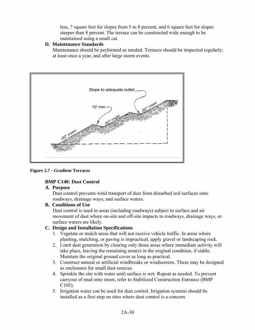
B. Conditions of Use Gradient terraces normally are limited to denuded land having a water erosion problem. They should not be constructed on deep sands or on soils that are too stony, steep, or shallow to permit practical and economical installation and maintenance. Gradient terraces may be used only where suitable outlets are or will be made available. See Figure 2.7 for gradient terraces.
C. Design and Installation Specifications 1. The maximum spacing of gradient terraces should be determined by the following
method: VI = (0.8)s + y Where: VI = vertical interval in feet s = land rise per 100 feet, expressed in feet y = a soil and cover variable with values from 1.0 to 4.0 Values of “y” are influenced by soil erodibility and cover practices. The lower values are applicable to erosive soils where little to no residue is left on the surface. The higher value is applicable only to erosion-resistant soils where a large amount of residue (1½ tons of straw/acre equivalent) is on the surface.
2. The minimum constructed cross-section should meet the design dimensions. 3. The top of the constructed ridge should not be lower at any point than the design
elevation plus the specified overfill for settlement. The opening at the outlet end of the terrace should have a cross section equal to that specified for the terrace channel.
4. Channel grades may be either uniform or variable with a maximum grade of 0.6 feet per 100 feet length. For short distances, terrace grades may be increased to improve alignment. The channel velocity should not exceed that which is nonerosive for the soil type with the planned treatment.
5. All gradient terraces should have adequate outlets. Such an outlet may be a grassed waterway, vegetated area, or tile outlet. In all cases the outlet must convey runoff from the terrace or terrace system to a point where the outflow will not cause damage. Vegetative cover should be used in the outlet channel.
6. The design elevation of the water surface of the terrace should not be lower than the design elevation of the water surface in the outlet at their junction, when both are operating at design flow.
7. Vertical spacing determined by the above methods may be increased as much as 0.5 feet or 10 percent, whichever is greater, to provide better alignment or location, to avoid obstacles, to adjust for equipment size, or to reach a satisfactory outlet.
8. The drainage area above the top should not exceed the area that would be drained by a terrace with normal spacing.
9. The terrace should have enough capacity to handle the peak runoff expected from a 2-year flow as determined by WWHM without overtopping.
10. The terrace cross-section should be proportioned to fit the land slope. The ridge height should include a reasonable settlement factor. The ridge should have a minimum top width of 3 feet at the design height. The minimum cross-sectional area of the terrace channel should be 8 square feet for land slopes of 5 percent or
2A-29
less, 7 square feet for slopes from 5 to 8 percent, and 6 square feet for slopes steeper than 8 percent. The terrace can be constructed wide enough to be maintained using a small cat.
D. Maintenance Standards Maintenance should be performed as needed. Terraces should be inspected regularly; at least once a year, and after large storm events.
Slope to adequate outlet.
10' min.
Figure 2.7 - Gradient Terraces
BMP C140: Dust Control A. Purpose
Dust control prevents wind transport of dust from disturbed soil surfaces onto roadways, drainage ways, and surface waters.
B. Conditions of Use Dust control is used in areas (including roadways) subject to surface and air movement of dust where on-site and off-site impacts to roadways, drainage ways, or surface waters are likely.
C. Design and Installation Specifications 1. Vegetate or mulch areas that will not receive vehicle traffic. In areas where
planting, mulching, or paving is impractical, apply gravel or landscaping rock. 2. Limit dust generation by clearing only those areas where immediate activity will
take place, leaving the remaining area(s) in the original condition, if stable. Maintain the original ground cover as long as practical.
3. Construct natural or artificial windbreaks or windscreens. These may be designed as enclosures for small dust sources.
4. Sprinkle the site with water until surface is wet. Repeat as needed. To prevent carryout of mud onto street, refer to Stabilized Construction Entrance (BMP C105).
5. Irrigation water can be used for dust control. Irrigation systems should be installed as a first step on sites where dust control is a concern.
2A-30

6. Spray exposed soil areas with a dust palliative, following the manufacturer’s instructions and cautions regarding handling and application. Used oil is prohibited from use as a dust suppressant. Other dust palliatives such as calcium chloride or PAM may be approved on a case-by-case basis.
7. PAM (BMP C126) added to water at a rate of 0.5 lbs. per 1,000 gallons of water per acre and applied from a water truck is more effective than water alone. This is due to the increased infiltration of water into the soil and reduced evaporation. In addition, small soil particles are bonded together and are not as easily transported by wind. Adding PAM may actually reduce the quantity of water needed for dust control, especially in eastern Washington.
Techniques that can be used for unpaved roads and lots include: 1. Lower speed limits. High vehicle speed increases the amount of dust stirred up
from unpaved roads and lots. 2. Upgrade the road surface strength by improving particle size, shape, and mineral
types that make up the surface and base materials. 3. Add surface gravel to reduce the source of dust emission. Limit the amount of
fine particles (those smaller than .075 mm) to 10 to 20 percent. 4. Use geotextile fabrics to increase the strength of new roads or roads undergoing
reconstruction. 5. Encourage the use of alternate, paved routes, if available. 6. Restrict use by tracked vehicles and heavy trucks to prevent damage to road
surface and base. 7. Apply chemical dust suppressants using the admix method, blending the product
with the top few inches of surface material. Suppressants may also be applied as surface treatments.
8. Pave unpaved permanent roads and other trafficked areas. 9. Use vacuum street sweepers. 10. Remove mud and other dirt promptly so it does not dry and then turn into dust. 11. Limit dust-causing work on windy days. 12. Contact your local Air Pollution Control Authority for guidance and training on
other dust control measures. Compliance with the local Air Pollution Control Authority constitutes compliance with this BMP.
D. Maintenance Standards Respray area as necessary to keep dust to a minimum.
BMP C150: Materials On Hand A. Purpose
Quantities of erosion prevention and sediment control materials can be kept on the project site at all times to be used for emergency situations such as unexpected heavy summer rains. Having these materials on-site reduces the time needed to implement BMPs when inspections indicate that existing BMPs are not meeting the Construction SWPPP requirements. In addition, contractors can save money by buying some materials in bulk and storing them at their office or yard.
B. Conditions of Use 1. Construction projects of any size or type can benefit from having materials on
hand. A small commercial development project could have a roll of plastic and some gravel available for immediate protection of bare soil and temporary berm construction. A large earthwork project, such as highway construction, might
2A-31

have several tons of straw, several rolls of plastic, flexible pipe, sandbags, geotextile fabric and steel “T” posts.
2. Materials are stockpiled and readily available before any site clearing, grubbing, or earthwork begins. A large contractor or developer could keep a stockpile of materials that are available to be used on several projects.
3. If storage space at the project site is at a premium, the contractor could maintain the materials at their office or yard. The office or yard must be less than an hour from the project site.
C. Design and Installation Specifications Depending on project type, size, complexity, and length, materials and quantities will vary. A good minimum that will cover numerous situations includes: Material Measure Quantity
Clear Plastic, 6 mil 100 foot roll 1-2 Drainpipe, 6 or 8 inch diameter 25 foot section 4-6 Sandbags, filled each 25-50 Straw Bales for mulching, approx. 50# each 10-20 Quarry Spalls ton 2-4 Washed Gravel cubic yard 2-4 Geotextile Fabric 100 foot roll 1-2 Catch Basin Inserts each 2-4 Steel “T” Posts each 12-24
D. Maintenance Standards 1. All materials with the exception of the quarry spalls, steel “T” posts, and gravel
should be kept covered and out of both sun and rain. 2. Re-stock materials used as needed.
BMP C151: Concrete Handling A. Purpose
1. Concrete work can generate process water and slurry that contain fine particles and high pH, both of which can violate water quality standards in the receiving water. This BMP is intended to minimize and eliminate concrete process water and slurry from entering waters of the state.
B. Conditions of Use Any time concrete is used, these management practices shall be utilized. Concrete construction projects include, but are not limited to, the following: 1. Curbs 2. Sidewalks 3. Roads 4. Bridges 5. Foundations 6. Floors 7. Runways
C. Design and Installation Specifications 1. Concrete truck chutes, pumps, and internals shall be washed out only into formed
areas awaiting installation of concrete or asphalt.
2A-32

2. Unused concrete remaining in the truck and pump shall be returned to the originating batch plant for recycling.
3. Hand tools including, but not limited to, screeds, shovels, rakes, floats, and trowels shall be washed off only into formed areas awaiting installation of concrete or asphalt.
4. Equipment that cannot be easily moved, such as concrete pavers, shall only be washed in areas that do not directly drain to natural or constructed stormwater conveyances.
5. Washdown from areas such as concrete aggregate driveways shall not drain directly to natural or constructed stormwater conveyances.
6. When no formed areas are available, washwater and leftover product shall be contained in a lined container. Contained concrete shall be disposed of in a manner that does not violate groundwater or surface water quality standards.
D. Maintenance Standards Containers shall be checked for holes in the liner daily during concrete pours and repaired the same day.
BMP C152: Sawcutting and Surfacing Pollution Prevention A. Purpose
Sawcutting and surfacing operations generate slurry and process water that contains fine particles and high pH (concrete cutting), both of which can violate the water quality standards in the receiving water. This BMP is intended to minimize and eliminate process water and slurry from entering waters of the State.
B. Conditions of Use Anytime saw cutting or surfacing operations take place, these management practices shall be utilized. Sawcutting and surfacing operations include, but are not limited to, the following: 1. Sawing 2. Coring 3. Grinding 4. Roughening 5. Hydro-demolition 6. Bridge and road surfacing
C. Design and Installation Specifications 1. Slurry and cuttings shall be vacuumed during cutting and surfacing operations. 2. Slurry and cuttings shall not remain on permanent concrete or asphalt pavement
overnight. 3. Slurry and cuttings shall not drain to any natural or constructed drainage
conveyance. 4. Collected slurry and cuttings shall be disposed of in a manner that does not violate
groundwater or surface water quality standards. 5. Process water that is generated during hydro-demolition, surface roughening or
similar operations shall not drain to any natural or constructed drainage conveyance and shall be disposed of in a manner that does not violate groundwater or surface water quality standards.
6. Cleaning waste material and demolition debris shall be handled and disposed of in a manner that does not cause contamination of water. If the area is swept with a pick-up sweeper, the material must be hauled out of the area to an appropriate disposal site.
2A-33

D. Maintenance Standards Continually monitor operations to determine whether slurry, cuttings, or process water could enter waters of the state. If inspections show that a violation of water quality standards could occur, stop operations and immediately implement preventive measures such as berms, barriers, secondary containment, and vacuum trucks.
BMP C153: Material Delivery, Storage and Containment A. Purpose
Prevent, reduce, or eliminate the discharge of pollutants from material delivery and storage to the stormwater system or watercourses by minimizing the storage of hazardous materials onsite, storing materials in a designated area, and installing secondary containment.
B. Conditions of Use These procedures are suitable for use at all construction sites with delivery and storage of the following materials: 1. Petroleum products such as fuel, oil and grease 2. Soil stabilizers and binders (e.g. Polyacrylamide) 3. Fertilizers, pesticides and herbicides 4. Detergents 5. Asphalt and concrete compounds 6. Hazardous chemicals such as acids, lime, adhesives, paints, solvents and curing
compounds 7. Any other material that may be detrimental if released to the environment
C. Design and Installation Specifications The following steps should be taken to minimize risk: 1. Temporary storage area should be located away from vehicular traffic, near the
construction entrance(s), and away from waterways or storm drains. 2. Material Safety Data Sheets (MSDS) should be supplied for all materials stored.
Chemicals should be kept in their original labeled containers. 3. Hazardous material storage on-site should be minimized. 4. Hazardous materials should be handled as infrequently as possible. 5. During the wet weather season (Oct 1 – April 30), consider storing materials in a
covered area. 6. Materials should be stored in secondary containments, such as earthen dike, horse
trough, or even a children’s wading pool for non-reactive materials such as detergents, oil, grease, and paints. Small amounts of material may be secondarily contained in “bus boy” trays or concrete mixing trays.
7. Do not store chemicals, drums, or bagged materials directly on the ground. Place these items on a pallet and, when possible, in secondary containment.
8. If drums must be kept uncovered, store them at a slight angle to reduce ponding of rainwater on the lids to reduce corrosion. Domed plastic covers are inexpensive and snap to the top of drums, preventing water from collecting.
D. Material Storage Areas and Secondary Containment Practices: 1. Liquids, petroleum products, and substances listed in 40 CFR Parts 110, 117, or
302 shall be stored in approved containers and drums and shall not be overfilled. Containers and drums shall be stored in temporary secondary containment facilities.
2. Temporary secondary containment facilities shall provide for a spill containment volume able to contain precipitation from a 25 year, 24 hour storm event, plus
2A-34

10% of the total enclosed container volume of all containers, or 110% of the capacity of the largest container within its boundary, whichever is greater.
3. Secondary containment facilities shall be impervious to the materials stored therein for a minimum contact time of 72 hours.
4. Secondary containment facilities shall be maintained free of accumulated rainwater and spills. In the event of spills or leaks, accumulated rainwater and spills shall be collected and placed into drums. These liquids shall be handled as hazardous waste unless testing determines them to be non-hazardous.
5. Sufficient separation should be provided between stored containers to allow for spill cleanup and emergency response access.
6. During the wet weather season (Oct 1 – April 30), each secondary containment facility shall be covered during non-working days, prior to and during rain events.
7. Keep material storage areas clean, organized and equipped with an ample supply of appropriate spill clean-up material (spill kit).
8. The spill kit should include, at a minimum: a. 1-Water Resistant Nylon Bag b. 3-Oil Absorbent Socks 3”x 4’ c. 2-Oil Absorbent Socks 3”x 10’ d. 12-Oil Absorbent Pads 17”x19” e. 1-Pair Splash Resistant Goggles f. 3-Pair Nitrile Gloves g. 10-Disposable Bags with Ties h. Instructions
BMP C160: Certified Erosion and Sediment Control Lead A. Purpose
The project proponent designates at least one person as the responsible representative in charge of erosion and sediment control (ESC), and water quality protection. The designated person shall be the Certified Erosion and Sediment Control Lead (CESCL) who is responsible for ensuring compliance with all local, state, and federal erosion and sediment control and water quality requirements.
B. Conditions of Use A CESCL shall be made available on all projects one acre or larger that discharge stormwater to surface waters of the state. The CESCL shall: 1. Have a current certificate proving attendance in an erosion and sediment control
training course that meets the minimum ESC training and certification requirements established by Ecology (see details below). Ecology will maintain a list of ESC training and certification providers at: http://www.ecy.wa.gov/programs/wq/stormwater/cescl.htm
OR
2. Be a Certified Professional in Erosion and Sediment Control (CPESC); for additional information go to: www.cpesc.net
C. Specifications 1. Certification shall remain valid for three years. 2. The CESCL shall have authority to act on behalf of the contractor or developer
and shall be available, on call, 24 hours per day throughout the period of construction.
2A-35
3. The Construction SWPPP shall include the name, telephone number, fax number, and address of the designated CESCL.
4. A CESCL may provide inspection and compliance services for multiple construction projects in the same geographic region. Duties and responsibilities of the CESCL shall include, but are not limited to the following: a. Maintaining permit file on site at all times which includes the SWPPP and any
associated permits and plans. b. Directing BMP installation, inspection, maintenance, modification, and
removal. c. Updating all project drawings and the Construction SWPPP with changes
made. d. Keeping daily logs, and inspection reports. Inspection reports should include:
1) Inspection date/time. 2) Weather information; general conditions during inspection and
approximate amount of precipitation since the last inspection. 3) A summary or list of all BMPs implemented, including observations of all
erosion/sediment control structures or practices. The following shall be noted: a) Locations of BMPs inspected, b) Locations of BMPs that need maintenance, c) Locations of BMPs that failed to operate as designed or intended, and d) Locations of where additional or different BMPs are required.
5. Visual monitoring results, including a description of discharged stormwater. The presence of suspended sediment, turbid water, discoloration, and oil sheen shall be noted, as applicable.
6. Any water quality monitoring performed during inspection. 7. General comments and notes, including a brief description of any BMP repairs,
maintenance or installations made as a result of the inspection. 8. Facilitate, participate in, and take corrective actions resulting from inspections
performed by outside agencies or the owner.
BMP C162: Scheduling A. Purpose
Sequencing a construction project reduces the amount and duration of soil exposed to erosion by wind, rain, runoff, and vehicle tracking.
B. Conditions of Use The construction sequence schedule is an orderly listing of all major land-disturbing activities together with the necessary erosion and sedimentation control measures planned for the project. This type of schedule guides the contractor on work to be done before other work is started so that serious erosion and sedimentation problems can be avoided. Following a specified work schedule that coordinates the timing of land disturbing activities and the installation of control measures is perhaps the most cost-effective way of controlling erosion during construction. The removal of surface ground cover leaves a site vulnerable to accelerated erosion. Construction procedures that limit land clearing, provide timely installation of erosion and sedimentation controls, and restore protective cover quickly can significantly reduce the erosion potential of a site.
2A-36

C. Design Considerations 1. Avoid rainy periods. 2. Schedule projects to disturb only small portions of the site at any one time.
Complete grading as soon as possible. Immediately stabilize the disturbed portion before grading the next portion. Practice staged seeding in order to revegetate cut and fill slopes as the work progresses.
BMP C180: Small Project Construction Stormwater Pollution Prevention A. Purpose
To prevent the discharge of sediment and other pollutants to the maximum extent practicable from small construction projects.
B. Conditions of Use On small construction projects, those adding or replacing less than 2,000 square feet of impervious surface or clearing less than 7,000 square feet.
C. Design and Installation Specifications 1. Plan and implement proper clearing and grading of the site. It is most important
only to clear the areas needed, thus keeping exposed areas to a minimum. Phase clearing so that only those areas that are actively being worked are uncovered. Note: Clearing limits should be flagged in the lot or area prior to initiating clearing.
2. Soil shall be managed in a manner that does not permanently compact or deteriorate the final soil and landscape system. If disturbance and/or compaction occur the impact must be corrected at the end of the construction activity. This shall include restoration of soil depth, soil quality, permeability, and percent organic matter. Construction practices must not cause damage to or compromise the design of permanent landscape or infiltration areas.
3. Locate excavated basement soil a reasonable distance behind the curb, such as in the backyard or side yard area. This will increase the distance eroded soil must travel to reach the storm sewer system. Soil piles should be covered until the soil is either used or removed. Piles should be situated so that sediment does not run into the street or adjoining yards.
4. Backfill basement walls as soon as possible and rough grade the lot. This will eliminate large soil mounds, which are highly erodible, and prepares the lot for temporary cover, which will further reduce erosion potential.
5. Remove excess soil from the site as soon as possible after backfilling. This will eliminate any sediment loss from surplus fill.
6. If a lot has a soil bank higher than the curb, a trench or berm should be installed moving the bank several feet behind the curb. This will reduce the occurrence of gully and rill erosion while providing a storage and settling area for stormwater.
7. The construction entrance should be stabilized where traffic will be leaving the construction site and traveling on paved roads or other paved areas within 1,000 feet of the site.
8. Provide for periodic street cleaning to remove any sediment that may have been tracked out. Sediment should be removed by shoveling or sweeping and carefully removed to a suitable disposal area where it will not be re-eroded.
9. Utility trenches that run up and down slopes must be backfilled within seven days. Cross-slope trenches may remain open throughout construction to provide runoff interception and sediment trapping, provided that they do not convey turbid runoff off site.
2A-37

2.2 RUNOFF CONVEYANCE AND TREATMENT BMPS
BMP C200: Interceptor Dike and Swale A. Purpose
Provide a ridge of compacted soil, or a ridge with an upslope swale, at the top or base of a disturbed slope or along the perimeter of a disturbed construction area to convey stormwater. Use the dike and/or swale to intercept the runoff from unprotected areas and direct it to areas where erosion can be controlled. This can prevent storm runoff from entering the work area or sediment-laden runoff from leaving the construction site.
B. Conditions of Use Where the runoff from an exposed site or disturbed slope must be conveyed to an erosion control facility, which can safely convey the stormwater. 1. Locate upslope of a construction site to prevent runoff from entering disturbed
area. 2. When placed horizontally across a disturbed slope, it reduces the amount and
velocity of runoff flowing down the slope. 3. Locate downslope to collect runoff from a disturbed area and direct it to a
sediment basin. C. Design and Installation Specifications
1. Dike and/or swale and channel must be stabilized with temporary or permanent vegetation or other channel protection during construction.
2. Channel requires a positive grade for drainage; steeper grades require channel protection and check dams.
3. Review construction for areas where overtopping may occur. 4. Can be used at top of new fill before vegetation is established. 5. May be used as a permanent diversion channel to carry the runoff. 6. Sub-basin tributary area should be one acre or less. 7. Design capacity for 1.6 times the 10-year, 1-hour flow indicated by an approved
continuous runoff model for temporary facilities. 8. Interceptor dikes shall meet the following criteria:
a. Top Width 2 feet minimum. b. Height 1.5 feet minimum on berm. c. Side Slope 2:1 or flatter. d. Grade depends on topography, however, dike system minimum is 0.5%,
maximum is 1%. e. Compaction Minimum of 90 percent ASTM D698 standard proctor.
9. Horizontal Spacing of Interceptor Dikes:
Average Slope Slope Percent Flowpath Length 20H:1V or less 3-5% 300 feet (10 to 20)H:1V 5-10% 200 feet (4 to 10)H:1V 10-25% 100 feet (2 to 4)H:1V 25-50% 50 feet Stabilization depends on velocity and reach
2A-38

Slopes <5% Seed and mulch applied within 5 days of dike construction (see BMP C121, Mulching).
10. Slopes 5 - 40% Dependent on runoff velocities and dike materials. Stabilization should be done immediately using either sod or riprap or other measures to avoid erosion.
11. The upslope side of the dike shall provide positive drainage to the dike outlet. No erosion shall occur at the outlet. Provide energy dissipation measures as necessary. Sediment-laden runoff must be released through a sediment trapping facility.
12. Minimize construction traffic over temporary dikes. Use temporary cross culverts for channel crossing.
13. Interceptor swales shall meet the following criteria: Bottom Width 2 feet minimum; the bottom shall be level. Depth 1-foot minimum. Side Slope 2:1 or flatter. Grade Maximum 5 percent, with positive drainage to a suitable outlet (such as a sediment pond). Stabilization Seed as per BMP C120, Temporary and Permanent Seeding, or BMP C202, Channel Lining, 12 inches thick of riprap pressed into the bank and extending at least 8 inches vertical from the bottom.
14. Inspect diversion dikes and interceptor swales once a week and after every rainfall. Immediately remove sediment from the flow area.
15. Damage caused by construction traffic or other activity must be repaired before the end of each working day.
16. Check outlets and make timely repairs as needed to avoid gully formation. When the area below the temporary diversion dike is permanently stabilized, remove the dike and fill and stabilize the channel to blend with the natural surface.
BMP C201: Grass-Lined Channels A. Purpose
To provide a channel with a vegetative lining for conveyance of runoff. See Figure 2.8 for typical grass-lined channels.
B. Conditions of Use This practice applies to construction sites where concentrated runoff needs to be contained to prevent erosion or flooding. 1. When a vegetative lining can provide sufficient stability for the channel cross
section and at lower velocities of water (normally dependent on grade). This means that the channel slopes are generally less than 5 percent and space is available for a relatively large cross section.
2. Typical uses include roadside ditches, channels at property boundaries, outlets for diversions, and other channels and drainage ditches in low areas.
3. Channels that will be vegetated should be installed before major earthwork and hydroseeded with a bonded fiber matrix (BFM). The vegetation should be well established (i.e., 75 percent cover) before water is allowed to flow in the ditch. With channels that will have high flows, erosion control blankets should be installed over the hydroseed. If vegetation cannot be established from seed before water is allowed in the ditch, sod should be installed in the bottom of the ditch in lieu of hydromulch and blankets.
2A-39

C. Design and Installation Specifications 1. Locate the channel where it can conform to the topography and other features
such as roads. 2. Locate them to use natural drainage systems to the greatest extent possible. 3. Avoid sharp changes in alignment or bends and changes in grade. 4. Do not reshape the landscape to fit the drainage channel. 5. The maximum design velocity shall be based on soil conditions, type of
vegetation, and method of revegetation, but at no times shall velocity exceed 5 feet/second. The channel shall not be overtopped by the peak runoff. Use 1.6 times the 10-year, 1-hour flow indicated by an approved continuous runoff model to determine a flow rate, which the channel must contain.
6. Where the grass-lined channel will also function as a permanent stormwater conveyance facility, consultant the drainage conveyance requirements of the local government with jurisdiction.
7. An established grass or vegetated lining is required before the channel can be used to convey stormwater, unless stabilized with nets or blankets.
8. If design velocity of a channel to be vegetated by seeding exceeds 2 ft/sec, a temporary channel liner is required. Geotextile or special mulch protection such as fiberglass roving or straw and netting provide stability until the vegetation is fully established. See Figure 2.9.
9. Check dams shall be removed when the grass has matured sufficiently to protect the ditch or swale unless the slope of the swale is greater than 4 percent. The area beneath the check dams shall be seeded and mulched immediately after dam removal.
10. If vegetation is established by sodding, the permissible velocity for established vegetation may be used and no temporary liner is needed.
11. Do not subject grass-lined channel to sedimentation from disturbed areas. Use sediment-trapping BMPs upstream of the channel.
12. V-shaped grass channels generally apply where the quantity of water is small, such as in short reaches along roadsides. The V-shaped cross section is least desirable because it is difficult to stabilize the bottom where velocities may be high.
13. Trapezoidal grass channels are used where runoff volumes are large and slope is low so that velocities are nonerosive to vegetated linings. (Note: it is difficult to construct small parabolic shaped channels.)
14. Subsurface drainage, or riprap channel bottoms, may be necessary on sites that are subject to prolonged wet conditions due to long duration flows or a high water table.
15. Provide outlet protection at culvert ends and at channel intersections. 16. Grass channels, at a minimum, should carry peak runoff for temporary
construction drainage facilities from 1.6 times the 1-hour flow indicated by an approved continuous runoff model without eroding. Where flood hazard exists, increase the capacity according to the potential damage.
17. Grassed channel side slopes generally are constructed 3:1 or flatter to aid in the establishment of vegetation and for maintenance.
18. Construct channels a minimum of 0.2 foot larger around the periphery to allow for soil bulking during seedbed preparations and sod buildup.
D. Maintenance Standards 1. During the establishment period, check grass-lined channels after every rainfall.
2A-40

2. After grass is established, periodically check the channel; check it after every heavy rainfall event. Immediately make repairs.
3. It is particularly important to check the channel outlet and all road crossings for bank stability and evidence of piping or scour holes.
4. Remove all significant sediment accumulations to maintain the designed carrying capacity. Keep the grass in a healthy, vigorous condition at all times, since it is the primary erosion protection for the channel.
Figure 2.8 – Typical Grass-Lined Channels
2A-41
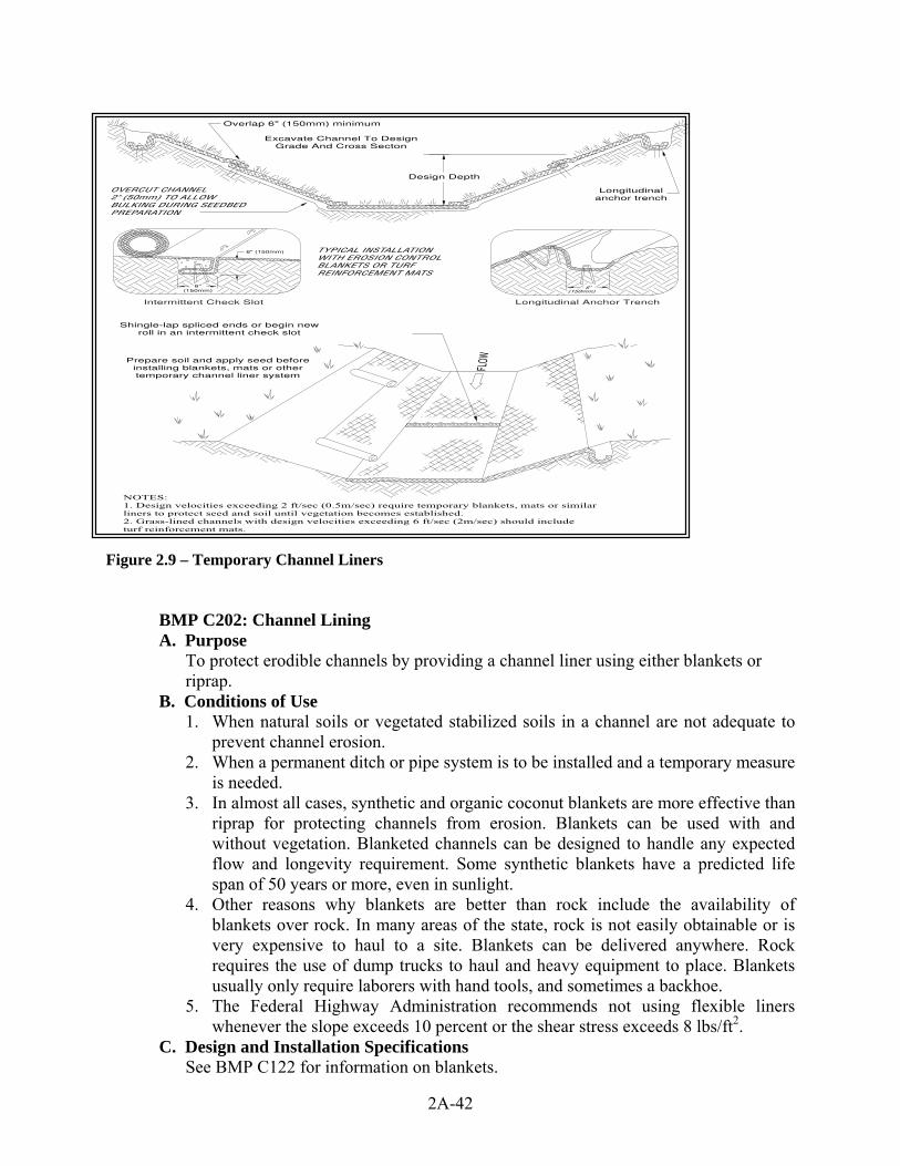
Figure 2.9 – Temporary Channel Liners
BMP C202: Channel Lining A. Purpose
To protect erodible channels by providing a channel liner using either blankets or riprap.
B. Conditions of Use 1. When natural soils or vegetated stabilized soils in a channel are not adequate to
prevent channel erosion. 2. When a permanent ditch or pipe system is to be installed and a temporary measure
is needed. 3. In almost all cases, synthetic and organic coconut blankets are more effective than
riprap for protecting channels from erosion. Blankets can be used with and without vegetation. Blanketed channels can be designed to handle any expected flow and longevity requirement. Some synthetic blankets have a predicted life span of 50 years or more, even in sunlight.
4. Other reasons why blankets are better than rock include the availability of blankets over rock. In many areas of the state, rock is not easily obtainable or is very expensive to haul to a site. Blankets can be delivered anywhere. Rock requires the use of dump trucks to haul and heavy equipment to place. Blankets usually only require laborers with hand tools, and sometimes a backhoe.
5. The Federal Highway Administration recommends not using flexible liners whenever the slope exceeds 10 percent or the shear stress exceeds 8 lbs/ft2.
C. Design and Installation Specifications See BMP C122 for information on blankets.
2A-42

1. Since riprap is used where erosion potential is high, construction must be sequenced so that the riprap is put in place with the minimum possible delay.
2. Disturbance of areas where riprap is to be placed should be undertaken only when final preparation and placement of the riprap can follow immediately behind the initial disturbance. Where riprap is used for outlet protection, the riprap should be placed before or in conjunction with the construction of the pipe or channel so that it is in place when the pipe or channel begins to operate.
3. The designer, after determining the riprap size that will be stable under the flow conditions, shall consider that size to be a minimum size and then, based on riprap gradations actually available in the area, select the size or sizes that equal or exceed the minimum size. The possibility of drainage structure damage by children shall be considered in selecting a riprap size, especially if there is nearby water or a gully in which to toss the stones.
4. Stone for riprap shall consist of field stone or quarry stone of approximately rectangular shape. The stone shall be hard and angular and of such quality that it will not disintegrate on exposure to water or weathering and it shall be suitable in all respects for the purpose intended.
5. Rubble concrete may be used provided it has a density of at least 150 pounds per cubic foot, and otherwise meets the requirement of this standard and specification.
6. A lining of engineering filter fabric (geotextile) shall be placed between the riprap and the underlying soil surface to prevent soil movement into or through the riprap. The geotextile should be keyed in at the top of the bank.
7. Filter fabric shall not be used on slopes greater than 1-1/2:1 as slippage may occur. It should be used in conjunction with a layer of coarse aggregate (granular filter blanket) when the riprap to be placed is 12 inches and larger.
BMP C203: Water Bars A. Purpose
A small ditch or ridge of material is constructed diagonally across a road or right-of-way to divert stormwater runoff from the road surface, wheel tracks, or a shallow road ditch.
B. Conditions of Use Clearing right-of-way and construction of access for power lines, pipelines, and other similar installations often require long narrow right-of-ways over sloping terrain. Disturbance and compaction promotes gully formation in these cleared strips by increasing the volume and velocity of runoff. Gully formation may be especially severe in tire tracks and ruts. To prevent gullying, runoff can often be diverted across the width of the right-of-way to undisturbed areas by using small predesigned diversions. 1. Give special consideration to each individual outlet area, as well as to the
cumulative effect of added diversions. Use gravel to stabilize the diversion where significant vehicular traffic is anticipated.
C. Design and Installation Specifications 1. Height: 8-inch minimum measured from the channel bottom to the ridge top 2. Side slope of channel: 2:1 maximum; 3:1 or flatter when vehicles will cross. 3. Base width of ridge: 6-inch minimum. 4. Locate them to use natural drainage systems and to discharge into well vegetated
stable areas. 5. Guideline for spacing:
2A-43

Slope % Spacing (ft) < 5 125 5 - 10 100 10 - 20 75 20 - 35 50 > 35 Use rock lined ditch
6. Grade of water bar and angle: Select angle that results in ditch slope less than 2 percent.
7. Install as soon as the clearing and grading is complete. Reconstruct when construction is complete on a section when utilities are being installed.
8. Compact the ridge when installed. 9. Stabilize, seed and mulch the portions that are not subject to traffic. 10. Gravel the areas crossed by vehicles.
D. Maintenance Standards 1. Periodically inspect right-of-way diversions for wear and after every heavy
rainfall for erosion damage. 2. Immediately remove sediment from the flow area and repair the dike. 3. Check outlet areas and make timely repairs as needed. 4. When permanent road drainage is established and the area above the temporary
right-of-way diversion is permanently stabilized, remove the dike and fill the channel to blend with the natural ground, and appropriately stabilize the disturbed area.
BMP C204: Pipe Slope Drains A. Purpose
To use a pipe to convey stormwater anytime water needs to be diverted away from or over bare soil to prevent gullies, channel erosion, and saturation of slide-prone soils.
B. Conditions of Use Pipe slope drains should be used when a temporary or permanent stormwater conveyance is needed to move the water down a steep slope to avoid erosion (Figure 2.10). On highway projects, they should be used at bridge ends to collect runoff and pipe it to the base of the fill slopes along bridge approaches. These can be designed into a project and included as bid items. Another use on road projects is to collect runoff from pavement and pipe it away from side slopes. These are useful because there is generally a time lag between having the first lift of asphalt installed and the curbs, gutters, and permanent drainage installed. Used in conjunction with sand bags, or other temporary diversion devices, these will prevent massive amounts of sediment from leaving a project. Water can be collected, channeled with sand bags, Triangular Silt Dikes, berms, or other material, and piped to temporary sediment ponds. Pipe slope drains can be: 1. Connected to new catch basins and used temporarily until all permanent piping is
installed; 2. Used to drain water collected from aquifers exposed on cut slopes and take it to
the base of the slope; 3. Used to collect clean runoff from plastic sheeting and direct it away from exposed
soil; 4. Installed in conjunction with silt fence to drain collected water to a controlled
area;
2A-44

5. Used to divert small seasonal streams away from construction. They have been used successfully on culvert replacement and extension jobs. Large flex pipe can be used on larger streams during culvert removal, repair, or replacement; and,
6. Connected to existing down spouts and roof drains and used to divert water away from work areas during building renovation, demolition, and construction projects.
There are now several commercially available collectors that are attached to the pipe inlet and help prevent erosion at the inlet.
C. Design and Installation Specifications Size the pipe to convey the flow. The capacity for temporary drains shall be sufficient to handle the peak flow from 1.6 times the 10-year, 1-hour flow indicated by an approved continuous runoff model.
Peak flow from the developed 100-year 24-hour event shall be used for sizing permanent pipe slope drains. 1. Use care in clearing vegetated slopes for installation. 2. Re-establish cover immediately on areas disturbed by installation. 3. Use temporary drains on new cut or fill slopes. 4. Use diversion dikes or swales to collect water at the top of the slope. 5. Ensure that the entrance area is stable and large enough to direct flow into the
pipe. 6. Piping of water through the berm at the entrance area is a common failure mode. 7. The entrance shall consist of a standard flared end section for culverts 12 inches
and larger with a minimum 6-inch metal toe plate to prevent runoff from undercutting the pipe inlet. The slope of the entrance shall be at least 3 percent. Sand bags may also be used at pipe entrances as a temporary measure.
8. The soil around and under the pipe and entrance section shall be thoroughly compacted to prevent undercutting.
9. The flared inlet section shall be securely connected to the slope drain and have watertight connecting bands.
10. Slope drain sections shall be securely fastened together, fused or have gasketed watertight fittings, and shall be securely anchored into the soil.
11. Thrust blocks should be installed anytime 90 degree bends are utilized. 12. Depending on size of pipe and flow, these can be constructed with sand bags,
straw bales staked in place, “t” posts and wire, or ecology blocks. 13. Pipe needs to be secured along its full length to prevent movement. This can be
done with steel “t” posts and wire. A post is installed on each side of the pipe and the pipe is wired to them. This should be done every 10-20 feet of pipe length or so, depending on the size of the pipe and quantity of water to diverted.
14. Interceptor dikes shall be used to direct runoff into a slope drain. The height of the dike shall be at least 1 foot higher at all points than the top of the inlet pipe.
15. The area below the outlet must be stabilized with a riprap apron (see BMP C209 Outlet Protection, for the appropriate outlet material).
16. If the pipe slope drain is conveying sediment-laden water, direct all flows into the sediment trapping facility.
17. Materials specifications for any permanent piped system shall be set by the local government.
2A-45

2A-46
D. Maintenance Standards Check inlet and outlet points regularly, especially after storms. The inlet should be free of undercutting, and no water should be going around the point of entry. If there are problems, the headwall should be reinforced with compacted earth or sand bags. 1. The outlet point should be free of erosion and installed with appropriate outlet
protection. 2. For permanent installations, inspect pipe periodically for vandalism and physical
distress such as slides and wind-throw. 3. Normally the pipe slope is so steep that clogging is not a problem with smooth
wall pipe, however, debris may become lodged in the pipe. Dike material compacted
90% modified proctor
CPEP or equivalent pipe
Discharge to a stabilizedwatercourse, sediment retentionfacility, or stabilized outlet
Inlet and all sections must besecurely fastened togetherwith gasketed watertight fittings
Provide riprap pador equivalent energydissipation
Interceptor Dike
Standard flaredend section
Figure 2.10 - Pipe Slope Drain
BMP C205: Subsurface Drains A. Purpose
To intercept, collect, and convey ground water to a satisfactory outlet, using a perforated pipe or conduit below the ground surface. Subsurface drains are also known as “french drains.” The perforated pipe provides a dewatering mechanism to drain excessively wet soils, provide a stable base for construction, improve stability of structures with shallow foundations, or to reduce hydrostatic pressure to improve slope stability.
B. Conditions of Use Use when excessive water must be removed from the soil. The soil permeability, depth to water table and impervious layers are all factors which may govern the use of subsurface drains.

C. Design and Installation Specifications 1. Relief drains are used either to lower the water table in large, relatively flat areas,
improve the growth of vegetation, or to remove surface water. They are installed along a slope and drain in the direction of the slope. They can be installed in a grid pattern, a herringbone pattern, or a random pattern.
2. Interceptor drains are used to remove excess ground water from a slope, stabilize steep slopes, and lower the water table immediately below a slope to prevent the soil from becoming saturated. They are installed perpendicular to a slope and drain to the side of the slope. They usually consist of a single pipe or series of single pipes instead of a patterned layout.
3. Depth and spacing of interceptor drains - The depth of an interceptor drain is determined primarily by the depth to which the water table is to be lowered or the depth to a confining layer. For practical reasons, the maximum depth is usually limited to 6 feet, with a minimum cover of 2 feet to protect the conduit.
4. The soil should have depth and sufficient permeability to permit installation of an effective drainage system at a depth of 2 to 6 feet. An adequate outlet for the drainage system must be available either by gravity or by pumping.
5. The quantity and quality of discharge needs to be accounted for in the receiving stream (additional detention may be required).
6. This standard does not apply to subsurface drains for building foundations or deep excavations.
7. The capacity of an interceptor drain is determined by calculating the maximum rate of ground water flow to be intercepted. Therefore, it is good practice to make complete subsurface investigations, including hydraulic conductivity of the soil, before designing a subsurface drainage system.
8. Size of drain--Size subsurface drains to carry the required capacity without pressure flow. Minimum diameter for a subsurface drain is 4 inches.
9. The minimum velocity required to prevent silting is 1.4 ft./sec. The line shall be graded to achieve this velocity at a minimum. The maximum allowable velocity using a sand-gravel filter or envelope is 9 ft/sec.
10. Filter material and fabric shall be used around all drains for proper bedding and filtration of fine materials. Envelopes and filters should surround the drain to a minimum of 3-inch thickness.
11. The outlet of the subsurface drain shall empty into a sediment pond through a catch basin. If free of sediment, it can then empty into a receiving channel, swale, or stable vegetated area adequately protected from erosion and undermining.
12. The trench shall be constructed on a continuous grade with no reverse grades or low spots.
13. Soft or yielding soils under the drain shall be stabilized with gravel or other suitable material.
14. Backfilling shall be done immediately after placement of the pipe. No sections of pipe shall remain uncovered overnight or during a rainstorm. Backfill material shall be placed in the trench in such a manner that the drain pipe is not displaced or damaged.
15. • Do not install permanent drains near trees to avoid the tree roots that tend to clog the line. Use solid pipe with watertight connections where it is necessary to pass a subsurface drainage system through a stand of trees.
16. Outlet - Ensure that the outlet of a drain empties into a channel or other watercourse above the normal water level.
2A-47

17. Secure an animal guard to the outlet end of the pipe to keep out rodents. 18. Use outlet pipe of corrugated metal, cast iron, or heavy-duty plastic without
perforations and at least 10 feet long. Do not use an envelope or filter material around the outlet pipe, and bury at least two-thirds of the pipe length.
19. When outlet velocities exceed those allowable for the receiving stream, outlet protection must be provided.
D. Maintenance Standards Subsurface drains shall be checked periodically to ensure that they are free-flowing and not clogged with sediment or roots. 1. The outlet shall be kept clean and free of debris. 2. Surface inlets shall be kept open and free of sediment and other debris. 3. Trees located too close to a subsurface drain often clog the system with their
roots. If a drain becomes clogged, relocate the drain or remove the trees as a last resort. Drain placement should be planned to minimize this problem.
4. Where drains are crossed by heavy vehicles, the line shall be checked to ensure that it is not crushed.
BMP C206: Level Spreader A. Purpose To provide a temporary outlet for dikes and diversions consisting of an excavated depression constructed at zero grade across a slope. To convert concentrated runoff to sheet flow and release it onto areas stabilized by existing vegetation or an engineered filter strip. B. Conditions of Use
Used when a concentrated flow of water needs to be dispersed over a large area with existing stable vegetation. 1. Items to consider are:
a. What is the risk of erosion or damage if the flow may become concentrated? b. Is an easement required if discharged to adjoining property? c. Most of the flow should be as ground water and not as surface flow. d. Is there an unstable area downstream that cannot accept additional ground
water? 2. Use only where the slopes are gentle, the water volume is relatively low, and the
soil will adsorb most of the low flow events. C. Design and Installation Specifications
Use above undisturbed areas that are stabilized by existing vegetation. If the level spreader has any low points, flow will concentrate, create channels and may cause erosion. 1. Discharge area below the outlet must be uniform with a slope of less than 5H:1V. 2. Outlet to be constructed level in a stable, undisturbed soil profile (not on fill). 3. The runoff shall not reconcentrate after release unless intercepted by another
downstream measure. 4. The grade of the channel for the last 20 feet of the dike or interceptor entering the
level spreader shall be less than or equal to 1 percent. The grade of the level spreader shall be 0 percent to ensure uniform spreading of storm runoff.
5. A 6-inch high gravel berm placed across the level lip shall consist of washed crushed rock, 2- to 4-inch or 3/4-inch to 1½-inch size.
6. The spreader length shall be determined by estimating the peak flow expected from the 10-year, 24-hour design storm. The length of the spreader shall be a
2A-48
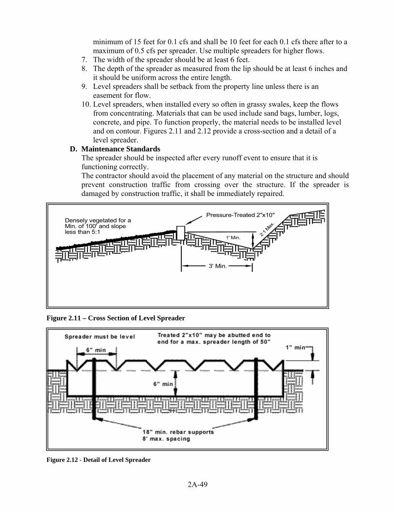
minimum of 15 feet for 0.1 cfs and shall be 10 feet for each 0.1 cfs there after to a maximum of 0.5 cfs per spreader. Use multiple spreaders for higher flows.
7. The width of the spreader should be at least 6 feet. 8. The depth of the spreader as measured from the lip should be at least 6 inches and
it should be uniform across the entire length. 9. Level spreaders shall be setback from the property line unless there is an
easement for flow. 10. Level spreaders, when installed every so often in grassy swales, keep the flows
from concentrating. Materials that can be used include sand bags, lumber, logs, concrete, and pipe. To function properly, the material needs to be installed level and on contour. Figures 2.11 and 2.12 provide a cross-section and a detail of a level spreader.
D. Maintenance Standards The spreader should be inspected after every runoff event to ensure that it is functioning correctly. The contractor should avoid the placement of any material on the structure and should prevent construction traffic from crossing over the structure. If the spreader is damaged by construction traffic, it shall be immediately repaired.
Densely vegetated for aMin. of 100' and slopeless than 5:1
Pressure-Treated 2"x10"
1' Min. 2:1 M
ax.
3' Min.
Figure 2.11 – Cross Section of Level Spreader
Figure 2.12 - Detail of Level Spreader
2A-49
2A-50
BMP C207: Check Dams A. Purpose
Construction of small dams across a swale or ditch reduces the velocity of concentrated flow and dissipates energy at the check dam.
B. Conditions of Use Where temporary channels or permanent channels are not yet vegetated, channel lining is infeasible, and velocity checks are required. 1. Check dams may not be placed in streams unless approved by the State
Department of Fish and Wildlife. Check dams may not be placed in wetlands without approval from a permitting agency.
2. Check dams shall not be placed below the expected backwater from any salmonid bearing water between October 1 and May 31 to ensure that there is no loss of high flow refuge habitat for overwintering juvenile salmonids and emergent salmonid fry.
C. Design and Installation Specifications Whatever material is used, the dam should form a triangle when viewed from the side. This prevents undercutting as water flows over the face of the dam rather than falling directly onto the ditch bottom. Check dams in association with sumps work more effectively at slowing flow and retaining sediment than just a check dam alone. A deep sump should be provided immediately upstream of the check dam. 1. In some cases, if carefully located and designed, check dams can remain as
permanent installations with very minor regrading. They may be left as either spillways, in which case accumulated sediment would be graded and seeded, or as check dams to prevent further sediment from leaving the site.
2. Check dams can be constructed of either rock or pea-gravel filled bags. Numerous new products are also available for this purpose. They tend to be re-usable, quick and easy to install, effective, and cost efficient.
3. Check dams should be placed perpendicular to the flow of water. 4. The maximum spacing between the dams shall be such that the toe of the
upstream dam is at the same elevation as the top of the downstream dam. 5. Keep the maximum height at 2 feet at the center of the dam. 6. Keep the center of the check dam at least 12 inches lower than the outer edges at
natural ground elevation. 7. Keep the side slopes of the check dam at 2:1 or flatter. 8. Key the stone into the ditch banks and extend it beyond the abutments a minimum
of 18 inches to avoid washouts from overflow around the dam. 9. Use filter fabric foundation under a rock or sand bag check dam. If a blanket ditch
liner is used, this is not necessary. A piece of organic or synthetic blanket cut to fit will also work for this purpose.
10. Rock check dams shall be constructed of appropriately sized rock. 11. The rock must be placed by hand or by mechanical means (no dumping of rock to
form dam) to achieve complete coverage of the ditch or swale and to ensure that the center of the dam is lower than the edges. The rock used must be large enough to stay in place given the expected design flow through the channel.
12. In the case of grass-lined ditches and swales, all check dams and accumulated sediment shall be removed when the grass has matured sufficiently to protect the ditch or swale - unless the slope of the swale is greater than 4 percent. The area beneath the check dams shall be seeded and mulched immediately after dam removal.

2A-51
13. Ensure that channel appurtenances, such as culvert entrances below check dams, are not subject to damage or blockage from displaced stones. Figure 2.13 depicts a typical rock check dam.
D. Maintenance Standards Check dams shall be monitored for performance and sediment accumulation during and after each runoff producing rainfall. Sediment shall be removed when it reaches one half the sump depth. 1. Anticipate submergence and deposition above the check dam and erosion from
high flows around the edges of the dam. 2. If significant erosion occurs between dams, install a protective riprap liner in that
portion of the channel.

2A-52

2A-53
Figure 2.13 – Check Dams
BMP C208: Triangular Silt Dike (Geotextile-Encased Check Dam) A. Purpose
Triangular silt dikes may be used as check dams, for perimeter protection, for temporary soil stockpile protection, for drop inlet protection, or as a temporary interceptor dike.
B. Conditions of Use 1. May be used in place of straw bales for temporary check dams in ditches of any
dimension. 2. May be used on soil or pavement with adhesive or staples. 3. TSDs have been used to build temporary:
a. sediment ponds; b. diversion ditches; c. concrete wash out facilities; d. curbing; e. water bars; f. level spreaders; and, g. berms.
C. Design and Installation Specifications Made of urethane foam sewn into a woven geosynthetic fabric. It is triangular, 10 inches to 14 inches high in the center, with a 20-inch to 28-inch base. A 2–foot apron extends beyond both sides of the triangle along its standard section of 7 feet. A sleeve at one end allows attachment of additional sections as needed. 1. Install with ends curved up to prevent water from flowing around the ends. 2. The fabric flaps and check dam units are attached to the ground with wire staples.
Wire staples should be No. 11 gauge wire and should be 200 mm to 300 mm in length.
3. When multiple units are installed, the sleeve of fabric at the end of the unit shall overlap the abutting unit and be stapled.
4. Check dams should be located and installed as soon as construction will allow. 5. Check dams should be placed perpendicular to the flow of water. 6. When used as check dams, the leading edge must be secured with rocks,
sandbags, or a small key slot and staples. 7. In the case of grass-lined ditches and swales, check dams and accumulated
sediment shall be removed when the grass has matured sufficiently to protect the ditch or swale unless the slope of the swale is greater than 4 percent. The area beneath the check dams shall be seeded and mulched immediately after dam removal.
D. Maintenance Standards 1. Triangular silt dams shall be monitored for performance and sediment
accumulation during and after each runoff producing rainfall. Sediment shall be removed when it reaches one half the height of the dam.
2. Anticipate submergence and deposition above the triangular silt dam and erosion from high flows around the edges of the dam. Immediately repair any damage or any undercutting of the dam.
2A-54

BMP C209: Outlet Protection A. Purpose
Outlet protection prevents scour at conveyance outlets and minimizes the potential for downstream erosion by reducing the velocity of concentrated stormwater flows.
B. Conditions of Use Outlet protection is required at the outlets of all ponds, pipes, ditches, or other conveyances, and where runoff is conveyed to a natural or manmade drainage feature such as a stream, wetland, lake, or ditch.
C. Design and Installation Specifications The receiving channel at the outlet of a culvert shall be protected from erosion by rock lining a minimum of 6 feet downstream and extending up the channel sides a minimum of 1–foot above the maximum tailwater elevation or 1-foot above the crown, whichever is higher. For large pipes (more than 18 inches in diameter), the outlet protection lining of the channel is lengthened to four times the diameter of the culvert. 1. Standard wingwalls, and tapered outlets and paved channels should also be
considered when appropriate for permanent culvert outlet protection. (See WSDOT Hydraulic Manual, available through WSDOT Engineering Publications).
2. Organic or synthetic erosion blankets, with or without vegetation, are usually more effective than rock, cheaper, and easier to install. Materials can be chosen using manufacturer product specifications. ASTM test results are available for most products and the designer can choose the correct material for the expected flow.
3. With low flows, vegetation (including sod) can be effective. 4. The following guidelines shall be used for riprap outlet protection:
a. If the discharge velocity at the outlet is less than 5 fps (pipe slope less than 1 percent), use 2-inch to 8-inch riprap. Minimum thickness is 1-foot.
b. For 5 to 10 fps discharge velocity at the outlet (pipe slope less than 3 percent), use 24-inch to 4-foot riprap. Minimum thickness is 2 feet.
c. For outlets at the base of steep slope pipes (pipe slope greater than 10 percent), an engineered energy dissipater shall be used.
5. Filter fabric or erosion control blankets should always be used under riprap to prevent scour and channel erosion.
6. New pipe outfalls can provide an opportunity for low-cost fish habitat improvements. For example, an alcove of low-velocity water can be created by constructing the pipe outfall and associated energy dissipater back from the stream edge and digging a channel, over widened to the upstream side, from the outfall. Overwintering juvenile and migrating adult salmonids may use the alcove as shelter during high flows. Bank stabilization, bioengineering, and habitat features may be required for disturbed areas. See Volume V for more information on outfall system design.
D. Maintenance Standards 1. Inspect and repair as needed. 2. Add rock as needed to maintain the intended function. 3. Clean energy dissipater if sediment builds up.
2A-55
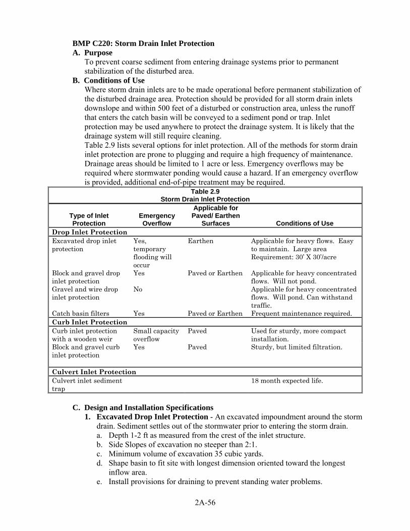
BMP C220: Storm Drain Inlet Protection A. Purpose
To prevent coarse sediment from entering drainage systems prior to permanent stabilization of the disturbed area.
B. Conditions of Use Where storm drain inlets are to be made operational before permanent stabilization of the disturbed drainage area. Protection should be provided for all storm drain inlets downslope and within 500 feet of a disturbed or construction area, unless the runoff that enters the catch basin will be conveyed to a sediment pond or trap. Inlet protection may be used anywhere to protect the drainage system. It is likely that the drainage system will still require cleaning. Table 2.9 lists several options for inlet protection. All of the methods for storm drain inlet protection are prone to plugging and require a high frequency of maintenance. Drainage areas should be limited to 1 acre or less. Emergency overflows may be required where stormwater ponding would cause a hazard. If an emergency overflow is provided, additional end-of-pipe treatment may be required.
Table 2.9 Storm Drain Inlet Protection
Type of Inlet Protection
Emergency Overflow
Applicable for Paved/ Earthen
Surfaces Conditions of Use Drop Inlet Protection Excavated drop inlet protection
Yes, temporary flooding will occur
Earthen Applicable for heavy flows. Easy to maintain. Large area Requirement: 30’ X 30’/acre
Block and gravel drop inlet protection
Yes Paved or Earthen Applicable for heavy concentrated flows. Will not pond.
Gravel and wire drop inlet protection
No Applicable for heavy concentrated flows. Will pond. Can withstand traffic.
Catch basin filters Yes Paved or Earthen Frequent maintenance required. Curb Inlet Protection Curb inlet protection with a wooden weir
Small capacity overflow
Paved Used for sturdy, more compact installation.
Block and gravel curb inlet protection
Yes Paved Sturdy, but limited filtration.
Culvert Inlet Protection Culvert inlet sediment trap
18 month expected life.
C. Design and Installation Specifications
1. Excavated Drop Inlet Protection - An excavated impoundment around the storm drain. Sediment settles out of the stormwater prior to entering the storm drain. a. Depth 1-2 ft as measured from the crest of the inlet structure. b. Side Slopes of excavation no steeper than 2:1. c. Minimum volume of excavation 35 cubic yards. d. Shape basin to fit site with longest dimension oriented toward the longest
inflow area. e. Install provisions for draining to prevent standing water problems.
2A-56
f. Clear the area of all debris. g. Grade the approach to the inlet uniformly. h. Drill weep holes into the side of the inlet. i. Protect weep holes with screen wire and washed aggregate. j. Seal weep holes when removing structure and stabilizing area. k. It may be necessary to build a temporary dike to the down slope side
of the structure to prevent bypass flow. 2 Block and Gravel Filter - A barrier formed around the storm drain inlet with
standard concrete blocks and gravel. See Figure 2.14. a. Height 1 to 2 feet above inlet. b. Recess the first row 2 inches into the ground for stability. c. Support subsequent courses by placing a 2x4 through the block opening. d. Do not use mortar. e. Lay some blocks in the bottom row on their side for dewatering the pool. f. Place hardware cloth or comparable wire mesh with ½-inch openings over all
block openings. g. Place gravel just below the top of blocks on slopes of 2:1 or flatter. h. An alternative design is a gravel donut. i. Inlet slope of 3:1. j. Outlet slope of 2:1. k. 1-foot wide level stone area between the structure and the inlet. l. Inlet slope stones 3 inches in diameter or larger. m. Outlet slope use gravel ½- to ¾-inch at a minimum thickness of 1-foot.
2A-57

Figure 2.14 – Block and Gravel Filter
3. Gravel and Wire Mesh Filter - A gravel barrier placed over the top of the inlet. This structure does not provide an overflow. a. Hardware cloth or comparable wire mesh with ½-inch openings. b. Coarse aggregate. c. Height 1-foot or more, 18 inches wider than inlet on all sides. d. Place wire mesh over the drop inlet so that the wire extends a minimum of 1-
foot beyond each side of the inlet structure. e. If more than one strip of mesh is necessary, overlap the strips. f. Place coarse aggregate over the wire mesh. g. The depth of the gravel should be at least 12 inches over the entire inlet
opening and extend at least 18 inches on all sides. 4. Catch basin Filters - Inserts should be designed by the manufacturer for use at
construction sites. The limited sediment storage capacity increases the amount of inspection and maintenance required, which may be daily for heavy sediment loads. The maintenance requirements can be reduced by combining a catch basin
2A-58

filter with another type of inlet protection. This type of inlet protection provides flow bypass without overflow and therefore may be a better method for inlets located along active rights-of-way. a. 5 cubic feet of storage. b. Dewatering provisions. c. High-flow bypass that will not clog under normal use at a construction site. d. The catch basin filter is inserted in the catch basin just below the grating.
5. Curb Inlet Protection with Wooden Weir – Barrier formed around a curb inlet with a wooden frame and gravel. a. Wire mesh with ½-inch openings. b. Extra strength filter cloth. c. Construct a frame. d. Attach the wire and filter fabric to the frame. e. Pile coarse washed aggregate against wire/fabric. f. Place weight on frame anchors.
6. Block and Gravel Curb Inlet Protection – Barrier formed around an inlet with concrete blocks and gravel. See Figure 2.15. a. Wire mesh with ½-inch openings. b. Place two concrete blocks on their sides abutting the curb at either side of the
inlet opening. These are spacer blocks. c. Place a 2x4 stud through the outer holes of each spacer block to align the front
blocks. d. Place blocks on their sides across the front of the inlet and abutting the spacer
blocks. e. Place wire mesh over the outside vertical face. f. Pile coarse aggregate against the wire to the top of the barrier.
7. Curb and Gutter Sediment Barrier – Sandbag or rock berm (riprap and aggregate) 3 feet high and 3 feet wide in a horseshoe shape. See Figure 2.16. a. Construct a horseshoe shaped berm, faced with coarse aggregate if using
riprap, 3 feet high and 3 feet wide, at least 2 feet from the inlet. b. Construct a horseshoe shaped sedimentation trap on the outside of the berm
sized to sediment trap standards for protecting a culvert inlet. D. Maintenance Standards
1. Catch basin filters should be inspected frequently, especially after storm events. If the insert becomes clogged, it should be cleaned or replaced.
2. For systems using stone filters: If the stone filter becomes clogged with sediment, the stones must be pulled away from the inlet and cleaned or replaced. Since cleaning of gravel at a construction site may be difficult, an alternative approach would be to use the clogged stone as fill and put fresh stone around the inlet.
3. Do not wash sediment into storm drains while cleaning. Spread all excavated material evenly over the surrounding land area or stockpile and stabilize as appropriate.
2A-59

Figure 2.15 – Block and Gravel Curb Inlet Protection
A
Plan View
Back of Sidewalk
Wire Screen orFilter Fabric
Catch Basin
Curb Inlet
Concrete BlockPonding Height
Overflow
2x4 Wood Stud(100x50 Timber Stud)
Concrete BlockWire Screen orFilter Fabric
Curb Inlet
¾" Drain Gravel(20mm)
¾" Drain Gravel(20mm)Section A - A
Back of Curb Concrete Block
2x4 Wood Stud
Catch Basin
NOTES:1. Use block and gravel type sediment barrier when curb inlet is located in gently sloping street segment, where water can pond and allow sediment to separate from runoff.2. Barrier shall allow for overflow from severe storm event.3. Inspect barriers and remove sediment after each storm event. Sediment and gravel must be removed from the traveled way immediately.
2A-60

Figure 2.16 – Curb and Gutter Barrier
BMP C231: Brush Barrier A. Purpose
The purpose of brush barriers is to reduce the transport of coarse sediment from a construction site by providing a temporary physical barrier to sediment and reducing the runoff velocities of overland flow.
B. Conditions of Use 1. Brush barriers may be used downslope of all disturbed areas of less than one-
quarter acre. 2. Brush barriers are not intended to treat concentrated flows, nor are they intended
to treat substantial amounts of overland flow. Any concentrated flows must be
2A-61

2A-62
conveyed through the drainage system to a sediment pond. The only circumstance in which overland flow can be treated solely by a barrier, rather than by a sediment pond, is when the area draining to the barrier is small.
3. Brush barriers should only be installed on contours. C. Design and Installation Specifications
1. Height 2 feet (minimum) to 5 feet (maximum). 2. Width 5 feet at base (minimum) to 15 feet (maximum). 3. Filter fabric (geotextile) may be anchored over the brush berm to enhance the
filtration ability of the barrier. Ten-ounce burlap is an adequate alternative to filter fabric.
4. Chipped site vegetation, composted mulch, or wood-based mulch (hog fuel) can be used to construct brush barriers.
5. A 100 percent biodegradable installation can be constructed using 10-ounce burlap held in place by wooden stakes. Figure 2.18 depicts a typical brush barrier.
D. Maintenance Standards 1. There shall be no signs of erosion or concentrated runoff under or around the
barrier. If concentrated flows are bypassing the barrier, it must be expanded or augmented by toed-in filter fabric.
2. The dimensions of the barrier must be maintained.
If required, drape filter fabricover brush and secure in 4"x4"min. trench with compactedbackfill.
Min. 5' wide brush barrier withmax. 6" diameter woody debris.Alternatively topsoil strippingsmay be used to form the barrier.
Anchor downhill edge offilter fabric with stakes,sandbags, or equivalent.
2' Min. Height
Figure 2.18 – Brush Barrier
BMP C232: Gravel Filter Berm A. Purpose
A gravel filter berm is constructed on rights-of-way or traffic areas within a construction site to retain sediment by using a filter berm of gravel or crushed rock.
B. Conditions of Use Where a temporary measure is needed to retain sediment from rights-of-way or in traffic areas on construction sites.
C. Design and Installation Specifications 1. Berm material shall be ¾ to 3 inches in size, washed well-grade gravel or crushed
rock with less than 5 percent fines.

2. Spacing of berms: a. Every 300 feet on slopes less than 5 percent b. Every 200 feet on slopes between 5 percent and 10 percent c. Every 100 feet on slopes greater than 10 percent
3. Berm dimensions: a. 1 foot high with 3:1 side slopes b. 8 linear feet per 1 cfs runoff based on the 10-year, 24-hour design storm
D. Maintenance Standards Regular inspection is required. Sediment shall be removed and filter material replaced as needed.
BMP C233: Silt Fence A. Purpose
Use of a silt fence reduces the transport of coarse sediment from a construction site by providing a temporary physical barrier to sediment and reducing the runoff velocities of overland flow. See Figure 2.19 for details on silt fence construction.
B. Conditions of Use 1. Silt fence may be used downslope of all disturbed areas. 2. Silt fence is not intended to treat concentrated flows, nor is it intended to treat
substantial amounts of overland flow. Any concentrated flows must be conveyed through the drainage system to a sediment pond. The only circumstance in which overland flow can be treated solely by a silt fence, rather than by a sediment pond, is when the area draining to the fence is one acre or less and flow rates are less than 0.5 cfs.
3. Silt fences should not be constructed in streams or used in V-shaped ditches. They are not an adequate method of silt control for anything deeper than sheet or overland flow.
Figure 2.19 – Silt Fence
2A-63
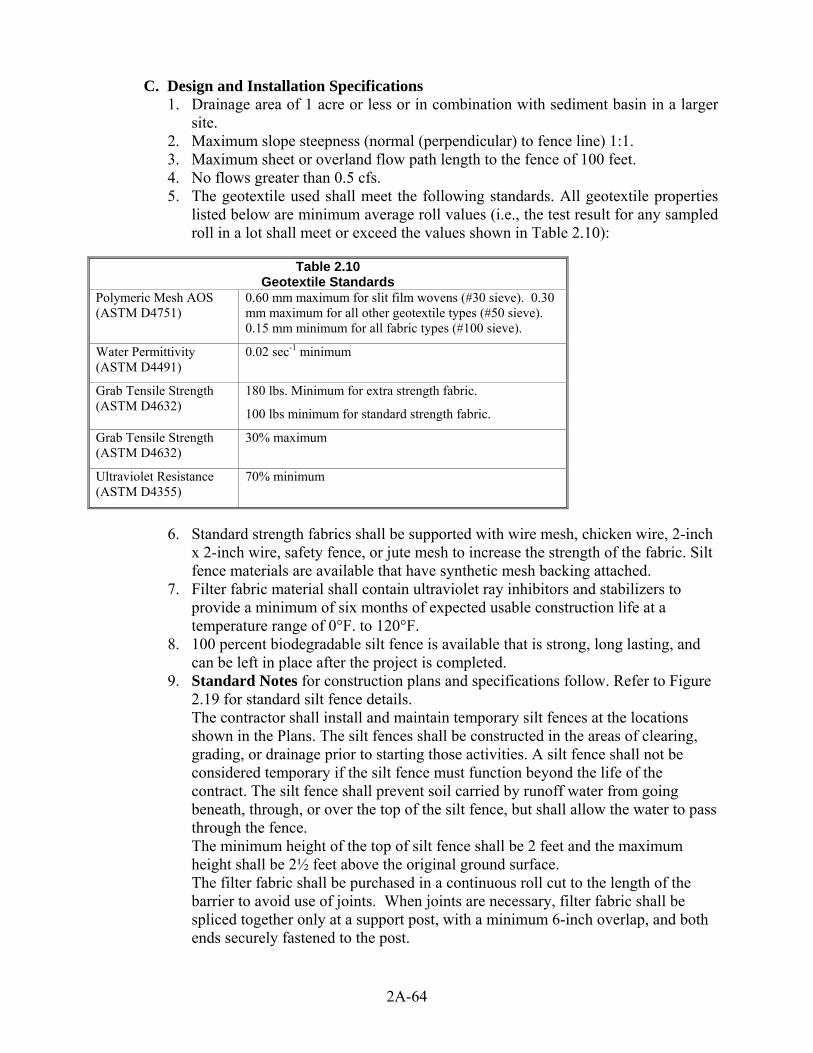
C. Design and Installation Specifications 1. Drainage area of 1 acre or less or in combination with sediment basin in a larger
site. 2. Maximum slope steepness (normal (perpendicular) to fence line) 1:1. 3. Maximum sheet or overland flow path length to the fence of 100 feet. 4. No flows greater than 0.5 cfs. 5. The geotextile used shall meet the following standards. All geotextile properties
listed below are minimum average roll values (i.e., the test result for any sampled roll in a lot shall meet or exceed the values shown in Table 2.10):
Table 2.10
Geotextile Standards Polymeric Mesh AOS (ASTM D4751)
0.60 mm maximum for slit film wovens (#30 sieve). 0.30 mm maximum for all other geotextile types (#50 sieve). 0.15 mm minimum for all fabric types (#100 sieve).
Water Permittivity (ASTM D4491)
0.02 sec-1 minimum
Grab Tensile Strength (ASTM D4632)
180 lbs. Minimum for extra strength fabric.
100 lbs minimum for standard strength fabric.
Grab Tensile Strength (ASTM D4632)
30% maximum
Ultraviolet Resistance (ASTM D4355)
70% minimum
6. Standard strength fabrics shall be supported with wire mesh, chicken wire, 2-inch
x 2-inch wire, safety fence, or jute mesh to increase the strength of the fabric. Silt fence materials are available that have synthetic mesh backing attached.
7. Filter fabric material shall contain ultraviolet ray inhibitors and stabilizers to provide a minimum of six months of expected usable construction life at a temperature range of 0°F. to 120°F.
8. 100 percent biodegradable silt fence is available that is strong, long lasting, and can be left in place after the project is completed.
9. Standard Notes for construction plans and specifications follow. Refer to Figure 2.19 for standard silt fence details. The contractor shall install and maintain temporary silt fences at the locations shown in the Plans. The silt fences shall be constructed in the areas of clearing, grading, or drainage prior to starting those activities. A silt fence shall not be considered temporary if the silt fence must function beyond the life of the contract. The silt fence shall prevent soil carried by runoff water from going beneath, through, or over the top of the silt fence, but shall allow the water to pass through the fence. The minimum height of the top of silt fence shall be 2 feet and the maximum height shall be 2½ feet above the original ground surface. The filter fabric shall be purchased in a continuous roll cut to the length of the barrier to avoid use of joints. When joints are necessary, filter fabric shall be spliced together only at a support post, with a minimum 6-inch overlap, and both ends securely fastened to the post.
2A-64

The geotextile shall be attached on the up-slope side of the posts and support system with staples, wire, or in accordance with the manufacturer's recommendations. The geotextile shall be attached to the posts in a manner that reduces the potential for geotextile tearing at the staples, wire, or other connection device. Silt fence back-up support for the geotextile in the form of a wire or plastic mesh is dependent on the properties of the geotextile selected for use. If wire or plastic back-up mesh is used, the mesh shall be fastened securely to the up-slope of the posts with the geotextile being up-slope of the mesh back-up support. The geotextile at the bottom of the fence shall be buried in a trench to a minimum depth of 12 inches below the ground surface. The trench shall be backfilled with 3/4-inch minimum diameter washed gravel, or native material, where suitable, and the soil tamped in place over the buried portion of the geotextile, such that no flow can pass beneath the fence and scouring can not occur. When wire or polymeric back-up support mesh is used, the wire or polymeric mesh shall extend into the trench a minimum of 3 inches. The fence posts shall be placed or driven a minimum of 18 inches. A minimum depth of 12 inches is allowed if topsoil or other soft subgrade soil is not present and a minimum depth of 18 inches cannot be reached. Fence post depths shall be increased by 6 inches if the fence is located on slopes of 3:1 or steeper and the slope is perpendicular to the fence. If required post depths cannot be obtained, the posts shall be adequately secured by bracing or guying to prevent overturning of the fence due to sediment loading. Silt fences shall be located on contour as much as possible, except at the ends of the fence, where the fence shall be turned uphill such that the silt fence captures the runoff water and prevents water from flowing around the end of the fence. If the fence must cross contours, with the exception of the ends of the fence, gravel check dams placed perpendicular to the back of the fence shall be used to minimize concentrated flow and erosion along the back of the fence. The gravel check dams shall be approximately 1-foot deep at the back of the fence. It shall be continued perpendicular to the fence at the same elevation until the top of the check dam intercepts the ground surface behind the fence. The gravel check dams shall consist of crushed surfacing base course, gravel backfill for walls, or shoulder ballast. The gravel check dams shall be located every 10 feet along the fence where the fence must cross contours. The slope of the fence line where contours must be crossed shall not be steeper than 3:1. Wood, steel or equivalent posts shall be used. Wood posts shall have minimum dimensions of 2 inches by 2 inches by 3 feet minimum length, and shall be free of defects such as knots, splits, or gouges. Steel posts shall consist of either size No. 6 rebar or larger, ASTM A 120 steel pipe with a minimum diameter of 1-inch, U, T, L, or C shape steel posts with a minimum weight of 1.35 lbs./ft. or other steel posts having equivalent strength and bending resistance to the post sizes listed. The spacing of the support posts shall be a maximum of 6 feet. Fence back-up support, if used, shall consist of steel wire with a maximum mesh spacing of 2 inches, or a prefabricated polymeric mesh. The strength of the wire or polymeric mesh shall be equivalent to or greater than 180 lbs. grab tensile
2A-65

strength. The polymeric mesh must be as resistant to ultraviolet radiation as the geotextile it supports. Filter fabric shall not be stapled to existing trees. Silt Fence Installation by Slicing Method Silt fence installation using the slicing method specification details follow. Refer to Figure 2.20 for slicing method details. The base of both end posts must be at least 2 to 4 inches above the top of the silt fence fabric on the middle posts for ditch checks to drain properly. Use a hand level or string level, if necessary, to mark base points before installation. Install posts 3 to 4 feet apart in critical retention areas and 6 to 7 feet apart in standard applications. Install posts 24 inches deep on the downstream side of the silt fence, and as close as possible to the fabric, enabling posts to support the fabric from upstream water pressure. Install posts with the nipples facing away from the silt fence fabric. Attach the fabric to each post with three ties, all spaced within the top 8 inches of the fabric. Attach each tie diagonally 45 degrees through the fabric, with each puncture at least 1 inch vertically apart. In addition, each tie should be positioned to hang on a post nipple when tightening to prevent sagging. Wrap approximately 6 inches of fabric around the end posts and secure with 3 ties.
10. No more than 24 inches of a 36-inch fabric is allowed above ground level. 11. The rope lock system must be used in all ditch check applications. 12. The installation should be checked and corrected for any deviation before
compaction. Use a flat-bladed shovel to tuck fabric deeper into the ground if necessary.
13. Compaction is vitally important for effective results. Compact the soil immediately next to the silt fence fabric with the front wheel of the tractor, skid steer, or roller exerting at least 60 pounds per square inch.
14. Compact the upstream side first and then each side twice for a total of four trips. D. Maintenance Standards
1. Silt fences shall be inspected immediately after each rainfall event and at least daily during prolonged rainfall. Any damage shall be repaired immediately.
2. If concentrated flows are evident uphill of the fence, they must be intercepted and conveyed to a sediment pond.
3. It is important to check the uphill side of the fence for signs of the fence clogging and acting as a barrier to flow and then causing channelization of flows parallel to the fence. If this occurs, replace the fence or remove the trapped sediment.
4. Sediment deposits shall either be removed when the deposit reaches approximately one-third the height of the silt fence, or a second silt fence shall be installed.
5. If the filter fabric (geotextile) has deteriorated due to ultraviolet breakdown, it shall be replaced.
2A-66

Figure 2.20 – Silt Fence Installation by Slicing Method
BMP C234: Vegetated Strip A. Purpose
Vegetated strips reduce the transport of coarse sediment from a construction site by providing a temporary physical barrier to sediment and reducing the runoff velocities of overland flow.
B. Conditions of Use 1. Vegetated strips may be used downslope of all disturbed areas. 2. Vegetated strips are not intended to treat concentrated flows, nor are they
intended to treat substantial amounts of overland flow. Any concentrated flows must be conveyed through the drainage system to a sediment pond. The only circumstance in which overland flow can be treated solely by a strip, rather than by a sediment pond, is when the following criteria are met (see Table 2.11):
2A-67

Table 2.11 Vegetated Strips
Average Slope Slope Percent Flowpath Length 1.5H:1V or less 67% or less 100 feet 2H:1V or less 50% or less 115 feet 4H:1V or less 25% or less 150 feet 6H:1V or less 16.7% or less 200 feet 10H:1V or less 10% or less 250 feet
C. Design and Installation Specifications 1. The vegetated strip shall consist of a minimum of a 25-foot wide continuous strip
of dense vegetation with a permeable topsoil. Grass covered, landscaped areas are generally not adequate because the volume of sediment overwhelms the grass. Ideally, vegetated strips shall consist of undisturbed native growth with a well-developed soil that allows for infiltration of runoff.
2. The slope within the strip shall not exceed 4H:1V. 3. The uphill boundary of the vegetated strip shall be delineated with clearing limits.
D. Maintenance Standards 1 Any areas damaged by erosion or construction activity shall be seeded
immediately and protected by mulch. 2 If more than 5 feet of the original vegetated strip width has had vegetation
removed or is being eroded, sod must be installed. 3 If there are indications that concentrated flows are traveling across the buffer,
surface water controls must be installed to reduce the flows entering the buffer, or additional perimeter protection must be installed.
BMP C235: Straw Wattles A. Purpose
Straw wattles are temporary erosion and sediment control barriers consisting of straw that is wrapped in biodegradable tubular plastic or similar encasing material. They reduce the velocity and can spread the flow of rill and sheet runoff, and can capture and retain sediment. Straw wattles are typically 8 to 10 inches in diameter and 25 to 30 feet in length. The wattles are placed in shallow trenches and staked along the contour of disturbed or newly constructed slopes. See Figure 2.21 for typical construction details.
B. Conditions of Use 1. Disturbed areas that require immediate erosion protection. 2. Exposed soils during the period of short construction delays, or over winter
months. 3. On slopes requiring stabilization until permanent vegetation can be established. 4. Straw wattles are effective for one to two seasons. 5. If conditions are appropriate, wattles can be staked to the ground using willow
cuttings for added revegetation. 6. Rilling can occur beneath wattles if not properly entrenched and water can pass
between wattles if not tightly abutted together. C. Design Criteria
1. It is critical that wattles are installed perpendicular to the flow direction and parallel to the slope contour.
2. Narrow trenches should be dug across the slope on contour to a depth of 3 to 5 inches on clay soils and soils with gradual slopes. On loose soils, steep slopes,
2A-68

and areas with high rainfall, the trenches should be dug to a depth of 5 to 7 inches, or 1/2 to 2/3 of the thickness of the wattle.
3. Start building trenches and installing wattles from the base of the slope and work up. Excavated material should be spread evenly along the uphill slope and compacted using hand tamping or other methods.
4. Construct trenches at contour intervals of 3 to 30 feet apart depending on the steepness of the slope, soil type, and rainfall. The steeper the slope, the closer together the trenches.
5. Install the wattles snugly into the trenches and abut tightly end to end. Do not overlap the ends.
6. Install stakes at each end of the wattle, and at 4-foot centers along entire length of wattle.
7. If required, install pilot holes for the stakes using a straight bar to drive holes through the wattle and into the soil.
8. At a minimum, wooden stakes should be approximately 3/4 x 3/4 x 24 inches. Willow cuttings or 3/8-inch rebar can also be used for stakes.
D. Maintenance Standards 1. Stakes should be driven through the middle of the wattle, leaving 2 to 3 inches of
the stake protruding above the wattle. 2. Wattles may require maintenance to ensure they are in contact with soil and
thoroughly entrenched, especially after significant rainfall on steep sandy soils. 3. Inspect the slope after significant storms and repair any areas where wattles are
not tightly abutted or water has scoured beneath the wattles.
2A-69

Figure 2.21 – Straw Wattles
BMP C240: Sediment Trap A. Purpose
A sediment trap is a small temporary ponding area with a gravel outlet used to collect and store sediment from sites cleared and/or graded during construction. Sediment traps, along with other perimeter controls, shall be installed before any land disturbance takes place in the drainage area.
B. Conditions of Use Prior to leaving a construction site, stormwater runoff must pass through a sediment pond or trap or other appropriate sediment removal best management practice. Non-engineered sediment traps may be used on-site prior to an engineered sediment trap or sediment pond to provide additional sediment removal capacity. It is intended for use on sites where the tributary drainage area is less than 3 acres, with no unusual
2A-70

drainage features, and a projected build-out time of six months or less. The sediment trap is a temporary measure (with a design life of approximately 6 months) and shall be maintained until the site area is permanently protected against erosion by vegetation and/or structures. Sediment traps and ponds are only effective in removing sediment down to about the medium silt size fraction. Runoff with sediment of finer grades (fine silt and clay) will pass through untreated, emphasizing the need to control erosion to the maximum extent first. Whenever possible, sediment-laden water shall be discharged into onsite, relatively level, vegetated areas (see BMP C234 – Vegetated Strip). This is the only way to effectively remove fine particles from runoff unless chemical treatment or filtration is used. This can be particularly useful after initial treatment in a sediment trap or pond. The areas of release must be evaluated on a site-by-site basis in order to determine appropriate locations for and methods of releasing runoff. Vegetated wetlands shall not be used for this purpose. Frequently, it may be possible to pump water from the collection point at the downhill end of the site to an upslope vegetated area. Pumping shall only augment the treatment system, not replace it, because of the possibility of pump failure or runoff volume in excess of pump capacity. All projects that are constructing permanent facilities for runoff quantity control should use the rough-graded or final-graded permanent facilities for traps and ponds. This includes combined facilities and infiltration facilities. When permanent facilities are used as temporary sedimentation facilities, the surface area requirement of a sediment trap or pond must be met. If the surface area requirements are larger than the surface area of the permanent facility, then the trap or pond shall be enlarged to comply with the surface area requirement. The permanent pond shall also be divided into two cells as required for sediment ponds. Either a permanent control structure or the temporary control structure (described in BMP C241, Temporary Sediment Pond) can be used. If a permanent control structure is used, it may be advisable to partially restrict the lower orifice with gravel to increase residence time while still allowing dewatering of the pond. A shut-off valve may be added to the control structure to allow complete retention of stormwater in emergency situations. In this case, an emergency overflow weir must be added.
C. Design and Installation Specifications 1. See Figures 2.22 and 2.23 for details. 2. If permanent runoff control facilities are part of the project, they should be used
for sediment retention. 3. To determine the sediment trap geometry, first calculate the design surface area
(SA) of the trap, measured at the invert of the weir. Use the following equation: SA = FS(Q2/Vs) Where Q2 = Design inflow based on the peak discharge from the developed 2-year runoff
event from the contributing drainage area as computed in the hydrologic analysis. The 10-year peak flow shall be used if the project size, expected timing and duration of construction, or downstream conditions warrant a higher level of protection. If no hydrologic analysis is required, the Rational Method may be used.
Vs = The settling velocity of the soil particle of interest. The 0.02 mm (medium silt) particle with an assumed density of 2.65 g/cm3 has been selected as the particle of interest and has a settling velocity (Vs) of 0.00096 ft/sec.
2A-71

FS = A safety factor of 2 to account for non-ideal settling. Therefore, the equation for computing surface area becomes: SA = 2 x Q2/0.00096 or 2080 square feet per cfs of inflow
Note: Even if permanent facilities are used, they must still have a surface area that is at least as large as that derived from the above formula. If they do not, the pond must be enlarged.
4. To aid in determining sediment depth, all sediment traps shall have a staff gauge with a prominent mark 1-foot above the bottom of the trap.
5. Sediment traps may not be feasible on utility projects due to the limited work space or the short-term nature of the work. Portable tanks may be used in place of sediment traps for utility projects.
D. Maintenance Standards 1. Sediment shall be removed from the trap when it reaches 1-foot in depth. 2. Any damage to the pond embankments or slopes shall be repaired.
Surface area determined
at top of weir
Note: Trap may be formed by berm or bypartial or complete excavation
Discharge to stabilizedconveyance, outlet, orlevel spreader
¾" - 1.5"Washed gravel
Geotextile
Flat Bottom
1' Min. Overflow
1' Min.
4' Min.
RipRap2"-4" Rock
1' Min.
1.5' Min.3.5'-5'
3H:1V Max.
Figure 2.22 Cross Section of Sediment Trap
Figure 2.23 Sediment Trap Outlet
Native soil orcompacted backfill
Geotextile
Min. 1' depth2"-4"' rock
Min. 1' depth 3/4"-1.5"washed gravel
6' Min.1' Min. depth overflow spillway
BMP C241: Temporary Sediment Pond A. Purpose
Sediment ponds remove sediment from runoff originating from disturbed areas of the site. Sediment ponds are typically designed to remove sediment no smaller than medium silt (0.02 mm). Consequently, they usually reduce turbidity only slightly.
2A-72

B. Conditions of Use Prior to leaving a construction site, stormwater runoff must pass through a sediment pond or other appropriate sediment removal best management practice. A sediment pond shall be used where the contributing drainage area is 3 acres or more. Ponds must be used in conjunction with erosion control practices to reduce the amount of sediment flowing into the basin.
C. Design and Installation Specifications 1. Sediment basins must be installed only on sites where failure of the structure
would not result in loss of life, damage to homes or buildings, or interruption of use or service of public roads or utilities. Also, sediment traps and ponds are attractive to children and can be very dangerous. Compliance with local ordinances regarding health and safety must be addressed. If fencing of the pond is required, the type of fence and its location shall be shown on the ESC plan.
2. Structures having a maximum storage capacity at the top of the dam of 10 acre-ft (435,600 ft3) or more are subject to the Washington Dam Safety Regulations (Chapter 173-175 WAC).
3. See Figure 2.24, Figure 2.25, and Figure 2.26 for details. 4. If permanent runoff control facilities are part of the project, they should be used
for sediment retention. The surface area requirements of the sediment basin must be met. This may require enlarging the permanent basin to comply with the surface area requirements. If a permanent control structure is used, it may be advisable to partially restrict the lower orifice with gravel to increase residence time while still allowing dewatering of the basin.
5. Use of infiltration facilities for sedimentation basins during construction tends to clog the soils and reduce their capacity to infiltrate. Use of infiltration facilities for temporary sediment retention will not normally be allowed, and will be reviewed on a case by case basis. If infiltration facilities are approved for temporary sediment storage, the sides and bottom of the facility must only be rough excavated to a minimum of 2 feet above final grade. Final grading of the infiltration facility shall occur only when all contributing drainage areas are fully stabilized. The infiltration pretreatment facility should be fully constructed and used with the sedimentation basin to help prevent clogging.
6. Determining Pond Geometry: Obtain the discharge from the hydrologic calculations of the peak flow for the 2-year runoff event (Q2). The 10-year peak flow shall be used if the project size, expected timing and duration of construction, or downstream conditions warrant a higher level of protection. If no hydrologic analysis is required, the Rational Method may be used. Determine the required surface area at the top of the riser pipe with the equation: SA = 2 x Q2/0.00096 or 2080 square feet per cfs of inflow
7. See BMP C240 for more information on the derivation of the surface area
calculation. The basic geometry of the pond can now be determined using the following design criteria: a. Required surface area SA (from Step 2 above) at top of riser. b. Minimum 3.5-foot depth from top of riser to bottom of pond. c. Maximum 3:1 interior side slopes and maximum 2:1 exterior slopes. The
interior slopes can be increased to a maximum of 2:1 if fencing is provided at or above the maximum water surface.
2A-73

d. One foot of freeboard between the top of the riser and the crest of the emergency spillway.
e. Flat bottom. f. Minimum 1-foot deep spillway. g. Length-to-width ratio between 3:1 and 6:1.
8. Sizing of Discharge Mechanisms: The outlet for the basin consists of a combination of principal and emergency spillways. These outlets must pass the peak runoff expected from the contributing drainage area for a 100-year storm. If, due to site conditions and basin geometry, a separate emergency spill-way is not feasible, the principal spillway must pass the entire peak runoff expected from the 100-year storm. However, an attempt to provide a separate emergency spillway should always be made. The runoff calculations should be based on the site conditions during construction. The flow through the dewatering orifice cannot be utilized when calculating the 100-year storm elevation because of its potential to become clogged; therefore, available spillway storage must begin at the principal spillway riser crest. The principal spillway designed by the procedures contained in this standard will result in some reduction in the peak rate of runoff. However, the riser outlet design will not adequately control the basin discharge to the predevelopment discharge limitations as stated in Minimum Requirement #7: Flow Control. However, if the basin for a permanent stormwater detention pond is used for a temporary sedimentation basin, the control structure for the permanent pond can be used to maintain predevelopment discharge limitations. The size of the basin, the expected life of the construction project, the anticipated downstream effects and the anticipated weather conditions during construction, should be considered to determine the need of additional discharge control. See Figure 2.27 for riser inflow curves.
Key divider into slopeto prevent flowaround sides
The pond length shall be 3 to 6times the maximum pond width Emergency overflow
spillway
Discharge to stabilizedconveyance, outlet, orlevel spreader
Note: Pond may be formed by berm orby partial or complete excavation
InflowPond length
Silt fence orequivalent divider
Riser pipe
Figure 2.24 – Sediment Pond Plan View
2A-74

Riser pipe(principal spillway)open at top withtrash rackper Fig 4.4.4E
Dewatering device(see riser detail)
Wire-backed silt fencestaked haybales wrappedwith filter fabric, orequivalent divider
Dewateringorifice
Concrete base(see riser detail)
Discharge to stabilizedconveyance outlet orlevel spreader
Embankment compacted 95%pervious materials such asgravel or clean sand shallnot be used
6' min. WidthCrest ofemergency spillway
Figure 2.25 – Sediment Pond Cross Section
Perforated polyethylenedrainage tubing, diametermin. 2" larger thandewatering orifice.Tubing shall comply with ASTM F667 and AASHTO M294
Polyethylene cap Provide adequatestrapping
Dewatering orifice, schedule,40 steel stub min.Diameter as per calculations
Alternatively, metal stakesand wire may be used toprevent flotation
2X riser dia. Min.
Concrete base
Corrugatedmetal riser
Watertightcoupling
18" min.
6" min.
Tack weld
3.5" min.
Figure 2.26 – Sediment Pond Riser Detail
2A-75
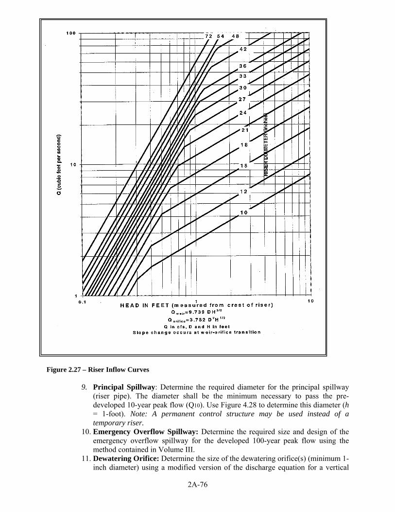
Figure 2.27 – Riser Inflow Curves
9. Principal Spillway: Determine the required diameter for the principal spillway
(riser pipe). The diameter shall be the minimum necessary to pass the pre-developed 10-year peak flow (Q10). Use Figure 4.28 to determine this diameter (h = 1-foot). Note: A permanent control structure may be used instead of a temporary riser.
10. Emergency Overflow Spillway: Determine the required size and design of the emergency overflow spillway for the developed 100-year peak flow using the method contained in Volume III.
11. Dewatering Orifice: Determine the size of the dewatering orifice(s) (minimum 1-inch diameter) using a modified version of the discharge equation for a vertical
2A-76

orifice and a basic equation for the area of a circular orifice. Determine the required area of the orifice with the following equation: 0.5 0.5
0.6x3600 (2 ) Tg A h A s
o = where Ao = orifice area (square feet) As = pond surface area (square feet) h = head of water above orifice (height of riser in feet) T = dewatering time (24 hours) g = acceleration of gravity (32.2 feet/second2) Convert the required surface area to the required diameter D of the orifice: o
o A A D = 24x = 13.54x π The vertical, perforated tubing connected to the dewatering orifice must be at least 2 inches larger in diameter than the orifice to improve flow characteristics. The size and number of perforations in the tubing should be large enough so that the tubing does not restrict flow. The orifice should control the flow rate.
12. Additional Design Specifications:
a. The pond shall be divided into two roughly equal volume cells by a permeable divider that will reduce turbulence while allowing movement of water between cells. The divider shall be at least one-half the height of the riser and a minimum of one foot below the top of the riser. Wire-backed, 2- to 3-foot high, extra strength filter fabric supported by treated 4"x4"s can be used as a divider. Alternatively, staked straw bales wrapped with filter fabric (geotextile) may be used.
b. If the pond is more than 6 feet deep, a different mechanism must be proposed. A riprap embankment is one acceptable method of separation for deeper ponds. Other designs that satisfy the intent of this provision are allowed as long as the divider is permeable, structurally sound, and designed to prevent erosion under or around the barrier. To aid in determining sediment depth, one-foot intervals shall be prominently marked on the riser. If an embankment of more than 6 feet is proposed, the pond must comply with the criteria contained in Volume III regarding dam safety for detention BMPs.
c. The most common structural failure of sedimentation basins is caused by piping. Piping refers to two phenomena: (1) water seeping through fine-grained soil, eroding the soil grain by grain and forming pipes or tunnels; and, (2) water under pressure flowing upward through a granular soil with a head of sufficient magnitude to cause soil grains to lose contact and capability for support. The most critical construction sequences to prevent piping will be: 1) Tight connections between riser and barrel and other pipe connections.
2A-77

2) Adequate anchoring of riser. 3) Proper soil compaction of the embankment and riser footing. 4) Proper construction of anti-seep devices.
D. Maintenance Standards 1. Sediment shall be removed from the pond when it reaches 1–foot in depth. 2. Any damage to the pond embankments or slopes shall be repaired.
BMP C250: Construction Stormwater Chemical Treatment A. Purpose
Turbidity is difficult to control once fine particles are suspended in stormwater runoff from a construction site. Sedimentation ponds are effective at removing larger particulate matter by gravity settling, but are ineffective at removing smaller particulates such as clay and fine silt. Sediment ponds are typically designed to remove sediment no smaller than medium silt (0.02 mm). Chemical treatment may be used to reduce the turbidity of stormwater runoff.
B. Conditions of Use Chemical treatment can reliably provide exceptional reductions of turbidity and associated pollutants. Very high turbidities can be reduced to levels comparable to what is found in streams during dry weather. Traditional BMPs used to control soil erosion and sediment loss from sites under development may not be adequate to ensure compliance with the water quality standard for turbidity in the receiving water. Chemical treatment may be required to protect streams from the impact of turbid stormwater discharges, especially when construction is to proceed through the wet season. Formal written approval from Ecology and Kitsap County is required for the use of chemical treatment regardless of site size. The intention to use Chemical Treatment shall be indicated on the Notice of Intent for coverage under the General Construction Permit. Chemical treatment systems should be designed as part of the Construction SWPPP, not after the fact. Chemical treatment may be used to correct problem sites in limited circumstances with formal written approval from Ecology and Kitsap County. The SEPA review authority must be notified at the application phase of the project review (or the time that the SEPA determination on the project is performed) that chemical treatment is proposed. If it is added after this stage, an addendum will be necessary and may result in project approval delay.
C. Design and Installation Specifications See Appendix II-B for background information on chemical treatment. 1. Criteria for Chemical Treatment Product Use: Chemically treated stormwater
discharged from construction sites must be nontoxic to aquatic organisms. The following protocol shall be used to evaluate chemicals proposed for stormwater treatment at construction sites. Authorization to use a chemical in the field based on this protocol does not relieve the applicant from responsibility for meeting all discharge and receiving water criteria applicable to a site. a. Treatment chemicals must be approved by EPA for potable water use. b. Petroleum-based polymers are prohibited. c. Prior to authorization for field use, jar tests shall be conducted to demonstrate
that turbidity reduction necessary to meet the receiving water criteria can be achieved. Test conditions, including but not limited to raw water quality and jar test procedures, should be indicative of field conditions. Although these
2A-78

small-scale tests cannot be expected to reproduce performance under field conditions, they are indicative of treatment capability.
d. Prior to authorization for field use, the chemically treated stormwater shall be tested for aquatic toxicity. Applicable procedures defined in Chapter 173-205 WAC, Whole Effluent Toxicity Testing and Limits, shall be used. Testing shall use stormwater from the construction site at which the treatment chemical is proposed for use or a water solution using soil from the proposed site.
e. The proposed maximum dosage shall be at least a factor of five lower than the no observed effects concentration (NOEC).
f. The approval of a proposed treatment chemical shall be conditional, subject to full-scale bioassay monitoring of treated stormwater at the construction site where the proposed treatment chemical is to be used.
g. Treatment chemicals that have already passed the above testing protocol do not need to be reevaluated. Contact the Department of Ecology Northwest Regional Office for a list of treatment chemicals that have been evaluated and are currently approved for use.
2. Treatment System Design Considerations: The design and operation of a chemical treatment system should take into consideration the factors that determine optimum, cost-effective performance. It may not be possible to fully incorporate all of the classic concepts into the design because of practical limitations at construction sites. Nonetheless, it is important to recognize the following: a. The right chemical must be used at the right dosage. A dosage that is either
too low or too high will not produce the lowest turbidity. There is an optimum dosage rate. This is a situation where the adage “adding more is always better” is not the case.
b. The coagulant must be mixed rapidly into the water to insure proper dispersion.
c. A flocculation step is important to increase the rate of settling, to produce the lowest turbidity, and to keep the dosage rate as low as possible.
d. Too little energy input into the water during the flocculation phase results in flocs that are too small and/or insufficiently dense. Too much energy can rapidly destroy floc as it is formed.
e. Since the volume of the basin is a determinant in the amount of energy per unit volume, the size of the energy input system can be too small relative to the volume of the basin.
f. Care must be taken in the design of the withdrawal system to minimize outflow velocities and to prevent floc discharge. The discharge should be directed through a physical filter such as a vegetated swale that would catch any unintended floc discharge.
3. Treatment System Design: Chemical treatment systems shall be designed as batch treatment systems using either ponds or portable trailer-mounted tanks. Flow-through continuous treatment systems are not allowed at this time. A chemical treatment system consists of the stormwater collection system (either temporary diversion or the permanent site drainage system), a storage pond, pumps, a chemical feed system, treatment cells, and interconnecting piping. The treatment system shall use a minimum of two lined treatment cells. Multiple treatment cells allow for clarification of treated water while other cells are being
2A-79
filled or emptied. Treatment cells may be ponds or tanks. Ponds with constructed earthen embankments greater than six feet high require special engineering analyses. Portable tanks may also be suitable for some sites. The following equipment should be located in an operations shed: a. the chemical injector; c. secondary containment for acid, caustic, buffering compound, and treatment
chemical; d. emergency shower and eyewash, and e. monitoring equipment, which consists of a pH meter and a turbidimeter.
4. Sizing Criteria: The combination of the storage pond or other holding area and treatment capacity should be large enough to treat stormwater during multiple day storm events. It is recommended that at a minimum the storage pond or other holding area should be sized to hold 1.5 times the runoff volume of the 10-year, 24-hour storm event. Bypass should be provided around the chemical treatment system to accommodate extreme storm events. Runoff volume shall be calculated using the methods presented in Volume 3, Chapter 2. If no hydrologic analysis is required for the site, the Rational Method may be used.
Primary settling should be encouraged in the storage pond. A forebay with access for maintenance may be beneficial.
There are two opposing considerations in sizing the treatment cells. A larger cell is able to treat a larger volume of water each time a batch is processed. However, the larger the cell the longer the time required to empty the cell. A larger cell may also be less effective at flocculation and therefore require a longer settling time. The simplest approach to sizing the treatment cell is to multiply the allowable discharge flow rate times the desired drawdown time. A 4-hour drawdown time allows one batch per cell per 8-hour work period, given 1 hour of flocculation followed by two hours of settling.
The permissible discharge rate governed by potential downstream effect can be used to calculate the recommended size of the treatment cells. The following discharge flow rate limits shall apply: a. If the discharge is directly or indirectly to a stream, the discharge flow rate
shall not exceed 50 percent of the peak flow rate of the 2-year, 24-hour event for all storm events up to the 10-year, 24-hour event.
b. If discharge is occurring during a storm event equal to or greater than the 10-year, 24-hour event, the allowable discharge rate is the peak flow rate of the 10-year, 24-hour event.
c. Discharge to a stream should not increase the stream flow rate by more than 10 percent.
d. If the discharge is directly to a lake, saltwater or to an infiltration system, there is no discharge flow limit.
e. If the discharge is to a municipal storm drainage system, the allowable discharge rate may be limited by the capacity of the public system. It may be necessary to clean the municipal storm drainage system prior to the start of the discharge to prevent scouring solids from the drainage system.
f. Runoff rates shall be calculated using the methods presented in Chapter 1 for the predeveloped condition. If no hydrologic analysis is required for the site, the Rational Method may be used.
2A-80

D. Maintenance Standards 1. Monitoring: The following monitoring shall be conducted. Test results shall be
recorded on a daily log kept on site: a. Operational Monitoring b. pH, conductivity (as a surrogate for alkalinity), turbidity and temperature of
the untreated stormwater c. Total volume treated and discharged d. Discharge time and flow rate e. Type and amount of chemical used for pH adjustment f. Amount of polymer used for treatment g. Settling time h. Compliance Monitoring i. pH and turbidity of the treated stormwater j. pH and turbidity of the receiving water k. Biomonitoring l. Treated stormwater shall be tested for acute (lethal) toxicity. Bioassays shall
be conducted by a laboratory accredited by Ecology, unless otherwise approved by Ecology. The performance standard for acute toxicity is no statistically significant difference in survival between the control and 100 percent chemically treated stormwater.
2. Acute toxicity tests shall be conducted with the following species and protocols: a. Fathead minnow, Pimephales promelas (96 hour static-renewal test, method:
EPA/600/4-90/027F). Rainbow trout, Oncorhynchus mykiss (96 hour static-renewal test, method: EPA/600/4-90/027F) may be used as a substitute for fathead minnow.
b. Daphnid, Ceriodaphnia dubia, Daphnia pulex, or Daphnia magna (48 hour static test, method: EPA/600/4-90/027F).
All toxicity tests shall meet quality assurance criteria and test conditions in the most recent versions of the EPA test method and Ecology Publication # WQ-R-95-80, Laboratory Guidance and Whole Effluent Toxicity Test Review Criteria. Bioassays shall be performed on the first five batches and on every tenth batch thereafter, or as otherwise approved by Ecology. Failure to meet the performance standard shall be immediately reported to Ecology.
3. Discharge Compliance: Prior to discharge, each batch of treated stormwater must be sampled and tested for compliance with pH and turbidity limits. These limits may be established by the water quality standards or a site-specific discharge permit. Sampling and testing for other pollutants may also be necessary at some sites. Turbidity must be within 5 NTUs of the background turbidity. Background is measured in the receiving water, upstream from the treatment process discharge point. pH must be within the range of 6.5 to 8.5 standard units and not cause a change in the pH of the receiving water of more than 0.2 standard units. It is often possible to discharge treated stormwater that has a lower turbidity than the receiving water and that matches the pH. Treated stormwater samples and measurements shall be taken from the discharge pipe or another location representative of the nature of the treated stormwater discharge. Samples used for determining compliance with the water quality standards in the receiving water shall not be taken from the treatment pond prior to decanting. Compliance with the water quality standards is determined in the receiving water.
2A-81

4. Operator Training: Each contractor who intends to use chemical treatment shall be trained by an experienced contractor on an active site for at least 40 hours.
5. Standard BMPs: Surface stabilization BMPs should be implemented on site to prevent significant erosion. All sites shall use a truck wheel wash to prevent tracking of sediment off site.
6. Sediment Removal And Disposal: a. Sediment shall be removed from the storage or treatment cells as necessary.
Typically, sediment removal is required at least once during a wet season and at the decommissioning of the cells. Sediment remaining in the cells between batches may enhance the settling process and reduce the required chemical dosage.
b. Sediment may be incorporated into the site away from drainages.
BMP C251: Construction Stormwater Filtration A. Purpose
Filtration removes sediment from runoff originating from disturbed areas of the site. B. Conditions of Use
Traditional BMPs used to control soil erosion and sediment loss from sites under development may not be adequate to ensure compliance with the water quality standard for turbidity in the receiving water. Filtration may be used in conjunction with gravity settling to remove sediment as small as fine silt (0.5 μm). The reduction in turbidity will be dependent on the particle size distribution of the sediment in the stormwater. In some circumstances, sedimentation and filtration may achieve compliance with the water quality standard for turbidity. Unlike chemical treatment, the use of construction stormwater filtration does not require approval from Ecology. Filtration may also be used in conjunction with polymer treatment in a portable system to assure capture of the flocculated solids.
C. Design and Installation Specifications 1. Background Information: Filtration with sand media has been used for over a
century to treat water and wastewater. The use of sand filtration for treatment of stormwater has developed recently, generally to treat runoff from streets, parking lots, and residential areas. The application of filtration to construction stormwater treatment is currently under development. Two types of filtration systems may be applied to construction stormwater treatment: rapid and slow. Rapid sand filters are the typical system used for water and wastewater treatment. They can achieve relatively high hydraulic flow rates, on the order of 2 to 20 gpm/sf, because they have automatic backwash systems to remove accumulated solids. In contrast, slow sand filters have very low hydraulic rates, on the order of 0.02 gpm/sf, because they do not have backwash systems. To date, slow sand filtration has generally been used to treat stormwater. Slow sand filtration is mechanically simple in comparison to rapid sand filtration but requires a much larger filter area.
2. Filtration Equipment. Sand media filters are available with automatic backwashing features that can filter to 50 μm particle size. Screen or bag filters can filter down to 5 μm. Fiber wound filters can remove particles down to 0.5 μm. Filters should be sequenced from the largest to the smallest pore opening. Sediment removal efficiency will be related to particle size distribution in the stormwater.
3. Treatment Process Description. Stormwater is collected at interception point(s) on the site and is diverted to a sediment pond or tank for removal of large
2A-82
sediment and storage of the stormwater before it is treated by the filtration system. The stormwater is pumped from the trap, pond, or tank through the filtration system in a rapid sand filtration system. Slow sand filtration systems are designed as flow through systems using gravity. If large volumes of concrete are being poured, pH adjustment may be necessary.
D. Maintenance Standards Rapid sand filters typically have automatic backwash systems that are triggered by a pre-set pressure drop across the filter. If the backwash water volume is not large or substantially more turbid than the stormwater stored in the holding pond or tank, backwash return to the pond or tank may be appropriate. However, land application or another means of treatment and disposal may be necessary. 1. Screen, bag, and fiber filters must be cleaned and/or replaced when they become
clogged. 2. Sediment shall be removed from the storage and/or treatment ponds as necessary.
Typically, sediment removal is required once or twice during a wet season and at the decommissioning of the ponds.
2A-83
Resource Materials Association of General Contractors of Washington, Water Quality Manual.
Washington State Department of Ecology Stormwater Management Manual for Western Washington 2005
Clark County Conservation District, Erosion and Runoff Control, January 1981.
King County Conservation District, Construction and Erosion Control, December 1981.
King County Department of Transportation Road Maintenance BMP Manual (Final Draft), May 1998.
King County Surface Water Design Manual, 2009.
Maryland - Specifications for Soil Erosion and Sedimentation Control, 1994.
Michigan State Guidebook for Erosion and Sediment Control, 1975.
Snohomish County Addendum to the 1992 Ecology Stormwater Management Manual for the Puget Sound Basin, September 1998.
University of Washington, by Loren Reinelt, Construction Site Erosion and Sediment Control Inspector Training Manual, Center for Urban Water Resources Management, October 1991.
University of Washington, by Loren Reinelt, Processes, Procedures, and Methods to Control Pollution Resulting from all Construction Activity, Center for Urban Water Resources Management, October 1991.
Virginia Erosion and Sediment Control Handbook, 3rd Edition, 1992.
2A-84

APPENDIX 2-B BACKGROUND INFORMATION ON CHEMICAL TREATMENT Coagulation and flocculation have been used for over a century to treat water. It is used less frequently for the treatment of wastewater. The use of coagulation and flocculation for treating stormwater is a very recent application. Experience with the treatment of water and wastewater has resulted in a basic understanding of the process, in particular factors that affect performance. This experience can provide insights as to how to most effectively design and operate similar systems in the treatment of stormwater. Fine particles suspended in water give it a milky appearance, measured as turbidity. Their small size, often much less than 1 μm in diameter, give them a very large surface area relative to their volume. These fine particles typically carry a negative surface charge. Largely because of these two factors, small size and negative charge, these particles tend to stay in suspension for extended periods of time. Thus, removal is not practical by gravity settling. These are called stable suspensions. Polymers, as well as inorganic chemicals such as alum, speed the process of clarification. The added chemical destabilizes the suspension and causes the smaller particles to agglomerate. The process consists of three steps: coagulation, flocculation, and settling or clarification. Each step is explained below as well as the factors that affect the efficiency of the process. Coagulation: Coagulation is the first step. It is the process by which negative charges on the fine particles that prevent their agglomeration are disrupted. Chemical addition is one method of destabilizing the suspension, and polymers are one class of chemicals that are generally effective. Chemicals that are used for this purpose are called coagulants. Coagulation is complete when the suspension is destabilized by the neutralization of the negative charges. Coagulants perform best when they are thoroughly and evenly dispersed under relatively intense mixing. This rapid mixing involves adding the coagulant in a manner that promotes rapid dispersion, followed by a short time period for destabilization of the particle suspension. The particles are still very small and are not readily separated by clarification until flocculation occurs. Flocculation: Flocculation is the process by which fine particles that have been destabilized bind together to form larger particles that settle rapidly. Flocculation begins naturally following coagulation, but is enhanced by gentle mixing of the destabilized suspension. Gentle mixing helps to bring particles in contact with one another such that they bind and continually grow to form "flocs." As the size of the flocs increases they become heavier and tend to settle more rapidly. Clarification: The final step is the settling of the particles. Particle density, size and shape are important during settling. Dense, compact flocs settle more readily than less dense, fluffy flocs. Because of this, flocculation to form dense, compact flocs is particularly important during water treatment. Water temperature is important during settling. Both the density and viscosity of water are affected by temperature; these in turn affect settling. Cold temperatures increase viscosity and density, thus slowing down the rate at which the particles settle. The conditions under which clarification is achieved can affect performance. Currents can affect settling. Currents can be produced by wind, by differences between the temperature of the incoming water and the water in the clarifier, and by flow conditions near the inlets and outlets. Quiescent water such as that which occurs during batch clarification provides a good environment for effective performance as many of these factors become less important in comparison to typical sedimentation basins. One source of currents that is likely important in batch systems is movement of the water leaving the clarifier unit. Given that flocs are relatively
2B-1

small and light the exit velocity of the water must be as low as possible. Sediment on the bottom of the basin can be resuspended and removed by fairly modest velocities. Coagulants: Polymers are large organic molecules that are made up of subunits linked together in a chain-like structure. Attached to these chain-like structures are other groups that carry positive or negative charges, or have no charge. Polymers that carry groups with positive charges are called cationic, those with negative charges are called anionic, and those with no charge (neutral) are called nonionic. Cationic polymers can be used as coagulants to destabilize negatively charged turbidity particles present in natural waters, wastewater and stormwater. Aluminum sulfate (alum) can also be used as this chemical becomes positively charged when dispersed in water. In practice, the only way to determine whether a polymer is effective for a specific application is to perform preliminary or on-site testing. Polymers are available as powders, concentrated liquids, and emulsions (which appear as milky liquids). The latter are petroleum based, which are not allowed for construction stormwater treatment. Polymer effectiveness can degrade with time and also from other influences. Thus, manufacturers' recommendations for storage should be followed. Manufacturer’s recommendations usually do not provide assurance of water quality protection or safety to aquatic organisms. Consideration of water quality protection is necessary in the selection and use of all polymers. Application Considerations: Application of coagulants at the appropriate concentration or dosage rate for optimum turbidity removal is important for management of chemical cost, for effective performance, and to avoid aquatic toxicity. The optimum dose in a given application depends on several site-specific features. Turbidity of untreated water can be important with turbidities greater than 5,000 NTU. The surface charge of particles to be removed is also important. Environmental factors that can influence dosage rate are water temperature, pH, and the presence of constituents that consume or otherwise affect polymer effectiveness. Laboratory experiments indicate that mixing previously settled sediment (floc sludge) with the untreated stormwater significantly improves clarification, therefore reducing the effective dosage rate. Preparation of working solutions and thorough dispersal of polymers in water to be treated is also important to establish the appropriate dosage rate. For a given water sample, there is generally an optimum dosage rate that yields the lowest residual turbidity after settling. When dosage rates below this optimum value (under dosing) are applied, there is an insufficient quantity of coagulant to react with, and therefore destabilize, all of the turbidity present. The result is residual turbidity (after flocculation and settling) that is higher than with the optimum dose. Overdosing, application of dosage rates greater than the optimum value, can also negatively impact performance. Again, the result is higher residual turbidity than that with the optimum dose. Mixing in Coagulation/Flocculation: The G-value, or just "G", is often used as a measure of the mixing intensity applied during coagulation and flocculation. The symbol G stands for “velocity gradient”, which is related in part to the degree of turbulence generated during mixing. High Gvalues mean high turbulence, and vice versa. High G-values provide the best conditions for coagulant addition. With high G's, turbulence is high and coagulants are rapidly dispersed to their appropriate concentrations for effective destabilization of particle suspensions. Low G-values provide the best conditions for flocculation. Here, the goal is to promote formation of dense, compact flocs that will settle readily. Low G's provide low turbulence to promote particle collisions so that flocs can form. Low G's generate sufficient turbulence such that collisions are effective in floc formation, but do not break up flocs that have already formed. Design engineers wishing to review more detailed presentations on this subject are referred to the following textbooks.
2B-2
Fair, G., J. Geyer and D. Okun, Water and Wastewater Engineering, Wiley and Sons, NY, 1968. American Water Works Association, Water Quality and Treatment, McGraw-Hill, NY, 1990. Weber, W.J., Physiochemical Processes for Water Quality Control, Wiley and Sons, NY, 1972. Polymer Batch Treatment Process Description: Stormwater is collected at interception point(s) on the site and is diverted by gravity or by pumping to a storage pond or other holding area. The stormwater is stored until treatment occurs. It is important that the holding pond be large enough to provide adequate storage. The first step in the treatment sequence is to check the pH of the stormwater in the storage pond. The pH is adjusted by the application of acid or base until the stormwater in the storage pond is within the desired pH range. When used, acid is added immediately downstream of the transfer pump. Typically sodium bicarbonate (baking soda) is used as a base, although other bases may be used. When needed, base is added directly to the storage pond. The stormwater is recirculated with the treatment pump to provide mixing in the storage pond. Initial pH adjustments should be based on daily bench tests. Further pH adjustments can be made at any point in the process. Once the stormwater is within the desired pH range, the stormwater is pumped from the storage pond to a treatment cell as polymer is added. The polymer is added upstream of the pump to facilitate rapid mixing. After polymer addition, the water is kept in a lined treatment cell for clarification of the sediment-floc. In a batch mode process, clarification typically takes from 30 minutes to several hours. Prior to discharge samples are withdrawn for analysis of pH and turbidity. If both are acceptable, the treated water is discharged. Several configurations have been developed to withdraw treated water from the treatment cell. The original configuration is a device that withdraws the treated water from just beneath the water surface using a float with adjustable struts that prevent the float from settling on the cell bottom. This reduces the possibility of picking up sediment-floc from the bottom of the pond. The struts are usually set at a minimum clearance of about 12 inches; that is, the float will come within 12 inches of the bottom of the cell. Other systems have used vertical guides or cables, which constrain the float, allowing it to drift up and down with the water level. More recent designs have an H-shaped array of pipes, set on the horizontal. This scheme provides for withdrawal from four points rather than one. This configuration reduces the likelihood of sucking settled solids from the bottom. It also reduces the tendency for a vortex to form. Inlet diffusers, a long floating or fixed pipe with many small holes in it, are also an option. Safety is a primary concern. Design should consider the hazards associated with operations, such as sampling. Facilities should be designed to reduce slip hazards and drowning. Tanks and ponds should have life rings, ladders, or steps extending from the bottom to the top. Adjustment of the pH and Alkalinity: The pH must be in the proper range for the polymers to be effective, which is 6.5 to 8.5 for Calgon CatFloc 2953, the most commonly used polymer. As polymers tend to lower the pH, it is important that the stormwater have sufficient buffering capacity. Buffering capacity is a function of alkalinity. Without sufficient alkalinity, the application of the polymer may lower the pH to below 6.5. A pH below 6.5 not only reduces the effectiveness of the polymer, it may create a toxic condition for aquatic organisms. Stormwater may not be discharged without readjustment of the pH to above 6.5. The target pH should be within 0.2 standard units of the receiving water pH. Experience gained at several projects in the City of Redmond has shown that the alkalinity needs to be at least 50 mg/L to prevent a drop in pH to below 6.5 when the polymer is added. Baking soda has been used to raise both the alkalinity and the pH. Although lime is less expensive than baking soda, if overdosed lime can raise the pH above 8.5 requiring downward adjustment for the polymer to be effective. Baking soda has the advantage of not raising the pH above 8.3
2B-3

regardless of the amount that is added. Experience indicates that the amount of baking soda sufficient to raise the alkalinity to above 50 mg/L produces a pH near neutral or 7. Alkalinity cannot be easily measured in the field. Therefore, conductivity, which can be measured directly with a hand-held probe, has been used to ascertain the buffering condition. It has been found through local experience that when the conductivity is above about 100 μS/cm the alkalinity is above 50 mg/L. This relationship may not be constant and therefore care must be taken to define the relationship for each site. Experience has shown that the placement of concrete has a significant effect on the pH of construction stormwater. If the area of fresh exposed concrete surface is significant, the pH of the untreated stormwater may be considerably above 8.5. Concrete equipment washwater shall be controlled to prevent contact with stormwater. Acid may be added to lower the pH to the background level pH of the receiving water. The amount of acid needed to adjust the pH to the desired level is not constant but depends upon the polymer dosage, and the pH, turbidity, and alkalinity of the untreated stormwater. The acid commonly used is sulfuric although muriatic and ascorbic acids have been used. Pelletized dry ice has also been used and reduces the safety concerns associated with handling acid.
2B-4

APPENDIX 2C DETERMINING CONSTRUCTION SITE SEDIMENT DAMAGE POTENTIAL The following rating system allows objective evaluation of a particular development site’s potential to discharge sediment. Permittees may use the rating system below or develop alternative process designed to identify site-specific features, which indicate that the site must be inspected prior to clearing and construction. Any alternative evaluation process must be documented and provide for equivalent environmental review. Step 1 is to determine if there is a sediment/erosion sensitive feature downstream of the development site. If there is such a site downstream complete step two, assessment of hydraulic nearness. If there is a sediment/erosion sensitive feature and it is hydraulically near the site then go to step three to determine the construction site sediment transport potential. STEP 1 – Sediment/Erosion Sensitive Feature Identification Sediment/erosion sensitive features are areas subject to significant degradation due to the effect of sediment deposition or erosion. Special protection must be provided to protect them. Sediment/erosion sensitive features include but are not limited to:
A. Salmonid bearing fresh water streams and their tributaries or freshwater streams that would be Salmonid bearing if not for anthropogenic barriers;
B. Lakes; C. Wetlands; D. Marine near-shore habitat; E. Sites containing contaminated soils where erosion could cause dispersal of contaminants; F. Steep slopes (25% or greater) associated with one of the above features.
Identify any sediment/erosion sensitive features, and proceed to step two. If there are none the assessment is complete. STEP 2 – Hydraulic Nearness Assessment Sites are hydraulically near a feature if the pollutant load and peak quantity of runoff from the site will not be naturally attenuated before entering the feature. The conditions that render a site hydraulically near to a feature include, but are not limited to, the following:
A. The feature or a buffer to protect the feature is within 200 feed downstream of the site. B. Runoff from the site is tight-lined to the feature or flows to the feature through a channel
or ditch. C. A site is not hydraulically near a feature if one of the following takes place to provide
attenuation before runoff from the site enters the feature: 1. Sheet flow through a vegetated area with dense ground cover (Western Washington
Phase II Municipal Stormwater Permit, January 17, 2007 Appendix 7- Determining Sediment Damage Potential, Page 2 of 3)
2. Flow through a wetland not included as a sensitive feature 3. Flow through a significant shallow or adverse slope, not in a conveyance channel,
between the site and the sensitive feature. Identify any of the sediment/erosion sensitive features from step one that are hydraulically near the site, and proceed to step three. If none of the sediment/erosion sensitive features are hydraulically near the site the assessment is complete.
2C-1

STEP 3 – Construction Site Sediment Transport Potential Using the worksheet below, determine the total points for each development site. Assign points based on the most critical condition that affects 10% or more of the site. If soil testing has been performed on site, the results should be used to determine the predominant soil type on the site. Otherwise, soil information should be obtained from the county soil survey to determine Hydrologic Soil Group (Table of Engineering Index Properties for step 1.D) and Erosion Potential (Table of Water Features for step 1.E). When using the county soil survey, the dominant soil type may be in question, particularly when the site falls on a boundary between two soil types or when one of two soil types may be present on a site. In this case, the soil type resulting in the most points on the rating system will be assumed unless site soil tests indicate that another soil type dominates the site. Use the point score from Step 3 to determine whether the development site has a high potential for sediment transport off of the site.
Total Score Transport Rating<100 Low ≥100 High
A high transport rating indicates a higher risk that the site will generate sediment contaminated runoff.
2C-2

Construction Site Sediment Transport Potential Worksheet A. Existing slope of site (average, weighted by aerial extent): Points
2% or less .........................................................................................0
>2-5% ..............................................................................................5
>5-10% ..........................................................................................15
>10-15% ........................................................................................30
>15% .............................................................................................50
B. Site Area to be cleared and/or graded:
<5,000 sq. ft. ....................................................................................0
5,000 sq. ft. – 1 acre .......................................................................30
>1 acres ..........................................................................................50
C. Quantity of cut and/or fill on site:
<500 cubic yards ............................................................................. 0
500 – 5,000 cubic yards .................................................................. 5
>5,000 – 10,000 cubic yards ......................................................... 10
>10,000 – 20,000 cubic yards ....................................................... 25
>20,000 cubic yards ...................................................................... 40 D. Runoff potential of predominant soils(Natural Resources Conservation Service):
Hydrologic soil group A .................................................................. 0
Hydrologic soil group B ................................................................ 10
Hydrologic soil group C ................................................................ 20
Hydrologic soil group D ................................................................ 40
E. Erosion Potential of predominant soils (Unified Classification System):
GW, GP, SW, SP soils .................................................................... 0
Dual classifications (GW-GM, GP-GM, GW-GC,
GP-GC, SW-SM, SW-SC, SP-SM, SP-SC) .................................. 10
GM, GC, SM, SC soils .................................................................. 20
ML, CL, MH, CH soils .................................................................. 40 F. Surface or Groundwater entering site identified and intercepted1:
Yes ................................................................................................... 0
No ...................................................................................................25
G. Depth of cut or height of fill >10 feet:
2C-3

Yes ................................................................................................. 25
No .....................................................................................................0
H. Clearing and grading will occur in the wet season (October 1 – May 1):
Yes .................................................................................................. 50
No ......................................................................................................0
TOTAL POINTS.................................................................................... ________
1 If no surface or groundwater enters site, give 0 points.
2C-4