Embed Size (px)
Citation preview
Chapter 2
PHYSICAL PROPERTIES OF BANANA LIQUID CRYSTALS Subtitle
Antal Jákli, Chris Bailey, John Harden Chemical Physics Interdisciplinary Program and Liquid Crystal Institute, Kent State Univer-sity, Kent, OH, 44242, USA
Abstract:
Key words
1. INTRODUCTION
Exactly a decade ago it was realized that not only rod-shape (calamitic) or discotic molecules can form liquid crystals, but bent-core (bow-like or banana-shape) molecules do, too.1 Although the first synthesis of bent-shaped liquid crystals has been reported more than sixty years ago by Vorländer2, they have not attracted much interest until the synthetic work of Matsunaga et al.3 in the early 1990s. The discovery of the mesogenic properties of bent-core molecules has opened up a major new and exciting dimension in the science of thermotropic liquid crystals (LCS). Seminal findings – having broad implications for the general field of soft condensed matter – include the observation of ferroelectricity and spontaneous breaking of chiral symmetry in smectic phases composed of molecules that are not intrinsically chiral.4 Typical bent-core molecules and their structure – property relations are discussed in detail in the previous chapter written by Weissflog.
In this chapter we will only review the first ten years of experimental physical results on bent core materials. We consider the molecules as bent rods and their packing and macroscopic phase behavior will be described based on the cartoons we present in Fig. 2-2. to Fig. 2-6.
2 Chapter 2 1.1 Structural cartoons
Considering their packing we assume that they tend to fill the space as effectively as possible. This steric requirement together with the bent-shape of the molecules immediately implies two important features.
(i) When translating a molecule in the “sea” of the neighbor molecules it is experiencing a periodic potential determined by the length l of the molecules. This means a translational symmetry breaking along the long axis of the molecules (the average direction of the hypothetical lines connecting to the ends of the molecules) and results in temporary periodic (smectic-type) clusters. In this case the nematic order is allowed only in a length scale that is much larger than that of the clusters as illustrated in Fig. 2-1
(ii) The tendency for layering combined with the close packing requirement results in a polar order along the kink direction. Provided that the molecules have a dipole moment along the kink direction (if the molecules are symmetric, the other components of the molecular dipoles average out anyway), this molecular dipole will not average out in a length scale of uniform domains. This means that the macroscopic electric polarization (volume density of the molecular dipoles) will not be zero in each uniform domain. This polarization P is a direct result of molecular packing, and as such is different by nature from that of the SmC* materials, where that molecular chirality and director tilt can result in polar order as shown first by R.B. Meyer. 5
Figure 2-1. Sketch of hypothetical nematic phase of bent-core molecules.

2. PHYSICAL PROPERTIES OF BANANA LIQUID CRYSTALS 3
Figure 2-2. Schematic structures of the ferroelectric SmAPS and antiferroelectric SmAPA phases.
Due to their shape bent-core molecules now can be characterized by 3 orthogonal unit vectors, n , m , and p : n is the unit vector along the long axis, m is normal to the molecular plane, and p is along the kink direction, which therefore is parallel to the layer polarization P .
Figure 2-2 shows the situation when n is parallel to the smectic layer normal k . This is similar to the SmA phase of calamitic liquid crystals, except that now the layers are polar. This difference is designated by adding the letter P (for polar) to SmA. In this case one can have two distinct situations, the layer polarization P can be either parallel or antiparallel in the subsequent layers corresponding to ferroelectric (SmAPS) or antiferroelectric (SmAPA) subphases. Here and later throughout the paper we will denote the same directions by the subscript S for synchronous and the alternating directions by subscript A.
The situations when the molecular planes are tilted with respect to the layer normal, i.e., when m is not perpendicular to k , are shown in the upper row of Fig. 2-3. In the plane determined by the polarization P and the layer normal k (polar plane) this tilt is illustrated by a bar stuck to the end of the molecules which is closer to the observer. Depending on whether the tilt directions are parallel or antiparallel we can speak about synclinic and anticlinic situations. As mentioned above we will label them by the subscript S and A, respectively. Combining these different situations with the ferroelectric and antiferroelectric packing possibilities we have 4 different
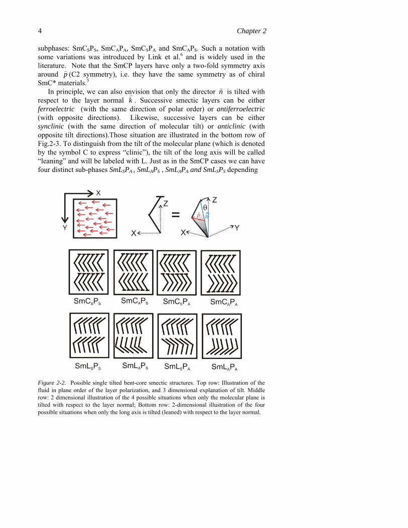
4 Chapter 2 subphases: SmCSPS, SmCAPA, SmCSPA and SmCAPS. Such a notation with some variations was introduced by Link et al.6 and is widely used in the literature. Note that the SmCP layers have only a two-fold symmetry axis around p (C2 symmetry), i.e. they have the same symmetry as of chiral SmC* materials.5
In principle, we can also envision that only the director n is tilted with respect to the layer normal k . Successive smectic layers can be either ferroelectric (with the same direction of polar order) or antiferroelectric (with opposite directions). Likewise, successive layers can be either synclinic (with the same direction of molecular tilt) or anticlinic (with opposite tilt directions).Those situation are illustrated in the bottom row of Fig.2-3. To distinguish from the tilt of the molecular plane (which is denoted by the symbol C to express “clinic”), the tilt of the long axis will be called “leaning” and will be labeled with L. Just as in the SmCP cases we can have four distinct sub-phases SmLSPA , SmLAPS , SmLAPA and SmLSPS depending
Figure 2-2. Possible single tilted bent-core smectic structures. Top row: Illustration of the fluid in plane order of the layer polarization, and 3 dimensional explanation of tilt. Middle row: 2 dimensional illustration of the 4 possible situations when only the molecular plane is tilted with respect to the layer normal; Bottom row: 2-dimensional illustration of the four possible situations when only the long axis is tilted (leaned) with respect to the layer normal.

2. PHYSICAL PROPERTIES OF BANANA LIQUID CRYSTALS 5
on the subsequent tilt and polarization direction combinations. In such phases the polar axis is not parallel to the smectic layers and they have Cs symmetry.
On the same grounds one also can imagine that both tilt directions are possible simultaneously.7 Those “double – tilted” situations are labeled both with C and L, where the tilt independently can be the parallel or antiparallel to each other. Taking into account that the layer polarizations can either be parallel or antiparallel, we have altogether eight different subphases as illustrated in Fig. 2-4.
Although in all situations the individual layer polarizations are not parallel to the smectic layers, the out of layer components average out in case of the anti-leaning structures, and their macroscopic symmetry would be the same as of the SmAP (for anticlinic situations, such as SmCALAPA and SmCALAPS) or as of SmCP (for synclinic situations, such as SmCSLAPA and SmCSLAPS ). It is important to note that the SmCLP structures can be equivalently described by a tilt of the molecular plane and a rotation of the layer polarization P about the long axis n by an angle φ. If φ=0 or π then we have the SmCP case, φ=π/2 or 3π/2 correspond to the SmLP situations, otherwise we have the SmCLP phase. Double – tilted layers have triclinic symmetry, i.e., they are symmetric only with respect to a 360o rotation around the polar axis P (Schoenflis notation: C1). Such a structure was theoretically predicted by de Gennes8 and was labeled as SmCG (“G” stands for generalized) without specifying bent-core molecules.
So far we have considered only those cases where the center of masses of molecules had periodicity only in one direction, i.e., when the material can be considered solid in 1 dimension and fluid in the other two directions. The theoretically possible 2-dimensional solid structures are illustrated in Fig. 2-5 to Fig. 2-6. The situation shown in the upper row of Fig. 2-5 assumes an intercalated layer structure. In this case the hydrophobic hydrocarbon chains have to the in close proximity with the aromatic bent-cores, which usually are not favored entropically, and lead to a nano-segregation as shown in the bottom row of Fig. 2-5.
Other two possibilities for two - dimensional solid structures are illustrated in Fig. 2-6. In the first case we assume disc-shape aggregates of several molecules (four in the drawing). To describe the orientations of the individual molecules in the aggregates we shall characterize it by the triplet of p , n , m unit vectors. We can express the aggregate with four triplets with coordinates in the X,Y,Z lab system with unit vectors x , y and z , as follows {[ z , y , x ], [- z , x ,- y ], [ x , y , z ], [- x , y ,- z ]}. These aggregates then form fluid stacks (columns) in the z direction and periodic structures in the XY plane. The last possibility to form 2-dimensional structures is illustrated in the bottom row of Fig. 2-6. This corresponds to any local

6 Chapter 2 structures of SmAP, SmCP, SmLP or SMCLP illustrated in Fig. 2- 2 to 4, except that within each layers the polarization is assumed to alternate. This alternation imposes an entropic restriction to position of the center of molecules along the Y direction resulting in a rectangular periodicity in the YZ plane. In the neighbor rectangles the polarizations can either be parallel or antiparallel to each other corresponding to the PS or PA situations of Fig. 2-2 to 4. Theoretically this last situation alone may have 2+4+4+8=18 subphases
Figure 2-3. (a) Possible double - tilted bent-core smectic structures. Top row: Illustration of the fluid in plane orders of the layer polarization (either uniform or modulated), and 3 - dimensional explanation of tilt. Middle and bottom rows: 2 dimensional illustrations of the eight possible situations; (b) Graphical explanation of the SmCLP structures in term of two rotation angles θ and φ.

2. PHYSICAL PROPERTIES OF BANANA LIQUID CRYSTALS 7
Figure 2-4. Schematic representation of the intercalated layer structures.
.
Figure 2-5. 2-dimensional periodic structures formed by local disc like aggregation of bent-core molecules (a) or due to antiferroelectric in-plane ordering (b).
8 Chapter 2 2. EXPERIMENTAL RESULTS
2.1 Phase Structures
Experimental observations of the smectic and columnar phases of bent-core liquid crystal phases were pioneered by groups in Tokyo 9, Boulder6, Berlin10, Halle11, Budapest12, and several other places.13,14 In the last several years the research has quickly broadened with very intensive experimental studies carried out all around the world. Activities of this “banana mania” have been recently reviewed in several papers.15
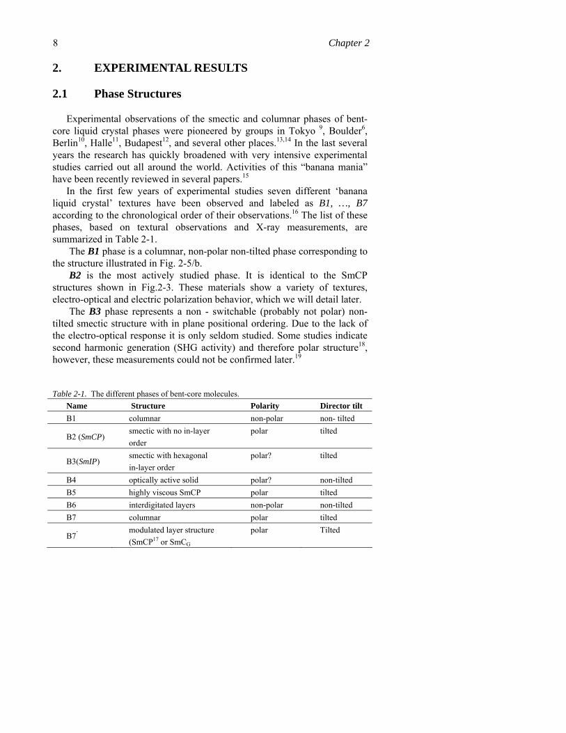
In the first few years of experimental studies seven different ‘banana liquid crystal’ textures have been observed and labeled as B1, …, B7 according to the chronological order of their observations.16 The list of these phases, based on textural observations and X-ray measurements, are summarized in Table 2-1.
The B1 phase is a columnar, non-polar non-tilted phase corresponding to the structure illustrated in Fig. 2-5/b.
B2 is the most actively studied phase. It is identical to the SmCP structures shown in Fig.2-3. These materials show a variety of textures, electro-optical and electric polarization behavior, which we will detail later.
The B3 phase represents a non - switchable (probably not polar) non-tilted smectic structure with in plane positional ordering. Due to the lack of the electro-optical response it is only seldom studied. Some studies indicate second harmonic generation (SHG activity) and therefore polar structure18, however, these measurements could not be confirmed later.19
Table 2-1. The different phases of bent-core molecules. Name Structure Polarity Director tilt B1 columnar non-polar non- tilted
B2 (SmCP) smectic with no in-layer order
polar tilted
B3(SmIP) smectic with hexagonal in-layer order
polar? tilted
B4 optically active solid polar? non-tilted B5 highly viscous SmCP polar tilted B6 interdigitated layers non-polar non-tilted B7 columnar polar tilted
B7’ modulated layer structure (SmCP17 or SmCG
polar Tilted
2. PHYSICAL PROPERTIES OF BANANA LIQUID CRYSTALS 9
The nature of the B4 phase is a challenge of the current studies, although the first description of chirality in the banana phases was on the B4 phase. It is a solid phase, but it is currently not clear if this is some kind of crystal20 or hexatic twist grain boundary (TGB) phase21, or something else. X-ray diffraction measurements indicate broader peaks in the wide angle range than in the B3 phase that appears at higher temperatures. This would indicate less ordered packing in the short range, or layered packing with short range order. Freeze fracture electron microscopy studies suggest a structure similar to the lyotropic sponge phase.22 Notably this structure is very similar to that proposed for an optically isotropic ferroelectric phase consisting of random SmCAPS nanodomains.23
The B5 name was originally assigned to a switchable phase, which appeared below the B2 phase and showed somewhat more complex X-ray profile24 than of B2. However, investigations on freely suspended films showed that it has the same symmetry as of the B216, so it seems that there is no need for a separate name.
The B6 phase is an intercalated smectic structure such as shown in Fig. 2-5/a without long range order in the YZ plane. In this phase the layer periodicity is smaller than half length of the molecules. As we mentioned before, this packing makes contacts between the aromatic rigid bent-core and the flexible tails, so it is not favored, explaining that experimentally it is found only in short chain materials.16
The high temperature phase that appears directly below the isotropic phase showing characteristic helical filamentary growth in cooling25 is denoted as B7. Later measurements showed that similar helical structures may appear in materials with different structures, and they correspond to at least two distinct phases. The exact structures of these phases are still under active debate, which we will detail later.
The polar smectic A (SmAP)26 phase and nematic structures27 were observed only after the Bi (i=1,…7) nomenclature was introduced and they have not been assigned with those symbols.
So far there is only one report26 on non-tilted SmAPA phase corresponding to Fig. 2-2/b. This phase does not show electro-optical switching, nor birefringence change, although polarization current measurements clearly show a large (almost 1000nC/cm2) antiferroelectric polarization value.
Nematic phases exhibiting purely orientational order are rather uncommon in bent-core compounds probably due to the tendency of the periodic positional ordering we mentioned above (see Fig. 2-1) However, very recently, a number of new bent-core compounds with nematic phases have been synthesized.27-29 and their physical properties are currently being investigated.30-32 Light scattering studies in the uniaxial nematic phase31, and
10 Chapter 2 recent NMR measurements in the isotropic phase31, reveal drastically slower fluctuations in bent-core compounds than observed in typical calamitics. This is because their viscosities are about 2 orders of magnitude larger than of normal calamitic materials.34 This behavior is also consistent with the cluster concept illustrated in Fig. 2-1 and corroborated by recent NMR measurements.35 Simultaneously there has been a surge in theoretical studies13,36-38 predicting intriguing new thermotropic nematic and isotropic structures. These including uniaxial behavior31, field induced biaxiality32 and biaxial phases39.
2.2 SmCP materials
2.2.1 Electro-optic properties
Although the very first report on bent-core smectic materials showed ferroelectric switching without rotation of the optical axis during switching thus indicating SmAP structure corresponding to Fig. 2-2/a4 soon it became clear that they rather form tilted phases40,41 and show antiferroelectric switching6,12. This is because of the typically much larger than 200 nC/cm2 layer polarization, which favor antiferroelectric arrangement due to dipole - dipole interactions.
Interestingly it was observed that the switching between the field-induced ferroelectric states under typically above 3V/μm rectangular electric fields is either accompanied by rotation of the optic axis, or it takes place without any rotation of the optical axis. Usually both types of textures are present in one sample, typically under cooling from the isotropic phase mainly the non-rotating domains showed up, whereas when heating from the lower temperature B3 phase, mainly the rotating type domains formed. This strange behavior was first explained by Link et al.6 by realizing that the domains that do not show rotation of the optic axis under rectangular fields have SmCSPA, whereas the other domains have SmCAPA structures (see cartoons in Fig. 2-3).
2.2.2 Layer chirality
Importantly it was also realized by the Boulder group6, that the combination of polar packing and the tilt of the molecular planes gives the smectic layers a chiral structure, which is usually referred as layer chirality. Since the molecules (at least those studied first) do not contain any chiral carbons, smectic layers can form two different structures that are non-superposable mirror images of each other. To distinguish between these two structures, we can define the chiral order parameter as42
2. PHYSICAL PROPERTIES OF BANANA LIQUID CRYSTALS 11
( )2 k n p k nχ ⎡ ⎤ ⎡ ⎤= × ⋅ ⋅⎣ ⎦⎣ ⎦ , 1
where k , n and p are unit vectors normal to the smectic layers, along the director and the layer polarization, respectively. This order parameter has the correct symmetry as a pseudoscalar, and it is invariant under the symmetries n → − n and k → − k . Right- and left-handed mirror image layers have opposite signs of χ, which ranges from −1 to +1. These possibilities for polar and tilt order lead to two possibilities for the layer chirality. If the smectic phase is ferroelectric44-45 and synclinic (SmCSPS), or if it is antiferroelectric40,41,46 and anticlinic (SmCAPA), then the material has a homogeneously chiral structure, with the same sign of χ in all layers. By contrast, if the smectic phase is ferroelectric and anticlinic (SmCAPS), or if it is antiferroelectric and synclinic (SmCSPA), then the material has alternating right- and left-handed chiral layers, with alternating positive and negative values of χ. This latter possibility is generally called a “racemic” structure, although we might use the alternative term “antichiral” 47 to emphasize the rigid alternation from layer to layer. All these possibilities with their typical textures are shown in Fig. 2-7.
The textures of racemic SmCSPA phase usually consist of fan-shaped domains decorated with a few micron wide stripes, which consist of oppositely tilted synclinic domains. In homochiral SmCAPA structure the optical axis is parallel to the layer normal regardless of the handedness of the domains. The antiferroelectric (AFE) arrangement can be easily switched to ferroelectric (FE) by applying an external electric field of typically larger than 3-5V/μm and f<10kHz electric fields. The racemic FE state is anticlinic (SmCAPS) and the optical axes are parallel to the layer normal regardless of the sign of the electric field. The homochiral FE state is synclinic (SmCSPS) and the optical axes make angles ±θ with the layer normal, depending on the sign of the electric field.
2.2.3 Light scattering properties
In addition to these differences between anticlinic and synclinic structures in the behavior of the optical axis during switching by electric fields, there is a difference in their light scattering properties, too. The synclinic structures (AFE state of the racemic and FE state of the chiral structures) scatter light, whereas the anticlinic structures (FE state of the racemic and AFE state of the chiral structures) are transparent.46 This is due

12 Chapter 2
Figure 2-6. Definition of the layer chirality. Left (right) - handed layer: the average molecular axis is oriented (anti)clockwise from the layer normal. This can be envisioned relative to a left (right) hand: if the thumb of a left (right) hand is pointing in the direction of layer polarization P, the direction of the curling of the fingers represents the direction of the deviation of the molecular axis from the layer normal n. (a): Orthogonal views of the racemic SmCP phase of non-chiral banana-shaped molecules and polarizing microscope textures viewed in tilt plane in antiferroelectric (AFE) and ferroelectric(FE) states (left and right columns). The “Polar plane” contains the layer normal and the layer polarization (P), whereas the “Tilt plane” is perpendicular to P. The molecular plane is tilted with respect to the layer normal. The single dashed line (------) indicates synclinic interfaces in anticlinic state, whereas double dashed lines (====) represents defect walls separating synclinic layers with opposite tilt directions. (b): Orthogonal views of the chiral SmCP phase of non-chiral banana-shaped molecules and polarizing microscope textures viewed in tilt plane in antiferroelectric (AFE) and ferroelectric (FE) states (left and right columns). The “Polar plane” contains the layer normal and the layer polarization (P), whereas the “Tilt plane” is perpendicular to P. The molecular plane is tilted with respect to the layer normal. In (a) and (b) (-----) indicates synclinic interfaces in anticlinic state, whereas (====) represents defect walls separating synclinic layers with opposite tilt directions. The pictures represent 100-μm x 70-μm areas.
to the fact that the differently tilted synclinic domains are separated by defect walls, which are observable even without polarizers. Antiferroelectric and ferroelectric textures of the chiral state viewed without polarizers are shown in Fig. 2-8. In the anticlinic AFE state (a) only focal conic defects are present due to the imperfect layer alignment, whereas in the synclinic FE state (b) the texture is full of defect walls separating domains with different handedness. Defects cause light - scattering because the refractive index of the defect is different from the uniform areas. Focal conic defects of Fig. 2-8/a cause only a few percentage of scattering, whereas the defect walls of
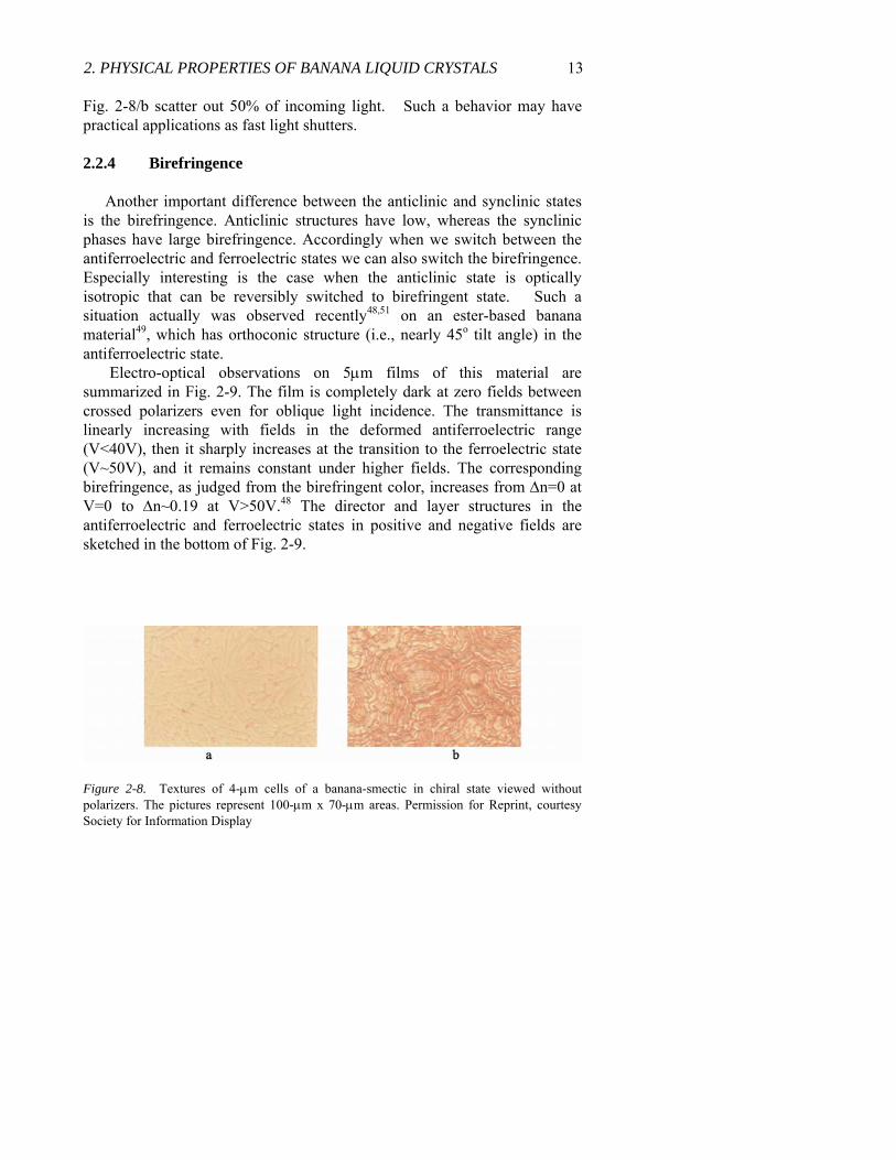
2. PHYSICAL PROPERTIES OF BANANA LIQUID CRYSTALS 13 Fig. 2-8/b scatter out 50% of incoming light. Such a behavior may have practical applications as fast light shutters.
2.2.4 Birefringence
Another important difference between the anticlinic and synclinic states is the birefringence. Anticlinic structures have low, whereas the synclinic phases have large birefringence. Accordingly when we switch between the antiferroelectric and ferroelectric states we can also switch the birefringence. Especially interesting is the case when the anticlinic state is optically isotropic that can be reversibly switched to birefringent state. Such a situation actually was observed recently48,51 on an ester-based banana material49, which has orthoconic structure (i.e., nearly 45o tilt angle) in the antiferroelectric state.
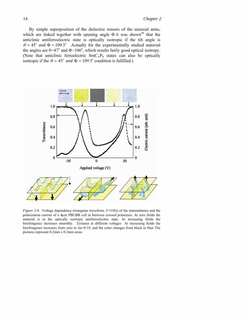
Electro-optical observations on 5μm films of this material are summarized in Fig. 2-9. The film is completely dark at zero fields between crossed polarizers even for oblique light incidence. The transmittance is linearly increasing with fields in the deformed antiferroelectric range (V<40V), then it sharply increases at the transition to the ferroelectric state (V~50V), and it remains constant under higher fields. The corresponding birefringence, as judged from the birefringent color, increases from Δn=0 at V=0 to Δn~0.19 at V>50V.48 The director and layer structures in the antiferroelectric and ferroelectric states in positive and negative fields are sketched in the bottom of Fig. 2-9.
Figure 2-8. Textures of 4-μm cells of a banana-smectic in chiral state viewed without polarizers. The pictures represent 100-μm x 70-μm areas. Permission for Reprint, courtesy Society for Information Display
14 Chapter 2
By simple superposition of the dielectric tensors of the uniaxial arms, which are linked together with opening angle Φ it was shown48 that the anticlinic antiferroelectric state is optically isotropic if the tilt angle is
45 109.5o oandθ = Φ = Actually for the experimentally studied material the angles are θ=47o and Φ~106o, which results fairly good optical isotropy. (Note that anticlinic ferroelectric SmCAPS states can also be optically isotropic if the 45 109.5o oandθ = Φ = condition is fulfilled.)
Figure 2-9. Voltage dependence (triangular waveform, f=31Hz) of the transmittance and the polarization current of a 4μm PBUBB cell in between crossed polarizers. At zero fields the material is in the optically isotropic antiferroelectric state. At increasing fields the birefringence increases smoothly. Textures at different voltages At increasing fields the birefringence increases from zero to Δn=0.19, and the color changes from black to blue The pictures represent 0.2mm x 0.2mm areas.
2. PHYSICAL PROPERTIES OF BANANA LIQUID CRYSTALS 15
The optically isotropic structures are in fact unusually frequent in case of bent-core compound compared to the calamitic LCs, and were found also on materials with opening angles far from the tetrahedratic angle both in antiferroelectric58,57 and ferroelectric23 phases. In these cases the absence of birefringence were explained assuming arbitrarily oriented sub-visible size birefringent domains.57 Such materials are usually referred as “dark conglomerates.20,63
2.2.5 Optical activity
Chirality is usually seen optically in the form of rotation of the optical axis of a linearly polarized light crossing a chiral material (optical activity). In isotropic liquids optical activity requires chiral molecules, which results in typically of about 1 degree rotation of a light crossing 1 cm slab. In liquid crystals molecular chirality leads to helical structure, which enhances the optical activity so that the optical rotation (OR) can be as large as 100 deg/μm in some short pitch cholesteric or SmC* materials.
In achiral rod-shape molecules one does not expect any optical activity, but as we have seen achiral bent-core liquid crystals can have chiral layer structures. An interesting question therefore if we see optical activity in those materials. Observing planar textures of bent-core liquid crystals between slightly uncrossed polarizers, it is indeed often found40,50-59 that the texture splits into darker and brighter domains. For polarizers uncrossed in the opposite sense the darker and brighter domains exchange and for crossed polarizers they have the same brightness. This shows optical activity with OR~0.1-1 deg/μm. Except for the example demonstrated in Ref. [51], optical rotations were seen only on optically isotropic samples, although not all optically isotropic samples show observable optical rotation60, or not in any alignment52. The reason for the optical activity is presently under active debate.
First it was argued to be due to a chiral molecular configuration characteristic of the particular type of bent-shape molecules, such as twisted or propeller shape (conformational chirality). The concept of conformational chirality was supported by simulations by Earl et al.61, and was demonstrated by the observation that doping calamitic cholesteric liquid crystal by achiral bent-core molecules can lead to a decrease of the helical pitch, indicating an enhanced rotatory power of the mixture.62 Unfortunately there is no proof that the decrease of the pitch is not due to a decrease of the twist elastic constant caused by the addition of bent-core units. Although the conformational chirality is usually not questioned in the solid B4 phase20, its role has been questioned by Walba et al.20 by arguing that these chiral

16 Chapter 2 conformations have very short lifetime, therefore they average out in fluid smectic, such as SmCP or SmCG phases.
As an alternative to conformational chirality, Ortega et al.57 modeled the SmCAPA with a locally achiral dielectric tensor where optical axis rotating with a pitch of two layers. This indicates that layer scale structural chirality can lead to observable optical rotation. Recently Hough and Clark have extended this model to other SmCP subphases, such as SmCSPS, SmCAPS and SmCSPA. They have shown63 that the optical rotation of the unhelixed SmCSPS is comparable to that of SmCAPA. In addition they have also shown that even the racemic SmCAPS and SmCSPA may also present optical activity for lights not parallel or perpendicular to the smectic layers. It was found that the calculated optical rotation values have the same order of magnitude that is usually observed. They may also account for the observations23,64
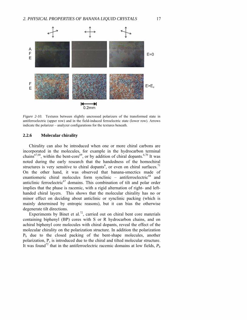
where optical activity was observed only after repeated heating - cooling cycles to the crystalline, or B4 phase65,66 when surface memory effects may result in tilted layers with respect to the substrates. One therefore may be inclined to believe that there is no need of conformation chirality to explain the optical activity in the fluid tilted smectic phases, because the layer scale chirality can explain all observations. However, experimentally it is usually observed that the size of the domains with opposite optical rotation is typically in the range of 100-300μm, whereas the size of domains with uniform layer chirality is only about 2-10μm, i.e. an order of magnitude smaller. Since the optical activity is detected typically on optically isotropic samples63,65 where the homochiral domains are not visible the difference between the homochiral and optically active domains was not obvious until recently when the optically active domains were observed even in the SmCSPS state51(see Fig. 2-10). It is clearly seen that the domain boundaries do not correlate to those of different layer-chirality, which challenges the layer-scale chirality concept. In all cases we have observed an evolution of the optically active domains after several cooling-heating cycles, and we suspect that they always related to surface memory effects. The optically active domains form only in the crystalline or close to crystalline structures such as B4 and B3 phases and those domains are imprinted in the surfaces.
2. PHYSICAL PROPERTIES OF BANANA LIQUID CRYSTALS 17
Figure 2-10. Textures between slightly uncrossed polarizers of the transformed state in antiferroelectric (upper row) and in the field-induced ferroelectric state (lower row). Arrows indicate the polarizer – analyzer configurations for the textures beneath.
2.2.6 Molecular chirality
Chirality can also be introduced when one or more chiral carbons are incorporated in the molecules, for example in the hydrocarbon terminal chains67,68, within the bent-core69, or by addition of chiral dopants.6,70 It was noted during the early research that the handedness of the homochiral structures is very sensitive to chiral dopants6, or even on chiral surfaces.71 On the other hand, it was observed that banana-smectics made of enantiomeric chiral molecules form synclinic – antiferroelectric44 and anticlinic ferroelectric67 domains. This combination of tilt and polar order implies that the phase is racemic, with a rigid alternation of right- and left-handed chiral layers. This shows that the molecular chirality has no or minor effect on deciding about anticlinic or synclinic packing (which is mainly determined by entropic reasons), but it can bias the otherwise degenerate tilt directions.
Experiments by Binet et al.72, carried out on chiral bent core materials containing biphenyl (BP) cores with S or R hydrocarbon chains, and on achiral biphenyl core molecules with chiral dopants, reveal the effect of the molecular chirality on the polarization structure. In addition the polarization Pb due to the closed packing of the bent-shape molecules, another polarization, Pc is introduced due to the chiral and tilted molecular structure. It was found72 that in the antiferroelectric racemic domains at low fields, Pb
18 Chapter 2 of the synclinic - racemic domains averages out but, due to the synclinic order and of the chiral molecules, a Pc normal to the tilt plane similar to the SmC* phase is possible. In this case, a relatively low electric field is able to unwind the helical structure, but would not be able to switch the antiferroelectric Pb, which requires a higher threshold. Upon this antiferroelectric to ferroelectric transition, the synclinic structure becomes anticlinic and Pc vanishes, leaving only a Pb. Although the textural observations were consistent with this picture it was not possible to measure Pc separately, because in case of the enantiomeric molecules isolated metastable chiral (anticlinic antiferroelectric) domains are also present, where both Pc and Pb average out below the transition to the ferroelectric state where the effective polarization becomes Pb+Pc. Very recently however the chirality – induced polarization Pc could be separated from the bent-core packing related polarization Pb
73. These studies were carried out on
binary mixtures of an achiral fluorinated (B-2F) and a chiral material (B-Ch) where a chiral cholesterol unit was attached to one end of the bent core. At low B-Ch concentrations Pc could be switched and measured below Pb was switched. It is found that Pc is an order of magnitude smaller than Pb, but larger than of the pure B-Ch. This is because the molecular dipoles of B-2F are much larger than of B-Ch due to the presence of the highly polar fluorine atoms.
2.2.7 Chirality transformations
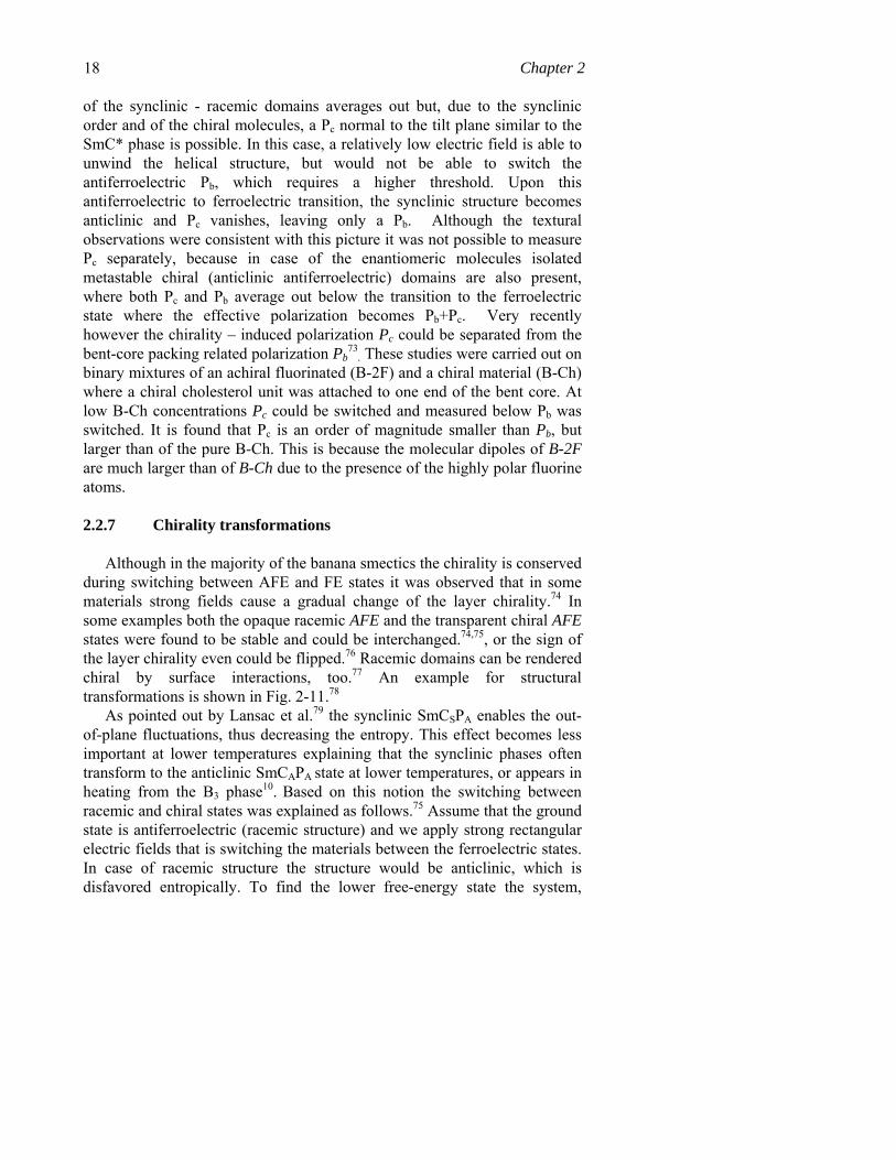
Although in the majority of the banana smectics the chirality is conserved during switching between AFE and FE states it was observed that in some materials strong fields cause a gradual change of the layer chirality.74 In some examples both the opaque racemic AFE and the transparent chiral AFE states were found to be stable and could be interchanged.74,75, or the sign of the layer chirality even could be flipped.76 Racemic domains can be rendered chiral by surface interactions, too.77 An example for structural transformations is shown in Fig. 2-11.78
As pointed out by Lansac et al.79 the synclinic SmCSPA enables the out-of-plane fluctuations, thus decreasing the entropy. This effect becomes less important at lower temperatures explaining that the synclinic phases often transform to the anticlinic SmCAPA
state at lower temperatures, or appears in heating from the B3 phase10. Based on this notion the switching between racemic and chiral states was explained as follows.75 Assume that the ground state is antiferroelectric (racemic structure) and we apply strong rectangular electric fields that is switching the materials between the ferroelectric states. In case of racemic structure the structure would be anticlinic, which is disfavored entropically. To find the lower free-energy state the system,
2. PHYSICAL PROPERTIES OF BANANA LIQUID CRYSTALS 19 therefore has to drift to the synclinic ferroelectric state, which is chiral. After field removal this chiral state becomes antiferroelectric and anticlinic, so it can be only metastable. The more stable racemic state can reform either by nucleation process, or it can be driven back to the synclinic racemic state under triangular electric fields, because during switching it stays longer in the antiferroelectric than in the ferroelectric state.75
All these chirality transformations mean that during the switching the molecules not strictly rotate about the layer normal around the tilt cone, but in some extent also around their long axis. As far as we know this model was first put forward in the 2nd Banana workshop held in Boulder, Colorado70 and later discussed in several papers.58,76. The rotation of the director around the tilt cone preserves the layer chirality, whereas during rotation around the long axis the chirality changes signs. This rotation is faster than the rotation around the cone, and is permissible only in racemic domains. Indeed it is usually observed that racemic switching is faster than chiral switching.74
E>20V/μm, f=1Hz, t>30s
Antiferroelectric racemic
Ferroelectric chiral, bistable
E>20V/μm, f>500Hz, t>30s
Figure 2-11. Example of textural transformation observed under different electric fields on a 10μm film of a biphenyl based material.
20 Chapter 2 2.3 The B7 materials
2.3.1 Textures
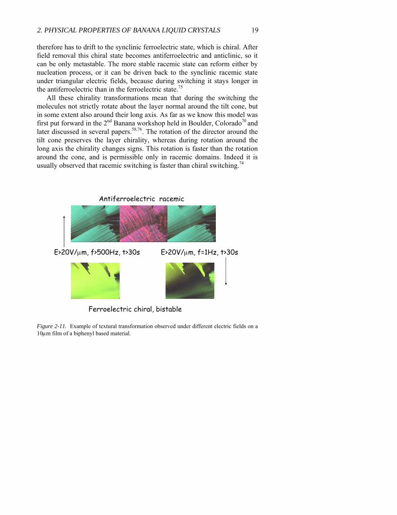
Figure 2-12. Textures of helical filaments forming on cooling from the isotropic phase83 (upper row) and the proposed telephone cord structure consisting of smectic layers.
As mentioned before the B7 label denotes materials with peculiar helical super-structures25,80-82 including helical filaments83 and banana leaf– shaped domains.84 The helical filaments with a proposed telephone – wire type structure, where the smectic layers form concentric cylinders as shown in Fig. 2-12.
Other type of interpretation of the textures was proposed by Nastishin et al.85, who suggested that the B7 phase is a smectic and columnar phase at the same time. The geometry of the helical filaments (ribbons) is that one of the central region of a screw disclination with a giant Burgers vector split into two disclination lines of strength ½, which bound the ribbon.
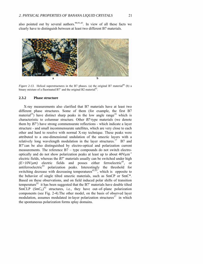
The spontaneous chirality that result in the telephone wire type textures at the transition, persist in the fully formed B7 phase, resulting in various astonishing helical superstructures80, as illustrated in Fig. 2-13.
Since the first observations many other materials with similar textures have appeared in the literature86,87,93 however, it is not clear that all the materials with B7 textures have really the same structure. For example Bedel et al. found that materials studied in Ref. [86] are not miscible with the reference B7 compound [25]. Ortega et al.88 observed B7-like textures in a compound classified in principle as B189 after a prolonged electric-field treatment. Other contradictory reports on the features of the B7 phase are
2. PHYSICAL PROPERTIES OF BANANA LIQUID CRYSTALS 21 also pointed out by several authors.90,91,43. In view of all these facts we clearly have to distinguish between at least two different B7 materials.
Figure 2-13. Helical superstructures in the B7 phases. (a) the original B7 material80 (b) a binary mixture of a fluorinated B7’ and the original B2 material92.
2.3.2 Phase structure
X-ray measurements also clarified that B7 materials have at least two different phase structures. Some of them (for example, the first B7 material25) have distinct sharp peaks in the low angle range16 which is characteristic to columnar structure. Other B7-type materials (we denote them by B7’) have strong commensurate reflections - which indicate a layer structure - and small incommensurate satellites, which are very close to each other and hard to resolve with normal X-ray technique. These peaks were attributed to a one-dimensional undulation of the smectic layers with a relatively long wavelength modulation in the layer structures.17 B7 and B7’can be also distinguished by electro-optical and polarization current measurements. The reference B7 – type compounds do not switch electro-optically and do not show polarization peaks at least up to about 40Vμm-1
electric fields, whereas the B7’ materials usually can be switched under high (E>10V/μm) electric fields and posses either ferroelectric45, or antiferroelectric93 polarization peaks. Interestingly the threshold for switching decrease with decreasing temperatures45,93, which is opposite to the behavior of single tilted smectic materials, such as SmCP or SmC*. Based on these observations, and on field induced polar shifts of transition temperature92 it has been suggested that the B7’ materials have double tilted SmCLP (SmCG)92 structures, i.e., they have out–of–plane polarization components (see Fig. 2-4).The other model, on the basis of observed layer modulation, assumes modulated in-layer polarization structures17 in which the spontaneous polarization forms splay domains.

22 Chapter 2 2.4 Free-standing filaments
Filaments usually can be pulled only in materials, which become solid during the fiber extruding process, like spider silk,94 polymer fibers or silica glass fibers. It is also known that columnar liquid crystalline phases of disc-shaped molecules are one-dimensional fluids and they can form stable filaments.95 The stability of the columnar strands can be explained by taking into account the bulk energy due to compression of the columnar structure, in addition to the surface contribution of the Newtonian fluids. Low molecular weight liquid crystals of rod shape molecules do not form fibers and it was observed96 that nematic and smectic A bridges collapse at slenderness ratios of R π≈ and at R=4.2, respectively. Smectic liquid crystals of rod-shape molecules generally tend to form thin films,97 similar to cell membranes. Repeated efforts in the past 20 years have failed to produce stable smectic filaments.
In the effort to make free-standing films of the first B7 material it was found that instead of films they form free-standing strands25 just like columnar liquid crystals of disc-shape molecules.95 Such observation was confirmed with other B7 materials98, and later it was found that the B7’ and B2 type banana-smectics also form strands of fibers.99 Although the most stable fibers are the B7 materials with slenderness ratio as large as 5000, the B7’ and B2 fibers also have aspect ratios over 1000 and 100, respectively. The values are orders of magnitudes larger than of the Rayleigh-Plateau limit100 of Newtonian isotropic fluids and of nematic and smectic liquid crystals of rod-shape molecules. 96
B7 and B2 type fibers are completely stable, and are much thinner (1.5-10μm) than conventional extruded fibers (10-100μm). Interestingly metastable fibers could be pulled even in the nematic phase of bent-core materials and their slenderness ratios are much larger than those observed in nematic liquid crystals of rod-shape molecules.96 This behavior is typical for viscoelastic fluid fibers101, and indicates that nematic bent-core liquid crystals may be considered as fluid agglomerates of smectic clusters.31
The fibers possess helical properties: they form a helix when shrinking, or particles attached to it rotate during pulling and shrinking). Under dc electric fields applied along bundles of filaments some of the individual helical fibers unwind, then rupture, whereas others remain stable. This indicates polar nature of the individual fibers: those that rupture may have polarization antiparallel to the field; those that stabilize are polarized parallel to the field. Under alternating fields periodic flow may occur along the fibers. The direction of the flow depends on the sign of the electric fields, but in the different strands it can be opposite. In the B2 bundles the flow effects average out and the overall diameter does not change. In the B7

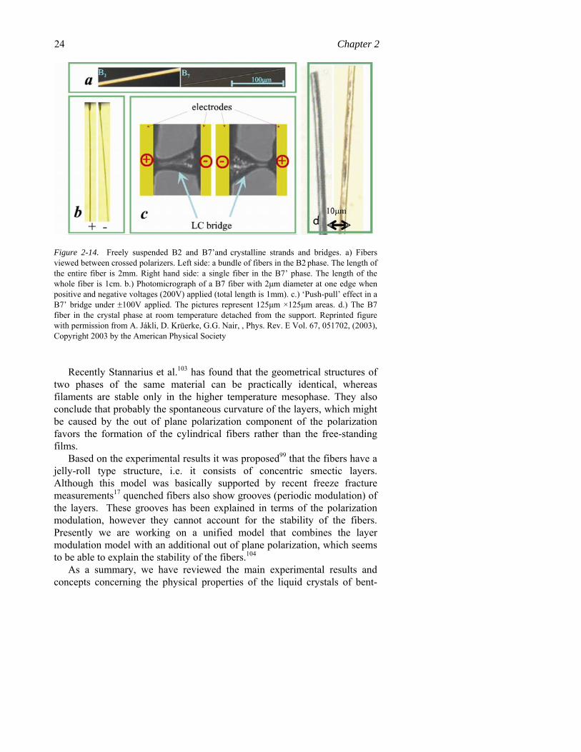
2. PHYSICAL PROPERTIES OF BANANA LIQUID CRYSTALS 23 fibers, however the flow direction seem to be the same in all strands and a net flow is observed. Relatively thick and short B7’ bridges posses’ strange push-pull effects, as shown in Fig. 2-14/c: one polarity can pull all the material from one side to the other and the other polarity can reverse it. Such effects were not observed in the B2 bridges indicating structural differences.
In the long single B7 fibers a transversal vibration could be observed under electric fields applied along the fibers. Interestingly the vibration takes place with the frequency of the electric field: the string is bent for one polarity of the voltage and becomes straight again for the other polarity. An example is shown in Fig. 2-14/b, where the maximum deviation from the straight direction is about 5 degrees. The string is anchored at the end plates and moves sideways in the middle. The sensitivity of the length of the fiber to the sign of the field confirms that the fibers are polar. When the polarization is parallel to the applied field the electric field facilitates the fiber formation, which (at constant end-to-end distances) means that the fiber should be bent. When the polarization is antiparallel to the electric field the fiber formation is not favored just minimizing the length of the fiber. When the fiber snaps back after field reversal, or when the vibration is induced by a pulse we observe a small vibration with a natural frequency of about 10 Hz for strings of a D= 2μm diameter and L=0.5mm length. From this the surface tension of the filaments were estimated as γ~30 mN/m, which is in good agreement with a more recent and more precise results of γ=26 mN/m obtained by Eremin et al.102 in a measurement wherein they have pulled a B7 filament with the cantilever of an Atomic Force Microscope and measured the force.
It is very important to note that the fibers remain stable even when cooled to the crystal phase, thus one can detach the fiber from the support and study them by methods that are not available when they sit between the supports. Parts of typical fibers in the B2, B7 and B7’ fibers and bridges, in between the supports and when detached in their crystalline phase, are shown in Fig. 2-14/d.
24 Chapter 2
Figure 2-14. Freely suspended B2 and B7’and crystalline strands and bridges. a) Fibers viewed between crossed polarizers. Left side: a bundle of fibers in the B2 phase. The length of the entire fiber is 2mm. Right hand side: a single fiber in the B7’ phase. The length of the whole fiber is 1cm. b.) Photomicrograph of a B7 fiber with 2μm diameter at one edge when positive and negative voltages (200V) applied (total length is 1mm). c.) ‘Push-pull’ effect in a B7’ bridge under ±100V applied. The pictures represent 125μm ×125μm areas. d.) The B7 fiber in the crystal phase at room temperature detached from the support. Reprinted figure with permission from A. Jákli, D. Krüerke, G.G. Nair, , Phys. Rev. E Vol. 67, 051702, (2003), Copyright 2003 by the American Physical Society
Recently Stannarius et al.103 has found that the geometrical structures of
two phases of the same material can be practically identical, whereas filaments are stable only in the higher temperature mesophase. They also conclude that probably the spontaneous curvature of the layers, which might be caused by the out of plane polarization component of the polarization favors the formation of the cylindrical fibers rather than the free-standing films.
Based on the experimental results it was proposed99 that the fibers have a jelly-roll type structure, i.e. it consists of concentric smectic layers. Although this model was basically supported by recent freeze fracture measurements17 quenched fibers also show grooves (periodic modulation) of the layers. These grooves has been explained in terms of the polarization modulation, however they cannot account for the stability of the fibers. Presently we are working on a unified model that combines the layer modulation model with an additional out of plane polarization, which seems to be able to explain the stability of the fibers.104
As a summary, we have reviewed the main experimental results and concepts concerning the physical properties of the liquid crystals of bent-
2. PHYSICAL PROPERTIES OF BANANA LIQUID CRYSTALS 25 core molecules. We demonstrated that a number of seminal findings and basically new concepts emerged in the field in the last decade. However scientists regularly explore “unusual”, “surprising” and not understood phenomena, and there are more unexplained observations than well understood ones. We are completely sure that the next decade of the physics of bent-core liquid crystals will bring new physics, and will be as rich in beautiful observations as was the first decade.
3. ACKNOWLEDGEMENTS
This work was supported by the Focused Research Grant: Ferroelectric phenomena in soft matter systems NSF-DMS-0456232.
4. REFERENCES
1. Y. Matsunaga, S. Miyamoto, Mol. Cryst. Liq. Cryst., 237, 311-317, (1993); H.
Matsuzaki, Y. Matsunaga, Liq. Cryst., 14, 105-120, (1993) 2. D . Vorländer, A. Apel, “Die Richtung der Kohlenstoff-Valenzen in
Benzolabkömmlingen (II.).” Berichte der Deutschen Chemischen Gesellschaft, 1101-1109, (1932)
3. Y. Matsunaga, S. Miyamoto, Mol. Cryst. Liq. Cryst., 237, 311-317, (1993); H. Matsuzaki, Y. Matsunaga, Liq. Cryst., 14, 105-120, (1993)
4. T. Niori, T. Sekine, J. Watanabe, T. Furukawa, H. Takezoe, , J. Mater. Chem. 6(7), 1231-1233, (1996); T. Sekine, T. Niori, M. Sone, J. Watanabe, S.W. Choi, Y. Takanishi, H. Takezoe, Jpn. J. Appl. Phys., 36, 6455 (1997); D.R. Link, G. Natale, R. Shao, J.E. Maclennan, N.A. Clark, E. Körblova, D.M. Walba, Science 278, 1924-1927 (1997)
5. R.B. Meyer, L. Liebert, L. Strzelecki, P. Keller, J. Phys. (France) 36, L69-L74 (1975)
6. D.R. Link, G. Natale, R. Shao, J.E. Maclennan, N.A. Clark, E. Körblova, D.M. Walba, Science 278, 1924-1927 (1997)
7. H.R. Brand, P.E. Cladis, H. Pleiner, Eur. Phys. J. B, 6, 347 (1998) 8. P.G. de Gennes, “The Physics of Liquid Crystals”, Clarendon Press, Oxford (1975) 9. Niori, T., Sekine, T., Watanabe, J., Furukawa, T., Takezoe, H., J. Mater. Chem.
6(7), 1231-1233, (1996); Sekine, T., Niori, T., Sone, M., Watanabe, J., Choi, S.W., Takanishi, Y., Takezoe, H., Jpn. J. Appl. Phys., 36, 6455 (1997)
10. G. Heppke, A. Jákli, D. Krüerke, C. Löhning, D. Lötzsch, S. Paus, R. Rauch, K. Sharma, ECLC’97 Abstract book, 34 (1997); Macdonald, R., Kentischer, F., Warnick, P., Heppke, G., Phys. Rev. Lett., 81, 4408 (1998)
11. Weissflog, W., Lischka, C., Scharf, T, Pelzl, G, Diele, S., Kurth, H., Proc. Spie: Int. Soc. Opt. Eng., 3319, 14 (1998), Diele, S., Grande, S., Kurth, H., Lischka, C., Pelzl,
26 Chapter 2
G., Weissflog, W., Wirth, I., Ferroelectrics, 212, 169 (1998); Pelzl, G., Diele, S., Grande, S., Jákli, A., Lischka, C., Kresse, H., Schmalfuss, H., Wirth, I., Weissflog, W., Liq. Cryst., 26, 401 (1999) ; G. Pelzl, S. Diele, A. Jákli, CH. Lischka, I. Wirth, W. Weissflog, Liquid Crystals, 26, 135-139 (1999)
12. Jákli, S. Rauch, D. Lötzsch and G. Heppke, Phys. Rev. E, 57, 6737-6740 (1998), A. Jákli, Ch. Lischka, W. Weissflog, S. Rauch, G. Heppke, Mol. Cryst. Liq. Cryst, 328, 299-307 (1999)
13. H.R. Brand, P.E. Cladis, H. Pleiner, Eur. Phys. J. B, 6, 347 (1998); P.E. Cladis, H.R. Brand, H. Pleiner, Liquid Crystals Today, 9, 1 (1999) ;
14. Nguyen, H.T., Rouillon, J.C., Marcerou, J.P., Bedel, J.P., Barois, P., Sarmento, S., Mol. Cryst. Liq. Cryst., 328, 177 (1999)
15. R. Amaranatha Reddy, C. Tschierske, J. Mater. Chem. (2006); preprint DOI: 10.1039/b504400f; M.B. Ros, J.L. Serrano, M. R. de la Fuente, C. L. Folcia, J. Mater. Chem., 15, 5093 (2005)
16. G. Pelzl, S. Diele, W. Weissflog, Adv. Mater., 11, 707-724 (1999) 17. D.A. Coleman, J. Fernsler, N. Chattham, M. Nakata, Y. Takanishi, E. Körblova,
D.R. Link, R.-F. Shao, W. G. Jang, J.E. Maclennan, O. Mondainn-Monval, C. Boyer, W. Weissflog, G. Pelzl, L-C. Chien, J. Zasadzinski, J. Watanabe, D.M. Walba, H. Takezoe, N.A. Clark, Science, 301, 1204-1211 (2003)
18. T. Sekine, T. Niori, J. Watanabe, H. Takezoe, Jpn. J. Appl. Phys., 36, L1201 (1997); S.W. Choi, Y. Kinoshita, B. Park, H. Takezoe, T. Niori, J. Watanabe, Jpn. J. Appl. Phys., 37, 3408 (1998)
19. F. Kentischer, R. Macdonald, P. Warnick, G. Heppke, Liq. Cryst., 25, 341 (1998) 20. D. Walba, L. Eshdat, E. Körblova, R. K. Shoemaker, Crystal Growth and design, in
print 21. G. Heppke, D. Moro, Science, 279, 1872-1873 (1998) 22. L.E. Hough, M. Spannuth, H.J. Jung, J. Zasadzinski, D. Krüerke, G. Heppke, D.
Walba, N.A. Clark, Bull. Am. Phys. Soc., 50, 223 (2005) 23. G. Liao, S. Stojadinovic, G. Pelzl, W. Weissflog, S. Sprunt, A. Jákli, Physical
Review E, 72, 021710 (2005) 24. S. Diele, S. Grande, H. Kruth, C. Lischka, G. Pelzl, W. Weissflog, I. Wirth,
Ferroelectrics, 212, 169 (1998) 25. G. Pelzl, S. Diele, A. Jákli, CH. Lischka, I. Wirth, W. Weissflog, Liq. Cryst., 26,
135-139 (1999) 26. A. Eremin, S. Diele, G. Pelzl, H. Nadasi, W. Weissflog, J. Salfetnikova, H. Kresse,
Phys. Rev. E, 64, 051707-1-6 (2001) 27. J. Matraszek, J. Mieczkowski, J. Szydlowska, E. Gorecka, Liq. Cryst., 27, 429-436
(2000); I. Wirth, S. Diele, A. Eremin, G. Pelzl, S. Grande, L. Kovalenko, N. Pancenko, W. Weissflog, J. Mater. Chem., 11, 1642-1650 (2001); W. Weissflog, H. Nádasi, U. Dunemann, G. Pelzl, S. Diele, A. Eremin, H. Kresse, J. Mater. Chem, 11, 2748-2758 (2001);
28. E. Mátyus, K. Keserű, J. Mol. Struct., 543, 89 (2001); 29. T.J. Dingemans, E.T. Samulski, Liq. Cryst., 27, 131-136 (2000) 30. K. Fodor-Csorba, A. Vajda, G. Galli, A. Jákli, D. Demus, Macromolecular
Chemistry and Physics, 203, 1556-1563 (2002); S. Demel, C. Slugovc, F Stelzer, K Fodor-Csorba, G. Galli, Macromol. Rapid. Commun. 2003, 24, 636
31. S. Stojadinovic, A. Adorjan, H. Sawade, A. Jakli, and S. Sprunt, “Phys. Rev. E, Rapid Communications 66, 060707-1- 4 (2002)
32. J. Olivares, S. Stojadinovic, T. Dingemans, S. Sprunt, and A. Jakli, Phys. Rev. E 68, 041704-1-6 (2003)
2. PHYSICAL PROPERTIES OF BANANA LIQUID CRYSTALS 27
33. V. Domenici, M. Geppi, C. A. Veracini, R. Blinc, A. Lebar, and B. Zalar, J. Phys. Chem. B, 109, 769 (2005).
34. D. Wiant, J. T. Gleeson, N. Eber, K. Fodor-Csorba, A. Jakli, and T. Toth-Katona, Phys. Rev. E 72, 041712 (2005); D. Wiant, S. Stojadinovic, K. Neupane, S. Sharma, K. Fodor-Csorba, A. Jákli, J. T. Gleeson, and S. Sprunt, reprint: electronic-Liquid Crystal Communications, http://www.e-lc.org/docs/2005_11_23_10_05_03
35. V. Domenici, C.A. Veracini, B. Zalar, Soft Matter, 1, 408-411 (2005) 36. A. Roy, N.V. Madhusudana, P. Toledano, A.M. Figureiredo Neto, Phys. Rev. Lett.,
82, 1466-1469 (1999); 37. T.C. Lubensky, L. Radzihovsky, Phys. Rev. E, 66, 031704-1-27 (2002); L.
Radzihovsky and T. C. Lubensky, Europhys. Lett. 54, 206-212 (2001). 38. H. R. Brand, H. Pleiner, and P. E. Cladis, Eur. Phys. J. E 7, 163-166 (2002). 39. Aharya, B; Primak, A; Kumar, S; Phys. Rev. Lett., 92,145506 (2004); L.A. Madsen,
T.J. Dingemans, M. Nakata, E.T. Samulski, Phys. Rev. Lett., 92 (14), 145505 (2004)
40. G. Heppke, A. Jákli, D. Krüerke, C. Löhning, D. Lötzsch, S. Paus, S. Rauch and K. Sharma, Abstracts, European Conference on Liquid Crystals, Zakopane, Poland, ISBN# 83-911181-8-1 (1997), p. 34.;
41. W. Weissflog, Ch. Lischka, I. Benné, T. Scharf, G. Pelzl, S. Diele and H. Kruth, Abstracts, European Conference on Liquid Crystals, Zakopane, Poland, ISBN# 83-911181-8-1 (1997) p.201; S. Diele, S. Grande, H. Kruth, Ch. Lischka, G. Pelzl, W. Weissflog, I. Wirth, Ferroelectrics, 212, 169-177 (1998)
42. J. Xu, R. L. B. Selinger, J. V. Selinger, and R. Shashidhar, J. Chem. Phys. 115, 4333-4338 (2001).
43. D.M. Walba, E. Körblova, R. Shao, J.E. Maclennan, D.R. Link, M.A. Glaser, N.A. Clark, Science, 288, 2181-2184 (2000
44. E. Gorecka, D. Pociecha, F. Araoka, D.R. Link, M. Nakata, J. Thisayukta, Y. Takanishi, K. Ishikawa, J. Watanabe, H. Takezoe, Phys. Rev.E, 62, R4524-R4527 (2000)
45. S. Rauch, P.Bault, H. Sawade, G. Heppke, G.G. Nair, A. Jákli, Phys. Rev. E, 66, 021706, (2002)
46. A. Jákli, D. Krüerke, H. Sawade, L-C. Chien, G. Heppke, Liq. Cryst., 29, 377-381 (2002)
47. J.V. Selinger, Phys. Rev. Lett., 90, 165501 (2003) 48. A. Jákli, K. Fodor-Csorba, IMID’03 Digest, 1108-1111 (2003) 49. K. Fodor-Csorba, A. Vajda, G. Galli, A. Jákli, D. Demus, Macromolecular
Chemistry and Physics, 203, 1556-1563 (2002) 50. J. Thysayukta, Y. Nakayama, S. Kawauchi, H. Takezoe, J.Watanabe, J. Am. Chem
Soc., 122, 7441 (2000); J. Thysayukta, H. Takezoe, J.Watanabe, Jpn. J. Appl. Phys., 40, 3277-3281 (2001); T. Imase, S. Kawauchi, J. Watanabe, J. Mol. Str., 560, 275 (2001)
51. A. Jákli, Y.M. Huang, K. Fodor-Csorba, A. Vajda, G. Galli, S. Diele, G. Pelzl, Advanced Materials 15, (19) 1606-1610 (2003);
52. G. Liao, S. Stojadinovic, G. Pelzl, W. Weissflog, S. Sprunt, A. Jákli, Physical Review E, 72, 021710 (2005)
53. K. Kumazawa, M. Nakata, F. Araoka, Y. Takanishi, K. Ishikawa, J. Watanabe, H. Takezoe, J. Mater. Chem., 14, 157-164 (2004)
54. T. Sekine, T. Niori, M. Sone, J. Watanabe, S.W. Choi, Y. Takanishi, H. Takezoe, Jpn. J. Appl. Phys., 36, 6455 (1997)
28 Chapter 2
55. G. Pelzl, A. Eremin, S. Diele, H. Kresse, W. Weissflog, J. Mater. Chem., 12, 2591 (2002); W. Weissflog, S. Sokolowski, H. Dehne, B. Das, S. Grande, M.W. Schröder, A. Eremin, S. Diele, G. Pelzl, H. Kresse, Liq. Cryst., 31, 923 (2004)
56. R. Amaranatha Reddy, B.K. Sadashiva, S. Dhara, Chem. Commun, 1972 (2001); H. N. Shreenivasa Murthy, B.K. Sadashiva, Liq. Cryst., 29, 1223 (2002)
57. C.L. Folcia, J. Etxebarria, N. Gimeno, M.B. Ros, Phys. Rev. E 68, 011707 (2003) 58. J. Etxebarria, C.L. Folcia, J. Ortega, J. Ortega, M.B. Ros, Phys. Rev. E, 67, 042702
(2003) 59. P. Pyc, J. Mieckowski, D. Pociecha, E. Gorecka, B. Donnio, D. Guillon, J. Mater.
Chem., 14, 2374 (2004) 60. M. Y. M. Huang, A. M. Pedreira, O. G. Martins, A. M. Figueiredo Neto, and A.
Jákli, Phys. Rev. E, 66, 031708 (2002) 61. D.J. Earl, M.A. Osipov, H. Takezoe, Y. Takanashi, M. R. Wilson, Phys. Rev. E , 71,
021706-1-11 (2005) 62. J. Thisayukta, H. Niwano, H. Takezoe, J. Watanabe, J. Am. Chem. Soc., 124, 3354
(2002); b) E. Gorecka, M. Cepic, J. Mieczkowski, M. Nakata, H. Takezoe, B. Zeks, Phy. Rev. E., 67, 061704 (2003); c) M. Nakata, Y. Takanishi, J. Watanabe, H. Takezoe, Phys. Rev. E, 68, 04710 (2003)
63. L.E. Hough, N.A. Clark, Physical Review Letters, 95, 107802-1 - 4 (2005) 64. H. Niwano, M. Nakata, J. Thisayukta, D.R. Link, H. Takezoe, J. Watanaba, J. Phys.
Chem., 108, 1489-1496 (2004) 65. J. Thisayukta, H. Takezoe, J. Watanabe, Jpn. J. Appl. Phys., 40, 3277 (2001) 66. H. Kurosu, M. Kawasaki, M. Hirose, M. Yamada, S. Kang, J. Thisayukta, M. Sone,
H. Takezoe, J. Watanabe, J. Phys. Chem., 108, 4674 (2004) 67. M. Nakata, D.R. Link, F. Araoka, J. Thisayukta, Y. Takanishi, K. Ishikawa, J.
Watanabe, H. Takezoe, Liq. Cryst., 28, 1301-1308 (2001) 68. K. Kumazawa, M. Nakata, F. Araoka, Y. Takanishi, K. Ishikawa, J. Watanabe, H.
Takezoe, J. Mater. Chem., 2004, 14, 157; b.) C.-K. Lee, S.-S. Kwon, T.-S. Kim, E.-J. Choi, S.-T. Shin, W.-C. Zin, D.-C. Kim, J.-H. Kim, L.-C. Chien, Liq. Cryst., 30 (12), 1401 (2003).
69. G. Gesekus, I. Dierking, S. Gerber, M. Wulf and V. Vill, L, Liq. Cryst., 31, 145 (2003); b) J. P. F. Lagerwall, F. Giesselmann, M. D. Wand, D. M. Walba, Chem. Mater., 16, 3606 (2004); c) R. Amarnath Reddy, B. K. Sadashiva, U. Baumeister, J. Mater. Chem., 15, 3303 (2005)
70. Lecture at 2nd banana workshop, Boulder, August 23. 2002, http://anini.colorado.edu/bananas/jakli.pdf
71. A. Jákli, G.G. Nair, C.K. Lee, L.C. Chien, Phys. Rev. E, 63, 061710-1-5 (2001) 72. C. Binet, S. Rauch, Ch. Selbmann, Ph. Bault, G. Heppke, H. Sawade, A. Jákli,
proceedings of German Liquid Crystal Workshop, Mainz (2003) 73. A. Jákli, G. Liao, U.S. Hiremath, C. V. Yelamaggad, to be published 74. G. Heppke, A. Jákli, S. Rauch, H. Sawade, Phys. Rev. E., 60, 5575-5579 (1999) 75. A. Jákli, CH. Lischka, W. Weissflog, G. Pelzl, S. Rauch, G. Heppke,
Ferroelectrics, 243, 239-247 (2000) 76. M.W. Schröder, S. Diele, G. Pelzl, W. Weissflog, ChemPhysChem, 5, 99-103
(2004) 77. A. Jákli, G.G. Nair, C.K. Lee, L.C. Chien, Phys. Rev. E, 63, 061710-1-5 (2001) 78. P Bault, Ch Selbman, S Rauch, H Sawade and G Heppke, Biphenyl – Based
Banana Shaped Compounds, P.611, ILCC 2003, Edinburgh 79. Y. Lansac, P. K. Maiti, N. A. Clark, and M. A. Glaser, Phys. Rev. E 67, 011703
(2003)

2. PHYSICAL PROPERTIES OF BANANA LIQUID CRYSTALS 29
80. W. Weissflog, C. Lischka, I. Benne, T. Scharf, G. Pelzl, S. Diele and H. Kruth, Proc. SPIE, 1998, 3319, 14
81. (a) R. Amaranatha Reddy and B. K. Sadashiva, Liq. Cryst., 2002, 29, 1365; (b) R. Amaranatha Reddy and B. K. Sadashiva, Liq. Cryst., 2003, 30, 273; (c) H. N. Shreenivasa Murthy and B. K. Sadashiva, Liq. Cryst., 2003, 30, 1051; (d) H. N. Shreenivasa Murthy and B. K. Sadashiva, J. Mater. Chem., 2003, 13, 2863; (e) S. Umadevi and B. K. Sadashiva, Liq. Cryst., 2005, in press.
82. C.-K. Lee, L.-C. Chien, Liq. Cryst. 26, 609 (1999). 83. A. Jákli, CH. Lischka, W. Weissflog, G. Pelzl, A. Saupe, Liquid Crystals, 27, 1405-
1409 (2000) 84. J. P. Bedel, J. C. Rouillon, J. P. Marcerou, M. Laguerre, H.T. Nguyen and M. F.
Achard, Liq. Cryst., 2000, 27, 1411 85. Yu. A. Nastishin, M.F. Achard, H.T. Nguyen, M. Kleman, Eur. Phys. J. E, 12, 581
(2003) 86. J. P. Bedel, J. C. Rouillon, J. P. Marcerou, M. Laguerre, H.T. Nguyen and M. F.
Achard, Liq. Cryst., 2001, 28, 1285; (c) J. P. Bedel, J. C. Rouillon, J. P. Marcerou, M. Laguerre, H.T. Nguyen and M. F. Achard, J. Mater. Chem., 2002, 12, 2214
87. D. S. Shankar Rao, G. G. Nair, S. Krishna Prasad, S. Anita Nagamani and C. V. Yelamaggad, Liq. Cryst., 2001, 28, 1041
88. J. Ortega, J. Etxebarria, C. L. Folcia, J. A. Gallastegui, N. Gimeno, and M. B. Ros, Poster STR-P075 presented at the 20th International Liquid Crystal Conference, Ljubljana, Slovenia, 2004.
89. J. Ortega, M. R. de la Fuente, J. Etxebarria, C. L. Folcia, S. Díez, J. A. Gallastegui, N. Gimeno, M. B. Ros, and M. A. Pérez-Jubindo, Phys. Rev. E, 69, 011703 _2004
90. J. Mieczkowski, J. Szydlowska, J. Matraszek, D. Pociecha, E. Gorecka, B. Donnio, and D. Guillon, J. Mater. Chem., 12, 3392 _2002
91. G. Pelzl, M. A. Schröder, U. Dunemann, S. Diele, W. Weissflog, C. Jones, D. Coleman, N. A. Clark, R. Stannarius, J. Li, B. Das, and S. Grande, J. Mater. Chem., 14, 2492 _2004
92. A. Jákli, D. Krüerke, H. Sawade, G. Heppke, “Phys. Rev. Lett., 86, (25), 5715-5718 (2001)
93. A. Jákli, G.G. Nair, H. Sawade, G. Heppke, Liq. Cryst., 30 (3), 265-271 (2003) 94. P.J. Willcox, S.P. Gido, W. Muller, D. Kaplan, Macromolecules, 29, 5106-5110
(1996); D.P. Knight, F. Vollrath, Proc. R. Soc. Lond. B 266, 519-523 (1999); F. Vollrath, D.P. Knight, , Nature, 410, 541-548 (2001)
95. D.H. Van Winkle, N.A. Clark, Phys. Rev. Lett., 48, 1407-1410 (1982) 96. M.P. Mahajan, M. Tsige, P.L. Taylor, C. Rosenblatt, Liq. Cryst., 26, 443-448
(1996) 97. C.Y. Young, R. Pindak, N.A. Clark, R.B. Meyer, Phys. Rev. Lett., 40, 773 (1978) 98. D.R. Link, N. Chattham, N.A. Clark, E. Körblova, D.M. Walba, p322 Abstract
Booklet FLC99, Darmstadt (1999) 99. A. Jákli, D. Krüerke, G.G. Nair, Phys. Rev. E, 67, 051702 (2003) 100. J.W. Strutt (Lord Rayleigh), Proc. Lond. Math. Soc., 10, 4-13 (1879) 101. M. Yao, S.H. Spielberg, G.H. McKinley, J. Non-Newtonian Fluid Mech., 89, 1-43
(2000) 102. A. Eremin, A. Nemes, R. Stannarius, M. Schulz, H. Nádasi, W. Weissflog, Phys.
Rev. E., 71, 031705 (2005); 103. R. Stannarius, A. Nemes, A. Eremin, Phys. Rev. E, 72, 020702 (R) (2005) 104. Bailey, A. Jakli, to be published


![FERROELECTRIC RAM [FRAM] - Study Mafiastudymafia.org/wp...FERROELECTRIC-RAM-FRAM-Report.pdf · A Seminar report On FERROELECTRIC RAM [FRAM] Submitted in partial fulfillment of the](https://img.pdfslide.us/doc/110x75/5b94f2f009d3f2130d8dd6e1/ferroelectric-ram-fram-study-a-seminar-report-on-ferroelectric-ram-fram.jpg)


![FERROELECTRIC RAM [FRAM]](https://img.pdfslide.us/doc/110x75/56816799550346895ddcd567/ferroelectric-ram-fram.jpg)
![Sangeetha [Ferroelectric Memory]](https://img.pdfslide.us/doc/110x75/55cf8f91550346703b9d9665/sangeetha-ferroelectric-memory.jpg)