Embed Size (px)
Citation preview
Standardized Technical Specification
PRIIA 305 Next-Generation Equipment Committee Bi-Level Passenger Rail Cars
Chapter 18
Materials and Workmanship
Table of Contents 18-1
Table of Contents 18.0 Materials and Workmanship .................................................................................... 18-6
18.1 Overview ............................................................................................................. 18-6 18.2 General Requirements ......................................................................................... 18-6
18.2.1 Applicability .................................................................................................. 18-6 18.2.2 Marking and Storage ..................................................................................... 18-6 18.2.3 Prohibited Materials ...................................................................................... 18-7 18.2.4 Material Reporting Requirements .................................................................. 18-7
18.3 Joining and Fastening ......................................................................................... 18-7 18.3.1 Joint Fitting .................................................................................................. 18-8 18.3.2 Metal-to-Metal Connections ........................................................................... 18-8 18.3.3 Wood-to-Metal Connections ........................................................................... 18-8 18.3.4 Wood-to-Wood Connections ........................................................................... 18-8
18.4 Fasteners ............................................................................................................ 18-8 18.4.1 Threaded Fasteners ....................................................................................... 18-9 18.4.2 Metric Fasteners ............................................................................................ 18-9 18.4.3 Structural Fasteners ................................................................................... 18-10 18.4.4 Decorative and Appearance Fasteners ......................................................... 18-10 18.4.5 Torquing ...................................................................................................... 18-11 18.4.6 Washers and Lock Washers ......................................................................... 18-11 18.4.7 Rivets and Lock Pins ................................................................................... 18-11 18.4.8 Plating of Fasteners ..................................................................................... 18-12 18.4.9 Rivet and Bolt Holes .................................................................................... 18-12
18.5 Stainless Steel ................................................................................................... 18-12 18.5.1 Chemical Composition ................................................................................. 18-12 18.5.2 Mill Reports ................................................................................................. 18-13 18.5.3 Design Stresses ........................................................................................... 18-13 18.5.4 Testing ........................................................................................................ 18-13 18.5.5 Flatness Tolerance ....................................................................................... 18-13 18.5.6 Finishing Methods ....................................................................................... 18-13
18.6 Low-Alloy High-Tensile Steel ............................................................................. 18-13 18.6.1 Design Stress .............................................................................................. 18-14
18.7 Steel Castings ................................................................................................... 18-14 18.7.1 Heat Treating .............................................................................................. 18-14 18.7.2 Castings ...................................................................................................... 18-15 18.7.3 Couplers and Drawbars ............................................................................... 18-15 18.7.4 Axles ........................................................................................................... 18-15 18.7.5 Wheels ........................................................................................................ 18-15
18.8 Aluminum ......................................................................................................... 18-15 18.8.1 Fabrication and Fastening ........................................................................... 18-16
Table of Contents 18-2
18.8.2 Gauge .......................................................................................................... 18-16 18.9 Elastomers ........................................................................................................ 18-16
18.9.1 Tests ........................................................................................................... 18-17 18.9.2 Life Expectancy ........................................................................................... 18-18 18.9.3 Metal Parts .................................................................................................. 18-18 18.9.4 Bonding ....................................................................................................... 18-18 18.9.5 Truck Parts ................................................................................................. 18-18 18.9.6 Glazing Strips .............................................................................................. 18-19
18.10 Glazing Materials .............................................................................................. 18-19 18.10.1 Flatness ...................................................................................................... 18-20 18.10.2 Dimensional Tolerance ................................................................................ 18-20 18.10.3 Overlap Tolerance ........................................................................................ 18-20 18.10.4 Color ........................................................................................................... 18-20 18.10.5 Haze ............................................................................................................ 18-20 18.10.6 Specks and Scratches .................................................................................. 18-20 18.10.7 Bond Separation .......................................................................................... 18-20 18.10.8 Marking ....................................................................................................... 18-21 18.10.9 Shipping ...................................................................................................... 18-21
18.11 Rubber Floor Covering ...................................................................................... 18-21 18.11.1 Thin Skinned Blister .................................................................................... 18-21 18.11.2 Thick Skinned Blister .................................................................................. 18-22 18.11.3 Lumps ......................................................................................................... 18-22 18.11.4 Holes ........................................................................................................... 18-22 18.11.5 Thin Area .................................................................................................... 18-22 18.11.6 Color and Marbling Distribution .................................................................. 18-22
18.12 Lumber and Paneling ........................................................................................ 18-23 18.12.1 Lumber ....................................................................................................... 18-23 18.12.2 Plymetal ...................................................................................................... 18-23 18.12.3 Plywood ....................................................................................................... 18-23 18.12.4 Honeycomb Panels ...................................................................................... 18-24 18.12.5 Melamine-Faced Aluminum ......................................................................... 18-24 18.12.6 Melamine Panels ......................................................................................... 18-25 18.12.7 Phenolic Composite Floor Panels ................................................................. 18-25
18.13 Seat Cushion and Fabric ................................................................................... 18-26 18.13.1 Cushion Material ......................................................................................... 18-26 18.13.2 Seat Fabric .................................................................................................. 18-26
18.14 Carpet and Wainscot ......................................................................................... 18-27 18.14.1 Carpet ......................................................................................................... 18-27 18.14.2 Wainscot Fabric ........................................................................................... 18-27 18.14.3 Counter Surfaces......................................................................................... 18-27 18.14.4 Decorative Countertops ............................................................................... 18-27 18.14.5 Stainless Steel Countertops ......................................................................... 18-27
18.15 Welding and Brazing ......................................................................................... 18-28
Table of Contents 18-3
18.15.1 Responsibility .............................................................................................. 18-28 18.15.2 Test Welds ................................................................................................... 18-29 18.15.3 Cleaning ...................................................................................................... 18-29 18.15.4 Support ....................................................................................................... 18-29 18.15.5 Welding Rod ................................................................................................ 18-29 18.15.6 Control ........................................................................................................ 18-30 18.15.7 Penetration .................................................................................................. 18-30 18.15.8 Warpage ...................................................................................................... 18-30 18.15.9 Intermittent Weld Spacing ........................................................................... 18-30 18.15.10 Fusion Welding ............................................................................................ 18-30 18.15.11 Resistance Welding ...................................................................................... 18-30 18.15.12 Special Welding ........................................................................................... 18-31 18.15.13 Toughness of Welded Assemblies ................................................................. 18-32 18.15.14 Torch Brazing .............................................................................................. 18-32 18.15.15 Torch Soldering ........................................................................................... 18-32
18.16 Exterior Marking Films and Graphics ................................................................ 18-32 18.16.1 Physical Properties ...................................................................................... 18-32
18.17 Paints and Coatings .......................................................................................... 18-33 18.17.1 Materials and General Requirements ........................................................... 18-33 18.17.2 Paint Process Documentation ...................................................................... 18-33 18.17.3 Painting Restrictions ................................................................................... 18-33
18.18 Insulation ......................................................................................................... 18-34 18.18.1 Acoustical Insulation ................................................................................... 18-34 18.18.2 Thermal Insulation ...................................................................................... 18-35
18.19 Flammability and Smoke Emissions .................................................................. 18-36 18.19.1 Electrical Fire Safety .................................................................................... 18-37 18.19.2 Combustible Content ................................................................................... 18-37 18.19.3 Toxicity ....................................................................................................... 18-37
18.20 Piping ............................................................................................................... 18-38 18.20.1 Air Brake Piping and Fittings ....................................................................... 18-38 18.20.2 Air Conditioning and Refrigeration System Piping and Fittings .................... 18-38 18.20.3 Soldering of Piping and Fittings ................................................................... 18-39 18.20.4 Water Piping and Fittings ............................................................................ 18-39 18.20.5 Sewage Piping and Fittings .......................................................................... 18-40
18.21 Fiberglass-Reinforced Plastic ............................................................................. 18-40 18.21.1 Resin ........................................................................................................... 18-40 18.21.2 Reinforcement ............................................................................................. 18-41 18.21.3 Gel Coat ...................................................................................................... 18-41 18.21.4 Additives ..................................................................................................... 18-41 18.21.5 Strength Requirements ................................................................................ 18-41
18.22 Thermoplastic Sheet.......................................................................................... 18-41 18.22.1 Quality ........................................................................................................ 18-42 18.22.2 Strength Requirements ................................................................................ 18-42
Table of Contents 18-4
18.23 Air Filters .......................................................................................................... 18-42 18.23.1 HVAC and Equipment Ventilation Filters ..................................................... 18-42 18.23.2 High Pressure Air Filters ............................................................................. 18-42
18.24 Wire and Cable ................................................................................................. 18-43 18.24.1 Wiring - General .......................................................................................... 18-43 18.24.2 Data Communications Wiring ...................................................................... 18-44 18.24.3 Wire Handling ............................................................................................. 18-45 18.24.4 Wire Harness ............................................................................................... 18-46 18.24.5 Circuit Separation ....................................................................................... 18-46 18.24.6 Wire and Cable Runs ................................................................................... 18-47 18.24.7 Undercar ..................................................................................................... 18-48 18.24.8 Exterior of Roof ........................................................................................... 18-48 18.24.9 Under Floor ................................................................................................. 18-48 18.24.10 Interior ........................................................................................................ 18-49 18.24.11 Cable Cleating and Support ......................................................................... 18-49 18.24.12 Wire Securement and Termination .............................................................. 18-49 18.24.13 Marking ....................................................................................................... 18-51 18.24.14 Cable and Wire Identification ....................................................................... 18-51 18.24.15 Pulling Compound ....................................................................................... 18-52 18.24.16 Solder .......................................................................................................... 18-52 18.24.17 Tape ............................................................................................................ 18-52
18.25 Wire and Cable Connections ............................................................................. 18-53 18.25.1 Terminal Boards and Terminal Points .......................................................... 18-53 18.25.2 Wire Terminations ....................................................................................... 18-54 18.25.3 Power Cable Terminations ........................................................................... 18-55 18.25.4 Cable Connectors ........................................................................................ 18-55 18.25.5 Quick-Disconnect Terminals ....................................................................... 18-56 18.25.6 Grounding/ Bonding Connections ............................................................... 18-56 18.25.7 Wire Splicing ............................................................................................... 18-56
18.26 Conduit ............................................................................................................. 18-56 18.26.1 Types .......................................................................................................... 18-56 18.26.2 Size and Fill ................................................................................................ 18-57 18.26.3 Installation .................................................................................................. 18-57 18.26.4 Conduit Fittings and Junction Boxes ........................................................... 18-57
18.27 Electrical and Electronic Designs ...................................................................... 18-58 18.27.1 Reliability Standards ................................................................................... 18-58 18.27.2 Ability to Repair ........................................................................................... 18-59 18.27.3 Hardware .................................................................................................... 18-59 18.27.4 Wiring ......................................................................................................... 18-59 18.27.5 Optical Fibers .............................................................................................. 18-59
18.28 Electrical Devices and Hardware ....................................................................... 18-59 18.28.1 Contactors and Relays ................................................................................. 18-59 18.28.2 Switches ...................................................................................................... 18-60
Table of Contents 18-5
18.28.3 Circuit Breakers .......................................................................................... 18-61 18.28.4 Fuses .......................................................................................................... 18-62 18.28.5 Bus Bars ..................................................................................................... 18-62 18.28.6 Capacitors and Resistors ............................................................................. 18-62 18.28.7 Transformers and Inductors ........................................................................ 18-63 18.28.8 Switch, Circuit Breaker and Fuse Panels ..................................................... 18-63 18.28.9 Battery Backup Circuits .............................................................................. 18-64
18.29 Semiconductor Standards ................................................................................. 18-64 18.29.1 Rating ......................................................................................................... 18-64 18.29.2 Availability and JEDEC Registration ............................................................ 18-65 18.29.3 Burn-in ....................................................................................................... 18-65
18.30 Printed Circuit Board Standards ....................................................................... 18-66 18.30.1 Marking ....................................................................................................... 18-66 18.30.2 Component Mounting .................................................................................. 18-67 18.30.3 IC and Device Sockets ................................................................................. 18-67 18.30.4 Conformal Coating ...................................................................................... 18-67 18.30.5 Keying ......................................................................................................... 18-67 18.30.6 Circuit Board Connectors ............................................................................ 18-67 18.30.7 Testing ........................................................................................................ 18-68 18.30.8 Plated-Through Holes .................................................................................. 18-68 18.30.9 Extenders .................................................................................................... 18-69
18.31 Microprocessor-Based Systems ......................................................................... 18-69 18.31.1 Software ...................................................................................................... 18-69 18.31.2 Isolation and Interfacing .............................................................................. 18-70 18.31.3 Software Documentation ............................................................................. 18-70
18.32 Auxiliary AC Motors .......................................................................................... 18-71 18.33 Recyclable Materials .......................................................................................... 18-71
Materials and Workmanship 18-6
18.0 Materials and Workmanship
18.1 Overview
This chapter defines the requirements for materials and workmanship that shall apply to the design and manufacture of systems and subsystems for assembly into the Customer’s passenger vehicles. This chapter shall apply to all phases of the project. It shall be the responsibility of the Contractor to inform his suppliers of the requirements of this section as well as enforce them.
18.2 General Requirements
18.2.1 Applicability
This section defines the requirements for all material and workmanship which shall apply to the design and manufacture of the vehicles, and all systems, subsystems and components contained therein, that are to be built to this specification. All materials and methods of assembly shall be in conformance with the applicable requirements of this section, and all applicable standards, specifications and references. Those references, standards and specifications listed constitute a partial listing; the Contractor shall be responsible for identifying and complying with all applicable regulations, industry standards and material specifications whether listed herein or not. The revision of these references that are current at time of issuance of Notice To Proceed (NTP) shall apply.
18.2.2 Marking and Storage
All materials intended for use on these vehicles shall be marked or stored so as to be readily identifiable, and shall be adequately protected during handling and storage.
All stored material subject to corrosion shall be protected by waterproof covers, coatings or packaging.
Equipment covers, cable entrances and openings shall be closed to prevent ingress of water or dirt.
All dated material shall have the expiration date clearly marked. Expired material or material expiring within one year of car acceptance shall not be used.
Material or components, which require maintenance during storage, shall be properly maintained per the component(s) manufacturer's instructions. The Contractor shall document such maintenance, and provide these records as requested by Customer.
Rejected material shall be clearly marked and stored in an area specifically designated for that purpose.
Materials and Workmanship 18-7
18.2.3 Prohibited Materials
The following materials shall not be used in the construction of the vehicle:
• Polyvinyl Chloride (PVC)
• Asbestos
• Lead in brake shoes
• Un-encapsulated urethane foam
• Chlorinated Fluorocarbons (CFCs) that may cause environmental degradation or handling hazards
• Materials that, in their normal installed state, emit products that are known to be toxic or irritants
18.2.4 Material Reporting Requirements
Whenever a commercial material is not covered by a specification or standard, the Contractor shall identify the material by the commercial trademark, name and address of the Supplier. The Contractor shall submit a description and the technical data specifications of the material composition for approval at the design review.
The Contractor shall keep on file a Material Safety Data Sheet (MSDS) for all chemical materials (paints, solvents, adhesives, etc.) used in the manufacture, maintenance, operation or repair of the vehicles, and shall provide a copy of each MSDS in the appropriate maintenance manual.
The Contractor shall keep a running list of all materials used in the vehicle. The Contractor shall submit this list along with material certifications and material property test reports to the Customer as part of the material certification test requirements. See Chapter 19.
The Contractor shall maintain records that trace all materials to their manufacturers and production specifications and methodologies.
18.3 Joining and Fastening
Certain combinations of materials require particular care in joining to avoid the possibility of corrosion. Isolating and moisture-proofing materials, appropriate to the materials being joined, shall be used at all times where these combinations exist.
The Contractor shall submit joining and fastening data, specifications and standards for all types and methods of fastening and joining used to the Customer for review and approval at the design review.
The Contractor shall submit to the Customer a dissimilar metals report, identifying all locations where dissimilar metals or metals and wood are joined, and describing the methods used for mitigating galvanic or chemical corrosion at those locations. These methods shall be subject to review and approval by the Customer.
Materials and Workmanship 18-8
18.3.1 Joint Fitting
Joints shall be properly fitted, whether exposed or concealed. When not otherwise specified in drawings or specifications, gaps between joints shall be held to a dimension not greater than 10% of the thinner material being joined, or 0.002 in., whichever is greater. Gaps shall be uniform in width. The edges of panels shall have a smooth, finished appearance.
Where excessive gaps (greater than those permitted by approved drawings or standards) are found to exist at the facing surfaces of structural bolted or riveted connections, metal shims of the same material as that of the deficient part may be used, but only with the written permission of the Customer. Shims, if used, shall be permanently fastened to one of the base parts being joined. The use of epoxy or other plastic filler at such locations is prohibited.
18.3.2 Metal-to-Metal Connections
Where metals contact each other, the contact surfaces shall be free of dirt, grease, rust and scale. Unless specified otherwise, the contact surfaces shall be coated with a metal-based primer that conforms to GSA Federal Standard TT-P-664D. Metal primer may be omitted for like-stainless steel to like-stainless steel joints.
18.3.3 Wood-to-Metal Connections
Where wood and ferrous metal surfaces are placed together, the wood shall be coated with aluminum paint conforming to GSA Federal Standard TT-P-38E, and the metal shall be coated with a primer that conforms to GSA Federal Standard TT-P-664D.
All bolts or rods passing through wood shall be coated with aluminum paint conforming to GSA Federal Standard TT-P-38E.
18.3.4 Wood-to-Wood Connections
Where wood and wood are placed together, both abutting surfaces shall be coated with aluminum paint conforming to GSA Federal Standard TT-P-38E.
18.4 Fasteners
The Contractor and all suppliers are responsible for selecting fastener types, sizes, styles, lengths, materials, grades and finishes that will meet the requirements of this Specification. The Contractor shall minimize the number of different sizes and styles of fasteners used. Whenever a maintenance process requires the removal or application of a fastener, consideration shall be given to the ease of access to such fasteners.
Fasteners used throughout the vehicle shall be inch standard fasteners, except as provided otherwise. All fasteners used on the vehicle shall be specified under one of three categories: electrical and electronic; structural and safety-related; or decorative.
Safety-related fasteners include, but are not limited to, those applied to trucks, bolsters, brake equipment attachment, couplers and attachment of interior components or other fasteners as identified by the Customer. A fastener is safety related if a single fastener failure will create an unsafe condition.
Materials and Workmanship 18-9
Self-tapping screws shall not be used without written Customer approval.
Structural adhesives hook & loop materials (Velcro) or interlocking plastic tapes, such as 3M Dual-Lock, shall be allowed on a case-by-case basis after review with the Customer. Adhesives shall only be allowed once accelerated aging and temperature range tests prove the material has an acceptable service life.
18.4.1 Threaded Fasteners
All inch-standard threaded fasteners shall conform to ANSI Standard B1.1 or Industrial Fasteners Institute 1970 Fastener Standards.
Prevailing-torque type locknuts shall be nylon insert type, ESNA or approved equivalent, conforming to IFI Fastener Standards or Military Standard MS-21044. Distorted thread locknuts shall only be used where there is insufficient clearance to install ESNA type locknuts, or where the locknut may be exposed to temperatures above 200°F.
When making connections to heat producing apparatus, thermal expansion of the components shall be taken into consideration for selection of fastener materials. If the joined components are high expansion alloys such as copper or austenitic stainless steel, austenitic stainless steel fasteners shall be used. If the joined components are low expansion materials such as carbon steel or ferritic stainless steel, zinc plated carbon steel fasteners of minimum Grade 5 shall be used.
All screws or bolts used to secure access panels to the interior, undercar, or roof equipment shall be made captive to the panel in which they are used.
When bolts are used to secure apparatus where the bolt head is not accessible, a reusable mechanical locking device shall be used to prevent the bolt head from turning when the nut is being turned. Threaded inserts shall not be permitted without prior written Customer approval.
At least 1.5 screw threads shall be visible beyond all nuts. When used without elastic stop nuts, bolts shall not project more than 1.5 threads plus 0.25 in. for bolts 0.25 in. diameter or less and shall not project more than 8 threads for larger diameter bolts. With elastic lock nuts, bolt threads shall not project more than 0.25 in., regardless of bolt size.
18.4.2 Metric Fasteners
Subject to the Customer approval, specific components, control groups, or individual units that are supplied by a supplier or sub-supplier to the Contractor, may be supplied with metric fasteners meeting ANSI B1.13M (ISO-metric) Standards. All internal fasteners and threaded components of the approved assembly shall have ISO-metric threads. Internally, there shall be no mixing of metric and inch threaded fasteners. External mounting fasteners and threaded connecting components shall have ISO-inch threads to ANSI B1.1 Standards. Each unit, component, or group assembled with or containing ISO-metric threads shall be indelibly identified, in a manner and a conspicuous location approved by the Customer, to signify that the unit was assembled using metric threaded fasteners or components. All repair and maintenance manuals shall be conspicuously marked on each page where metric threaded fasteners were used within the unit. Replacement, repair or maintenance parts supplied under this Specification shall contain all necessary replacement fasteners of the correct size and grade.
Materials and Workmanship 18-10
Metric fasteners shall be marked as required in Metric Fastener Standards, Industrial Fasteners Institute, latest edition.
18.4.3 Structural Fasteners
All structural fasteners shall have documentation identifying manufacturer and purchase specifications available for examination by the Customer at the Contractor's Quality Assurance (QA) department. This documentation shall include the fastener material or grade, and finish including plating material and specifications, when applicable. Whether the purchaser is a subcontractor, supplier or the Contractor, the Contractor shall obtain and hold this documentation for a period of not less than the expiration of the warranty period of the last vehicle accepted.
All safety-related fasteners shall either: a) be manufactured, tested, and distributed in accordance with ASME Standard B18.18.3M, including the requirements of ASME accreditation or b) have a representative sample of each production lot of fasteners tested for conformance to purchase specifications by an independent laboratory accredited by the American Association of Laboratory Accreditation (AALA), or approved equivalent. A production lot is defined as one size of fastener, from one manufacturer, and produced during one continuous production run. Fasteners not meeting this definition of production lot shall be treated as separate lots. Testing shall be performed using sample quantities as proposed by the Contractor and approved by the Customer. Tests conducted shall confirm that fastener material meets specified chemistry and strength requirements. The purchaser shall obtain certified test results from the testing laboratory and the Contractor shall obtain and hold the documents for a period of not less than the expiration of the warranty period of the last vehicle accepted.
All safety-related fasteners that are plated or chemically cleaned shall have certifications showing freedom from hydrogen embrittlement. If non-standard, structural, or safety related fasteners are plated by other than the Original Equipment Manufacturer (OEM); a representative sample of these fasteners shall be tested for hydrogen embrittlement by the Contractor or supplier. If any failures occur the entire lot shall be rejected.
All structural bolts for undercar equipment shall be a minimum Grade 8 and the bolt diameter shall be no less than 0.375 in., regardless of design load. Stronger fasteners shall be used if the application requires. The mounting and attachment bolts for undercar mounted equipment and equipment support structures or brackets shall be sized to the design strengths required. Undercar mounted equipment shall be supported by brackets or other structures and not be supported by bolts in tension or shear. Bolts or screws used for structural connections shall have full size bodies in areas subject to bearing and/or shear loads.
18.4.4 Decorative and Appearance Fasteners
All interior fasteners exposed to view shall be either bright or finished to match the surfaces being joined, and installed such that the fastener head is flush with the mating surface. Bright finished fasteners used for stanchions shall be austenitic grade stainless steel. Bright finished interior fasteners may be either austenitic or plated martensitic stainless steel. Type A sheet metal screws shall not be used.
All exterior fasteners visible to passengers shall be austenitic stainless steel for steel, Low Alloy High Tensile (LAHT) steel and stainless steel car bodies. Exterior aluminum shall be joined by austenitic stainless steel or aluminum alloy fasteners, as appropriate to the design and
Materials and Workmanship 18-11
appearance requirements. Fasteners used on the side sill to attach heavy equipment brackets shall be considered structural fasteners.
All fasteners used to secure access covers or panels to equipment boxes or interior panels shall be made captive to the panel in which they are used. Where access for service is expected more often than every five years, access panels shall be equipped with quarter-turn stainless steel fasteners. Quarter-turn fasteners shall have a minimum shank diameter of 0.25 in. and be of adequate strength.
All decorative and appearance fasteners shall have documentation that identifies the manufacturer, base material, plating or finish if applied and the fastener type. The Contractor or supplier shall maintain this documentation on file for the Customer to review for a period of not less than the expiration of the warranty period of the last vehicle accepted.
18.4.5 Torquing
All safety-related fasteners, including truck and brake equipment bolts and all fasteners exposed to fatigue loads, shall be torqued to a minimum preload equal to 75% of their proof load and "torque striped" after torquing by paint or other approved means. All other fasteners shall be torqued to a value appropriate to the application, so that they do not loosen in service.
Fastener installation torque for standard oiled or waxed bolts with standard or heavy hex nuts may be calculated from Industrial Fasteners Institute, Fastener Standards, latest issue, equations using values for "K" of 0.18 for unplated and 0.15 for plated threads. Locknuts shall be torqued in accordance with their manufacturer's recommendations or the Contractor may conduct tests to determine installation torque. For those nuts or bolts requiring "torque striping", the Customer may require bolt torque-tension tests to verify that installed preload is equivalent to 75% of proof loads.
18.4.6 Washers and Lock Washers
Washers shall be used under the heads of all bolts and under all nuts. Where high strength fasteners are applied, washers shall be hardened and comply with IFI Fastener Standards, latest issue.
Helicoidal lock washers, when applied, shall conform to IFI Fastener Standards, latest issue. Helicoidal lock washers shall not be used for fatigue applications where the fastener must be torqued and marked. If applicable, prevailing torque nuts shall be used for these applications.
Other types of washers, including Belleville washers, may only be used for special applications with the Customer's approval.
18.4.7 Rivets and Lock Pins
Rivets and lock pins exposed to passengers or crew shall be austenitic stainless steel or aluminum, as appropriate to the materials being joined. Structural steel rivets shall conform to ASTM A502-03 or ANSI B18.1.2 Standards. Rivets may be hand driven when hot and shall completely fill the rivet holes. Rivets driven cold shall be mechanically driven. Exposed heads shall be concentric with the shank and free from rings, fins, pits and burrs.
Swage-locking (Huckbolt type) fasteners shall conform to Military Specification MIL-P-23469/1B. All rough surfaces of the collar end of these fasteners shall be machined or ground
Materials and Workmanship 18-12
smooth where accessible to passengers, crew or maintenance personnel performing routine maintenance functions.
18.4.8 Plating of Fasteners
All carbon, alloy and martensitic steel fasteners shall be plated with cadmium or zinc, unless specifically waived by the Customer.
Cadmium plating shall conform to GSA Federal Standard QQ-P-416F, Class 2 or 3, Type II.
Zinc plating shall conform to ASTM Standard B633-07, Type II SC2, SC3 or SC4.
18.4.9 Rivet and Bolt Holes
Rivet and bolt holes shall be accurately located and aligned, and, when necessary during assembly, holes shall be reamed round to specified size in position. Bolt hole clearances shall not exceed the Industrial Fasteners Institute's requirements. All removed and replaced rivets shall have the holes reamed to the size required such that the next larger rivet may be driven securely.
18.5 Stainless Steel
Required alloys of stainless steel are indicated throughout this Specification. No other alloys shall be used. Finish shall be as specified. Color and finish of pieces abutting on any surface shall match.
All stainless steel surfaces subject to paint application shall be cleaned and painted in accordance with a Customer approved general paints and corrosion protection process.
Finishing methods: surface finishes shall be uniform and of such texture that the original finish will be maintained through repeated brush washings.
Buffing and polishing of stainless steel, where required, shall be done without the use of any composition-containing iron or iron oxide.
18.5.1 Chemical Composition
Chemical composition and "L" grades of stainless steel alloys used for structural purposes shall conform to ASTM Standard A666 except that the carbon content shall not exceed 0.03% and type 301L may contain up to 0.25% nitrogen.
Chemical composition of stainless steel alloys used for non-structural purposes shall conform to ASTM Standard A666.
The material shall be free from precipitated carbides and from surface imperfections of a magnitude which would prevent its meeting bend requirements.
Materials and Workmanship 18-13
18.5.2 Mill Reports
It shall be the responsibility of the Contractor to insure that all material for each use shall be of a quality conforming to ASTM Standard A666. Mechanical properties of Low carbon (“L”) grades of stainless steel alloys used for structural purposes shall be submitted to the Customer for approval if they differ from ASTM Standard A666 requirements and submitted with the car history book.
18.5.3 Design Stresses
Stainless steel structures shall be designed so that the sum of the stresses to which any part is subjected under fatigue loading conditions shall not exceed the corresponding allowable stress values that will be selected by the Contractor and approved by the Customer.
In selecting the allowable stresses, the Contractor shall make appropriate consideration for the effects of column, flange and web stability; local discontinuities and other stress concentrations; strength reduction at welded regions; fatigue loadings; etc. Sources for selection of the allowable stress values shall be cited, or fatigue test results shall be submitted for approval of selected values by the Customer.
18.5.4 Testing
Tensile strength shall be determined with a testing machine having a maximum head speed of one-half inch per minute. The bend test shall be made with the axis of the bend parallel to the direction of rolling; after bending, no cracks shall be visible to the naked eye. Gauge (thickness) tolerances of materials shall be in accordance with standard industrial tolerances.
18.5.5 Flatness Tolerance
Coil stock shall meet standard mill flatness tolerances, unless otherwise specified. Sheet stock shall be of stretcher-leveled quality. The camber of the sheet stock shall not exceed 0.25 in. in 8 ft.
18.5.6 Finishing Methods
Unless otherwise specified, all smooth sheets exposed to passengers shall be given a medium-grit finish on the exposed side using a belt or oscillating sander. Grain shall be in a direction to suit the decorative treatment in the interior of the car.
• 80 grit on exterior surfaces
• 180 grit on interior surfaces
18.6 Low-Alloy High-Tensile Steel
LAHT steels shall be more than twice as corrosion resistant to atmospheric exposure as plain carbon steels. It is preferred that LAHT steels used for welded structure meet specified weld- and heat-affected zone toughness requirements without post-weld heat treatment or heat-generated stress relief. As a minimum, LAHT steels shall conform to ASTM Standard A572,
Materials and Workmanship 18-14
ASTM Standard A588, ASTM Standard A606 - Type 4, ASTM Standard A715 - Grade A or 70 and ASTM Standard A710, Grade A, Class III.
Exposed sheet steel shall have a smooth surface free from pitting. Mill test reports for each heat of steel used in the construction of these vehicles shall be retained on file by the Contractor shall be available for inspection by the Customer upon request and submitted with the vehicle history book as requested.
Heat treated parts made of LAHT steel shall be certified. A record of this certification, including hardness test results, shall also be retained on file and available for inspection by the Customer upon request.
18.6.1 Design Stress
Structures of LAHT steel shall be designed so that the sum of the stresses to which any part shall be subjected under fatigue loading conditions shall not exceed the corresponding allowable stress values that shall be selected by the Contractor and approved by the Customer. In selecting the allowable stresses, the Contractor shall consider the effects of column, flange and web stability; local discontinuities and other stress concentrations; strength reduction at welded regions; fatigue loadings; and similar conditions. Sources for selection of allowable stress values shall be cited, or fatigue test results shall be submitted, for approval by the Customer of the selected values. CDRL
18.7 Steel Castings
Steel castings shall comply, shall be tested, inspected and accepted in accordance with procedures of the applicable AAR standards.
The quality of steel castings shall be checked in accordance with the requirements of AAR Standard M-201. Any radiographic testing shall be per ASTM using reference radiographs to ASTM Standard E446-98(2004)e1 or E186-06, as may be applicable. The radiographic sensitivity shall be at least 2% (2-2T) for sections >.075 in. thick and 2-4T for sections <.075 in. thick. Acceptance levels for the radiographic testing shall be submitted to the Customer for review and approval. The surface quality of the steel castings shall be evaluated in accordance with ASTM Standard A802-95 to acceptance level IV. All weld repairs shall meet the requirements of ASTM Standard A488/A488M-07. When castings are found to be unacceptable, they shall be repaired in the original factory of manufacture prior to shipment or by another repair process approved by the Customer.
The Contractor shall prove the quality of castings by either destructive or nondestructive means. Following the establishment of a satisfactory procedure, quality control shall be maintained by testing one or more of each lot at a frequency to be determined by the Customer, the Contractor and the subcontractor. This frequency shall be influenced by the critical requirements of the part.
18.7.1 Heat Treating
All steel castings used in the truck structure shall be made of electric furnace or controlled open hearth steel and shall be heat treated.
Materials and Workmanship 18-15
Where physical strength is gained by heat treating, a physical test shall be conducted on each treating charge of each heat of castings. Where more than one heat is represented in a treating charge, a physical test shall be conducted on each heat represented in each treating charge.
18.7.2 Castings
Steel castings used in locations not specifically referred to shall be selected by the Contractor or its subcontractor for composition and characteristics best suited to the application but shall be subject to review by the Customer.
18.7.3 Couplers and Drawbars
Cast-steel couplers and drawbars shall conform to AAR Specification M-201, Grade C or better. Maximum allowable compressive stress for cast-steel car body structural elements shall be 50% of the material's yield strength, for the car body subjected to its own weight plus that of the specified absolute maximum loading, and shall be 90% of the material's yield strength for the maximum compression loadings specified at the collision posts and at the coupler anchorage. Maximum allowable tensile stress for such elements shall be 80% of the above maximum allowable compressive stress values.
18.7.4 Axles
Axles should be forged steel conforming to SAE/AISI Standard 4140, normalized, oil-quenched and tempered to give Brinell 220-270, minimum ultimate tensile strength of 100,000 pounds per square inch (psi), elongation of 20% in 2 in. minimum, reduction of area at 50% minimum, yield strength of 80 ksi (1000 psi) minimum.
18.7.5 Wheels
The wheels shall be heat treated, multiple-wear type, 36-inch diameter, Class ‘B’ of a low stress wheel design, hub stamped in accordance with AAR Standard M-107/M-208 latest revision, including APTA Standard SS-M-012-99.
18.8 Aluminum
Aluminum alloy mill products shall be identified by designations prescribed by The Aluminum Association and shall conform to specifications contained in the Association's publication Aluminum Standards and Data. Aluminum alloy castings shall only be used for trim and for door thresholds. Such castings shall conform to ASTM Standards B26, B85 or B108 for, respectively, sand, die or permanent mold castings. Aluminum alloy forgings shall conform to ASTM Standard B247-02a. Copies of all test reports for sheet, extrusions, and forgings used shall be retained on file by the Contractor, shall be available for inspection by the Customer upon request and submitted with the vehicle history book as requested.
Unpainted aluminum used for interior surfaces exposed to contact by passengers and the crew shall have a clear (natural) anodic coating, with a minimum coating thickness of 0.0004 in. and a minimum coating weight of 21 milligrams per square inch (mg/sq. in.).
All aluminum surfaces of the car body, including not only surfaces in contact with dissimilar metals but also surfaces in contact with aluminum and surfaces not in contact with any
Materials and Workmanship 18-16
materials at all, but excluding exterior uncolored surfaces, shall be cleaned and given one coat of zinc chromate primer.
Aluminum used for heat sinks shall be nickel plated to minimize contact corrosion and surface pitting.
18.8.1 Fabrication and Fastening
The forming of aluminum parts, their joining by bolting, riveting, and welding, and the protection of contact surfaces shall conform to the requirements of the Aluminum Company of America's (ALCOA) Technical Report Number 524 Specification Covering Use of Aluminum in Passenger Carrying Railway Vehicles, except as specified otherwise.
The specific measures to be taken to prevent risk of contact and resultant possible electrolytic corrosion shall depend upon determination of the most suitable method which shall be adapted to the design involved, and the following instructions are provided for general guidance. These instructions shall not supersede recommendations of the aluminum manufacturer.
Aluminum alloy surfaces shall not be secured to, nor make direct metal-to-metal contact with, the surfaces of copper, brass, bronze, silver, nickel and nickel-plated parts or alloys thereof, lead, tin and ferrous materials. The surfaces of aluminum alloy parts secured to steel parts shall be protected with a one-part polysulphide sealant, zinc chromate paste, or a silicone sealant used as the joint compound. Alternatively, an insulating material shall be non-hygroscopic and, if fibrous, shall be impregnated with bitumen or other water-repellent substance.
Wood shall not be placed in contact with aluminum alloy except with written permission from the Customer.
Some form of surface covering or insulation shall be provided for all bolts, rivets, securing clips and devices to prevent contact with the aluminum alloy, if the bolt or other device does not also consist of a compatible aluminum alloy. Stainless steel and carbon steel fasteners, including washers and nuts, plated in accordance with provisions of this Specification shall be coated with a protective non-chromate paste before installation. Where possible, only the head and unthreaded portion of the shank of the bolt shall be in contact with the aluminum part when secured in place. Suitable bushings may be used in place of the protective non-chromate paste. Rivets driven hot shall be considered to be covered by a protective oxide coating due to the heating; but the method of riveting shall, if possible, always be with the formed rivet head in contact with the aluminum alloy.
18.8.2 Gauge
Aluminum sheet gauge size shall be in accordance with the American or Browne and Sharp Standard Gauge.
18.9 Elastomers
All elastomeric parts shall be of neoprene, or approved equal, unless otherwise specified. The elastomer shall be compounded and cured to perform satisfactorily in the temperature range specified. The elastomers shall have high resistance to ultraviolet and other solar radiation, weather, all Customer car washing fluids, and the longest possible life consistent with other
Materials and Workmanship 18-17
specified characteristics. All elastomeric parts shall be resistant to ozone, oxidation, heat, oil, grease and acid.
All resilient mounts shall be of natural rubber. Synthetic rubber compounds may be substituted for natural rubber only when approved for a specific application.
All elastomers parts are lot controlled at the time of supplier manufacture and at the time of receipt of the material by car builder, and the car manufacturing facility is to use a first-in-first-out inventory process. Products such as air hoses shall be labeled per AAR requirements.
18.9.1 Tests
All tests shall be conducted according to the latest revisions of the specified ASTM test procedures, unless otherwise specified. All resilient, natural rubber mounts and elastomeric truck suspension components shall be tested in accordance with the performance requirements for the following and must be provided by the manufacturer: ASTM D2240-05, ASTM D412-06ae2, ASTM D1149-07, ASTM D573, ASTM D395-03 (Method B), ASTM D624-00 (die C) and ASTM D746-07. All joints shall be vulcanized.
The durometer hardness shall be suitable for the construction and conditions specified.
The manufacturer shall provide test equipment and test specimens and shall perform, at its expense, the following tests at an independent testing facility:
• ASTM C1166-06: Flame Propagation Test
• ASTM E 662: Smoke Density Test
All materials must pass ASTM C1166-06 with a burn length = 4 in. They must also have a smoke density of Ds(1.5) = 100 and Ds(4.0) = 200 in both the flaming and non-flaming modes when tested according to ASTM E 662. The toxicity of the materials must be specified in SMP 800-C.
Unless otherwise agreed by the Contractor:
• ASTM D412-06ae2 tensile strength shall be 1500 psi (min.)
• ASTM D412-06ae2 elongation for sheet material shall be 300% (min.)
• ASTM D412-06ae2 elongation for extruded material shall be 275% (min.)
• ASTM D573 loss in tensile strength shall be 15% (max.) when subjected to 168 hours at 158°F.
• ASTM D1149-07 shall have no cracks when subjected at 100 parts per hundred million (pphm) at 104°F for 100 hours and a specimen elongation of 20%.
Materials and Workmanship 18-18
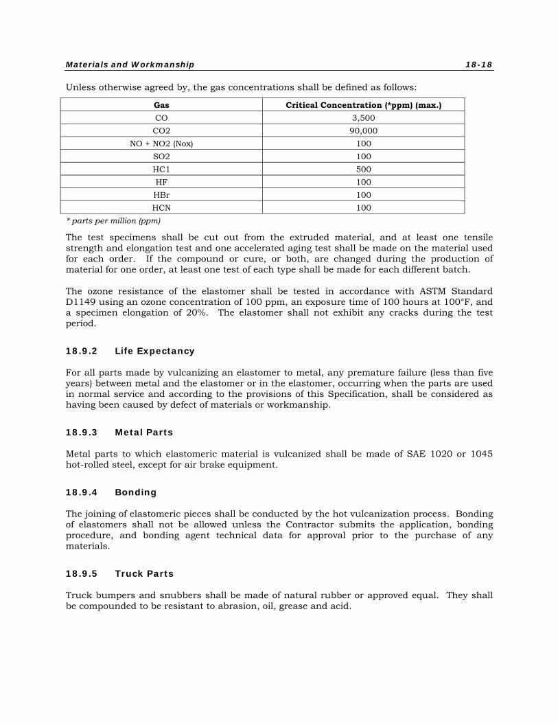
Unless otherwise agreed by, the gas concentrations shall be defined as follows:
Gas Critical Concentration (*ppm) (max.) CO 3,500 CO2 90,000
NO + NO2 (Nox) 100 SO2 100 HC1 500 HF 100 HBr 100 HCN 100
* parts per million (ppm)
The test specimens shall be cut out from the extruded material, and at least one tensile strength and elongation test and one accelerated aging test shall be made on the material used for each order. If the compound or cure, or both, are changed during the production of material for one order, at least one test of each type shall be made for each different batch.
The ozone resistance of the elastomer shall be tested in accordance with ASTM Standard D1149 using an ozone concentration of 100 ppm, an exposure time of 100 hours at 100°F, and a specimen elongation of 20%. The elastomer shall not exhibit any cracks during the test period.
18.9.2 Life Expectancy
For all parts made by vulcanizing an elastomer to metal, any premature failure (less than five years) between metal and the elastomer or in the elastomer, occurring when the parts are used in normal service and according to the provisions of this Specification, shall be considered as having been caused by defect of materials or workmanship.
18.9.3 Metal Parts
Metal parts to which elastomeric material is vulcanized shall be made of SAE 1020 or 1045 hot-rolled steel, except for air brake equipment.
18.9.4 Bonding
The joining of elastomeric pieces shall be conducted by the hot vulcanization process. Bonding of elastomers shall not be allowed unless the Contractor submits the application, bonding procedure, and bonding agent technical data for approval prior to the purchase of any materials.
18.9.5 Truck Parts
Truck bumpers and snubbers shall be made of natural rubber or approved equal. They shall be compounded to be resistant to abrasion, oil, grease and acid.
Materials and Workmanship 18-19
18.9.6 Glazing Strips
Glazing strips shall be of neoprene conforming to ASTM Standard C542-05, or of Styrene-Butadiene rubber. The compounding of the rubber shall be such as to preclude discoloration or staining of neighboring areas, particularly from water drainage.
Window glazing sections shall be service proven and constructed of high-quality elastomeric compounds containing neoprene subject to approval by the Customer. Glazing strips and other elastomeric extrusions shall be continuous and made from neoprene or other compounds suitable for the purpose and shall be free of major defects of material or workmanship.
18.10 Glazing Materials
All window glass shall be provided with tints, screens, or other solar/thermal limiting measures as required by the Heating, Ventilation and Air Conditioning (HVAC) design. The tints shall not preclude passengers from being seen from outside the car or limit their vision when looking out the bodyside windows.
Glazing used shall meet the following material criteria:
• Windshield glazing shall be a single-glaze, certified FRA Type I clear laminated safety glass, meeting all the applicable requirements of ANSI Standard Z-26.1 and U.S. Code of Federal Regulations, 49CFR Part 223, including Appendix A. The glazing shall incorporate an anti-spall shield on the interior side. The glazing shall be clear tint. The glazing shall be a minimum of 0.560-in. thick. The glazing’s maximum solar energy transmittance shall not exceed 70%.
• End door window glazing shall be a single-glaze, certified FRA Type I clear laminated safety glass, meeting all the applicable requirement of ANSI Z-26.1 and U.S. Code of Federal Regulations, 49CFR Part 223, including Appendix A. The glazing shall be clear tint. The glazing shall be 0.560-inch thick. The glazing maximum solar energy transmittance shall not exceed 90%.
• Side door window glazing shall be a single-glaze, certified FRA Type II clear laminated safety glass, meeting all applicable requirements of ANSI Z-26.1 and U.S. Code of Federal Regulations 49CFR Part 223, including Appendix A. The glazing shall be clear tint. The glazing shall be 0.375 inch thick. The glazing’s maximum solar energy transmittance shall not exceed 90%.
• Cab car control station sliding window assemblies shall be double-glazed. The outer pane shall be 0.250-inch thick, clear laminated safety glass. The inner pane shall be 0.250-inch thick, clear laminated safety glass. The double-glazed assembly shall have a 0.250-inch thick clear air space separating the inner and outer panes. The double-glazed assembly shall be certified FRA Type II and meet all the applicable requirements of ANSI Z-26.1 and U.S. Code of Federal Regulations, 49CFR Part 223, including Appendix A. The double-glazed assembly shall be clear tint. The double-glazed assembly’s maximum solar energy transmittance shall not exceed 85%.
• Side (non-emergency) window assemblies (emergency and non-emergency) shall be double-glazed. The outer pane shall be 0.250-inch thick, gray-tinted tempered safety glass unless specified otherwise by the Customer. The inner pane shall be 0.375-inch thick, clear tempered safety glass. The double-glazed assembly shall have a 0.375-inch dead air space separating the inner and outer panes. The double-glazed assembly shall be certified FRA Type II and meet all the applicable requirements of ANSI Z-26.1 and
Materials and Workmanship 18-20
U.S. Code of Federal Regulations, 49CFR Part 223, including Appendix A. The double-glazed assembly shall be a gray tint unless specified otherwise by the Customer. The double-glazed assembly’s visible light transmission shall be 24%. The double-glazed assembly’s maximum solar energy transmittance shall not exceed 50%.
18.10.1 Flatness
When an individual window of glass is laid on a truly flat surface, such as a surface plate, the glass shall not indicate a bow of more than 0.030 inch per linear foot.
18.10.2 Dimensional Tolerance
The overall dimensions of any window supplied shall not exceed ± 0.060 in. dimensional deviation.
18.10.3 Overlap Tolerance
The overlap of one laminate of the window with respect to the other at an edge shall not exceed 0.03125 in. Corners and burrs shall be ground smooth and all edges shall be treated in accordance with SAE Z26.1, Section 6.
18.10.4 Color
When new, there shall be no more than ± 4% variation in the color of individual windows of laminated sheet glass when examined over a white background.
18.10.5 Haze
All the laminates of the safety glass shall be so nearly free from haze that the laminated glass shall have approximately the same clarity as non-laminated plate glass of the same nominal thickness of plate glass.
18.10.6 Specks and Scratches
Occasional specks of foreign material and scratches are permissible, provided such specks do not exceed 0.020 in. in greatest dimension and scratches do not exceed a total of 3 in. in length and neither are within the central three-quarters area of the window. The Customer reserves the right to determine which windows are to be rejected.
The visual inspection criteria for laminated glazing shall be submitted for a Customer approval as part of the glazing design review.
18.10.7 Bond Separation
The bond between two sheets of glass and the membrane shall be of such quality that when the glass is broken by twisting or by direct impact, there will be no separation between the glass sheets. Windows that contain un-bonded areas shall not be used.
Materials and Workmanship 18-21
18.10.8 Marking
All safety glass shall be marked with proper identification in accordance with FRA 49CFR Part 223 requirements. The window shall be installed so that the identification marking can be read from the inside lower right hand corner.
Each window shall be marked for identification by the supplier in legible letters 0.125 in. to 0.25 in. high in the lower right hand corner as viewed from the inside of the vehicle. This identification shall be no closer than 0.375 in. to the edge. The identification shall give the product name, the manufacturer, the serial number and FRA Type designation. Markings shall be legible and permanent for this application and shall be applied in such a manner so as not to reduce the integrity of the coating. Markings are to be in accordance with 49CFR Part 223. The window shall be installed so that the identification can be read from the inside.
18.10.9 Shipping
The material shall be carefully prepared for shipping and shall be properly protected to prevent damage. If a pressure sensitive masking is used, it shall be easily strippable from the material and not leave a gummy or sticky residue.
18.11 Rubber Floor Covering
The floor covering shall be rubber sheet or approved equal. The covering shall meet ADA visibility and coefficient of friction requirements, with a static coefficient of friction of at least 0.6 on level surfaces and 0.8 on ramps, even when wet. Rubber floor covering shall contain 20% (nominal, by weight of compound) butadiene styrene rubber, shall be non-staining, non-discoloring, and 100% non-oil extended. Only high quality hard clay shall be used as filler. No whitening (limestone) shall be used in the compound. At room temperature, the rubber flooring shall bend around a 0.75 in. (19 mm) diameter mandrel without breaking, cracking, crazing or showing any change in color. The rubber flooring material shall be fully homogeneous throughout, and shall meet the requirements of ASTM F1344-04. Rubber flooring shall conform to the criteria below.
18.11.1 Thin Skinned Blister
A thin skinned blister is a blister, which when finger-pushed, will collapse upon itself. Thin skin blisters of the indicated sizes will be permitted as follows and shall be repaired as indicated:
• Maximum Size - 0.030 in. (0.8 mm) height, 0.80 in.2 (5.2 cm2) area with longest dimension of 2 in. (51 mm).
• Maximum Population - 3 blisters in a 12 in. (30.5 cm) by 12 in. (30.5 cm) area, and there shall be only one other blister within 3 ft (0.91 m) of this area.
• Repair Method - using a hypodermic needle, apply just enough Super Bond 420 or Bostik 1685 to bring to a flush surface.
Materials and Workmanship 18-22
18.11.2 Thick Skinned Blister
A thick skinned blister is a blister, which when finger-pushed, will collapse and then return to its original condition. Thick skin blisters of the indicated sizes will be permitted as follows and shall be repaired as indicated:
• Maximum Size - 0.030 in. (0.8 mm) height, 0.80 in.2 (5.2 cm2) area with longest dimension of 2 in. (51 mm).
• Maximum Population - 3 blisters in a 12 in. (30.5 cm) by 12 in. (30.5 cm) area, and there shall be only one other blister within 3 ft (0.91 m) of this area.
• Repair Method - no repair authorized.
18.11.3 Lumps
A lump is a blister without a void, consisting of solid material. Lumps of the indicated sizes will be permitted as follows and shall be repaired as indicated:
• Maximum Size - 0.030 in. (0.8 mm) height, 0.80 in.2 (5.2 cm2) area with longest dimension of 2 in. (51 mm).
• Maximum Population - 3 lumps in a 12 in. (30.5 cm) by 12 in. (30.5 cm) area, and there shall be only one other lump within 3 ft (0.91 m) of this area.
• Repair Method - no repair required.
18.11.4 Holes
A hole is a defect, which is 100% through the material. Holes of any size or population will not be permitted nor shall holes be repaired.
18.11.5 Thin Area
A thin area is a defect where the sheet is below thickness locally. Thin areas of the indicated sizes will be permitted as follows and shall be repaired as indicated:
• Maximum Size - 0.030 in. (0.8 mm) deep at the lowest point, 3 in.2 (19.4 cm2) area with the longest dimension of 5 in. (127 mm).
• Maximum Population - one thin area in a 40 in. (1 m) by 40 in. (1 m) area, and there shall not be another thin area within 3 ft (0.91 m) of this area.
• Repair Method - rub with #00 steel wool to blend this area into the normal thickness material and then buff to a normal surface finish.
18.11.6 Color and Marbling Distribution
Tolerances for color and marbling variation shall be submitted to the Customer for approval during preliminary design review. If the base coloring is not within 5% between production runs, or the marbling is not consistent over the entire surface, the roll shall be rejected.
Materials and Workmanship 18-23
18.12 Lumber and Paneling
18.12.1 Lumber
Lumber shall be thoroughly air seasoned or kiln dried before using and shall be dressed on all surfaces to full dimensions and treated to meet the testing requirements of Chapter 19. Lumber shall be straight grained, free from dry rot, knots checks and other defects which may impair its strength and durability or mar its appearance.
Except where specified, the use of wood in the car shall be limited to specifically approved applications.
Melamine shall be pressure bonded to marine grade plywood using industry approved adhesives. No contact bonding of melamine to plywood is permitted.
The term "cored panels" means honeycomb panels bonded to melamine or to metal faced hard-board (similar to Metalcomb, as marketed by Cored Panels, Inc., Farmingdale, New York).
Such panels must comply with United States Department of Agriculture Forest Products Laboratory Report No. 1937, Shear-Fatigue Properties of Various Sandwich Construction.
18.12.2 Plymetal
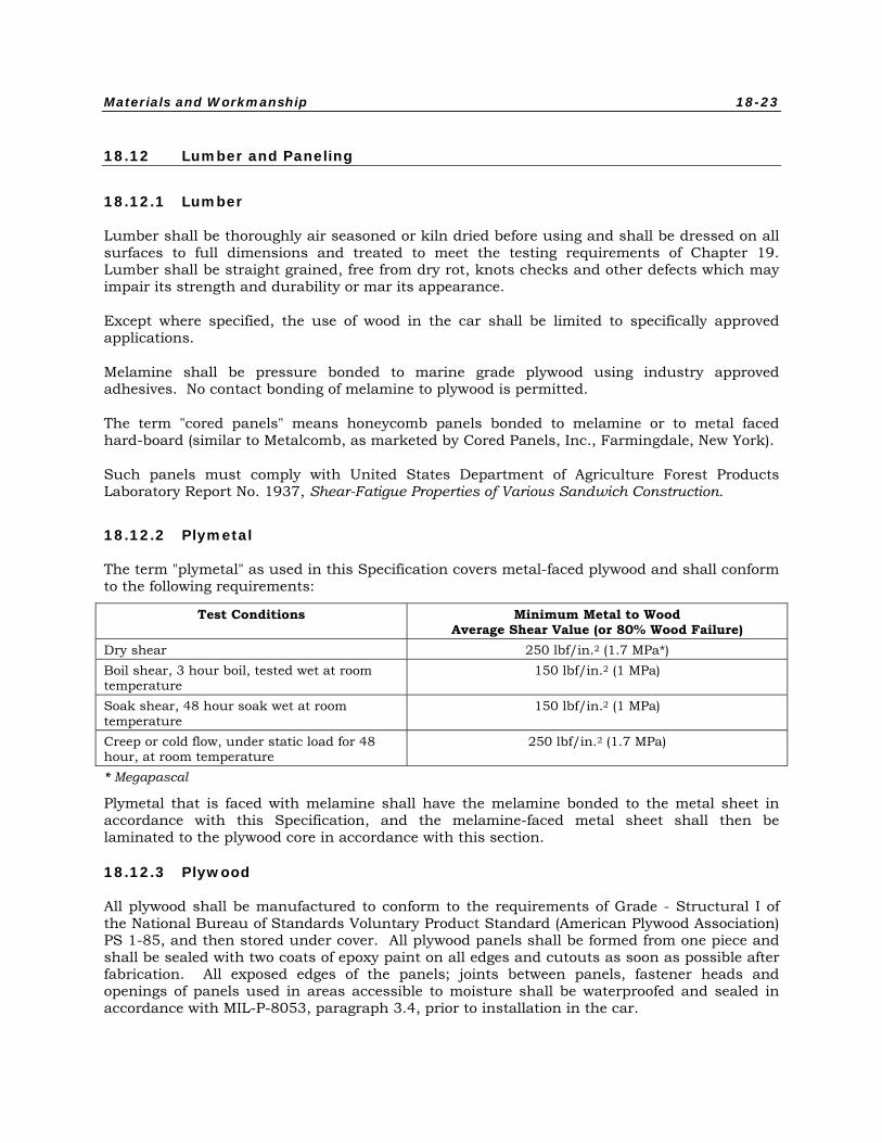
The term "plymetal" as used in this Specification covers metal-faced plywood and shall conform to the following requirements:
Test Conditions Minimum Metal to Wood Average Shear Value (or 80% Wood Failure)
Dry shear 250 lbf/in.2 (1.7 MPa*) Boil shear, 3 hour boil, tested wet at room temperature
150 lbf/in.2 (1 MPa)
Soak shear, 48 hour soak wet at room temperature
150 lbf/in.2 (1 MPa)
Creep or cold flow, under static load for 48 hour, at room temperature
250 lbf/in.2 (1.7 MPa)
* Megapascal
Plymetal that is faced with melamine shall have the melamine bonded to the metal sheet in accordance with this Specification, and the melamine-faced metal sheet shall then be laminated to the plywood core in accordance with this section.
18.12.3 Plywood
All plywood shall be manufactured to conform to the requirements of Grade - Structural I of the National Bureau of Standards Voluntary Product Standard (American Plywood Association) PS 1-85, and then stored under cover. All plywood panels shall be formed from one piece and shall be sealed with two coats of epoxy paint on all edges and cutouts as soon as possible after fabrication. All exposed edges of the panels; joints between panels, fastener heads and openings of panels used in areas accessible to moisture shall be waterproofed and sealed in accordance with MIL-P-8053, paragraph 3.4, prior to installation in the car.
Materials and Workmanship 18-24
18.12.4 Honeycomb Panels
The term "honeycomb panels" as used in this Specification refers to an assembly of honeycomb material bonded to melamine-faced metal panels or to metal panels. Aluminum honeycomb material shall be commercial-grade meeting the requirements of MIL-C-7438G. Bonding shall be sufficient to develop the full strength of the honeycomb material. Stainless steel honeycomb panels shall be constructed in accordance with the requirements of MIL-A- 9067C. The adhesive bond strength of the honeycomb core to the stainless steel face shall not be less than 15 lb/in. (2.68 kg/cm) climbing drum strength when tested in accordance with SAE-AMS-STD-401. The adhesive bond strength of the integral stainless frame to stainless steel face shall not be less than 30 lb/in (13.6 kg/2.5 cm) climbing drum strength when tested in accordance with SAE-AMS-STD-401. Stainless steel honeycomb panels shall be tested in accordance with SAE-AMS-STD-401 to demonstrate the following requirements. Test results shall be subject to Customer review and approval. CDRL
• Core shear yield at 200°F (93°C) 250 lbf/in.2 [1.72 Megapascal (MPa)]
• Flatwise tension at 200°F (93°C) 250 lbf/in.2 (1.72 MPa)
• Beam flexure at 200°F (93°C) 75,000 lbf/in.2 (517.13 MPa)
• Core shear fatigue at R.T. 150 lbf/in.2 @ 106 cycles (1.03 MPa)
• Flatwise tension at R.T. 250 lbf/in.2 @ 106 cycles (1.72 MPa)
• Beam flexure at R.T. 50,000 lbf/in.2 @ 106 cycles (344.75 MPa)
Honeycomb panels meet the relevant flammability and smoke emission requirements. Results shall be subject to Customer review and approval. No other honeycomb materials will be permitted. CDRL
18.12.5 Melamine-Faced Aluminum
Melamine-faced aluminum panels shall be constructed by laminating melamine to aluminum sheets as follows: The melamine impregnated papers shall be directly molded to the aluminum sheets at temperatures of no less than 270°F (132°C) and pressure no less than 1000 psi (6.9 MPa). The surface characteristics, after manufacture, shall be no less than that required of type GP (General Purpose) in the NEMA Standards Publication No. LD-3-2005, or latest revision. The melamine and the required binder sheets shall be 0.020 ± 0.005 in. (0.51 ± 0.13 mm) thick. The aluminum sheets shall not be less than 0.025 in. (0.64 mm) in thickness when used as a facing on plywood. The aluminum sheets shall not be less than 0.081 in. (2.1 mm) in thickness when not laminated to a substrate such as plywood. Aluminum sheets shall be properly cleaned by etching, sanding or other approved process to insure full, permanent, acceptable adhesion.
Materials and Workmanship 18-25
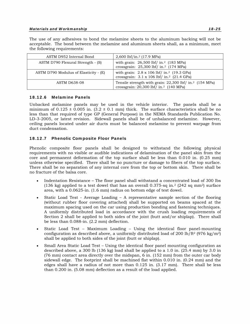
The use of any adhesives to bond the melamine sheets to the aluminum backing will not be acceptable. The bond between the melamine and aluminum sheets shall, as a minimum, meet the following requirements:
ASTM D952 Internal Bond 2,600 lbf/in.2 (17.9 MPa) ASTM D790 Flexural Strength - (S) with grain: 26,500 lbf/ in.2 (183 MPa)
crossgrain: 25,300 lbf/ in.2 (174 MPa) ASTM D790 Modulus of Elasticity - (E) with grain: 2.8 x 10⁶ lbf/ in.2 (19.3 GPa)
crossgrain: 3.1 x 10⁶ lbf/ in.2 (21.4 GPa) ASTM D638-08 Tensile strength with grain: 22,300 lbf/ in.2 (154 MPa)
crossgrain: 20,300 lbf/ in.2 (140 MPa)
18.12.6 Melamine Panels
Unbacked melamine panels may be used in the vehicle interior. The panels shall be a minimum of 0.125 ± 0.005 in. (3.2 ± 0.1 mm) thick. The surface characteristics shall be no less than that required of type GP (General Purpose) in the NEMA Standards Publication No. LD-3-2005, or latest revision. Sidewall panels shall be of unbalanced melamine. However, ceiling panels located under air ducts must be balanced melamine to prevent warpage from duct condensation.
18.12.7 Phenolic Composite Floor Panels
Phenolic composite floor panels shall be designed to withstand the following physical requirements with no visible or audible indications of delamination of the panel skin from the core and permanent deformation of the top surface shall be less than 0.010 in. (0.25 mm) unless otherwise specified. There shall be no puncture or damage to fibers of the top surface. There shall be no separation of any internal core from the top or bottom skin. There shall be no fracture of the balsa core.
• Indentation Resistance – The floor panel shall withstand a concentrated load of 300 lbs (136 kg) applied to a test dowel that has an overall 0.375-sq in.2 (242 sq mm2) surface area, with a 0.0625-in. (1.6 mm) radius on bottom edge of test dowel.
• Static Load Test - Average Loading – A representative sample section of the flooring (without rubber floor covering attached) shall be supported on beams spaced at the maximum spacing used on the car using production bonding and fastening techniques. A uniformly distributed load in accordance with the crush loading requirements of Section 2 shall be applied to both sides of the joint (butt and/or shiplap). There shall be less than 0.088-in. (2.2 mm) deflection.
• Static Load Test – Maximum Loading – Using the identical floor panel-mounting configuration as described above, a uniformly distributed load of 200 lb/ft2 (976 kg/m2) shall be applied to both sides of the joint (butt or shiplap).
• Small Area Static Load Test – Using the identical floor panel mounting configuration as described above, a 300 lb (136 kg) load shall be applied to a 1.0 in. (25.4 mm) by 3.0 in (76 mm) contact area directly over the midspan, 6 in. (152 mm) from the outer car body sidewall edge. The footprint shall be machined flat within 0.010 in. (0.24 mm) and the edges shall have a radius of not more than 0.125 in. (3.17 mm). There shall be less than 0.200 in. (5.08 mm) deflection as a result of the load applied.
Materials and Workmanship 18-26
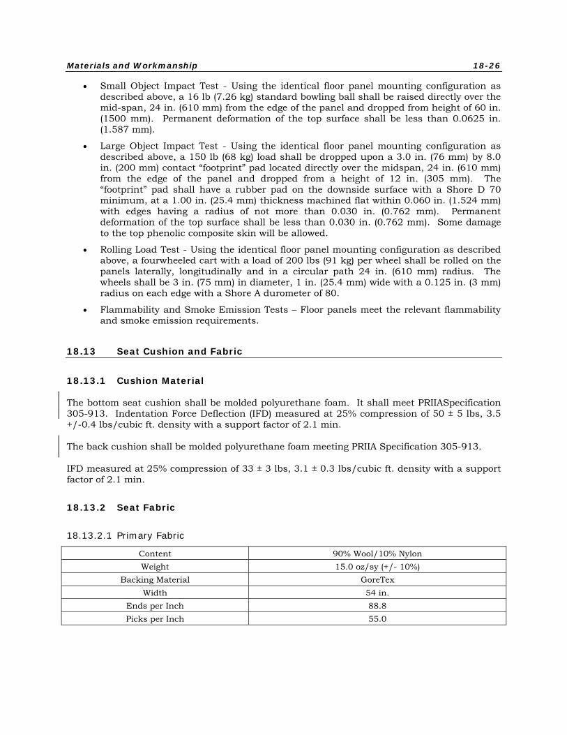
• Small Object Impact Test - Using the identical floor panel mounting configuration as described above, a 16 lb (7.26 kg) standard bowling ball shall be raised directly over the mid-span, 24 in. (610 mm) from the edge of the panel and dropped from height of 60 in. (1500 mm). Permanent deformation of the top surface shall be less than 0.0625 in. (1.587 mm).
• Large Object Impact Test - Using the identical floor panel mounting configuration as described above, a 150 lb (68 kg) load shall be dropped upon a 3.0 in. (76 mm) by 8.0 in. (200 mm) contact “footprint” pad located directly over the midspan, 24 in. (610 mm) from the edge of the panel and dropped from a height of 12 in. (305 mm). The “footprint” pad shall have a rubber pad on the downside surface with a Shore D 70 minimum, at a 1.00 in. (25.4 mm) thickness machined flat within 0.060 in. (1.524 mm) with edges having a radius of not more than 0.030 in. (0.762 mm). Permanent deformation of the top surface shall be less than 0.030 in. (0.762 mm). Some damage to the top phenolic composite skin will be allowed.
• Rolling Load Test - Using the identical floor panel mounting configuration as described above, a fourwheeled cart with a load of 200 lbs (91 kg) per wheel shall be rolled on the panels laterally, longitudinally and in a circular path 24 in. (610 mm) radius. The wheels shall be 3 in. (75 mm) in diameter, 1 in. (25.4 mm) wide with a 0.125 in. (3 mm) radius on each edge with a Shore A durometer of 80.
• Flammability and Smoke Emission Tests – Floor panels meet the relevant flammability and smoke emission requirements.
18.13 Seat Cushion and Fabric
18.13.1 Cushion Material
The bottom seat cushion shall be molded polyurethane foam. It shall meet PRIIASpecification 305-913. Indentation Force Deflection (IFD) measured at 25% compression of 50 ± 5 lbs, 3.5 +/-0.4 lbs/cubic ft. density with a support factor of 2.1 min.
The back cushion shall be molded polyurethane foam meeting PRIIA Specification 305-913.
IFD measured at 25% compression of 33 ± 3 lbs, 3.1 ± 0.3 lbs/cubic ft. density with a support factor of 2.1 min.
18.13.2 Seat Fabric
18.13.2.1 Primary Fabric
Content 90% Wool/10% Nylon Weight 15.0 oz/sy (+/- 10%)
Backing Material GoreTex Width 54 in.
Ends per Inch 88.8 Picks per Inch 55.0
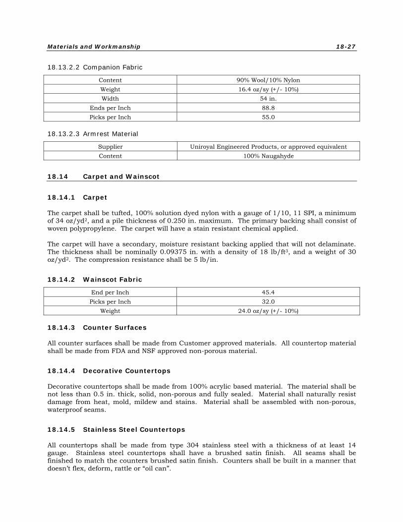
Materials and Workmanship 18-27
18.13.2.2 Companion Fabric
Content 90% Wool/10% Nylon Weight 16.4 oz/sy (+/- 10%) Width 54 in.
Ends per Inch 88.8 Picks per Inch 55.0
18.13.2.3 Armrest Material
Supplier Uniroyal Engineered Products, or approved equivalent Content 100% Naugahyde
18.14 Carpet and Wainscot
18.14.1 Carpet
The carpet shall be tufted, 100% solution dyed nylon with a gauge of 1/10, 11 SPI, a minimum of 34 oz/yd2, and a pile thickness of 0.250 in. maximum. The primary backing shall consist of woven polypropylene. The carpet will have a stain resistant chemical applied.
The carpet will have a secondary, moisture resistant backing applied that will not delaminate. The thickness shall be nominally 0.09375 in. with a density of 18 lb/ft3, and a weight of 30 oz/yd2. The compression resistance shall be 5 lb/in.
18.14.2 Wainscot Fabric
End per Inch 45.4 Picks per Inch 32.0
Weight 24.0 oz/sy (+/- 10%)
18.14.3 Counter Surfaces
All counter surfaces shall be made from Customer approved materials. All countertop material shall be made from FDA and NSF approved non-porous material.
18.14.4 Decorative Countertops
Decorative countertops shall be made from 100% acrylic based material. The material shall be not less than 0.5 in. thick, solid, non-porous and fully sealed. Material shall naturally resist damage from heat, mold, mildew and stains. Material shall be assembled with non-porous, waterproof seams.
18.14.5 Stainless Steel Countertops
All countertops shall be made from type 304 stainless steel with a thickness of at least 14 gauge. Stainless steel countertops shall have a brushed satin finish. All seams shall be finished to match the counters brushed satin finish. Counters shall be built in a manner that doesn’t flex, deform, rattle or “oil can”.
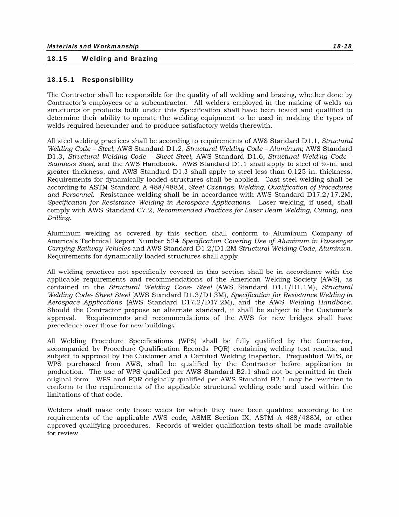
Materials and Workmanship 18-28
18.15 Welding and Brazing
18.15.1 Responsibility
The Contractor shall be responsible for the quality of all welding and brazing, whether done by Contractor’s employees or a subcontractor. All welders employed in the making of welds on structures or products built under this Specification shall have been tested and qualified to determine their ability to operate the welding equipment to be used in making the types of welds required hereunder and to produce satisfactory welds therewith.
All steel welding practices shall be according to requirements of AWS Standard D1.1, Structural Welding Code – Steel; AWS Standard D1.2, Structural Welding Code – Aluminum; AWS Standard D1.3, Structural Welding Code – Sheet Steel, AWS Standard D1.6, Structural Welding Code – Stainless Steel, and the AWS Handbook. AWS Standard D1.1 shall apply to steel of ⅛-in. and greater thickness, and AWS Standard D1.3 shall apply to steel less than 0.125 in. thickness. Requirements for dynamically loaded structures shall be applied. Cast steel welding shall be according to ASTM Standard A 488/488M, Steel Castings, Welding, Qualification of Procedures and Personnel. Resistance welding shall be in accordance with AWS Standard D17.2/17.2M, Specification for Resistance Welding in Aerospace Applications. Laser welding, if used, shall comply with AWS Standard C7.2, Recommended Practices for Laser Beam Welding, Cutting, and Drilling.
Aluminum welding as covered by this section shall conform to Aluminum Company of America's Technical Report Number 524 Specification Covering Use of Aluminum in Passenger Carrying Railway Vehicles and AWS Standard D1.2/D1.2M Structural Welding Code, Aluminum. Requirements for dynamically loaded structures shall apply.
All welding practices not specifically covered in this section shall be in accordance with the applicable requirements and recommendations of the American Welding Society (AWS), as contained in the Structural Welding Code- Steel (AWS Standard D1.1/D1.1M), Structural Welding Code- Sheet Steel (AWS Standard D1.3/D1.3M), Specification for Resistance Welding in Aerospace Applications (AWS Standard D17.2/D17.2M), and the AWS Welding Handbook. Should the Contractor propose an alternate standard, it shall be subject to the Customer’s approval. Requirements and recommendations of the AWS for new bridges shall have precedence over those for new buildings.
All Welding Procedure Specifications (WPS) shall be fully qualified by the Contractor, accompanied by Procedure Qualification Records (PQR) containing welding test results, and subject to approval by the Customer and a Certified Welding Inspector. Prequalified WPS, or WPS purchased from AWS, shall be qualified by the Contractor before application to production. The use of WPS qualified per AWS Standard B2.1 shall not be permitted in their original form. WPS and PQR originally qualified per AWS Standard B2.1 may be rewritten to conform to the requirements of the applicable structural welding code and used within the limitations of that code.
Welders shall make only those welds for which they have been qualified according to the requirements of the applicable AWS code, ASME Section IX, ASTM A 488/488M, or other approved qualifying procedures. Records of welder qualification tests shall be made available for review.
Materials and Workmanship 18-29
18.15.2 Test Welds
The Customer shall have the right to require an operator to make test welds to determine his/her ability to produce satisfactory welds of any given type. The Customer shall also have the right to require the making of test welds to settle any question that shall arise as to the suitability of any welding method or procedure used during production. The recommendations of the AWS shall be followed in the making of tests and the settlement of other questions that may arise hereunder regarding welding practice.
Weld heat-affected zones (HAZ) and weld metal shall be limited to maximum allowable stress values in ASME Section VIII, Table UHA-23, for UNS S20100 stainless steel and Table UW-12 rating of welds.
Fatigue allowable stresses shall not exceed the lesser of fatigue limits in AWS Standard D1.1, Section 2.20.6, or 50% of the joint strength level calculated from ASME maximum allowable stress values. Higher values shall only be used if qualified by Contractor tests
18.15.3 Cleaning
Prior to welding, parts to be joined shall be properly cleaned of coatings and films such as rust, oxide, mill scale, oil, grease, corrosion products, and other foreign materials. Cleaning materials and processes shall be in accordance with applicable parts of Section 2, MIL-HDBK-132, Protective Finishes. Finished welds shall present a clean appearance.
18.15.4 Support
All parts which shall be joined by welding shall be adequately supported during welding by tables, jigs or fixtures.
18.15.5 Welding Rod
All welding rod, wire, electrodes or filler metal; shall be chosen by the Contractor or subcontractor with respect to manufacturer, type and size necessary to achieve the highest quality work. The Contractor shall have full responsibility for the character of the work produced. It shall be purchased in packages of convenient size, which shall be marked with the Manufacturer's name and the specification, diameter, and net weight of the material.
The material shall be stored in accordance with recommendations of the AWS Structural Welding Code so as to protect it from damage, and so that it shall be easily identified. Material shall be issued and handled in such a way as to prevent it from being mixed with that of another specification.
The ferrite number for austenitic stainless steel welds shall be between WRC4 and WRC10, or as proposed by the Contractor and approved by the Customer.
In case a question arises regarding the suitability of welding rod, wire, electrodes or filler metal, the provisions of AWS Standard D1.1/D1.1M shall govern.
Materials and Workmanship 18-30
18.15.6 Control
Current, voltage, distance, flame and other variables shall be so controlled as to give a smooth weld, free of gas pockets, oxide inclusions, variations in width and thickness, wandering and spattering.
18.15.7 Penetration
Penetration of weld metal into the bottoms of angles and vees and fusion, shall be complete. Weld metal shall run into the base metal at the finished surface of the weld in a smooth curve approximately tangent to the surfaces of the base metal so as to avoid sudden change of section and resultant concentration of stress. Undercutting shall not exceed 10% of the thickness of the thinnest element, or 0.030 in., whichever is less.
18.15.8 Warpage
The method of depositing weld metal shall be chosen so as to minimize warpage and locked-up stresses. Tack welding, skip welding, offset welding and other comparable procedures shall be used for this purpose.
18.15.9 Intermittent Weld Spacing
Intermittent fusion-weld spacing pitch shall not exceed 5 in. for 2-in. (minimum) weld lengths, such that a minimum weld length of 40% of the overall joint length is achieved.
18.15.10 Fusion Welding
Manual fusion welding by the gas process may only be used on sheets more than 0.09375 in. in thickness. Any other application of this process must be approved by the Customer.
18.15.11 Resistance Welding
Resistance welding shall be in accordance with AWS Standard D17.2/D17.2M Class B for structural applications and Class C for non-structural applications. Stainless steel parts shall be joined, insofar as possible, by resistance welding. This procedure shall employ accurate control of current, time, electrode size and shape, and tip force, to produce uniform welds of specified strength which shall not be subject to surface corrosion. Resistance welds in materials other than austenitic stainless steel shall be arranged to avoid tension or "peeling" forces on the welds under any anticipated loading condition.
Sample resistance welds in all materials shall be made with calculated settings of current, time and tip pressure, static (pull) tested and, in the case of austenitic stainless steel elements, chisel tested to verify adequacy; and a record shall be made which includes the settings and ultimate shear strength. (A chisel test shall be made by inserting a chisel between two resistance-welded plates to verify that a weld nugget shall be pulled out of one of the plates). Sample welds shall be made and tested at the beginning of each shift and, in addition,
Materials and Workmanship 18-31
whenever there shall be a change in any of the following:
• Operator
• Material, material thickness, or combination of thicknesses
• Electrodes
• Settings
Spacing of resistance and spot welds shall be appropriate to the design. Spacing shall not exceed 2 in. plus twice the weld nugget diameter for any structural application, including car body side sheets. For any corrugation application, if the pitch of the corrugation nodes does not allow the above weld spacing, there shall be two spot welds between each node.
Surface indentation shall not exceed 20% of material thickness (t) or 0.01 in., whichever is greater. However, for exterior resistance-welded areas exposed to passenger view, indentation shall not exceed 10% of material thickness or 0.005 in., whichever is greater. For exposed welds, the Contractor shall vary welding parameters and conditions within their acceptable ranges to minimize indentations. Surface burn and discoloration shall be removed by chemical cleaning, or an approved equal method, and sanding or polishing to match the surrounding surface.
18.15.12 Special Welding
Procedures for structural welding of stainless steel to HSLA, or other combinations of metals or conditions not covered by AWS specifications or codes, shall be submitted for approval.
Austenitic stainless steel electrodes or wire shall be used to join carbon or HSLA steels to stainless steels.
For the application of welding processes not addressed in other parts of this specification, the Contractor shall submit equipment qualifications, procedure qualification records, and welding procedure specifications either conforming to identified industry standards or consistent with the approach of AWS Standard D17.2/17.2M, Specification for Resistance Welding in Aerospace Applications.
Standards that may apply to selected processes include:
• AWS Standard D17.3/D17.3M, Specification for Friction Stir Welding of Aluminum Alloys for Aerospace Applications.
• ANSI/AWS Standard C7.2, Recommended Practices for Laser Beam Welding, Cutting, and Drilling.
• ANSI/AWS Standard C7.4/C7.4M, Process Specification and Operator for Laser Beam Welding.
• ISO/DIS Standard 15609-4, Specification and Qualification of Welding Procedures for Metallic Materials - Welding Procedure Specification - Part 4: Laser Beam Welding.
Galvanized steel shall not be welded to stainless steel. Brazing shall not be used to join stainless steel to either stainless steel or to any other metals.
Materials and Workmanship 18-32
18.15.13 Toughness of Welded Assemblies
The Contractor shall prove all welded steel structures are above the ductile-brittle transition temperature for the specified environmental exposure. Specifically, the weld Heat-Affected Zone (HAZ) and base metal shall resist service impact loads at the lowest specified operating temperature without brittle failure. If the Contractor's approved design does not require greater toughness, the minimum impact value for Charpy V-notch specimens shall be 15 ft-lbf of absorbed energy at the lowest specified operating temperature. The Customer shall have the right to require impact tests to verify the specified toughness.
18.15.14 Torch Brazing
All brazing, characterized by heating above 840°F, shall follow the recommendations contained in the AWS Welding HandBook, Volume 2. Procedures and personnel who do brazing work shall be qualified in accordance with AWS Standard B2.2, Standard for Brazing Procedure and Performance Qualification.
18.15.15 Torch Soldering
All structural (not electrical) soldering, characterized by heating below 840ºF, shall follow the recommendations contained in the AWS Welding HandBook, Volume 2. Procedures and personnel who do torch soldering shall be qualified in accordance with AWS Standard B2.3/B2.3M, Specification for Soldering Procedure and Performance Qualification.
18.16 Exterior Marking Films and Graphics
Graphics shall be transportation grade materials, printed on opaque background with clear, vandal resistant overlayment. All graphics materials are to be approved by Customer. Application techniques shall be in accordance with manufacturer’s recommendations.
18.16.1 Physical Properties
• Shall be able to withstand long-term exposure to all environmental and operating conditions specified in PRIIA Specification 305-912.
• Lettering film shall be sufficiently opaque so that, when applied, films shall completely hide any contrasting background and shall be readily legible.
• There shall be an initial 60-degree gloss value of 40 when tested in accordance with ASTM Standard D523-08.
• Films shall retain adhesive properties after one week of continuous exposure to a temperature of 66°C (150°F).
• Films shall be able to conform to moderate contours of the vehicle’s interior and exterior surfaces at locations where decals are to be applied.
• Overall thickness of processed film shall be between 0.10 mm and 0.20 mm (0.004 and 0.008 in.).
• Films shall withstand immersion in either distilled water or SAE No. 20 motor oil for 24 hours at temperatures from 21°C to 32°C (70°F to 90°F) without any appreciable degradation in adhesion, color or general appearance.
Materials and Workmanship 18-33
• Marking films shall withstand effects of detergents and brushes used in washing procedures for removal of graffiti.
• Films shall use a removable grade adhesive that upon removal does not require use of solvents or secondary operations.
• Square or rectangular graphics shall have rounded corners of suitable radius.
18.17 Paints and Coatings
18.17.1 Materials and General Requirements
Painting of the car serves two primary purposes: 1) to protect the vehicle from corrosion and 2) to contribute to the overall aesthetic quality of the vehicle. Paint coatings should also assist in the overall maintenance of the vehicle by providing easy to clean surfaces. The vehicle must be fully and properly coated to achieve its service life with regular maintenance intervals
The surface preparation, primer, paint and graphics applications shall ensure that the car can operate at least eight years between major exterior finish repairs or replacement.
Preparation of the painted surface and application of painting materials for brushing or spraying shall be in accordance with the paint supplier's recommendations. Each coat shall be uniformly applied over all surfaces to be covered, and shall be free from runs, sags, or other application defects.
18.17.2 Paint Process Documentation
The Contractor shall prepare a paint coating and application document containing procedures for surface cleaning and preparation, priming, surfacing, and painting for the car body and all equipment that is painted or powder coated. A detailed paint schedule showing the equipment painted, paint type and manufacturers, recommended thickness, and other pertinent information shall also be included. This document shall be included in the maintenance manuals. It shall meet PRIIA Specifications 305-904 and 305-905.
18.17.3 Painting Restrictions
Any equipment or parts of equipment which would be damaged or suffer impaired operation from painting shall not be painted and shall be corrosion resistant.
The following items shall not be painted:
• Copper tubing, piping, and fittings
• Wire and cable
• Heat transfer surfaces
• Elastomeric portions of air and refrigerant lines
• Grounding pads and straps
• Wheels
• Axles
• Brake rotors
Materials and Workmanship 18-34
• Brake shoes and pads
• Air hoses
• Pedestal liners
• Elastomeric parts
• Grease fittings
• Linkages
• Threaded parts used for adjustments
• Electrical equipment
• Couplers
• Wearing surfaces
• Corrosion Protection
Concealed surfaces capable of rusting or oxidation shall be properly cleaned, then primed with a rust inhibiting paint, and painted with an approved finish coat of paint.
All exposed surfaces shall be suitably finished to prevent corrosion during storage and operation, in accordance with the following requirements:
• Areas exposed to dirt shall be designed to minimize retention of dirt and moisture, and sections that may retain moisture or dirt shall be provided with adequate drainage and ventilation and shall be accessible for cleaning. Under-pans or covers, suitable sealed, may be used where applicable to protect underframe sections.
• Joints and crevices shall be sealed with a polysulphide, butyl rubber, or equivalent sealant which is resistant to the operating environment, shall not absorb moisture and shall remain resilient and maintain its sealing properties for the life of the vehicle.
• Metal surfaces shall be treated with surface preparation and primer materials specific for the metal with due consideration for the severity of exposure to which the surface is subjected.
• Any corrosion protection removed for welding shall be replaced after welding is completed.
• Where arc welding is performed on joints between stainless steel and other materials.
18.18 Insulation
18.18.1 Acoustical Insulation
To reduce movement, structurally-borne sound and noise generated by the vibration of the roof, floor and side sheets, panels, air conditioning ducts and other metal surfaces, in particular the doors, damping material shall be applied to the inner side of these surfaces (exterior of the HVAC ducts).
Korfund Vibrodamper Compound, Aquaplas DL-10-HV or Customer approved equal shall be applied to the interior of the complete structural car shell including the roof, sides, floor, ends, webs of all posts, carlines, floor beams and other structural elements.
Materials and Workmanship 18-35
Application of this damping compound and the surfaces to which it shall be applied shall be in accordance with recommendations of the manufacturer of the compound. The thickness of the damping material shall be such that it provides 10% of critical damping for the treated surface.
18.18.2 Thermal Insulation
The roof, sides, under floor, and ends of the vehicles, including the inside faces of posts and structural members shall be fully insulated.
The density, thickness and type insulation shall be determined by U value requirements established by the HVAC calculations and shall be in accordance with the requirements of these Technical Provisions.
18.18.2.1 General
Insulation materials shall be rigid, nonrigid or spray-on type. Materials shall be non-absorptive of fluids and gases, self-extinguishing, and vermin-proof, and shall have the required properties to meet the noise, vibration and heat loss limits as specified herein.
All materials shall be graded and labeled as standard with the recognized industry associations or societies. Labels shall be permanently affixed to, or imprinted on, the packages or containers of the materials.
18.18.2.2 Installation
All insulation materials shall be installed in accordance with the Manufacturer’s recommendations. Rigid and non-rigid preformed insulation shall be secured with mechanical fasteners or fire-resistant adhesive, or both. Spray-on insulation shall be applied over surfaces free from dirt, grease and other contaminants that might affect the adherence of the material. Parts subject to corrosion shall be given required protection prior to applying the insulation. The Contractor shall take care to avoid thermal shorts in the insulation as installed.
18.18.2.3 Materials
The following materials are acceptable for use on the vehicle:
• Rigid insulation
• Glass fiber preformed board
• Non-rigid Insulation
• Spun glass fiber in flexible rolls or mineral wool batts
Materials and Workmanship 18-36
18.18.2.4 Insulation Performance
Insulation materials shall be certified to conform to the following requirements:
Property ASTM Test Method Requirement Flame Resistance
Glass Fiber Board E162 E662
Flame spread 25 max Ds(4.0) – 100 max
Non-rigid Insulation E162 E662
Flame spread 25 max Ds(4.0) – 100 max.
Spray-on Insulation E162 E662
Flame spread 25 max Ds(4.0) – 100 max.
Vapor Barrier Rating C353
Water Method 2.5 perm at 90°F [32°C] and 50% relative humidity
Note: A vapor transmission rate of one grain of water vapor per square foot per hour at a pressure difference of one inch of mercury is defined as one perm.
The thermal conductivity of insulation materials shall be certified when tested in accordance with ASTM C177-04 at 75°F [24°C] mean temperature.
Insulation separated by a vapor barrier shall be used under the floor. The underfloor insulation shall be protected by stainless steel sheathing, which shall seal the underside of the vehicle against water, dust and debris.
Floor insulation material shall be compatible with the material used at locations in the vehicle structure and shall not mold, rot, or sustain vermin.
18.19 Flammability and Smoke Emissions
The vehicle and its components shall comply with the requirements of 49CFR Section 238.103, Appendix B and APTA Recommended Practice RP-PS-005-00. Compliance of the materials with these requirements shall be fully documented with test reports and certificates. For test reports submitted from previously performed tests, the Contractor shall demonstrate that materials included in the test report are identical to the actual materials used on the construction of the vehicles. For high risk materials, test data from these reports shall be dated no more than five years old from the Contract award data and shall be submitted to the Customer for approval. For low risk materials, test date from these reports that are dated between five and 10 years old shall be accompanied by a letter from the manufacturer stating that the materials included in the test report are identical to the actual materials used in the construction of the vehicles. Materials deemed as low risk shall be approved by the Customer.
There are instances where the Specification calls for use of specific materials, such as Lexan, when it is known that they do not meet all requirements of this section. It is predetermined that use of materials defined by this Specification is acceptable.
A matrix showing the total weight of each combustible material, where used, supplier's name, flammability and smoke emission test identity, test facility, test requirements, test results, nature and quantity of the products of combustion, and heating value in Btu/lb and Btu/hr shall be submitted by the Contractor during detailed design review. CDRL
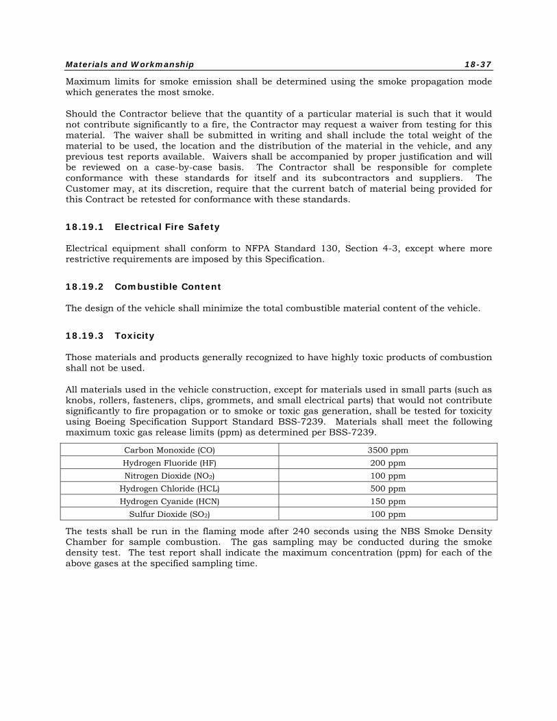
Materials and Workmanship 18-37
Maximum limits for smoke emission shall be determined using the smoke propagation mode which generates the most smoke.
Should the Contractor believe that the quantity of a particular material is such that it would not contribute significantly to a fire, the Contractor may request a waiver from testing for this material. The waiver shall be submitted in writing and shall include the total weight of the material to be used, the location and the distribution of the material in the vehicle, and any previous test reports available. Waivers shall be accompanied by proper justification and will be reviewed on a case-by-case basis. The Contractor shall be responsible for complete conformance with these standards for itself and its subcontractors and suppliers. The Customer may, at its discretion, require that the current batch of material being provided for this Contract be retested for conformance with these standards.
18.19.1 Electrical Fire Safety
Electrical equipment shall conform to NFPA Standard 130, Section 4-3, except where more restrictive requirements are imposed by this Specification.
18.19.2 Combustible Content
The design of the vehicle shall minimize the total combustible material content of the vehicle.
18.19.3 Toxicity
Those materials and products generally recognized to have highly toxic products of combustion shall not be used.
All materials used in the vehicle construction, except for materials used in small parts (such as knobs, rollers, fasteners, clips, grommets, and small electrical parts) that would not contribute significantly to fire propagation or to smoke or toxic gas generation, shall be tested for toxicity using Boeing Specification Support Standard BSS-7239. Materials shall meet the following maximum toxic gas release limits (ppm) as determined per BSS-7239.
Carbon Monoxide (CO) 3500 ppm Hydrogen Fluoride (HF) 200 ppm Nitrogen Dioxide (NO2) 100 ppm
Hydrogen Chloride (HCL) 500 ppm Hydrogen Cyanide (HCN) 150 ppm
Sulfur Dioxide (SO2) 100 ppm
The tests shall be run in the flaming mode after 240 seconds using the NBS Smoke Density Chamber for sample combustion. The gas sampling may be conducted during the smoke density test. The test report shall indicate the maximum concentration (ppm) for each of the above gases at the specified sampling time.
Materials and Workmanship 18-38
18.20 Piping
All piping shall be deburred and blown out after cutting or forming. After installation, the piping runs shall be cleaned using an approved method and procedure.
Piping shall be installed free of low spots to provide complete drainage away from control devices and to prevent damage by freezing. All piping shall be adequately clamped (clamps not welded to pipe) to prevent vibration, using an approved elastomeric tape between the clamp and the pipe. Copper tubing shall be sheathed at clamps or sheathed clamps shall be used. Piping through bulkheads or structure shall be positioned to avoid chafing the use of clamping and/or grommets.
All piping shall be installed using a minimum number of fittings. Unions shall be used only where necessary to permit replacement of apparatus. Hoses shall be provided with swivel type fittings to allow replacement without disturbing surrounding piping or apparatus.
18.20.1 Air Brake Piping and Fittings
Air brake tubing and piping shall be of good commercial quality, free of burrs and scale.
Car body air lines ½ inch nominal and smaller, and in protected locations, shall be of seamless copper tubing, in accordance with Federal Specification WW-T-799F, Type "K", with wrought copper or cast brass sweat type fittings in accordance with ANSI Standards B16.22 and B16.18, or stainless steel with stainless steel flare fittings.
All air piping on trucks and car body air lines larger than 0.5 in. nominal or where subjected to flying debris shall be black pipe conforming to ASTM Standard A53/A53M (schedule 80) with black malleable iron welded fittings, all painted the same as the underframe. Stainless steel pipe and welded stainless steel fittings may also be used. Bends in piping shall utilize large bend radii whenever possible to prevent restriction to the free flow of air. Threaded fittings may be used only where approved on a case-by-case basis. Malleable iron street ells or close nipples shall not be used, except at brake valve exhaust ports.
Hoses shall be allowed only to allow for coupler motion, gladhand connections and connections to brake cylinders from truck body piping. Truck piping shall employ a minimum number of fittings and hoses.
Brake system piping shall be installed in accordance with the recommendations of AAR Standard S-400. Brake piping shall have no low spots (traps) or any 45º or 90º elbows that form "doglegs" in piping runs. The highest point in the Brake Pipe shall be the branch pipe connection to the brake control unit.
Any piping or tubing which could be disconnected during servicing (event recorder air manifold, etc) shall be permanently labeled to enable the piping to be reconnected correctly when reassembled.
18.20.2 Air Conditioning and Refrigeration System Piping and Fittings
Air Conditioning and refrigeration refrigerant lines shall be fabricated using type K copper tubing and wrought copper sweat type fittings. This shall also apply to lines within supplier furnished apparatus except that finned tubing in evaporators and condensers need not be type
Materials and Workmanship 18-39
K. Instead of elbows, tubing may be bent by means of a tubing bending tool. All tubing shall be deburred after cutting.
Piping shall be routed to keep the number of bends to a minimum. All inaccessible runs of tubing shall be without joints. All suction lines and those subject to sweating shall be insulated. If necessary to limit transmitted noise and vibration to the carbody or to protect the refrigerant compressor from external vibrations, vibration isolators shall be used in the piping connections to the refrigerant compressor.
After fabrication, the system shall be cleared of all dirt and foreign matter using an approved procedure. The completed refrigeration system shall be evacuated and charged with refrigerant using a Customer-approved procedure.
The discharge of condensate drains lines shall be directly to the roadbed avoiding car structure, electrical cables and other undercar equipment.
18.20.3 Soldering of Piping and Fittings
Copper air brake and refrigerant tubing shall be continuously purged with an inert gas during joining and shall be joined using silver solder conforming to Federal Specification QQ-B-654A, BCuP-5, or BAg-5. Condensate drain tubing and car body air brake tubing shall be joined using silver solder. Soldered joints shall be wiped and the flux cleaned from the tubing and fittings after soldering.
18.20.4 Water Piping and Fittings
All water and waste system piping shall be seamless stainless steel tubing approved for water service applications. ASTM A269 or A312 austenitic stainless steel tube or other Engineer-approved materials shall be used, along with matching fittings. The use of copper waste system piping is expressly prohibited, due to extensive corrosion experienced in Amtrak service. All water systems being supplied shall comply with the design requirements of PRIIA Specification 305-902. All piping shall be clamped with necessary sound insulation to prevent rattle, and must be sloped to allow drainage.
If use of copper piping is approved by the Engineer for water supply applications, it shall be Type K drawn (H temper) seamless copper tube per ASTM B88. All joints for copper tubing shall utilize fittings of wrought copper in accordance with ANSI Standards B16.22 and B16.88, and shall be joined using silver solder.
After installation, the complete water system shall be sanitized. The sanitizing procedure shall be approved by the Customer.
The piping shall be routed and sloped to allow for proper drainage. Low points in piping shall be equipped with Ogontz or equivalent automatic drain valves (specified in respective Sections), each equipped with a heater, which shall discharge all the water in the vehicle to the tracks whenever the air temperature at the valve falls below 38ºF. This shall be demonstrated during the climate room testing described in Chapter 19. To insure complete drainage, venting valves shall be provided to operate in conjunction with the drain valves. At each automatic drain valve, a manual drain valve shall be piped in parallel. Sufficient manual drain valves shall be provided to allow complete draining of the car. Valves shall be labeled in accordance with PRIIA Specification 305-908.
Materials and Workmanship 18-40
Drains from the water system shall be routed to discharge directly onto the ground, avoiding car structure, electrical cables and all other undercar equipment.
Electrically powered freeze protection, such as heat trace tape secured with conductive aluminum tape, shall be provided for the water fill housings, underfloor and/or equipment area water piping, water system drain pipes, and water tanks. A blanket heater may be used to protect the water tank.
18.20.5 Sewage Piping and Fittings
18.20.5.1 Non-metallic Sewage Pipes and Fittings
A non-metallic 2 in. diameter waste line shall be provided, conforming to PRIIA Specification 305-911.
All connections shall be of a compression type such as Hydro-Flow fitting, or approved equivalent. All 90 and 45 degree turns shall be large radius sweeps using the flexible non-metallic pipe. The non-metallic piping shall run from each toilet tailpiece to the vacuum pump in the equipment room or underfloor, based upon the car series design. The piping system must be capable of holding a 15 in. vacuum at all times, since some cars are a constant vacuum type operation. All new non-metallic pipe shall be supported to prevent chaffing and vibration under normal train operations. When in use, the components shall not vibrate. Where possible, components requiring maintenance or replacement at overhaul shall be replaceable as individual units.
18.21 Fiberglass-Reinforced Plastic
Fiberglass-Reinforced Plastic (FRP) shall be a glass-fiber-reinforced, laminated material, composed of a gel coated surface, fiberglass reinforcement and a polyester or other approved thermoset resin. FRP shall withstand, without any physical deformation or structural damage, the environmental conditions in PRIIA Specification 305-912, be resistant to acids, alkalies and cleaning solutions used by the Customer.
FRP shall be manufactured by the matched die molding or open molding process. Production techniques shall ensure that the glass fiber reinforcement is distributed throughout the final product in such a manner as to avoid resin-rich or resin-starved sections. A structural analysis shall be provided to confirm that the construction method chosen is adequate for its intended purpose. CDRL
FRP parts shall have a greater thickness at attachment points and edges. Exposed sharp edges will not be allowed on any parts.
18.21.1 Resin
The resin shall be of high-quality, commercial grade, thermosetting, polyester, phenolic or vinylester material selected to meet the requirements of the Contractor and manufacturer molding process requirements.
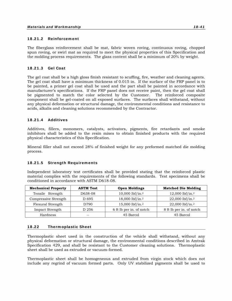
Materials and Workmanship 18-41
18.21.2 Reinforcement
The fiberglass reinforcement shall be mat, fabric woven roving, continuous roving, chopped spun roving, or swirl mat as required to meet the physical properties of this Specification and the molding process requirements. The glass content shall be a minimum of 20% by weight.
18.21.3 Gel Coat
The gel coat shall be a high gloss finish resistant to scuffing, fire, weather and cleaning agents. The gel coat shall have a minimum thickness of 0.015 in. If the surface of the FRP panel is to be painted, a primer gel coat shall be used and the part shall be painted in accordance with manufacturer’s specifications. If the FRP panel does not receive paint, then the gel coat shall be pigmented to match the color selected by the Customer. The reinforced composite component shall be gel-coated on all exposed surfaces. The surfaces shall withstand, without any physical deformation or structural damage, the environmental conditions and resistance to acids, alkalis and cleaning solutions recommended by the Contractor.
18.21.4 Additives
Additives, fillers, monomers, catalysts, activators, pigments, fire retardants and smoke inhibitors shall be added to the resin mixes to obtain finished products with the required physical characteristics of this Specification.
Mineral filler shall not exceed 28% of finished weight for any preformed matched die molding process.
18.21.5 Strength Requirements
Independent laboratory test certificates shall be provided stating that the reinforced plastic material complies with the requirements of the following standards. Test specimens shall be conditioned in accordance with ASTM D618-08.
Mechanical Property ASTM Test Open Moldings Matched Die Molding Tensile Strength D638-08 10,000 lbf/in.2 12,000 lbf/in.2
Compressive Strength D 695 18,000 lbf/in.2 22,000 lbf/in.2 Flexural Strength D790 15,000 lbf/in.2 22,000 lbf/in.2 Impact Strength D 256 6 ft lb per in. of notch 8 ft lb per in. of notch
Hardness -- 45 Barcol 45 Barcol
18.22 Thermoplastic Sheet
Thermoplastic sheet used in the construction of the vehicle shall withstand, without any physical deformation or structural damage, the environmental conditions described in Amtrak Specification 429, and shall be resistant to the Customer cleaning solutions. Thermoplastic sheet shall be used as extruded or vacuum-formed.
Thermoplastic sheet shall be homogeneous and extruded from virgin stock which does not include any regrind of vacuum formed parts. Only UV stabilized pigments shall be used to
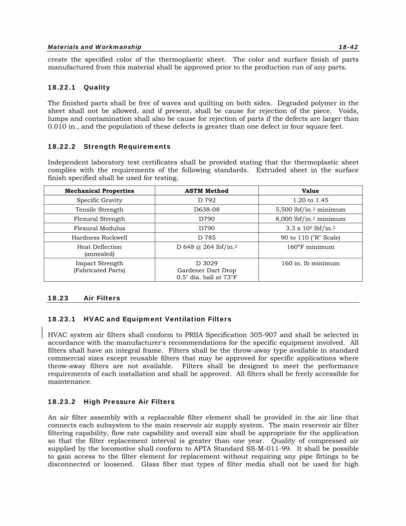
Materials and Workmanship 18-42
create the specified color of the thermoplastic sheet. The color and surface finish of parts manufactured from this material shall be approved prior to the production run of any parts.
18.22.1 Quality
The finished parts shall be free of waves and quilting on both sides. Degraded polymer in the sheet shall not be allowed, and if present, shall be cause for rejection of the piece. Voids, lumps and contamination shall also be cause for rejection of parts if the defects are larger than 0.010 in., and the population of these defects is greater than one defect in four square feet.
18.22.2 Strength Requirements
Independent laboratory test certificates shall be provided stating that the thermoplastic sheet complies with the requirements of the following standards. Extruded sheet in the surface finish specified shall be used for testing.
Mechanical Properties ASTM Method Value Specific Gravity D 792 1.20 to 1.45 Tensile Strength D638-08 5,500 lbf/in.2 minimum Flexural Strength D790 8,000 lbf/in.2 minimum Flexural Modulus D790 3.3 x 10⁵ lbf/in.2
Hardness Rockwell D 785 90 to 110 ("R" Scale) Heat Deflection
(annealed) D 648 @ 264 lbf/in.2 160ºF minimum
Impact Strength (Fabricated Parts)
D 3029 Gardener Dart Drop 0.5" dia. ball at 73°F
160 in. lb minimum
18.23 Air Filters
18.23.1 HVAC and Equipment Ventilation Filters
HVAC system air filters shall conform to PRIIA Specification 305-907 and shall be selected in accordance with the manufacturer's recommendations for the specific equipment involved. All filters shall have an integral frame. Filters shall be the throw-away type available in standard commercial sizes except reusable filters that may be approved for specific applications where throw-away filters are not available. Filters shall be designed to meet the performance requirements of each installation and shall be approved. All filters shall be freely accessible for maintenance.
18.23.2 High Pressure Air Filters
An air filter assembly with a replaceable filter element shall be provided in the air line that connects each subsystem to the main reservoir air supply system. The main reservoir air filter filtering capability, flow rate capability and overall size shall be appropriate for the application so that the filter replacement interval is greater than one year. Quality of compressed air supplied by the locomotive shall conform to APTA Standard SS-M-011-99. It shall be possible to gain access to the filter element for replacement without requiring any pipe fittings to be disconnected or loosened. Glass fiber mat types of filter media shall not be used for high
Materials and Workmanship 18-43
pressure or high volume applications. Filters shall be provided for each of the following systems and any others operated from the air supply system:
• Each air brake control assembly
• Waste system
• Door operators (if pneumatic)
• Horn
• Low pressure air filters
Replaceable media type filters shall use resin-bound, spun-glass fiber materials having an uncompressed thickness not less than 3.5 in. It shall be non-absorptive of fluids and gases, shall be processed in such a manner that material density increases progressively from air inlet to air exit side, and shall be coated with not less than 24 grams per square foot of a dust-retaining, viscous adhesive film. This film shall be stable at temperatures up to 150ºF. The filter medium shall be cut not less than 0.5 in. oversize to ensure adequate sealing between the edge of pad and its integral frame.
18.24 Wire and Cable
All wire and cable used shall exhibit the physical and electrical properties for 110ºC rated wire and cable specified in Amtrak Specification 323. High temperature wire, used for heater circuits, shall be as defined as Amtrak Specification 323.
A minimum number of wire types and sizes shall be used in the vehicle. Selection of wire size and insulation shall be based on the current carrying capacity, voltage drop, mechanical strength and temperature and flexibility requirements and in accordance with APTA Recommended Practice RP-E-009-98 and applicable AAR, ICEA, ASTM or MIL Specifications. The Contractor shall submit to the Customer for review and approval, a procedure for installation of wiring and cable, including the criteria and procedures for the repair of damaged wire or cable. This procedure shall be included in the heavy maintenance manual.
In no case shall wire smaller than the following sizes be used:
• Wire on electronic units, cards, and card racks - No. 22
• Wire on connector - No. 16
• All other wire - No. 14 unless approved by the Customer
18.24.1 Wiring - General
All vehicle wiring shall be in conformance with APTA Recommended Practice RP-E-002-98 and RP-E-009-98, Chapter 3 of the National Fire Protection Association's Publication NFPA No. 70, and the AAR Manual of Standards, Section F S-538, Wiring Practice and Rolling Stock Standard, except where otherwise specified, and except that all wire shall be as required in this Specification. Design wire amperage capacity shall comply with NEC Table 310-18, 110C Column. When more than three conductors are applied in a raceway or cable, the amperage capacity shall be derated, as described in Note 8 of Table 310-16. Circuit protection shall be in conformance with Chapter 2 of NFPA publication No. 70, Article 240.
Materials and Workmanship 18-44
18.24.2 Data Communications Wiring
All data communications (Ethernet) wiring shall be able to support EIA/TIA 568 Cat 5e communications for data on rolling stock. It shall be suitable for use in undercar and inter-car applications when installed in flexible (polyimide) or rigid conduit; it shall be suitable for the application and shall maintain long-term electrical integrity for all aspects of the EIA/TIA requirements including impedance, cross-talk, attenuation, and shielding effectiveness. The cable will also meet environmental and safety requirements associated with rolling-stock cables. The cable shall be designed with rolling-stock requirements in mind, and will support high-speed data transfer for no less than 20 years in the rail environment. All accelerated life tests performed in the qualification are specified with the intention of this service life. The cable shall be designed so that installation with normal care into new car shells or undercars will not damage its electrical integrity. The cable shall be designed so that installation in raceways with other cables is proper (cable will not be impacted by crushing or cable-to-cable abrasion). The cable shall be able to be terminated with vendor specified connectors that are suitable for use in industrial communication equipment (RJ45, M12 or similar.). The cable shall have the following characteristics:
18.24.2.1 Construction
• Conductors: Stranded silver-plated copper #22AWG (or .5mm2)
• Insulation: Radiation cross-linked data grade polyolefin 300V
• Component configuration: Wires are twisted or helically cabled to insure electrical performance to Cat 5e standards (see table) – 100Z characteristic impedance on finished cable
• Shielding: Foil and TC braid designed to meet 200MZ/m transfer impedance
• Binders/tapes: As required to enhance integrity
• Jacket: Radiation cross-linked polyolefin (low-smoke, halogen free) 0.8 mm minimum at thinnest point.
18.24.2.2 Electrical Requirements
• Impedance: 100Z+/-5Z
• Shielding effectiveness (30 Mhz- 100 Mhz): 40dB
• Voltage rating: 300V
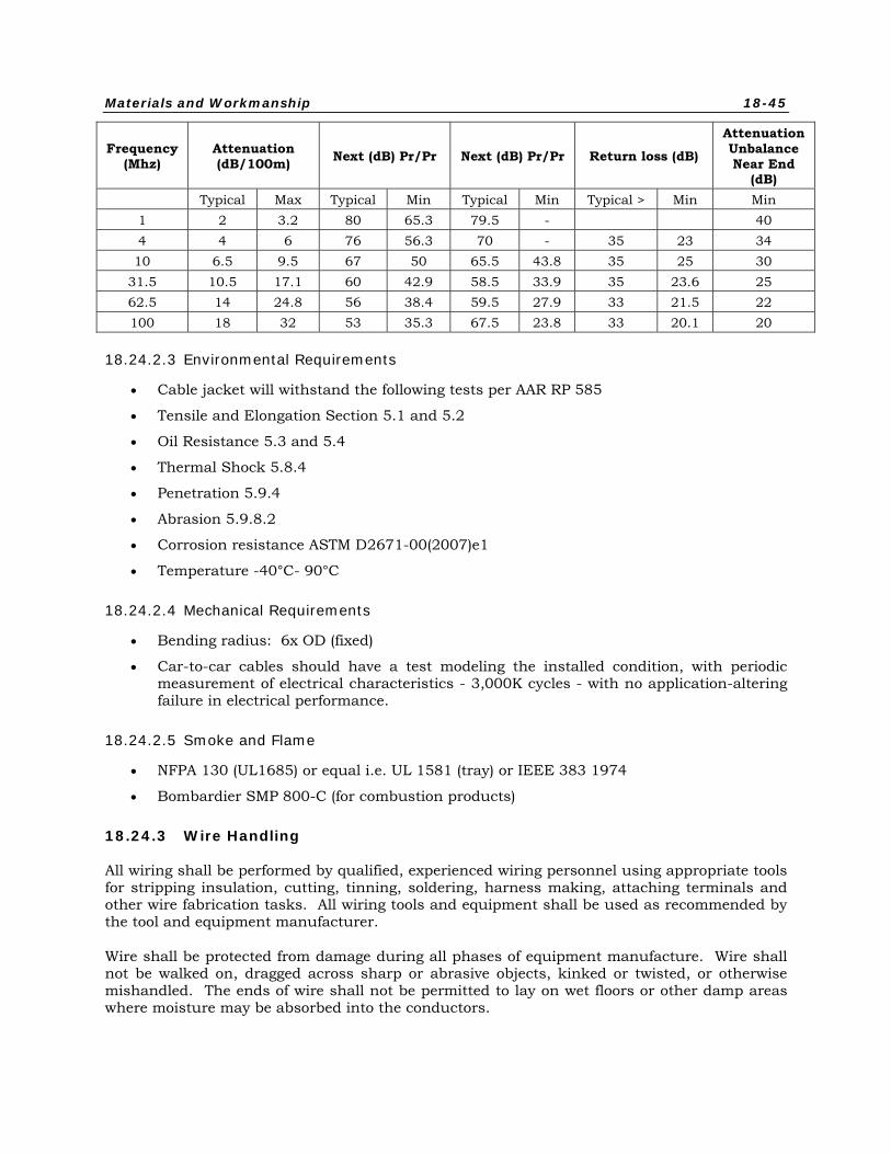
Materials and Workmanship 18-45
Frequency (Mhz)
Attenuation (dB/100m) Next (dB) Pr/Pr Next (dB) Pr/Pr Return loss (dB)
Attenuation Unbalance Near End
(dB) Typical Max Typical Min Typical Min Typical > Min Min 1 2 3.2 80 65.3 79.5 - 40 4 4 6 76 56.3 70 - 35 23 34 10 6.5 9.5 67 50 65.5 43.8 35 25 30
31.5 10.5 17.1 60 42.9 58.5 33.9 35 23.6 25 62.5 14 24.8 56 38.4 59.5 27.9 33 21.5 22 100 18 32 53 35.3 67.5 23.8 33 20.1 20
18.24.2.3 Environmental Requirements
• Cable jacket will withstand the following tests per AAR RP 585
• Tensile and Elongation Section 5.1 and 5.2
• Oil Resistance 5.3 and 5.4
• Thermal Shock 5.8.4
• Penetration 5.9.4
• Abrasion 5.9.8.2
• Corrosion resistance ASTM D2671-00(2007)e1
• Temperature -40°C- 90°C
18.24.2.4 Mechanical Requirements
• Bending radius: 6x OD (fixed)
• Car-to-car cables should have a test modeling the installed condition, with periodic measurement of electrical characteristics - 3,000K cycles - with no application-altering failure in electrical performance.
18.24.2.5 Smoke and Flame
• NFPA 130 (UL1685) or equal i.e. UL 1581 (tray) or IEEE 383 1974
• Bombardier SMP 800-C (for combustion products)
18.24.3 Wire Handling
All wiring shall be performed by qualified, experienced wiring personnel using appropriate tools for stripping insulation, cutting, tinning, soldering, harness making, attaching terminals and other wire fabrication tasks. All wiring tools and equipment shall be used as recommended by the tool and equipment manufacturer.
Wire shall be protected from damage during all phases of equipment manufacture. Wire shall not be walked on, dragged across sharp or abrasive objects, kinked or twisted, or otherwise mishandled. The ends of wire shall not be permitted to lay on wet floors or other damp areas where moisture may be absorbed into the conductors.
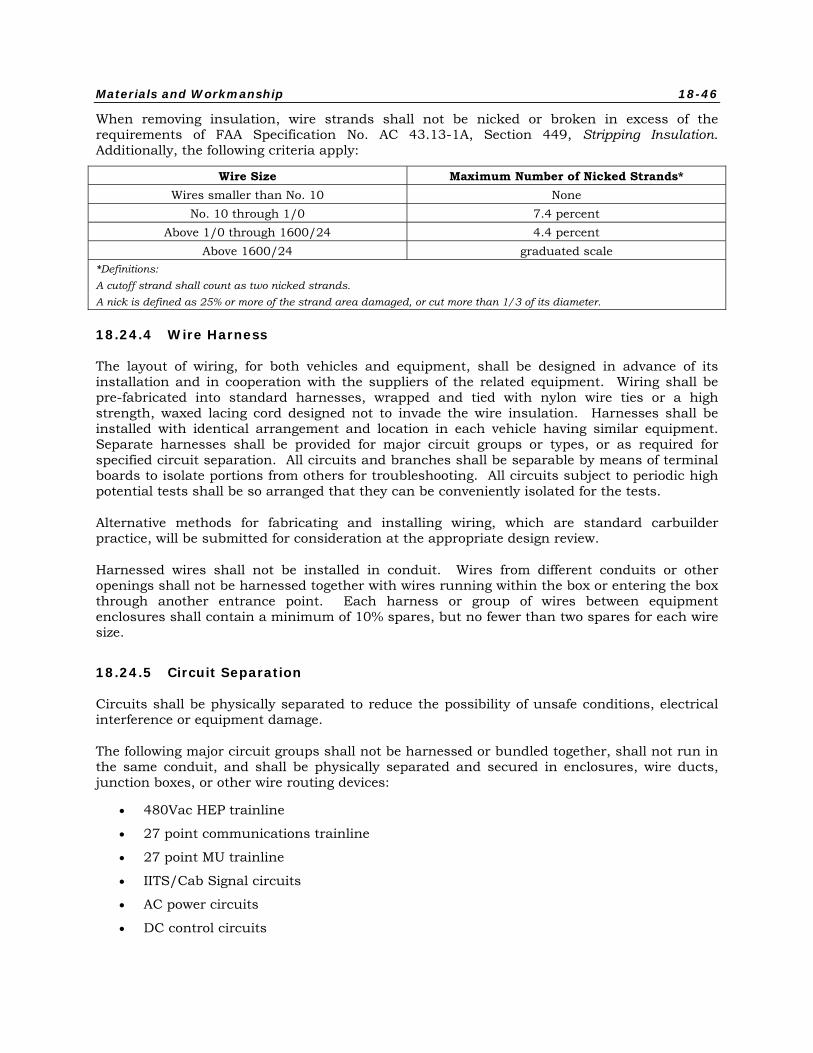
Materials and Workmanship 18-46
When removing insulation, wire strands shall not be nicked or broken in excess of the requirements of FAA Specification No. AC 43.13-1A, Section 449, Stripping Insulation. Additionally, the following criteria apply:
Wire Size Maximum Number of Nicked Strands* Wires smaller than No. 10 None
No. 10 through 1/0 7.4 percent Above 1/0 through 1600/24 4.4 percent
Above 1600/24 graduated scale *Definitions: A cutoff strand shall count as two nicked strands. A nick is defined as 25% or more of the strand area damaged, or cut more than 1/3 of its diameter.
18.24.4 Wire Harness
The layout of wiring, for both vehicles and equipment, shall be designed in advance of its installation and in cooperation with the suppliers of the related equipment. Wiring shall be pre-fabricated into standard harnesses, wrapped and tied with nylon wire ties or a high strength, waxed lacing cord designed not to invade the wire insulation. Harnesses shall be installed with identical arrangement and location in each vehicle having similar equipment. Separate harnesses shall be provided for major circuit groups or types, or as required for specified circuit separation. All circuits and branches shall be separable by means of terminal boards to isolate portions from others for troubleshooting. All circuits subject to periodic high potential tests shall be so arranged that they can be conveniently isolated for the tests.
Alternative methods for fabricating and installing wiring, which are standard carbuilder practice, will be submitted for consideration at the appropriate design review.
Harnessed wires shall not be installed in conduit. Wires from different conduits or other openings shall not be harnessed together with wires running within the box or entering the box through another entrance point. Each harness or group of wires between equipment enclosures shall contain a minimum of 10% spares, but no fewer than two spares for each wire size.
18.24.5 Circuit Separation
Circuits shall be physically separated to reduce the possibility of unsafe conditions, electrical interference or equipment damage.
The following major circuit groups shall not be harnessed or bundled together, shall not run in the same conduit, and shall be physically separated and secured in enclosures, wire ducts, junction boxes, or other wire routing devices:
• 480Vac HEP trainline
• 27 point communications trainline
• 27 point MU trainline
• IITS/Cab Signal circuits
• AC power circuits
• DC control circuits
Materials and Workmanship 18-47
• Communication circuits
• Unprotected wiring (eg, battery or HEP trainline to circuit breaker)
• Data communications (Ethernet) wiring even though it might be in the same car to car 27 point communications trainline jumper
Exceptions shall be approved by the Customer in case complete separation is not reasonably practicable.
Conductors which shall operate at potentials differing by 50 volts or more shall not be cabled together and shall not be placed in the same conduit, raceway, duct, junction box, or enclosure, except that 120VAC and 480VAC may be run in same conduits providing all the wire insulation is rated at 600VAC minimum. Where it is impossible to avoid having wires at different voltages in the same equipment enclosure, the wires shall be physically separated, bundled, and secured separately such that contact between wiring is not possible. All wiring within an enclosure shall be insulated for the highest voltage in the enclosure, unless Customer approved otherwise.
Wiring connected to transient-generating apparatus shall not be run adjacent to wiring carrying signals to, from, or between semiconductor circuits, logic circuits, vital no-motion circuits, data transmission or communication circuits. In cases in which adequate physical separation is impossible, shielded wire shall be used for all conductors involved.
18.24.6 Wire and Cable Runs
Wire and cable runs shall be properly placed to be protected from the environment, debris and be arranged to allow for proper heat dissipation per manufacturer’s requirements.
All wire and cable shall be free of kinks, insulation damage, insulation abrasions and nicked strands. Wire installation shall not be subject to accumulations of water, oil, or other foreign matter.
Cables shall be laid in place with sufficient slack at the bends so that cables will clear the inside bend surface of the strain relief device.
Conduit shall be attached to the carbody employing clamps; welding shall not be used under any circumstances.
Concealed wires, such as within conduits and wire ducts shall be such that wires may be replaced or added to without the removal of other than an access panel at each end of the wire. It shall not be necessary to disconnect or disassemble conduit to accomplish this task. Wires in conduits and wire ducts shall not utilize more than 40% of the interior cross-sectional area.
Wiring run in loom shall not be carried over a potential chafing hazard.
Wires entering any removable box shall be harnessed and secured to facilitate removal of the box.
All wires and cables shall be fully protected against any contact with any surface other than that designed specifically to support or protect them. This applies to all current carrying wires, cables or buses on the vehicle.
Materials and Workmanship 18-48
18.24.7 Undercar
The 480Vac trainline conductors shall be cleated in place; No. 6 AWG and larger may be cleated in place or run in rigid conduit.
All undercar wiring smaller than No. 6 AWG shall be run in Rigid Galvanized Steel (RGS) conduits in an approved manner. Conduits shall be of waterproof construction. Permanently retained watertight strain relief bushings, with insulated throat liners of an approved design, shall be used at locations where wires, cords or harnesses enter or exit conduit, junction boxes and equipment enclosures. In addition, strain relief bushings on equipment enclosures shall include a permanently retained O-ring type seal.
Wires or cables shall not pass through or over the battery compartment and shall not pass over heat generating equipment, even if the wires or cables are in conduit.
Rigid galvanized steel conduit shall be run to all rigid-mounted enclosures. RGS conduit shall be run as near as possible to resiliently mounted equipment, with flexible conduit, not to exceed 18” in length, completing the run.
Flexible conduit shall not be used for any application on the exterior or underside of the car without Customer approval.
Open undercar wiring shall be protected over the trucks by running the wiring through RGS conduit, with suitable protective bushings applied at the ends.
Conduit routing and the connection to boxes shall minimize exposure to water entering the conduit: for example, conduit should not enter from the top of the enclosure if at all possible. Drip loops shall be employed as appropriate.
18.24.8 Exterior of Roof
All wiring to roof-mounted equipment shall be run in electrical metallic tubing steel or rigid galvanized steel conduits within the carshell.
Wires or cables exposed or in conduit shall not pass over or near heat generating equipment.
Conduit routing and the connection to boxes shall minimize exposure to water entering the conduit: for example, conduit should not enter from the top of the enclosure if at all possible. Drip loops shall be employed as appropriate. Boxes shall be raised above surfaces where water, snow/ ice could accumulate (including from plugged drains), to reduce the likelihood hood of water incursion.
18.24.9 Under Floor
Wiring run under the floor shall be either in conduit or wire duct. Care shall be taken to ensure water does not enter the conduit/ wire duct from above, such as from car cleaning.
Materials and Workmanship 18-49
18.24.10 Interior
Any wiring passing through the floor shall be run in rigid conduit. Wiring, even if enclosed in loom, must not be run through partitions without suitable bushings being provided at such points of passage. Conduit openings from below must extend at least 1 in. above the floor level to ensure water cannot enter the conduit from above, such as from a wet floor.
All 480V wiring above the car floor and within the sides, ends or roof of the car shall be carried in EMT or rigid steel conduits. Short runs, not to exceed 18 in., of flexible conduit may be employed to make final connections to equipment.
All wiring in the walls shall be in EMT or rigid conduit. Wiring in the roof shall be carried in thin-wall aluminum or steel conduit, in metal duct or “Panduit” material meeting the requirements of PRIIA Specification 305-903. All flexible non metal conduits shall be installed in protected areas only, unless specifically approved by the Customer. In wire ducts, wire shall be secured within and including each entrance and exit point, to prevent chafing movement.
18.24.11 Cable Cleating and Support
Open-run cable shall be supported by using split-block cleats of molded neoprene rubber, spaced no more than 4 feet apart. Slack shall be allowed in the cable to accommodate both thermal expansion and contraction of cable.
Each cleat shall have a channel-shaped stiffener of at least 10 gage material on the side away from the mounting bracket which shall act to spread the bolt clamping force over the entire length of the cleat. Bolts shall have lock nuts.
Cleats shall be designed to grip each cable individually and firmly, but without causing any damage to cable insulation, including cold flow of the insulation. Cleats shall include spacers in the mounting holes to prevent crushing the cleat by overtighting the mounting bolts. Each cable in the cleat shall have its own cutout sized to the correct wire diameter. The cleat material shall be fire retardant insulating material with a durometer of 50 to 60.
Cleated cables shall be routed and supported such that they cannot, under any combination of forces and car movement, touch each other or any other part of the car, except the cleat cushioning material.
18.24.12 Wire Securement and Termination
All wiring shall be secured and protected against movement, chafing, and any contact with conductive, sharp, or abrasive objects including the inside surfaces of wire runs.
No wiring shall be secured directly to the vehicle structure, equipment enclosures, or any metallic surface. Wiring securing devices shall be either completely non-metallic or metallic with a resilient, insulating member between the wiring and the metallic portion of the device.
All wiring shall be located and secured such that normal equipment motions, maintenance access, heat sources and the environment do not damage or reduce the life of the wiring.
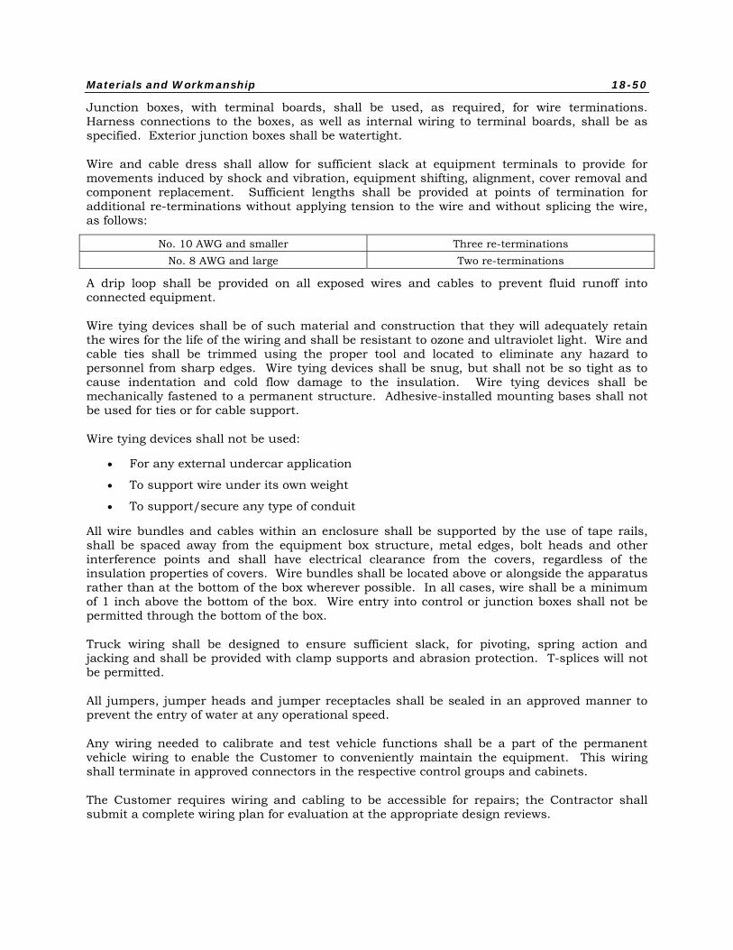
Materials and Workmanship 18-50
Junction boxes, with terminal boards, shall be used, as required, for wire terminations. Harness connections to the boxes, as well as internal wiring to terminal boards, shall be as specified. Exterior junction boxes shall be watertight.
Wire and cable dress shall allow for sufficient slack at equipment terminals to provide for movements induced by shock and vibration, equipment shifting, alignment, cover removal and component replacement. Sufficient lengths shall be provided at points of termination for additional re-terminations without applying tension to the wire and without splicing the wire, as follows:
No. 10 AWG and smaller Three re-terminations No. 8 AWG and large Two re-terminations
A drip loop shall be provided on all exposed wires and cables to prevent fluid runoff into connected equipment.
Wire tying devices shall be of such material and construction that they will adequately retain the wires for the life of the wiring and shall be resistant to ozone and ultraviolet light. Wire and cable ties shall be trimmed using the proper tool and located to eliminate any hazard to personnel from sharp edges. Wire tying devices shall be snug, but shall not be so tight as to cause indentation and cold flow damage to the insulation. Wire tying devices shall be mechanically fastened to a permanent structure. Adhesive-installed mounting bases shall not be used for ties or for cable support.
Wire tying devices shall not be used:
• For any external undercar application
• To support wire under its own weight
• To support/secure any type of conduit
All wire bundles and cables within an enclosure shall be supported by the use of tape rails, shall be spaced away from the equipment box structure, metal edges, bolt heads and other interference points and shall have electrical clearance from the covers, regardless of the insulation properties of covers. Wire bundles shall be located above or alongside the apparatus rather than at the bottom of the box wherever possible. In all cases, wire shall be a minimum of 1 inch above the bottom of the box. Wire entry into control or junction boxes shall not be permitted through the bottom of the box.
Truck wiring shall be designed to ensure sufficient slack, for pivoting, spring action and jacking and shall be provided with clamp supports and abrasion protection. T-splices will not be permitted.
All jumpers, jumper heads and jumper receptacles shall be sealed in an approved manner to prevent the entry of water at any operational speed.
Any wiring needed to calibrate and test vehicle functions shall be a part of the permanent vehicle wiring to enable the Customer to conveniently maintain the equipment. This wiring shall terminate in approved connectors in the respective control groups and cabinets.
The Customer requires wiring and cabling to be accessible for repairs; the Contractor shall submit a complete wiring plan for evaluation at the appropriate design reviews.
Materials and Workmanship 18-51
18.24.13 Marking
All terminals boards and terminal posts shall be plainly marked with non-conductive hot stamping type markings so that they shall be easily identified. Devices shall be labeled via silk-screening onto panels, mechanically-attached plastic labels (adhesives are not acceptable alternate), or other permanent means approved by the Customer in design review.
Wires shall be marked with sleeve-type labels with permanent typed-on lettering, such as Raychem TMS or approved equal, or with non-conductive hot stamping type markings. Both ends of each wire are to be identified. A wire 4 in. or less in length shall need only one label. For No. 16 and smaller wires, including multi-conductor cables, where individual wire marking would be impractical, color coding of each wire will be satisfactory.
18.24.14 Cable and Wire Identification
The Contractor shall provide a listing of all wire codes and device and connector identification used on its equipment as part of the integrated schematics manual.
The identification system shall be designed to utilize the minimum number of alphanumeric characters to identify devices and interconnecting wiring. Device, terminal and wire identification is intended to provide unique, consistent, clear, concise and recognizable identification of wiring and devices as an aid to maintenance of electrical systems. The wire-designation system shall be one which relates the designation in some way to indicate where it shall go and where it shall come from. Each individual piece of wire shall be given its own distinct identification so that it shall be positively identified at its opposite end without the necessity for "ringing through." As much as possible, naming shall be consistent among all the Customer equipment. This naming system will be employed on the following:
• Electrical Arrangement Drawings
• Electrical Schematics
• Wiring Diagrams
• Labels on hardware
• Car Electrical Panels, etc.
• Device names: circuit breakers, indicators lights, switches, relays, contactors, pressure switches, etc.
• Car Wiring
• The above categories on drawings provided by different vendors (for example, air brake schematic and electrical schematics)
By using the nomenclature and appropriate schematic, an electrician shall be able to easily identify any point in a circuit, such as an auxiliary contact, and locate that point on the hard-ware.
The identical name shall be used for a given component in all references - arrangement and schematic drawings, wiring diagrams, panel and switch plate legends, and maintenance manuals.
Materials and Workmanship 18-52
It shall be the Contractor's responsibility to ensure that:
• All equipment suppliers conform to this Specification;
• A consistent numbering system is used throughout the vehicles; and
• Component device and wire names are not duplicated.
At a minimum, the following major electrical system components shall be identified:
• Electrical panels
• Contactors and motor starters
• Relays and timers
• Switches and circuit breakers
• Electronic components
• Terminal blocks
• Connectors
• Each wire
• All labels shall be permanent and expected to be legible for the life of the vehicle.
• Labels shall be easy to read and observable without having to disturb wiring, especially for:
• Relay names
• Contactor/Motor starter names
• Terminal block and terminal identity.
• In cases where two or more identical panels are used, the respective panel names "A" and "B" (as appropriate) shall be affixed to the car body or mounting plate, not the panel.
• Numbering system shall be consistent between Contractor and component supplier, such as floor heat wire names. It shall be possible for an electrician to connect all external car wiring to a panel without requiring a drawing.
18.24.15 Pulling Compound
Pulling compound shall be non-conductive, non-hygroscopic, non-odorous, and shall not attract vermin.
18.24.16 Solder
Solder shall be in accordance with ASTM Standard B32-08, Grade 60B. A flux of non-corrosive type shall be applied immediately before soldering and removed after soldering.
18.24.17 Tape
Electrical tape shall be polyvinyl chloride in accordance with UL 510, Standard Insulating Tape, CSA Standard C22.2, No. 197-M1983, PVC Insulating Tape, or equivalent approved railway
Materials and Workmanship 18-53
practice. Electrical tape shall meet or exceed the voltage rating of wire where the tape is applied.
18.25 Wire and Cable Connections
All wire and cable shall be free of kinks, insulation damage, insulation abrasions and nicked strands. Wire installation shall not be subject to accumulations of water, oil, or other foreign matter.
Cables shall be laid in place with sufficient slack at the bends so that cables will clear the inside bend surface of the strain relief device.
Conduit shall be attached to the carbody employing clamps; welding shall not be used under any circumstances.
Concealed wires, such as within conduits and wire ducts shall be such that wires may be replaced or added to without the removal of other than an access panel at each end of the wire. It shall not be necessary to disconnect or disassemble conduit to accomplish this task.
Wiring run in loom shall not be carried over a potential chafing hazard.
Wires entering any removable box shall be harnessed and secured to facilitate removal of the box.
All wires and cables shall be fully protected against any contact with any surface other than that designed specifically to support or protect them. This applies to all current carrying wires, cables or buses on the vehicle.
All equipment enclosures and junction boxes shall be fitted with terminal boards or connectors. The Contractor shall submit the proposed design and product line for all connections for approval. Number 6 and smaller type terminal boards and quick-disconnect terminals, other than those stated herein, will only be permitted with approval.
18.25.1 Terminal Boards and Terminal Points
All electrical terminal points and terminal boards of wire size AWG 10 or larger shall have brass studs and connections, each of which shall be locked using a single brass nut with brass flat washer and a plated spring-type lock washer. Studs, nuts, and washers may also be made of corrosion-resistant plated steel, where approved. Each board or connector shall have the necessary number of terminations plus a minimum of 10% spares, but not fewer than one spare unless approved. Binding head screw type terminal boards will be permitted only where approved. All terminal boards shall be in accordance with Military Specification MIL-T-55164C.
All wires of size range AWG 12 to 14 shall use modular spring lock terminal blocks. The terminal block modules will be mounted on din rails. The supplier shall provide standard 35mm wide DIN-rail in 7.5mm, 15mm and 58mm heights. The DIN-rail shall meet RoHS (Restriction of Hazardous Substances Directive) standards and shall be available perforated or unperforated. Materials will include chromated-steel, copper, and aluminum. The modules shall be color coded for the ability to tell the signal type at a glance. The terminal blocks shall be available in the following colors/color combinations of gray, blue, red, yellow/green, black,
Materials and Workmanship 18-54
yellow, orange and brown. The metal body shall contain a high strength spring steel spring element that will provide a gas-tight connection with the conductor.
Spring connection shall be stainless steel. The terminal blocks shall come with car body ground modules that are connected directly to carbody ground. The terminal blocks shall come with insertable shorting plugs. The terminal blocks will have snap in positive lock labels. Terminal Blocks shall have a method of labeling for easy identification which is universal across all connection technologies. The modules will have a place to label the terminal number as well as the terminal block name. Each wire shall have a ferrule on its end and be able to be inserted by engaging the spring with a standard 3mm slot size screw driver.
Terminal Block accessories and bridging systems shall be compatible and interchangeable with all connection technologies (screw, spring and IDC technology) including flexible bridging system, modular testing, standardized labeling system and pluggability features.
Threaded studs shall have a minimum of 2-1/2 threads exposed beyond the final nuts. Adequate space shall be provided to permit connecting wire terminals with standard tools. All terminals shall be properly torqued to assure sound connections. Spacers shall not be used.
Jumpers between terminal board points shall be brass or plated steel. Wire jumpers between adjacent terminals of terminal boards will not be permitted.
Terminal blocks located outside the carbody or operating at 480V or above will employ closed bottom blocks.
An approved permanent marking strip on each terminal board shall be provided and attached adjacent to the wire junction point to identify the wires attached thereto. CDRL
A maximum of two terminals shall be connected to any one binding screw. A maximum of four terminals shall be connected to any one threaded stud, provided that there is no interference between terminal barrels. On terminal boards, the wiring shall be arranged so that no more than two terminals are connected to a stud, from each side of the terminal boards.
18.25.2 Wire Terminations
Terminals and connections used throughout the vehicle shall be the mechanical, solderless, crimp type made by AMP Incorporated or other approved manufacturer with a comprehensive line of terminals, connector pins and application tools available. The Contractor shall submit the proposed product line for approval. Terminals shall be tested to Military Specification MIL-T-16366F for temperature rise, voltage drop, vibration, current overload and corrosion.
All wire terminations shall be accessible to remove or replace. Wire terminations shall not be covered by other wires.
Terminals and connections shall be attached to the wiring with proper crimping tools and dies as recommended by the manufacturer. Application tooling shall incorporate die or piston stops to prevent over crimping. To prevent under crimping, all application tooling shall incorporate a “full cycle” feature that once started, requires the tool to be brought to the stops before the crimped connection can be removed. The Contractor and his suppliers shall employ a certification process to ensure that all tooling remains within calibration to properly crimp the lugs.
Materials and Workmanship 18-55
Spade and hook-type terminals shall not be used. Corrosive protection shall be provided for all base materials.
Conductors subject to motion relative to the terminal shall be protected by suitable means to prevent breakage of the conductor at or near the terminal. Sufficient slack shall be provided in all wires and cables to prevent breaking or pulling out of bushings and terminals. A maximum of one wire shall be crimped in any one terminal.
18.25.3 Power Cable Terminations
Power cables shall be terminated with an approved compression terminal. Sufficient cable slack shall be provided to preclude breaking or pull-out from bushings or terminals and to allow two terminal changes. Cable conductors shall be clean prior to installation of terminals. Compression terminals shall be applied using tools and procedures recommended by the terminal manufacturer for that purpose. Swaging tools shall be of a type that ensures complete swaging in every case.
18.25.4 Cable Connectors
All cable connectors shall conform to MIL-C-5015, or an equivalent standard as approved by the Customer. They shall employ removable crimp contacts of the correct size for the wire being terminated. Except as noted below, the connector contact area shall be plated with a minimum of 0.000030 in. of gold over a minimum of 0.000050 in. of low stress nickel. For high current applications, the connector contact area shall be plated with a minimum of 0.00010 in. of silver. Adjacent connectors shall either use different inserts or different insert orientations to prevent erroneous connections. One piece of all cable connectors shall be rigidly mounted.
Connectors shall be keyed so as to not be accidentally interchanged between adjacent connectors. Spare contact allocation shall be 10% to 15%, but no less than 4, per connector. Power and control wiring shall be separated in different connectors if they exceed 120VAC. Disconnected plugs will be supported so as to not drop to the ground, floor or other position in which they might be readily damaged. Connectors are to be mounted to provide convenient hand access so as to be easily mated and unmated.
All cable connectors used in exterior locations shall be of the environmental watertight variety and a molded type wherever possible (such as speed sensors). Cable connectors shall be equipped with sealing gaskets on the front mating surface and on the back where the cable enters. Bolts within the connector shall be long enough to ensure that there is sufficient room to terminate the cable wires within the connector body. The cable jacket shall be held by a clamp within the connector body. Unused connector pin positions shall be sealed with either connector contacts or plastic sealing plugs designed for that purpose.
Plastic bodied connectors shall not be used.
Except as provided above, all cable connectors in exterior locations, shall be 1/4-turn, bayonet-lock, quick disconnect type connectors, or approved equal. They shall conform to all provisions in MIL-C-5015, or an approved standard, except for the screw coupling requirement.
In waterproof interior locations, the use of non-weatherproof connectors will be allowed as approved. All other connector requirements specified in this section which do not directly apply to weatherproofing shall be met.
Materials and Workmanship 18-56
18.25.5 Quick-Disconnect Terminals
Only Customer-approved quick-disconnect terminals may be used. They shall be modular and they shall provide positive terminal engagement and be shock and vibration proof. All terminals shall be provided with insulation equal to that of the wire. No "push-to-fit" (FAST-ON) type terminals will be permitted unless specifically approved by the Customer for that unique application.
18.25.6 Grounding/ Bonding Connections
Grounding and bonding shall be done in accordance with APTA Standard SS-E-005-98. All grounding and bonding jumpers and straps shall be sized to handle fault current for which the voltage drop shall not exceed 25V. The bonding method employed shall not produce a dc resistance in excess of 0.0025 ohms, or more than 0.025 ohms at 150 kilohertz for any applied ac voltage. Grounding and bonding jumpers, and brazed shunt straps shall be flexible.
The car body shall be grounded to each truck frame by means of a separate cable which shall be sized to safely ground the car under normal conditions.
The 120VAC, 60 Hz, single-phase service shall be separately and firmly grounded to the car body structure and have a green indicating color band applied to the terminations.
All apparatus operating at 480VAC and not directly grounded to the car body through its mounting shall have grounding straps. This particularly applies to resiliently mounted equipment.
18.25.7 Wire Splicing
Splicing of conductors shall be avoided and shall be permitted only with approval on a case-by-case basis. Splicing of conductors in conduit will not be permitted. In the event a splice is approved, it shall be in a junction box and the spliced joint shall be mechanically as strong and have the same conductivity as any other part of the conductor. The splice shall be an insulated permanent crimp splice in accordance with Military Specification MIL-T-7928G, Type II, Class I, and shall be installed with the crimping tool and die of the splice manufacturer. All splices shall be insulated with a self-sealing, weathertight, seamless shrink tubing. The outside diameter of the spliced portion of the cable after the insulation is applied shall not exceed the outside diameter of the unspliced portion by more than 40%. Splices shall be identified in the integrated schematic.
18.26 Conduit
18.26.1 Types
Thin-wall EMT type conduit shall conform to Federal Specification WW-C-563A. Flexible metal conduit shall conform to Federal Specification WW-C-566C or MIL-T-81914.
Materials and Workmanship 18-57
18.26.2 Size and Fill
Conduit shall be sized such that the sum of the cross-sectional areas of the conductors and their insulation does not exceed 40% of the cross-sectional area of the conduit for three or more conductors. For two conductors, a limit of 31% shall be used, while for a single conductor, a limit of 53% will be permitted. Where conduit having a length not exceeding 24 in. without bends of more than 15º is used between enclosures, a maximum fill of 60% will be permitted.
18.26.3 Installation
A run of conduit between junction boxes and/or pulling outlets shall not contain more than the equivalent of four quarter bends, 360° total, including the outlet fittings. Bend radii at the inner surface of the bend shall be no less than eight times the nominal inside diameter of the conduit.
All conduit bends and offsets used shall be made by the use of special forms or tools and shall have the largest radius possible so that wires can be pulled without the use of tackle or power.
Conduit shall be securely clamped with all runs electrically grounded to make a continuous ground. Suitable approved insulation to prevent electrolysis shall be provided where steel and aluminum are in contact.
All conduit shall be arranged to prevent moisture traps and shall drain toward control boxes, except that all open-ended conduits shall be installed in such a manner as to ensure gravity drainage out the end. The conduit arrangement and installation shall be subject to approval.CDRL
18.26.4 Conduit Fittings and Junction Boxes
The conduit fittings and junction boxes for vehicle wiring shall be as manufactured by the Contractor or by a supplier of a comprehensive line of parts. The Contractor shall submit the proposed product line for approval. All conduit fittings and junction boxes shall be provided with gasketed covers. CDRL
18.26.4.1 Boxes
All exterior junction boxes shall be fabricated of steel with a minimum wall thickness of 14 gauge. All exterior junction boxes shall be weatherproof and shall be connected in such a way that drainage from equipment groups will not pass through conduit into the junction boxes. Interiors of all junction boxes shall be primed and then protected with a white, insulating epoxy powder coating. Equipment areas containing non-insulated electrical devices at more than 120 volts to ground shall be plainly marked with warning signs worded DANGER – XXX VOLTS. Covers for electrical junction boxes shall be accessible at all times without having to remove other equipment.
Materials and Workmanship 18-58
18.26.4.2 Conduit Interface
The open ends of conduit shall be provided with strain relief type fittings with extended rubber bushings, bell-mouth fittings, or insulated throat box connections as approved. All conduit entries into removable equipment boxes shall be secured by means of a bolt-on watertight access panel.
18.26.4.3 Covers
All junction box covers shall be retained by captive screws. All fasteners used in junction boxes shall be stainless steel. All covers shall be designed to accept or mate with a bulb-type clamp-on seal.
18.26.4.4 Wireways
Wireways will be permitted in approved ceiling locations only. They will not be permitted in the car body sidewall area. Only conduit will be permitted in the car body.
All wireways shall be “Panduit”, meeting PRIIA Specification 305-903, or of rigid steel with a coating to minimize the risk of oxidation and rust formation. The trays shall be adequately supported throughout their entire length in an approved manner. There shall be absolutely no sharp edges. The trays shall be completely de-burred before installation on the vehicles. Grommet clamps shall be provided at all locations where cables or wires enter or leave the wireways. Under no circumstances shall leads be draped over the edge of the wireways, with or without wireway edge protection.
Wireways shall be located to provide access to the harnesses contained within for maintenance action.
Bends in wireways shall be avoided; however, if they are required, approved protection shall be provided to avoid insulation chafing at the bends.
Wireways shall not contain more than 30 current-carrying conductors at any cross-section. The sum of the cross-sectional areas of all conductors contained at any cross-section of a wireway shall not exceed 40% of the interior cross-sectional area of the wireway.
All wire and cable shall be securely fastened within wireways to eliminate movement and resultant chafing.
18.27 Electrical and Electronic Designs
18.27.1 Reliability Standards
All electrical and electronic control systems shall be designed and components shall be selected using the Reliability Design HandBook No. RDH376 as a guide. All devices shall be derated to operate within the "Acceptable" region for electrical stress versus temperature for "Airborne Applications". If there is a conflict between guidelines given elsewhere in this Specification and the Reliability Design HandBook, the more restrictive condition shall govern. Other service-proven devices may be submitted for approval.
Materials and Workmanship 18-59
18.27.2 Ability to Repair
All electrical devices including such items as PC boards, relays, contactors, and filters shall be capable of being repaired by the Customer in its electronics laboratory. It is recognized that some equipment, due to its complexity, cannot be economically repaired by the Customer. In preliminary design reviews, the Builder shall identify all situations where this could be the case, for ruling by the Customer, whose decision shall be final.
Units shall not be sealed, potted or constructed to prohibit repair by the Customer. Units that must be potted or sealed by design other than Lowest Level Replaceable Units (LLRUs) shall have a minimum 10-year warranty.
18.27.3 Hardware
All hardware associated with electronic and electrical systems, including the case, heat sinks, mounting brackets, etc., shall be protected against moisture, oxidation and common airborne contaminants.
18.27.4 Wiring
Wire selection, routing and securement shall be accomplished with the goal of having the wire and cable last the life of the car body. All movement and chafing of wire and cable shall be eliminated. The use of additional wear material(s) to extend life without elimination of the movement, wearing or chafing will not be permitted.
18.27.5 Optical Fibers
Any application of optical fibers shall be approved prior to implementation. This approval is not intended to discourage the use of optical fibers. Rather, it is to verify reliability and maintainability of the proposed application. In no case shall the on-car repair of an optical fiber require sophisticated or complex polishing and alignment. The connections between optical fibers and car-replaceable units shall be via approved "quick disconnects".
18.28 Electrical Devices and Hardware
All electrical devices shall be service-proven. Electrical connections shall use either captive screws or captive nuts, with crimp terminals.
18.28.1 Contactors and Relays
Contactors shall be defined as those devices, which control one kilowatt or more of electricity through their main contact tips. Unless specified, all contactors shall meet or exceed the requirements of PRIIA Specification 305-906, section 4.3- 4.5.
Relays shall be defined as those devices which switch less than one kilowatt of electricity through their contacts. Unless specified, all relays shall meet or exceed the requirements of PRIIA Specification 305-906, section 4.3- 4.5.
All contactor and relay coils shall be suppressed with a solid state device to prevent transients being generated onto the low-voltage network.
Materials and Workmanship 18-60
All devices shall be satisfactorily tested for proper functioning in orientations up to 30° from the mounting plane as fitted in the vehicle. They shall be installed to be fully accessible for inspection, servicing, repair and ease of replacement. There shall be no more than two wires connected to any one terminal. Installation shall be such that, when required, arc spray is directed, by a non-asbestos arc chute, away from ground and adjacent electrical devices.
All devices shall be constructed and utilized in a fail-safe manner; that is, all failures shall be in a direction such that neither: the passengers, the crew, nor the equipment is placed at risk.
All magnetic devices shall be a heavy-duty type suitable for railroad service. They shall be constructed such that the main tips or contacts "make" and "break" with a wiping or rolling motion that minimizes build-up of deposits and/or pitting. Contact and/or tip replacement shall not exceed 5% of the total number during any annual inspection period.
Device contacts or tips shall not be placed in parallel to increase the total current load in excess of the rating for an individual contact or tip.
All devices shall be readily identifiable by means of a permanent, durable marking strip giving the device circuit designation. No identifications shall be obscured, or partially obscured, by wire routing. The identification strip shall be mounted adjacent to the mounting of said device.
Bifurcated contacts shall be used in low voltage applications whenever necessary due to dry contacts or low current switching requirements.
All time delay relays shall be of the R-C delay or solid state type. No mechanical or pneumatic time delay devices will be permitted.
Where plug-in relays are approved, the relay shall be positively retained by means of a retaining clip or bar. This device shall be captive, of rugged construction and shall be easily positioned for relay installation and removal without the need for special tools. When the relay is removed, the retainer shall itself be retained so that it cannot come in contact with devices, which may have exposed energized electrical circuits, and it shall not interfere with the operation of any other device when in this position.
18.28.2 Switches
Switches are defined as those manually operated devices that control less than one kilowatt of electrical power through their contacts. Unless otherwise specified, switches shall meet the requirements of MIL-S-3950. Toggle and push button switches shall be per MIL-S-3950, MIL-S-8805, MIL-S-83731 or equal, as approved by the Customer. All switches provided shall be of high quality and shall be fully suitable for the rigors of the Customer's service environment, including cycle life. The design and selection of all switches shall be subject to review and approval.
Switches shall be provided with a "keying" feature such that after installation, the body of the switch will be constrained from mechanical rotation.
Under no circumstances shall poles of switches be placed in parallel in order to carry currents in excess of the contact pole rating given by the manufacturer.
There shall be a maximum of two wires connected to each terminal of the device.
Materials and Workmanship 18-61
Switches shall be individually replaceable without disconnecting or removing anything other than the mounting fasteners and electrical connections of the switch to be replaced.
All control switches, which are subject to water splash, which is defined to mean any switches mounted near windows or doors, or mounted on the Engineer’s control console, shall be environmentally sealed.
18.28.3 Circuit Breakers
All circuit breakers provided shall be extremely rugged and fully suitable for the service intended. They shall meet the requirements of Amtrak Specification 498, section 4.4. Design and selection of all circuit breakers not available within the Customer’s material control system shall be subject to review and approval.
The continuous current rating of thermal-magnetic trip circuit breakers shall be selected in accordance with ANSI C37.16 for the load and type of service specified. All thermal-magnetic trip circuit breakers shall conform to the requirements of ANSI C37.13 and ANSI C37.14.
All circuit breakers of the same rating shall be of the same manufacture and model throughout the vehicle. Circuit breaker current rating shall be clearly and permanently marked and shall be completely visible after installation.
The ON, OFF and TRIPPED positions of all circuit breakers shall be permanently marked on the handle or the case of the circuit breaker. The circuit breaker, when tripped, shall assume a distinct position between the ON and OFF positions to permit determination of the fact that it has been tripped by either its overcurrent or shunt trip elements.
Circuit breakers shall be individually replaceable without disconnecting or removing anything other than the mounting fasteners and electrical connections of the breaker to be replaced.
Each and every input power circuit shall be protected by an individual circuit breaker. Separate circuit breakers shall be provided for major assemblies or functions. No circuit breaker shall protect more than one circuit, nor shall any one circuit be protected by more than one circuit breaker. Circuit breaker terminals shall not be used as junction points.
All circuit breakers shall be sized by current rating and tripping time to protect both the associated equipment and the minimum size wire used for power distribution within the protected circuit without causing nuisance tripping.
Each circuit breaker pole shall be equipped with adequate means of arc extinction to prevent flashover.
Circuit breakers shall not be intended for use as on/off switches. All circuits requiring on/off switches shall be so equipped.
Materials and Workmanship 18-62
18.28.4 Fuses
Circuit protection functions that can be performed by fuses shall normally be performed by appropriately rated circuit breakers. Fuses shall be used only where specifically called for in the Specification or where the use of circuit breakers is not technically feasible, and only with specific approval. Fuses may be considered in applications as follows:
• To protect solid-state equipment from catastrophic damage.
• Where current or voltage levels prohibit circuit breakers.
Fuses shall be permanently identified adjacent to the fuse, including functional name, fuse type and rating. The rating of each fuse shall be permanently and clearly marked directly on each fuse.
Fuses shall be readily accessible. All fuses mounted in exterior equipment boxes shall be accessible without going under the vehicle.
Fuse holders shall contain fuse retention devices at both ends.
Unless explicitly noted otherwise in this Specification, all fuse compartments shall have a spare fuse of identical size and rating for each "in-circuit" fuse, and shall be mounted next to the respective "in-circuit" fuse with the fuse holder clearly marked SPARE FUSE. The spare fuse holder shall not be enclosed and shall not consist of any loose parts.
The use of current limit-type fuses is prohibited.
18.28.5 Bus Bars
Bus bars are to be fabricated from OFE (Oxygen Free Electronic) or ETP (Electrolytic Tough Pitch) copper (CDA 101). The bus bar conductivity shall be 100% IACS. All bus bar joints shall be silver or tin plated.
Current densities, other than at joints, shall not exceed 1000 amperes per square inch, and in any case shall not exceed a value which would cause a bus bar temperature rise greater than 30°C. Current densities in joints shall not exceed 150 amperes per square inch.
Bus bars shall be properly brazed together at joints unless bolted connections are found to be absolutely necessary for maintenance purposes and are approved. The overlap at bus bar joints shall be no less than 10 times the thickness of the bus material. Bus bar connection bolts shall be torqued to obtain a uniform bus bar connection pressure of 200psi. Bolting hardware shall be plated steel with Belleville washers to maintain connection pressure.
Except for connection areas, bus bars shall be safety insulated, using a high-dielectric, powder coating or other approved means. Tape will not be acceptable. Bus bars that are behind insulating panels will be exempt from this requirement.
18.28.6 Capacitors and Resistors
Dry tantalum capacitors, shall be used in place of aluminum electrolytics, except for high values which are not commercially practical or available, in which case long life grade aluminum electrolytics shall be used. Dry tantalum capacitors shall be in hermetically sealed
Materials and Workmanship 18-63
metal cases, except for surface mounted types when hermetically sealed metal cases are not avaliable.
Commutating capacitors shall be a paper or plastic film type, shall incorporate a non-toxic impregnant, and shall be chosen to give a service life of at least 20 years. Filter capacitors shall have high ripple current rating for long life.
Capacitors shall be derated 20% for voltage based on the nominal supply voltage and maximum case temperature. If filter capacitors are exposed to low ripple voltages, lesser values of derating may be accepted if it can be shown that reduced operating temperatures can be achieved due to lower dissipation; however, the sum of the dc and ac ripple voltages shall always be less than the capacitor's voltage rating at a maximum case temperature of 85°C.
All resistors shall be operated at less than 50% of their rated maximum power dissipation. Other power resistor applications may be submitted for approval of lower derating, on a case-by-case basis.
Use of trim potentiometers or adjustable resistors shall not be permitted without Customer approval. Generally, the need for adjustments shall be avoided by use of the appropriate circuitry, and stable precision components.
18.28.7 Transformers and Inductors
Transformers and inductors shall be rated at 20% over the maximum specified current level.
18.28.8 Switch, Circuit Breaker and Fuse Panels
All switch, circuit breaker and fuse panels shall conform to Amtrak Specification 498, with dead front, mounted in the specified equipment enclosures and switch/ electric lockers.
Each switch and circuit breaker panel shall carry the necessary apparatus, arranged to be easily accessible to connections and designed to prevent operating or maintenance personnel from coming in contact with live parts when operating the switches or circuit breakers. All live portions of the protected circuitry shall be completely concealed so that no danger of electrocu-tion or shock exists from the touching of the panel or any appurtenances or devices mounted thereto.
All switches, breakers, fuses, and indicating lights shall be provided with a nameplate of raised or recessed lettering on the dead front, clearly identifying the circuit which each controls and its circuit designation. The dead front panel shall conform to NFPA No. 70, Article 384. A wiring gutter shall be provided along the top, sides and bottom, for the routing of high voltage leads to their designated circuit breakers.
The panel shall be secured by approved, captive fasteners and shall be configured for easy removal so that maintenance and repair action is not impeded.
Power distribution to circuit breakers and switches shall be from a bus bar or bus circuit. Distributing power by successive or "daisy-chained" connections between device terminals will not be permitted.
Materials and Workmanship 18-64
18.28.9 Battery Backup Circuits
Any device provided that requires a backup battery must be designed with a five year battery life unless specifically approved by the Customer.
18.29 Semiconductor Standards
Semiconductors shall be selected to withstand all continuous and transient voltage and power demands present in the circuit application without damage or reduction in life. All circuit designs shall provide for the presence of high current switching equipment on the vehicle and the resultant induced voltages and currents in electrical equipment.
All transistors and diodes shall be silicon devices that meet or exceed the specifications of all of the original equipment devices; and shall secure proper operation over the full dynamic range for which each circuit shall be designed. Alternatively semiconductor numbers traceable to the manufacturer and component characteristics shall be included in the maintenance and spare parts manuals.
18.29.1 Rating
Discrete semi-conductors shall have the following minimum voltage breakdown rating, dependent on the use:
• Transistors and thyristors operated from the nominal battery supply, or those connected to trainlines, shall have minimum breakdown ratings of four times the maximum circuit rating. Suppression devices shall be provided as necessary to protect the devices and limit the circuit voltage.
• Diodes operated from the nominal battery supply, used as suppression devices, or those connected to trainlines shall have a minimum Peak Inverse-Voltage rating (PIV) of 1000V.
• All discrete semiconductors operated in inverters or other isolating devices shall have minimum breakdown ratings of two times the maximum circuit voltage (except where specifically detailed otherwise). Suppression shall be provided, as necessary, to protect the devices and maintain the circuit voltage and current operating conditions within all limits specified by the semiconductor manufacturer.
• All diodes, transistors and thyristors shall have a PIV rating of at least twice the maximum normal operating voltage but in no case less than 800V. This requirement shall not apply to circuits operating from an isolated power supply and whose wires and circuits shall be kept physically separate from battery-supplied wires and circuits by at least one-half inch.
Semiconductors shall be placed in a clean and ventilated environment which shall favor easy replacement.
All semiconductor junction temperatures shall be limited to 150ºC (or to the maximum rated temperature for the device, whichever is less) or less at maximum ambient temperature and at maximum rated output power.
All semiconductors shall be operated at less than 50% of the maximum continuous current rating or maximum continuous power rating, whichever is more restrictive.
Materials and Workmanship 18-65
Integrated circuits operated from the battery supply through inverters or other isolating devices shall be operated within the voltage and current ratings specified by the manufacturer, derated to less than 50% of the maximum stress level at the maximum operating temperature of the device as specified by the manufacturer.
Where the supplies to integrated circuits are regulated and surge protected, the voltage rating shall be 15% below the manufacturer's recommended maximum. In addition, the maximum power shall be limited to 50% of the manufacturer's specified maximum at the maximum operating temperature.
Integrated circuits shall be soldered into the printed circuit board; plug-in connectors are not permitted.
All gallium arsenide and similar optical semi-conductors shall be rated for operation over the temperature range of –40°C to +85ºC.
All semiconductors shall be rated “industrial or automotive grade” for reliable operation over the temperature range of -40ºC to +85ºC, except for discrete power semiconductors (>=1 Watt) which shall be rated for temperature range of -55ºC to +125ºC. Exceptions shall not be taken without proper identification and written authorization from the Customer prior to first article tests.
All suppliers of semiconductors shall be selected according to a recognized standard such as ISO-9002 Section 4.6 or better. Exceptions shall not be taken to the above provisions without proper identification and written authorization from the Customer prior to the first article inspection.
18.29.2 Availability and JEDEC Registration
All thyristors, transistors and diodes shall be JEDEC registered and numbered, and must be available from at least two different manufacturers. Non-JEDEC registered devices carrying more than 10 amps may be used provided that the Contractor obtains prior approval based on submission of each item's completed procurement specifications and evidence of availability from two or more manufacturers based on those specifications.
All semiconductors shall be available from at least two manufacturers and available from U.S. distributors. Single source devices, such as high voltage power devices, microprocessors, ASICs and related support chips may be used only if approved. Such devices shall be essential to the proposed equipment, shall meet the service-proven requirements and shall be supplied by veteran manufacturers likely to support the device.
18.29.3 Burn-in
Either all integrated circuits shall be burned-in and screened for defects to MIL-STD-883G, Method 5004, Reliability Class B or all units shall be 24 hours burned in according to an approved process and re-inspected for defects. The records must be maintained for review by the Customer inspectors.
Materials and Workmanship 18-66
18.30 Printed Circuit Board Standards
Printed circuit boards shall be designed, constructed and inspected to MIL-STD-275, unless more stringent requirements are noted here. Traces shall be made as wide as practical, with the minimum width being based on a 10ºC temperature rise. Run spacing shall conform to MIL-STD-275.
Circuit board material shall be per MIL-P-13949, with a minimum thickness of 0.0625 in. using type GB or GH base material. Type GE material may be used for boards which have no components whose power dissipation is greater than two watts and when said board is not mounted adjacent to components dissipating greater than two watts. The copper laminate shall be firmly attached to the board and shall be resistant to blistering and peeling when heated with a soldering iron.
Components with pins shall be mounted only on one side. Connections shall be made to the other side or internal layers via plated through holes. Surface mounted components may be mounted on both sides if part of an approved existing design.
All circuit boards shall be inherently stiff or shall be reinforced to prevent damage due to vibration or handling. Unless otherwise approved circuit boards larger than 100 in.2 shall be centrally stiffened.
All equipment shall be designed using stable, high tolerance components to eliminate the need for adjustments. Compensation for manufacturing tolerances may be made through parallel precision resistors. All replacement printed circuit boards shall be directly interchangeable without any additional adjustments.
All printed circuit boards shall be of the "plug-in" type, with positive support against vibration, except where approved otherwise.
Not more than one PC board shall be stacked on each PC card.
Printed circuit board connectors shall be heavy duty, high reliability, and proven in prior successful rail service. All printed circuit boards shall plug into keyed sockets. Contact fingers and edge connectors shall have 0.000050 in. thick gold plating.
18.30.1 Marking
All circuit boards shall be labeled with a part number, serial number and descriptive nomenclature.
All components shall be labeled on the board with component drawing references and such other information as may be required to repair and troubleshoot the board. The component and wiring sides of the board shall each be marked to indicate capacitor and diode polarity, and at least two leads or one lead and a graphic symbol indicating orientation of all transistors and thyristors.
Integrated circuits and other multi-terminal devices shall have an index mark on the component side of the board, visible with the component inserted, to indicate proper keying and insertion; the first pin on all integrated circuits packages shall be identified on the wiring side of the board.
Materials and Workmanship 18-67
For boards whose component density is greater than 2.25 components per square inch, the Contractor may submit an alternate marking plan for possible approval. Such a plan should include board marking, augmented by layout drawings.
18.30.2 Component Mounting
Components shall be fastened to the board in such a manner as to withstand repeated exposure to shock and vibration. Large components shall be supported in addition to the solder connections. Power resistors shall be mounted on standoffs so that the resistor bodies do not contact the board, spaced far enough away from the board so that resistor-produced heat will not discolor or damage the board or adjacent wires or components.
18.30.3 IC and Device Sockets
IC and device sockets shall comply with MIL-S-83502 and MIL-S-83734, as is applicable for the device.
18.30.4 Conformal Coating
Both sides of the assembled printed circuit boards shall be coated with a clear insulating and protective coating material conforming to MIL-I-46058C, or approved equal.
The coating shall be easily removed with a brush-applied solvent or penetrated by a hot soldering iron when a component must be unsoldered. The coating solvent shall not adversely affect board-mounted components.
All IC sockets, connectors and test points shall be masked when the coating is applied.
18.30.5 Keying
All printed-circuit boards shall be "keyed" to prevent insertion into the wrong socket. Further, circuit boards in safety related control systems, such as friction brakes, cab signal, and systems which can cause damage or unsafe train operation if the vehicle is operated with a card removed, shall be connected through a safety circuit or checked through an auto test to disable the vehicle if a circuit board is removed.
18.30.6 Circuit Board Connectors
Printed circuit board connectors shall be heavy duty, high reliability, two-part type with a history of successful service in rail applications and shall be approved by the Customer prior to commencing design.
Connectors which comply with MIL-C-55302, and which have plated contacts as described below, are considered to comply with the requirements of this section.
The connector contact area shall be plated with a minimum of 0.000050 in. of gold over a minimum of 0.000050 in. of low stress nickel.
Card edge connectors are prohibited.
Materials and Workmanship 18-68
All connectors within one panel assembly shall be keyed to prevent damage or malfunction due to incorrect insertion.
18.30.7 Testing
Sufficient clearance shall be provided between components to allow testing, removal and replacement without difficulty due to lack of space.
Test points shall be provided in appropriate locations on modules and printed circuit boards. A negative return test point shall also be provided. The test points shall either accept and hold a standard 0.080 in. diameter tip plug or shall be a turret lug similar to Cambion No. 160-1026-01-05, or approved equal, with sufficient clearance to permit it to accept a standard oscilloscope probe clip, and shall be identified by appropriate markings.
When test points are not suitable, as for complex circuits or micro-processor based control system, self-diagnostic routines and/or special test equipment may be used to identify the failed Lowest Replaceable Unit.
18.30.8 Plated-Through Holes
In addition to the general guidelines of the Institute of Printed Circuits (IPC), the following requirements shall be met:
• Plating Holes - Copper plate shall be a minimum of 0.001 in. minimum average thickness, and 0.003 in. maximum average thickness. Solder plates shall be 0.0003 in. minimum average thickness and 0.0015 in. maximum average thickness.
• Plated Hole Defects - No more than three voids per hole will be acceptable. Total area of the voids shall not exceed 10% of the total wall area. The largest void dimension shall not exceed 25% of the core diameter or the board thickness, whichever is smaller. There shall be no pits, voids or cracks at the junction of the whole wall and terminal area to a depth of 1-1/2 times the total copper thickness on the surface.
• Enclosures
All circuit boards that are rack mounted shall plug into racks containing the mating half of the circuit board connector. The circuit board rack shall mount in an enclosure conforming to requirements in this document. The rack, circuit board and circuit board hardware shall be designed as an integrated system.
The rack and enclosure shall provide environmental and EMI shielding necessary to meet the requirements of this Specification.
Printed circuit boards shall be positively retained by means of keeper bars or other approved method. The enclosure or rack cover shall not be used to retain the circuit boards.
Each circuit board shall be fitted with an ejector or hand grip to assist in board removal. The rack and the edge of each board, or the card ejector, shall be labeled with corresponding numbers to identify board location within the enclosure.
Materials and Workmanship 18-69
18.30.9 Extenders
Printed circuit board extenders (six sets of each type) shall be provided by the Contractor for test purposes. At least two extenders of each type shall be available for use and evaluation throughout the design conformance and acceptance test programs.
18.31 Microprocessor-Based Systems
The microprocessor-based control systems shall be based on an established family of microprocessors in wide use in the control system industry. They shall be supported by a full range of software development languages and diagnostic programs.
Should the Contractor elect to use multiprocessor bus architecture, the architecture shall be based on the Intel Multibus, Motorola VME or similar bus used widely in industrial process control equipment. Alternative bus structures may be submitted for the Customer approval.
Program code and fixed data shall be stored in Programmable Read-Only Memory (PROM) or Erasable Programmable Read Only Memory (EPROM). Either static or dynamic Random Access Memory (RAM) or EPROM may be used for temporary data storage. All EPROM windows shall be covered with labels that are opaque at the Ultraviolet (UV) erasing wavelengths.
Battery-backed RAM may be used only to store fault information. Batteries shall be sized to retain data for at least six months without charging and shall be located such that leakage cannot damage any control system components. Battery life shall be no less than five years, regardless of type.
At least 30% additional memory space shall be installed and available for future modifications to program code, fixed data space and temporary data space.
18.31.1 Software
Software may be written in a high or low level language. The language, and its implementation for the selected microprocessor system, shall be commercially available in English.
All software, whether interrupt based or polled, shall always assign the highest priority to safety-related tasks.
Software shall perform the following basic functions:
• Implement the desired control scheme such that the specified performance is achieved;
• Monitor all inputs for unsafe, erroneous, or unknown conditions or combinations of conditions;
• Sample all input conditions at rates sufficient to detect and remedy all unsafe or damaging conditions in the shortest possible time. Sampling rates and program execution times shall be such that the control system is not the limiting factor in response to unsafe or damaging conditions;
• Limit all output commands to safe levels regardless of any combination of input conditions;
Materials and Workmanship 18-70
• Perform self-diagnostic routines and respond promptly, safely, and predictably to detected faults;
• Respond safely and predictably when powering up or recovering from power interruptions. All power interruptions likely to have corrupted temporary storage shall be detected and cause the system to re-initialize all affected routines and temporary data. Detection of power interruptions may be by hardware.
• Permit thorough interrogation of all input, output and internal conditions by external diagnostic equipment.
18.31.2 Isolation and Interfacing
Any microprocessor-based control system shall be powered by dedicated isolated power supplies driven from the vehicle battery circuit.
All control system input and output signals shall be through isolation buffers unless specifically approved by the Customer. High voltage inputs and outputs shall be isolated external to the microcomputer card rack unless specifically approved by the Customer. Low voltage (battery and logic voltage level) inputs and outputs shall be isolated via buffer cards in or external to the microcomputer card rack.
The isolation buffers shall:
• Protect and isolate the control system from damage due to overvoltage, undervoltage, transients, shorts and open circuits.
• Perform necessary voltage transformations.
• Remove noise and undesired signals.
• Limit, pre-process, discriminate and format those signals that would otherwise require excessive processor time.
• Consist of optical isolators, transformer isolators, and other circuits appropriate to the application.
18.31.3 Software Documentation
The Contractor shall submit, for approval, a software quality assurance plan in accordance with ANSI/IEEE Standard 730-2002. For reference, this Standard has the following minimum software documentation requirements:
• Software requirements specification
• Software design description
• Software verification and validation plan
• Software verification and validation report
• User documentation
Materials and Workmanship 18-71
The Software Design Description (SDD) shall be in accordance with ANSI/IEEE Standard 1016-1998. The final Software Design Description shall include details are summarized below only for information:
Level 1 Computer description and operation Level 2 Software architecture, basic program and functions Level 3 Detailed flow information Level 4 Annotated compiler/assembly listing Level 5 Detailed memory map and listing Level 6 Input/output port map
At its option, the Customer will participate in both the Software Requirements and the Preliminary Design Review, as defined by ANSI/IEEE Standard 730-2002. Following these reviews, the Contractor shall submit, for approval, the Software Requirements Specification and the Software Design Description. All subsequent changes to these documents shall also be submitted and approved prior to implementation.
The Contractor shall provide at the final design review a hardware and software safety plan in accordance with 49CFR Section 238.105.
18.32 Auxiliary AC Motors
Motors shall limit starting current to within industry recommended practices and be equipped with NEMA C-frame type sealed bearings that shall not require re-lubrication for the life of the bearing. Bearings shall be sized to provide a minimum life of 6 years. Any motor mounted with the shaft vertical shall have bearings suitable for this type of application. Any motor which is exposed to weather shall be a type specifically designed for the environment. Any motor with a vertical shaft and subject to the weather shall include a moisture seal on the shaft to prevent water from entering the bearings.
18.33 Recyclable Materials
Expendable items that are recyclable shall be identified with the appropriate symbols, as defined by the Society of the Plastics Industry, permanently imbedded in the material.
* End of Chapter 18 *