Embed Size (px)
Citation preview
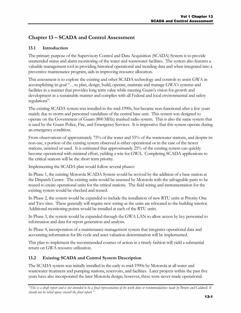
Vol 1 Chapter 13 SCADA and Control Assessment
“This is a draft report and is not intended to be a final representation of the work done or recommendations made by Brown and Caldwell. It should not be relied upon; consult the final report.”
13-1
Chapter 13 – SCADA and Control Assessment
13.1 Introduction
The primary purpose of the Supervisory Control and Data Acquisition (SCADA) System is to provide unattended status and alarm monitoring of the water and wastewater facilities. The system also features a valuable management tool in providing historical operational and trending data and when integrated into a preventive maintenance program, aids in improving resource allocation.
This assessment is to explore the existing and other SCADA technology and controls to assist GWA in accomplishing its goal “…to plan, design, build, operate, maintain and manage GWA’s systems and facilities in a manner that provides long term value while meeting Guam’s vision for growth and development in a sustainable manner and complies with all Federal and local environmental and safety regulations”.
The existing SCADA system was installed in the mid-1990s, but became non-functional after a few years mainly due to storm and personnel vandalism of the central base unit. This system was designed to operate on the Government of Guam (800 MHz) trunked radio system. This is also the same system that is used by the Guam Police, Fire, and Emergency Services. It is imperative that this system operate during an emergency condition.
From observations of approximately 75% of the water and 55% of the wastewater stations, and despite its non-use, a portion of the existing system observed is either operational or in the case of the newer stations, unwired or used. It is estimated that approximately 25% of the existing system can quickly become operational with minimal effort, yielding a win for GWA. Completing SCADA applications to the critical stations will be the short term priority.
Implementing the SCADA plan would follow several phases:
In Phase 1, the existing Motorola SCADA System would be revived by the addition of a base station at the Dispatch Center. The existing units would be assessed by Motorola with the salvageable parts to be reused to create operational units for the critical stations. The field wiring and instrumentation for the existing system would be checked and reused.
In Phase 2, the system would be expanded to include the installation of new RTU units at Priority One and Two sites. These generally will require new wiring as the units are relocated to the building interior. Additional monitoring points would be installed at each of the RTU units.
In Phase 3, the system would be expanded through the GWA LAN to allow access by key personnel to information and data for report generation and analysis.
In Phase 4, incorporation of a maintenance management system that integrates operational data and accounting information for life cycle and asset valuation determination will be implemented.
This plan to implement the recommended courses of action in a timely fashion will yield a substantial return on GWA resource utilization.
13.2 Existing SCADA and Control System Description
The SCADA system was initially installed in the early to mid-1990s by Motorola at all water and wastewater treatment and pumping stations, reservoirs, and facilities. Later projects within the past five years have also incorporated the later Motorola design; however, these were never made operational.
Vol 1 - Chapter 13 SCADA and Control Assessment
“This is a draft report and is not intended to be a final representation of the work done or recommendations made by Brown and Caldwell. It should not be relied upon; consult the final report.” 13-2
The original system was the Motorola Intrac Remote Terminal Unit (RTU) series consisting of a Power Supply, Basic Module, Status Input Module (SI-8), Analog Input Module (AI-8), Control Output Module (CO-8) and a Maxtrac radio unit. Several units also were equipment with Line Isolation Modules to isolate the higher input voltages from the RTU. These units were equipped with a set of rechargeable batteries for operation during a power outage. The Intrac series is no longer manufactured by Motorola, although parts are available by after market supplies.
The later installed RTU systems are of the Motorola MOSCAD-L series design. These units have removable circuit boards and comprise a central processor, Status Input Modules, analog input module, output module, a handheld transceiver radio, and battery back-up.
The older Maxtrac model radio output power is estimated to be 30 watts while the new models were estimated at 2.5 watts. This is in comparison to cellular phone transmitters whose power output is in the less than 0.5 watt range.
The radio frequencies used are within the Government of Guam (Gov Guam) trunked system (800 MHz Band) through four repeater sites providing coverage throughout the island. This is the same system that is used by the Guam Police, Fire, and Emergency Services. The Guam Police (GPD) manages the user database and assigns the talk group and identification of each unit on the system.
The repeater sites are secured and backed by uninterruptible power supplies (UPS), stand-by generator, and radio redundancies. Several sites are shared with GTA (Guam Telephone). The repeaters are linked by GTA’s fiber communications link. Future plans are to back this link with Gov Guam owned microwave communications as well as to add repeater sites to provide better coverage.
The SCADA system relies on input information from process instrumentation in the field. These include basic items such as power fail, water pressure high, pump operate, generator operate, flow pulsing, wet well level and alarms, etc. The output of the SCADA at the water pumping stations is designed to provide pump starting and stopping capability in response to a tank or reservoir high level condition. Locations without commercial power were equipped with photovoltaic panels to charge the batteries.
13.3 Methodology
The methodology used to conduct this assessment consisted of site surveys and observations of the existing SCADA and control equipment, review of digital photographs, field voltage checks and communication testing (where possible). The survey covered the one year period of June 2004 to May of 2005.
The results were tabulated using the rating scale as follows on the next page:
Vol 1 Chapter 13 SCADA and Control Assessment
“This is a draft report and is not intended to be a final representation of the work done or recommendations made by Brown and Caldwell. It should not be relied upon; consult the final report.”
13-3
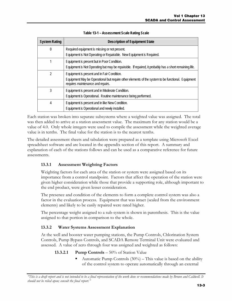
Table 13-1 – Assessment Scale Rating Scale
System Rating Description of Equipment State
0 Required equipment is missing or not present. Equipment is Not Operating or Repairable. New Equipment is Required.
1 Equipment is present but in Poor Condition. Equipment is Not Operating but may be repairable. If repaired, it probably has a short remaining life.
2 Equipment is present and in Fair Condition. Equipment May be Operational but require other elements of the system to be functional. Equipment requires maintenance and repairs.
3 Equipment is present and in Moderate Condition. Equipment is Operational. Routine maintenance being performed.
4 Equipment is present and in like New Condition. Equipment is Operational and newly installed.
Each station was broken into separate subsystems where a weighted value was assigned. The total was then added to arrive at a station assessment value. The maximum for any station would be a value of 4.0. Only whole integers were used to compile the assessment while the weighted average value is in tenths. The final value for the station is to the nearest tenths.
The detailed assessment sheets and tabulation were prepared as a template using Microsoft Excel spreadsheet software and are located in the appendix section of this report. A summary and explanation of each of the stations follows and can be used as a comparative reference for future assessments.
13.3.1 Assessment Weighting Factors
Weighting factors for each area of the station or system were assigned based on its importance from a control standpoint. Factors that affect the operation of the station were given higher consideration while those that provide a supporting role, although important to the end product, were given lesser consideration.
The presence and condition of the elements to form a complete control system was also a factor in the evaluation process. Equipment that was intact (sealed from the environment elements) and likely to be easily repaired were rated higher.
The percentage weight assigned to a sub-system is shown in parenthesis. This is the value assigned to that portion in comparison to the whole.
13.3.2 Water Systems Assessment Explanation
At the well and booster water pumping stations, the Pump Controls, Chlorination System Controls, Pump Bypass Controls, and SCADA Remote Terminal Unit were evaluated and assessed. A value of zero through four was assigned and weighted as follows:
13.3.2.1 Pump Controls – 50% of Station Value Automatic Pump Controls (30%) – This value is based on the ability
of the control system to operate automatically through an external
Vol 1 - Chapter 13 SCADA and Control Assessment
“This is a draft report and is not intended to be a final representation of the work done or recommendations made by Brown and Caldwell. It should not be relied upon; consult the final report.” 13-4
system such as the SCADA system. The rating is higher if all elements of the system are intact and operational.
Manual Pump Controls (15%) – This value is based on the ability of the control system to operate in a manual mode through a local control switch. This rating is higher if the local control or mechanical by-pass means are available and can be safely operated by non-electrical personnel.
Motor Protection Controls (5%) – This value is based on the application of motor protective devices at the station such as Class 10 overload protection, phase monitor, motor protective devices, surge protection, motor thermal switches, etc. The rating is higher with the higher degree of protection without any protective device being bypassed or removed.
13.3.2.2 Chlorination System Controls – 25% of Station Value
Automatic Pump Controls (10%) – This value is based on the ability of the controls system to operate automatically. The controlling items here are the field instrumentation of flow switches and being interlocked with the main pump starter.
Manual Pump Controls (10%) – This value is based on the value of the control system to safely operate through a local control device. The rating is higher if this local device is protected and interlocked with the main pump controller.
Chlorination Control Valves (5%) – This value is based on the chlorination system ability to shut off any chlorine flow when the chlorination system is shut down. A valve or other device to prevent this will improve the rating.
13.3.2.3 Pump By-Pass Controls – 10% of Station Value Valve Controls (5%) – This value is based on the by-pass system
having the essential elements for operation from the electrical controls to the solenoid valve, limit switch, and control piping. Having all the elements improves the rating.
Automatic Valve Actuator (5%) – This value is based on the condition and presence of the valve actuator. The lack of corrosion and degree of maintenance improve this rating.
13.3.2.4 SCADA Remote Terminal Unit – 15 % of Station Value SCADA RTU (5%) – This value is based on the condition and
presence of the Motorola RTU unit. The essential elements of the power supply, control module, input and output modules, and wiring affect the rating.
SCADA Antenna and Cabling (2.5%) – This value is based on the condition and presence of the RTU antenna and communication cabling. The presence and condition of all elements improve this rating.
Vol 1 Chapter 13 SCADA and Control Assessment
“This is a draft report and is not intended to be a final representation of the work done or recommendations made by Brown and Caldwell. It should not be relied upon; consult the final report.”
13-5
Enclosure (2.5%) - This value is based on the condition and location of the RTU enclosure. Installations within the building or under the eave scored higher. Those on the building exterior or exposed to the elements were rating low because of the heavy corrosion on the protective enclosure.
Flow meter and Sensor (2.5%) – This value is based on the condition of the flow transmitter and receiver. The value is higher when the unit is operational and indicating and lower when one element is missing. Stations where the newer flow meters with signal output capability were installed were rated lower.
Pressure Transducer and Alarm (2.5%) – This value is based on the condition and presence of the pressure transducer, pressure switch, and its integration into the SCADA system. A higher rating was given to those stations where the transducer is located downstream of the wellhead as opposed to being at the wellhead. The presence of the pressure transducer with the wiring intact also improved the rating.
13.3.3 Wastewater Pumping Station Assessment Overview
The evaluation format at the wastewater pumping stations was performed in similar fashion with that of the water pumping stations. The Pump Controls, Sump Pump, and SCADA Remote Terminal Unit elements were considered and assessed as follows:
13.3.3.1 Pump Controls – 70% of Station Value Automatic Pump Controls (40%) – This value is based on the
stations’ use of an operational level control system for pump control. The condition of the wiring, motor starter, control relays, and control cabinet affected the rating. A higher value was given to those stations where a newly installed pump control cabinet was installed with all elements operational. Stations with cabinets that had modified wiring or control equipment were considered lower.
Manual Pump Controls (20%) – This value is based on the ability of the control system to operate safely through a manual selector at a local control device. This function would require operator intervention to maintain the wet well level.
Motor Protection Controls (10%) – This value is based on the application of motor protective devices at the station such as thermal overload protection, phase monitor, surge protection, motor winding thermal switches, etc. The rating is higher when a higher degree of protection is implemented, without any protective device being bypassed or removed.
13.3.3.2 Sump Pump – 10% of Station Value Control Cabinet (5%) – The operational condition and location of
the control cabinet affect this rating. Having the location of the control cabinet in the drywell decreases this rating.
Vol 1 - Chapter 13 SCADA and Control Assessment
“This is a draft report and is not intended to be a final representation of the work done or recommendations made by Brown and Caldwell. It should not be relied upon; consult the final report.” 13-6
Level Control (5%) – The presence of float or other level control device is essential for automatic operation. Stations where a sump pump was manually operated were rated lower.
13.3.3.3 SCADA Remote Terminal Unit – 20% of Station Value SCADA RTU (10%) – This rating is based on condition and
presence of the essential elements of the Motorola SCADA RTU Unit. Items such as the power supply, control and input/output modules and wiring affect this rating.
SCADA Antenna and Cabling (5%) – This value is based on the presence and condition of the SCADA antenna and cabling.
Enclosure (5%) – This value is based on the condition and location of the RTU equipment enclosure. Units installed within the building or under the building eave scored higher than those located on the windward side or completely exposed to the environment.
13.3.4 Wastewater Treatment Plants Assessment Explanation
Refer to Appendix 4 – Tables 1 through 9 for the wastewater treatment plants detailed ratings. Table 5 is a summary of the detailed assessments for the wastewater treatment plants.
13.4 SCADA and Control System Site Observations
Site visits were made to approximately 75% of the water wells and booster pump stations and 55% of the wastewater pumping stations with the following observations:
13.4.1 SCADA Observations
13.4.1.1 SCADA General Observations
During the field observations of the existing Motorola SCADA System, the following items were observed:
Several stations appeared to be operational in the sense that radio transmissions were heard through the radio speaker. When the cabinet door was opened (intrusion alarm), the radio transmitted a signal with the status input card indicating actuation of the toggle switch.
At a few stations, the radio unit was operational but the RTU status input card had no indication, even in the test mode.
At a few stations, the RTU status input card displayed an indication, but the radio was not operational.
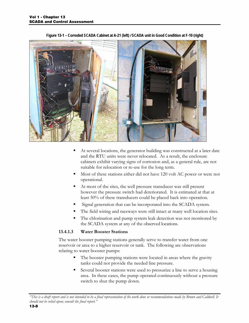
At several stations, there was no electrical power at the RTU cabinet. Those RTU cabinets that were installed in the exterior environment and
adjacent to the water well or equipment sites had visible signs of corrosion. Several of those near the ocean were badly corroded. For those not heavily corroded and sealed, the equipment on the interior appeared to be in fairly good condition.
Vol 1 Chapter 13 SCADA and Control Assessment
“This is a draft report and is not intended to be a final representation of the work done or recommendations made by Brown and Caldwell. It should not be relied upon; consult the final report.”
13-7
The RTU cabinets installed on the building exterior but under the roof eave, appeared to be in fairly good condition.
At several stations, the wiring appeared to be incomplete. There were cases of wiring installed within the cabinets but not terminated. A few conductors were identified, however, many were not. The masking tape that was used to identify wiring and equipment had deteriorated.
At the newer stations, the field and power wiring was installed but not terminated.
No evidence of the central base station units was located. These would have consisted of at least two personal computers (PC), field interface units (FIU), and software. These devices are likely to be obsolete in present times (likely a 386 or 486 type computer).
The directional (YAGI) antennas were basically intact at most stations although a few were re-directed or damaged as a result of prior typhoons.
From information gathered, the initial SCADA system was installed during a time period when either only the well head or the chlorination shed existed. The generator building was constructed at a later date.
Most of the stations had 120 volt AC power present at the RTU cabinet. In many cases, the RTU Power Supply Module had 120 volt present at the input terminals but no 24 volt DC output voltage was observed at the radio or RTU modules.
Most stations had their antennas and cabling intact. The RTU cabinets that were installed within the building or under a
covered building eave exhibited less corrosion than those installed directly exposed to the weather.
13.4.1.2 Water Pumping Stations
The following is a summary of existing SCADA system observations relating to the Motorola System in place at the water pumping stations. These were primarily located in the northern and central districts.
A minimum of nine stations (Station F-1, F-13, F-15, F-16, F-17, F-18, D-22, M-20A, and F-21) had operational radio units. These units were able to transmit or receive status information. The analog input signals (flow and pressure) were noted to be wired to the analog input module. Discrete status input points (pump run, generator run, power fail, chlorine detected, etc) were not wired at most stations although wiring was present at the RTU.
At four stations (Y-16, Y-17, Y-21A, Y-23), the newer Motorola MOSCAD-L units were installed, however, they were not powered or wired. These units are capable of being programmed to work with the newer SCADA technology.
A majority of the water well sites were originally installed without a means of sheltering the RTU from the elements. This resulted in the RTU’s being installed adjacent to the well or water line to being mounted on the chlorine storage building. In both cases, the equipment was still exposed to the environmental elements.
Vol 1 - Chapter 13 SCADA and Control Assessment
“This is a draft report and is not intended to be a final representation of the work done or recommendations made by Brown and Caldwell. It should not be relied upon; consult the final report.” 13-8
Figure 13-1 – Corroded SCADA Cabinet at A-21 (left) / SCADA unit in Good Condition at F-10 (right)
At several locations, the generator building was constructed at a later date and the RTU units were never relocated. As a result, the enclosure cabinets exhibit varying signs of corrosion and, as a general rule, are not suitable for relocation or re-use for the long term.
Most of these stations either did not have 120 volt AC power or were not operational.
At most of the sites, the well pressure transducer was still present however the pressure switch had deteriorated. It is estimated at that at least 50% of these transducers could be placed back into operation.
Signal generation that can be incorporated into the SCADA system. The field wiring and raceways were still intact at many well location sites. The chlorination and pump system leak detection was not monitored by
the SCADA system at any of the observed locations.
13.4.1.3 Water Booster Stations
The water booster pumping stations generally serve to transfer water from one reservoir or area to a higher reservoir or tank. The following are observations relating to water booster pumps:
The booster pumping stations were located in areas where the gravity tanks could not provide the needed line pressure.
Several booster stations were used to pressurize a line to serve a housing area. In these cases, the pump operated continuously without a pressure switch to shut the pump down.
Vol 1 Chapter 13 SCADA and Control Assessment
“This is a draft report and is not intended to be a final representation of the work done or recommendations made by Brown and Caldwell. It should not be relied upon; consult the final report.”
13-9
The pump motor used were either horizontal or vertical air cooled, type construction pumps.
At most stations, generator backup power was provided.
13.4.2 Control System Observations
13.4.2.1 Water Pumping Stations
Most of the deep well water pumping stations are currently operating in manual control mode and do not utilize inputs from the instrumentation.
Pump By-Pass Valve
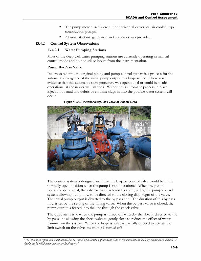
Incorporated into the original piping and pump control system is a process for the automatic divergence of the initial pump output to a by-pass line. There was evidence that this automatic start procedure was operational or could be made operational at the newer well stations. Without this automatic process in place, injection of mud and debris or chlorine slugs in into the potable water system will occur.
Figure 13-2 – Operational By-Pass Valve at Station Y-21A
The control system is designed such that the by-pass control valve would be in the normally open position when the pump is not operational. When the pump becomes operational, the valve actuator solenoid is energized by the pump control system allowing pump flow to be directed to the closing diaphragm of the valve. The initial pump output is diverted to the by pass line. The duration of this by pass flow is set by the setting of the timing valve. When the by-pass valve is closed, the pump output is forced into the line through the check valve.
The opposite is true when the pump is turned off whereby the flow is diverted to the by-pass line allowing the check valve to gently close to reduce the effect of water hammer on the system. When the by-pass valve is partially opened to actuate the limit switch on the valve, the motor is turned off.
Vol 1 - Chapter 13 SCADA and Control Assessment
“This is a draft report and is not intended to be a final representation of the work done or recommendations made by Brown and Caldwell. It should not be relied upon; consult the final report.” 13-10
At Station Y-21A, the vent line for the by-pass valve solenoid was found to be plugged. This was cleared and the timing valves adjusted such that the by-pass line operated to divert the initial flow. The closing sequence did not operate as planned as the limit switch adjustment was not correctly calibrated. During the duration that the pump is not operational, the by-pass valve is in the open position. This leaves a direct line to the well from the exterior for vermin to enter. It is highly recommended that this line be screened.
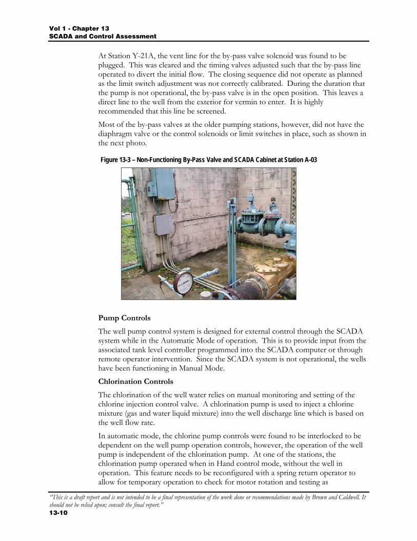
Most of the by-pass valves at the older pumping stations, however, did not have the diaphragm valve or the control solenoids or limit switches in place, such as shown in the next photo.
Figure 13-3 – Non-Functioning By-Pass Valve and SCADA Cabinet at Station A-03
Pump Controls
The well pump control system is designed for external control through the SCADA system while in the Automatic Mode of operation. This is to provide input from the associated tank level controller programmed into the SCADA computer or through remote operator intervention. Since the SCADA system is not operational, the wells have been functioning in Manual Mode.
Chlorination Controls
The chlorination of the well water relies on manual monitoring and setting of the chlorine injection control valve. A chlorination pump is used to inject a chlorine mixture (gas and water liquid mixture) into the well discharge line which is based on the well flow rate.
In automatic mode, the chlorine pump controls were found to be interlocked to be dependent on the well pump operation controls, however, the operation of the well pump is independent of the chlorination pump. At one of the stations, the chlorination pump operated when in Hand control mode, without the well in operation. This feature needs to be reconfigured with a spring return operator to allow for temporary operation to check for motor rotation and testing as
Vol 1 Chapter 13 SCADA and Control Assessment
“This is a draft report and is not intended to be a final representation of the work done or recommendations made by Brown and Caldwell. It should not be relied upon; consult the final report.”
13-11
chlorination liquid could be injected into the line or the pump will attempt to pump “dry”.
Pump Instrumentation
Lack of monitoring water pressure also reduces the system effectiveness and efficiency. Since there are no control communications in place between the reservoirs and their respective pumping stations, it is impossible for the pumping stations to cycle at the proper times in order to maintain a desired reservoir level.
The following are a list of instrumentation and related devices that should be operational at every deep well water pumping station to provide a properly, safely, and efficiently operated system.
Wellhead pressure monitoring: protects the pump from excessive pressures due to valve failure or blockage. Also confirms that the pump is operating within design pressure range.
Water flow meter: used to meter total water produced and form a part of the calculation to determine system water losses.
Bypass valve solenoid: used to operate the bypass valve to purge the system at the start pump cycle.
Water flow switch: used to confirm water flow and integrate into the chlorination control logic.
Water pump starter: used to start and stop the deep well pump motor and protect from overloads. Also monitor pumps status (overload trip, on & off conditions).
Pump Motor Protector: used to provide added protection for voltage and current unbalance, over and under current, phase loss or reversal, motor over temperature with adjustable time delays.
Chlorination pump starter: used to start and stop the chlorination injection pump motor and protect it from overloads.
Chlorine supply line solenoid: used to protect the system from accidental injection of chlorine when pump is off.
Chlorine gas leak detector: used to provide local and SCADA alarm if chlorine gas is detected.
Note: The system will work properly only if the associated mechanical equipment is also operational. Most of the diaphragm actuated bypass valves require maintenance or replacement. (The assessment of the condition of mechanical equipment is not under the scope of this section).
Station Generator
The majority of the deep well water pumping stations has an emergency generator installed. In the event of a power failure, the automatic transfer switch control panel should automatically start the generator after a pre-determined delay period. The transfer switch automatically transfers the station power to the generator source. Upon power restoration, the control panel monitors for voltage stability, transfers the station back to utility power, and allows the generator to go through a cool down cycle.
Vol 1 - Chapter 13 SCADA and Control Assessment
“This is a draft report and is not intended to be a final representation of the work done or recommendations made by Brown and Caldwell. It should not be relied upon; consult the final report.” 13-12
The following are a list of recommended input points for monitoring the generator to enhance the system operation:
Generator Run / Standby Generator Fault Voltage Unbalance Power Fail Battery Voltage Fuel Tank Level Day Tank Level Transfer switch position
Note: While there are other generator and transfer switch input points that can be monitored, the list above represents the minimum necessary for effective remote monitoring by a SCADA system.
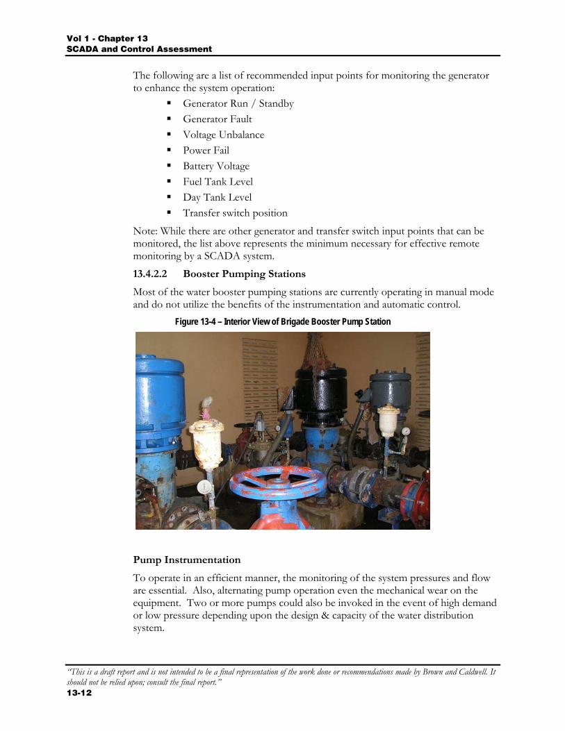
13.4.2.2 Booster Pumping Stations
Most of the water booster pumping stations are currently operating in manual mode and do not utilize the benefits of the instrumentation and automatic control.
Figure 13-4 – Interior View of Brigade Booster Pump Station
Pump Instrumentation
To operate in an efficient manner, the monitoring of the system pressures and flow are essential. Also, alternating pump operation even the mechanical wear on the equipment. Two or more pumps could also be invoked in the event of high demand or low pressure depending upon the design & capacity of the water distribution system.
Vol 1 Chapter 13 SCADA and Control Assessment
“This is a draft report and is not intended to be a final representation of the work done or recommendations made by Brown and Caldwell. It should not be relied upon; consult the final report.”
13-13
The following are a list of instrumentation and related devices that should be operational at every potable water booster pump station in order for the station to operate properly, safely and efficiently:
Inlet pressure transmitter: used to monitor pump suction pressure to avoid cavitation and provide alarming.
Outlet pressure transmitter: used to monitor head pressure for control logic and alarming.
Water flow meter: used to quantify volume of water pumped and to calculate water losses.
Water flow switch: used to confirm water flow and for control system interlocks and alarming.
Water pump starters: used to start and stop the booster pump motors and protect it from overloads. Also monitors pump motor status (overload trip, on & off conditions).
Pump Motor Protector: used to provide additional protection for conditions of over and under voltage, and phase loss or reversal.
Control interlocks between the reservoir levels and the operation of the deep well pumps and booster pumping stations were not evident. Lack of process controls and instrumentation result in the following situations:
Low or High (Overflow) reservoir level Low or No system pressure (line breakage) High system pressure
Generator
The comments regarding the generator controls as found in the section on deep well water pumping stations also apply to the water booster pump stations. Comments regarding mechanical equipment condition also apply.
13.4.2.3 Water Treatment Plant
The Ugum water treatment plant is the only water treatment facility operated by GWA. At the time of the onsite evaluation, most of the plant was being operated manually with the exception of a bubbler system that controlled the pumping of water from the finished water wet well to the reservoir. A chlorine leak detection and a few minor systems and interlocks were also found to be operational. However, the operators indicated that most of the plant was being operated manually.
Plant Instrumentation
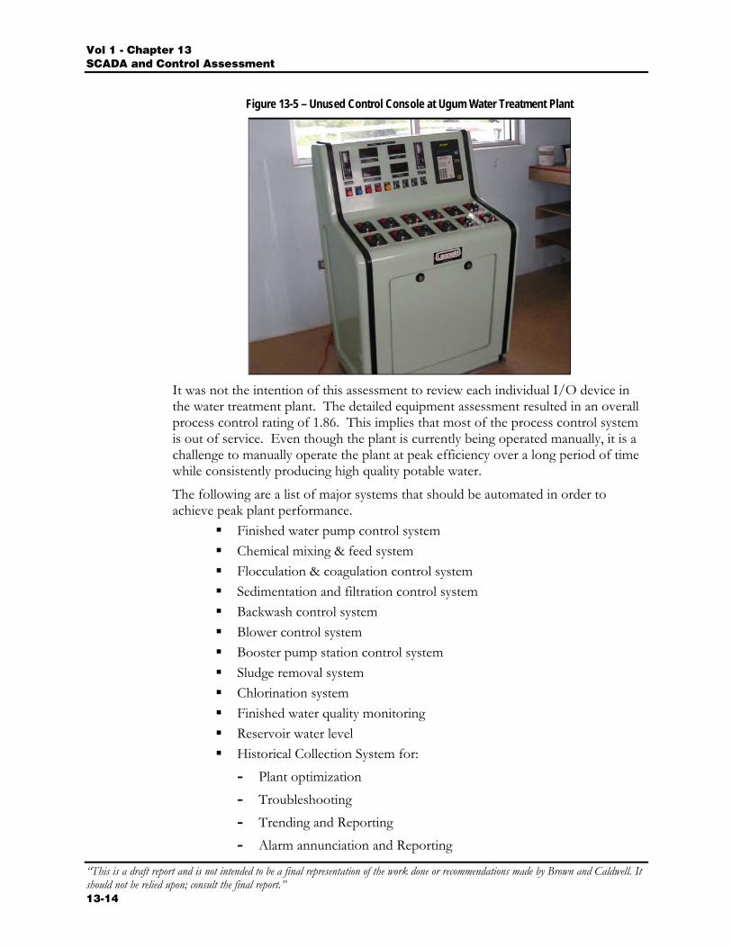
The plant has a main control room that contains four control consoles as manufactured by Leopold and six (6) programmable logic controllers (PLC). There are also remote control stations throughout the facility used for local control (example: operation of motorized valves). All of these systems were not in service.
Vol 1 - Chapter 13 SCADA and Control Assessment
“This is a draft report and is not intended to be a final representation of the work done or recommendations made by Brown and Caldwell. It should not be relied upon; consult the final report.” 13-14
Figure 13-5 – Unused Control Console at Ugum Water Treatment Plant
It was not the intention of this assessment to review each individual I/O device in the water treatment plant. The detailed equipment assessment resulted in an overall process control rating of 1.86. This implies that most of the process control system is out of service. Even though the plant is currently being operated manually, it is a challenge to manually operate the plant at peak efficiency over a long period of time while consistently producing high quality potable water.
The following are a list of major systems that should be automated in order to achieve peak plant performance.
Finished water pump control system Chemical mixing & feed system Flocculation & coagulation control system Sedimentation and filtration control system Backwash control system Blower control system Booster pump station control system Sludge removal system Chlorination system Finished water quality monitoring Reservoir water level Historical Collection System for:
- Plant optimization - Troubleshooting - Trending and Reporting - Alarm annunciation and Reporting
Vol 1 Chapter 13 SCADA and Control Assessment
“This is a draft report and is not intended to be a final representation of the work done or recommendations made by Brown and Caldwell. It should not be relied upon; consult the final report.”
13-15
In general, the local controls for the Ugum water treatment plant should be designed to operate independently (without any external inputs). However, the operation of the plant should be coordinated with the Ugum river raw water pump station and other booster pump stations and reservoir levels, which would require external communications.
Generator
The comments regarding the generator controls as found in the section on deep well potable water pumping stations also apply to the Ugum water treatment plant. Comments regarding mechanical equipment condition also apply.
13.4.2.4 Wastewater Pumping Stations
Most of the wastewater pumping stations had a Motorola SCADA RTU unit installed, however, there were a few of the newer stations such as Chaot (New), Chalan Pago 3 and 5, Machanao, etc. that were not equipped.
A few of the stations were observed to have operational radio and/or RTU modules such as at Agana Main, Asan, and Piti.
Most of the RTU cabinets were installed indoors or under the roof eave. The cabinets under the roof eave were observed to be in fair condition. Those located on the building interior faired much better.
The field wiring was installed to the cabinets; however, many were not terminated and need be traced. Masking tape was used for wire identification and many have since become brittle and have fallen off the conductor.
Pump Operation
There are two types of pumping station designs used at the GWA Pump Stations: Wet well with one or more submersible pumps Wet well with multiple centrifugal pumps located in an adjacent dry well
In general, the stations with submersible pumps had their controls modified to simple controls system consisting of wet well level detection and a pump alternator. The larger wastewater pump stations have submersible pumps located in the dry wells. In these stations it is important to have a fully functional sump pump and high dry well level float switch to provide an alarm condition in the event of a flood condition.
The minimum process control I/O, for wastewater pumping stations with multiple pumps, are as follows:
High dry well level float switch High wet well level float switch Wet well level sensor Power Failure Pump starters Generator run / standby status Redundant pump start/stop controls
Vol 1 - Chapter 13 SCADA and Control Assessment
“This is a draft report and is not intended to be a final representation of the work done or recommendations made by Brown and Caldwell. It should not be relied upon; consult the final report.” 13-16
Chlorine gas detection & control (where applicable)
The following additional process I/O devices would enhance the operation, maintenance and alarming capabilities of all types of wastewater pump stations. These devices include the following:
Communicator control monitoring (where applicable) Wet well low level indication Station Flow metering Motor moisture and winding thermal detector Motor Load and condition Motor Overload Status Phase monitoring Pump variable speed controller (where applicable) Accurate wet well level transmitter (ex: level probe) Generator fuel level Generator fuel leak detector
Most of the wastewater pumping stations use a bubbler system that provides wet well level input (dry contact) to a simple pump alternator manufactured by Time Mark (model 471 multi-stage alternator). Other level detection systems include level detection rods, ultrasonic level detectors, ball, and float level switches.
A bubbler system requires an air compressor to provide a reliable source of instrument air. The GWA maintenance staff is trained to regularly drain the condensate moisture from the air compressor tank. The second most common type of pump control was the use of float switches located in the wet well.
A bubbler system is recommended to provide wet well level input to the pump control system for most of the wastewater pumping stations since it is fairly simple in design and easy to maintain. Wet well level indication can also be determined with the installation of a level gauge used in conjunction with a pressure transducer to provide an analog level indication to the SCADA system.
It is also recommended to install double air compressors with an air reserve tank. Also recommended is the installation of a high level float switch in every wet well. If the bubbler system fails, the high-level float switch will not only signal an alarm condition but also initiate a timed pump down cycle.
Generator
Most of the wastewater pumping stations were equipped with an emergency generator. The operation of the generator is similar to that covered for the water pumping stations.
The following is a list of recommended additional input points for monitoring the generator:
Generator Run/Standby Generator Fail
Vol 1 Chapter 13 SCADA and Control Assessment
“This is a draft report and is not intended to be a final representation of the work done or recommendations made by Brown and Caldwell. It should not be relied upon; consult the final report.”
13-17
Voltage Unbalance Battery Voltage Fuel tank level Day Tank level Transfer switch position
Note: While there are many more generator and transfer switch input points that can be monitored, the list above represents the minimum necessary for effective remote monitoring by a SCADA system.
13.4.2.5 Wastewater Treatment Plants
The control systems were assessed at all of the wastewater treatment plants. In general, all of the plants operational functions were being operated manually with the exception of the wet well level control and associated motor alternation and control.
Even though the plants can currently being operated manually, it is a challenge to operate the plants at peak efficiency. The automated systems enhance plants operating at peak performance with minimal manpower.
Plant Controls
The following are a list of the major unit process areas that require properly operating automation systems in order to achieve peak plant performance.
Headworks Clarifiers Pump gallery (sludge, recirculation, scum pumps, etc) Centrifuges Blowers Digesters Odor Control Systems Chlorination Effluent Pumps Plant Generator
Not all of the systems listed above apply to all wastewater treatment plants.
In general, the control systems for the wastewater treatment plants should be designed to operate independently (without any external inputs). However the operation of the plants need be monitored from a central SCADA system since none of the wastewater treatment plants have a 24-hour staff. A communication system to a central SCADA system is necessary to accomplish this. In addition, it is advantageous to have each treatment plant monitor the status of all pumping stations associated with that plant.
Vol 1 - Chapter 13 SCADA and Control Assessment
“This is a draft report and is not intended to be a final representation of the work done or recommendations made by Brown and Caldwell. It should not be relied upon; consult the final report.” 13-18
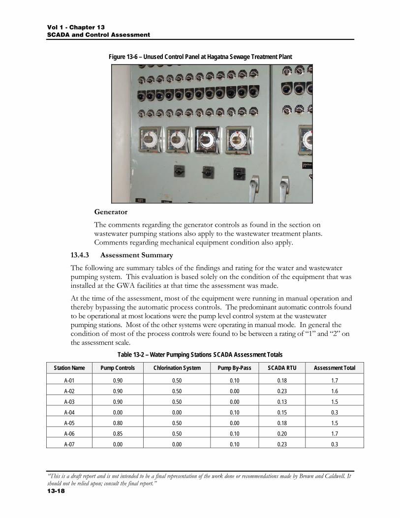
Figure 13-6 – Unused Control Panel at Hagatna Sewage Treatment Plant
Generator
The comments regarding the generator controls as found in the section on wastewater pumping stations also apply to the wastewater treatment plants. Comments regarding mechanical equipment condition also apply.
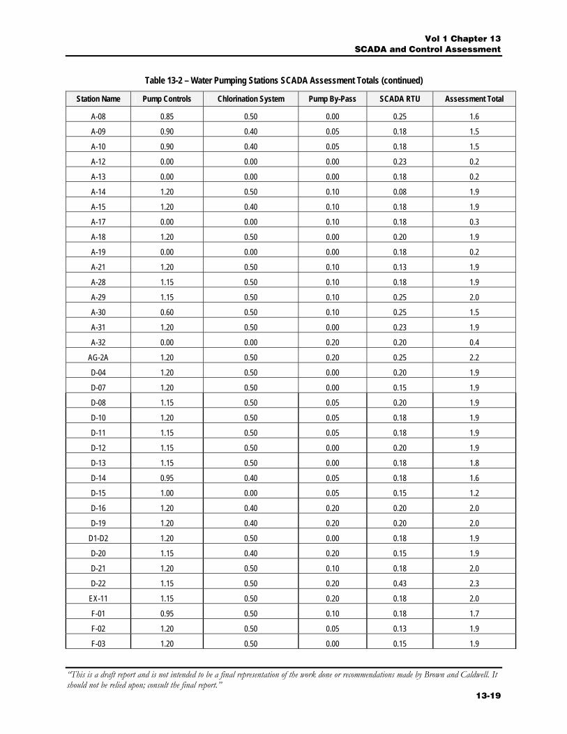
13.4.3 Assessment Summary
The following are summary tables of the findings and rating for the water and wastewater pumping system. This evaluation is based solely on the condition of the equipment that was installed at the GWA facilities at that time the assessment was made.
At the time of the assessment, most of the equipment were running in manual operation and thereby bypassing the automatic process controls. The predominant automatic controls found to be operational at most locations were the pump level control system at the wastewater pumping stations. Most of the other systems were operating in manual mode. In general the condition of most of the process controls were found to be between a rating of “1” and “2” on the assessment scale.
Table 13-2 – Water Pumping Stations SCADA Assessment Totals
Station Name Pump Controls Chlorination System Pump By-Pass SCADA RTU Assessment Total
A-01 0.90 0.50 0.10 0.18 1.7
A-02 0.90 0.50 0.00 0.23 1.6
A-03 0.90 0.50 0.00 0.13 1.5
A-04 0.00 0.00 0.10 0.15 0.3
A-05 0.80 0.50 0.00 0.18 1.5
A-06 0.85 0.50 0.10 0.20 1.7
A-07 0.00 0.00 0.10 0.23 0.3
Vol 1 Chapter 13 SCADA and Control Assessment
“This is a draft report and is not intended to be a final representation of the work done or recommendations made by Brown and Caldwell. It should not be relied upon; consult the final report.”
13-19
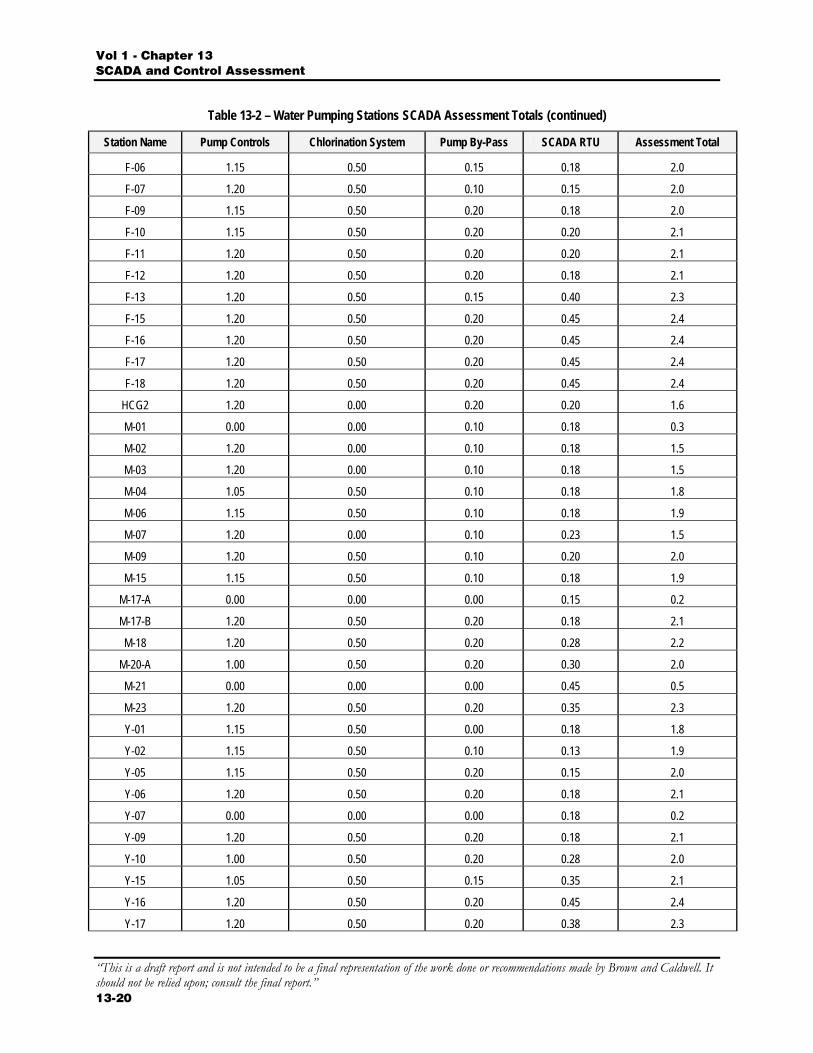
Table 13-2 – Water Pumping Stations SCADA Assessment Totals (continued)
Station Name Pump Controls Chlorination System Pump By-Pass SCADA RTU Assessment Total
A-08 0.85 0.50 0.00 0.25 1.6
A-09 0.90 0.40 0.05 0.18 1.5
A-10 0.90 0.40 0.05 0.18 1.5
A-12 0.00 0.00 0.00 0.23 0.2
A-13 0.00 0.00 0.00 0.18 0.2
A-14 1.20 0.50 0.10 0.08 1.9
A-15 1.20 0.40 0.10 0.18 1.9
A-17 0.00 0.00 0.10 0.18 0.3
A-18 1.20 0.50 0.00 0.20 1.9
A-19 0.00 0.00 0.00 0.18 0.2
A-21 1.20 0.50 0.10 0.13 1.9
A-28 1.15 0.50 0.10 0.18 1.9
A-29 1.15 0.50 0.10 0.25 2.0
A-30 0.60 0.50 0.10 0.25 1.5
A-31 1.20 0.50 0.00 0.23 1.9
A-32 0.00 0.00 0.20 0.20 0.4
AG-2A 1.20 0.50 0.20 0.25 2.2
D-04 1.20 0.50 0.00 0.20 1.9
D-07 1.20 0.50 0.00 0.15 1.9
D-08 1.15 0.50 0.05 0.20 1.9
D-10 1.20 0.50 0.05 0.18 1.9
D-11 1.15 0.50 0.05 0.18 1.9
D-12 1.15 0.50 0.00 0.20 1.9
D-13 1.15 0.50 0.00 0.18 1.8
D-14 0.95 0.40 0.05 0.18 1.6
D-15 1.00 0.00 0.05 0.15 1.2
D-16 1.20 0.40 0.20 0.20 2.0
D-19 1.20 0.40 0.20 0.20 2.0
D1-D2 1.20 0.50 0.00 0.18 1.9
D-20 1.15 0.40 0.20 0.15 1.9
D-21 1.20 0.50 0.10 0.18 2.0
D-22 1.15 0.50 0.20 0.43 2.3
EX-11 1.15 0.50 0.20 0.18 2.0
F-01 0.95 0.50 0.10 0.18 1.7
F-02 1.20 0.50 0.05 0.13 1.9
F-03 1.20 0.50 0.00 0.15 1.9
Vol 1 - Chapter 13 SCADA and Control Assessment
“This is a draft report and is not intended to be a final representation of the work done or recommendations made by Brown and Caldwell. It should not be relied upon; consult the final report.” 13-20
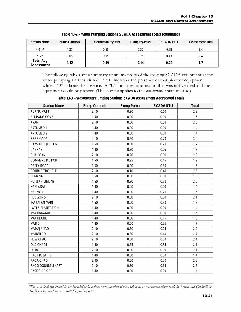
Table 13-2 – Water Pumping Stations SCADA Assessment Totals (continued)
Station Name Pump Controls Chlorination System Pump By-Pass SCADA RTU Assessment Total
F-06 1.15 0.50 0.15 0.18 2.0
F-07 1.20 0.50 0.10 0.15 2.0
F-09 1.15 0.50 0.20 0.18 2.0
F-10 1.15 0.50 0.20 0.20 2.1
F-11 1.20 0.50 0.20 0.20 2.1
F-12 1.20 0.50 0.20 0.18 2.1
F-13 1.20 0.50 0.15 0.40 2.3
F-15 1.20 0.50 0.20 0.45 2.4
F-16 1.20 0.50 0.20 0.45 2.4
F-17 1.20 0.50 0.20 0.45 2.4
F-18 1.20 0.50 0.20 0.45 2.4
HCG2 1.20 0.00 0.20 0.20 1.6
M-01 0.00 0.00 0.10 0.18 0.3
M-02 1.20 0.00 0.10 0.18 1.5
M-03 1.20 0.00 0.10 0.18 1.5
M-04 1.05 0.50 0.10 0.18 1.8
M-06 1.15 0.50 0.10 0.18 1.9
M-07 1.20 0.00 0.10 0.23 1.5
M-09 1.20 0.50 0.10 0.20 2.0
M-15 1.15 0.50 0.10 0.18 1.9
M-17-A 0.00 0.00 0.00 0.15 0.2
M-17-B 1.20 0.50 0.20 0.18 2.1
M-18 1.20 0.50 0.20 0.28 2.2
M-20-A 1.00 0.50 0.20 0.30 2.0
M-21 0.00 0.00 0.00 0.45 0.5
M-23 1.20 0.50 0.20 0.35 2.3
Y-01 1.15 0.50 0.00 0.18 1.8
Y-02 1.15 0.50 0.10 0.13 1.9
Y-05 1.15 0.50 0.20 0.15 2.0
Y-06 1.20 0.50 0.20 0.18 2.1
Y-07 0.00 0.00 0.00 0.18 0.2
Y-09 1.20 0.50 0.20 0.18 2.1
Y-10 1.00 0.50 0.20 0.28 2.0
Y-15 1.05 0.50 0.15 0.35 2.1
Y-16 1.20 0.50 0.20 0.45 2.4
Y-17 1.20 0.50 0.20 0.38 2.3
Vol 1 Chapter 13 SCADA and Control Assessment
“This is a draft report and is not intended to be a final representation of the work done or recommendations made by Brown and Caldwell. It should not be relied upon; consult the final report.”
13-21
Table 13-2 – Water Pumping Stations SCADA Assessment Totals (continued)
Station Name Pump Controls Chlorination System Pump By-Pass SCADA RTU Assessment Total
Y-21-A 1.25 0.50 0.30 0.38 2.4
Y-23 1.05 0.65 0.25 0.43 2.4 Total Avg
Assessment 1.12 0.49 0.14 0.22 1.7
The following tables are a summary of an inventory of the existing SCADA equipment at the water pumping stations visited. A “1” indicates the presence of that piece of equipment while a “0” indicate the absence. A “U” indicates information that was not verified and the equipment could be present. (This coding applies to the wastewater stations also).
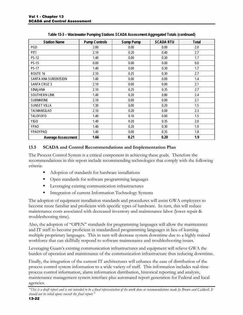
Table 13-3 – Wastewater Pumping Stations SCADA Assessment Aggregated Totals
Station Name Pump Controls Sump Pump SCADA RTU Total AGANA MAIN 2.10 0.20 0.60 2.9 ALUPANG COVE 1.50 0.00 0.00 1.5 ASAN 2.10 0.00 0.50 2.6 ASTUMBO 1 1.40 0.00 0.00 1.4 ASTUMBO 2 1.40 0.00 0.00 1.4 BARRIGADA 2.10 0.20 0.70 3.0 BAYSIDE EJECTOR 1.50 0.00 0.20 1.7 CABRAS 1.40 0.30 0.05 1.8 CHALIGAN 2.10 0.20 0.00 2.3 COMMERCIAL PORT 1.50 0.25 0.15 1.9 DAIRY ROAD 1.50 0.00 0.30 1.8 DOUBLE TROUBLE 2.10 0.10 0.40 2.6 FEMA 96 1.50 0.00 0.00 1.5 FUJITA (TUMON) 1.50 0.20 0.30 2.0 HAFI ADAI 1.40 0.00 0.00 1.4 HARMON 1.40 0.00 0.20 1.6 HUEGON 5 2.10 0.00 0.00 2.1 INARAJAN MAIN 1.50 0.00 0.30 1.8 LATTE PLANTATION 1.40 0.00 0.00 1.4 MACHANANAO 1.40 0.20 0.00 1.6 MACHECHE 1.40 0.00 0.15 1.6 MAITE 1.40 0.00 0.25 1.7 MAMAJANAO 2.10 0.20 0.25 2.6 MANGILAO 2.10 0.20 0.40 2.7 NEW CHAOT 2.10 0.30 0.00 2.4 OLD CHAOT 1.50 0.25 0.35 2.1 ORDOT 2.10 0.00 0.00 2.1 PACIFIC LATTE 1.40 0.00 0.00 1.4 PAGA CHAO 2.00 0.00 0.30 2.3 PAGO DOUBLE SHAFT 2.10 0.20 0.35 2.7 PASEO DE ORD 1.40 0.00 0.00 1.4
Vol 1 - Chapter 13 SCADA and Control Assessment
“This is a draft report and is not intended to be a final representation of the work done or recommendations made by Brown and Caldwell. It should not be relied upon; consult the final report.” 13-22
Table 13-3 – Wastewater Pumping Stations SCADA Assessment Aggregated Totals (continued)
Station Name Pump Controls Sump Pump SCADA RTU Total PGD 2.00 0.00 0.00 2.0 PITI 2.10 0.20 0.40 2.7 PS-12 1.40 0.00 0.30 1.7 PS-15 0.00 0.00 0.00 0.0 PS-17 1.40 0.00 0.30 1.7 ROUTE 16 2.10 0.25 0.30 2.7 SANTA ANA SUBDIVISION 1.40 0.00 0.00 1.4 SANTA CRUZ 3 2.10 0.00 0.00 2.1 SINAJANA 2.10 0.25 0.35 2.7 SOUTHERN LINK 1.40 0.20 0.80 2.4 SUBMARINE 2.10 0.00 0.00 2.1 SUNSET VILLA 1.30 0.00 0.20 1.5 TAI MANGILAO 2.10 0.20 0.00 2.3 TALOFOFO 1.40 0.10 0.00 1.5 YIGO 1.40 0.20 0.35 2.0 YPAO 1.40 0.20 0.30 1.9 YPAOYPAO 1.40 0.00 0.35 1.8
Average Assessment 1.66 0.21 0.20 1.9
13.5 SCADA and Control Recommendations and Implementation Plan
The Process Control System is a critical component in achieving these goals. Therefore the recommendations in this report include recommending technologies that comply with the following criteria:
Adoption of standards for hardware installations Open standards for software programming languages Leveraging existing communication infrastructures Integration of current Information Technology Systems
The adoption of equipment installation standards and procedures will assist GWA employees to become more familiar and proficient with specific types of hardware. In turn, this will reduce maintenance costs associated with decreased inventory and maintenance labor (lower repair & troubleshooting time).
Also, the adoption of “OPEN” standards for programming languages will allow the maintenance and IT staff to become proficient in standardized programming languages in lieu of learning multiple proprietary languages. This in turn will decrease system downtime due to a highly trained workforce that can skillfully respond to software maintenance and troubleshooting issues.
Leveraging Guam’s existing communication infrastructures and equipment will relieve GWA the burden of operation and maintenance of the communication infrastructure thus reducing downtime.
Finally, the integration of the current IT architectures will enhance the ease of distribution of the process control system information to a wide variety of staff. This information includes real-time process control information, alarm information distribution, historical reporting and analysis, maintenance management system interface plus automated report generation for Federal and local agencies.
Vol 1 Chapter 13 SCADA and Control Assessment
“This is a draft report and is not intended to be a final representation of the work done or recommendations made by Brown and Caldwell. It should not be relied upon; consult the final report.”
13-23
These four components will significantly assist in meeting Guam’s vision for growth and development in a sustainable manner and enhance their ability to comply with all Federal and local environmental and safety regulations.
To achieve the objectives of improved efficiency and reduced operational costs, the following are recommended.
Phase 1
Based on the observations and preliminary testing, resurrecting the existing Motorola SCADA System is recommended for the following reasons:
Approximately 10 to 20% of the RTU units are operational or can be with relatively minor testing.
Components of the RTU units that are not functional or repairable will either be used for parts or discarded. There will be a number of these spare units.
All batteries need be replaced with new. One of the existing MOSCAD-L units could be converted to a field interface
unit (FIU) for the entire SCADA system. A personal computer (PC) with SCADA software could be used as the base
station to receive the status of the water and wastewater system. Off the shelf software such as that manufactured by Wonderware or Intellution
could be used in the PC. The communication system is the same as that used by the Fire, Police, and
other emergency agencies and is owned and operated by Gov Guam. Programming of the software for GWA operation is necessary, as in any SCADA
system. Phase 2
During the second phase of the SCADA installation, the revised SCADA system would be modified to accommodate the use of multiple users on a system LAN network. This is projected to be within the next five years as the system is expanded.
13.5.1 Local Process Control Improvement Recommendations
This section includes general process control equipment recommendations including design standards.
Standardization of Automation Devices and Design
A wide variety of manufacturers and equipment that perform identical functions currently exists in the various types of GWA installations. This occurred naturally over several years of operation and maintenance. Unfortunately, it is costly for GWA to maintain and troubleshoot an adequate reserve supply of replacement parts due to the wide variety of manufacturers and designs. Therefore it is recommended to select a standard device or “family of devices” for each process control component as well as standardize on the design schematic and wiring diagrams.
Simple design – While complex systems are available in the market today, it may not be the best solution for GWA. It was observed that many of the electronic devices and wiring methods had failed. Instead these systems were bypassed and other more simple systems
Vol 1 - Chapter 13 SCADA and Control Assessment
“This is a draft report and is not intended to be a final representation of the work done or recommendations made by Brown and Caldwell. It should not be relied upon; consult the final report.” 13-24
were installed. The most common example is an electronic level sensor replaced with a simple bubbler or float system. Some devices will include electronics, however they should be industrial rated and suitable for a harsh environment.
Manufacturer selection criteria – The manufacturer of the automation device should be a recognized vendor with local representation of automation products with a large installed base with parts readily available in stock. The manufacturer should demonstrate a track record of support and supply of replacement stock over a long period of time. Unfortunately these criteria may eliminate some of the new companies with new products. GWA will have to weigh the use to their products against the risk of loss of long-term support.
13.5.2 Local Process Control Requirements
Many of the sites had magnetic relays, timers, pump alternators and other “hard wired” components that composed the local process control functions. While these systems operate effectively, they usually only control the “core” function of the site. However, the complexity of the “hard wired” systems increases dramatically when additional functions are added to the control systems. Therefore, a critical threshold is reached whereby it is no longer feasible to operate a site using traditional “hard wired’ components. As the number of inputs and outputs at a site increase, the complexity of the wiring increases dramatically. Troubleshooting the wiring becomes difficult and complex.
Programmable Logic Controllers and Remote Telemetry Units are designed to replace complex “hard-wired” control systems. In addition, most are capable of a direct connection to a telemetry system or have a telemetry system built into their architecture.
Programmable Logic Controllers (PLC) and Remote Telemetry Units (RTU) both perform process logic electronically. RTU's tend to be designed to perform specialized functions and have limited process logic capabilities and are therefore proprietary in nature. RTU's also offer additional capabilities such as built-in communication systems, radio and modem equipment. RTU’s are usually more economical when compared to PLCs.
In contrast PLCs tend to be more complex and expensive yet offer versatility and scalability. PLCs usually do not have built-in communication systems and usually require an external radio or modem. A good example of use of an RTU would be in remote pumping stations while PLCs would be used in a treatment plant. However, recently many PLC manufacturers have reduced the size and price of some of their PLC family members to compete with RTU manufacturers. At the same time, the PLC manufacturers have been able to retain many of the capabilities of their traditional PLCs.
The PLC/RTU offers a high I/O density so that the unit does not have a large footprint. The typical I/O density per I/O module is as follows:
Digital Inputs – 16 (non-isolated) Digital Input – 8 inputs (isolated) Analog Input – 4 inputs Relay Output – 8 outputs (isolated and non-isolated) Analog Output – 2 outputs
Vol 1 Chapter 13 SCADA and Control Assessment
“This is a draft report and is not intended to be a final representation of the work done or recommendations made by Brown and Caldwell. It should not be relied upon; consult the final report.”
13-25
The PLC/RTU should have the capability to add additional I/O inputs and outputs without having to replace the entire unit. The hardware should have the ability to be expanded to accept up to 16 I/O modules.
The PLC/RTU should support remote access for remote configuration, programming & troubleshooting. This should include full function capabilities using various communication methods.
The PLC/RTU should support an open logic programming software product. This will allow GWA to train the staff on the use of one programming package that has the ability to program the processors located in remote pumping stations as well as the processors located in the treatment plants.
13.5.3 Operations and Maintenance Recommendations
A detailed training program should be initiated and the training will vary depending on the job responsibility of each staff member. In general there are four training classifications:
Operators Maintenance Information Technology Management
Operator training includes the basic operation of the device, hardware or software if the operator’s normal job functions require direct interaction with the product. For example, an operator should understand the process functions whenever a PLC logic program is invoked. However, the operator is not required to know how to program the PLC. The training should include “hands-on” working with the process and equipment. Testing is also a necessary portion of the training program in order to determine the level of operator competence. Regular refresher training courses and testing assures that the operators maintain comprehension of the system and continues to operate the systems properly.
Maintenance training includes all the topics presented to the operators plus a more in-depth training on the actual installation. This includes wiring, terminations, processors, modules, power supplies, calibration and testing. It also includes detailed training on PLC programming, troubleshooting and monitoring. All training should be “hands-on” in both the classroom and at actual field installations. In general the GWA maintenance staff should be thoroughly trained so that they could troubleshoot, replace hardware and load PLC/RTU logic without requiring outside assistance. Testing is also an important portion of the training program to determine the level of competence. Regular refresher training courses and testing assures that the GWA maintenance staff maintains a high level of competence to be able to maintain the systems properly.
IT staff training includes all of the topics for operators and some of the general topics provided to the maintenance staff. (Detailed PLC programming is not necessarily a job responsibility required by the IT staff.) In addition, the IT staff should be thoroughly trained in the network infrastructure, hardware (servers & workstations) and all software programs running as part of the process control system. The IT staff should be trained on performing backup and restore of the programs and communication troubleshooting. The IT staff should also be trained on report generation.
Vol 1 - Chapter 13 SCADA and Control Assessment
“This is a draft report and is not intended to be a final representation of the work done or recommendations made by Brown and Caldwell. It should not be relied upon; consult the final report.” 13-26
The GWA management staff should be trained on the overall concept of the SCADA and control systems as well as thoroughly educated on the function and capabilities of each hardware and software component. Detailed management training should be performed on all aspects of historical trending, analysis, report generation, alarming and performance monitoring along with all other types of administrative capabilities of the SCADA system.
13.5.4 GWA Maintenance Equipment Requirements
GWA maintenance staff should be equipped with the proper tools and instrumentation for calibration of the instrumentation. In addition the staff should have a minimum of two ruggedized notebooks that have the PLC/RTU programming software loaded along with a copy of all PLC logic programs.
GWA should maintain an adequate supply of replacement parts in stock.
13.5.5 Site Security and Intrusion Detection Security Monitoring System
Intrusion detection - GWA remote stations have experienced a high degree of vandalism and unauthorized intrusion. Intrusion detection devices such as motion detectors, magnetic door detectors, infrared light beams, etc should be installed at each remote location for monitoring purposes. The intrusion will be displayed as an alarm.
13.5.6 SCADA System Communication Improvement Recommendations
SCADA systems require communications between the SCADA system and the remote PLCs or RTU’s. There are two main categories of communication that are currently in use today: Hard-wired and wireless.
13.5.6.1 Hard-Wired Technologies
Hard-wired technologies include the following types of installations:
Private Communication Systems
A private communication system would require GWA to install wiring between each of the sites and connect them to the main administration building. Since this is extremely expensive, it will not be considered as an option.
Public Communication Systems
Guam Telephone Authority (GTA) provides a hard-wired public communication system that serves the island. Traditionally the copper telephone systems were somewhat unreliable and provided a low data connection speed. However, recently GTA has installed four fiber optic rings on Guam: Northern ring, Central ring, Tumon ring and Southern ring. This ring will provide high-speed access for data transmission. At the time of this assessment report, approximately 99% of GTA’s telephone system is installed underground. Telephone terminal boxes were observed to be located in close proximity of many of the water and wastewater pumping station locations.
13.5.6.2 Current Wireless Technologies
This assessment includes the radio communication system as part of the definition of the SCADA system. Therefore this section includes a discussion on the types of radio or wireless systems available today.
Vol 1 Chapter 13 SCADA and Control Assessment
“This is a draft report and is not intended to be a final representation of the work done or recommendations made by Brown and Caldwell. It should not be relied upon; consult the final report.”
13-27
The following is a list of the four main wireless technologies that are commonly used with SCADA systems today:
Licensed radio (800 Mhz, UHF & VHF) Unlicensed radio (Spread Spectrum) Cellular communications Satellite communications
While other wireless communication systems are available, such as microwave, they are too expensive, too specialized or not widely used in today’s SCADA applications. The following are a list of characteristics for each type of communication system:
Licensed radios
Low data throughput: 1.2 kbps to 9.6 kbps FCC License Required – Government of Guam Existing Government of Guam Trunked Radio System already in place Minimal operation cost
Unlicensed radios
High data throughput: 2-3 Mbps or higher Requires line of sight High susceptibility to interference (EX: wireless residential phones) Subject to signal loss during rain Usually mount antennas on towers Owner maintains equipment & infrastructure High initial installation cost Minimal operation cost
Cellular communications
Medium data throughput: 153 - 384 kbps (depending on selected technology)
Non-line of sight Requires monthly service fee per site Service provider maintains infrastructure Owner maintains radio Moderate initial installation cost
Satellite communications
Low data throughput Usually only transmits data using “Report on Exception” Subject to loss of signal (rain fade) Service provider maintains infrastructure Owner maintains radio Moderate initial installation cost
Vol 1 - Chapter 13 SCADA and Control Assessment
“This is a draft report and is not intended to be a final representation of the work done or recommendations made by Brown and Caldwell. It should not be relied upon; consult the final report.” 13-28
High service provider cost
While all four technologies are currently used with SCADA systems, this assessment report recommends using the Government of Guam Trunked Radio System during the initial phases, for the following reasons:
Use existing infrastructure (does not require owner to build infrastructure)
Low initial cost of installation Low cost of ownership since Gov Guam owns and operates the
infrastructure High reliability used for emergency services Acceptable signal strengths Two-way communication within GWA Talk group Key personnel can interface with Police and Fire for coordination
13.5.7 SCADA System Improvement Recommendations
One of the key functions of a SCADA system is alarm annunciation. If alarm conditions are detected early then the maintenance or operation staff could be dispatched to make repairs and avoid more serious damage to equipment. A SCADA alarm system could also assist to avoid wastewater spills and loss of potable water supply to consumers. There are many other benefits that result from the alarm function of a SCADA system.
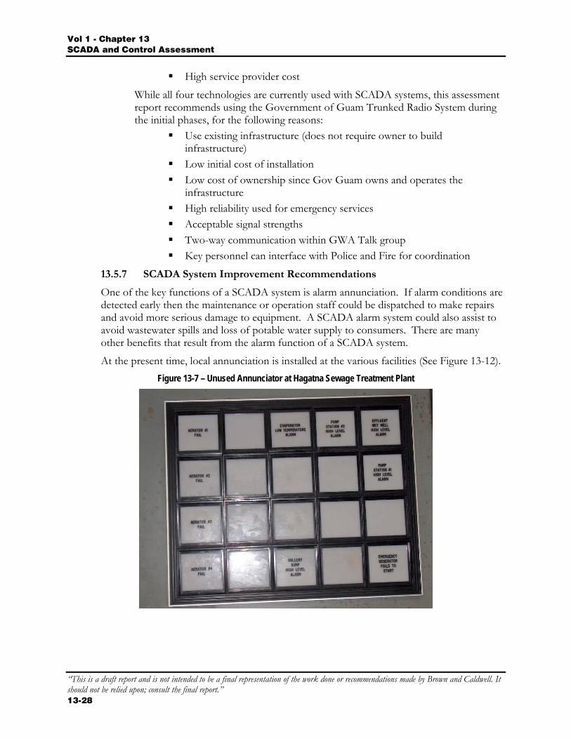
At the present time, local annunciation is installed at the various facilities (See Figure 13-12). Figure 13-7 – Unused Annunciator at Hagatna Sewage Treatment Plant
Vol 1 Chapter 13 SCADA and Control Assessment
“This is a draft report and is not intended to be a final representation of the work done or recommendations made by Brown and Caldwell. It should not be relied upon; consult the final report.”
13-29
13.5.7.1 SCADA Supervisory Function
A SCADA system Supervisory Function is designed to operate in a supervisory capacity only. It is not designed for continuous process logic which is a function of the PLC or RTU. The SCADA communicates continually with the PLC/RTU processors and the process logic in the PLC/RTU should continue to operate normally in the event that the SCADA system computer ceases communication with the PLC/RTU. With this architecture in mind, the SCADA system would not contain logic that would continually coordinate booster pumps for example. This task would be the responsibility of the PLC.
13.5.7.2 SCADA Data Acquisition Function
A SCADA system Data Acquisition Function is designed to acquire data from the remote PLCs and RTU’s. The data is put into a real-time database. The database is used to provide data to the following software applications:
Graphical Objects on the display screen Real-time trending Historical collection applications Real-time reporting applications Voice, e-mail and telephone alarm annunciation Other databases via ODBC connections OPC connections to other applications
13.5.7.3 SCADA Clients
The location of the SCADA clients is based on the job responsibilities of the GWA employee to determine if SCADA access is required. A SCADA Client is defined as a remote display terminal that allows the viewing and operation of the SCADA system screens. A SCADA client can be located on the existing GWA network, a plant network or as a wireless connection. The following is a list of suggested SCADA client locations:
GWA dispatch office Water division supervisor office Wastewater division supervisor office IT manager office GWA general manager office GWA compliance manager office GWA operations manager office Ugum water treatment plant control room Agana wastewater treatment plant control room Northern wastewater treatment plant control room
Vol 1 - Chapter 13 SCADA and Control Assessment
“This is a draft report and is not intended to be a final representation of the work done or recommendations made by Brown and Caldwell. It should not be relied upon; consult the final report.” 13-30
13.5.7.4 Central Command Location
In addition to the SCADA client locations as listed above, it is recommended to locate at least two SCADA clients in a secure location that would serve as a central command post during storms or other emergencies. It is preferable that this Central Command center is co-located inside or adjacent to the IT department that contains the “core hardware and software”. The Central Command location can also serve as a central control room if desired during normal operations. However, it should be noted that the recommended SCADA architecture is based on a distributed workforce and therefore a continually manned control center is not an absolute necessity. The Central Command hardware shall be supplied with power from UPS units and also an emergency generator.
13.5.7.5 SCADA Maintenance & Development Location
The Central Command post shall also serve a dual purpose as the SCADA maintenance location by the GWA staff. It shall be also used by the SCADA installation contractors for software installation, testing, training and final acceptance.
13.5.7.6 SCADA Security
The SCADA system serves as the monitoring and communication backbone for a utility and must be secure from unauthorized access at all times. Security can be achieved by implementing one or more of the following security features as deemed necessary to protect GWA operations at all times.
Hardware firewall with virus signature analysis Anti-virus protection Windows security Network encryption VPN wireless connections Dynamic IP addressing Dynamic welch codes Secure site connections Lock & Key
13.5.8 Information Management System Improvements
13.5.8.1 GWA IT Department Requirements
It is recommended that the core hardware and software components of the SCADA system reside in the Information Technology (IT) Department facility. The term “core hardware and software” refers to a central location that serves as a central repository of SCADA information and has the ability to monitor all installations, generate alarms, provide trending information, collect historical data, generate administrative reports and provide facility operational metrics. The core components communicate with other SCADA servers such as those found in the water and wastewater treatment plants and monitor their operations. Finally, the core hardware and software will perform general system duties such as adjust and monitor the reservoir level setpoints and associated alarming.
Vol 1 Chapter 13 SCADA and Control Assessment
“This is a draft report and is not intended to be a final representation of the work done or recommendations made by Brown and Caldwell. It should not be relied upon; consult the final report.”
13-31
The assessment team visited the GWA IT manager and discussed the SCADA requirements as presented in this section.
13.5.8.2 Data Highway
The main wireless connection will arrive into the SCADA system from the IT department’s switches. The data could arrive via any one or more of the following data highways:
GTA Cellular radio Internet T-1 Internet DSL (SDSL or ADSL) Microwave
All data should pass through a hardware firewall that support virus signature scanning and provides front line security protection to all computers behind the firewall. The data should then pass through a router to isolate SCADA traffic from GWA administration traffic.
13.5.8.3 Hardware Location
All SCADA hardware should be located in two dedicated 19-inch enclosed racks. The racks should be located in a temperature and humidity controlled room and be provided with Uninterruptible Power and back-up generator.
13.5.8.4 Thin SCADA Clients
The SCADA clients will be located on the existing GWA LAN and operate as single board Thin Client computers that have terminal server sessions on the terminal server computer located in the IT computer room. The SCADA thin clients do not require any added software or maintenance since all software applications and licenses are loaded and maintained on the terminal server. This significantly reduces any maintenance requirements of client PCs. Thin client single board computers do not have any moving parts and therefore have a significantly longer hardware life span. In addition, thin clients require very little IT personnel maintenance since all maintenance is performed in the server rack located in the IT department.
13.5.8.5 Printers
Network printers are to be installed on the existing GWA network. Reports are to be printed from the SCADA reporting software.
13.5.8.6 IT Staff Responsibilities
The GWA staff will be responsible for maintenance of all the equipment located in the two SCADA racks. In addition the IT staff is responsible for backup of data and applications on a regular basis. High-density backup tape drives will be specified as part of the hardware server requirements.
In addition, the IT staff will be highly trained on all applications loaded on the SCADA servers with the exception of PLC programming. At least one person in the IT staff should be trained on the SCADA software and communication drivers.