Embed Size (px)
Citation preview
LearningExpectations
398 Unit E ©P
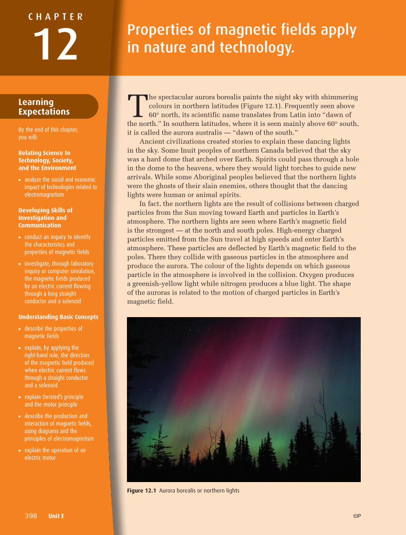
The spectacular aurora borealis paints the night sky with shimmering colours in northern latitudes (Figure 12.1). Frequently seen above 60° north, its scientific name translates from Latin into “dawn of
the north.” In southern latitudes, where it is seen mainly above 60° south, it is called the aurora australis — “dawn of the south.”
Ancient civilizations created stories to explain these dancing lights in the sky. Some Inuit peoples of northern Canada believed that the sky was a hard dome that arched over Earth. Spirits could pass through a hole in the dome to the heavens, where they would light torches to guide new arrivals. While some Aboriginal peoples believed that the northern lights were the ghosts of their slain enemies, others thought that the dancing lights were human or animal spirits.
In fact, the northern lights are the result of collisions between charged particles from the Sun moving toward Earth and particles in Earth’s atmosphere. The northern lights are seen where Earth’s magnetic field is the strongest — at the north and south poles. High-energy charged particles emitted from the Sun travel at high speeds and enter Earth’s atmosphere. These particles are deflected by Earth’s magnetic field to the poles. There they collide with gaseous particles in the atmosphere and produce the aurora. The colour of the lights depends on which gaseous particle in the atmosphere is involved in the collision. Oxygen produces a greenish-yellow light while nitrogen produces a blue light. The shape of the auroras is related to the motion of charged particles in Earth’s magnetic field.
Properties of magnetic fields apply in nature and technology.
C H A P T E R
12
By the end of this chapter, you will:
Relating Science to Technology, Society, and the Environment
● analyze the social and economic impact of technologies related to electromagnetism
Developing Skills of Investigation and Communication
● conduct an inquiry to identify the characteristics and properties of magnetic fields
● investigate, through laboratory inquiry or computer simulation, the magnetic fields produced by an electric current flowing through a long straight conductor and a solenoid
Understanding Basic Concepts
● describe the properties of magnetic fields
● explain, by applying the right-hand rule, the direction of the magnetic field produced when electric current flows through a straight conductor and a solenoid
● explain Oersted’s principle and the motor principle
● describe the production and interaction of magnetic fields, using diagrams and the principles of electromagnetism
● explain the operation of an electric motor
Figure 12.1 Aurora borealis or northern lights
12-PHYSICS-11SE-Ch12.indd 39812-PHYSICS-11SE-Ch12.indd 398 7/26/10 10:04:15 AM7/26/10 10:04:15 AM
Chapter 12 Properties of magnetic fields apply in nature and technology. 399©P
Magnetic Forces and Fields
An ancient Greek legend from about 800 B.C.E. describes how the shepherd Magnes, while tending his flock, noticed that pieces of a certain type of rock were attracted to the nails on his shoes and to his metal staff. This phenomenon is called magnetism. Magnetism is the attraction or repulsion of certain materials to a magnetic material.
The Law of MagnetismPeople have always been interested in magnetism. Over time, studies of the behaviour of the magnetic rock revealed several curious effects. For example, a piece of this rock could either attract or repel another piece of rock. This effect seemed to result from two different magnetic effects, so investigators thought that there must be two different types of “magnetic ends” on the rock.
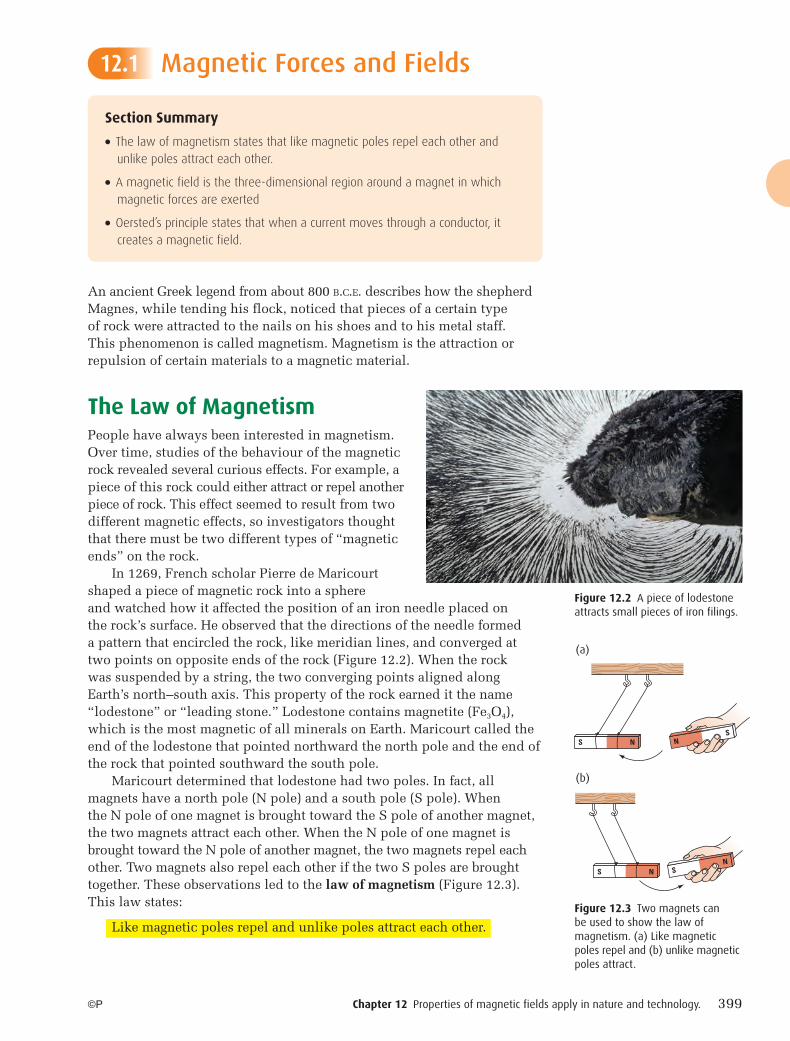
In 1269, French scholar Pierre de Maricourt shaped a piece of magnetic rock into a sphere and watched how it affected the position of an iron needle placed on the rock’s surface. He observed that the directions of the needle formed a pattern that encircled the rock, like meridian lines, and converged at two points on opposite ends of the rock (Figure 12.2). When the rock was suspended by a string, the two converging points aligned along Earth’s north–south axis. This property of the rock earned it the name “lodestone” or “leading stone.” Lodestone contains magnetite (Fe3O4), which is the most magnetic of all minerals on Earth. Maricourt called the end of the lodestone that pointed northward the north pole and the end of the rock that pointed southward the south pole.
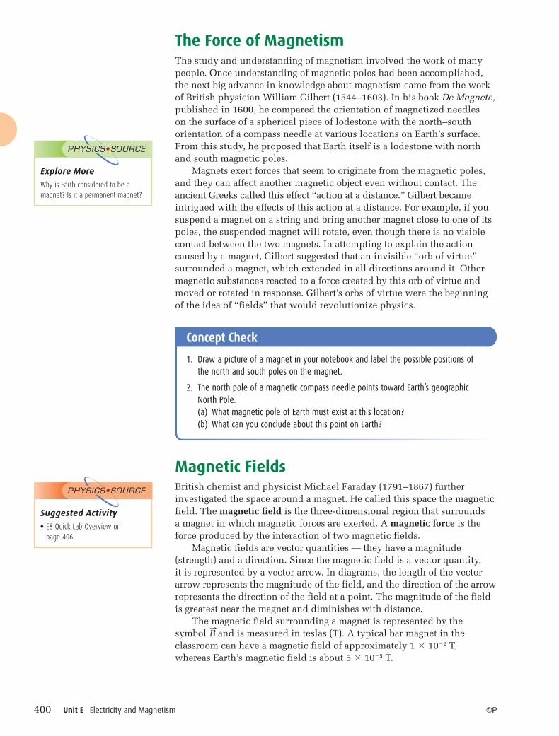
Maricourt determined that lodestone had two poles. In fact, all magnets have a north pole (N pole) and a south pole (S pole). When the N pole of one magnet is brought toward the S pole of another magnet, the two magnets attract each other. When the N pole of one magnet is brought toward the N pole of another magnet, the two magnets repel each other. Two magnets also repel each other if the two S poles are brought together. These observations led to the law of magnetism (Figure 12.3). This law states:
Like magnetic poles repel and unlike poles attract each other.
Section Summary
● The law of magnetism states that like magnetic poles repel each other and unlike poles attract each other.
● A magnetic field is the three-dimensional region around a magnet in which magnetic forces are exerted
● Oersted’s principle states that when a current moves through a conductor, it creates a magnetic field.
12.1
Figure 12.2 A piece of lodestone attracts small pieces of iron filings.
S N NS
S N SN
Figure 12.3 Two magnets can be used to show the law of magnetism. (a) Like magnetic poles repel and (b) unlike magnetic poles attract.
(a)
(b)
12-PHYSICS-11SE-Ch12.indd 39912-PHYSICS-11SE-Ch12.indd 399 7/26/10 10:04:18 AM7/26/10 10:04:18 AM
400 Unit E Electricity and Magnetism ©P
The Force of Magnetism The study and understanding of magnetism involved the work of many people. Once understanding of magnetic poles had been accomplished, the next big advance in knowledge about magnetism came from the work of British physician William Gilbert (1544–1603). In his book De Magnete, published in 1600, he compared the orientation of magnetized needles on the surface of a spherical piece of lodestone with the north–south orientation of a compass needle at various locations on Earth’s surface. From this study, he proposed that Earth itself is a lodestone with north and south magnetic poles.
Magnets exert forces that seem to originate from the magnetic poles, and they can affect another magnetic object even without contact. The ancient Greeks called this effect “action at a distance.” Gilbert became intrigued with the effects of this action at a distance. For example, if you suspend a magnet on a string and bring another magnet close to one of its poles, the suspended magnet will rotate, even though there is no visible contact between the two magnets. In attempting to explain the action caused by a magnet, Gilbert suggested that an invisible “orb of virtue” surrounded a magnet, which extended in all directions around it. Other magnetic substances reacted to a force created by this orb of virtue and moved or rotated in response. Gilbert’s orbs of virtue were the beginning of the idea of “fields” that would revolutionize physics.
Magnetic FieldsBritish chemist and physicist Michael Faraday (1791–1867) further investigated the space around a magnet. He called this space the magnetic field. The magnetic field is the three-dimensional region that surrounds a magnet in which magnetic forces are exerted. A magnetic force is the force produced by the interaction of two magnetic fields.
Magnetic fields are vector quantities — they have a magnitude (strength) and a direction. Since the magnetic field is a vector quantity, it is represented by a vector arrow. In diagrams, the length of the vector arrow represents the magnitude of the field, and the direction of the arrow represents the direction of the field at a point. The magnitude of the field is greatest near the magnet and diminishes with distance.
The magnetic field surrounding a magnet is represented by the symbol � B and is measured in teslas (T). A typical bar magnet in the classroom can have a magnetic field of approximately 1 � 10�2 T, whereas Earth’s magnetic field is about 5 � 10�5 T.
Concept Check
1. Draw a picture of a magnet in your notebook and label the possible positions of the north and south poles on the magnet.
2. The north pole of a magnetic compass needle points toward Earth’s geographic North Pole.(a) What magnetic pole of Earth must exist at this location?(b) What can you conclude about this point on Earth?
Explore More
Why is Earth considered to be a magnet? Is it a permanent magnet?
PHYSICS•SOURCE
Suggested Activity● E8 Quick Lab Overview on
page 406
PHYSICS•SOURCE
12-PHYSICS-11SE-Ch12.indd 40012-PHYSICS-11SE-Ch12.indd 400 7/26/10 10:04:19 AM7/26/10 10:04:19 AM
Chapter 12 Properties of magnetic fields apply in nature and technology. 401©P
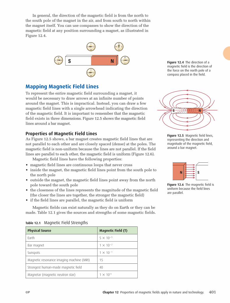
In general, the direction of the magnetic field is from the north to the south pole of the magnet in the air, and from south to north within the magnet itself. You can use compasses to show the direction of the magnetic field at any position surrounding a magnet, as illustrated in Figure 12.4.
Mapping Magnetic Field LinesTo represent the entire magnetic field surrounding a magnet, it would be necessary to draw arrows at an infinite number of points around the magnet. This is impractical. Instead, you can draw a few magnetic field lines with a single arrowhead indicating the direction of the magnetic field. It is important to remember that the magnetic field exists in three dimensions. Figure 12.5 shows the magnetic field lines around a bar magnet.
Properties of Magnetic Field LinesAs Figure 12.5 shows, a bar magnet creates magnetic field lines that are not parallel to each other and are closely spaced (dense) at the poles. The magnetic field is non-uniform because the lines are not parallel. If the field lines are parallel to each other, the magnetic field is uniform (Figure 12.6).
Magnetic field lines have the following properties:
• magnetic fi eld lines are continuous loops that never cross• inside the magnet, the magnetic fi eld lines point from the south pole to
the north pole• outside the magnet, the magnetic fi eld lines point away from the north
pole toward the south pole• the closeness of the lines represents the magnitude of the magnetic fi eld
(the closer the lines are together, the stronger the magnetic fi eld)• if the fi eld lines are parallel, the magnetic fi eld is uniform
Magnetic fields can exist naturally as they do on Earth or they can be made. Table 12.1 gives the sources and strengths of some magnetic fields.
S N
N
EW
S
N
E
W
S
N
E
W
S
E
W
NS
E
W
NS
S N
Figure 12.5 Magnetic field lines, representing the direction and magnitude of the magnetic field, around a bar magnet.
Figure 12.4 The direction of a magnetic field is the direction of the force on the north pole of a compass placed in the field.
N S
Figure 12.6 The magnetic field is uniform because the field lines are parallel.
Physical Source Magnetic Field (T)
Earth 5 � 10�5
Bar magnet 1 � 10�2
Sunspots 1 � 10�1
Magnetic resonance imaging machine (MRI) 15
Strongest human-made magnetic field 40
Magnetar (magnetic neutron star) 1 � 1011
Table 12.1 Magnetic Field Strengths
12-PHYSICS-11SE-Ch12.indd 40112-PHYSICS-11SE-Ch12.indd 401 7/26/10 10:04:19 AM7/26/10 10:04:19 AM
402 Unit E Electricity and Magnetism ©P
Domain Theory and MagnetizationA material that is made from a magnetized material and creates a magnetic field is a permanent magnet. Some materials become magnetized when they are placed in an external magnetic field. These are called ferromagnetic materials, and include iron, nickel, and cobalt. The outermost electrons of the atoms of ferromagnetic materials create tiny magnetic fields in each atom. The magnetic fields of adjacent atoms can align to reinforce each other, forming small regions, or domains, with intense magnetic fields. Domains generally range from 0.001 mm to 1 mm across, and may contain billions of atoms.
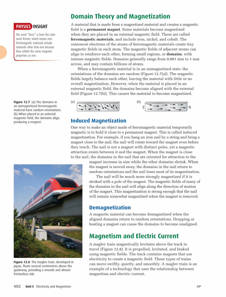
When a ferromagnetic material is in an unmagnetized state, the orientations of the domains are random (Figure 12.7(a)). The magnetic fields largely balance each other, leaving the material with little or no overall magnetization. However, when the material is placed in an external magnetic field, the domains become aligned with the external field (Figure 12.7(b)). This causes the material to become magnetized.
Induced MagnetizationOne way to make an object made of ferromagnetic material temporarily magnetic is to hold it close to a permanent magnet. This is called induced magnetization. For example, if you hang an iron nail by a string and bring a magnet close to the nail, the nail will rotate toward the magnet even before they touch. The nail is not a magnet with distinct poles, yet a magnetic attraction exists between it and the magnet. When the magnet is close to the nail, the domains in the nail that are oriented for attraction to the
magnet increase in size while the other domains shrink. When the magnet is moved away, the domains in the nail return to random orientations and the nail loses most of its magnetization.
The nail will be much more strongly magnetized if it is stroked with a pole of the magnet. The magnetic fields of many of the domains in the nail will align along the direction of motion of the magnet. This magnetization is strong enough that the nail will remain somewhat magnetized when the magnet is removed.
DemagnetizationA magnetic material can become demagnetized when the aligned domains return to random orientations. Dropping or heating a magnet can cause the domains to become unaligned.
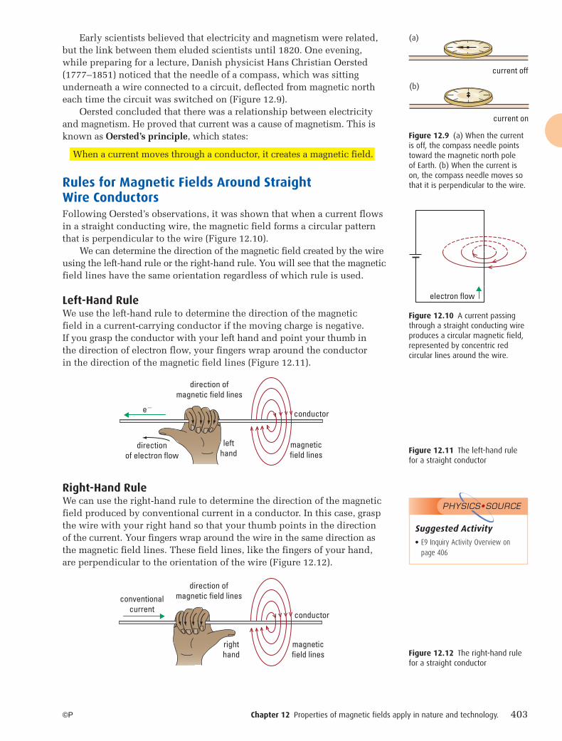
Magnetism and Electric CurrentA maglev train magnetically levitates above the track to travel (Figure 12.8). It is propelled, levitated, and braked using magnetic fields. The track contains magnets that use electricity to create a magnetic field. These types of trains can move swiftly, quietly, and smoothly. A maglev train is an example of a technology that uses the relationship between magnetism and electric current.
S N
Figure 12.7 (a) The domains in an unmagnetized ferromagnetic material have random orientations. (b) When placed in an external magnetic field, the domains align, producing a magnet.
(a)
Figure 12.8 The maglev train, developed in Japan, floats several centimetres above the guideway, providing a smooth and almost frictionless ride.
(b)
PHYSICS INSIGHT
The word “ferro” is from the Latin word ferrum, which means iron. Ferromagnetic materials include materials other than iron because they exhibit the same magnetic properties as iron.
12-PHYSICS-11SE-Ch12.indd 40212-PHYSICS-11SE-Ch12.indd 402 7/26/10 10:04:20 AM7/26/10 10:04:20 AM
Chapter 12 Properties of magnetic fields apply in nature and technology. 403©P
Early scientists believed that electricity and magnetism were related, but the link between them eluded scientists until 1820. One evening, while preparing for a lecture, Danish physicist Hans Christian Oersted (1777–1851) noticed that the needle of a compass, which was sitting underneath a wire connected to a circuit, deflected from magnetic north each time the circuit was switched on (Figure 12.9).
Oersted concluded that there was a relationship between electricity and magnetism. He proved that current was a cause of magnetism. This is known as Oersted’s principle, which states:
When a current moves through a conductor, it creates a magnetic field.
Rules for Magnetic Fields Around Straight Wire ConductorsFollowing Oersted’s observations, it was shown that when a current flows in a straight conducting wire, the magnetic field forms a circular pattern that is perpendicular to the wire (Figure 12.10).
We can determine the direction of the magnetic field created by the wire using the left-hand rule or the right-hand rule. You will see that the magnetic field lines have the same orientation regardless of which rule is used.
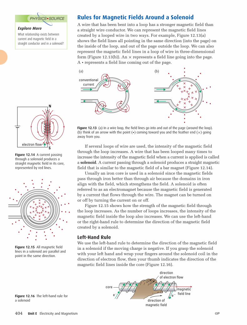
Left-Hand RuleWe use the left-hand rule to determine the direction of the magnetic field in a current-carrying conductor if the moving charge is negative. If you grasp the conductor with your left hand and point your thumb in the direction of electron flow, your fingers wrap around the conductor in the direction of the magnetic field lines (Figure 12.11).
Right-Hand RuleWe can use the right-hand rule to determine the direction of the magnetic field produced by conventional current in a conductor. In this case, grasp the wire with your right hand so that your thumb points in the direction of the current. Your fingers wrap around the wire in the same direction as the magnetic field lines. These field lines, like the fingers of your hand, are perpendicular to the orientation of the wire (Figure 12.12).
Figure 12.9 (a) When the current is off, the compass needle points toward the magnetic north pole of Earth. (b) When the current is on, the compass needle moves so that it is perpendicular to the wire.
current off
current on
(a)
(b)
electron flow
Figure 12.10 A current passing through a straight conducting wire produces a circular magnetic field, represented by concentric red circular lines around the wire.
directionof electron flow
conductor
magneticfield lines
direction ofmagnetic field lines
lefthand
e�
Figure 12.11 The left-hand rule for a straight conductor
conductor
magneticfield lines
direction ofmagnetic field linesconventional
current
righthand Figure 12.12 The right-hand rule
for a straight conductor
Suggested Activity● E9 Inquiry Activity Overview on
page 406
PHYSICS•SOURCE
12-PHYSICS-11SE-Ch12.indd 40312-PHYSICS-11SE-Ch12.indd 403 7/26/10 10:04:24 AM7/26/10 10:04:24 AM
404 Unit E Electricity and Magnetism ©P
Rules for Magnetic Fields Around a SolenoidA wire that has been bent into a loop has a stronger magnetic field than a straight wire conductor. We can represent the magnetic field lines created by a looped wire in two ways. For example, Figure 12.13(a) shows the field lines all pointing in the same direction (into the page) on the inside of the loop, and out of the page outside the loop. We can also represent the magnetic field lines in a loop of wire in three-dimensional form (Figure 12.13(b)). An × represents a field line going into the page. A • represents a field line coming out of the page.
If several loops of wire are used, the intensity of the magnetic field through the loop increases. A wire that has been looped many times to increase the intensity of the magnetic field when a current is applied is called a solenoid. A current passing through a solenoid produces a straight magnetic field that is similar to the magnetic field of a bar magnet (Figure 12.14).
Usually an iron core is used in a solenoid since the magnetic fields pass through iron better than through air because the domains in iron align with the field, which strengthens the field. A solenoid is often referred to as an electromagnet because the magnetic field is generated by a current that flows through the wire. The magnet can be turned on or off by turning the current on or off.
Figure 12.15 shows how the strength of the magnetic field through the loop increases. As the number of loops increases, the intensity of the magnetic field inside the loop also increases. We can use the left-hand or the right-hand rule to determine the direction of the magnetic field created by a solenoid.
Left-Hand RuleWe use the left-hand rule to determine the direction of the magnetic field in a solenoid if the moving charge is negative. If you grasp the solenoid with your left hand and wrap your fingers around the solenoid coil in the direction of electron flow, then your thumb indicates the direction of the magnetic field lines inside the core (Figure 12.16).
Figure 12.13 (a) In a wire loop, the field lines go into and out of the page (around the loop). (b) Think of an arrow with the point (•) coming toward you and the feather end (×) going away from you.
conventionalcurrent
(a) (b)
N
Selectron flow
Figure 12.14 A current passing through a solenoid produces a straight magnetic field in its core, represented by red lines.
directionof electron flow
magneticfield line
direction ofmagnetic field
e� e�
core
Figure 12.16 The left-hand rule for a solenoid
Figure 12.15 All magnetic field lines in a solenoid are parallel and point in the same direction.
Explore More
What relationship exists between current and magnetic field in a straight conductor and in a solenoid?
PHYSICS•SOURCE
12-PHYSICS-11SE-Ch12.indd 40412-PHYSICS-11SE-Ch12.indd 404 7/26/10 10:04:24 AM7/26/10 10:04:24 AM
Chapter 12 Properties of magnetic fields apply in nature and technology. 405©P
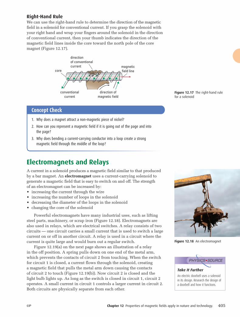
Right-Hand RuleWe can use the right-hand rule to determine the direction of the magnetic field in a solenoid for conventional current. If you grasp the solenoid with your right hand and wrap your fingers around the solenoid in the direction of conventional current, then your thumb indicates the direction of the magnetic field lines inside the core toward the north pole of the core magnet (Figure 12.17).
Electromagnets and RelaysA current in a solenoid produces a magnetic field similar to that produced by a bar magnet. An electromagnet uses a current-carrying solenoid to generate a magnetic field that is easy to switch on and off. The strength of an electromagnet can be increased by:• increasing the current through the wire• increasing the number of loops in the solenoid• decreasing the diameter of the loops in the solenoid• changing the core of the solenoid
Powerful electromagnets have many industrial uses, such as lifting steel parts, machinery, or scrap iron (Figure 12.18). Electromagnets are also used in relays, which are electrical switches. A relay consists of two circuits — one circuit carries a small current that is used to switch a large current on or off in another circuit. A relay is used in a circuit where the current is quite large and would burn out a regular switch.
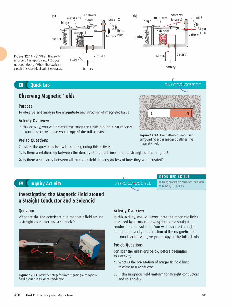
Figure 12.19(a) on the next page shows an illustration of a relay in the off position. A spring pulls down on one end of the metal arm, which prevents the contacts of circuit 2 from touching. When the switch for circuit 1 is closed, a current flows through the solenoid, creating a magnetic field that pulls the metal arm down causing the contacts of circuit 2 to touch (Figure 12.19(b)). Now circuit 2 is closed and the light bulb lights up. As long as the switch is closed in circuit 1, circuit 2 operates. A small current in circuit 1 controls a larger current in circuit 2. Both circuits are physically separate from each other.
conventionalcurrent
magneticfield linecore
direction ofmagnetic field
directionof conventionalcurrent
Figure 12.17 The right-hand rule for a solenoid
Figure 12.18 An electromagnet
Concept Check
1. Why does a magnet attract a non-magnetic piece of nickel?
2. How can you represent a magnetic field if it is going out of the page and into the page?
3. Why does bending a current-carrying conductor into a loop create a strong magnetic field through the middle of the loop?
Take It Further
An electric doorbell uses a solenoid in its design. Research the design of a doorbell and how it functions.
PHYSICS•SOURCE
12-PHYSICS-11SE-Ch12.indd 40512-PHYSICS-11SE-Ch12.indd 405 7/26/10 10:04:24 AM7/26/10 10:04:24 AM
406 Unit E Electricity and Magnetism ©P
PurposeTo observe and analyze the magnitude and direction of magnetic fields
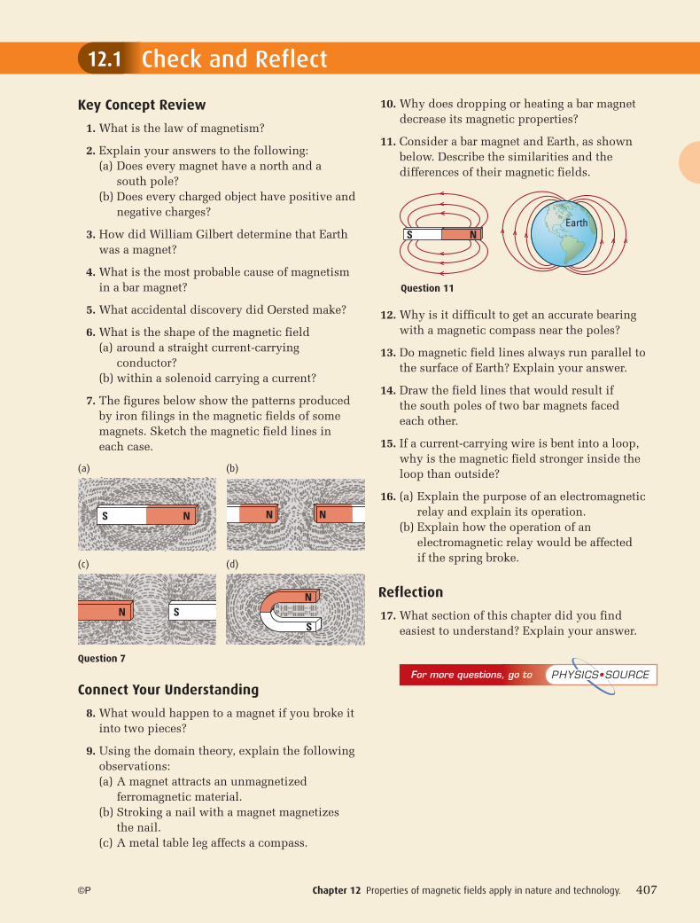
Activity OverviewIn this activity, you will observe the magnetic fields around a bar magnet.
Your teacher will give you a copy of the full activity.
Prelab QuestionsConsider the questions below before beginning this activity.
1. Is there a relationship between the density of the fi eld lines and the strength of the magnet?
2. Is there a similarity between all magnetic fi eld lines regardless of how they were created?
Observing Magnetic Fields
E8 Quick Lab PHYSICS•SOURCE
S N
Figure 12.20 The pattern of iron filings surrounding a bar magnet outlines the magnetic field.
QuestionWhat are the characteristics of a magnetic field around a straight conductor and a solenoid?
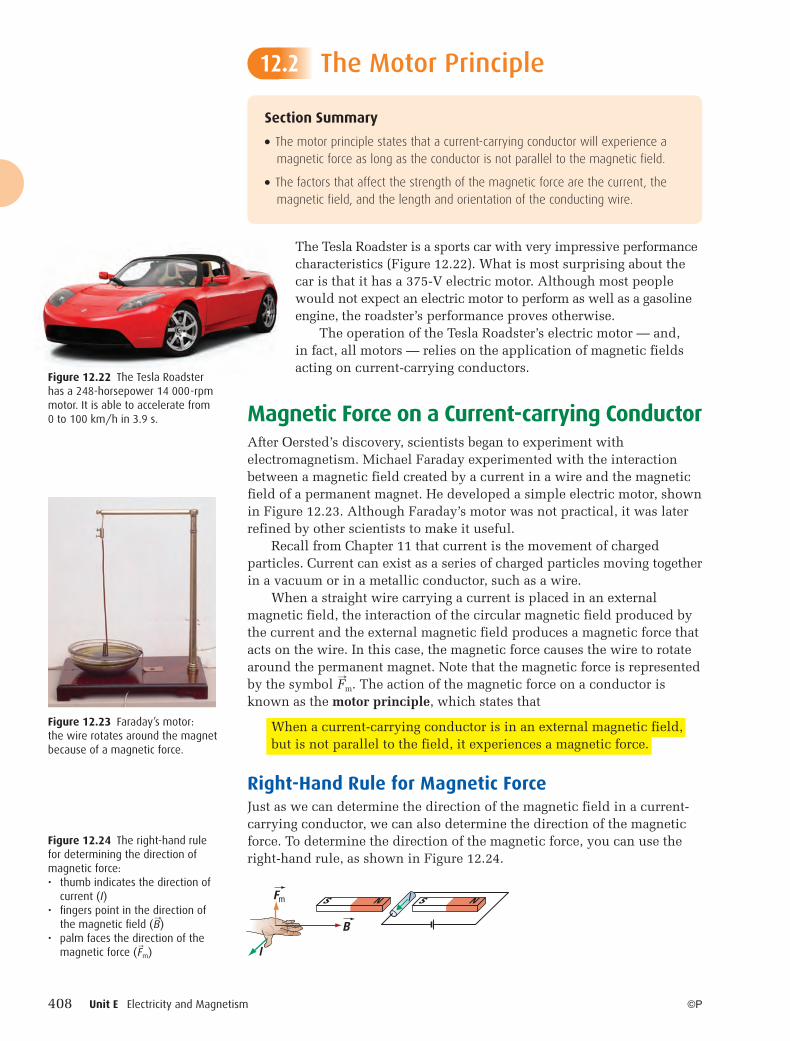
Activity OverviewIn this activity, you will investigate the magnetic fields produced by a current flowing through a straight conductor and a solenoid. You will also use the right-hand rule to verify the direction of the magnetic field.
Your teacher will give you a copy of the full activity.
Prelab QuestionsConsider the questions below before beginning this activity.
1. What is the orientation of magnetic fi eld lines relative to a conductor?
2. Is the magnetic fi eld uniform for straight conductors and solenoids?
Investigating the Magnetic Field around a Straight Conductor and a Solenoid
Inquiry Activity PHYSICS•SOURCE
REQUIRED SKILLS■ Using appropriate equipment and tools■ Drawing conclusions
E9
Figure 12.21 Activity setup for investigating a magnetic field around a straight conductor.
hingemetal arm
lightbulb
circuit 2
circuit 1
contacts(open)
springbattery
battery
switch
solenoid
hingemetal arm
lightbulb
circuit 2
circuit 1
contacts(closed)
springbattery
battery
switch
solenoid
Figure 12.19 (a) When the switch in circuit 1 is open, circuit 2 does not operate. (b) When the switch in circuit 1 is closed, circuit 2 operates.
(a) (b)
12-PHYSICS-11SE-Ch12.indd 40612-PHYSICS-11SE-Ch12.indd 406 7/26/10 10:04:25 AM7/26/10 10:04:25 AM
Chapter 12 Properties of magnetic fields apply in nature and technology. 407
Check and Reflect
©P
Key Concept Review
1. What is the law of magnetism?
2. Explain your answers to the following: (a) Does every magnet have a north and a
south pole? (b) Does every charged object have positive and
negative charges?
3. How did William Gilbert determine that Earth was a magnet?
4. What is the most probable cause of magnetism in a bar magnet?
5. What accidental discovery did Oersted make?
6. What is the shape of the magnetic field (a) around a straight current-carrying
conductor? (b) within a solenoid carrying a current?
7. The figures below show the patterns produced by iron filings in the magnetic fields of some magnets. Sketch the magnetic field lines in each case.
Connect Your Understanding
8. What would happen to a magnet if you broke it into two pieces?
9. Using the domain theory, explain the following observations:
(a) A magnet attracts an unmagnetized ferromagnetic material.
(b) Stroking a nail with a magnet magnetizes the nail.
(c) A metal table leg affects a compass.
10. Why does dropping or heating a bar magnet decrease its magnetic properties?
11. Consider a bar magnet and Earth, as shown below. Describe the similarities and the differences of their magnetic fields.
12. Why is it difficult to get an accurate bearing with a magnetic compass near the poles?
13. Do magnetic field lines always run parallel to the surface of Earth? Explain your answer.
14. Draw the field lines that would result if the south poles of two bar magnets faced each other.
15. If a current-carrying wire is bent into a loop, why is the magnetic field stronger inside the loop than outside?
16. (a) Explain the purpose of an electromagnetic relay and explain its operation.
(b) Explain how the operation of an electromagnetic relay would be affected if the spring broke.
Reflection
17. What section of this chapter did you find easiest to understand? Explain your answer.
12.1
S NEarth
Question 11
Question 7
(c)
SNN
S
S N N N
(a)
(d)
(b)
For more questions, go to PHYSICS•SOURCE
12-PHYSICS-11SE-Ch12.indd 40712-PHYSICS-11SE-Ch12.indd 407 7/26/10 10:04:27 AM7/26/10 10:04:27 AM
408 Unit E Electricity and Magnetism ©P
The Motor Principle
The Tesla Roadster is a sports car with very impressive performance characteristics (Figure 12.22). What is most surprising about the car is that it has a 375-V electric motor. Although most people would not expect an electric motor to perform as well as a gasoline engine, the roadster’s performance proves otherwise.
The operation of the Tesla Roadster’s electric motor — and, in fact, all motors — relies on the application of magnetic fields acting on current-carrying conductors.
Magnetic Force on a Current-carrying ConductorAfter Oersted’s discovery, scientists began to experiment with electromagnetism. Michael Faraday experimented with the interaction between a magnetic field created by a current in a wire and the magnetic field of a permanent magnet. He developed a simple electric motor, shown in Figure 12.23. Although Faraday’s motor was not practical, it was later refined by other scientists to make it useful.
Recall from Chapter 11 that current is the movement of charged particles. Current can exist as a series of charged particles moving together in a vacuum or in a metallic conductor, such as a wire.
When a straight wire carrying a current is placed in an external magnetic field, the interaction of the circular magnetic field produced by the current and the external magnetic field produces a magnetic force that acts on the wire. In this case, the magnetic force causes the wire to rotate around the permanent magnet. Note that the magnetic force is represented by the symbol � F m. The action of the magnetic force on a conductor is known as the motor principle, which states that
When a current-carrying conductor is in an external magnetic field, but is not parallel to the field, it experiences a magnetic force.
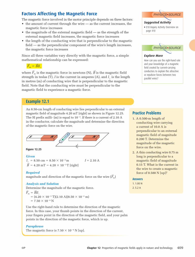
Right-Hand Rule for Magnetic ForceJust as we can determine the direction of the magnetic field in a current-carrying conductor, we can also determine the direction of the magnetic force. To determine the direction of the magnetic force, you can use the right-hand rule, as shown in Figure 12.24.
Section Summary
● The motor principle states that a current-carrying conductor will experience a magnetic force as long as the conductor is not parallel to the magnetic field.
● The factors that affect the strength of the magnetic force are the current, the magnetic field, and the length and orientation of the conducting wire.
12.2
Figure 12.23 Faraday’s motor: the wire rotates around the magnet because of a magnetic force.
Figure 12.22 The Tesla Roadster has a 248-horsepower 14 000-rpm motor. It is able to accelerate from 0 to 100 km/h in 3.9 s.
Figure 12.24 The right-hand rule for determining the direction of magnetic force:• thumb indicates the direction of
current (I)• fi ngers point in the direction of
the magnetic fi eld ( � B )• palm faces the direction of the
magnetic force ( � F m)
Fm
B
l
S N S Nl
12-PHYSICS-11SE-Ch12.indd 40812-PHYSICS-11SE-Ch12.indd 408 7/26/10 10:04:27 AM7/26/10 10:04:27 AM
Chapter 12 Properties of magnetic fields apply in nature and technology. 409©P
Factors Affecting the Magnetic ForceThe magnetic force involved in the motor principle depends on three factors:• the amount of current through the wire — as the current increases, the
magnetic force increases• the magnitude of the external magnetic fi eld — as the strength of the
external magnetic fi eld increases, the magnetic force increases• the length of the conducting wire that is perpendicular to the magnetic
fi eld — as the perpendicular component of the wire’s length increases, the magnetic force increases
Since all three variables vary directly with the magnetic force, a simple mathematical relationship can be expressed:
� F m � � B Il�
where � F m is the magnetic force in newtons (N), � B is the magnetic field strength in teslas (T), I is the current in amperes (A), and l� is the length in metres (m) of conducting wire that is perpendicular to the magnetic field. Note that the conducting wire must be perpendicular to the magnetic field to experience a magnetic force.
Example 12.1
An 8.50-cm length of conducting wire lies perpendicular to an external magnetic field of magnitude 4.20 mT [right] as shown in Figure 12.25. The SI prefix milli- (m) is equal to 10�3. If there is a current of 2.10 A in the conductor, calculate the magnitude and determine the direction of the magnetic force on the wire.
Given l� � 8.50 cm � 8.50 � 10�2 m I � 2.10 A
� B � 4.20 mT � 4.20 � 10�3 T [right]
Requiredmagnitude and direction of the magnetic force on the wire ( � F m)
Analysis and SolutionDetermine the magnitude of the magnetic force.
� F m � � B Il�
� (4.20 � 10�3 T)(2.10 A)(8.50 � 10�2 m) � 7.50 � 10�4 N
Use the right-hand rule to determine the direction of the magnetic force. In this case, your thumb points in the direction of the current, your fingers point in the direction of the magnetic field, and your palm points in the direction of the magnetic force, which is up.
ParaphraseThe magnetic force is 7.50 � 10�4 N [up].
S N S Nl
Figure 12.25
Practice Problems1. A 0.500-m length of
conducting wire carrying a current of 10.0 A is perpendicular to an external magnetic field of magnitude 0.200 T. Determine the magnitude of the magnetic force on the wire.
2. A thin conducting wire 0.75 m long is perpendicular to a magnetic field of magnitude 0.15 T. What is the current in the wire to create a magnetic force of 0.588 N [up]?
Answers1. 1.00 N
2. 5.2 A
Suggested Activity● E10 Inquiry Activity Overview on
page 410
PHYSICS•SOURCE
Explore More
How can you use the right-hand rule and your knowledge of a magnetic field created by current-carrying conductors to explain the attractive or repulsive forces between two parallel wires?
PHYSICS•SOURCE
12-PHYSICS-11SE-Ch12.indd 40912-PHYSICS-11SE-Ch12.indd 409 7/26/10 10:04:30 AM7/26/10 10:04:30 AM
410 Unit E Electricity and Magnetism ©P
Take It Further
Devices, such as an ammeter and a maglev train, are designed to usethe motor principle. Research the design of one of these devices and explain how the device uses the motor principle to operate.
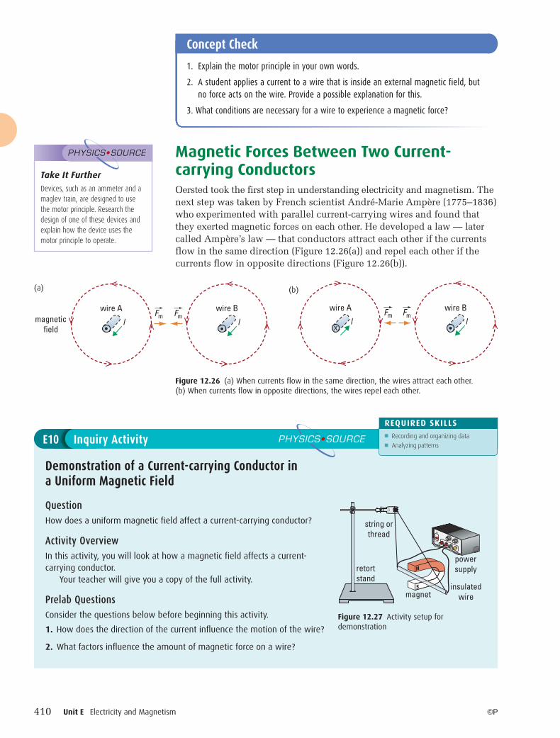
PHYSICS•SOURCE Magnetic Forces Between Two Current-carrying ConductorsOersted took the first step in understanding electricity and magnetism. The next step was taken by French scientist André-Marie Ampère (1775–1836) who experimented with parallel current-carrying wires and found that they exerted magnetic forces on each other. He developed a law — later called Ampère’s law — that conductors attract each other if the currents flow in the same direction (Figure 12.26(a)) and repel each other if the currents flow in opposite directions (Figure 12.26(b)).
Concept Check
1. Explain the motor principle in your own words.
2. A student applies a current to a wire that is inside an external magnetic field, but no force acts on the wire. Provide a possible explanation for this.
3. What conditions are necessary for a wire to experience a magnetic force?
Figure 12.26 (a) When currents flow in the same direction, the wires attract each other. (b) When currents flow in opposite directions, the wires repel each other.
magneticfield
wire A
l lFm Fm
wire B
xll
wire A wire BFm Fm
(a) (b)
QuestionHow does a uniform magnetic field affect a current-carrying conductor?
Activity OverviewIn this activity, you will look at how a magnetic field affects a current-carrying conductor.
Your teacher will give you a copy of the full activity.
Prelab QuestionsConsider the questions below before beginning this activity.
1. How does the direction of the current infl uence the motion of the wire?
2. What factors infl uence the amount of magnetic force on a wire?
Demonstration of a Current-carrying Conductor in a Uniform Magnetic Field
Inquiry Activity PHYSICS•SOURCE
REQUIRED SKILLS■ Recording and organizing data■ Analyzing patterns
E10
ON
OFF
powersupply
insulatedwiremagnet
string orthread
retortstand
N
S
Figure 12.27 Activity setup for demonstration
12-PHYSICS-11SE-Ch12.indd 41012-PHYSICS-11SE-Ch12.indd 410 7/26/10 10:04:30 AM7/26/10 10:04:30 AM
Chapter 12 Properties of magnetic fields apply in nature and technology. 411
Check and Reflect
©P
12.2
For more questions, go to PHYSICS•SOURCE
Key Concept Review
1. What factors affect the magnetic force on a conducting wire in an external magnetic field?
2. Explain the motor principle and the factors that influence it.
3. A current-carrying conductor is placed on a tabletop near a permanent magnet as shown below. Determine the resulting motion of the wire.
4. Draw a diagram that shows three wires running parallel to each other. The wires carry equal current in the same direction. Determine the net force on the middle wire.
5. A current-carrying wire is oriented perpendicular to an external magnetic field. Explain what happens to the magnetic force that the wire experiences as the wire slowly rotates until it is parallel to the field.
Connect Your Understanding
6. Will any of the wires shown in each of the following diagrams experience a magnetic force? Explain your answers.
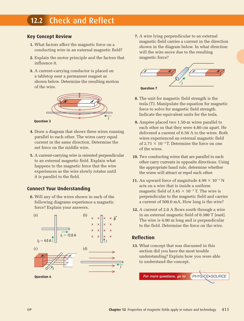
7. A wire lying perpendicular to an external magnetic field carries a current in the direction shown in the diagram below. In what direction will the wire move due to the resulting magnetic force?
8. The unit for magnetic field strength is the tesla (T). Manipulate the equation for magnetic force to solve for magnetic field strength. Indicate the equivalent units for the tesla.
9. Ampère placed two 1.50-m wires parallel to each other so that they were 4.80 cm apart. He delivered a current of 6.50 A to the wires. Both wires experienced an external magnetic field of 2.71 � 10�5 T. Determine the force on one of the wires.
10. Two conducting wires that are parallel to each other carry currents in opposite directions. Using the appropriate hand rule, determine whether the wires will attract or repel each other.
11. An upward force of magnitude 4.99 � 10�3 Nacts on a wire that is inside a uniform magnetic field of 3.45 � 10�3 T. The wire is perpendicular to the magnetic field and carries a current of 500.0 mA. How long is the wire?
12. A current of 2.0 A flows south through a wire in an external magnetic field of 0.380 T [east]. The wire is 4.00 m long and is perpendicular to the field. Determine the force on the wire.
Reflection
13. What concept that was discussed in this section did you have the most trouble understanding? Explain how you were able to understand the concept.
I
N S
Question 3
Question 6
N S
I1 � 12.0 A I2 � 4.0 A I
II
B(a) (b)
(c) (d)
I
S N S N
Question 7
12-PHYSICS-11SE-Ch12.indd 41112-PHYSICS-11SE-Ch12.indd 411 7/26/10 10:04:31 AM7/26/10 10:04:31 AM
412 Unit E Electricity and Magnetism ©P
S
Fm
cross-sectionof segment AB
cross-sectionof segment CD
FmB
B
B
C
D
AN
armature
brush
power source
��
Fm
S
commutator
I
I
Fm
stator
N
Using Electromagnetism
The motor principle states that a force acts on a current-carrying conductor in an external magnetic field. The development of electric motors is a direct application of the motor principle. The motor principle is also involved in the operation of many other devices including the loudspeaker and particle accelerators.
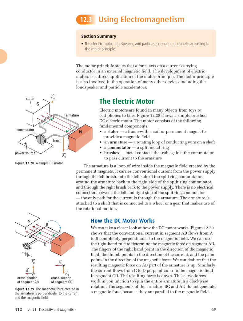
The Electric MotorElectric motors are found in many objects from toys to cell phones to fans. Figure 12.28 shows a simple brushed DC electric motor. The motor consists of the following fundamental components: • a stator — a frame with a coil or permanent magnet to
provide a magnetic fi eld• an armature — a rotating loop of conducting wire on a shaft• a commutator — a split metal ring• brushes — metal contacts that rub against the commutator
to pass current to the armature
The armature is a loop of wire inside the magnetic field created by the permanent magnets. It carries conventional current from the power supply through the left brush, into the left side of the split ring commutator, around the armature back to the right side of the split ring commutator, and through the right brush back to the power supply. There is no electrical connection between the left and right side of the split ring commutator — the only path for the current is through the armature. The armature is attached to a shaft that is connected to a wheel or a gear that makes use of the rotational motion.
How the DC Motor Works We can take a closer look at how the DC motor works. Figure 12.29 shows that the conventional current in segment AB flows from A to B completely perpendicular to the magnetic field. We can use the right-hand rule to determine the magnetic force on segment AB. The fingers of the right hand point in the direction of the magnetic field, the thumb points in the direction of the current, and the palm points in the direction of the magnetic force. We can deduce that the resulting magnetic force on AB part of the armature is up. Similarly the current flows from C to D perpendicular to the magnetic field in segment CD. The resulting force is down. These two forces work in conjunction to spin the entire armature in a clockwise rotation. The segments of the armature BC and AD do not generate a magnetic force because they are parallel to the magnetic field.
Section Summary
● The electric motor, loudspeaker, and particle accelerator all operate according to the motor principle.
12.3
Figure 12.28 A simple DC motor
Figure 12.29 The magnetic force created in the armature is perpendicular to the current and the magnetic field.
12-PHYSICS-11SE-Ch12.indd 41212-PHYSICS-11SE-Ch12.indd 412 7/26/10 10:04:31 AM7/26/10 10:04:31 AM
Chapter 12 Properties of magnetic fields apply in nature and technology. 413©P
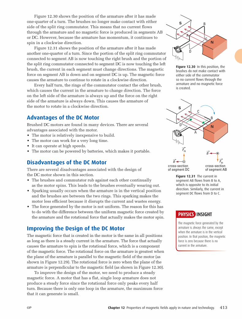
Figure 12.30 shows the position of the armature after it has made one-quarter of a turn. The brushes no longer make contact with either side of the split ring commutator. This means that no current flows through the armature and no magnetic force is produced in segments AB or DC. However, because the armature has momentum, it continues to spin in a clockwise direction.
Figure 12.31 shows the position of the armature after it has made another one-quarter of a turn. Since the portion of the split ring commutator connected to segment AB is now touching the right brush and the portion of the split ring commutator connected to segment DC is now touching the left brush, the current in each segment must change directions. The magnetic force on segment AB is down and on segment DC is up. The magnetic force causes the armature to continue to rotate in a clockwise direction.
Every half turn, the rings of the commutator contact the other brush, which causes the current in the armature to change direction. The force on the left side of the armature is always up and the force on the right side of the armature is always down. This causes the armature of the motor to rotate in a clockwise direction.
Advantages of the DC MotorBrushed DC motors are found in many devices. There are several advantages associated with the motor. • The motor is relatively inexpensive to build.• The motor can work for a very long time.• It can operate at high speeds.• The motor can be powered by batteries, which makes it portable.
Disadvantages of the DC MotorThere are several disadvantages associated with the design of the DC motor shown in this section. • The brushes and commutator rub against each other continually
as the motor spins. This leads to the brushes eventually wearing out. • Sparking usually occurs when the armature is in the vertical position
and the brushes are between the two rings. This sparking makes the motor less effi cient because it disrupts the current and wastes energy.
• The force generated by the motor is not uniform. The reason for this has to do with the difference between the uniform magnetic force created by the armature and the rotational force that actually makes the motor spin.
Improving the Design of the DC MotorThe magnetic force that is created in the motor is the same in all positions as long as there is a steady current in the armature. The force that actually causes the armature to spin is the rotational force, which is a component of the magnetic force. The rotational force on the armature is greatest when the plane of the armature is parallel to the magnetic field of the motor (as shown in Figure 12.29). The rotational force is zero when the plane of the armature is perpendicular to the magnetic field (as shown in Figure 12.30).
To improve the design of the motor, we need to produce a steady magnetic force. A motor that has a flat, single loop armature does not produce a steady force since the rotational force only peaks every half turn. Because there is only one loop in the armature, the maximum force that it can generate is small.
S B
D
CN
A
Figure 12.30 In this position, the brushes do not make contact with either side of the commutator so no current flows through the armature and no magnetic force is created.
S
Fm
cross-sectionof segment DC
cross-sectionof segment AB
FmB
B
C
B
A
DN
Figure 12.31 The current in segment AB flows from B to A, which is opposite to its initial direction. Similarly, the current in segment DC flows from D to C.
PHYSICS INSIGHT
The magnetic force generated by the armature is always the same, except when the armature is in the vertical position. In that position, the magnetic force is zero because there is no current in the armature.
12-PHYSICS-11SE-Ch12.indd 41312-PHYSICS-11SE-Ch12.indd 413 7/26/10 10:04:31 AM7/26/10 10:04:31 AM
414 Unit E Electricity and Magnetism ©P
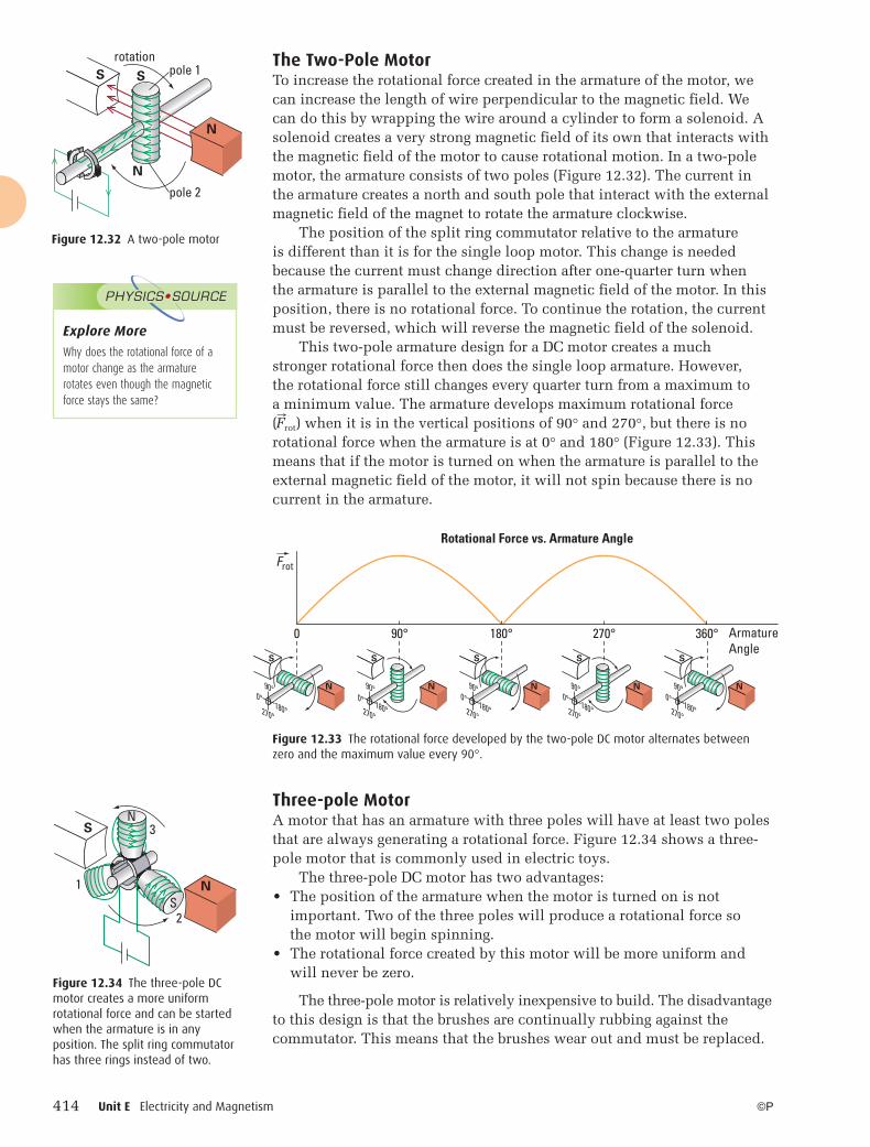
The Two-Pole MotorTo increase the rotational force created in the armature of the motor, we can increase the length of wire perpendicular to the magnetic field. We can do this by wrapping the wire around a cylinder to form a solenoid. A solenoid creates a very strong magnetic field of its own that interacts with the magnetic field of the motor to cause rotational motion. In a two-pole motor, the armature consists of two poles (Figure 12.32). The current in the armature creates a north and south pole that interact with the external magnetic field of the magnet to rotate the armature clockwise.
The position of the split ring commutator relative to the armature is different than it is for the single loop motor. This change is needed because the current must change direction after one-quarter turn when the armature is parallel to the external magnetic field of the motor. In this position, there is no rotational force. To continue the rotation, the current must be reversed, which will reverse the magnetic field of the solenoid.
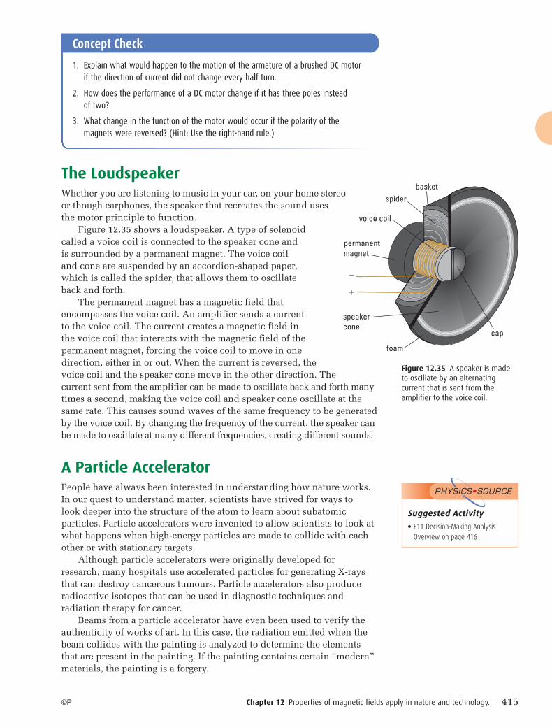
This two-pole armature design for a DC motor creates a much stronger rotational force then does the single loop armature. However, the rotational force still changes every quarter turn from a maximum to a minimum value. The armature develops maximum rotational force ( � F rot) when it is in the vertical positions of 90° and 270°, but there is no rotational force when the armature is at 0° and 180° (Figure 12.33). This means that if the motor is turned on when the armature is parallel to the external magnetic field of the motor, it will not spin because there is no current in the armature.
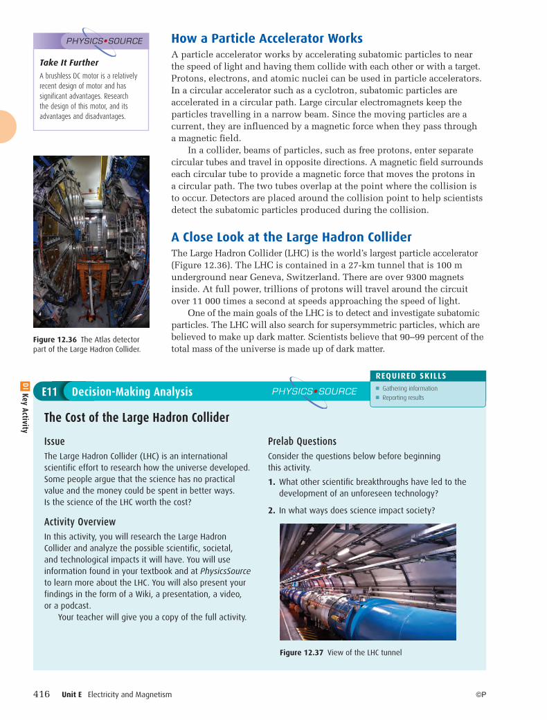
Three-pole MotorA motor that has an armature with three poles will have at least two poles that are always generating a rotational force. Figure 12.34 shows a three-pole motor that is commonly used in electric toys.
The three-pole DC motor has two advantages:• The position of the armature when the motor is turned on is not
important. Two of the three poles will produce a rotational force so the motor will begin spinning.
• The rotational force created by this motor will be more uniform and will never be zero.
The three-pole motor is relatively inexpensive to build. The disadvantage to this design is that the brushes are continually rubbing against the commutator. This means that the brushes wear out and must be replaced.
Rotational Force vs. Armature Angle
S
N
S
N
S
N
S
N
S
N
0 90° 180° 270° 360° ArmatureAngle
Frot
0°270°
90°
180°0°
270°
90°
180° 270°
90°0°
180° 180°270°
90°0°
180°0°
270°
90°
pole 1
pole 2
rotationS S
N
N
Figure 12.32 A two-pole motor
Figure 12.33 The rotational force developed by the two-pole DC motor alternates between zero and the maximum value every 90°.
Explore More
Why does the rotational force of a motor change as the armature rotates even though the magnetic force stays the same?
PHYSICS•SOURCE
1
2
3N
S
S
N
Figure 12.34 The three-pole DC motor creates a more uniform rotational force and can be started when the armature is in any position. The split ring commutator has three rings instead of two.
12-PHYSICS-11SE-Ch12.indd 41412-PHYSICS-11SE-Ch12.indd 414 7/26/10 10:04:31 AM7/26/10 10:04:31 AM
Chapter 12 Properties of magnetic fields apply in nature and technology. 415©P
permanentmagnet
spider
voice coil
basket
�
�
foam
cap
speakercone
Concept Check
1. Explain what would happen to the motion of the armature of a brushed DC motor if the direction of current did not change every half turn.
2. How does the performance of a DC motor change if it has three poles instead of two?
3. What change in the function of the motor would occur if the polarity of the magnets were reversed? (Hint: Use the right-hand rule.)
The LoudspeakerWhether you are listening to music in your car, on your home stereo or though earphones, the speaker that recreates the sound uses the motor principle to function.
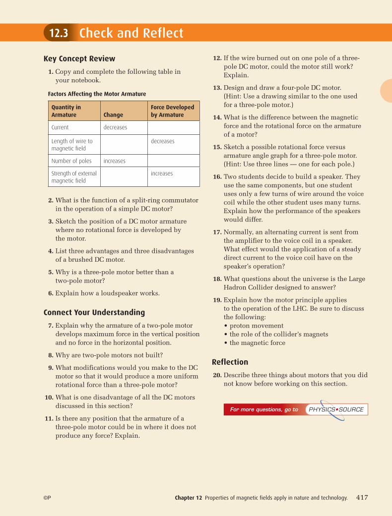
Figure 12.35 shows a loudspeaker. A type of solenoid called a voice coil is connected to the speaker cone and is surrounded by a permanent magnet. The voice coil and cone are suspended by an accordion-shaped paper, which is called the spider, that allows them to oscillate back and forth.
The permanent magnet has a magnetic field that encompasses the voice coil. An amplifier sends a current to the voice coil. The current creates a magnetic field in the voice coil that interacts with the magnetic field of the permanent magnet, forcing the voice coil to move in one direction, either in or out. When the current is reversed, the voice coil and the speaker cone move in the other direction. The current sent from the amplifier can be made to oscillate back and forth many times a second, making the voice coil and speaker cone oscillate at the same rate. This causes sound waves of the same frequency to be generated by the voice coil. By changing the frequency of the current, the speaker can be made to oscillate at many different frequencies, creating different sounds.
A Particle AcceleratorPeople have always been interested in understanding how nature works. In our quest to understand matter, scientists have strived for ways to look deeper into the structure of the atom to learn about subatomic particles. Particle accelerators were invented to allow scientists to look at what happens when high-energy particles are made to collide with each other or with stationary targets.
Although particle accelerators were originally developed for research, many hospitals use accelerated particles for generating X-rays that can destroy cancerous tumours. Particle accelerators also produce radioactive isotopes that can be used in diagnostic techniques and radiation therapy for cancer.
Beams from a particle accelerator have even been used to verify the authenticity of works of art. In this case, the radiation emitted when the beam collides with the painting is analyzed to determine the elements that are present in the painting. If the painting contains certain “modern” materials, the painting is a forgery.
Figure 12.35 A speaker is made to oscillate by an alternating current that is sent from the amplifier to the voice coil.
Suggested Activity● E11 Decision-Making Analysis
Overview on page 416
PHYSICS•SOURCE
12-PHYSICS-11SE-Ch12.indd 41512-PHYSICS-11SE-Ch12.indd 415 7/26/10 10:04:31 AM7/26/10 10:04:31 AM
416 Unit E Electricity and Magnetism ©P
How a Particle Accelerator WorksA particle accelerator works by accelerating subatomic particles to near the speed of light and having them collide with each other or with a target. Protons, electrons, and atomic nuclei can be used in particle accelerators. In a circular accelerator such as a cyclotron, subatomic particles are accelerated in a circular path. Large circular electromagnets keep the particles travelling in a narrow beam. Since the moving particles are a current, they are influenced by a magnetic force when they pass through a magnetic field.
In a collider, beams of particles, such as free protons, enter separate circular tubes and travel in opposite directions. A magnetic field surrounds each circular tube to provide a magnetic force that moves the protons in a circular path. The two tubes overlap at the point where the collision is to occur. Detectors are placed around the collision point to help scientists detect the subatomic particles produced during the collision.
A Close Look at the Large Hadron ColliderThe Large Hadron Collider (LHC) is the world’s largest particle accelerator (Figure 12.36). The LHC is contained in a 27-km tunnel that is 100 m underground near Geneva, Switzerland. There are over 9300 magnets inside. At full power, trillions of protons will travel around the circuit over 11 000 times a second at speeds approaching the speed of light.
One of the main goals of the LHC is to detect and investigate subatomic particles. The LHC will also search for supersymmetric particles, which are believed to make up dark matter. Scientists believe that 90–99 percent of the total mass of the universe is made up of dark matter.
IssueThe Large Hadron Collider (LHC) is an international scientific effort to research how the universe developed. Some people argue that the science has no practical value and the money could be spent in better ways. Is the science of the LHC worth the cost?
Activity OverviewIn this activity, you will research the Large Hadron Collider and analyze the possible scientific, societal, and technological impacts it will have. You will use information found in your textbook and at PhysicsSource to learn more about the LHC. You will also present your findings in the form of a Wiki, a presentation, a video, or a podcast.
Your teacher will give you a copy of the full activity.
Prelab QuestionsConsider the questions below before beginning this activity.
1. What other scientifi c breakthroughs have led to the development of an unforeseen technology?
2. In what ways does science impact society?
The Cost of the Large Hadron Collider
Decision-Making Analysis PHYSICS•SOURCE
REQUIRED SKILLS■ Gathering information■ Reporting results
E11
Figure 12.37 View of the LHC tunnel
Figure 12.36 The Atlas detector part of the Large Hadron Collider.
Take It Further
A brushless DC motor is a relatively recent design of motor and has significant advantages. Research the design of this motor, and its advantages and disadvantages.
PHYSICS•SOURCE
DI Key Activity
12-PHYSICS-11SE-Ch12.indd 41612-PHYSICS-11SE-Ch12.indd 416 7/26/10 10:04:31 AM7/26/10 10:04:31 AM
Chapter 12 Properties of magnetic fields apply in nature and technology. 417
Check and Reflect
©P
Key Concept Review
1. Copy and complete the following table in your notebook.
2. What is the function of a split-ring commutator in the operation of a simple DC motor?
3. Sketch the position of a DC motor armature where no rotational force is developed by the motor.
4. List three advantages and three disadvantages of a brushed DC motor.
5. Why is a three-pole motor better than a two-pole motor?
6. Explain how a loudspeaker works.
Connect Your Understanding
7. Explain why the armature of a two-pole motor develops maximum force in the vertical position and no force in the horizontal position.
8. Why are two-pole motors not built?
9. What modifications would you make to the DC motor so that it would produce a more uniform rotational force than a three-pole motor?
10. What is one disadvantage of all the DC motors discussed in this section?
11. Is there any position that the armature of a three-pole motor could be in where it does not produce any force? Explain.
12. If the wire burned out on one pole of a three-pole DC motor, could the motor still work? Explain.
13. Design and draw a four-pole DC motor. (Hint: Use a drawing similar to the one used for a three-pole motor.)
14. What is the difference between the magnetic force and the rotational force on the armature of a motor?
15. Sketch a possible rotational force versus armature angle graph for a three-pole motor. (Hint: Use three lines — one for each pole.)
16. Two students decide to build a speaker. They use the same components, but one student uses only a few turns of wire around the voice coil while the other student uses many turns. Explain how the performance of the speakers would differ.
17. Normally, an alternating current is sent from the amplifier to the voice coil in a speaker. What effect would the application of a steady direct current to the voice coil have on the speaker’s operation?
18. What questions about the universe is the Large Hadron Collider designed to answer?
19. Explain how the motor principle applies to the operation of the LHC. Be sure to discuss the following:• proton movement • the role of the collider’s magnets • the magnetic force
Reflection
20. Describe three things about motors that you did not know before working on this section.
12.3
Quantity in Armature Change
Force Developed by Armature
Current decreases
Length of wire to magnetic field
decreases
Number of poles increases
Strength of external magnetic field
increases
Factors Affecting the Motor Armature
For more questions, go to PHYSICS•SOURCE
12-PHYSICS-11SE-Ch12.indd 41712-PHYSICS-11SE-Ch12.indd 417 7/26/10 10:04:36 AM7/26/10 10:04:36 AM
418 Unit E Electricity and Magnetism
CHAPTER REVIEWC H A P T E R
©P
Key Concept Review
1. What is the law of magnetism? k
2. What did Gilbert refer to as the “orb of virtue,” and what led him to make this reference? k
3. Sketch a diagram of Earth with its magnetic field lines. Be sure to indicate the direction of the field lines. k
4. For a permanent magnet, indicate the direction of the field lines
(a) outside the magnet. k (b) inside the magnet. k
5. With respect to the north and south poles formed by a solenoid, what is the direction of the field lines inside a solenoid? k
6. Four magnets are arranged across from each other as shown below. Copy this figure into your notebook and draw in the field lines. k
Question 6
7. Which of the following diagrams represents a possible magnetic field arrangement? k
Question 7
8. The following diagrams represent a portion of a magnetic field. Indicate the possible cause of the field and whether the field is uniform or not. k
Question 8
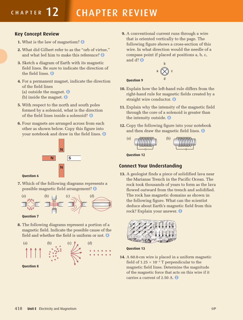
9. A conventional current runs through a wire that is oriented vertically to the page. The following figure shows a cross-section of this wire. In what direction would the needle of a compass point if placed at positions a, b, c, and d? k
Question 9
10. Explain how the left-hand rule differs from the right-hand rule for magnetic fields created by a straight wire conductor. k
11. Explain why the intensity of the magnetic field through the core of a solenoid is greater than the intensity outside. k
12. Copy the following figure into your notebook and then draw the magnetic field lines. k
Question 12
Connect Your Understanding
13. A geologist finds a piece of solidified lava near the Marianas Trench in the Pacific Ocean. The rock took thousands of years to form as the lava flowed outward from the trench and solidified. The rock has magnetic domains as shown in the following figure. What can the scientist deduce about Earth’s magnetic field from this rock? Explain your answer. t
Question 13
14. A 60.0-cm wire is placed in a uniform magnetic field of 1.25 � 10�2 T perpendicular to the magnetic field lines. Determine the magnitude of the magnetic force that acts on this wire if it carries a current of 2.50 A. t
12
N
N
N
S
a c
b
d
(a)
(a) (b)
(b) (c) (d)
(a) (b) (c) (d)
12-PHYSICS-11SE-Ch12.indd 41812-PHYSICS-11SE-Ch12.indd 418 7/26/10 10:04:36 AM7/26/10 10:04:36 AM
Chapter 12 Review 419©P
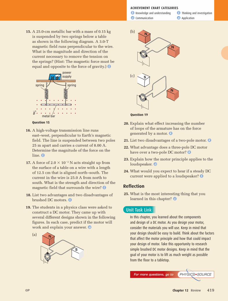
15. A 25.0-cm metallic bar with a mass of 0.15 kgis suspended by two springs below a table as shown in the following diagram. A 3.0-T magnetic field runs perpendicular to the wire. What is the magnitude and direction of the current necessary to remove the tension on the springs? (Hint: The magnetic force must be equal and opposite to the force of gravity.) t
16. A high-voltage transmission line runs east–west, perpendicular to Earth’s magnetic field. The line is suspended between two poles 25 m apart and carries a current of 8.00 A. Determine the magnitude of the force on the line. t
17. A force of 2.0 � 10�2 N acts straight up from the surface of a table on a wire with a length of 12.5 cm that is aligned north–south. The current in the wire is 25.0 A from north to south. What is the strength and direction of the magnetic field that surrounds the wire? t
18. List two advantages and two disadvantages of brushed DC motors. t
19. The students in a physics class were asked to construct a DC motor. They came up with several different designs shown in the following figures. In each case, predict if the motor will work and explain your answer. a
(a)
(b)
(c)
20. Explain what effect increasing the number of loops of the armature has on the force generated by a motor. k
21. List two disadvantages of a two-pole motor. k
22. What advantage does a three-pole DC motor have over a two-pole DC motor? k
23. Explain how the motor principle applies to the loudspeaker. a
24. What would you expect to hear if a steady DC current were applied to a loudspeaker? t
Reflection
25. What is the most interesting thing that you learned in this chapter? c
powersupply
metal bar
spring
B
spring
N
N
Question 19
S
N
For more questions, go to PHYSICS•SOURCE
N
S
ACHIEVEMENT CHART CATEGORIESk Knowledge and understanding t Thinking and investigation
c Communication a Application
Question 15
Unit Task Link
In this chapter, you learned about the components
and design of a DC motor. As you design your motor,
consider the materials you will use. Keep in mind that
your design should be easy to build. Think about the factors
that affect the motor principle and how that could impact
your design of motor. Take this opportunity to research
simple brushed DC motor designs. Keep in mind that the
goal of your motor is to lift as much weight as possible
from the floor to a tabletop.
12-PHYSICS-11SE-Ch12.indd 41912-PHYSICS-11SE-Ch12.indd 419 7/26/10 10:04:37 AM7/26/10 10:04:37 AM