Embed Size (px)
Citation preview

1
2004 Deitel & Associates, Inc. All rights reserved.
Chapter 12 – Disk Performance Optimization
Outline12.1 Introduction12.2 Evolution of Secondary Storage12.3 Characteristics of Moving-Head Disk Storage12.4 Why Disk Scheduling Is Necessary12.5 Disk Scheduling Strategies12.5.1 First-Come-First-Served (FCFS) Disk Scheduling12.5.2 Shortest-Seek-Time-First (SSTF) Disk Scheduling12.5.3 SCAN Disk Scheduling12.5.4 C-SCAN Disk Scheduling12.5.5 FSCAN and N-Step SCAN Disk Scheduling12.5.6 LOOK and C-LOOK Disk Scheduling12.6 Rotational Optimization12.6.1 SLTF Scheduling12.6.2 SPTF and SATF Scheduling
2004 Deitel & Associates, Inc. All rights reserved.
Chapter 12 – Disk Performance Optimization
Outline (cont.)12.7 System Considerations12.8 Caching and Buffering12.9 Other Disk Performance Techniques12.10 Redundant Arrays of Independent Disks (RAID)12.10.1 RAID Overview12.10.2 Level 0 (Striping)12.10.3 Level 1 (Mirroring)12.10.4 Level 2 (Bit-Level Hamming ECC Parity)12.10.5 Level 3 (Bit-Level XOR ECC Parity)12.10.6 Level 4 (Block-Level XOR ECC Parity)12.10.7 Level 5 (Block-Level Distributed XOR ECC Parity)

2
2004 Deitel & Associates, Inc. All rights reserved.
Objectives
• After reading this chapter, you should understand:– how disk input/output is accomplished.– the importance of optimizing disk performance.– seek optimization and rotational optimization.– various disk scheduling strategies.– caching and buffering.– other disk performance improvement techniques.– key schemes for implementing redundant arrays of independent
disks (RAID).
2004 Deitel & Associates, Inc. All rights reserved.
12.1 Introduction
• Secondary storage is one common bottleneck– Improvements in secondary storage performance significantly
boost overall system performance– Solutions can be both software- and hardware-based

3
2004 Deitel & Associates, Inc. All rights reserved.
12.2 Evolution of Secondary Storage
• Most secondary storage devices involve magnetic media– Data accessed by read-write head– Early technologies used sequential storage
• Records must be accessed one-by-one in order• Inefficient for direct-access applications
– Random-access storage• Also called direct-access storage• Records can be accessed in any order
2004 Deitel & Associates, Inc. All rights reserved.
12.3 Characteristics of Moving-Head Disk Storage
• Physical layout of disk drives– Set of magnetic platters
• Rotate on spindle• Made up of tracks, which in turn contain sectors• Vertical sets of tracks form cylinders

4
2004 Deitel & Associates, Inc. All rights reserved.
Figure 12.1 Schematic side view of a moving-head disk.
12.3 Characteristics of Moving-Head Disk Storage
2004 Deitel & Associates, Inc. All rights reserved.
12.3 Characteristics of Moving-Head Disk Storage
• Performance measurements– Rotational latency
• Time for data to rotate from current position to read-write head– Seek time
• Time for read-write head to move to new cylinder– Transmission time
• Time for all desired data to spin by read-write head

5
2004 Deitel & Associates, Inc. All rights reserved.
Figure 12.2 Hard disk track-to-track seek times and latency times.
12.3 Characteristics of Moving-Head Disk Storage
2004 Deitel & Associates, Inc. All rights reserved.
12.3 Characteristics of Moving-Head Disk Storage
• Disks divide tracks into several sectors, each typically containing 512 bytes

6
2004 Deitel & Associates, Inc. All rights reserved.
Figure 12.3 Schematic top view of a disk surface.
12.3 Characteristics of Moving-Head Disk Storage
2004 Deitel & Associates, Inc. All rights reserved.
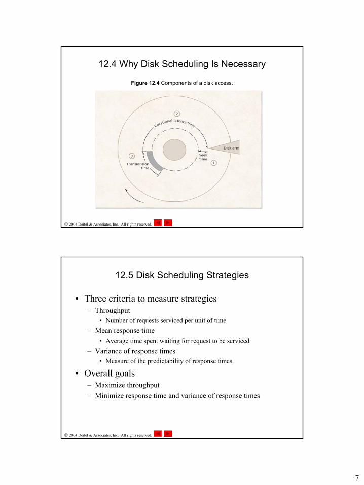
12.4 Why Disk Scheduling Is Necessary
• First-come-first-served (FCFS) scheduling has major drawbacks– Seeking to randomly distributed locations results in long waiting times– Under heavy loads, system can become overwhelmed
• Requests must be serviced in logical order to minimize delays– Service requests with least mechanical motion
• The first disk scheduling algorithms concentrated on minimizing seek times, the component of disk access that had the highest latency
• Modern systems perform rotational optimization as well
7
2004 Deitel & Associates, Inc. All rights reserved.
Figure 12.4 Components of a disk access.
12.4 Why Disk Scheduling Is Necessary
2004 Deitel & Associates, Inc. All rights reserved.
12.5 Disk Scheduling Strategies
• Three criteria to measure strategies– Throughput
• Number of requests serviced per unit of time– Mean response time
• Average time spent waiting for request to be serviced– Variance of response times
• Measure of the predictability of response times
• Overall goals– Maximize throughput– Minimize response time and variance of response times

8
2004 Deitel & Associates, Inc. All rights reserved.
Figure 12.5 Disk request pattern.
12.5 Disk Scheduling Strategies
2004 Deitel & Associates, Inc. All rights reserved.
12.5.1 First-Come-First-Served (FCFS) Disk Scheduling
• FCFS scheduling: Requests serviced in order of arrival– Advantages
• Fair• Prevents indefinite postponement• Low overhead
– Disadvantages• Potential for extremely low throughput
– FCFS typically results in a random seek pattern because it does not reorder requests to reduce service delays

9
2004 Deitel & Associates, Inc. All rights reserved.
Figure 12.6 Seek pattern under the FCFS strategy.
12.5.1 First-Come-First-Served (FCFS) Disk Scheduling
2004 Deitel & Associates, Inc. All rights reserved.
12.5.2 Shortest-Seek-Time-First
• SSTF: Service request closest to read-write head– Advantages
• Higher throughput and lower response times than FCFS• Reasonable solution for batch processing systems
– Disadvantages• Does not ensure fairness• Possibility of indefinite postponement• High variance of response times• Response time generally unacceptable for interactive systems

10
2004 Deitel & Associates, Inc. All rights reserved.
Figure 12.7 Seek pattern under the SSTF strategy.
12.5.2 Shortest-Seek-Time-First
2004 Deitel & Associates, Inc. All rights reserved.
12.5.3 SCAN Disk Scheduling
• SCAN: Shortest seek time in preferred direction– Does not change direction until edge of disk reached– Similar characteristics to SSTF– Indefinite postponement still possible– Offers an improved variance of response times

11
2004 Deitel & Associates, Inc. All rights reserved.
Figure 12.8 Seek pattern under the SCAN strategy.
12.5.3 SCAN Disk Scheduling
2004 Deitel & Associates, Inc. All rights reserved.
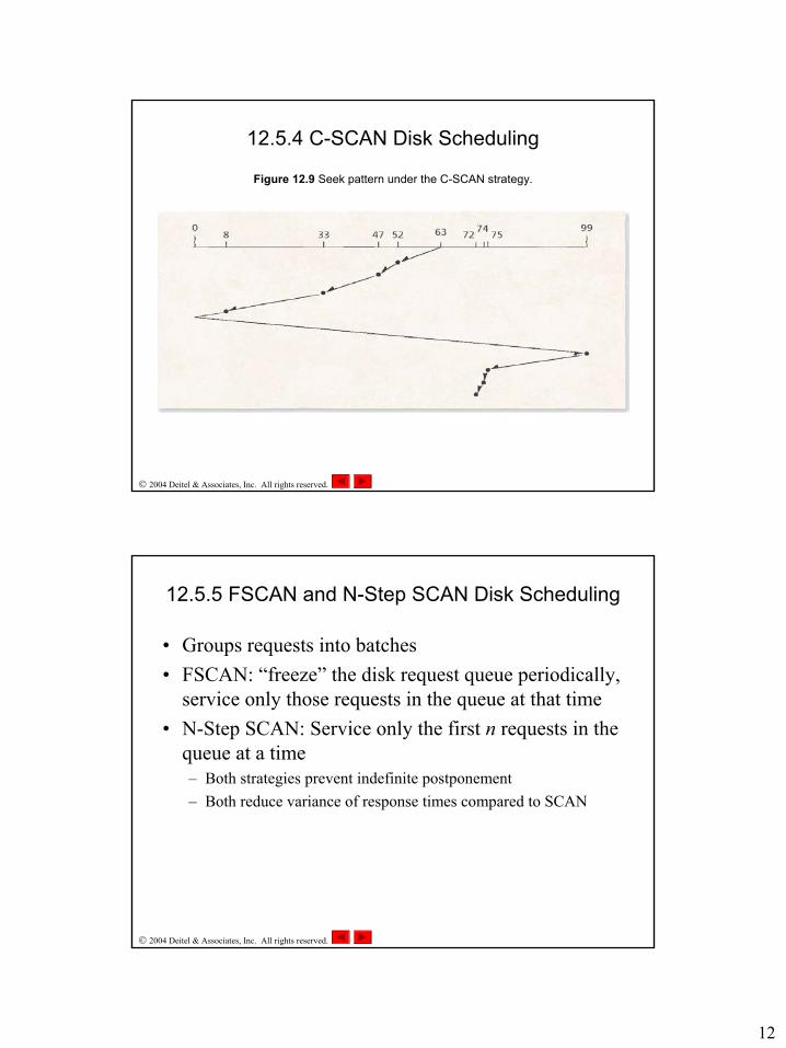
12.5.4 C-SCAN Disk Scheduling
• C-SCAN: Similar to SCAN, but at the end of an inward sweep, the disk arm jumps (without servicing requests) to the outermost cylinder– Further reduces variance of response times as the expense of
throughput and mean response times
12
2004 Deitel & Associates, Inc. All rights reserved.
Figure 12.9 Seek pattern under the C-SCAN strategy.
12.5.4 C-SCAN Disk Scheduling
2004 Deitel & Associates, Inc. All rights reserved.
12.5.5 FSCAN and N-Step SCAN Disk Scheduling
• Groups requests into batches• FSCAN: “freeze” the disk request queue periodically,
service only those requests in the queue at that time• N-Step SCAN: Service only the first n requests in the
queue at a time– Both strategies prevent indefinite postponement– Both reduce variance of response times compared to SCAN

13
2004 Deitel & Associates, Inc. All rights reserved.
Figure 12.10 Seek pattern under the FSCAN strategy.
12.5.5 FSCAN and N-Step SCAN Disk Scheduling
2004 Deitel & Associates, Inc. All rights reserved.
Figure 12.11 Seek pattern under the N-Step SCAN strategy (n = 3).
12.5.5 FSCAN and N-Step SCAN Disk Scheduling

14
2004 Deitel & Associates, Inc. All rights reserved.
12.5.6 LOOK and C-LOOK Disk Scheduling
• LOOK: Improvement on SCAN scheduling– Only performs sweeps large enough to service all requests
• Does move the disk arm to the outer edges of the disk if no requests for those regions are pending
• Improves efficiency by avoiding unnecessary seek operations• High throughput
• C-LOOK improves C-SCAN scheduling– Combination of LOOK and C-SCAN– Lower variance of response times than LOOK, at the expense of
throughput
2004 Deitel & Associates, Inc. All rights reserved.
Figure 12.12 Seek pattern under the LOOK strategy.
12.5.6 LOOK and C-LOOK Disk Scheduling

15
2004 Deitel & Associates, Inc. All rights reserved.
Figure 12.13 Seek optimization strategies summary.
12.5.6 LOOK and C-LOOK Disk Scheduling
2004 Deitel & Associates, Inc. All rights reserved.
12.6 Rotational Optimization
• Seek time formerly dominated performance concerns– Today, seek times and rotational latency are the same order of
magnitude• Recently developed strategies attempt to optimization disk
performance by reducing rotational latency• Important when accessing small pieces of data distributed
throughout the disk surfaces

16
2004 Deitel & Associates, Inc. All rights reserved.
12.6.1 SLTF Scheduling
• Shortest-latency-time-first scheduling– On a given cylinder, service request with shortest rotational
latency first– Easy to implement– Achieves near-optimal performance for rotational latency
2004 Deitel & Associates, Inc. All rights reserved.
Figure 12.14 SLTF scheduling. The requests will be serviced in the indicated order regardless of the order in which they arrived.
12.6.1 SLTF Scheduling

17
2004 Deitel & Associates, Inc. All rights reserved.
12.6.2 SPTF and SATF Scheduling
• Shortest-positioning-time-first scheduling– Positioning time: Sum of seek time and rotational latency– SPTF first services the request with the shortest positioning time– Yields good performance– Can indefinitely postpone requests
2004 Deitel & Associates, Inc. All rights reserved.
12.6.2 SPTF and SATF Scheduling
• Shortest-access-time-first scheduling– Access time: positioning time plus transmission time– High throughput
• Again, possible to indefinitely postpone requests
• Both SPTF and SATF can implement LOOK to improve performance
• Weakness– Both SPTF and SATF require knowledge of disk performance
characteristics which might not be readily available due to error-correcting data and transparent reassignment of bad sectors

18
2004 Deitel & Associates, Inc. All rights reserved.
Figure 12.15 SPTF (a) and SATF (b) disk scheduling examples.
12.6.2 SPTF and SATF Scheduling
2004 Deitel & Associates, Inc. All rights reserved.
12.7 System Considerations
• Disk scheduling is frequently, but not always, helpful– Will not help appreciably in processor-bound systems– High loads of small transactions to randomly distributed location
will benefit– On fairly uniform, nonrandom distributions, scheduling
overhead can degrade performance– File organization techniques sometimes counteract scheduling
algorithms

19
2004 Deitel & Associates, Inc. All rights reserved.
12.8 Caching and Buffering
• Cache buffer: Store copy of disk data in faster memory– Located in main memory, onboard cache, or on disk controller– Vastly faster access times than access to disk– Can be used as a buffer to delay writing of data until disk is under light
load• Potential for inconsistency
– Contents of main memory could be lost in power outage or system failure
– Write-back caching• Data not written to disk immediately• Flushed periodically
– Write-through caching• Writes to disk and cache simultaneously• Reduces performance compared to write-back, but guarantees consistency
2004 Deitel & Associates, Inc. All rights reserved.
12.9 Other Disk Performance Techniques
• Other ways of optimizing disk performance– Defragmentation
• Place related data in contiguous sectors• Decreases number of seek operations required• Partitioning can help reduce fragmentation
– Compression• Data consumes less disk space• Improves transfer and access times• Increased execution-time overhead to perform
compression/decompression

20
2004 Deitel & Associates, Inc. All rights reserved.
12.9 Other Disk Performance Techniques
• Other ways of optimizing disk performance (cont.)– Multiple copies of frequently-accessed data
• Access the copy that is closest to read-write head• Can incur significant storage overhead
– Record blocking• Read/write multiple records as single block of data
– Disk arm anticipation• When idle, move disk arm to location of data that is most likely to
be accessed next• If the disk arm incorrectly predicts future disk accesses,
performance can significantly degrade
2004 Deitel & Associates, Inc. All rights reserved.
12.10 Redundant Arrays of Independent Disks
• Patterson et al. observed that memory and processor speeds tend to increase much faster than disk I/O speeds
• RAID developed to avoid the “pending I/O” crisis – Attempts to improve disk performance and/or reliability– Multiple disks in an array can be accessed simultaneously– Performs accesses in parallel to increase throughput– Additional drives can be used to improve data integrity

21
2004 Deitel & Associates, Inc. All rights reserved.
12.10.1 RAID Overview
• Common RAID characteristics– Data stored in strips
• Spread across set of disks– Strips form stripes
• Set of strips at same location on each disk– Fine-grained strip
• Yields high transfer rates (many disks service request at once)• Array can only process one request at once
– Coarse-grained strips• Might fit an entire file on one disk• Allow multiple requests to be filled at once
2004 Deitel & Associates, Inc. All rights reserved.
Figure 12.16 Strips and stripe created from a single file in RAID systems.
12.10.1 RAID Overview

22
2004 Deitel & Associates, Inc. All rights reserved.
12.10.1 RAID Overview
• Potential drawbacks– Larger number of disks decreases mean-time-to-failure (MTTF)
• More disks provide more points of failure• Data stored in many RAID levels can be lost if more than one drive
in array fails
2004 Deitel & Associates, Inc. All rights reserved.
12.10.1 RAID Overview
• Related technologies– Disk mirroring
• One disk is simply a copy of another• Simple way to achieve redundancy and fault tolerance, but incurs
significant storage overhead– RAID controller
• Special-purpose hardware dedicated to RAID operations• Offloads most responsibility from operating system/processor• Can be expensive

23
2004 Deitel & Associates, Inc. All rights reserved.
12.10.2 Level 0 (Striping)
• Level 0– Simplest RAID implementation– Includes striping but no redundancy (not a “true” RAID level)– Highest-performing RAID level for a fixed number of disks– High risk of data loss
• Multiple drives involved• Could lose all data in array with one drive failure
– Appropriate where performance greatly outweighs reliability
2004 Deitel & Associates, Inc. All rights reserved.
Figure 12.17 RAID level 0 (striping).
12.10.2 Level 0 (Striping)

24
2004 Deitel & Associates, Inc. All rights reserved.
12.10.3 Level 1 (Mirroring)
• Level 1– Highest level of redundancy/fault tolerance for traditional RAID
levels– Each drive has a mirrored copy in array– No striping at this level
• Improves read performance over single disks because multiple disks can be read at once
• Slower write performance because two disks must be accessed for each modified data item to maintain mirroring
– High storage overhead• Only half array stores unique data
– Most suitable where reliability is primary concern
2004 Deitel & Associates, Inc. All rights reserved.
Figure 12.18 RAID level 1 (mirroring).
12.10.3 Level 1 (Mirroring)
25
2004 Deitel & Associates, Inc. All rights reserved.
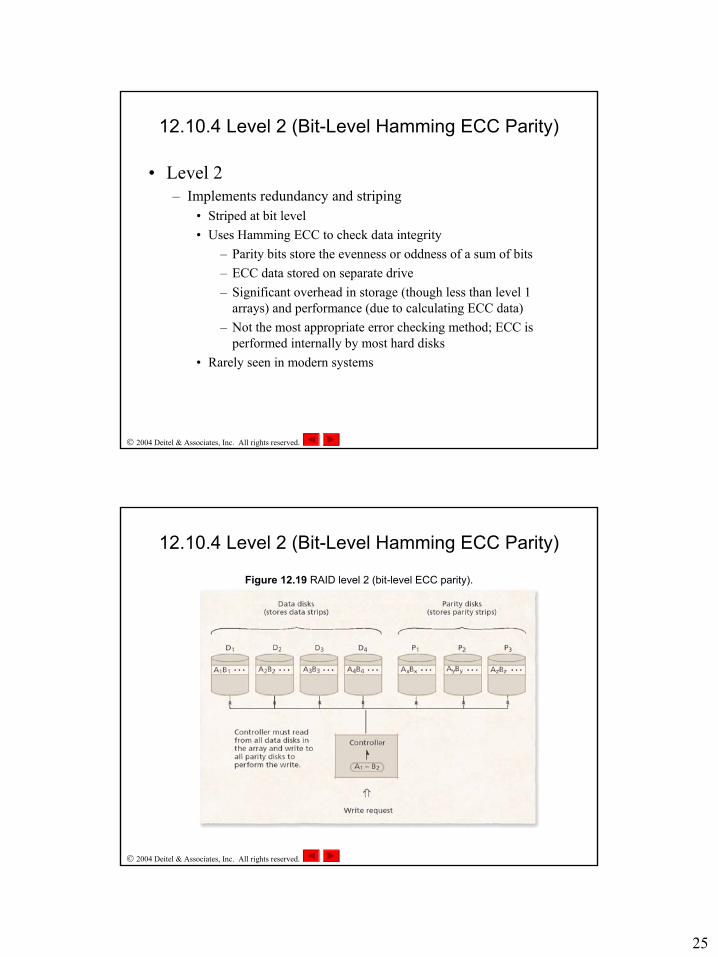
12.10.4 Level 2 (Bit-Level Hamming ECC Parity)
• Level 2– Implements redundancy and striping
• Striped at bit level• Uses Hamming ECC to check data integrity
– Parity bits store the evenness or oddness of a sum of bits– ECC data stored on separate drive– Significant overhead in storage (though less than level 1
arrays) and performance (due to calculating ECC data)– Not the most appropriate error checking method; ECC is
performed internally by most hard disks• Rarely seen in modern systems
2004 Deitel & Associates, Inc. All rights reserved.
Figure 12.19 RAID level 2 (bit-level ECC parity).
12.10.4 Level 2 (Bit-Level Hamming ECC Parity)

26
2004 Deitel & Associates, Inc. All rights reserved.
12.10.5 Level 3 (Bit-Level XOR ECC Parity)
• Level 3– Also stripes at the bit level– Uses XOR to calculate parity for ECC
• Much simpler than Hamming ECC• Requires only one disk for parity information regardless of the size
of the array• Cannot determine which bit contains error, but this information can
be gathered easily by inspecting the array for a failed disk• High transfer rates, but only one request serviced at a time
2004 Deitel & Associates, Inc. All rights reserved.
Figure 12.20 RAID level 3 (bit-level, single parity disk).
12.10.5 Level 3 (Bit-Level XOR ECC Parity)

27
2004 Deitel & Associates, Inc. All rights reserved.
12.10.6 Level 4 (Block-Level XOR ECC Parity)
• Level 4– Similar to RAID level 3
• Stores larger strips than other levels• Can service more requests simultaneously as files are more likely to
be on one disk• Write requests must be performed one at a time
– Restriction eliminated in level 5• Rarely implemented because level 5 is similar but superior
2004 Deitel & Associates, Inc. All rights reserved.
Figure 12.21 RAID level 4 (block-level parity).
12.10.6 Level 4 (Block-Level XOR ECC Parity)

28
2004 Deitel & Associates, Inc. All rights reserved.
12.10.7 Level 5 (Block-Level Distributed XOR ECC Parity)
• Level 5– Similar to level 4
• Removes write bottleneck of RAID level 4, because parity blocks are distributed across disks
• Still must update parity information– For many small write operations, overhead can be substantial– Caching mechanisms can help alleviate this
• For example, parity logging, update image and AFRAID• Faster and more reliable than levels 2–4
– Costlier and more complex as well– Among most commonly implemented RAID levels
2004 Deitel & Associates, Inc. All rights reserved.
Figure 12.22 RAID level 5 (block-level distributed parity).
12.10.7 Level 5 (Block-Level Distributed XOR ECC Parity)

29
2004 Deitel & Associates, Inc. All rights reserved.
Figure 12.23 Comparison of RAID levels 0-5.
12.10.7 Level 5 (Block-Level Distributed XOR ECC Parity)
2004 Deitel & Associates, Inc. All rights reserved.
• Other RAID levels exist– No standard naming convention– RAID level 6 provides additional parity information to improve
fault tolerance– RAID level 0 + 1: set of striped disks that are copied to set of
mirror disks– RAID level 10: set of mirrored data that is striped across a set of
disks– Others include 0+3, 0+5, 50, 1+5, 51, 53 and RAID level 7
12.10.7 Level 5 (Block-Level Distributed XOR ECC Parity)