Embed Size (px)
Citation preview
Chapter 11REFRIGERATION CYCLES
| 607
Amajor application area of thermodynamics is refrigera-
tion, which is the transfer of heat from a lower temper-
ature region to a higher temperature one. Devices that
produce refrigeration are called refrigerators, and the cycles on
which they operate are called refrigeration cycles. The most
frequently used refrigeration cycle is the vapor-compression
refrigeration cycle in which the refrigerant is vaporized and
condensed alternately and is compressed in the vapor phase.
Another well-known refrigeration cycle is the gas refrigeration
cycle in which the refrigerant remains in the gaseous phase
throughout. Other refrigeration cycles discussed in this chapter
are cascade refrigeration, where more than one refrigeration
cycle is used; absorption refrigeration, where the refrigerant is
dissolved in a liquid before it is compressed; and, as a Topic of
Special Interest, thermoelectric refrigeration, where refrigera-
tion is produced by the passage of electric current through two
dissimilar materials.
Objectives
The objectives of Chapter 11 are to:
• Introduce the concepts of refrigerators and heat pumps and
the measure of their performance.
• Analyze the ideal vapor-compression refrigeration cycle.
• Analyze the actual vapor-compression refrigeration cycle.
• Review the factors involved in selecting the right refrigerant
for an application.
• Discuss the operation of refrigeration and heat pump
systems.
• Evaluate the performance of innovative vapor-compression
refrigeration systems.
• Analyze gas refrigeration systems.
• Introduce the concepts of absorption-refrigeration systems.
• Review the concepts of thermoelectric power generation
and refrigeration.
11–1 ■ REFRIGERATORS AND HEAT PUMPS
We all know from experience that heat flows in the direction of decreasing
temperature, that is, from high-temperature regions to low-temperature ones.
This heat-transfer process occurs in nature without requiring any devices.
The reverse process, however, cannot occur by itself. The transfer of heat
from a low-temperature region to a high-temperature one requires special
devices called refrigerators.
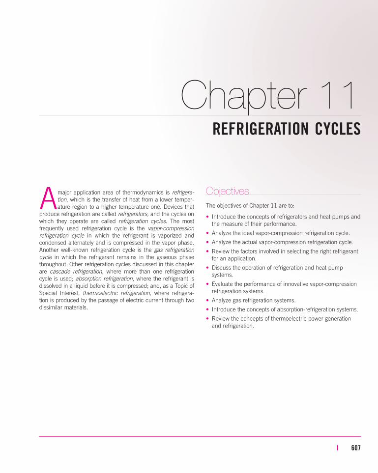
Refrigerators are cyclic devices, and the working fluids used in the refrig-
eration cycles are called refrigerants. A refrigerator is shown schematically
in Fig. 11–1a. Here QL is the magnitude of the heat removed from the refrig-
erated space at temperature TL ,QH is the magnitude of the heat rejected to
the warm space at temperature TH , and Wnet,in is the net work input to the
refrigerator. As discussed in Chap. 6, QL and QH represent magnitudes and
thus are positive quantities.
Another device that transfers heat from a low-temperature medium to a
high-temperature one is the heat pump. Refrigerators and heat pumps are
essentially the same devices; they differ in their objectives only. The objec-
tive of a refrigerator is to maintain the refrigerated space at a low tempera-
ture by removing heat from it. Discharging this heat to a higher-temperature
medium is merely a necessary part of the operation, not the purpose. The
objective of a heat pump, however, is to maintain a heated space at a high
temperature. This is accomplished by absorbing heat from a low-temperature
source, such as well water or cold outside air in winter, and supplying this
heat to a warmer medium such as a house (Fig. 11–1b).
The performance of refrigerators and heat pumps is expressed in terms of
the coefficient of performance (COP), defined as
(11–1)
(11–2)
These relations can also be expressed in the rate form by replacing the
quantities QL, QH, and Wnet,in by Q.L, Q
.H, and W
.net,in, respectively. Notice that
both COPR and COPHP can be greater than 1. A comparison of Eqs. 11–1
and 11–2 reveals that
(11–3)
for fixed values of QL and QH. This relation implies that COPHP � 1 since
COPR is a positive quantity. That is, a heat pump functions, at worst, as a
resistance heater, supplying as much energy to the house as it consumes. In
reality, however, part of QH is lost to the outside air through piping and
other devices, and COPHP may drop below unity when the outside air tem-
perature is too low. When this happens, the system normally switches to the
fuel (natural gas, propane, oil, etc.) or resistance-heating mode.
The cooling capacity of a refrigeration system—that is, the rate of heat
removal from the refrigerated space—is often expressed in terms of tons of
refrigeration. The capacity of a refrigeration system that can freeze 1 ton
(2000 lbm) of liquid water at 0°C (32°F) into ice at 0°C in 24 h is said to be
COPHP � COPR � 1
COPHP �Desired output
Required input�
Heating effect
Work input�
QH
Wnet,in
COPR �Desired output
Required input�
Cooling effect
Work input�
QL
Wnet,in
608 | Thermodynamics
WARMhouse
WARM
environment
COLDrefrigerated
space
COLDenvironment
(a) Refrigerator (b) Heat pump
QH
(desired
output)
HPR
QH
QL
(desired
output)
QL
Wnet,in
(required
input)
Wnet,in
(required
input)
FIGURE 11–1
The objective of a refrigerator is to
remove heat (QL) from the cold
medium; the objective of a heat pump
is to supply heat (QH) to a warm
medium.
SEE TUTORIAL CH. 11, SEC. 1 ON THE DVD.
INTERACTIVE
TUTORIAL
1 ton. One ton of refrigeration is equivalent to 211 kJ/min or 200 Btu/min.
The cooling load of a typical 200-m2 residence is in the 3-ton (10-kW)
range.
11–2 ■ THE REVERSED CARNOT CYCLE
Recall from Chap. 6 that the Carnot cycle is a totally reversible cycle that
consists of two reversible isothermal and two isentropic processes. It has the
maximum thermal efficiency for given temperature limits, and it serves as a
standard against which actual power cycles can be compared.
Since it is a reversible cycle, all four processes that comprise the Carnot
cycle can be reversed. Reversing the cycle does also reverse the directions
of any heat and work interactions. The result is a cycle that operates in the
counterclockwise direction on a T-s diagram, which is called the reversed
Carnot cycle. A refrigerator or heat pump that operates on the reversed
Carnot cycle is called a Carnot refrigerator or a Carnot heat pump.
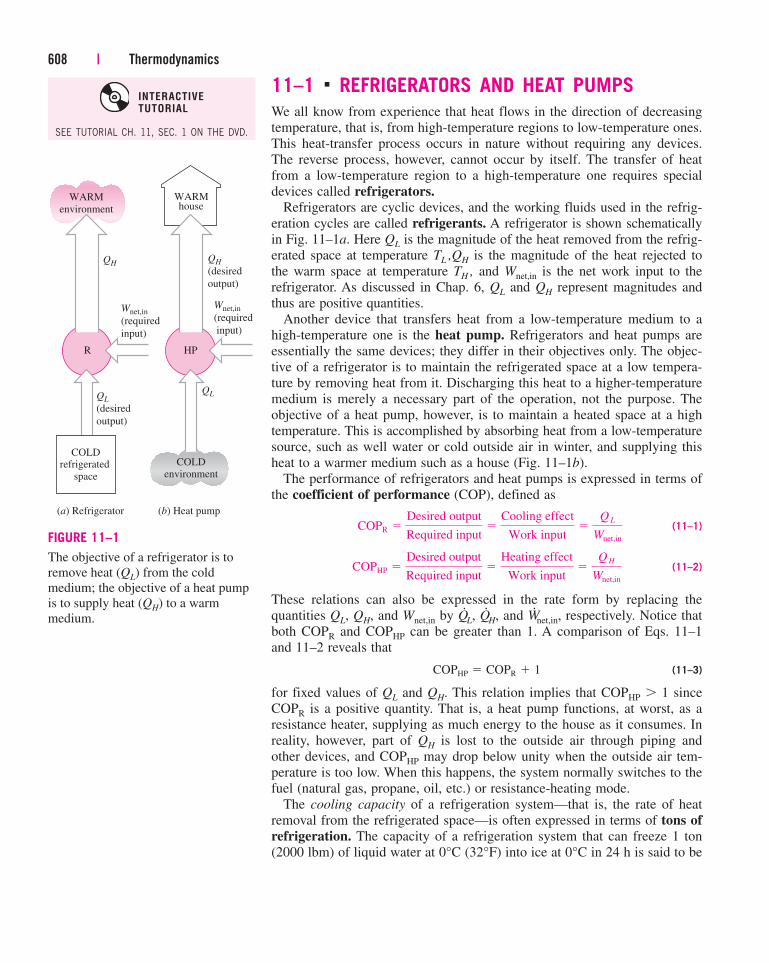
Consider a reversed Carnot cycle executed within the saturation dome of a
refrigerant, as shown in Fig. 11–2. The refrigerant absorbs heat isothermally
from a low-temperature source at TL in the amount of QL (process 1-2), is
compressed isentropically to state 3 (temperature rises to TH), rejects heat
isothermally to a high-temperature sink at TH in the amount of QH (process
3-4), and expands isentropically to state 1 (temperature drops to TL). The
refrigerant changes from a saturated vapor state to a saturated liquid state in
the condenser during process 3-4.
Chapter 11 | 609
QH
2
TH
Condenser
WARM medium
at TH
COLD medium
at TL
QL
QH
QL
4 3
21
T
s
EvaporatorTL
Turbine Compressor
1
34
FIGURE 11–2
Schematic of a Carnot refrigerator and T-s diagram of the reversed Carnot cycle.
The coefficients of performance of Carnot refrigerators and heat pumps
are expressed in terms of temperatures as
(11–4)
and
(11–5)
Notice that both COPs increase as the difference between the two tempera-
tures decreases, that is, as TL rises or TH falls.
The reversed Carnot cycle is the most efficient refrigeration cycle operating
between two specified temperature levels. Therefore, it is natural to look at it
first as a prospective ideal cycle for refrigerators and heat pumps. If we could,
we certainly would adapt it as the ideal cycle. As explained below, however,
the reversed Carnot cycle is not a suitable model for refrigeration cycles.
The two isothermal heat transfer processes are not difficult to achieve in
practice since maintaining a constant pressure automatically fixes the tem-
perature of a two-phase mixture at the saturation value. Therefore, processes
1-2 and 3-4 can be approached closely in actual evaporators and condensers.
However, processes 2-3 and 4-1 cannot be approximated closely in practice.
This is because process 2-3 involves the compression of a liquid–vapor mix-
ture, which requires a compressor that will handle two phases, and process
4-1 involves the expansion of high-moisture-content refrigerant in a turbine.
It seems as if these problems could be eliminated by executing the
reversed Carnot cycle outside the saturation region. But in this case we have
difficulty in maintaining isothermal conditions during the heat-absorption
and heat-rejection processes. Therefore, we conclude that the reversed Car-
not cycle cannot be approximated in actual devices and is not a realistic
model for refrigeration cycles. However, the reversed Carnot cycle can serve
as a standard against which actual refrigeration cycles are compared.
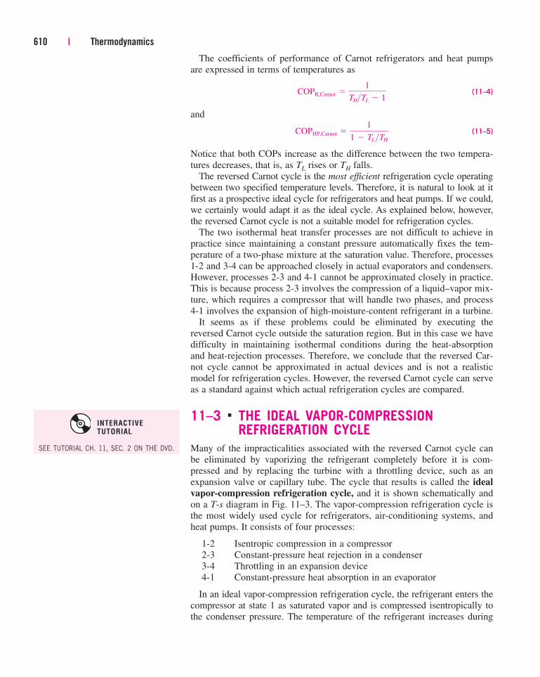
11–3 ■ THE IDEAL VAPOR-COMPRESSIONREFRIGERATION CYCLE
Many of the impracticalities associated with the reversed Carnot cycle can
be eliminated by vaporizing the refrigerant completely before it is com-
pressed and by replacing the turbine with a throttling device, such as an
expansion valve or capillary tube. The cycle that results is called the ideal
vapor-compression refrigeration cycle, and it is shown schematically and
on a T-s diagram in Fig. 11–3. The vapor-compression refrigeration cycle is
the most widely used cycle for refrigerators, air-conditioning systems, and
heat pumps. It consists of four processes:
1-2 Isentropic compression in a compressor
2-3 Constant-pressure heat rejection in a condenser
3-4 Throttling in an expansion device
4-1 Constant-pressure heat absorption in an evaporator
In an ideal vapor-compression refrigeration cycle, the refrigerant enters the
compressor at state 1 as saturated vapor and is compressed isentropically to
the condenser pressure. The temperature of the refrigerant increases during
COPHP,Carnot �1
1 � TL >TH
COPR,Carnot �1
TH>TL � 1
610 | Thermodynamics
SEE TUTORIAL CH. 11, SEC. 2 ON THE DVD.
INTERACTIVE
TUTORIAL
this isentropic compression process to well above the temperature of the sur-
rounding medium. The refrigerant then enters the condenser as superheated
vapor at state 2 and leaves as saturated liquid at state 3 as a result of heat
rejection to the surroundings. The temperature of the refrigerant at this state
is still above the temperature of the surroundings.
The saturated liquid refrigerant at state 3 is throttled to the evaporator
pressure by passing it through an expansion valve or capillary tube. The
temperature of the refrigerant drops below the temperature of the refriger-
ated space during this process. The refrigerant enters the evaporator at state
4 as a low-quality saturated mixture, and it completely evaporates by
absorbing heat from the refrigerated space. The refrigerant leaves the evapo-
rator as saturated vapor and reenters the compressor, completing the cycle.
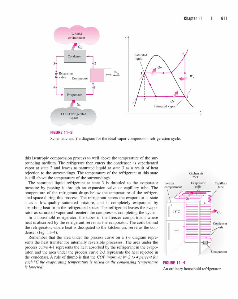
In a household refrigerator, the tubes in the freezer compartment where
heat is absorbed by the refrigerant serves as the evaporator. The coils behind
the refrigerator, where heat is dissipated to the kitchen air, serve as the con-
denser (Fig. 11–4).
Remember that the area under the process curve on a T-s diagram repre-
sents the heat transfer for internally reversible processes. The area under the
process curve 4-1 represents the heat absorbed by the refrigerant in the evapo-
rator, and the area under the process curve 2-3 represents the heat rejected in
the condenser. A rule of thumb is that the COP improves by 2 to 4 percent for
each °C the evaporating temperature is raised or the condensing temperature
is lowered.
Chapter 11 | 611
QH
QL4
3
2
1
T
s
4'
Saturated vapor
Saturatedliquid
Compressor
QH
2
Condenser
WARM
environment
QL
Evaporator
1
COLD refrigerated
space
WinExpansion
valve
4
3
Win
FIGURE 11–3
Schematic and T-s diagram for the ideal vapor-compression refrigeration cycle.
Compressor
Condensercoils
Kitchen air25°C
Capillarytube
Evaporatorcoils
Freezercompartment
–18°C
3°C
QH
QL
FIGURE 11–4
An ordinary household refrigerator.
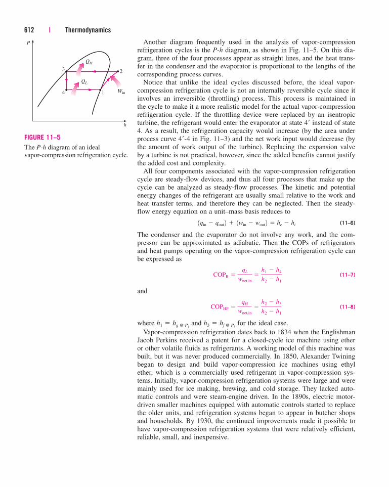
Another diagram frequently used in the analysis of vapor-compression
refrigeration cycles is the P-h diagram, as shown in Fig. 11–5. On this dia-
gram, three of the four processes appear as straight lines, and the heat trans-
fer in the condenser and the evaporator is proportional to the lengths of the
corresponding process curves.
Notice that unlike the ideal cycles discussed before, the ideal vapor-
compression refrigeration cycle is not an internally reversible cycle since it
involves an irreversible (throttling) process. This process is maintained in
the cycle to make it a more realistic model for the actual vapor-compression
refrigeration cycle. If the throttling device were replaced by an isentropic
turbine, the refrigerant would enter the evaporator at state 4� instead of state
4. As a result, the refrigeration capacity would increase (by the area under
process curve 4�-4 in Fig. 11–3) and the net work input would decrease (by
the amount of work output of the turbine). Replacing the expansion valve
by a turbine is not practical, however, since the added benefits cannot justify
the added cost and complexity.
All four components associated with the vapor-compression refrigeration
cycle are steady-flow devices, and thus all four processes that make up the
cycle can be analyzed as steady-flow processes. The kinetic and potential
energy changes of the refrigerant are usually small relative to the work and
heat transfer terms, and therefore they can be neglected. Then the steady-
flow energy equation on a unit–mass basis reduces to
(11–6)
The condenser and the evaporator do not involve any work, and the com-
pressor can be approximated as adiabatic. Then the COPs of refrigerators
and heat pumps operating on the vapor-compression refrigeration cycle can
be expressed as
(11–7)
and
(11–8)
where and for the ideal case.
Vapor-compression refrigeration dates back to 1834 when the Englishman
Jacob Perkins received a patent for a closed-cycle ice machine using ether
or other volatile fluids as refrigerants. A working model of this machine was
built, but it was never produced commercially. In 1850, Alexander Twining
began to design and build vapor-compression ice machines using ethyl
ether, which is a commercially used refrigerant in vapor-compression sys-
tems. Initially, vapor-compression refrigeration systems were large and were
mainly used for ice making, brewing, and cold storage. They lacked auto-
matic controls and were steam-engine driven. In the 1890s, electric motor-
driven smaller machines equipped with automatic controls started to replace
the older units, and refrigeration systems began to appear in butcher shops
and households. By 1930, the continued improvements made it possible to
have vapor-compression refrigeration systems that were relatively efficient,
reliable, small, and inexpensive.
h3 � hf @ P3h1 � hg @ P1
COPHP �qH
wnet,in
�h2 � h3
h2 � h1
COPR �qL
wnet,in
�h1 � h4
h2 � h1
1qin � qout 2 � 1win � wout 2 � he � hi
612 | Thermodynamics
1
h
23
4
P
QH
QL
Win
FIGURE 11–5
The P-h diagram of an ideal
vapor-compression refrigeration cycle.
Chapter 11 | 613
EXAMPLE 11–1 The Ideal Vapor-Compression Refrigeration
Cycle
A refrigerator uses refrigerant-134a as the working fluid and operates on an
ideal vapor-compression refrigeration cycle between 0.14 and 0.8 MPa. If the
mass flow rate of the refrigerant is 0.05 kg/s, determine (a) the rate of heat
removal from the refrigerated space and the power input to the compressor,
(b) the rate of heat rejection to the environment, and (c) the COP of the
refrigerator.
Solution A refrigerator operates on an ideal vapor-compression refrigeration
cycle between two specified pressure limits. The rate of refrigeration, the
power input, the rate of heat rejection, and the COP are to be determined.
Assumptions 1 Steady operating conditions exist. 2 Kinetic and potential
energy changes are negligible.
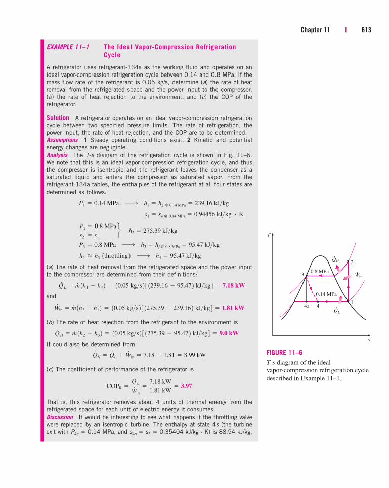
Analysis The T-s diagram of the refrigeration cycle is shown in Fig. 11–6.
We note that this is an ideal vapor-compression refrigeration cycle, and thus
the compressor is isentropic and the refrigerant leaves the condenser as a
saturated liquid and enters the compressor as saturated vapor. From the
refrigerant-134a tables, the enthalpies of the refrigerant at all four states are
determined as follows:
(a) The rate of heat removal from the refrigerated space and the power input
to the compressor are determined from their definitions:
and
(b) The rate of heat rejection from the refrigerant to the environment is
It could also be determined from
(c) The coefficient of performance of the refrigerator is
That is, this refrigerator removes about 4 units of thermal energy from the
refrigerated space for each unit of electric energy it consumes.
Discussion It would be interesting to see what happens if the throttling valve
were replaced by an isentropic turbine. The enthalpy at state 4s (the turbine
exit with P4s� 0.14 MPa, and s4s
� s3 � 0.35404 kJ/kg · K) is 88.94 kJ/kg,
COPR �Q#
L
W#
in
�7.18 kW
1.81 kW� 3.97
Q#
H � Q#
L � W#
in � 7.18 � 1.81 � 8.99 kW
Q#
H � m# 1h2 � h3 2 � 10.05 kg>s 2 3 1275.39 � 95.47 2 kJ>kg 4 � 9.0 kW
W#
in � m# 1h2 � h1 2 � 10.05 kg>s 2 3 1275.39 � 239.16 2 kJ>kg 4 � 1.81 kW
Q#
L � m# 1h1 � h4 2 � 10.05 kg>s 2 3 1239.16 � 95.47 2 kJ>kg 4 � 7.18 kW
h4 � h3 1throttling 2 ¡ h4 � 95.47 kJ>kg
P3 � 0.8 MPa ¡ h3 � hf @ 0.8 MPa � 95.47 kJ>kg
P2 � 0.8 MPa
s2 � s1
fÉh2 � 275.39 kJ>kg
s1 � sg @ 0.14 MPa � 0.94456 kJ>kg # K
P1 � 0.14 MPa ¡ h1 � hg @ 0.14 MPa � 239.16 kJ>kg
T
s
QH
41
4s
3
2
0.14 MPa
0.8 MPaWin
QL
FIGURE 11–6
T-s diagram of the ideal
vapor-compression refrigeration cycle
described in Example 11–1.
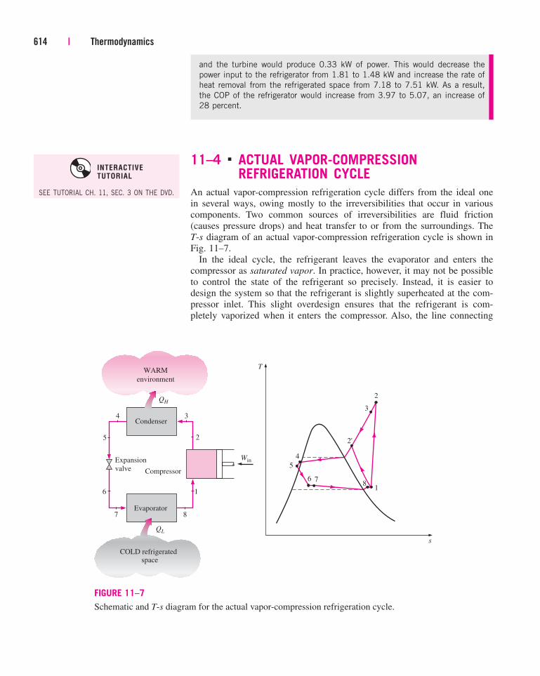
11–4 ■ ACTUAL VAPOR-COMPRESSIONREFRIGERATION CYCLE
An actual vapor-compression refrigeration cycle differs from the ideal one
in several ways, owing mostly to the irreversibilities that occur in various
components. Two common sources of irreversibilities are fluid friction
(causes pressure drops) and heat transfer to or from the surroundings. The
T-s diagram of an actual vapor-compression refrigeration cycle is shown in
Fig. 11–7.
In the ideal cycle, the refrigerant leaves the evaporator and enters the
compressor as saturated vapor. In practice, however, it may not be possible
to control the state of the refrigerant so precisely. Instead, it is easier to
design the system so that the refrigerant is slightly superheated at the com-
pressor inlet. This slight overdesign ensures that the refrigerant is com-
pletely vaporized when it enters the compressor. Also, the line connecting
614 | Thermodynamics
and the turbine would produce 0.33 kW of power. This would decrease the
power input to the refrigerator from 1.81 to 1.48 kW and increase the rate of
heat removal from the refrigerated space from 7.18 to 7.51 kW. As a result,
the COP of the refrigerator would increase from 3.97 to 5.07, an increase of
28 percent.
4
5
2
1
T
s
6 78
3
2'
4 3
7 8
Compressor
QH
2
Condenser
WARM
environment
QL
Evaporator
1
COLD refrigeratedspace
WinExpansion
valve
6
5
FIGURE 11–7
Schematic and T-s diagram for the actual vapor-compression refrigeration cycle.
SEE TUTORIAL CH. 11, SEC. 3 ON THE DVD.
INTERACTIVE
TUTORIAL
the evaporator to the compressor is usually very long; thus the pressure drop
caused by fluid friction and heat transfer from the surroundings to the
refrigerant can be very significant. The result of superheating, heat gain in
the connecting line, and pressure drops in the evaporator and the connecting
line is an increase in the specific volume, thus an increase in the power
input requirements to the compressor since steady-flow work is proportional
to the specific volume.
The compression process in the ideal cycle is internally reversible and
adiabatic, and thus isentropic. The actual compression process, however,
involves frictional effects, which increase the entropy, and heat transfer,
which may increase or decrease the entropy, depending on the direction.
Therefore, the entropy of the refrigerant may increase (process 1-2) or
decrease (process 1-2�) during an actual compression process, depending on
which effects dominate. The compression process 1-2� may be even more
desirable than the isentropic compression process since the specific volume
of the refrigerant and thus the work input requirement are smaller in this
case. Therefore, the refrigerant should be cooled during the compression
process whenever it is practical and economical to do so.
In the ideal case, the refrigerant is assumed to leave the condenser as sat-
urated liquid at the compressor exit pressure. In reality, however, it is
unavoidable to have some pressure drop in the condenser as well as in the
lines connecting the condenser to the compressor and to the throttling valve.
Also, it is not easy to execute the condensation process with such precision
that the refrigerant is a saturated liquid at the end, and it is undesirable to
route the refrigerant to the throttling valve before the refrigerant is com-
pletely condensed. Therefore, the refrigerant is subcooled somewhat before
it enters the throttling valve. We do not mind this at all, however, since the
refrigerant in this case enters the evaporator with a lower enthalpy and thus
can absorb more heat from the refrigerated space. The throttling valve and
the evaporator are usually located very close to each other, so the pressure
drop in the connecting line is small.
Chapter 11 | 615
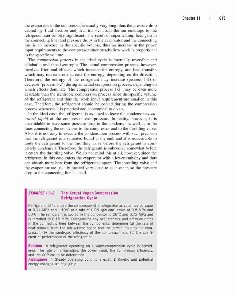
EXAMPLE 11–2 The Actual Vapor-Compression
Refrigeration Cycle
Refrigerant-134a enters the compressor of a refrigerator as superheated vapor
at 0.14 MPa and �10°C at a rate of 0.05 kg/s and leaves at 0.8 MPa and
50°C. The refrigerant is cooled in the condenser to 26°C and 0.72 MPa and
is throttled to 0.15 MPa. Disregarding any heat transfer and pressure drops
in the connecting lines between the components, determine (a) the rate of
heat removal from the refrigerated space and the power input to the com-
pressor, (b) the isentropic efficiency of the compressor, and (c) the coeffi-
cient of performance of the refrigerator.
Solution A refrigerator operating on a vapor-compression cycle is consid-
ered. The rate of refrigeration, the power input, the compressor efficiency,
and the COP are to be determined.
Assumptions 1 Steady operating conditions exist. 2 Kinetic and potential
energy changes are negligible.
11–5 ■ SELECTING THE RIGHT REFRIGERANT
When designing a refrigeration system, there are several refrigerants from
which to choose, such as chlorofluorocarbons (CFCs), ammonia, hydrocarbons
(propane, ethane, ethylene, etc.), carbon dioxide, air (in the air-conditioning of
aircraft), and even water (in applications above the freezing point). The right
616 | Thermodynamics
Analysis The T-s diagram of the refrigeration cycle is shown in Fig. 11–8.
We note that the refrigerant leaves the condenser as a compressed liquid
and enters the compressor as superheated vapor. The enthalpies of the
refrigerant at various states are determined from the refrigerant tables to be
h1 � 246.36 kJ/kg
h2 � 286.69 kJ/kg
h3 � h f @ 26°C � 87.83 kJ/kg
h4 � h3 (throttling) ⎯→ h4 � 87.83 kJ/kg
(a) The rate of heat removal from the refrigerated space and the power input
to the compressor are determined from their definitions:
and
(b) The isentropic efficiency of the compressor is determined from
where the enthalpy at state 2s (P2s� 0.8 MPa and s2s
� s1 � 0.9724
kJ/kg · K) is 284.21 kJ/kg. Thus,
(c) The coefficient of performance of the refrigerator is
Discussion This problem is identical to the one worked out in Example
11–1, except that the refrigerant is slightly superheated at the compressor
inlet and subcooled at the condenser exit. Also, the compressor is not isen-
tropic. As a result, the heat removal rate from the refrigerated space
increases (by 10.4 percent), but the power input to the compressor increases
even more (by 11.6 percent). Consequently, the COP of the refrigerator
decreases from 3.97 to 3.93.
COPR �Q#
L
W#
in
�7.93 kW
2.02 kW� 3.93
hC �284.21 � 246.36
286.69 � 246.36� 0.939 or 93.9%
hC �
h2s � h1
h2 � h1
W#
in � m# 1h2 � h1 2 � 10.05 kg>s 2 3 1286.69 � 246.36 2 kJ>kg 4 � 2.02 kW
Q#
L � m# 1h1 � h4 2 � 10.05 kg>s 2 3 1246.36 � 87.83 2 kJ>kg 4 � 7.93 kW
P3 �
T3 �
0.72 MPa26°C
f
P2 �
T2 �
0.8 MPa50°C
f
P1 �
T1 �
0.14 MPa�10°C
f
T
s
3
0.72 MPa26°C
4
QH
Win
QL
0.15 MPa
20.8 MPa50°C2s
10.14 MPa–10°C
FIGURE 11–8
T-s diagram for Example 11–2.
choice of refrigerant depends on the situation at hand. Of these, refrigerants
such as R-11, R-12, R-22, R-134a, and R-502 account for over 90 percent of
the market in the United States.
Ethyl ether was the first commercially used refrigerant in vapor-compression
systems in 1850, followed by ammonia, carbon dioxide, methyl chloride,
sulphur dioxide, butane, ethane, propane, isobutane, gasoline, and chlorofluo-
rocarbons, among others.
The industrial and heavy-commercial sectors were very satisfied with
ammonia, and still are, although ammonia is toxic. The advantages of
ammonia over other refrigerants are its low cost, higher COPs (and thus
lower energy cost), more favorable thermodynamic and transport properties
and thus higher heat transfer coefficients (requires smaller and lower-cost
heat exchangers), greater detectability in the event of a leak, and no effect
on the ozone layer. The major drawback of ammonia is its toxicity, which
makes it unsuitable for domestic use. Ammonia is predominantly used in
food refrigeration facilities such as the cooling of fresh fruits, vegetables,
meat, and fish; refrigeration of beverages and dairy products such as beer,
wine, milk, and cheese; freezing of ice cream and other foods; ice produc-
tion; and low-temperature refrigeration in the pharmaceutical and other
process industries.
It is remarkable that the early refrigerants used in the light-commercial and
household sectors such as sulfur dioxide, ethyl chloride, and methyl chloride
were highly toxic. The widespread publicity of a few instances of leaks that
resulted in serious illnesses and death in the 1920s caused a public cry to ban
or limit the use of these refrigerants, creating a need for the development of a
safe refrigerant for household use. At the request of Frigidaire Corporation,
General Motors’ research laboratory developed R-21, the first member of the
CFC family of refrigerants, within three days in 1928. Of several CFCs devel-
oped, the research team settled on R-12 as the refrigerant most suitable for
commercial use and gave the CFC family the trade name “Freon.” Commercial
production of R-11 and R-12 was started in 1931 by a company jointly formed
by General Motors and E. I. du Pont de Nemours and Co., Inc. The versatility
and low cost of CFCs made them the refrigerants of choice. CFCs were
also widely used in aerosols, foam insulations, and the electronic industry as
solvents to clean computer chips.
R-11 is used primarily in large-capacity water chillers serving air-
conditioning systems in buildings. R-12 is used in domestic refrigerators
and freezers, as well as automotive air conditioners. R-22 is used in window
air conditioners, heat pumps, air conditioners of commercial buildings, and
large industrial refrigeration systems, and offers strong competition to
ammonia. R-502 (a blend of R-115 and R-22) is the dominant refrigerant
used in commercial refrigeration systems such as those in supermarkets
because it allows low temperatures at evaporators while operating at single-
stage compression.
The ozone crisis has caused a major stir in the refrigeration and air-
conditioning industry and has triggered a critical look at the refrigerants in
use. It was realized in the mid-1970s that CFCs allow more ultraviolet radi-
ation into the earth’s atmosphere by destroying the protective ozone layer
and thus contributing to the greenhouse effect that causes global warming.
As a result, the use of some CFCs is banned by international treaties. Fully
Chapter 11 | 617
halogenated CFCs (such as R-11, R-12, and R-115) do the most damage to
the ozone layer. The nonfully halogenated refrigerants such as R-22 have
about 5 percent of the ozone-depleting capability of R-12. Refrigerants that
are friendly to the ozone layer that protects the earth from harmful ultraviolet
rays have been developed. The once popular refrigerant R-12 has largely
been replaced by the recently developed chlorine-free R-134a.
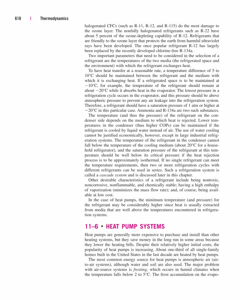
Two important parameters that need to be considered in the selection of a
refrigerant are the temperatures of the two media (the refrigerated space and
the environment) with which the refrigerant exchanges heat.
To have heat transfer at a reasonable rate, a temperature difference of 5 to
10°C should be maintained between the refrigerant and the medium with
which it is exchanging heat. If a refrigerated space is to be maintained at
�10°C, for example, the temperature of the refrigerant should remain at
about �20°C while it absorbs heat in the evaporator. The lowest pressure in a
refrigeration cycle occurs in the evaporator, and this pressure should be above
atmospheric pressure to prevent any air leakage into the refrigeration system.
Therefore, a refrigerant should have a saturation pressure of 1 atm or higher at
�20°C in this particular case. Ammonia and R-134a are two such substances.
The temperature (and thus the pressure) of the refrigerant on the con-
denser side depends on the medium to which heat is rejected. Lower tem-
peratures in the condenser (thus higher COPs) can be maintained if the
refrigerant is cooled by liquid water instead of air. The use of water cooling
cannot be justified economically, however, except in large industrial refrig-
eration systems. The temperature of the refrigerant in the condenser cannot
fall below the temperature of the cooling medium (about 20°C for a house-
hold refrigerator), and the saturation pressure of the refrigerant at this tem-
perature should be well below its critical pressure if the heat rejection
process is to be approximately isothermal. If no single refrigerant can meet
the temperature requirements, then two or more refrigeration cycles with
different refrigerants can be used in series. Such a refrigeration system is
called a cascade system and is discussed later in this chapter.
Other desirable characteristics of a refrigerant include being nontoxic,
noncorrosive, nonflammable, and chemically stable; having a high enthalpy
of vaporization (minimizes the mass flow rate); and, of course, being avail-
able at low cost.
In the case of heat pumps, the minimum temperature (and pressure) for
the refrigerant may be considerably higher since heat is usually extracted
from media that are well above the temperatures encountered in refrigera-
tion systems.
11–6 ■ HEAT PUMP SYSTEMS
Heat pumps are generally more expensive to purchase and install than other
heating systems, but they save money in the long run in some areas because
they lower the heating bills. Despite their relatively higher initial costs, the
popularity of heat pumps is increasing. About one-third of all single-family
homes built in the United States in the last decade are heated by heat pumps.
The most common energy source for heat pumps is atmospheric air (air-
to-air systems), although water and soil are also used. The major problem
with air-source systems is frosting, which occurs in humid climates when
the temperature falls below 2 to 5°C. The frost accumulation on the evapo-
618 | Thermodynamics
rator coils is highly undesirable since it seriously disrupts heat transfer. The
coils can be defrosted, however, by reversing the heat pump cycle (running
it as an air conditioner). This results in a reduction in the efficiency of the
system. Water-source systems usually use well water from depths of up to
80 m in the temperature range of 5 to 18°C, and they do not have a frosting
problem. They typically have higher COPs but are more complex and
require easy access to a large body of water such as underground water.
Ground-source systems are also rather involved since they require long tub-
ing placed deep in the ground where the soil temperature is relatively con-
stant. The COP of heat pumps usually ranges between 1.5 and 4, depending
on the particular system used and the temperature of the source. A new class
of recently developed heat pumps that use variable-speed electric motor
drives are at least twice as energy efficient as their predecessors.
Both the capacity and the efficiency of a heat pump fall significantly at
low temperatures. Therefore, most air-source heat pumps require a supple-
mentary heating system such as electric resistance heaters or an oil or gas
furnace. Since water and soil temperatures do not fluctuate much, supple-
mentary heating may not be required for water-source or ground-source sys-
tems. However, the heat pump system must be large enough to meet the
maximum heating load.
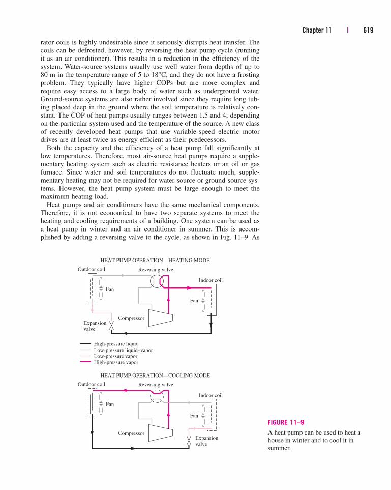
Heat pumps and air conditioners have the same mechanical components.
Therefore, it is not economical to have two separate systems to meet the
heating and cooling requirements of a building. One system can be used as
a heat pump in winter and an air conditioner in summer. This is accom-
plished by adding a reversing valve to the cycle, as shown in Fig. 11–9. As
Chapter 11 | 619
HEAT PUMP OPERATION—COOLING MODE
Outdoor coil Reversing valve
Indoor coil
Fan
Fan
CompressorExpansion
valve
HEAT PUMP OPERATION—HEATING MODE
Outdoor coil Reversing valve
Indoor coil
Fan
Fan
CompressorExpansionvalve
High-pressure liquid
Low-pressure liquid–vaporLow-pressure vapor
High-pressure vapor
FIGURE 11–9
A heat pump can be used to heat a
house in winter and to cool it in
summer.
a result of this modification, the condenser of the heat pump (located
indoors) functions as the evaporator of the air conditioner in summer. Also,
the evaporator of the heat pump (located outdoors) serves as the condenser
of the air conditioner. This feature increases the competitiveness of the heat
pump. Such dual-purpose units are commonly used in motels.
Heat pumps are most competitive in areas that have a large cooling load
during the cooling season and a relatively small heating load during the
heating season, such as in the southern parts of the United States. In these
areas, the heat pump can meet the entire cooling and heating needs of resi-
dential or commercial buildings. The heat pump is least competitive in areas
where the heating load is very large and the cooling load is small, such as in
the northern parts of the United States.
11–7 ■ INNOVATIVE VAPOR-COMPRESSIONREFRIGERATION SYSTEMS
The simple vapor-compression refrigeration cycle discussed above is the
most widely used refrigeration cycle, and it is adequate for most refrigera-
tion applications. The ordinary vapor-compression refrigeration systems are
simple, inexpensive, reliable, and practically maintenance-free (when was
the last time you serviced your household refrigerator?). However, for large
industrial applications efficiency, not simplicity, is the major concern. Also,
for some applications the simple vapor-compression refrigeration cycle is
inadequate and needs to be modified. We now discuss a few such modifica-
tions and refinements.
Cascade Refrigeration SystemsSome industrial applications require moderately low temperatures, and the
temperature range they involve may be too large for a single vapor-
compression refrigeration cycle to be practical. A large temperature range
also means a large pressure range in the cycle and a poor performance for a
reciprocating compressor. One way of dealing with such situations is to per-
form the refrigeration process in stages, that is, to have two or more refrig-
eration cycles that operate in series. Such refrigeration cycles are called
cascade refrigeration cycles.
A two-stage cascade refrigeration cycle is shown in Fig. 11–10. The two
cycles are connected through the heat exchanger in the middle, which serves
as the evaporator for the topping cycle (cycle A) and the condenser for the
bottoming cycle (cycle B). Assuming the heat exchanger is well insulated
and the kinetic and potential energies are negligible, the heat transfer from
the fluid in the bottoming cycle should be equal to the heat transfer to the
fluid in the topping cycle. Thus, the ratio of mass flow rates through each
cycle should be
(11–9)
Also,
(11–10)COPR,cascade �Q#
L
W#
net,in
�m#
B 1h1 � h4 2m#
A 1h6 � h5 2 � m#
B 1h2 � h1 2
m#
A 1h5 � h8 2 � m#
B 1h2 � h3 2 ¡ m#
A
m#
B
�h2 � h3
h5 � h8
620 | Thermodynamics
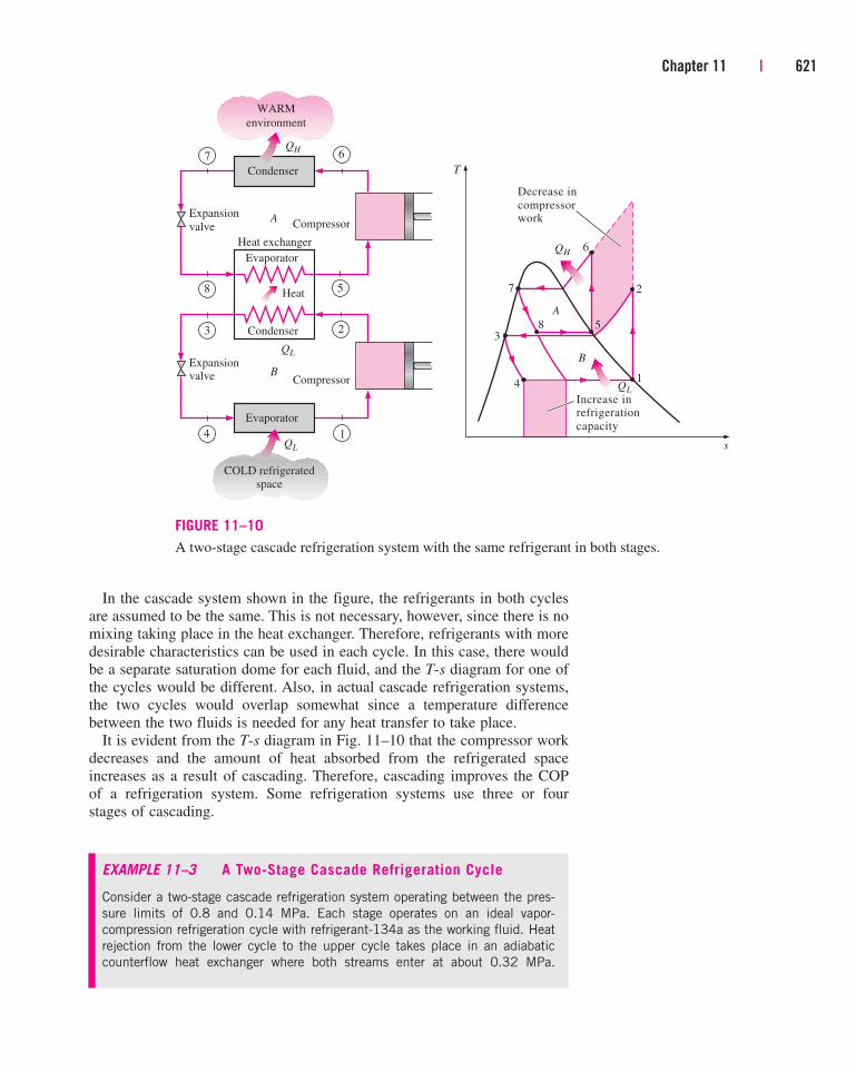
In the cascade system shown in the figure, the refrigerants in both cycles
are assumed to be the same. This is not necessary, however, since there is no
mixing taking place in the heat exchanger. Therefore, refrigerants with more
desirable characteristics can be used in each cycle. In this case, there would
be a separate saturation dome for each fluid, and the T-s diagram for one of
the cycles would be different. Also, in actual cascade refrigeration systems,
the two cycles would overlap somewhat since a temperature difference
between the two fluids is needed for any heat transfer to take place.
It is evident from the T-s diagram in Fig. 11–10 that the compressor work
decreases and the amount of heat absorbed from the refrigerated space
increases as a result of cascading. Therefore, cascading improves the COP
of a refrigeration system. Some refrigeration systems use three or four
stages of cascading.
Chapter 11 | 621
4
5
2
1
T
s
6
7
83
8 5
QH
Condenser
WARM
environment
QL
Evaporator
Decrease in
compressorwork
QH
QL
Increase inrefrigeration
capacity
Compressor
COLD refrigeratedspace
Expansion
valve
7 6
Compressor
Expansionvalve
3 2Condenser
Evaporator
A
B
QL
4
Heat exchanger
A
B
Heat
1
FIGURE 11–10
A two-stage cascade refrigeration system with the same refrigerant in both stages.
EXAMPLE 11–3 A Two-Stage Cascade Refrigeration Cycle
Consider a two-stage cascade refrigeration system operating between the pres-
sure limits of 0.8 and 0.14 MPa. Each stage operates on an ideal vapor-
compression refrigeration cycle with refrigerant-134a as the working fluid. Heat
rejection from the lower cycle to the upper cycle takes place in an adiabatic
counterflow heat exchanger where both streams enter at about 0.32 MPa.
622 | Thermodynamics
(In practice, the working fluid of the lower cycle is at a higher pressure and
temperature in the heat exchanger for effective heat transfer.) If the mass flow
rate of the refrigerant through the upper cycle is 0.05 kg/s, determine (a) the
mass flow rate of the refrigerant through the lower cycle, (b) the rate of heat
removal from the refrigerated space and the power input to the compressor,
and (c) the coefficient of performance of this cascade refrigerator.
Solution A cascade refrigeration system operating between the specified
pressure limits is considered. The mass flow rate of the refrigerant through
the lower cycle, the rate of refrigeration, the power input, and the COP are to
be determined.
Assumptions 1 Steady operating conditions exist. 2 Kinetic and potential
energy changes are negligible. 3 The heat exchanger is adiabatic.
Properties The enthalpies of the refrigerant at all eight states are deter-
mined from the refrigerant tables and are indicated on the T-s diagram.
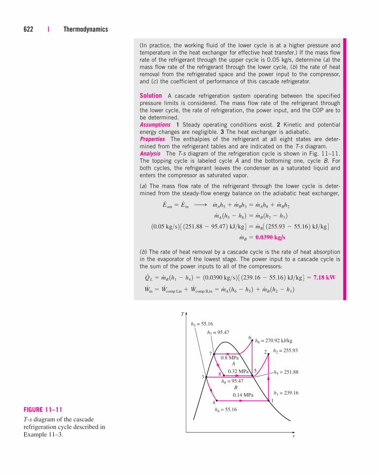
Analysis The T-s diagram of the refrigeration cycle is shown in Fig. 11–11.
The topping cycle is labeled cycle A and the bottoming one, cycle B. For
both cycles, the refrigerant leaves the condenser as a saturated liquid and
enters the compressor as saturated vapor.
(a) The mass flow rate of the refrigerant through the lower cycle is deter-
mined from the steady-flow energy balance on the adiabatic heat exchanger,
(b) The rate of heat removal by a cascade cycle is the rate of heat absorption
in the evaporator of the lowest stage. The power input to a cascade cycle is
the sum of the power inputs to all of the compressors:
W#
in � W#
comp I,in � W#
comp II,in � m#
A 1h6 � h5 2 � m#
B 1h2 � h1 2 Q#
L � m#
B 1h1 � h4 2 � 10.0390 kg>s 2 3 1239.16 � 55.16 2 kJ>kg 4 � 7.18 kW
m#
B � 0.0390 kg/s
10.05 kg>s 2 3 1251.88 � 95.47 2 kJ>kg 4 � m#
B 3 1255.93 � 55.16 2 kJ>kg 4 m#
A 1h5 � h8 2 � m#
B 1h2 � h3 2 E#
out � E#
in ¡ m#
Ah5 � m#
Bh3 � m#
Ah8 � m#
Bh2
4
3
2
1
T
s
6
7
85
h3 = 55.16
h7 = 95.47
h6 = 270.92 kJ/kg
h2 = 255.93
h5 = 251.88
h1 = 239.16
h4 = 55.16
h8 = 95.47
0.8 MPa
0.32 MPa
0.14 MPa
A
B
FIGURE 11–11
T-s diagram of the cascade
refrigeration cycle described in
Example 11–3.
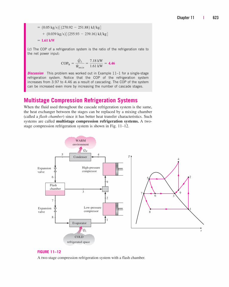
Multistage Compression Refrigeration SystemsWhen the fluid used throughout the cascade refrigeration system is the same,
the heat exchanger between the stages can be replaced by a mixing chamber
(called a flash chamber) since it has better heat transfer characteristics. Such
systems are called multistage compression refrigeration systems. A two-
stage compression refrigeration system is shown in Fig. 11–12.
Chapter 11 | 623
8
5 2
1
T
s
76 3
9
QH
Condenser
WARM
environment
High-pressurecompressor
COLD
refrigerated space
Expansion
valve
5 4
Expansionvalve
3
Evaporator
QL
4
9
2
1
6
7
8
Flashchamber
Low-pressurecompressor
FIGURE 11–12
A two-stage compression refrigeration system with a flash chamber.
(c) The COP of a refrigeration system is the ratio of the refrigeration rate to
the net power input:
Discussion This problem was worked out in Example 11–1 for a single-stage
refrigeration system. Notice that the COP of the refrigeration system
increases from 3.97 to 4.46 as a result of cascading. The COP of the system
can be increased even more by increasing the number of cascade stages.
COPR �Q#
L
W#
net,in
�7.18 kW
1.61 kW� 4.46
� 1.61 kW
� 10.039 kg>s 2 3 1255.93 � 239.16 2 kJ>kg 4 � 10.05 kg>s 2 3 1270.92 � 251.88 2 kJ>kg 4
624 | Thermodynamics
EXAMPLE 11–4 A Two-Stage Refrigeration Cycle
with a Flash Chamber
Consider a two-stage compression refrigeration system operating between the
pressure limits of 0.8 and 0.14 MPa. The working fluid is refrigerant-134a.
The refrigerant leaves the condenser as a saturated liquid and is throttled to
a flash chamber operating at 0.32 MPa. Part of the refrigerant evaporates
during this flashing process, and this vapor is mixed with the refrigerant
leaving the low-pressure compressor. The mixture is then compressed to the
condenser pressure by the high-pressure compressor. The liquid in the flash
chamber is throttled to the evaporator pressure and cools the refrigerated
space as it vaporizes in the evaporator. Assuming the refrigerant leaves the
evaporator as a saturated vapor and both compressors are isentropic, deter-
mine (a) the fraction of the refrigerant that evaporates as it is throttled to
the flash chamber, (b) the amount of heat removed from the refrigerated
space and the compressor work per unit mass of refrigerant flowing through
the condenser, and (c) the coefficient of performance.
Solution A two-stage compression refrigeration system operating between
specified pressure limits is considered. The fraction of the refrigerant that
evaporates in the flash chamber, the refrigeration and work input per unit
mass, and the COP are to be determined.
Assumptions 1 Steady operating conditions exist. 2 Kinetic and potential
energy changes are negligible. 3 The flash chamber is adiabatic.
Properties The enthalpies of the refrigerant at various states are determined
from the refrigerant tables and are indicated on the T-s diagram.
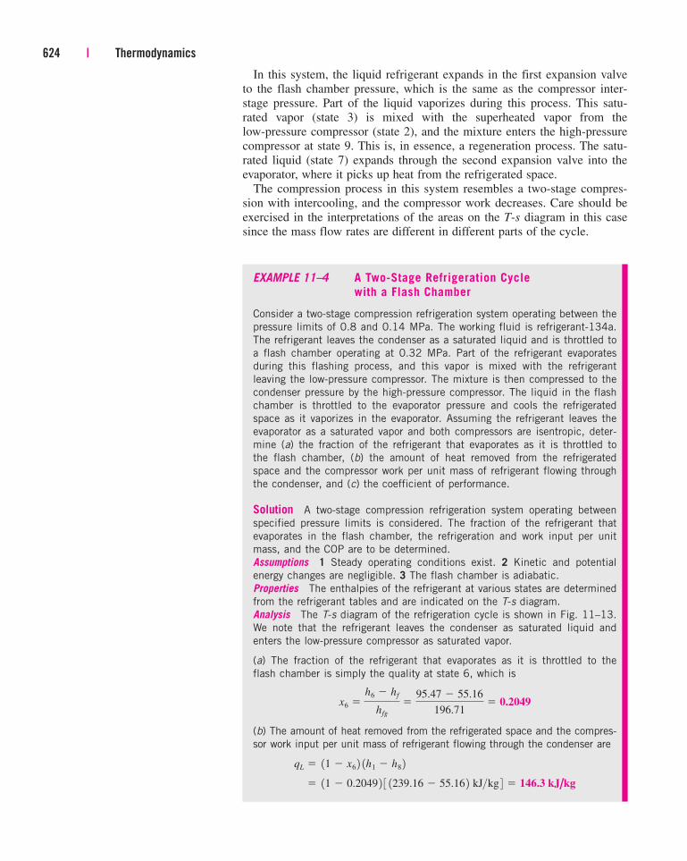
Analysis The T-s diagram of the refrigeration cycle is shown in Fig. 11–13.
We note that the refrigerant leaves the condenser as saturated liquid and
enters the low-pressure compressor as saturated vapor.
(a) The fraction of the refrigerant that evaporates as it is throttled to the
flash chamber is simply the quality at state 6, which is
(b) The amount of heat removed from the refrigerated space and the compres-
sor work input per unit mass of refrigerant flowing through the condenser are
� 11 � 0.2049 2 3 1239.16 � 55.16 2 kJ>kg 4 � 146.3 kJ/kg
qL � 11 � x6 2 1h1 � h8 2
x6 �
h6 � hf
hfg
�95.47 � 55.16
196.71� 0.2049
In this system, the liquid refrigerant expands in the first expansion valve
to the flash chamber pressure, which is the same as the compressor inter-
stage pressure. Part of the liquid vaporizes during this process. This satu-
rated vapor (state 3) is mixed with the superheated vapor from the
low-pressure compressor (state 2), and the mixture enters the high-pressure
compressor at state 9. This is, in essence, a regeneration process. The satu-
rated liquid (state 7) expands through the second expansion valve into the
evaporator, where it picks up heat from the refrigerated space.
The compression process in this system resembles a two-stage compres-
sion with intercooling, and the compressor work decreases. Care should be
exercised in the interpretations of the areas on the T-s diagram in this case
since the mass flow rates are different in different parts of the cycle.
Chapter 11 | 625
and
The enthalpy at state 9 is determined from an energy balance on the mixing
chamber,
Also, s9 � 0.9416 kJ/kg · K. Thus the enthalpy at state 4 (0.8 MPa, s4 �
s9) is h4 � 274.48 kJ/kg. Substituting,
(c) The coefficient of performance is
Discussion This problem was worked out in Example 11–1 for a single-stage
refrigeration system (COP � 3.97) and in Example 11–3 for a two-stage cas-
cade refrigeration system (COP � 4.46). Notice that the COP of the refriger-
ation system increased considerably relative to the single-stage compression
but did not change much relative to the two-stage cascade compression.
COPR �qL
win
�146.3 kJ>kg
32.71 kJ>kg� 4.47
� 32.71 kJ/kg
win � 11 � 0.2049 2 3 1255.93 � 239.16 2 kJ>kg 4 � 1274.48 � 255.10 2 kJ>kg
h9 � 10.2049 2 1251.88 2 � 11 � 0.2049 2 1255.93 2 � 255.10 kJ>kg
11 2h9 � x6h3 � 11 � x6 2h2
E#
out � E#
in
win � wcomp I,in � wcomp II,in � 11 � x6 2 1h2 � h1 2 � 11 2 1h4 � h9 2
8
7
2
1
T
s
4
5
6
9h7 = 55.16 h6 = 95.47
h4 = 274.48 kJ/kg
h2 = 255.93
h9 = 255.10
h1 = 239.16
h8 = 55.16
h3 = 251.883
h5 = 95.47
FIGURE 11–13
T-s diagram of the two-stage
compression refrigeration cycle
described in Example 11–4.
Multipurpose Refrigeration Systems with a Single CompressorSome applications require refrigeration at more than one temperature. This
could be accomplished by using a separate throttling valve and a separate
compressor for each evaporator operating at different temperatures. However,
such a system is bulky and probably uneconomical. A more practical and
economical approach would be to route all the exit streams from the evapora-
tors to a single compressor and let it handle the compression process for the
entire system.
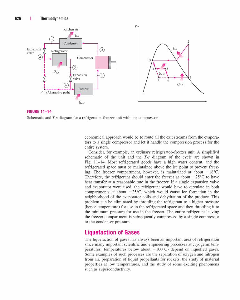
Consider, for example, an ordinary refrigerator–freezer unit. A simplified
schematic of the unit and the T-s diagram of the cycle are shown in
Fig. 11–14. Most refrigerated goods have a high water content, and the
refrigerated space must be maintained above the ice point to prevent freez-
ing. The freezer compartment, however, is maintained at about �18°C.
Therefore, the refrigerant should enter the freezer at about �25°C to have
heat transfer at a reasonable rate in the freezer. If a single expansion valve
and evaporator were used, the refrigerant would have to circulate in both
compartments at about �25°C, which would cause ice formation in the
neighborhood of the evaporator coils and dehydration of the produce. This
problem can be eliminated by throttling the refrigerant to a higher pressure
(hence temperature) for use in the refrigerated space and then throttling it to
the minimum pressure for use in the freezer. The entire refrigerant leaving
the freezer compartment is subsequently compressed by a single compressor
to the condenser pressure.
Liquefaction of GasesThe liquefaction of gases has always been an important area of refrigeration
since many important scientific and engineering processes at cryogenic tem-
peratures (temperatures below about �100°C) depend on liquefied gases.
Some examples of such processes are the separation of oxygen and nitrogen
from air, preparation of liquid propellants for rockets, the study of material
properties at low temperatures, and the study of some exciting phenomena
such as superconductivity.
626 | Thermodynamics
QH
QL,F
4
3
2
1
T
s
Compressor
QH
2
Kitchen air
Condenser
QL,F
Freezer
Expansion
valve
4
A 6
QL,R
5
Expansionvalve
QL,R
1
3
6
Refrigerator
(Alternative path)A
5
FIGURE 11–14
Schematic and T-s diagram for a refrigerator–freezer unit with one compressor.
At temperatures above the critical-point value, a substance exists in the
gas phase only. The critical temperatures of helium, hydrogen, and nitrogen
(three commonly used liquefied gases) are �268, �240, and �147°C,
respectively. Therefore, none of these substances exist in liquid form at
atmospheric conditions. Furthermore, low temperatures of this magnitude
cannot be obtained by ordinary refrigeration techniques. Then the question
that needs to be answered in the liquefaction of gases is this: How can we
lower the temperature of a gas below its critical-point value?
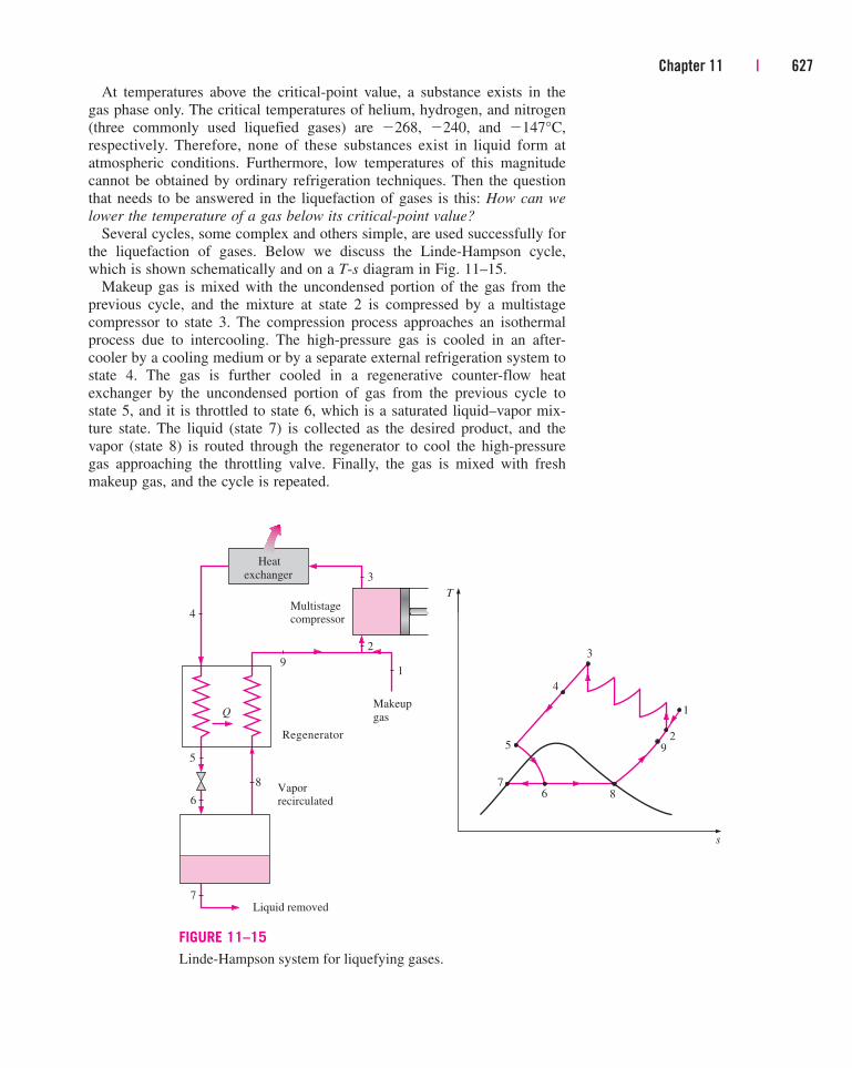
Several cycles, some complex and others simple, are used successfully for
the liquefaction of gases. Below we discuss the Linde-Hampson cycle,
which is shown schematically and on a T-s diagram in Fig. 11–15.
Makeup gas is mixed with the uncondensed portion of the gas from the
previous cycle, and the mixture at state 2 is compressed by a multistage
compressor to state 3. The compression process approaches an isothermal
process due to intercooling. The high-pressure gas is cooled in an after-
cooler by a cooling medium or by a separate external refrigeration system to
state 4. The gas is further cooled in a regenerative counter-flow heat
exchanger by the uncondensed portion of gas from the previous cycle to
state 5, and it is throttled to state 6, which is a saturated liquid–vapor mix-
ture state. The liquid (state 7) is collected as the desired product, and the
vapor (state 8) is routed through the regenerator to cool the high-pressure
gas approaching the throttling valve. Finally, the gas is mixed with fresh
makeup gas, and the cycle is repeated.
Chapter 11 | 627
4
52
1
T
s
78
3
Multistagecompressor
Q
6
9
4
6
5
8
7
Heat
exchanger 3
2
Liquid removed
Vaporrecirculated
Makeup
gas
Regenerator
1
9
FIGURE 11–15
Linde-Hampson system for liquefying gases.
This and other refrigeration cycles used for the liquefaction of gases can
also be used for the solidification of gases.
11–8 ■ GAS REFRIGERATION CYCLES
As explained in Sec. 11–2, the Carnot cycle (the standard of comparison for
power cycles) and the reversed Carnot cycle (the standard of comparison
for refrigeration cycles) are identical, except that the reversed Carnot cycle
operates in the reverse direction. This suggests that the power cycles dis-
cussed in earlier chapters can be used as refrigeration cycles by simply
reversing them. In fact, the vapor-compression refrigeration cycle is essen-
tially a modified Rankine cycle operating in reverse. Another example is the
reversed Stirling cycle, which is the cycle on which Stirling refrigerators
operate. In this section, we discuss the reversed Brayton cycle, better known
as the gas refrigeration cycle.
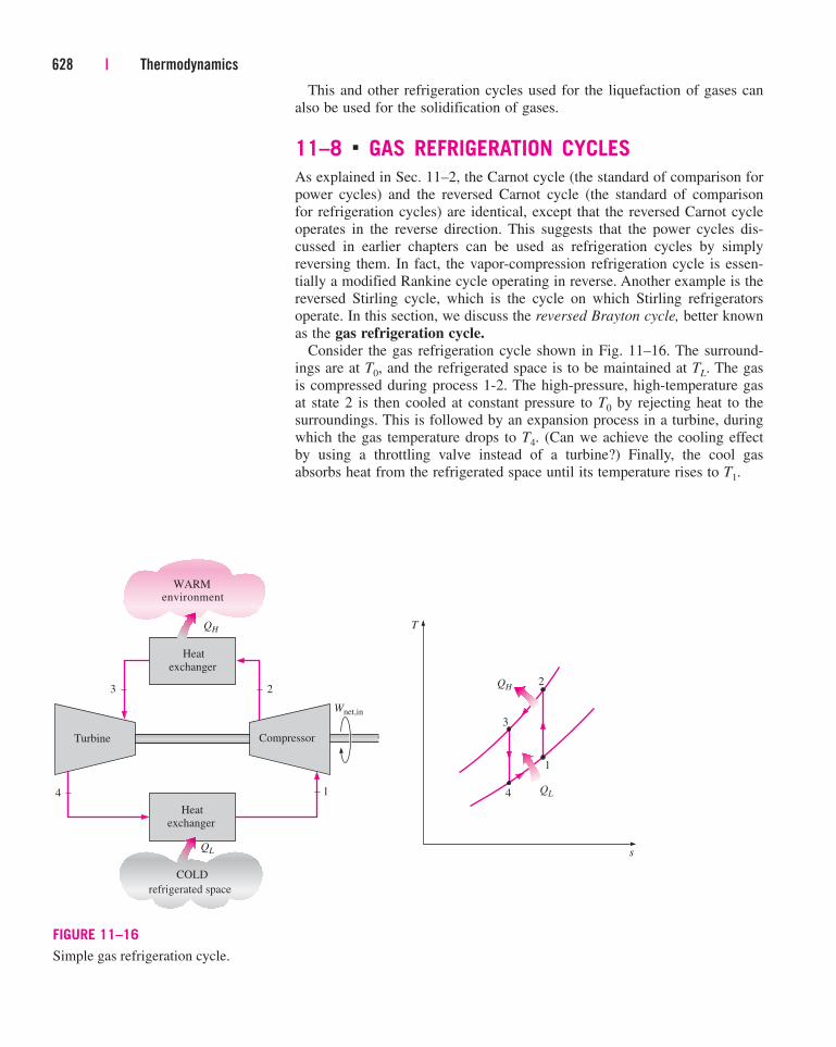
Consider the gas refrigeration cycle shown in Fig. 11–16. The surround-
ings are at T0, and the refrigerated space is to be maintained at TL. The gas
is compressed during process 1-2. The high-pressure, high-temperature gas
at state 2 is then cooled at constant pressure to T0 by rejecting heat to the
surroundings. This is followed by an expansion process in a turbine, during
which the gas temperature drops to T4. (Can we achieve the cooling effect
by using a throttling valve instead of a turbine?) Finally, the cool gas
absorbs heat from the refrigerated space until its temperature rises to T1.
628 | Thermodynamics
4
WARMenvironment
COLD
refrigerated space
QH
Heat
exchanger
QL
3
2
1
T
s
4
QH
QL
3 2
Compressor
Wnet,in
Heat
exchanger
Turbine
1
FIGURE 11–16
Simple gas refrigeration cycle.
All the processes described are internally reversible, and the cycle exe-
cuted is the ideal gas refrigeration cycle. In actual gas refrigeration cycles,
the compression and expansion processes deviate from the isentropic ones,
and T3 is higher than T0 unless the heat exchanger is infinitely large.
On a T-s diagram, the area under process curve 4-1 represents the heat
removed from the refrigerated space, and the enclosed area 1-2-3-4-1 repre-
sents the net work input. The ratio of these areas is the COP for the cycle,
which may be expressed as
(11–11)
where
The gas refrigeration cycle deviates from the reversed Carnot cycle
because the heat transfer processes are not isothermal. In fact, the gas tem-
perature varies considerably during heat transfer processes. Consequently, the
gas refrigeration cycles have lower COPs relative to the vapor-compression
refrigeration cycles or the reversed Carnot cycle. This is also evident from
the T-s diagram in Fig. 11–17. The reversed Carnot cycle consumes a frac-
tion of the net work (rectangular area 1A3B) but produces a greater amount
of refrigeration (triangular area under B1).
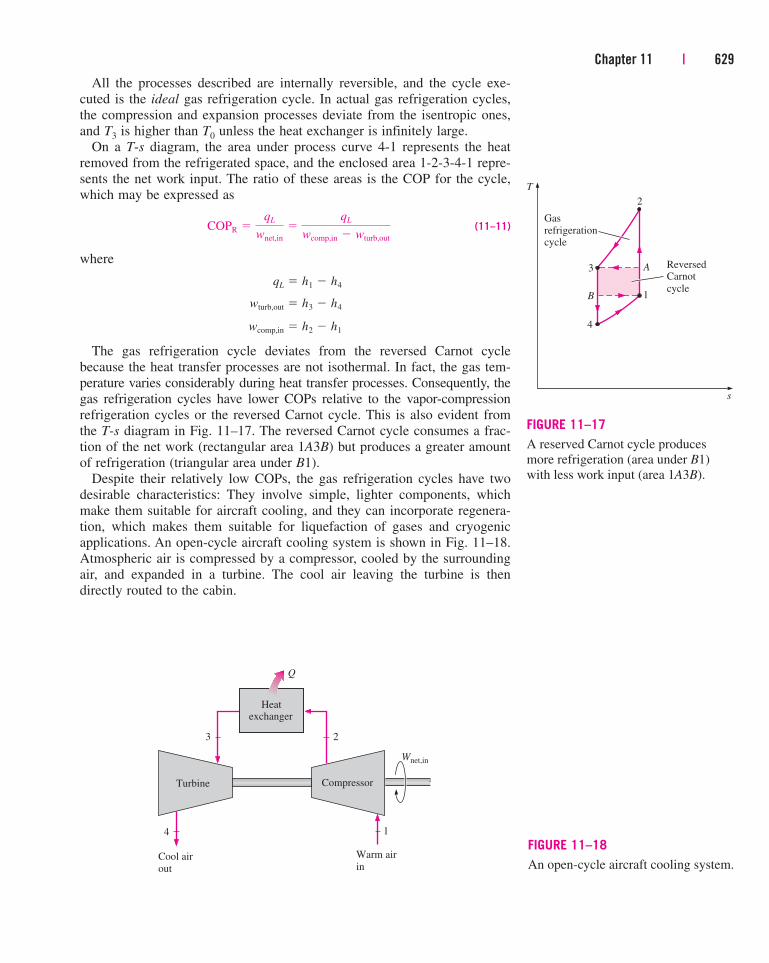
Despite their relatively low COPs, the gas refrigeration cycles have two
desirable characteristics: They involve simple, lighter components, which
make them suitable for aircraft cooling, and they can incorporate regenera-
tion, which makes them suitable for liquefaction of gases and cryogenic
applications. An open-cycle aircraft cooling system is shown in Fig. 11–18.
Atmospheric air is compressed by a compressor, cooled by the surrounding
air, and expanded in a turbine. The cool air leaving the turbine is then
directly routed to the cabin.
wcomp,in � h2 � h1
wturb,out � h3 � h4
qL � h1 � h4
COPR �qL
wnet,in
�qL
wcomp,in � wturb,out
Chapter 11 | 629
3
2
1
T
s
4
Gas
refrigerationcycle
A
B
ReversedCarnot
cycle
FIGURE 11–17
A reserved Carnot cycle produces
more refrigeration (area under B1)
with less work input (area 1A3B).
3
Compressor
Wnet,in
Heatexchanger
Cool air
out
Warm air
in
4
2
1
Turbine
Q
FIGURE 11–18
An open-cycle aircraft cooling system.
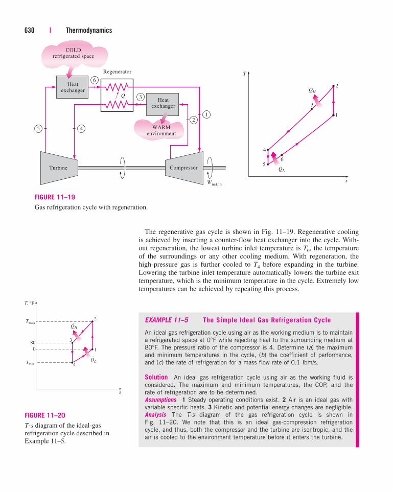
The regenerative gas cycle is shown in Fig. 11–19. Regenerative cooling
is achieved by inserting a counter-flow heat exchanger into the cycle. With-
out regeneration, the lowest turbine inlet temperature is T0, the temperature
of the surroundings or any other cooling medium. With regeneration, the
high-pressure gas is further cooled to T4 before expanding in the turbine.
Lowering the turbine inlet temperature automatically lowers the turbine exit
temperature, which is the minimum temperature in the cycle. Extremely low
temperatures can be achieved by repeating this process.
630 | Thermodynamics
1
45 WARMenvironment
Compressor
Wnet,in
Turbine
QHeat
exchanger
Heatexchanger
2
3
6
Regenerator
4
2
1
T
s
5
QH
QL
3
6
COLDrefrigerated space
FIGURE 11–19
Gas refrigeration cycle with regeneration.
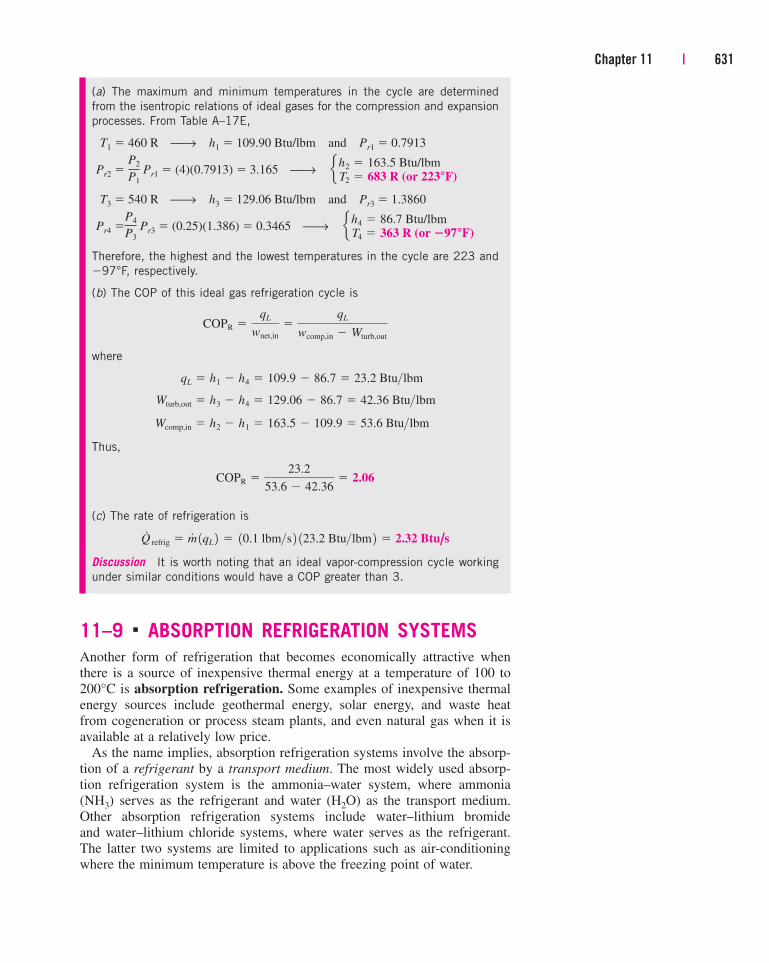
EXAMPLE 11–5 The Simple Ideal Gas Refrigeration Cycle
An ideal gas refrigeration cycle using air as the working medium is to maintain
a refrigerated space at 0°F while rejecting heat to the surrounding medium at
80°F. The pressure ratio of the compressor is 4. Determine (a) the maximum
and minimum temperatures in the cycle, (b) the coefficient of performance,
and (c) the rate of refrigeration for a mass flow rate of 0.1 lbm/s.
Solution An ideal gas refrigeration cycle using air as the working fluid is
considered. The maximum and minimum temperatures, the COP, and the
rate of refrigeration are to be determined.
Assumptions 1 Steady operating conditions exist. 2 Air is an ideal gas with
variable specific heats. 3 Kinetic and potential energy changes are negligible.
Analysis The T-s diagram of the gas refrigeration cycle is shown in
Fig. 11–20. We note that this is an ideal gas-compression refrigeration
cycle, and thus, both the compressor and the turbine are isentropic, and the
air is cooled to the environment temperature before it enters the turbine.
3
2
1
T, °F
s
4
QH
QL
Tmax
Tmin
80
0
·
·
FIGURE 11–20
T-s diagram of the ideal-gas
refrigeration cycle described in
Example 11–5.
11–9 ■ ABSORPTION REFRIGERATION SYSTEMS
Another form of refrigeration that becomes economically attractive when
there is a source of inexpensive thermal energy at a temperature of 100 to
200°C is absorption refrigeration. Some examples of inexpensive thermal
energy sources include geothermal energy, solar energy, and waste heat
from cogeneration or process steam plants, and even natural gas when it is
available at a relatively low price.
As the name implies, absorption refrigeration systems involve the absorp-
tion of a refrigerant by a transport medium. The most widely used absorp-
tion refrigeration system is the ammonia–water system, where ammonia
(NH3) serves as the refrigerant and water (H2O) as the transport medium.
Other absorption refrigeration systems include water–lithium bromide
and water–lithium chloride systems, where water serves as the refrigerant.
The latter two systems are limited to applications such as air-conditioning
where the minimum temperature is above the freezing point of water.
Chapter 11 | 631
(a) The maximum and minimum temperatures in the cycle are determined
from the isentropic relations of ideal gases for the compression and expansion
processes. From Table A–17E,
T1 � 460 R ⎯→ h1 � 109.90 Btu/lbm and Pr1 � 0.7913
Pr2 � Pr1 � (4)(0.7913) � 3.165 ⎯→
T3 � 540 R ⎯→ h3 � 129.06 Btu/lbm and Pr3 � 1.3860
Pr4 � Pr3 � (0.25)(1.386) � 0.3465 ⎯→
Therefore, the highest and the lowest temperatures in the cycle are 223 and
�97°F, respectively.
(b) The COP of this ideal gas refrigeration cycle is
where
Thus,
(c) The rate of refrigeration is
Discussion It is worth noting that an ideal vapor-compression cycle working
under similar conditions would have a COP greater than 3.
Q#
refrig � m# 1qL 2 � 10.1 lbm>s 2 123.2 Btu>lbm 2 � 2.32 Btu/s
COPR �23.2
53.6 � 42.36� 2.06
Wcomp,in � h2 � h1 � 163.5 � 109.9 � 53.6 Btu>lbm
Wturb,out � h3 � h4 � 129.06 � 86.7 � 42.36 Btu>lbm
qL � h1 � h4 � 109.9 � 86.7 � 23.2 Btu>lbm
COPR �qL
wnet,in
�qL
wcomp,in � Wturb,out
eh4 �
T4 �
86.7 Btu/lbm363 R (or �97°F)
P4
P3
eh2 �
T2 �
163.5 Btu/lbm683 R (or 223°F)
P2
P1
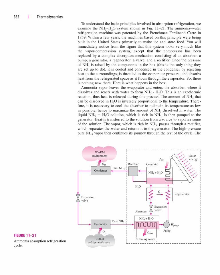
To understand the basic principles involved in absorption refrigeration, we
examine the NH3–H2O system shown in Fig. 11–21. The ammonia–water
refrigeration machine was patented by the Frenchman Ferdinand Carre in
1859. Within a few years, the machines based on this principle were being
built in the United States primarily to make ice and store food. You will
immediately notice from the figure that this system looks very much like
the vapor-compression system, except that the compressor has been
replaced by a complex absorption mechanism consisting of an absorber, a
pump, a generator, a regenerator, a valve, and a rectifier. Once the pressure
of NH3 is raised by the components in the box (this is the only thing they
are set up to do), it is cooled and condensed in the condenser by rejecting
heat to the surroundings, is throttled to the evaporator pressure, and absorbs
heat from the refrigerated space as it flows through the evaporator. So, there
is nothing new there. Here is what happens in the box:
Ammonia vapor leaves the evaporator and enters the absorber, where it
dissolves and reacts with water to form NH3 · H2O. This is an exothermic
reaction; thus heat is released during this process. The amount of NH3 that
can be dissolved in H2O is inversely proportional to the temperature. There-
fore, it is necessary to cool the absorber to maintain its temperature as low
as possible, hence to maximize the amount of NH3 dissolved in water. The
liquid NH3 � H2O solution, which is rich in NH3, is then pumped to the
generator. Heat is transferred to the solution from a source to vaporize some
of the solution. The vapor, which is rich in NH3, passes through a rectifier,
which separates the water and returns it to the generator. The high-pressure
pure NH3 vapor then continues its journey through the rest of the cycle. The
632 | Thermodynamics
QH
QL
Wpump
Qgen
Qcool
NH3 + H2O
WARM
environment
Expansionvalve
Expansion
valve
Pump
Cooling water
Condenser
Evaporator
COLD
refrigerated space
Pure NH3
Pure NH3
Rectifier Generator
H2O
Solarenergy
NH3 + H2O
Absorber
RegeneratorQ
FIGURE 11–21
Ammonia absorption refrigeration
cycle.
hot NH3 � H2O solution, which is weak in NH3, then passes through a
regenerator, where it transfers some heat to the rich solution leaving the
pump, and is throttled to the absorber pressure.
Compared with vapor-compression systems, absorption refrigeration sys-
tems have one major advantage: A liquid is compressed instead of a vapor.
The steady-flow work is proportional to the specific volume, and thus the
work input for absorption refrigeration systems is very small (on the order
of one percent of the heat supplied to the generator) and often neglected in
the cycle analysis. The operation of these systems is based on heat transfer
from an external source. Therefore, absorption refrigeration systems are
often classified as heat-driven systems.
The absorption refrigeration systems are much more expensive than the
vapor-compression refrigeration systems. They are more complex and
occupy more space, they are much less efficient thus requiring much larger
cooling towers to reject the waste heat, and they are more difficult to service
since they are less common. Therefore, absorption refrigeration systems
should be considered only when the unit cost of thermal energy is low and
is projected to remain low relative to electricity. Absorption refrigeration
systems are primarily used in large commercial and industrial installations.
The COP of absorption refrigeration systems is defined as
(11–12)
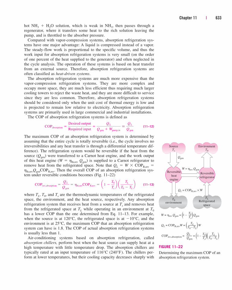
The maximum COP of an absorption refrigeration system is determined by
assuming that the entire cycle is totally reversible (i.e., the cycle involves no
irreversibilities and any heat transfer is through a differential temperature dif-
ference). The refrigeration system would be reversible if the heat from the
source (Qgen) were transferred to a Carnot heat engine, and the work output
of this heat engine (W � hth,rev Qgen) is supplied to a Carnot refrigerator to
remove heat from the refrigerated space. Note that QL � W � COPR,rev �
hth,revQgenCOPR,rev. Then the overall COP of an absorption refrigeration sys-
tem under reversible conditions becomes (Fig. 11–22)
(11–13)
where TL, T0, and Ts are the thermodynamic temperatures of the refrigerated
space, the environment, and the heat source, respectively. Any absorption
refrigeration system that receives heat from a source at Ts and removes heat
from the refrigerated space at TL while operating in an environment at T0
has a lower COP than the one determined from Eq. 11–13. For example,
when the source is at 120°C, the refrigerated space is at �10°C, and the
environment is at 25°C, the maximum COP that an absorption refrigeration
system can have is 1.8. The COP of actual absorption refrigeration systems
is usually less than 1.
Air-conditioning systems based on absorption refrigeration, called
absorption chillers, perform best when the heat source can supply heat at a
high temperature with little temperature drop. The absorption chillers are
typically rated at an input temperature of 116°C (240°F). The chillers per-
form at lower temperatures, but their cooling capacity decreases sharply with
COPrev,absorption �QL
Q gen
� hth,revCOPR,rev � a1 �T0
Ts
b a TL
T0 � TL
b
COPabsorption �Desired output
Required input�
QL
Q gen � Wpump,in
�
QL
Q gen
Chapter 11 | 633
SourceTs
T0environment
Reversible
heat
engine
Qgen
W = hrev Qgen
QL = COPR,rev × W
EnvironmentT0
TLRefrigerated
space
Reversible
refrigerator
W = hrev Qgen = (1 – )Qgen
QL = COPR,revW = ( )W
COPrev,absorption = = (1 – )( )
T0
Ts
TL
T0 – TL
Qgen
QL T0
Ts
TL
T0 – TL
FIGURE 11–22
Determining the maximum COP of an
absorption refrigeration system.
decreasing source temperature, about 12.5 percent for each 6°C (10°F) drop
in the source temperature. For example, the capacity goes down to 50 per-
cent when the supply water temperature drops to 93°C (200°F). In that case,
one needs to double the size (and thus the cost) of the chiller to achieve the
same cooling. The COP of the chiller is affected less by the decline of the
source temperature. The COP drops by 2.5 percent for each 6°C (10°F)
drop in the source temperature. The nominal COP of single-stage absorption
chillers at 116°C (240°F) is 0.65 to 0.70. Therefore, for each ton of refriger-
ation, a heat input of (12,000 Btu/h)/0.65 � 18,460 Btu/h is required.
At 88°C (190°F), the COP drops by 12.5 percent and thus the heat input
increases by 12.5 percent for the same cooling effect. Therefore, the eco-
nomic aspects must be evaluated carefully before any absorption refrigera-
tion system is considered, especially when the source temperature is below
93°C (200°F).
Another absorption refrigeration system that is quite popular with
campers is a propane-fired system invented by two Swedish undergraduate
students. In this system, the pump is replaced by a third fluid (hydrogen),
which makes it a truly portable unit.
634 | Thermodynamics
All the refrigeration systems discussed above involve many moving parts and
bulky, complex components. Then this question comes to mind: Is it really
necessary for a refrigeration system to be so complex? Can we not achieve
the same effect in a more direct way? The answer to this question is yes. It is
possible to use electric energy more directly to produce cooling without
involving any refrigerants and moving parts. Below we discuss one such sys-
tem, called thermoelectric refrigerator.
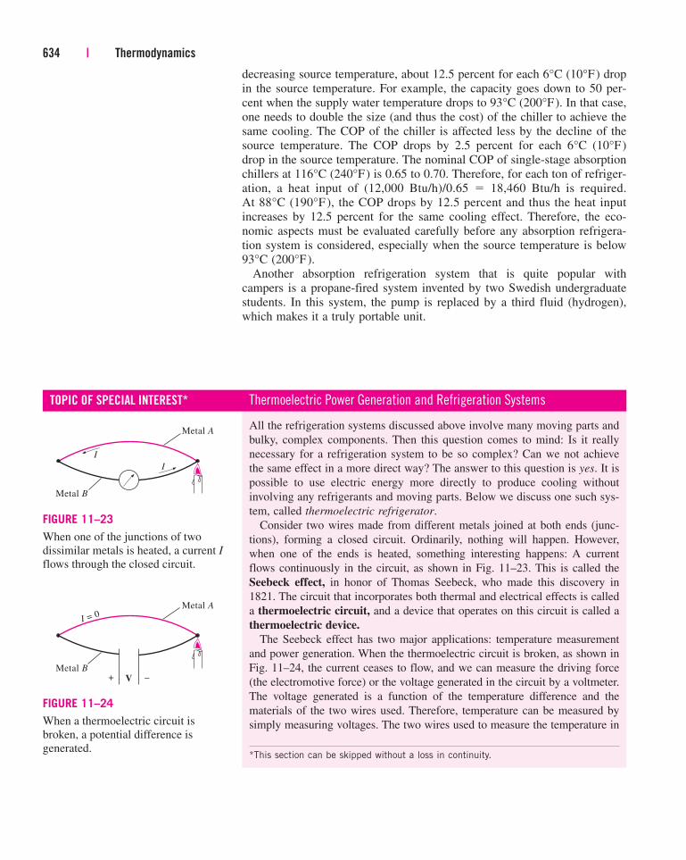
Consider two wires made from different metals joined at both ends (junc-
tions), forming a closed circuit. Ordinarily, nothing will happen. However,
when one of the ends is heated, something interesting happens: A current
flows continuously in the circuit, as shown in Fig. 11–23. This is called the
Seebeck effect, in honor of Thomas Seebeck, who made this discovery in
1821. The circuit that incorporates both thermal and electrical effects is called
a thermoelectric circuit, and a device that operates on this circuit is called a
thermoelectric device.
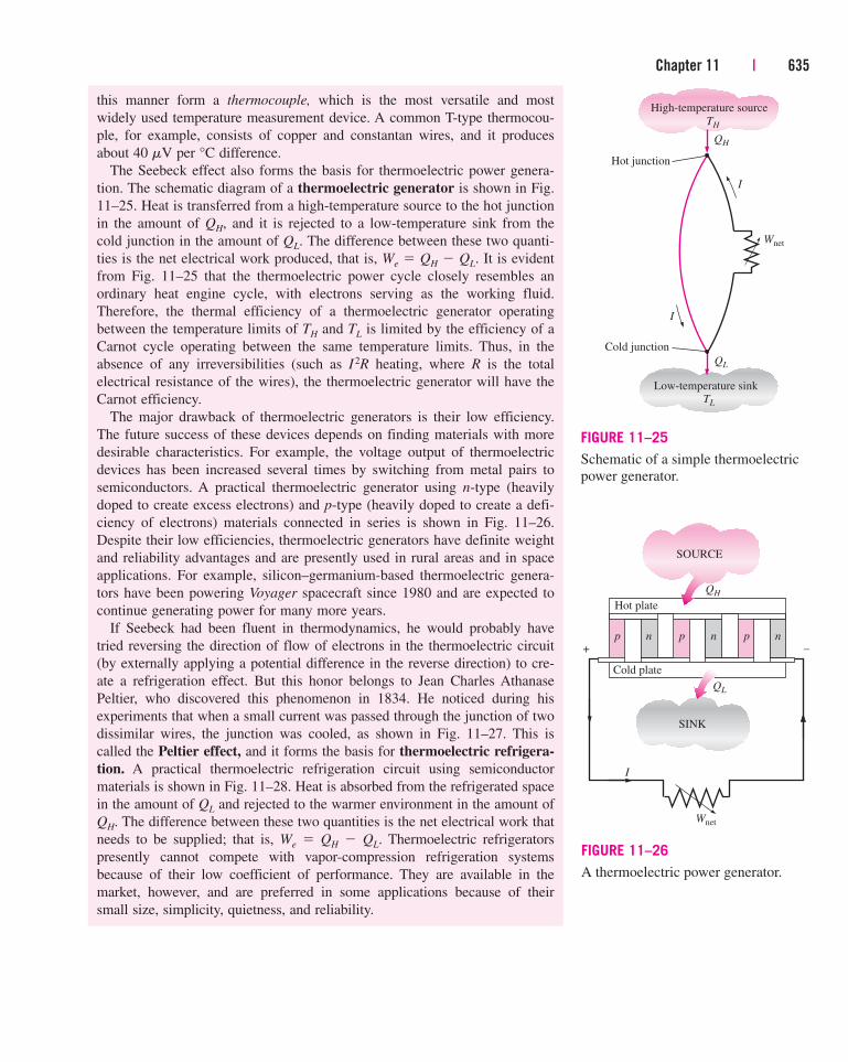
The Seebeck effect has two major applications: temperature measurement
and power generation. When the thermoelectric circuit is broken, as shown in
Fig. 11–24, the current ceases to flow, and we can measure the driving force
(the electromotive force) or the voltage generated in the circuit by a voltmeter.
The voltage generated is a function of the temperature difference and the
materials of the two wires used. Therefore, temperature can be measured by
simply measuring voltages. The two wires used to measure the temperature in
TOPIC OF SPECIAL INTEREST* Thermoelectric Power Generation and Refrigeration Systems
*This section can be skipped without a loss in continuity.
Metal A
Metal B
I
I
FIGURE 11–23
When one of the junctions of two
dissimilar metals is heated, a current I
flows through the closed circuit.
+ –
Metal A
Metal B
I = 0
V
FIGURE 11–24
When a thermoelectric circuit is
broken, a potential difference is
generated.
Chapter 11 | 635
this manner form a thermocouple, which is the most versatile and most
widely used temperature measurement device. A common T-type thermocou-
ple, for example, consists of copper and constantan wires, and it produces
about 40 mV per °C difference.
The Seebeck effect also forms the basis for thermoelectric power genera-
tion. The schematic diagram of a thermoelectric generator is shown in Fig.
11–25. Heat is transferred from a high-temperature source to the hot junction
in the amount of QH, and it is rejected to a low-temperature sink from the
cold junction in the amount of QL. The difference between these two quanti-
ties is the net electrical work produced, that is, We � QH � QL. It is evident
from Fig. 11–25 that the thermoelectric power cycle closely resembles an
ordinary heat engine cycle, with electrons serving as the working fluid.
Therefore, the thermal efficiency of a thermoelectric generator operating
between the temperature limits of TH and TL is limited by the efficiency of a
Carnot cycle operating between the same temperature limits. Thus, in the
absence of any irreversibilities (such as I2R heating, where R is the total
electrical resistance of the wires), the thermoelectric generator will have the
Carnot efficiency.
The major drawback of thermoelectric generators is their low efficiency.
The future success of these devices depends on finding materials with more
desirable characteristics. For example, the voltage output of thermoelectric
devices has been increased several times by switching from metal pairs to
semiconductors. A practical thermoelectric generator using n-type (heavily
doped to create excess electrons) and p-type (heavily doped to create a defi-
ciency of electrons) materials connected in series is shown in Fig. 11–26.
Despite their low efficiencies, thermoelectric generators have definite weight
and reliability advantages and are presently used in rural areas and in space
applications. For example, silicon–germanium-based thermoelectric genera-
tors have been powering Voyager spacecraft since 1980 and are expected to
continue generating power for many more years.
If Seebeck had been fluent in thermodynamics, he would probably have
tried reversing the direction of flow of electrons in the thermoelectric circuit
(by externally applying a potential difference in the reverse direction) to cre-
ate a refrigeration effect. But this honor belongs to Jean Charles Athanase
Peltier, who discovered this phenomenon in 1834. He noticed during his
experiments that when a small current was passed through the junction of two
dissimilar wires, the junction was cooled, as shown in Fig. 11–27. This is
called the Peltier effect, and it forms the basis for thermoelectric refrigera-
tion. A practical thermoelectric refrigeration circuit using semiconductor
materials is shown in Fig. 11–28. Heat is absorbed from the refrigerated space
in the amount of QL and rejected to the warmer environment in the amount of
QH. The difference between these two quantities is the net electrical work that
needs to be supplied; that is, We � QH � QL. Thermoelectric refrigerators
presently cannot compete with vapor-compression refrigeration systems
because of their low coefficient of performance. They are available in the
market, however, and are preferred in some applications because of their
small size, simplicity, quietness, and reliability.
Wnet
High-temperature source
TH
Low-temperature sinkTL
QH
QL
I
I
Hot junction
Cold junction
FIGURE 11–25
Schematic of a simple thermoelectric
power generator.
SOURCE
SINK
Hot plate
Cold plate
QH
QL
+ –
I
p n p n p n
Wnet
FIGURE 11–26
A thermoelectric power generator.
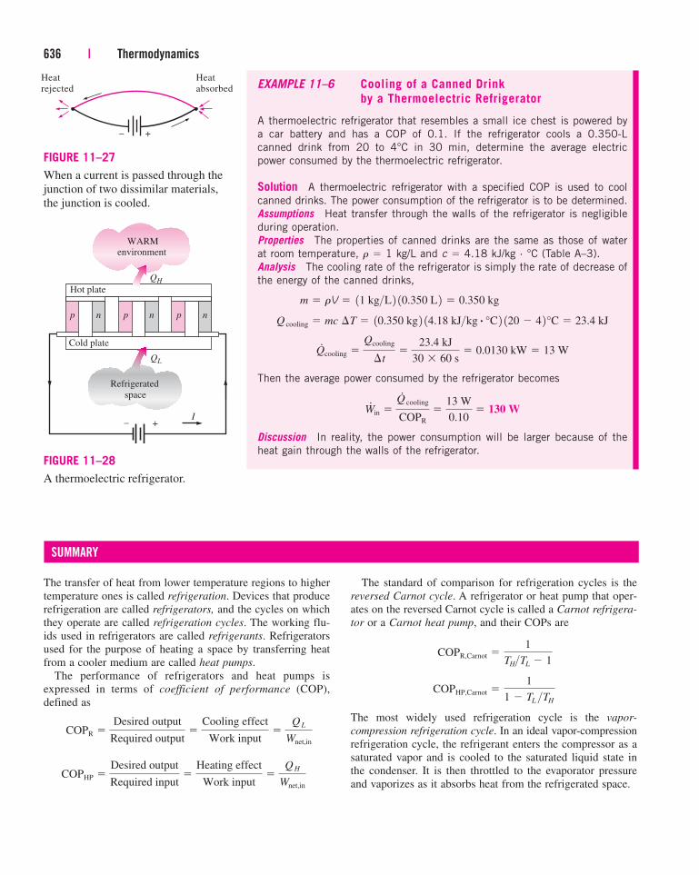
636 | Thermodynamics
EXAMPLE 11–6 Cooling of a Canned Drink
by a Thermoelectric Refrigerator
A thermoelectric refrigerator that resembles a small ice chest is powered by
a car battery and has a COP of 0.1. If the refrigerator cools a 0.350-L
canned drink from 20 to 4°C in 30 min, determine the average electric
power consumed by the thermoelectric refrigerator.
Solution A thermoelectric refrigerator with a specified COP is used to cool
canned drinks. The power consumption of the refrigerator is to be determined.
Assumptions Heat transfer through the walls of the refrigerator is negligible
during operation.
Properties The properties of canned drinks are the same as those of water
at room temperature, r � 1 kg/L and c � 4.18 kJ/kg · °C (Table A–3).
Analysis The cooling rate of the refrigerator is simply the rate of decrease of
the energy of the canned drinks,
Then the average power consumed by the refrigerator becomes
Discussion In reality, the power consumption will be larger because of the
heat gain through the walls of the refrigerator.
W#
in �
Q#
cooling
COPR
�13 W
0.10� 130 W
Q#
cooling �
Qcooling
¢t�
23.4 kJ
30 � 60 s� 0.0130 kW � 13 W
Q cooling � mc ¢T � 10.350 kg 2 14.18 kJ>kg # °C 2 120 � 4 2°C � 23.4 kJ
m � rV � 11 kg>L 2 10.350 L 2 � 0.350 kg
The transfer of heat from lower temperature regions to higher
temperature ones is called refrigeration. Devices that produce
refrigeration are called refrigerators, and the cycles on which
they operate are called refrigeration cycles. The working flu-
ids used in refrigerators are called refrigerants. Refrigerators
used for the purpose of heating a space by transferring heat
from a cooler medium are called heat pumps.
The performance of refrigerators and heat pumps is
expressed in terms of coefficient of performance (COP),
defined as
COPHP �Desired output
Required input�
Heating effect
Work input�
QH
Wnet,in
COPR �Desired output
Required output�
Cooling effect
Work input�
QL
Wnet,in
SUMMARY
The standard of comparison for refrigeration cycles is the
reversed Carnot cycle. A refrigerator or heat pump that oper-
ates on the reversed Carnot cycle is called a Carnot refrigera-
tor or a Carnot heat pump, and their COPs are
The most widely used refrigeration cycle is the vapor-
compression refrigeration cycle. In an ideal vapor-compression
refrigeration cycle, the refrigerant enters the compressor as a
saturated vapor and is cooled to the saturated liquid state in
the condenser. It is then throttled to the evaporator pressure
and vaporizes as it absorbs heat from the refrigerated space.
COPHP,Carnot �1
1 � TL >TH
COPR,Carnot �1
TH>TL � 1
+–
Heat
rejected
Heat
absorbed
FIGURE 11–27
When a current is passed through the
junction of two dissimilar materials,
the junction is cooled.
WARMenvironment
Refrigerated
space
Hot plate
Cold plate
QH
QL
+–I
p n p n p n
FIGURE 11–28
A thermoelectric refrigerator.
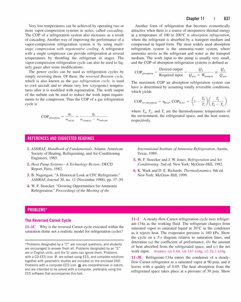
Chapter 11 | 637
Very low temperatures can be achieved by operating two or
more vapor-compression systems in series, called cascading.
The COP of a refrigeration system also increases as a result
of cascading. Another way of improving the performance of a
vapor-compression refrigeration system is by using multi-
stage compression with regenerative cooling. A refrigerator
with a single compressor can provide refrigeration at several
temperatures by throttling the refrigerant in stages. The
vapor-compression refrigeration cycle can also be used to liq-
uefy gases after some modifications.
The power cycles can be used as refrigeration cycles by
simply reversing them. Of these, the reversed Brayton cycle,
which is also known as the gas refrigeration cycle, is used
to cool aircraft and to obtain very low (cryogenic) tempera-
tures after it is modified with regeneration. The work output
of the turbine can be used to reduce the work input require-
ments to the compressor. Thus the COP of a gas refrigeration
cycle is
COPabsorption �qL
wnet,in
�qL
wcomp,in � wturb,out
Another form of refrigeration that becomes economically
attractive when there is a source of inexpensive thermal energy
at a temperature of 100 to 200°C is absorption refrigeration,
where the refrigerant is absorbed by a transport medium and
compressed in liquid form. The most widely used absorption
refrigeration system is the ammonia–water system, where
ammonia serves as the refrigerant and water as the transport
medium. The work input to the pump is usually very small,
and the COP of absorption refrigeration systems is defined as
The maximum COP an absorption refrigeration system can
have is determined by assuming totally reversible conditions,
which yields
where T0, TL, and Ts are the thermodynamic temperatures of
the environment, the refrigerated space, and the heat source,
respectively.
COPrev,absorption � hth,rev COPR,rev � a1 �T0
Ts
b a TL
T0 � TL
b
COPabsorption �
Desired output
Required input�
QL
Q gen � Wpump,in
�
QL
Q gen
1. ASHRAE, Handbook of Fundamentals. Atlanta: American
Society of Heating, Refrigerating, and Air-Conditioning
Engineers, 1985.
2. Heat Pump Systems—A Technology Review. OECD
Report, Paris, 1982.
3. B. Nagengast. “A Historical Look at CFC Refrigerants.”
ASHRAE Journal 30, no. 11 (November 1988), pp. 37–39.
4. W. F. Stoecker. “Growing Opportunities for Ammonia
Refrigeration.” Proceedings of the Meeting of the
REFERENCES AND SUGGESTED READINGS
International Institute of Ammonia Refrigeration, Austin,
Texas, 1989.
5. W. F. Stoecker and J. W. Jones. Refrigeration and Air
Conditioning. 2nd ed. New York: McGraw-Hill, 1982.
6. K. Wark and D. E. Richards. Thermodynamics. 6th ed.
New York: McGraw-Hill, 1999.
The Reversed Carnot Cycle
11–1C Why is the reversed Carnot cycle executed within the
saturation dome not a realistic model for refrigeration cycles?
PROBLEMS*
11–2 A steady-flow Carnot refrigeration cycle uses refriger-
ant-134a as the working fluid. The refrigerant changes from
saturated vapor to saturated liquid at 30°C in the condenser
as it rejects heat. The evaporator pressure is 160 kPa. Show
the cycle on a T-s diagram relative to saturation lines, and
determine (a) the coefficient of performance, (b) the amount
of heat absorbed from the refrigerated space, and (c) the net
work input. Answers: (a) 5.64, (b) 147 kJ/kg, (c) 26.1 kJ/kg
11–3E Refrigerant-134a enters the condenser of a steady-
flow Carnot refrigerator as a saturated vapor at 90 psia, and it
leaves with a quality of 0.05. The heat absorption from the
refrigerated space takes place at a pressure of 30 psia. Show
*Problems designated by a “C” are concept questions, and students
are encouraged to answer them all. Problems designated by an “E”
are in English units, and the SI users can ignore them. Problems
with a CD-EES icon are solved using EES, and complete solutions
together with parametric studies are included on the enclosed DVD.
Problems with a computer-EES icon are comprehensive in nature,
and are intended to be solved with a computer, preferably using the
EES software that accompanies this text.
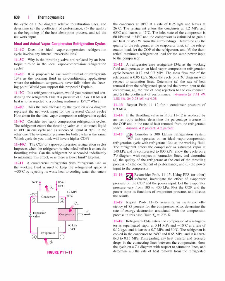
the cycle on a T-s diagram relative to saturation lines, and
determine (a) the coefficient of performance, (b) the quality
at the beginning of the heat-absorption process, and (c) the
net work input.
Ideal and Actual Vapor-Compression Refrigeration Cycles
11–4C Does the ideal vapor-compression refrigeration
cycle involve any internal irreversibilities?
11–5C Why is the throttling valve not replaced by an isen-
tropic turbine in the ideal vapor-compression refrigeration
cycle?
11–6C It is proposed to use water instead of refrigerant-
134a as the working fluid in air-conditioning applications
where the minimum temperature never falls below the freez-
ing point. Would you support this proposal? Explain.
11–7C In a refrigeration system, would you recommend con-
densing the refrigerant-134a at a pressure of 0.7 or 1.0 MPa if
heat is to be rejected to a cooling medium at 15°C? Why?
11–8C Does the area enclosed by the cycle on a T-s diagram
represent the net work input for the reversed Carnot cycle?
How about for the ideal vapor-compression refrigeration cycle?
11–9C Consider two vapor-compression refrigeration cycles.
The refrigerant enters the throttling valve as a saturated liquid
at 30°C in one cycle and as subcooled liquid at 30°C in the
other one. The evaporator pressure for both cycles is the same.
Which cycle do you think will have a higher COP?
11–10C The COP of vapor-compression refrigeration cycles
improves when the refrigerant is subcooled before it enters the
throttling valve. Can the refrigerant be subcooled indefinitely
to maximize this effect, or is there a lower limit? Explain.
11–11 A commercial refrigerator with refrigerant-134a as
the working fluid is used to keep the refrigerated space at
�30°C by rejecting its waste heat to cooling water that enters
638 | Thermodynamics
the condenser at 18°C at a rate of 0.25 kg/s and leaves at
26°C. The refrigerant enters the condenser at 1.2 MPa and
65°C and leaves at 42°C. The inlet state of the compressor is
60 kPa and �34°C and the compressor is estimated to gain a
net heat of 450 W from the surroundings. Determine (a) the
quality of the refrigerant at the evaporator inlet, (b) the refrig-
eration load, (c) the COP of the refrigerator, and (d) the theo-
retical maximum refrigeration load for the same power input
to the compressor.
11–12 A refrigerator uses refrigerant-134a as the working
fluid and operates on an ideal vapor-compression refrigeration
cycle between 0.12 and 0.7 MPa. The mass flow rate of the
refrigerant is 0.05 kg/s. Show the cycle on a T-s diagram with
respect to saturation lines. Determine (a) the rate of heat
removal from the refrigerated space and the power input to the
compressor, (b) the rate of heat rejection to the environment,
and (c) the coefficient of performance. Answers: (a) 7.41 kW,
1.83 kW, (b) 9.23 kW, (c) 4.06
11–13 Repeat Prob. 11–12 for a condenser pressure of
0.9 MPa.
11–14 If the throttling valve in Prob. 11–12 is replaced by
an isentropic turbine, determine the percentage increase in
the COP and in the rate of heat removal from the refrigerated
space. Answers: 4.2 percent, 4.2 percent
11–15 Consider a 300 kJ/min refrigeration system
that operates on an ideal vapor-compression
refrigeration cycle with refrigerant-134a as the working fluid.
The refrigerant enters the compressor as saturated vapor at
140 kPa and is compressed to 800 kPa. Show the cycle on a
T-s diagram with respect to saturation lines, and determine
(a) the quality of the refrigerant at the end of the throttling
process, (b) the coefficient of performance, and (c) the power
input to the compressor.
11–16 Reconsider Prob. 11–15. Using EES (or other)
software, investigate the effect of evaporator
pressure on the COP and the power input. Let the evaporator
pressure vary from 100 to 400 kPa. Plot the COP and the
power input as functions of evaporator pressure, and discuss
the results.
11–17 Repeat Prob. 11–15 assuming an isentropic effi-
ciency of 85 percent for the compressor. Also, determine the
rate of exergy destruction associated with the compression
process in this case. Take T0 � 298 K.
11–18 Refrigerant-134a enters the compressor of a refrigera-
tor as superheated vapor at 0.14 MPa and �10°C at a rate of
0.12 kg/s, and it leaves at 0.7 MPa and 50°C. The refrigerant is
cooled in the condenser to 24°C and 0.65 MPa, and it is throt-
tled to 0.15 MPa. Disregarding any heat transfer and pressure
drops in the connecting lines between the components, show
the cycle on a T-s diagram with respect to saturation lines, and
determine (a) the rate of heat removal from the refrigerated
Compressor
QH
Condenser
1.2 MPa
65°C
60 kPa
–34°C
Water
18°C
26°C
42°C
QL
Evaporator
Win
Qin
Expansion
valve
3
4 1
2
·
·
·
·
FIGURE P11–11
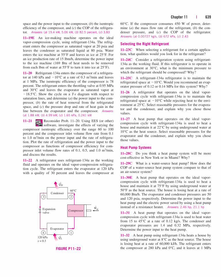
Chapter 11 | 639
space and the power input to the compressor, (b) the isentropic
efficiency of the compressor, and (c) the COP of the refrigera-
tor. Answers: (a) 19.4 kW, 5.06 kW, (b) 82.5 percent, (c) 3.83
11–19E An ice-making machine operates on the ideal
vapor-compression cycle, using refrigerant-134a. The refrig-
erant enters the compressor as saturated vapor at 20 psia and
leaves the condenser as saturated liquid at 80 psia. Water
enters the ice machine at 55°F and leaves as ice at 25°F. For
an ice production rate of 15 lbm/h, determine the power input
to the ice machine (169 Btu of heat needs to be removed
from each lbm of water at 55°F to turn it into ice at 25°F).
11–20 Refrigerant-134a enters the compressor of a refrigera-
tor at 140 kPa and �10°C at a rate of 0.3 m3/min and leaves
at 1 MPa. The isentropic efficiency of the compressor is 78
percent. The refrigerant enters the throttling valve at 0.95 MPa
and 30°C and leaves the evaporator as saturated vapor at
�18.5°C. Show the cycle on a T-s diagram with respect to
saturation lines, and determine (a) the power input to the com-
pressor, (b) the rate of heat removal from the refrigerated
space, and (c) the pressure drop and rate of heat gain in the
line between the evaporator and the compressor. Answers:
(a) 1.88 kW, (b) 4.99 kW, (c) 1.65 kPa, 0.241 kW
11–21 Reconsider Prob. 11–20. Using EES (or other)
software, investigate the effects of varying the
compressor isentropic efficiency over the range 60 to 100
percent and the compressor inlet volume flow rate from 0.1
to 1.0 m3/min on the power input and the rate of refrigera-
tion. Plot the rate of refrigeration and the power input to the
compressor as functions of compressor efficiency for com-
pressor inlet volume flow rates of 0.1, 0.5, and 1.0 m3/min,
and discuss the results.
11–22 A refrigerator uses refrigerant-134a as the working
fluid and operates on the ideal vapor-compression refrigera-
tion cycle. The refrigerant enters the evaporator at 120 kPa
with a quality of 30 percent and leaves the compressor at
60°C. If the compressor consumes 450 W of power, deter-
mine (a) the mass flow rate of the refrigerant, (b) the con-
denser pressure, and (c) the COP of the refrigerator.
Answers: (a) 0.00727 kg/s, (b) 672 kPa, (c) 2.43
Selecting the Right Refrigerant
11–23C When selecting a refrigerant for a certain applica-
tion, what qualities would you look for in the refrigerant?
11–24C Consider a refrigeration system using refrigerant-
134a as the working fluid. If this refrigerator is to operate in
an environment at 30°C, what is the minimum pressure to
which the refrigerant should be compressed? Why?
11–25C A refrigerant-134a refrigerator is to maintain the
refrigerated space at �10°C. Would you recommend an evap-
orator pressure of 0.12 or 0.14 MPa for this system? Why?
11–26 A refrigerator that operates on the ideal vapor-
compression cycle with refrigerant-134a is to maintain the
refrigerated space at �10°C while rejecting heat to the envi-
ronment at 25°C. Select reasonable pressures for the evapora-
tor and the condenser, and explain why you chose those
values.
11–27 A heat pump that operates on the ideal vapor-
compression cycle with refrigerant-134a is used to heat a
house and maintain it at 22°C by using underground water at
10°C as the heat source. Select reasonable pressures for the
evaporator and the condenser, and explain why you chose
those values.
Heat Pump Systems
11–28C Do you think a heat pump system will be more
cost-effective in New York or in Miami? Why?
11–29C What is a water-source heat pump? How does the
COP of a water-source heat pump system compare to that of
an air-source system?
11–30E A heat pump that operates on the ideal vapor-
compression cycle with refrigerant-134a is used to heat a
house and maintain it at 75°F by using underground water at
50°F as the heat source. The house is losing heat at a rate of
60,000 Btu/h. The evaporator and condenser pressures are 50
and 120 psia, respectively. Determine the power input to the
heat pump and the electric power saved by using a heat pump
instead of a resistance heater. Answers: 2.46 hp, 21.1 hp
11–31 A heat pump that operates on the ideal vapor-
compression cycle with refrigerant-134a is used to heat water
from 15 to 45°C at a rate of 0.12 kg/s. The condenser and
evaporator pressures are 1.4 and 0.32 MPa, respectively.
Determine the power input to the heat pump.
11–32 A heat pump using refrigerant-134a heats a house by
using underground water at 8°C as the heat source. The house
is losing heat at a rate of 60,000 kJ/h. The refrigerant enters
the compressor at 280 kPa and 0°C, and it leaves at 1 MPa
Compressor
QH
Condenser60°C
120 kPa
x = 0.3QL
Evaporator
WinExpansion
valve
3
4 1
2
·
·
·
FIGURE P11–22
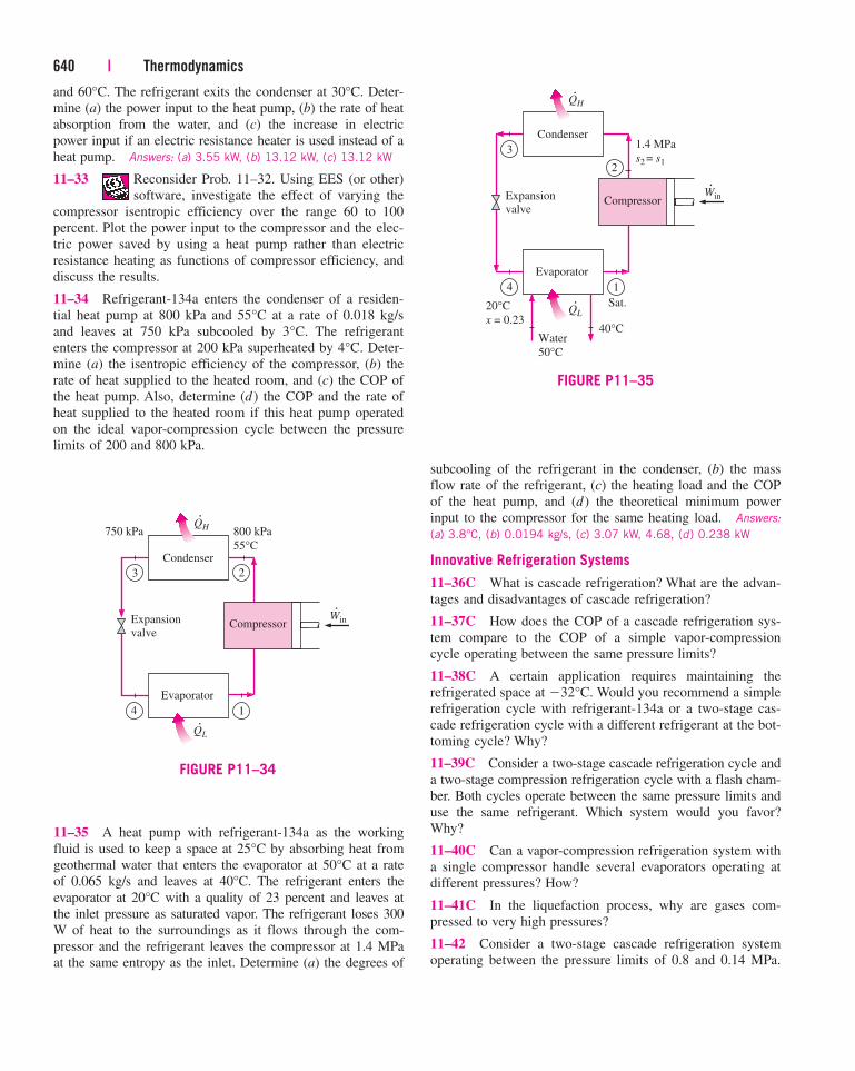
and 60°C. The refrigerant exits the condenser at 30°C. Deter-
mine (a) the power input to the heat pump, (b) the rate of heat
absorption from the water, and (c) the increase in electric
power input if an electric resistance heater is used instead of a
heat pump. Answers: (a) 3.55 kW, (b) 13.12 kW, (c) 13.12 kW
11–33 Reconsider Prob. 11–32. Using EES (or other)
software, investigate the effect of varying the
compressor isentropic efficiency over the range 60 to 100
percent. Plot the power input to the compressor and the elec-
tric power saved by using a heat pump rather than electric
resistance heating as functions of compressor efficiency, and
discuss the results.
11–34 Refrigerant-134a enters the condenser of a residen-
tial heat pump at 800 kPa and 55°C at a rate of 0.018 kg/s
and leaves at 750 kPa subcooled by 3°C. The refrigerant
enters the compressor at 200 kPa superheated by 4°C. Deter-
mine (a) the isentropic efficiency of the compressor, (b) the
rate of heat supplied to the heated room, and (c) the COP of
the heat pump. Also, determine (d ) the COP and the rate of
heat supplied to the heated room if this heat pump operated
on the ideal vapor-compression cycle between the pressure
limits of 200 and 800 kPa.
640 | Thermodynamics
subcooling of the refrigerant in the condenser, (b) the mass
flow rate of the refrigerant, (c) the heating load and the COP
of the heat pump, and (d) the theoretical minimum power
input to the compressor for the same heating load. Answers:
(a) 3.8°C, (b) 0.0194 kg/s, (c) 3.07 kW, 4.68, (d) 0.238 kW
Innovative Refrigeration Systems
11–36C What is cascade refrigeration? What are the advan-
tages and disadvantages of cascade refrigeration?
11–37C How does the COP of a cascade refrigeration sys-
tem compare to the COP of a simple vapor-compression
cycle operating between the same pressure limits?
11–38C A certain application requires maintaining the
refrigerated space at �32°C. Would you recommend a simple
refrigeration cycle with refrigerant-134a or a two-stage cas-
cade refrigeration cycle with a different refrigerant at the bot-
toming cycle? Why?
11–39C Consider a two-stage cascade refrigeration cycle and
a two-stage compression refrigeration cycle with a flash cham-
ber. Both cycles operate between the same pressure limits and
use the same refrigerant. Which system would you favor?
Why?
11–40C Can a vapor-compression refrigeration system with
a single compressor handle several evaporators operating at
different pressures? How?
11–41C In the liquefaction process, why are gases com-
pressed to very high pressures?
11–42 Consider a two-stage cascade refrigeration system
operating between the pressure limits of 0.8 and 0.14 MPa.
·
·
·
Compressor
QH
Condenser
750 kPa 800 kPa
55°C
QL
Evaporator
WinExpansion
valve
3
4 1
2
FIGURE P11–34
11–35 A heat pump with refrigerant-134a as the working
fluid is used to keep a space at 25°C by absorbing heat from
geothermal water that enters the evaporator at 50°C at a rate
of 0.065 kg/s and leaves at 40°C. The refrigerant enters the
evaporator at 20°C with a quality of 23 percent and leaves at
the inlet pressure as saturated vapor. The refrigerant loses 300
W of heat to the surroundings as it flows through the com-
pressor and the refrigerant leaves the compressor at 1.4 MPa
at the same entropy as the inlet. Determine (a) the degrees of
·
·
·
Compressor
QH
Condenser1.4 MPa
s2 = s1
20°C
x = 0.23
Sat.QL
Evaporator
WinExpansion
valve
3
4 1
2
Water
50°C
40°C
FIGURE P11–35
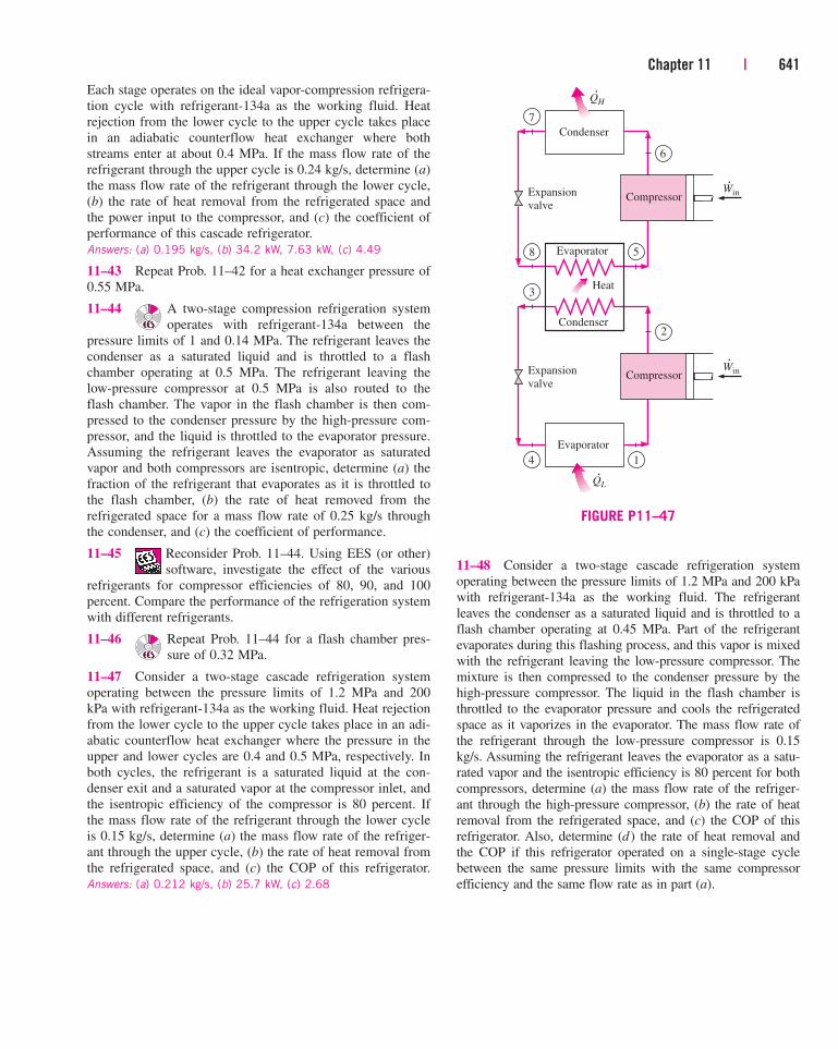
Chapter 11 | 641
Each stage operates on the ideal vapor-compression refrigera-
tion cycle with refrigerant-134a as the working fluid. Heat
rejection from the lower cycle to the upper cycle takes place
in an adiabatic counterflow heat exchanger where both
streams enter at about 0.4 MPa. If the mass flow rate of the
refrigerant through the upper cycle is 0.24 kg/s, determine (a)
the mass flow rate of the refrigerant through the lower cycle,
(b) the rate of heat removal from the refrigerated space and
the power input to the compressor, and (c) the coefficient of
performance of this cascade refrigerator.
Answers: (a) 0.195 kg/s, (b) 34.2 kW, 7.63 kW, (c) 4.49
11–43 Repeat Prob. 11–42 for a heat exchanger pressure of
0.55 MPa.
11–44 A two-stage compression refrigeration system
operates with refrigerant-134a between the
pressure limits of 1 and 0.14 MPa. The refrigerant leaves the
condenser as a saturated liquid and is throttled to a flash
chamber operating at 0.5 MPa. The refrigerant leaving the
low-pressure compressor at 0.5 MPa is also routed to the
flash chamber. The vapor in the flash chamber is then com-
pressed to the condenser pressure by the high-pressure com-
pressor, and the liquid is throttled to the evaporator pressure.
Assuming the refrigerant leaves the evaporator as saturated
vapor and both compressors are isentropic, determine (a) the
fraction of the refrigerant that evaporates as it is throttled to
the flash chamber, (b) the rate of heat removed from the
refrigerated space for a mass flow rate of 0.25 kg/s through
the condenser, and (c) the coefficient of performance.
11–45 Reconsider Prob. 11–44. Using EES (or other)
software, investigate the effect of the various
refrigerants for compressor efficiencies of 80, 90, and 100
percent. Compare the performance of the refrigeration system
with different refrigerants.
11–46 Repeat Prob. 11–44 for a flash chamber pres-
sure of 0.32 MPa.
11–47 Consider a two-stage cascade refrigeration system
operating between the pressure limits of 1.2 MPa and 200
kPa with refrigerant-134a as the working fluid. Heat rejection
from the lower cycle to the upper cycle takes place in an adi-
abatic counterflow heat exchanger where the pressure in the
upper and lower cycles are 0.4 and 0.5 MPa, respectively. In
both cycles, the refrigerant is a saturated liquid at the con-
denser exit and a saturated vapor at the compressor inlet, and
the isentropic efficiency of the compressor is 80 percent. If
the mass flow rate of the refrigerant through the lower cycle
is 0.15 kg/s, determine (a) the mass flow rate of the refriger-
ant through the upper cycle, (b) the rate of heat removal from
the refrigerated space, and (c) the COP of this refrigerator.
Answers: (a) 0.212 kg/s, (b) 25.7 kW, (c) 2.68
11–48 Consider a two-stage cascade refrigeration system
operating between the pressure limits of 1.2 MPa and 200 kPa
with refrigerant-134a as the working fluid. The refrigerant
leaves the condenser as a saturated liquid and is throttled to a
flash chamber operating at 0.45 MPa. Part of the refrigerant
evaporates during this flashing process, and this vapor is mixed
with the refrigerant leaving the low-pressure compressor. The
mixture is then compressed to the condenser pressure by the
high-pressure compressor. The liquid in the flash chamber is
throttled to the evaporator pressure and cools the refrigerated
space as it vaporizes in the evaporator. The mass flow rate of
the refrigerant through the low-pressure compressor is 0.15
kg/s. Assuming the refrigerant leaves the evaporator as a satu-
rated vapor and the isentropic efficiency is 80 percent for both
compressors, determine (a) the mass flow rate of the refriger-
ant through the high-pressure compressor, (b) the rate of heat
removal from the refrigerated space, and (c) the COP of this
refrigerator. Also, determine (d) the rate of heat removal and
the COP if this refrigerator operated on a single-stage cycle
between the same pressure limits with the same compressor
efficiency and the same flow rate as in part (a).
·
·
·
·
Compressor
QH
Condenser
WinExpansion
valve
7
8 5
6
Compressor
Evaporator
WinExpansion
valve
3
4 1
2
QL
Evaporator
Condenser
Heat
FIGURE P11–47
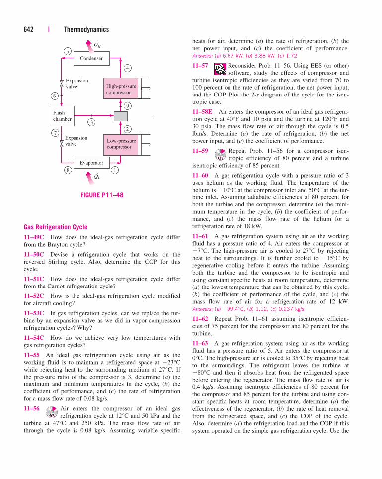
Gas Refrigeration Cycle
11–49C How does the ideal-gas refrigeration cycle differ
from the Brayton cycle?
11–50C Devise a refrigeration cycle that works on the
reversed Stirling cycle. Also, determine the COP for this
cycle.
11–51C How does the ideal-gas refrigeration cycle differ
from the Carnot refrigeration cycle?
11–52C How is the ideal-gas refrigeration cycle modified
for aircraft cooling?
11–53C In gas refrigeration cycles, can we replace the tur-
bine by an expansion valve as we did in vapor-compression
refrigeration cycles? Why?
11–54C How do we achieve very low temperatures with
gas refrigeration cycles?
11–55 An ideal gas refrigeration cycle using air as the
working fluid is to maintain a refrigerated space at �23°C
while rejecting heat to the surrounding medium at 27°C. If
the pressure ratio of the compressor is 3, determine (a) the
maximum and minimum temperatures in the cycle, (b) the
coefficient of performance, and (c) the rate of refrigeration
for a mass flow rate of 0.08 kg/s.
11–56 Air enters the compressor of an ideal gas
refrigeration cycle at 12°C and 50 kPa and the
turbine at 47°C and 250 kPa. The mass flow rate of air
through the cycle is 0.08 kg/s. Assuming variable specific
642 | Thermodynamics
heats for air, determine (a) the rate of refrigeration, (b) the
net power input, and (c) the coefficient of performance.
Answers: (a) 6.67 kW, (b) 3.88 kW, (c) 1.72
11–57 Reconsider Prob. 11–56. Using EES (or other)
software, study the effects of compressor and
turbine isentropic efficiencies as they are varied from 70 to
100 percent on the rate of refrigeration, the net power input,
and the COP. Plot the T-s diagram of the cycle for the isen-
tropic case.
11–58E Air enters the compressor of an ideal gas refrigera-
tion cycle at 40°F and 10 psia and the turbine at 120°F and
30 psia. The mass flow rate of air through the cycle is 0.5
lbm/s. Determine (a) the rate of refrigeration, (b) the net
power input, and (c) the coefficient of performance.
11–59 Repeat Prob. 11–56 for a compressor isen-
tropic efficiency of 80 percent and a turbine
isentropic efficiency of 85 percent.
11–60 A gas refrigeration cycle with a pressure ratio of 3
uses helium as the working fluid. The temperature of the
helium is �10°C at the compressor inlet and 50°C at the tur-
bine inlet. Assuming adiabatic efficiencies of 80 percent for
both the turbine and the compressor, determine (a) the mini-
mum temperature in the cycle, (b) the coefficient of perfor-
mance, and (c) the mass flow rate of the helium for a
refrigeration rate of 18 kW.
11–61 A gas refrigeration system using air as the working
fluid has a pressure ratio of 4. Air enters the compressor at
�7°C. The high-pressure air is cooled to 27°C by rejecting
heat to the surroundings. It is further cooled to �15°C by
regenerative cooling before it enters the turbine. Assuming
both the turbine and the compressor to be isentropic and
using constant specific heats at room temperature, determine
(a) the lowest temperature that can be obtained by this cycle,
(b) the coefficient of performance of the cycle, and (c) the
mass flow rate of air for a refrigeration rate of 12 kW.
Answers: (a) �99.4°C, (b) 1.12, (c) 0.237 kg/s
11–62 Repeat Prob. 11–61 assuming isentropic efficien-
cies of 75 percent for the compressor and 80 percent for the
turbine.
11–63 A gas refrigeration system using air as the working
fluid has a pressure ratio of 5. Air enters the compressor at
0°C. The high-pressure air is cooled to 35°C by rejecting heat
to the surroundings. The refrigerant leaves the turbine at
�80°C and then it absorbs heat from the refrigerated space
before entering the regenerator. The mass flow rate of air is
0.4 kg/s. Assuming isentropic efficiencies of 80 percent for
the compressor and 85 percent for the turbine and using con-
stant specific heats at room temperature, determine (a) the
effectiveness of the regenerator, (b) the rate of heat removal
from the refrigerated space, and (c) the COP of the cycle.
Also, determine (d) the refrigeration load and the COP if this
system operated on the simple gas refrigeration cycle. Use the
7
High-pressure
compressor
Low-pressurecompressor
QH
Condenser
Flash
chamber
Expansion
valve
Expansionvalve
5
6
9
2
3
8 1
4
Evaporator
QL
·
·
·
FIGURE P11–48
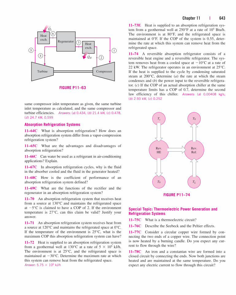
Chapter 11 | 643
same compressor inlet temperature as given, the same turbine
inlet temperature as calculated, and the same compressor and
turbine efficiencies. Answers: (a) 0.434, (b) 21.4 kW, (c) 0.478,
(d) 24.7 kW, 0.599
Absorption Refrigeration Systems
11–64C What is absorption refrigeration? How does an
absorption refrigeration system differ from a vapor-compression
refrigeration system?
11–65C What are the advantages and disadvantages of
absorption refrigeration?
11–66C Can water be used as a refrigerant in air-conditioning
applications? Explain.
11–67C In absorption refrigeration cycles, why is the fluid
in the absorber cooled and the fluid in the generator heated?
11–68C How is the coefficient of performance of an
absorption refrigeration system defined?
11–69C What are the functions of the rectifier and the
regenerator in an absorption refrigeration system?
11–70 An absorption refrigeration system that receives heat
from a source at 130°C and maintains the refrigerated space
at �5°C is claimed to have a COP of 2. If the environment
temperature is 27°C, can this claim be valid? Justify your
answer.
11–71 An absorption refrigeration system receives heat from
a source at 120°C and maintains the refrigerated space at 0°C.
If the temperature of the environment is 25°C, what is the
maximum COP this absorption refrigeration system can have?
11–72 Heat is supplied to an absorption refrigeration system
from a geothermal well at 130°C at a rate of 5 � 105 kJ/h.
The environment is at 25°C, and the refrigerated space is
maintained at �30°C. Determine the maximum rate at which
this system can remove heat from the refrigerated space.
Answer: 5.75 � 105 kJ/h
11–73E Heat is supplied to an absorption refrigeration sys-
tem from a geothermal well at 250°F at a rate of 105 Btu/h.
The environment is at 80°F, and the refrigerated space is
maintained at 0°F. If the COP of the system is 0.55, deter-
mine the rate at which this system can remove heat from the
refrigerated space.
11–74 A reversible absorption refrigerator consists of a
reversible heat engine and a reversible refrigerator. The sys-
tem removes heat from a cooled space at �10°C at a rate of
22 kW. The refrigerator operates in an environment at 25°C.
If the heat is supplied to the cycle by condensing saturated
steam at 200°C, determine (a) the rate at which the steam
condenses and (b) the power input to the reversible refrigera-
tor. (c) If the COP of an actual absorption chiller at the same
temperature limits has a COP of 0.7, determine the second
law efficiency of this chiller. Answers: (a) 0.00408 kg/s,
(b) 2.93 kW, (c) 0.252
Ts
Rev.
HE
T0
T0
Rev.
Ref.
TL
FIGURE P11–74
Heat
exch.
Heat
exch.
Regenerator
Turbine Compressor
1
6
3
5
4
QL
QH 2
·
·
FIGURE P11–63
Special Topic: Thermoelectric Power Generation andRefrigeration Systems
11–75C What is a thermoelectric circuit?
11–76C Describe the Seebeck and the Peltier effects.
11–77C Consider a circular copper wire formed by con-
necting the two ends of a copper wire. The connection point
is now heated by a burning candle. Do you expect any cur-
rent to flow through the wire?
11–78C An iron and a constantan wire are formed into a
closed circuit by connecting the ends. Now both junctions are
heated and are maintained at the same temperature. Do you
expect any electric current to flow through this circuit?
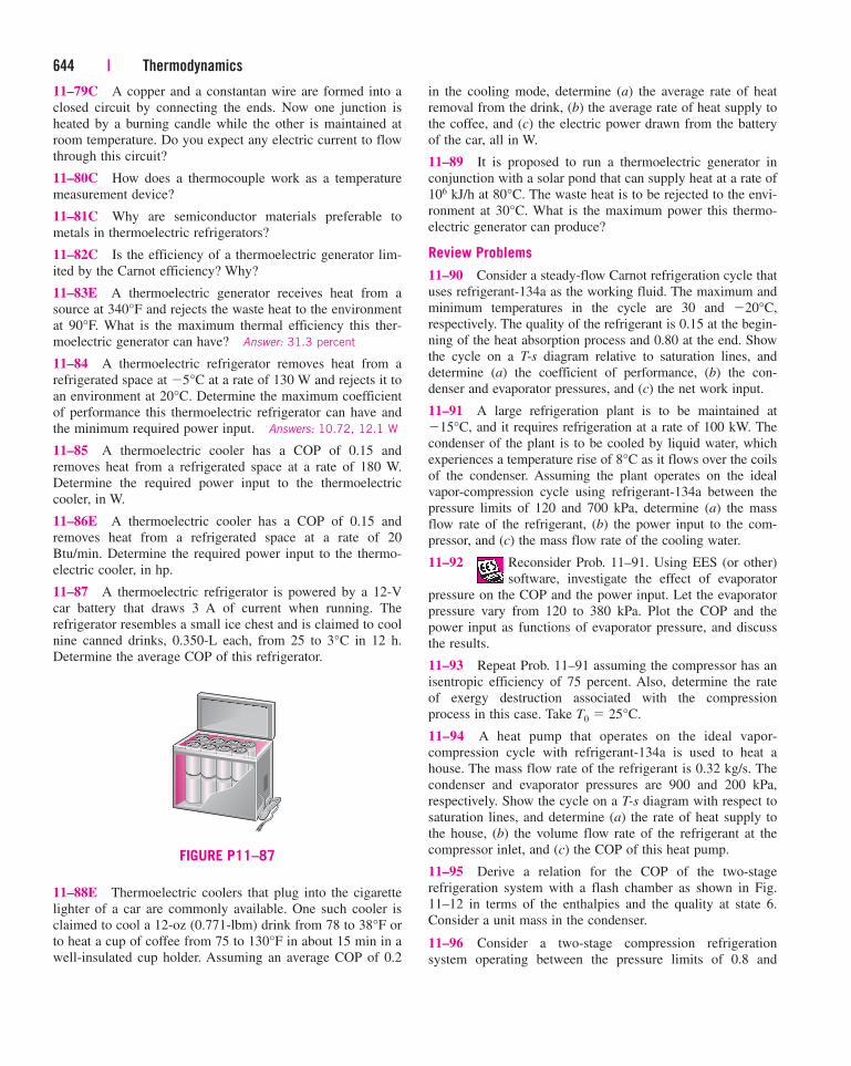
11–79C A copper and a constantan wire are formed into a
closed circuit by connecting the ends. Now one junction is
heated by a burning candle while the other is maintained at
room temperature. Do you expect any electric current to flow
through this circuit?
11–80C How does a thermocouple work as a temperature
measurement device?
11–81C Why are semiconductor materials preferable to
metals in thermoelectric refrigerators?
11–82C Is the efficiency of a thermoelectric generator lim-
ited by the Carnot efficiency? Why?
11–83E A thermoelectric generator receives heat from a
source at 340°F and rejects the waste heat to the environment
at 90°F. What is the maximum thermal efficiency this ther-
moelectric generator can have? Answer: 31.3 percent
11–84 A thermoelectric refrigerator removes heat from a
refrigerated space at �5°C at a rate of 130 W and rejects it to
an environment at 20°C. Determine the maximum coefficient
of performance this thermoelectric refrigerator can have and
the minimum required power input. Answers: 10.72, 12.1 W
11–85 A thermoelectric cooler has a COP of 0.15 and
removes heat from a refrigerated space at a rate of 180 W.
Determine the required power input to the thermoelectric
cooler, in W.
11–86E A thermoelectric cooler has a COP of 0.15 and
removes heat from a refrigerated space at a rate of 20
Btu/min. Determine the required power input to the thermo-
electric cooler, in hp.
11–87 A thermoelectric refrigerator is powered by a 12-V
car battery that draws 3 A of current when running. The
refrigerator resembles a small ice chest and is claimed to cool
nine canned drinks, 0.350-L each, from 25 to 3°C in 12 h.
Determine the average COP of this refrigerator.
644 | Thermodynamics
in the cooling mode, determine (a) the average rate of heat
removal from the drink, (b) the average rate of heat supply to
the coffee, and (c) the electric power drawn from the battery
of the car, all in W.
11–89 It is proposed to run a thermoelectric generator in
conjunction with a solar pond that can supply heat at a rate of
106 kJ/h at 80°C. The waste heat is to be rejected to the envi-
ronment at 30°C. What is the maximum power this thermo-
electric generator can produce?
Review Problems
11–90 Consider a steady-flow Carnot refrigeration cycle that
uses refrigerant-134a as the working fluid. The maximum and
minimum temperatures in the cycle are 30 and �20°C,
respectively. The quality of the refrigerant is 0.15 at the begin-
ning of the heat absorption process and 0.80 at the end. Show
the cycle on a T-s diagram relative to saturation lines, and
determine (a) the coefficient of performance, (b) the con-
denser and evaporator pressures, and (c) the net work input.
11–91 A large refrigeration plant is to be maintained at
�15°C, and it requires refrigeration at a rate of 100 kW. The
condenser of the plant is to be cooled by liquid water, which
experiences a temperature rise of 8°C as it flows over the coils
of the condenser. Assuming the plant operates on the ideal
vapor-compression cycle using refrigerant-134a between the
pressure limits of 120 and 700 kPa, determine (a) the mass
flow rate of the refrigerant, (b) the power input to the com-
pressor, and (c) the mass flow rate of the cooling water.
11–92 Reconsider Prob. 11–91. Using EES (or other)
software, investigate the effect of evaporator
pressure on the COP and the power input. Let the evaporator
pressure vary from 120 to 380 kPa. Plot the COP and the
power input as functions of evaporator pressure, and discuss
the results.
11–93 Repeat Prob. 11–91 assuming the compressor has an
isentropic efficiency of 75 percent. Also, determine the rate
of exergy destruction associated with the compression
process in this case. Take T0 � 25°C.
11–94 A heat pump that operates on the ideal vapor-
compression cycle with refrigerant-134a is used to heat a
house. The mass flow rate of the refrigerant is 0.32 kg/s. The
condenser and evaporator pressures are 900 and 200 kPa,
respectively. Show the cycle on a T-s diagram with respect to
saturation lines, and determine (a) the rate of heat supply to
the house, (b) the volume flow rate of the refrigerant at the
compressor inlet, and (c) the COP of this heat pump.
11–95 Derive a relation for the COP of the two-stage
refrigeration system with a flash chamber as shown in Fig.
11–12 in terms of the enthalpies and the quality at state 6.
Consider a unit mass in the condenser.
11–96 Consider a two-stage compression refrigeration
system operating between the pressure limits of 0.8 and
FIGURE P11–87
11–88E Thermoelectric coolers that plug into the cigarette
lighter of a car are commonly available. One such cooler is
claimed to cool a 12-oz (0.771-lbm) drink from 78 to 38°F or
to heat a cup of coffee from 75 to 130°F in about 15 min in a
well-insulated cup holder. Assuming an average COP of 0.2
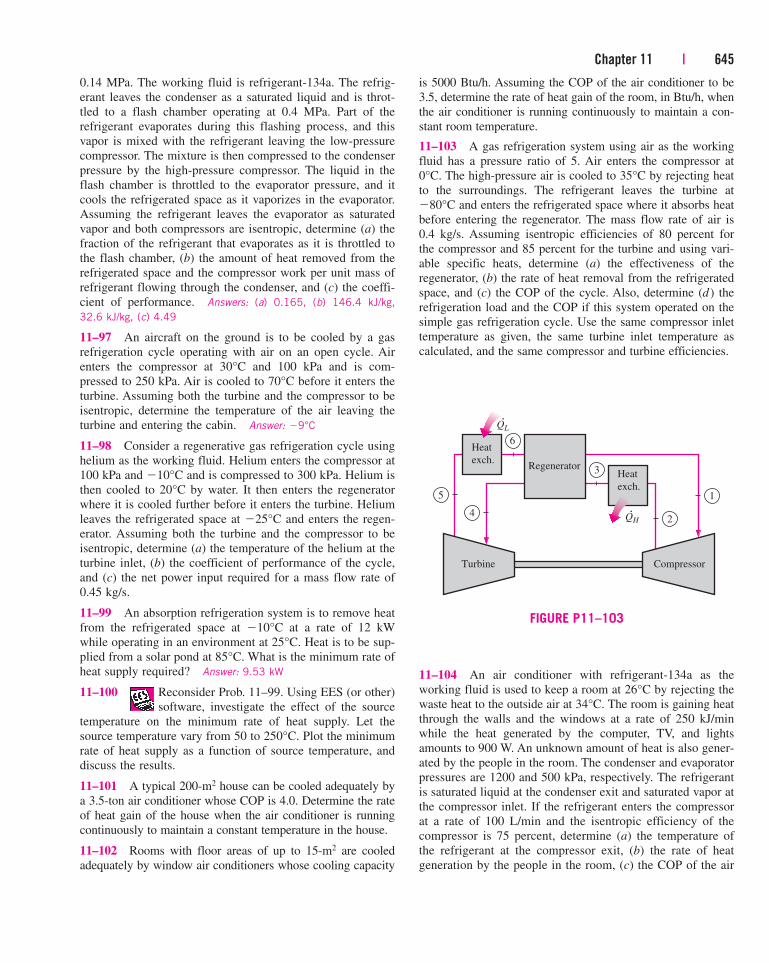
Chapter 11 | 645
0.14 MPa. The working fluid is refrigerant-134a. The refrig-
erant leaves the condenser as a saturated liquid and is throt-
tled to a flash chamber operating at 0.4 MPa. Part of the
refrigerant evaporates during this flashing process, and this
vapor is mixed with the refrigerant leaving the low-pressure
compressor. The mixture is then compressed to the condenser
pressure by the high-pressure compressor. The liquid in the
flash chamber is throttled to the evaporator pressure, and it
cools the refrigerated space as it vaporizes in the evaporator.
Assuming the refrigerant leaves the evaporator as saturated
vapor and both compressors are isentropic, determine (a) the
fraction of the refrigerant that evaporates as it is throttled to
the flash chamber, (b) the amount of heat removed from the
refrigerated space and the compressor work per unit mass of
refrigerant flowing through the condenser, and (c) the coeffi-
cient of performance. Answers: (a) 0.165, (b) 146.4 kJ/kg,
32.6 kJ/kg, (c) 4.49
11–97 An aircraft on the ground is to be cooled by a gas
refrigeration cycle operating with air on an open cycle. Air
enters the compressor at 30°C and 100 kPa and is com-
pressed to 250 kPa. Air is cooled to 70°C before it enters the
turbine. Assuming both the turbine and the compressor to be
isentropic, determine the temperature of the air leaving the
turbine and entering the cabin. Answer: �9°C
11–98 Consider a regenerative gas refrigeration cycle using
helium as the working fluid. Helium enters the compressor at
100 kPa and �10°C and is compressed to 300 kPa. Helium is
then cooled to 20°C by water. It then enters the regenerator
where it is cooled further before it enters the turbine. Helium
leaves the refrigerated space at �25°C and enters the regen-
erator. Assuming both the turbine and the compressor to be
isentropic, determine (a) the temperature of the helium at the
turbine inlet, (b) the coefficient of performance of the cycle,
and (c) the net power input required for a mass flow rate of
0.45 kg/s.
11–99 An absorption refrigeration system is to remove heat
from the refrigerated space at �10°C at a rate of 12 kW
while operating in an environment at 25°C. Heat is to be sup-
plied from a solar pond at 85°C. What is the minimum rate of
heat supply required? Answer: 9.53 kW
11–100 Reconsider Prob. 11–99. Using EES (or other)
software, investigate the effect of the source
temperature on the minimum rate of heat supply. Let the
source temperature vary from 50 to 250°C. Plot the minimum
rate of heat supply as a function of source temperature, and
discuss the results.
11–101 A typical 200-m2 house can be cooled adequately by
a 3.5-ton air conditioner whose COP is 4.0. Determine the rate
of heat gain of the house when the air conditioner is running
continuously to maintain a constant temperature in the house.
11–102 Rooms with floor areas of up to 15-m2 are cooled
adequately by window air conditioners whose cooling capacity
is 5000 Btu/h. Assuming the COP of the air conditioner to be
3.5, determine the rate of heat gain of the room, in Btu/h, when
the air conditioner is running continuously to maintain a con-
stant room temperature.
11–103 A gas refrigeration system using air as the working
fluid has a pressure ratio of 5. Air enters the compressor at
0°C. The high-pressure air is cooled to 35°C by rejecting heat
to the surroundings. The refrigerant leaves the turbine at
�80°C and enters the refrigerated space where it absorbs heat
before entering the regenerator. The mass flow rate of air is
0.4 kg/s. Assuming isentropic efficiencies of 80 percent for
the compressor and 85 percent for the turbine and using vari-
able specific heats, determine (a) the effectiveness of the
regenerator, (b) the rate of heat removal from the refrigerated
space, and (c) the COP of the cycle. Also, determine (d) the
refrigeration load and the COP if this system operated on the
simple gas refrigeration cycle. Use the same compressor inlet
temperature as given, the same turbine inlet temperature as
calculated, and the same compressor and turbine efficiencies.
Heat
exch.
Heat
exch.
Regenerator
Turbine Compressor
1
6
3
5
4
QL
QH 2
·
·
FIGURE P11–103
11–104 An air conditioner with refrigerant-134a as the
working fluid is used to keep a room at 26°C by rejecting the
waste heat to the outside air at 34°C. The room is gaining heat
through the walls and the windows at a rate of 250 kJ/min
while the heat generated by the computer, TV, and lights
amounts to 900 W. An unknown amount of heat is also gener-
ated by the people in the room. The condenser and evaporator
pressures are 1200 and 500 kPa, respectively. The refrigerant
is saturated liquid at the condenser exit and saturated vapor at
the compressor inlet. If the refrigerant enters the compressor
at a rate of 100 L/min and the isentropic efficiency of the
compressor is 75 percent, determine (a) the temperature of
the refrigerant at the compressor exit, (b) the rate of heat
generation by the people in the room, (c) the COP of the air
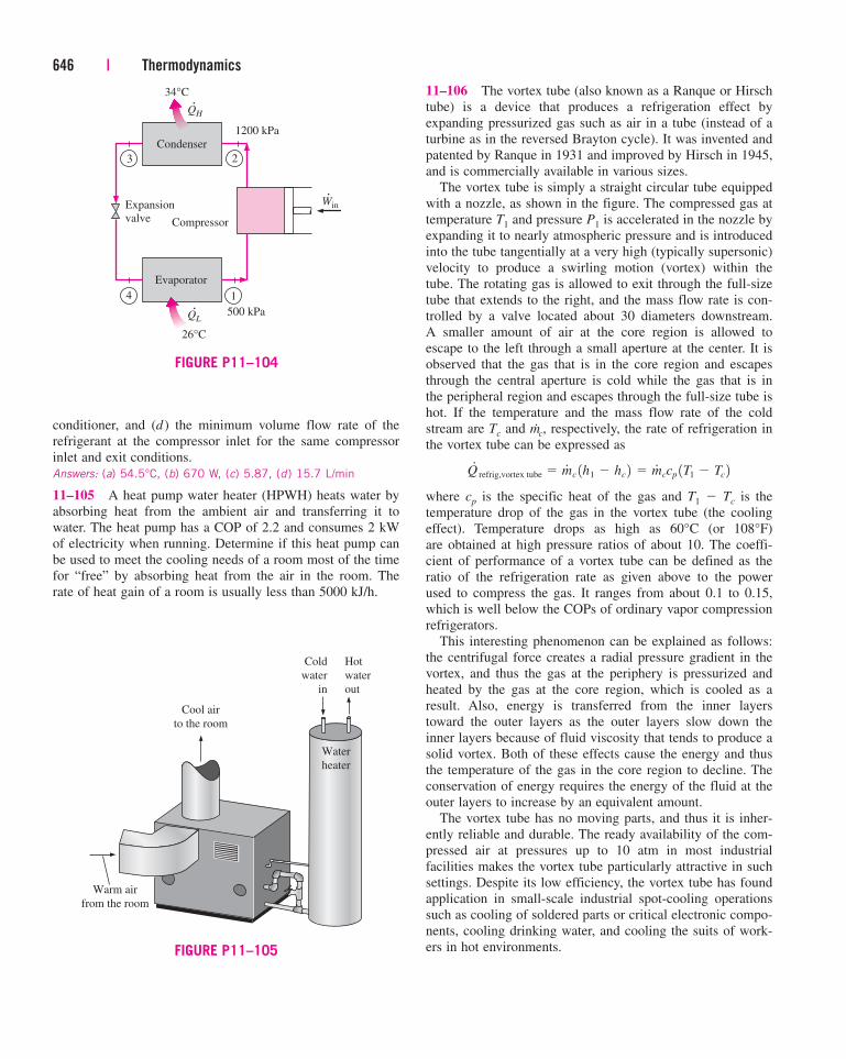
conditioner, and (d ) the minimum volume flow rate of the
refrigerant at the compressor inlet for the same compressor
inlet and exit conditions.
Answers: (a) 54.5°C, (b) 670 W, (c) 5.87, (d) 15.7 L/min
11–105 A heat pump water heater (HPWH) heats water by
absorbing heat from the ambient air and transferring it to
water. The heat pump has a COP of 2.2 and consumes 2 kW
of electricity when running. Determine if this heat pump can
be used to meet the cooling needs of a room most of the time
for “free” by absorbing heat from the air in the room. The
rate of heat gain of a room is usually less than 5000 kJ/h.
646 | Thermodynamics
11–106 The vortex tube (also known as a Ranque or Hirsch
tube) is a device that produces a refrigeration effect by
expanding pressurized gas such as air in a tube (instead of a
turbine as in the reversed Brayton cycle). It was invented and
patented by Ranque in 1931 and improved by Hirsch in 1945,
and is commercially available in various sizes.
The vortex tube is simply a straight circular tube equipped
with a nozzle, as shown in the figure. The compressed gas at
temperature T1 and pressure P1 is accelerated in the nozzle by
expanding it to nearly atmospheric pressure and is introduced
into the tube tangentially at a very high (typically supersonic)
velocity to produce a swirling motion (vortex) within the
tube. The rotating gas is allowed to exit through the full-size
tube that extends to the right, and the mass flow rate is con-
trolled by a valve located about 30 diameters downstream.
A smaller amount of air at the core region is allowed to
escape to the left through a small aperture at the center. It is
observed that the gas that is in the core region and escapes
through the central aperture is cold while the gas that is in
the peripheral region and escapes through the full-size tube is
hot. If the temperature and the mass flow rate of the cold
stream are Tc and m.c, respectively, the rate of refrigeration in
the vortex tube can be expressed as
where cp is the specific heat of the gas and T1 � Tc is the
temperature drop of the gas in the vortex tube (the cooling
effect). Temperature drops as high as 60°C (or 108°F)
are obtained at high pressure ratios of about 10. The coeffi-
cient of performance of a vortex tube can be defined as the
ratio of the refrigeration rate as given above to the power
used to compress the gas. It ranges from about 0.1 to 0.15,
which is well below the COPs of ordinary vapor compression
refrigerators.
This interesting phenomenon can be explained as follows:
the centrifugal force creates a radial pressure gradient in the
vortex, and thus the gas at the periphery is pressurized and
heated by the gas at the core region, which is cooled as a
result. Also, energy is transferred from the inner layers
toward the outer layers as the outer layers slow down the
inner layers because of fluid viscosity that tends to produce a
solid vortex. Both of these effects cause the energy and thus
the temperature of the gas in the core region to decline. The
conservation of energy requires the energy of the fluid at the
outer layers to increase by an equivalent amount.
The vortex tube has no moving parts, and thus it is inher-
ently reliable and durable. The ready availability of the com-
pressed air at pressures up to 10 atm in most industrial
facilities makes the vortex tube particularly attractive in such
settings. Despite its low efficiency, the vortex tube has found
application in small-scale industrial spot-cooling operations
such as cooling of soldered parts or critical electronic compo-
nents, cooling drinking water, and cooling the suits of work-
ers in hot environments.
Q#
refrig,vortex tube � m#
c 1h1 � hc 2 � m#
ccp 1T1 � Tc 2
Compressor
QH
Condenser
1200 kPa
500 kPa
26°C
34°C
QL
Evaporator
WinExpansion
valve
3
4 1
2
·
·
·
FIGURE P11–104
Cold
water
in
Water
heater
Cool air
to the room
Warm air
from the room
Hot
water
out
FIGURE P11–105
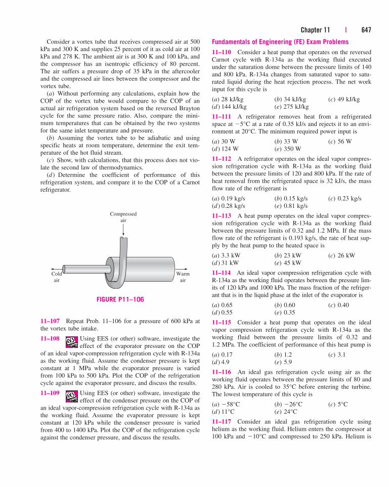
Chapter 11 | 647
Consider a vortex tube that receives compressed air at 500
kPa and 300 K and supplies 25 percent of it as cold air at 100
kPa and 278 K. The ambient air is at 300 K and 100 kPa, and
the compressor has an isentropic efficiency of 80 percent.
The air suffers a pressure drop of 35 kPa in the aftercooler
and the compressed air lines between the compressor and the
vortex tube.
(a) Without performing any calculations, explain how the
COP of the vortex tube would compare to the COP of an
actual air refrigeration system based on the reversed Brayton
cycle for the same pressure ratio. Also, compare the mini-
mum temperatures that can be obtained by the two systems
for the same inlet temperature and pressure.
(b) Assuming the vortex tube to be adiabatic and using
specific heats at room temperature, determine the exit tem-
perature of the hot fluid stream.
(c) Show, with calculations, that this process does not vio-
late the second law of thermodynamics.
(d ) Determine the coefficient of performance of this
refrigeration system, and compare it to the COP of a Carnot
refrigerator.
Fundamentals of Engineering (FE) Exam Problems
11–110 Consider a heat pump that operates on the reversed
Carnot cycle with R-134a as the working fluid executed
under the saturation dome between the pressure limits of 140
and 800 kPa. R-134a changes from saturated vapor to satu-
rated liquid during the heat rejection process. The net work
input for this cycle is
(a) 28 kJ/kg (b) 34 kJ/kg (c) 49 kJ/kg
(d ) 144 kJ/kg (e) 275 kJ/kg
11–111 A refrigerator removes heat from a refrigerated
space at �5°C at a rate of 0.35 kJ/s and rejects it to an envi-
ronment at 20°C. The minimum required power input is
(a) 30 W (b) 33 W (c) 56 W
(d ) 124 W (e) 350 W
11–112 A refrigerator operates on the ideal vapor compres-
sion refrigeration cycle with R-134a as the working fluid
between the pressure limits of 120 and 800 kPa. If the rate of
heat removal from the refrigerated space is 32 kJ/s, the mass
flow rate of the refrigerant is
(a) 0.19 kg/s (b) 0.15 kg/s (c) 0.23 kg/s
(d ) 0.28 kg/s (e) 0.81 kg/s
11–113 A heat pump operates on the ideal vapor compres-
sion refrigeration cycle with R-134a as the working fluid
between the pressure limits of 0.32 and 1.2 MPa. If the mass
flow rate of the refrigerant is 0.193 kg/s, the rate of heat sup-
ply by the heat pump to the heated space is
(a) 3.3 kW (b) 23 kW (c) 26 kW
(d ) 31 kW (e) 45 kW
11–114 An ideal vapor compression refrigeration cycle with
R-134a as the working fluid operates between the pressure lim-
its of 120 kPa and 1000 kPa. The mass fraction of the refriger-
ant that is in the liquid phase at the inlet of the evaporator is
(a) 0.65 (b) 0.60 (c) 0.40
(d ) 0.55 (e) 0.35
11–115 Consider a heat pump that operates on the ideal
vapor compression refrigeration cycle with R-134a as the
working fluid between the pressure limits of 0.32 and
1.2 MPa. The coefficient of performance of this heat pump is
(a) 0.17 (b) 1.2 (c) 3.1
(d ) 4.9 (e) 5.9
11–116 An ideal gas refrigeration cycle using air as the
working fluid operates between the pressure limits of 80 and
280 kPa. Air is cooled to 35°C before entering the turbine.
The lowest temperature of this cycle is
(a) �58°C (b) �26°C (c) 5°C
(d ) 11°C (e) 24°C
11–117 Consider an ideal gas refrigeration cycle using
helium as the working fluid. Helium enters the compressor at
100 kPa and �10°C and compressed to 250 kPa. Helium is
Cold
air
Warm
air
Compressed
air
FIGURE P11–106
11–107 Repeat Prob. 11–106 for a pressure of 600 kPa at
the vortex tube intake.
11–108 Using EES (or other) software, investigate the
effect of the evaporator pressure on the COP
of an ideal vapor-compression refrigeration cycle with R-134a
as the working fluid. Assume the condenser pressure is kept
constant at 1 MPa while the evaporator pressure is varied
from 100 kPa to 500 kPa. Plot the COP of the refrigeration
cycle against the evaporator pressure, and discuss the results.
11–109 Using EES (or other) software, investigate the
effect of the condenser pressure on the COP of
an ideal vapor-compression refrigeration cycle with R-134a as
the working fluid. Assume the evaporator pressure is kept
constant at 120 kPa while the condenser pressure is varied
from 400 to 1400 kPa. Plot the COP of the refrigeration cycle
against the condenser pressure, and discuss the results.
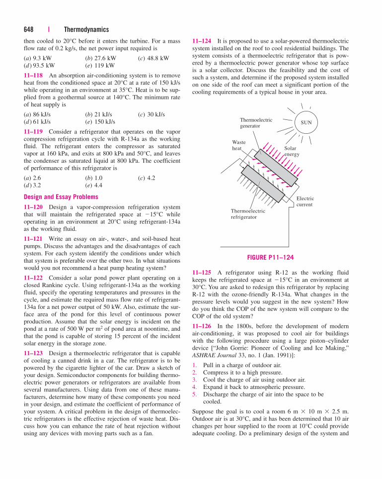
then cooled to 20°C before it enters the turbine. For a mass
flow rate of 0.2 kg/s, the net power input required is
(a) 9.3 kW (b) 27.6 kW (c) 48.8 kW
(d ) 93.5 kW (e) 119 kW
11–118 An absorption air-conditioning system is to remove
heat from the conditioned space at 20°C at a rate of 150 kJ/s
while operating in an environment at 35°C. Heat is to be sup-
plied from a geothermal source at 140°C. The minimum rate
of heat supply is
(a) 86 kJ/s (b) 21 kJ/s (c) 30 kJ/s
(d ) 61 kJ/s (e) 150 kJ/s
11–119 Consider a refrigerator that operates on the vapor
compression refrigeration cycle with R-134a as the working
fluid. The refrigerant enters the compressor as saturated
vapor at 160 kPa, and exits at 800 kPa and 50°C, and leaves
the condenser as saturated liquid at 800 kPa. The coefficient
of performance of this refrigerator is
(a) 2.6 (b) 1.0 (c) 4.2
(d ) 3.2 (e) 4.4
Design and Essay Problems
11–120 Design a vapor-compression refrigeration system
that will maintain the refrigerated space at �15°C while
operating in an environment at 20°C using refrigerant-134a
as the working fluid.
11–121 Write an essay on air-, water-, and soil-based heat
pumps. Discuss the advantages and the disadvantages of each
system. For each system identify the conditions under which
that system is preferable over the other two. In what situations
would you not recommend a heat pump heating system?
11–122 Consider a solar pond power plant operating on a
closed Rankine cycle. Using refrigerant-134a as the working
fluid, specify the operating temperatures and pressures in the
cycle, and estimate the required mass flow rate of refrigerant-
134a for a net power output of 50 kW. Also, estimate the sur-
face area of the pond for this level of continuous power
production. Assume that the solar energy is incident on the
pond at a rate of 500 W per m2 of pond area at noontime, and
that the pond is capable of storing 15 percent of the incident
solar energy in the storage zone.
11–123 Design a thermoelectric refrigerator that is capable
of cooling a canned drink in a car. The refrigerator is to be
powered by the cigarette lighter of the car. Draw a sketch of
your design. Semiconductor components for building thermo-
electric power generators or refrigerators are available from
several manufacturers. Using data from one of these manu-
facturers, determine how many of these components you need
in your design, and estimate the coefficient of performance of
your system. A critical problem in the design of thermoelec-
tric refrigerators is the effective rejection of waste heat. Dis-
cuss how you can enhance the rate of heat rejection without
using any devices with moving parts such as a fan.
648 | Thermodynamics
11–124 It is proposed to use a solar-powered thermoelectric
system installed on the roof to cool residential buildings. The
system consists of a thermoelectric refrigerator that is pow-
ered by a thermoelectric power generator whose top surface
is a solar collector. Discuss the feasibility and the cost of
such a system, and determine if the proposed system installed
on one side of the roof can meet a significant portion of the
cooling requirements of a typical house in your area.
Thermoelectric
refrigerator
Thermoelectricgenerator
Electric
current
Solarenergy
Waste
heat
SUN
FIGURE P11–124
11–125 A refrigerator using R-12 as the working fluid
keeps the refrigerated space at �15°C in an environment at
30°C. You are asked to redesign this refrigerator by replacing
R-12 with the ozone-friendly R-134a. What changes in the
pressure levels would you suggest in the new system? How
do you think the COP of the new system will compare to the
COP of the old system?
11–126 In the 1800s, before the development of modern
air-conditioning, it was proposed to cool air for buildings
with the following procedure using a large piston–cylinder
device [“John Gorrie: Pioneer of Cooling and Ice Making,”
ASHRAE Journal 33, no. 1 (Jan. 1991)]:
1. Pull in a charge of outdoor air.
2. Compress it to a high pressure.
3. Cool the charge of air using outdoor air.
4. Expand it back to atmospheric pressure.
5. Discharge the charge of air into the space to be
cooled.
Suppose the goal is to cool a room 6 m � 10 m � 2.5 m.
Outdoor air is at 30°C, and it has been determined that 10 air
changes per hour supplied to the room at 10°C could provide
adequate cooling. Do a preliminary design of the system and
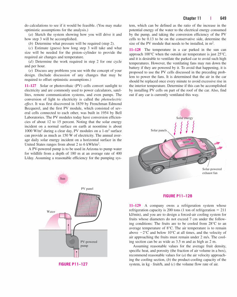
Chapter 11 | 649
do calculations to see if it would be feasible. (You may make
optimistic assumptions for the analysis.)
(a) Sketch the system showing how you will drive it and
how step 3 will be accomplished.
(b) Determine what pressure will be required (step 2).
(c) Estimate (guess) how long step 3 will take and what
size will be needed for the piston–cylinder to provide the
required air changes and temperature.
(d ) Determine the work required in step 2 for one cycle
and per hour.
(e) Discuss any problems you see with the concept of your
design. (Include discussion of any changes that may be
required to offset optimistic assumptions.)
11–127 Solar or photovoltaic (PV) cells convert sunlight to
electricity and are commonly used to power calculators, satel-
lites, remote communication systems, and even pumps. The
conversion of light to electricity is called the photoelectric
effect. It was first discovered in 1839 by Frenchman Edmond
Becquerel, and the first PV module, which consisted of sev-
eral cells connected to each other, was built in 1954 by Bell
Laboratories. The PV modules today have conversion efficien-
cies of about 12 to 15 percent. Noting that the solar energy
incident on a normal surface on earth at noontime is about
1000 W/m2 during a clear day, PV modules on a 1-m2 surface
can provide as much as 150 W of electricity. The annual aver-
age daily solar energy incident on a horizontal surface in the
United States ranges from about 2 to 6 kWh/m2.
A PV-powered pump is to be used in Arizona to pump water
for wildlife from a depth of 180 m at an average rate of 400
L/day. Assuming a reasonable efficiency for the pumping sys-
tem, which can be defined as the ratio of the increase in the
potential energy of the water to the electrical energy consumed
by the pump, and taking the conversion efficiency of the PV
cells to be 0.13 to be on the conservative side, determine the
size of the PV module that needs to be installed, in m2.
11–128 The temperature in a car parked in the sun can
approach 100°C when the outside air temperature is just 25°C,
and it is desirable to ventilate the parked car to avoid such high
temperatures. However, the ventilating fans may run down the
battery if they are powered by it. To avoid that happening, it is
proposed to use the PV cells discussed in the preceding prob-
lem to power the fans. It is determined that the air in the car
should be replaced once every minute to avoid excessive rise in
the interior temperature. Determine if this can be accomplished
by installing PV cells on part of the roof of the car. Also, find
out if any car is currently ventilated this way.
11–129 A company owns a refrigeration system whose
refrigeration capacity is 200 tons (1 ton of refrigeration � 211
kJ/min), and you are to design a forced-air cooling system for
fruits whose diameters do not exceed 7 cm under the follow-
ing conditions: The fruits are to be cooled from 28°C to an
average temperature of 8°C. The air temperature is to remain
above �2°C and below 10°C at all times, and the velocity of
air approaching the fruits must remain under 2 m/s. The cool-
ing section can be as wide as 3.5 m and as high as 2 m.
Assuming reasonable values for the average fruit density,
specific heat, and porosity (the fraction of air volume in a box),
recommend reasonable values for (a) the air velocity approach-
ing the cooling section, (b) the product-cooling capacity of the
system, in kg · fruit/h, and (c) the volume flow rate of air.
Sun
Water
PV-powered
pump
PV panel
FIGURE P11–127
Solar energy
Solar panels
Solar-powered
exhaust fan
FIGURE P11–128