Embed Size (px)
Citation preview
1
©UNENE, all rights reserved. For educational use only, no assumed liability. Electrical Systems – August 2015
CHAPTER 11
Electrical Systems
Prepared byDr. Jin Jiang1
Department of Electrical & Computer EngineeringWestern University
Summary
This chapter covers grid requirements, station power systems, and major electrical componentsin CANDU nuclear power plants (NPP). Grid requirements at an NPP location are discussed interms of reliability and availability of off-site power, the need for a secure electricity supply forthe electrical generation process, and the role of electricity in ensuring the safety of CANDUnuclear power plants. The chapter also describes the operating principles of the major pieces ofelectrical equipment found in a CANDU plant.
The chapter is divided into four parts. In the first part, general and nuclear safety-basedprinciples and practices for the design of electrical systems in CANDU 6 plants are listed.
In the second part, the main electrical connection to the power grid is explained. The conceptsof switchyard, protection schemes, grid connection, and synchronization are also addressedfrom a CANDU NPP point of view. The chapter considers situations involving electric powerproduction during normal operation, as well as power consumption for maintaining plant safetyduring shutdowns. The relationship between internal station power, generated power, and gridpower is clarified in light of reactor safety.
The third part discusses the internal plant electrical system. The section offers a detailedclassification of power sources by their reliability levels and explains the interrelationshipsamong them. The section also provides a justification for the classification of these powersources and introduces the concepts of DC power sources, standby power supplies, andemergency power systems.
The final section briefly introduces the major electrical systems and devices in a CANDU plant,including the generator, transformers, voltage/current transducers, and circuit breakers. Thesection first explains the operating principles of these systems and devices and then providestheir specific ratings and designs in a CANDU plant.
To facilitate learning, a list of exercises has been compiled at the end of the chapter. The reader
1 with contributions of Sections 1.1, 1.2, 3.3, 3.7, 3.8, and 3.9 from Mr. Alek Josefowicz, P.Eng., CANDU Energy(Retired)

2 The Essential CANDU
©UNENE, all rights reserved. For educational use only, no assumed liability. Electrical Systems – August 2015
should attempt to answer these questions to gain further understanding of the materialspresented. Additional information on electrical systems in nuclear power plants can also beobtained through the list of key references provided at the end of the chapter.
It is important to note that electrical systems may vary slightly in different CANDU plants. Forexample, some diagrams may show elements of shared systems, the CANDU 6, as a single unitdesign where the design principles exclude sharing except for the switchyard. The main goal ofthis chapter is to provide a basic knowledge of electrical systems in a CANDU plant, rather thanto examine details of a specific plant.
Learning outcomes
The goal of this chapter is to provide students with a clear understanding of the importance ofthe availability of electrical power for maintaining the safety of a nuclear power plant underconditions different from the normal mode of operation, but which are, however, within theconditions evaluated in the safety analysis report.
Students should be able to explain why grid power is as important to the safety of an NPP asthe power output from the NPP is to the grid.
Students should be able to identify any deficiency in the reliability of the power grid at thepower station location.
Students should be able to read the station power distribution diagram by identifyingdifferent classes of power sources, i.e., Class I through Class IV. They should also be able tomatch the names of the safety-related systems with the corresponding power classes.
Students should be able to describe the relationships among the different classes of powersources.
Students should be able to explain the functionalities of both standby generators and theemergency power system.
Students should be able to list the major systems involved in power generation andtransmission.
Students should be able to explain the principles of energy conversion from mechanicalenergy to electrical energy through synchronous generators.
Students should be able to describe the functionality and working principles of the excitationand cooling systems of the synchronous generators.
Students should be able to describe the working principles of transformers andvoltage/current transducers, as well as to identify where in the plant they are used.

Electrical Systems 3
©UNENE, all rights reserved. For educational use only, no assumed liability. Electrical Systems – August 2015
Students should be able to identify and describe the different types of circuit breakers anddisconnect switches.
Finally, students should be able to explain how the generated electricity is delivered tomillions of customers.
Table of Contents
1 Introduction ............................................................................................................................ 61.1 General............................................................................................................................ 61.2 Nuclear Safety-Based Design Principles and Practices for a CANDU EDS ...................... 6
2 Electrical Power Grids and their Connection with an NPP ..................................................... 72.1 A Holistic View of Electrical Systems between an NPP Station and the Grid................. 72.2 Unique Grid Power Requirements for NPP Safety.......................................................... 82.3 Switchyard between the Grid and a CANDU NPP Station .............................................. 92.4 Summary ......................................................................................................................... 9
3 Electrical Systems Internal to a CANDU Plant....................................................................... 103.1 Sources of Electrical Power for CANDU NPP Station Use............................................. 103.2 Class Definition of Power Sources ................................................................................ 113.3 Channelization .............................................................................................................. 133.4 Electrical Power Sources under Different Classes ........................................................ 14
3.4.1 Class I......................................................................................................................... 143.4.2 Class II........................................................................................................................ 153.4.3 Class III ...................................................................................................................... 163.4.4 Class IV ...................................................................................................................... 16
3.5 Load Transfer among Different Buses .......................................................................... 173.6 Standby Generators (SGs)............................................................................................. 193.7 Emergency Power Systems (EPS).................................................................................. 203.8 Grounding and Lightning Protection ............................................................................ 203.9 Control of Electrical Loads ............................................................................................ 21
3.9.1 Loads powered from switchgear .............................................................................. 213.9.2 Loads powered from the MCC.................................................................................. 213.9.3 Class IV and Class III loads......................................................................................... 223.9.4 Class II and Class I loads ............................................................................................ 223.9.5 EPS loads ................................................................................................................... 22
3.10 Summary ....................................................................................................................... 224 Main Electrical Components in a CANDU Plant.................................................................... 23
4.1 Generators .................................................................................................................... 234.1.1 Basic principle ........................................................................................................... 234.1.2 Generators in a CANDU plant ................................................................................... 264.1.3 Excitation system ...................................................................................................... 274.1.4 Excitation transformer in a CANDU plant ................................................................. 284.1.5 Cooling and protection systems ............................................................................... 29
4.2 Transformers................................................................................................................. 304.2.1 Basic principles.......................................................................................................... 30

4 The Essential CANDU
©UNENE, all rights reserved. For educational use only, no assumed liability. Electrical Systems – August 2015
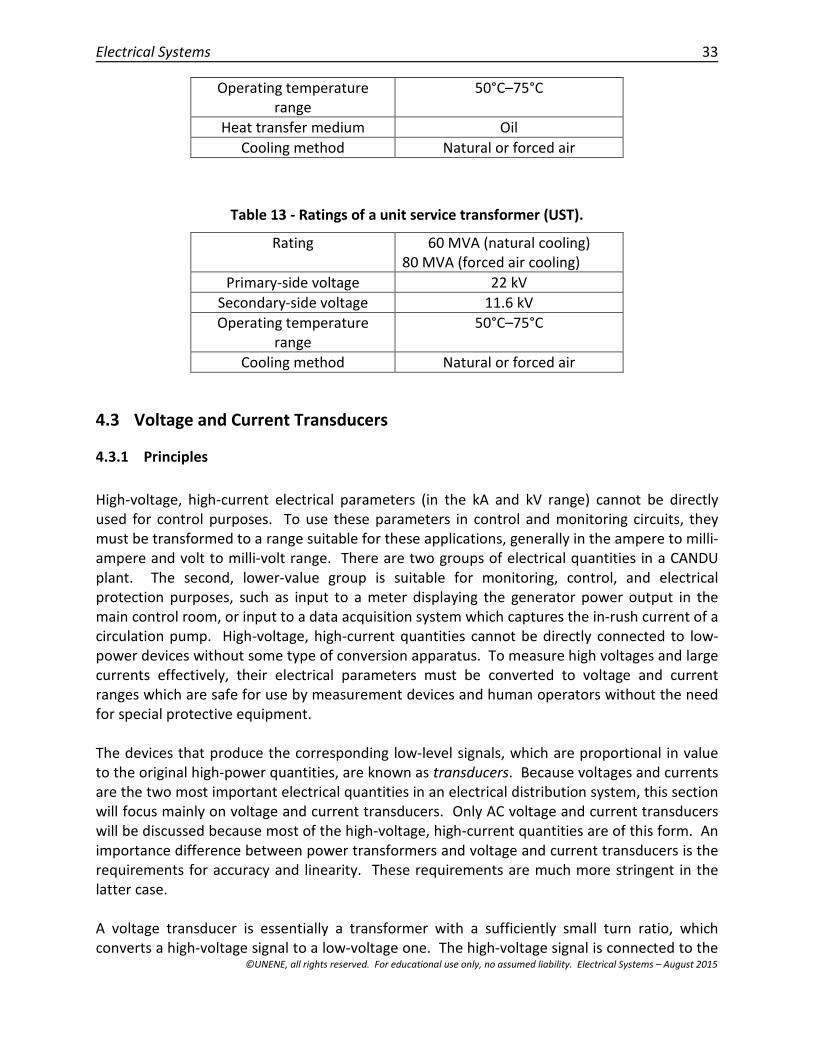
4.2.2 Major transformers in a CANDU plant...................................................................... 324.3 Voltage and Current Transducers ................................................................................. 33
4.3.1 Principles................................................................................................................... 334.3.2 Voltage and current transducers in a CANDU plant ................................................. 35
4.4 Switches, Circuit Breakers, and Disconnect Switches................................................... 354.4.1 Concepts and operating principles ........................................................................... 354.4.2 Switchgear in a CANDU plant.................................................................................... 37
4.5 Summary ....................................................................................................................... 395 Summary and Relationship to other Chapters ..................................................................... 396 Exercise problems................................................................................................................. 407 References ............................................................................................................................ 418 Further Reading .................................................................................................................... 429 Acknowledgements............................................................................................................... 42
List of Figures
Fig. 1 - Relationships between the station power and the power grid [1]..................................... 7Fig. 2 - Voltage levels within a CANDU plant. ............................................................................... 11Fig. 3 - Allowable interruption time vs. capacity of the different power classes. ........................ 11Fig. 4 - Interconnections of different classes of power supplies. ................................................. 12Fig. 5 - Dual-bus configuration for power distribution systems. .................................................. 13Fig. 6 - Load distribution on the Class IV bus in a CANDU plant. .................................................. 18Fig. 7 - Turbine and generator set. ............................................................................................... 24Fig. 8 - Illustrative diagram of a synchronous generator.............................................................. 24Fig. 9 - A two-pole (one pole pair) synchronous generator.......................................................... 24Fig. 10 – Three-phase synchronous generator. ............................................................................ 25Fig. 11 - Conceptual diagram of a static thyristor-based excitation system. ............................... 28Fig. 12 - Basic operating principle of a transformer. .................................................................... 30Fig- 13 - External appearance of a typical power transformer..................................................... 32Fig. 14 - Principles of (a) voltage transducers; and (b) current transducers. ............................... 34Fig. 15 - An over-current protection circuit breaker..................................................................... 36Fig. 16 - An arc-extinguishing circuit breaker. .............................................................................. 39
List of Tables
Table 1 - Classification of power sources...................................................................................... 12Table 2 – Channelization............................................................................................................... 14Table 3 - Equipment supported by Class I power supplies. .......................................................... 15Table 4 - Equipment supported by Class II power supplies. ......................................................... 15Table 5 - Equipment supported by Class III power supplies......................................................... 16Table 6 - Equipment supported by Class IV power supplies......................................................... 17Table 7 - Characteristics of the main generator in a CANDU plant. ............................................. 26Table 8 - Characteristics of the emergency power system generator. ........................................ 27Table 9 - Characteristics of the generator in the Class III power system. .................................... 27
Electrical Systems 5
©UNENE, all rights reserved. For educational use only, no assumed liability. Electrical Systems – August 2015
Table 10 - Characteristics of an excitation transformer. .............................................................. 29Table 11 - Ratings of a main output transformer (MOT).............................................................. 32Table 12 - Ratings of a station service transformer (SST)............................................................. 32Table 13 - Ratings of a unit service transformer (UST). ................................................................ 33Table 14 - Characteristics of SF6 circuit breakers at the generator output. ................................ 37Table 15 - Characteristics of vacuum circuit breakers on an 11.6 kV bus. ................................... 38Table 16 - Characteristics of vacuum circuit breakers on a 6.3 kV bus. ....................................... 38

6 The Essential CANDU
©UNENE, all rights reserved. For educational use only, no assumed liability. Electrical Systems – August 2015
1 Introduction
1.1 General
Even though the sole objective of a nuclear power plant is to generate electricity, it takeselectricity to run the entire plant. The electrical power system in a nuclear power plant is thesubject of this chapter. The electrical systems are designed not only for normal plantoperation, but also for conditions other than normal operation, so that plant safety can bemaintained by ensuring continuity of electrical power supplies regardless of transientdisturbances or faults during operation and post-shutdown. The power for an NPP comes fromdiverse and reliable power sources that are physically and electrically isolated, so that anysingle failure will affect only one source of supply and will not propagate to alternative sources.
Even after the reactor has been shut down, a significant amount of heat is still being producedby the decay of fission products (decay heat). The amount of decay heat is sufficient to causefuel damage if not removed effectively. Therefore, systems must be designed and installed inthe plant to remove decay heat from the core, even in a plant shutdown condition and in theabsence of off-site power sources.
The electrical power distribution system (EDS) is a complete load group distribution systemwith two independent off-site power sources, the main turbine generator, and on-site standbypower sources (standby and EPS diesel generators and, in some cases, a station blackoutgenerator).
1.2 Nuclear Safety-Based Design Principles and Practices for a CANDU EDS
The EDS needs to be designed in accordance with its safety functional requirements asdefined in the safety analysis, including independent and diverse provisions aligned withindependent safety functions and including provision to supply electrical power to secureplant safety during both normal operation and accident conditions without losing all on-site power.
The divisions of the power supply systems should be physically and electrically separatedfrom each other, thus ensuring independence among the divisions as much as possible.
The Group 1 and Group 2 power supply systems should be physically and electricallyseparated from each other as much as practically possible.
The design of the EDS and associated support systems, including I&C, HVAC, andcooling systems, should follow the classification, independence, redundancy, anddiversity requirements placed on Structures, Systems, and Components (SSCs).
The EDS should be designed for a wide range of electrical transients which can beassumed to occur during plant operation and for the assumed environmental conditions.
Electrical Systems 7
©UNENE, all rights reserved. For educational use only, no assumed liability. Electrical Systems – August 2015
The EDS should be designed for or protected from effects of both internal and externalhazards, such as short circuits or loss of the power grid.
The EDS uses commercially available conventional hardware with provisions as dictated by theneed for seismic qualification (SQ), qualification for operation in a harsh environment (EQ), andradiation hardening. Electrical containment penetrations (ECP) form part of containment.
2 Electrical Power Grids and their Connection with an NPP
2.1 A Holistic View of Electrical Systems between an NPP Station and the Grid
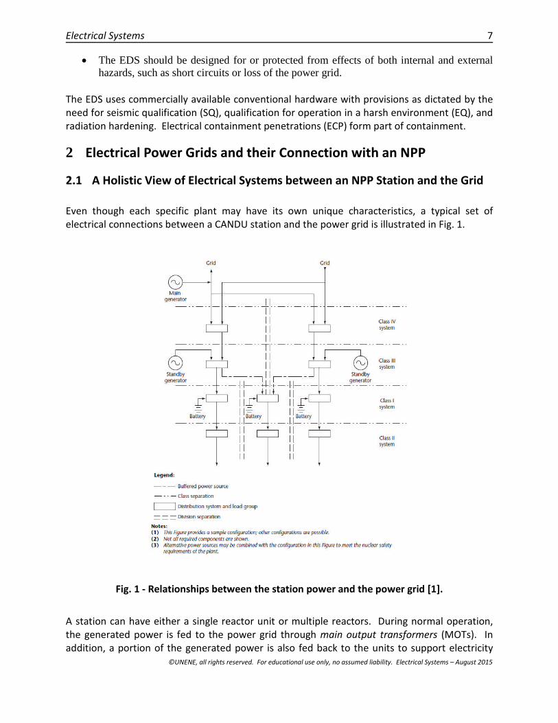
Even though each specific plant may have its own unique characteristics, a typical set ofelectrical connections between a CANDU station and the power grid is illustrated in Fig. 1.
Fig. 1 - Relationships between the station power and the power grid [1].
A station can have either a single reactor unit or multiple reactors. During normal operation,the generated power is fed to the power grid through main output transformers (MOTs). Inaddition, a portion of the generated power is also fed back to the units to support electricity
8 The Essential CANDU
©UNENE, all rights reserved. For educational use only, no assumed liability. Electrical Systems – August 2015
production through unit service transformers (USTs). Furthermore, it is good practice to cross-link multiple units at the switchyard to increase self-reliance within the station, particularly insituations where one shutdown unit may need to draw power from other units within thestation to remove decay heat from the reactor, to maintain essential operating services, or tore-start the reactor as long as it has not been poisoned out by xenon.
When the power from the station units is no longer sufficient or available to meet internaldemand, the station can draw additional power from the grid through station servicetransformers (SSTs). This is also the case during a start-up process.
It is assumed that the power grid is stable and that there are other power sources connected tothe grid, which are available when needed to provide power to the nuclear station site itself.The power flow on the grid can be effectively controlled through grid interconnection andmanagement systems. The NPP may contribute to voltage and power control in the grid.However, most existing CANDU power plants operate in a constant-power output mode tosupport the base load supplied by the grid.
2.2 Unique Grid Power Requirements for NPP Safety
The main objective of a nuclear power plant (NPP) is to produce electricity to support industrial,commercial, and residential loads. Electricity is therefore the final product for most NPPs.However, it is important to realize that about 8% of the electricity produced by the plant isconsumed internally to support power production. This is true for most power plants, such ascoal or gas, although their internal consumption may be significantly lower (<4%). NPPs,however, have unique requirements for electric power availability. It is particularly importantto have a secure electrical supply when an NPP is in a shutdown state and is not producing anyelectricity of its own. Even when the fission process in a nuclear reactor stops, a significantamount of decay heat continues to be generated from the fission products. The amount ofheat is typically so large that continued cooling is absolutely necessary to protect the fuelsheath from melting. Pumping cooling fluid through the core removes this excess heat, butrequires an external electrical power source. Hence, the availability of electrical power (fromother units or from the grid) is crucial for the safety of CANDU and other nuclear power plantsboth under normal operations and in a shutdown state. This includes situations wherethermosiphoning is used. Electrical power is required in this case to maintain water in thesteam generators, although pumping of primary coolant is not needed.
This unique requirement for electricity requires consideration of different scenarios at thedesign stage of NPP electrical systems. In CANDU power plant design, the NPP site must bechosen so that the power grid at the site has multiple feeders from different and independent(often geographically separate) sources, as shown in Fig. 1. This requirement ensures that off-site electrical power sources are available to the station for removing decay heat when thereactor is shut down and is no longer producing electrical power of its own. In addition toCanadian standards [1,2] for a CANDU NPP, the International Atomic Energy Agency has alsoissued guidelines for selecting suitable sites for other types of NPPs based on the reliability and

Electrical Systems 9
©UNENE, all rights reserved. For educational use only, no assumed liability. Electrical Systems – August 2015
availability of off-site power [3,4], as has also The Institute of Electrical and ElectronicsEngineers (IEEE) [5]. As explained in Chapter 13, the availability of off-site electrical power willaffect NPP safety analysis.
As a part of the site selection process, the reliability of the grid must be assessed when some ofits generating capabilities are assumed to be no longer available. This is often referred to as the(N-1) problem [6], where N is the number of available units. A desirable site for an NPP is onewhere power delivery to the NPP site is still guaranteed when only (N-1) or (N-2) suppliers areavailable.
The main cause of the 2011 disaster at Japan’s Fukushima Daiichi nuclear power plant was alack of off-site power due to the earthquake and inadequate protection of on-site standbypower systems against a tsunami. All the plant’s on-site diesel generators operated until theywere damaged by the water brought in by the earthquake-induced tsunami. Hence, the leadingcause of the disaster was the lack of power after the successful shutdown and an initial periodof reactor cooling.
Together with other facilities in a CANDU plant, the electrical systems must also meet theseismic design requirements and qualification processes as outlined in [7] in Canada.
2.3 Switchyard between the Grid and a CANDU NPP Station
Note that even though a single line is used to show the flow of power in Fig. 1, all lines carrythree-phase power (except DC power lines). All transformers, circuit breakers, andtransmission lines in an AC power grid are three-phase devices. When delivering the generatedpower to the grid, the station power must be synchronized with the grid, including the phasesequence, voltage levels, and AC power frequency. Voltage and current transducers are usedfor monitoring and control, and several high-voltage, high-current circuit breakers are placedbetween the MOT and the grid connection points.
The switchyard contains numerous control and protection devices to ensure that any faults onthe grid side will not induce major disturbances to the station, and vice versa. There are alsovarious interlocks to prevent the incorrect operation of power devices, as well as lightningarresters, grounding protection systems, and switchyard control systems.
2.4 Summary
Even though the main function of an NPP is to produce electricity to supply power to the grid,unlike other types of thermal power generation systems, an NPP requires an external powersource with on-site backups to remove decay heat from the reactor when the plant is inshutdown mode and is not producing its own electricity. Therefore, significant designconsiderations have been formulated for the electrical systems within a nuclear power plant.Furthermore, the availability of off-site power also plays a crucial role in nuclear power plant

10 The Essential CANDU
©UNENE, all rights reserved. For educational use only, no assumed liability. Electrical Systems – August 2015
safety and is one of the most important considerations in the site selection process whenconstructing a new NPP.
3 Electrical Systems Internal to a CANDU Plant
3.1 Sources of Electrical Power for CANDU NPP Station Use
Almost all systems within an NPP rely on electrical power to operate. A “defence-in-depth”strategy for electrical power supplies is to rely on diverse, multiple, and independent sources.These sources for a CANDU unit are: (1) power generated from the unit itself; (2) powergenerated from other units within the same station; (3) off-site power obtained from the grid;(4) the emergency power supply; (5) the standby power supply; and (6) batteries. The powersources in a CANDU NPP consist of both AC (alternating current) and DC (direct current) power.“Defence-in-depth” as applicable to the electrical systems can be stated as follows:
1st line – normal operation (grid + main generator) 2nd line – mitigation (standby generators + batteries) 3rd line – station blackout (batteries + designated alternative source(s)) 4th line – severe accident management (additional, diverse, alternative sources).
These sources are arranged in such a way that they supply power to station systems duringnormal operation, as well as during emergency conditions to maintain NPP safety. Theequipment in the station is also graded according to its importance to safety. In an event thatelectrical generation is lost, limited alternative power sources will be used first and foremost tokeep the essential safety-related systems operating.
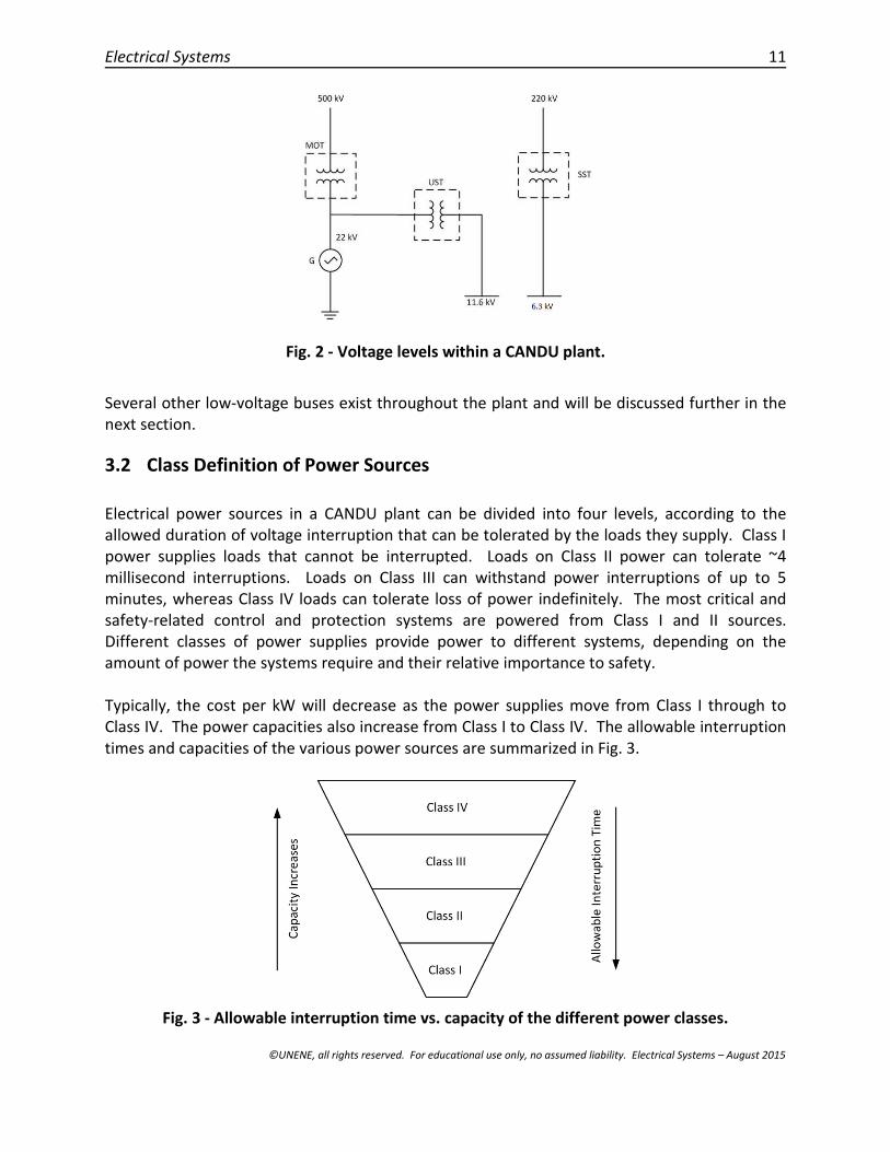
A CANDU plant contains several buses at different voltage levels. The selected voltage levelsmight be different in different plants to meet certain country-specific requirements. Oneexample is shown in Fig. 2, where the output voltage level of the generator is at 22 kV, and thevoltages at the unit service transformer (UST) and the station service transformer (SST) are at11.6 kV and 4.16 kV as secondary voltages. However, in other designs, these voltages could be13.8 kV and 4.16 kV. Also shown in Fig. 2 are two connections to off-site power at the NPP site,one at 500 kV and the other at 220 kV.
Electrical Systems 11
©UNENE, all rights reserved. For educational use only, no assumed liability. Electrical Systems – August 2015
Fig. 2 - Voltage levels within a CANDU plant.
Several other low-voltage buses exist throughout the plant and will be discussed further in thenext section.
3.2 Class Definition of Power Sources
Electrical power sources in a CANDU plant can be divided into four levels, according to theallowed duration of voltage interruption that can be tolerated by the loads they supply. Class Ipower supplies loads that cannot be interrupted. Loads on Class II power can tolerate ~4millisecond interruptions. Loads on Class III can withstand power interruptions of up to 5minutes, whereas Class IV loads can tolerate loss of power indefinitely. The most critical andsafety-related control and protection systems are powered from Class I and II sources.Different classes of power supplies provide power to different systems, depending on theamount of power the systems require and their relative importance to safety.
Typically, the cost per kW will decrease as the power supplies move from Class I through toClass IV. The power capacities also increase from Class I to Class IV. The allowable interruptiontimes and capacities of the various power sources are summarized in Fig. 3.
Fig. 3 - Allowable interruption time vs. capacity of the different power classes.

12 The Essential CANDU
©UNENE, all rights reserved. For educational use only, no assumed liability. Electrical Systems – August 2015
To determine which class of power should be used to supply a specific system, the safetyfunctionalities of the system must be examined, as well as the economic impact if that supplywere unavailable. General criteria for matching the class of power supply to the load that itsupports are summarized in Table 1. They are expressed in terms of the longest powerinterruptions that will not affect the safety of either the NPP or its personnel.
Table 1 - Classification of power sources
Class of power System load characteristics
Class I Power can never be interrupted under postulated conditions
Class II Power can be interrupted up to 4 milliseconds
Class III Power can be interrupted up to 5 minutes
Class IV Power can be interrupted indefinitely
Different stations may have slight variations in electrical power system configurations. Anillustrative diagram showing interconnections in the electrical power system for the differentclasses of power sources in a CANDU station is presented in Fig. 4.
Fig. 4 - Interconnections of different classes of power supplies.
To increase reliability further, Class II, III, and IV power are distributed through two separate

Electrical Systems 13
©UNENE, all rights reserved. For educational use only, no assumed liability. Electrical Systems – August 2015
power divisions. If a failure occurs on one division, the equipment connected to the other buswill still be available. In CANDU plants, these two divisions are typically denoted as “Bus A” and“Bus B” or as “Odd Bus” and “Even Bus”. During design, loads are distributed evenly betweenthese two divisions.
An example of such a split-bus connection is shown in Fig. 5. A symbol with two circles and anarch over them represents a circuit breaker. Circuit breakers are used to connect or disconnectthe systems (denoted as loads) and to protect them whenever a fault occurs. The connectionbetween the Odd and Even buses on the diagram represents two circuit breakers, one on eachbus. To accomplish the connection, both breakers must be manually commanded to close.
Fig. 5 - Dual-bus configuration for power distribution systems.
3.3 Channelization
Important functions use three instrument channels to provide immunity against single instrumentfaults. A control channel consists of interconnected hardware and software components thatprocess one of the duplicated or triplicated signals associated with a single parameter. A controlchannel may include sensors, data acquisition, signal conditioning, data transmission, bypasses,and logic circuits. This defines a subset of instrumentation that can be unambiguously tested oranalyzed from end to end. For safety and high-reliability applications, I&C system design usesthree instrumentation channels with a two-out-of-three voting strategy (i.e., two of the threechannels must be outside the acceptable limits to trip or actuate the system).
To perform on-line tests in such a design, the operator will place the tested channel in a trip state,resulting in the actuation logic performing a one-out-of-two test on the remaining channels.Process and safety systems channels are assigned as shown in Table 2.

14 The Essential CANDU
©UNENE, all rights reserved. For educational use only, no assumed liability. Electrical Systems – August 2015
Table 2 – Channelization.
System(s) SafetyGroup
Odd (A)AssociatedChannels
Third (B)AssociatedChannels
Even (C)AssociatedChannels
RRS and Process 1* A B CSDS1 1 D E FECC (NSQ) 1 K L MSDS2 2 G H JECC (SQ portion) 2 KK LL MMContainment 2 N P Q
The channel association also applies to separation of power supplies and cabling. Duringnormal operation, channels A, B, and C of the UPS supply all their associated channels.
Group 1 is primarily for power production, and Group 2 is only for safety systems.Physical separation is required between the two groups.
Group 2 systems can also be powered from the EPS. Functional and physical separationis maintained even though in this situation, only one EPS generator supplies one bus fromwhich the three channelized power sources are derived.
‘1*’ denotes non-safety, however, it is associated with Group 1, and
NSQ means “not seismically qualified”, and SQ means “seismically qualified”.
3.4 Electrical Power Sources under Different Classes
3.4.1 Class I
Class I power is used to supply loads that cannot be interrupted. It is a DC power source withthree independent distribution channels, each backed with battery banks to provideuninterrupted power to critical loads. To maintain adequate charge on the batteries, each busin Class I is connected to power rectifiers, which convert AC power from Class III power sourcesto DC to charge the batteries, as shown in Fig. 4. During normal operation, power from therectifiers is used to support the load on this bus while charging the batteries at the same time.Hence, the batteries always remain fully charged when power is available. DC/AC inverters arealso used to convert DC power from Class I to Class II. In the event of a loss of Class III power,batteries provide a seamless transfer to support the loads without any interruption. Note thatthe batteries are capable of supplying the load on the DC buses for only about 60 minutes,depending on the particular plant design. This is a very critical time window because all Class Iand II power would be lost if Class III power could not be restored within the interval providedby the batteries.
The loads supported by the Class I power source are very sensitive and are critical to NPP safety

Electrical Systems 15
©UNENE, all rights reserved. For educational use only, no assumed liability. Electrical Systems – August 2015
and operation. A partial list of system equipment powered from Class I is provided in Table 3.
Table 3 - Equipment supported by Class I power supplies.
Class II inverters
DC seal oil pumps for generator
DC lube oil pump for turbine generator bearings
Turbine trip circuits
Turbine turning gear
DC stator cooling pumps
Control and protection systems for station electrical distribution systems
Logic, control, command circuits, and operator interfaces for process andsafety systems (48 VDC)
The capacity of the Class I power source is based on the connected load. CANDU plants useseveral different voltage levels for this DC power supply, including 48V, 220V/250V, and 400V,all to meet the needs of the NPP’s various systems. Note that loss of Class I power is one of theconditions that trigger the shutdown systems.
To prevent service interruption caused by a “single line-to-ground” fault, the 48V DC and 250VDC systems are ungrounded. Ground fault detectors, which produce an alarm whenever aground fault occurs, are provided for each bus.
3.4.2 Class II
Class II power sources are critical to reactor operation. If Class II power is lost, the reactor willbe shut down immediately. Under normal operation, Class II power is obtained from Class Isources through power inverters to convert DC power to AC power, as can be seen in Fig. 4. Iffor any reason the inverters cannot supply a given bus, the Class III power source will be used tosupport Class II power distribution.
The Class II power source supports those devices and systems that can tolerate powerinterruptions on the order of milliseconds. Some typical systems supported by Class II powersource are listed in Table 4.
Table 4 - Equipment supported by Class II power supplies.
Digital control computers
Reactor regulation instrumentation
Electrically operated process valves (600 V power distribution)
Auxiliary oil pumps on the turbine and generator (600 V powerdistribution)
Emergency lighting (600 V power distribution)
Three independent channels of single-phase inverters ensure complete supply independence tothe triplicated instrumentation and I&C. Class II power sources are relatively low-capacity, havetwo voltage levels: 120V and 600V, and are available only in AC form.

16 The Essential CANDU
©UNENE, all rights reserved. For educational use only, no assumed liability. Electrical Systems – August 2015
3.4.3 Class III
Class III power supports large process loads that are unsuitable for Class II power supplies. Theyare used mainly to maintain fuel cooling when the reactor is in a shutdown state and Class IVpower is unavailable. It is important to note that the duration of the loss of Class III powerconsists of only the time required to start up a standby generator and re-load the Class IIIpower system, which is normally about five minutes.
Class III power is taken from Class IV power. In the event of total loss of auxiliary power fromoff-site sources, the auxiliary power required for safe shutdown will be supplied from physicallyand electrically independent diesel generators located on-site. Each power source (the feedsfrom Class IV and the diesel generators) is physically and electrically independent up to thepoint of connection to the Class III buses. This improves the reliability of Class III power, makingit available even in the presence of partial loss of Class IV power sources.
If the Class IV power source for a unit fails completely, it is still possible to obtain Class IV powerfrom other units in a multiple-unit station. Once the standby generators are started, they willprovide power to systems supplied by the Class III power source, ensuring that these criticalsystems remain functional.
Some typical systems supported by Class III power sources are listed in Table 5.
Table 5 - Equipment supported by Class III power supplies.
Auxiliary boiler feed pumps
Auxiliary condensation extraction pumps
Shutdown system cooling pumps
Turbine turning gear
Heat transport feed pumps
Moderator circulating pumps
Class I power rectifiers
Fire water pumps
Emergency core coolant injection pumps
Instrument air compressors
End shield cooling pumps
Service water pumps
The voltage level of Class III power is 4.16 kV, and its capacity can range from 6 to 8 MWe.
3.4.4 Class IV
Of the four classes of power sources in a NPP, Class IV supplies loads that can tolerate infiniteinterruption. This power can come from two sources. During normal operation, Class IV poweris obtained from the main generator through the unit service transformer (UST). Using power

Electrical Systems 17
©UNENE, all rights reserved. For educational use only, no assumed liability. Electrical Systems – August 2015
produced internally by the plant’s own generator minimizes the potential impact ofdisturbances from the grid. Class IV power can also be obtained from the grid through thestation service transformer (SST) when the UST becomes unavailable.
It is important to mention that even though Class IV power supplies the entire station duringoperation, it is not actually required for safe reactor shutdown, although the unit will be shutdown immediately upon experiencing the loss of its Class IV power source.
The loads normally supplied by Class IV power are systems which can tolerate long-term poweroutages without affecting the safety of equipment, personnel, or the public. These loads arenot essential to satisfy fuel cooling requirements following a reactor or turbine trip, but areessential for operation of heat sinks above the shutdown level of reactor power. Some typicalsystems supported by Class IV power sources are listed in Table 6.
Table 6 - Equipment supported by Class IV power supplies.
Main boiler feed pumps
Main heat transport circulating pumps
Condenser cooling water pumps
Generator excitation
Heating and ventilation equipment
Normal lighting systems
As can be seen from Table 6, many important systems in a CANDU plant are supplied by Class IVpower sources, and the loss of Class IV power is considered to be a major incident. Thepreferred voltage levels for Class IV systems are 13.8 kV, 4.16 kV, and 600 V.
3.5 Load Transfer among Different Buses
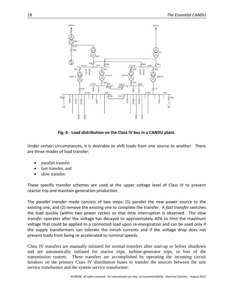
As shown in Tables 3 to 6, NPP system loads are distributed among the various buses based ontheir size and importance to system safety. Although a detailed examination of each load isbeyond the scope of this chapter, Fig. 6 provides an illustrative load diagram for the Class IVand Class III power buses.
18 The Essential CANDU
©UNENE, all rights reserved. For educational use only, no assumed liability. Electrical Systems – August 2015
Fig. 6 - Load distribution on the Class IV bus in a CANDU plant.
Under certain circumstances, it is desirable to shift loads from one source to another. Thereare three modes of load transfer:
parallel transfer fast transfer, and slow transfer.
These specific transfer schemes are used at the upper voltage level of Class IV to preventreactor trip and maintain generation production.
The parallel transfer mode consists of two steps: (1) parallel the new power source to theexisting one, and (2) remove the existing one to complete the transfer. A fast transfer switchesthe load quickly (within two power cycles) so that little interruption is observed. The slowtransfer operates after the voltage has decayed to approximately 40% to limit the maximumvoltage that could be applied to a connected load upon re-energization and can be used only ifthe supply transformers can tolerate the inrush currents and if the voltage drop does notprevent loads from being re-accelerated to nominal speeds.
Class IV transfers are manually initiated for normal transfers after start-up or before shutdownand are automatically initiated for reactor trips, turbine-generator trips, or loss of thetransmission system. These transfers are accomplished by operating the incoming circuitbreakers on the primary Class IV distribution buses to transfer the sources between the unitservice transformer and the system service transformer.

Electrical Systems 19
©UNENE, all rights reserved. For educational use only, no assumed liability. Electrical Systems – August 2015
Automatic transfer systems are also incorporated into Class II. They monitor the operation of thepower inverters and under certain conditions, transfer Class II distribution buses to alternativesupplies directly from Class III. These transfers operate within each channel or division of ClassII.
There are no transfers in the Class I system because each channel’s batteries are charged throughtwo 100%-capacity rectifier-chargers which share the load.
There are no transfers in Class III or in the EPS systems, although it is possible to connect theOdd and Even main distribution buses manually when, following a loss of Class IV power, onlyone standby generator in the system is operating.
Manual source selection is provided for Class I and II power conversion and distribution toaddress the condition when, after a loss of Class IV power, only one standby generator isavailable to power one Class III division.
3.6 Standby Generators (SGs)
To maintain power to safety, safety support, and heat-sink systems following loss of Class IVpower sources, CANDU stations contain additional on-site power sources. One type is knownas standby generators. These generators are not required to be seismically qualified.
This power source is based on two or more generators driven by diesel engines or combustionturbines (in the case of Ontario Power Generation). As shown in Figs. 4 and 6, a generatorsupplies Class III AC power to each Odd and Even bus at a 6.3 kV level. These generators aresupplied with enough fuel to keep the diesel engines running continuously for an extendedperiod of time (up to one week depending on a continued supply of fuel). Standby generatorsystems have their own compressed air and DC power sources for start-up and will startautomatically upon loss of Class IV sources to maintain power to safety and safety supportsystems. The SGs could form a seismically qualified distribution system, but the design hasevolved to create a separate seismically qualified distribution system. The seismically qualifiedsystems are connected to Class III because that is their preferred source of power and areisolated from Class III only when the seismically qualified power sources can provide therequired power. The standby generators will also start whenever a loss-of-coolant accident(LOCA) signal is issued, but will not connect to the buses until a loss of Class IV power occurs.Standby generators should be up and running within 30 seconds after receiving a LOCA signal,picking up all designated loads within a further three minutes. One standby generator hassufficient capacity to supply the required loads.
Because of the critical roles played by standby generators, regular maintenance is criticallyimportant. This typically consists of starting each diesel generator periodically from the localcontrol panel, paralleling it with the respective division of the Class IV supply, and letting thegenerators run for a specified minimum period of time.

20 The Essential CANDU
©UNENE, all rights reserved. For educational use only, no assumed liability. Electrical Systems – August 2015
3.7 Emergency Power Systems (EPS)
The second set of alternative power sources in CANDU plants is known as emergency powersystems. Unlike standby generator systems, these power sources must be seismically qualified[7], and they function completely independently of other power sources. Similarly to standbygenerators, the emergency power systems start automatically upon the loss of Class IV powerand will also start on a LOCA signal. Under such circumstances, back-up generators providepower to the NPP’s critical systems to enable reactor shutdown, monitoring, and decay heatremoval. It is expected that the system should be up and running with its intended loads withinthree minutes.
The following background is relevant to design decisions affecting the EPS:
Based on plant licensing conditions, a loss-of-coolant accident (LOCA) is a random eventbecause the heat transport system is fully seismically qualified and a seismic event,another random event, is not postulated to occur in the first 24 hours after a LOCA. With24 hours of operation of emergency core cooling (ECC) and other required safety supportsystems, a 20–30 minute break can be tolerated in ECC operation. This time is sufficientfor the operators to transition from the main control room (MCR) to the SCA and torestart the ECC and the associated systems.
A total loss of Class IV power coincidental with a subsequent loss of Class III power,both random events (except at Fukushima where Class III was incapacitated by thetsunami, which was induced by the earthquake, but this is a different set of designconditions), but without a LOCA, is a condition in which residual heat is removed fromthe reactor by means of steam generators and water from the dousing tank.Depressurization of the heat transport system is a precondition for this mode of heatremoval. Valves for implementing depressurization and maintaining the requiredmonitoring are powered from a UPS or by compressed air for some valves. There issufficient time for the operators to initiate the EPS to supplement the dousing tankreserve with an emergency water supply (EWS).
3.8 Grounding and Lightning Protection
The grounding system is required to prevent physical injuries and equipment damage in case ofa fault and to minimize electromagnetic effects from ground fault currents as well as to preventinterference and to protect equipment from lightning strikes.
Lightning protection is required so that equipment related to the safety of the nuclear powerplant continues to operate and important monitoring devices continue to function whenlightning hits facilities or power lines.

Electrical Systems 21
©UNENE, all rights reserved. For educational use only, no assumed liability. Electrical Systems – August 2015
3.9 Control of Electrical Loads
Generally, in a typical CANDU power generating station, the electrical loads are remotelycontrolled using the control logic (relay logic) and interposing circuits, both powered from 48 VDC Class I. The output from the control logic is hard-wired to the switchgear and motor controlcentre (MCC) control circuits or to the terminals of a solenoid valve when the valve is controlleddirectly.
Major loads have their mode of operation (ON, AUTO, or STANDBY) selected by the operatorfrom the main control room (MCR) or the secondary control room (SCA). In the AUTO mode,the load will augment the already running load(s) when the process demand exceeds thecapacity of the running load(s). In the STANDBY mode, the load will replace the normallyrunning load when the latter fails to operate.
3.9.1 Loads powered from switchgear
Power to the various loads is switched ON and OFF by an individual circuit breaker at theselected voltage level. The circuit breaker protective relays may be mounted within thebreaker cell, and the relays interposing between the breaker control circuit and the load’scontrol logic are located in separate cubicles or cells, called the relay and terminal (R&T)section, adjacent to each group of circuit breakers.
A typical switchgear control circuit operates from the 250 V DC power source provided by theClass I batteries. The circuit is used to:
Provide power to the operation of stored-energy devices which operate on the close andtrip mechanisms of the circuit breaker.
Close and trip the circuit breaker in response to commands from the:o Unit operator;o Process control system;o Power circuit protective relays.
Operation of the close and trip circuits requires momentary signals. The circuit breakercontrols require manual local reset following a trip due to the operation of power circuitprotective relays.
3.9.2 Loads powered from the MCC
Power to these loads will be switched ON and OFF by contactors in individual combinationstarters. The relays interposing between the contactor control circuit and the load’s controllogic are located in the relay and terminal (R&T) section adjacent to each group of combinationstarters.
The circuit breaker in the combination starter is manually operated and, except for

22 The Essential CANDU
©UNENE, all rights reserved. For educational use only, no assumed liability. Electrical Systems – August 2015
maintenance, remains in the closed position. A typical MCC control circuit operates from the120 V AC power source provided by the starter’s step-down transformer. The circuit is used toenergize and de-energize the contactor in response to commands from the:
Unit operator; Process control system; Circuit breaker protection and overload relays.
To remain energized, the contactor requires a signal to be maintained. The circuit breakerrequires a manual local reset following a trip due to the operation of power circuit protectivefunctions built into the breaker.
3.9.3 Class IV and Class III loads
Typical types of interfacing circuits are:
MCC and switchgear:o Off/On;o Off/Auto/On;o Off/Standby/On;o Off/Standby/Auto/On.
MCC only:o Motorized valve with non-auto control;o Motorized valve with auto control.
Other:o Solenoid valve with non-auto control;o Solenoid valve with auto control.
3.9.4 Class II and Class I loads
Loads energized from the Class II and Class I (UPS) MCCs or panels perform either specialsafety-related or personnel/equipment protection-related functions. The control modes aretherefore limited to OFF/ON or OFF/AUTO/ON and, in the case of motorized valves, toOPEN/CLOSE or OPEN/AUTO/CLOSE and operate in the same way as the Class III and Class IVloads with the same type of controls.
3.9.5 EPS loads
Loads energized from the EPS are controlled in the same way as when they were energizedfrom Class III, II, and I or will be limited to manual OFF/ON controls.
3.10 Summary
The safety and operating reliability of a CANDU NPP depend heavily on availability of electrical

Electrical Systems 23
©UNENE, all rights reserved. For educational use only, no assumed liability. Electrical Systems – August 2015
power to ensure proper operation of its various systems. The electrical power system insidethe plant is divided into four classes: Class I, II, III, and IV. Energy for Class I is stored in batteriesand can be obtained from the rectified power of Class III sources. Class II power is obtainedfrom Class I through DC/AC inverters or directly from Class III. Standby generators providealternative power to Class III and EPS systems. Normally, the plant obtains power from its ownunit through a UST. It is also possible and permitted to operate the plant with Class IV powersupplied through an SST. When a unit stops producing electrical power, power is drawn fromneighbouring units through switchyard connections. This may require manual re-configuration(depending on the event) to supply the shutdown unit(s) from the running unit(s) to removedecay heat. When these power sources are not available, grid power can be used to powerClass IV through the SST. Once Class IV power is lost, the reactor must be shut downimmediately, and heat sink systems are powered from Class III standby generators or the EPS.
In addition, CANDU stations are also equipped with two sets of long-term on-site powersupplies, at least one of which is seismically qualified, which are driven by diesel engines.Within the same class, the Class IV, Class III, and some Class II loads in the plant are distributedon multiple and separate buses depending on the number of loads, their power requirements,and the plant’s Odd/Even bus philosophy. Class I and Class II power to I&C circuits is suppliedthrough three channelized distribution systems from channelized and independent energystorage and conversion systems. Because Class IV buses are capable of receiving power fromeither of two supplies and because automatic transfer of supplies is provided on sensing loss ofpower, reliability of power is ensured, and plant operating safety is increased.
4 Main Electrical Components in a CANDU Plant
4.1 Generators
4.1.1 Basic principle
Electricity output from a CANDU nuclear power plant is generated by a synchronous generator.The generator shaft is directly coupled to that of the steam turbine. The function of thegenerator is to convert mechanical energy from the turbine to electrical energy to supplyelectrical loads. A simple illustrative diagram is shown in Fig. 7.

24 The Essential CANDU
©UNENE, all rights reserved. For educational use only, no assumed liability. Electrical Systems – August 2015
Fig. 7 - Turbine and generator set.
The principle of a generator is based on Faraday’s law of electromagnetic induction. The mainparts of a generator are a stationary iron core and winding, known as the stator, and a rotatingiron core and winding, known as the rotor. When the rotor winding is energized through thefield excitation circuit, as the turbine rotates the rotor, a rotating magnetic field is created. Theexcitation current is supplied to the rotor winding through slip rings. The rotating magnetic fluxinduces a potential in the stator winding. An illustrative diagram is shown in Fig. 8.
Fig. 8 - Illustrative diagram of a synchronous generator.
Due to the relative positions of the magnetic flux and the stator winding, as the rotor turns, theinduced voltage will take on a sinusoidal form. The frequency of the generated voltage will bedirectly related to the rotational speed. For the two-pole (N-S) machine shown in Fig. 9, onefull revolution will produce one full cycle of a sinusoidal wave. If the number of pole pairs onthe rotor is increased, a full revolution of the shaft will produce multiple cycles at the electricaloutput. In other words, it is possible to reduce the rotational speed of the turbine, but still togenerate the desired frequency in the electrical output, by increasing the number of pole pairs.
Fig. 9 - A two-pole (one pole pair) synchronous generator.
The relationship among the speed of rotation ( rpm), the output frequency (Hz), and thenumber of pole pairs () can be stated as follows:

Electrical Systems 25
©U
=60
.
The word synchronous means that the magnetic field rotates in synchronism with the rotor.When the stator windings are placed 120° apart as shown in Fig. 10, a three-phase voltage canbe generated.
When a load is connectepower to the load.
Assume that the currents
The active power output d
The reactive power is
where iM and vM are the p
The angle ߠ is the phasoutput. Hence, the totalas:
NENE, all rights reserved. For educational use only, no assumed liability. Electrical Systems – August 2015
d to the output of the stator winding, the generator will transfer the
from each phase can be represented as:
= ெܫ sinݐ
= ெܫ sin(ݐ− 120°)
= ெܫ sin(ݐ− 240°).
elivered to the load at each phase can be calculated as:
= ெ ெݒ cosߠ MW
= ெ ெݒ sinߠ MVar
hase current and phase voltage.
e difference between the voltage and the current at the generatorreal and reactive power output from all three phases can be expressed
௧௧= 3 = 3 ெ ெݒ cosߠ MW
Fig. 10 – Three-phase synchronous generator.
26 The Essential CANDU
©UNENE, all rights reserved. For educational use only, no assumed liability. Electrical Systems – August 2015
௧௧= 3 = 3 ெ ெݒ ߠݏ MVar
The rated power is
௧ௗ = 3 ெ ெݒ MW
The power factor (pf) is= ߠݏ
Typically, the power factor is maintained between 0.8 and 0.9. The frequency of the generatedpower is controlled by a governor on the turbine, and the generator output voltage iscontrolled by the field excitation through an automatic voltage regulator.
4.1.2 Generators in a CANDU plant
There are several generators in a CANDU plant: (1) the main generator; (2) the standbygenerators; and (3) the generators in the emergency power system.
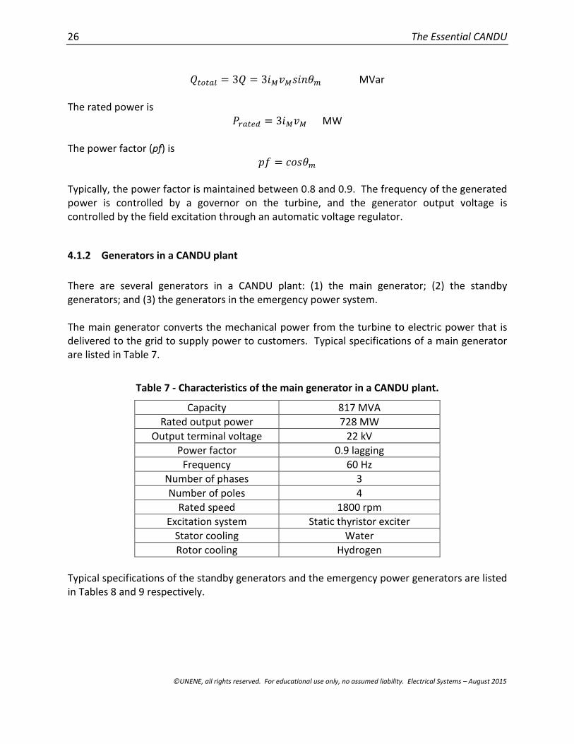
The main generator converts the mechanical power from the turbine to electric power that isdelivered to the grid to supply power to customers. Typical specifications of a main generatorare listed in Table 7.
Table 7 - Characteristics of the main generator in a CANDU plant.
Capacity 817 MVA
Rated output power 728 MW
Output terminal voltage 22 kV
Power factor 0.9 lagging
Frequency 60 Hz
Number of phases 3
Number of poles 4
Rated speed 1800 rpm
Excitation system Static thyristor exciter
Stator cooling Water
Rotor cooling Hydrogen
Typical specifications of the standby generators and the emergency power generators are listedin Tables 8 and 9 respectively.

Electrical Systems 27
©UNENE, all rights reserved. For educational use only, no assumed liability. Electrical Systems – August 2015
Table 8 - Characteristics of the emergency power system generator.
Rated output power 1.6 MW
Rated current 183 A
Output terminal voltage 4.16 kV
Power factor 0.8 lagging
Frequency 60 Hz
Number of phases 3
Number of poles 6
Rated speed 1200 rpm
Table 9 - Characteristics of the generator in the Class III power system.
Rated output power 8.2 MW
Output terminal voltage 4.16 kV
Power factor 0.8 lagging
Frequency 60 Hz
Number of phases 3
Number of poles 12
Rated speed 600 rpm
4.1.3 Excitation system
To create a magnetic field inside a synchronous generator, separate windings and an electricalpower source must be used. This part of the generation system is known as the excitationsystem and is shown in Fig. 12. The excitation system is essentially a controllable DC source. Byadjusting the excitation system output voltage, the output voltage level of the generator can becontrolled, and hence the reactive power output. Because the excitation current must bedelivered to the windings on the rotor, slip rings are used.
Once the generator is running, power for the excitation system can be obtained from theexcitation transformer, which is energized from the Class IV distribution system. The powersource can be either the SST or the UST. However, AC power from the generator must beconverted to DC before it can be delivered to the rotor windings. In the past, a DC generatorcoupled to the synchronous generator shaft was used to produce DC power for the excitationsystem. Nowadays, this conversion is accomplished by a thyristor-based rectifier. Unlike a DCgenerator, this conversion process has no moving parts; hence, it is often referred to as a staticthyristor-based excitation system.
During normal operation, the excitation system is often used to (1) control the output voltagelevel of the generator, and (2) adjust the reactive power output of the generator. A feedbackcontrol system, known as an excitation control system, is also used to ensure that adequateexcitation voltage is applied to maintain the desired generator output voltage level and thereactive power output. These functionalities are essential to improve the reliability of thegenerator system.

28 The Essential CANDU
©UNENE, all rights reserved. For educational use only, no assumed liability. Electrical Systems – August 2015
In the event of an emergency, the excitation system can also be used to provide additionalmeans to improve system stability. For example, when a fault has occurred on the transmissionsystem, the output voltage of the generator can decrease unexpectedly. The excitation systemcan be used to slow down this voltage collapse, thus improving system stability. If a shortcircuit in the generator or at the generator output terminal is detected, the excitation systemcan cut its power immediately to drive the generator output voltage to zero, preventing furtherdamage to the generator.
In a CANDU plant, an excitation transformer is used to step down the generator output voltagefrom 22 kV to 850 V before sending it to the thyristor-based rectifier. However, different plantsmay have different output voltage levels. An illustrative diagram of an excitation system isshown in Fig. 11.
Fig. 11 - Conceptual diagram of a static thyristor-based excitation system.
To start the generator, a separate excitation system must be used. The details will be omittedhere. Once the generator starts to operate, a portion of the generated power is used toprovide the excitation for its magnetic field. The excitation power is obtained by converting aportion of the 22 kV generator output to 850V AC voltage. This voltage is further regulatedthrough an automatic voltage regulator (AVR) and subsequently sent to a thyristor-based staticrectifier to convert the AC voltage to DC voltage before sending it to the rotor through the slipring. The excitation system for the SGs and EPGs is different in that they must start when noadditional sources of AC power are present.
4.1.4 Excitation transformer in a CANDU plant
The excitation transformer is a three-phase transformer. Delta (Δ) connections are used on both primary and secondary sides. Specifications of one such transformer are listed in Table 10.
Electrical Systems 29
©UNENE, all rights reserved. For educational use only, no assumed liability. Electrical Systems – August 2015
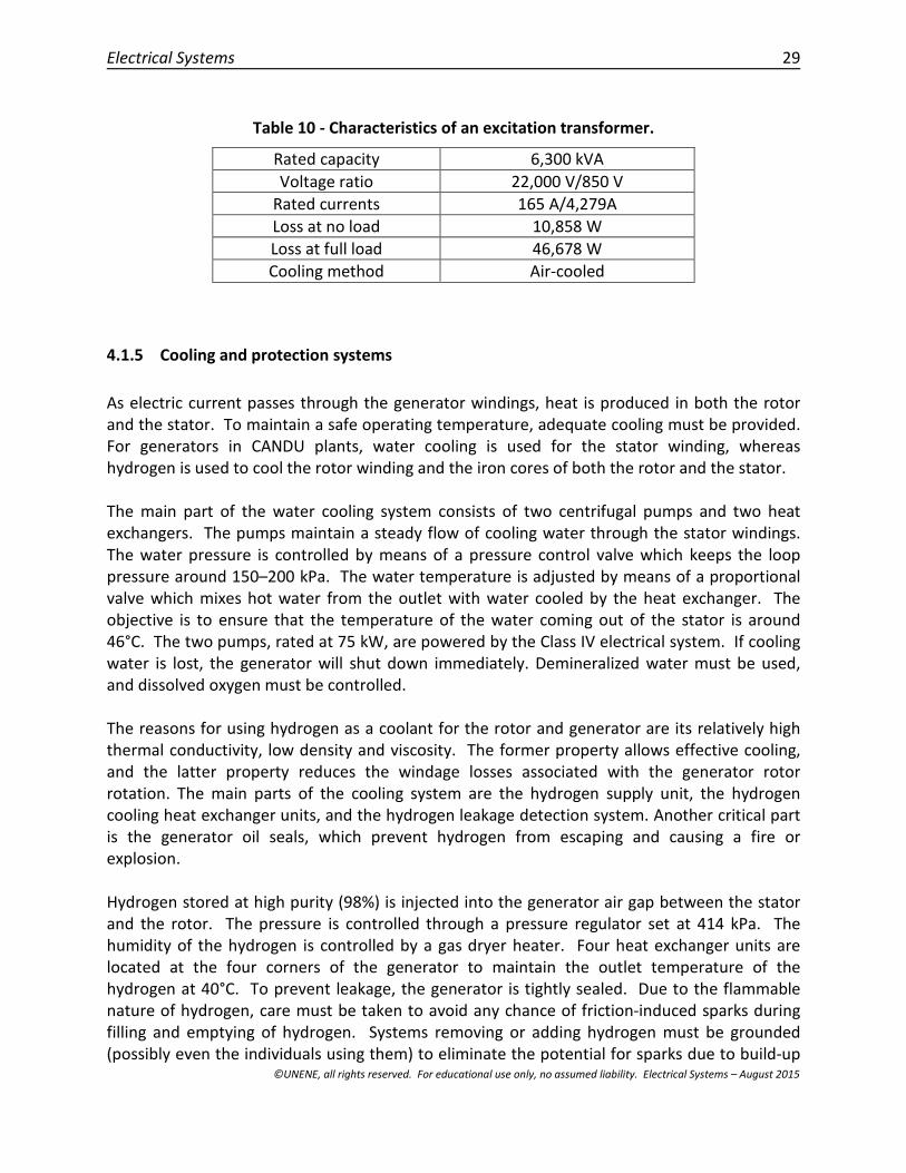
Table 10 - Characteristics of an excitation transformer.
Rated capacity 6,300 kVA
Voltage ratio 22,000 V/850 V
Rated currents 165 A/4,279A
Loss at no load 10,858 W
Loss at full load 46,678 W
Cooling method Air-cooled
4.1.5 Cooling and protection systems
As electric current passes through the generator windings, heat is produced in both the rotorand the stator. To maintain a safe operating temperature, adequate cooling must be provided.For generators in CANDU plants, water cooling is used for the stator winding, whereashydrogen is used to cool the rotor winding and the iron cores of both the rotor and the stator.
The main part of the water cooling system consists of two centrifugal pumps and two heatexchangers. The pumps maintain a steady flow of cooling water through the stator windings.The water pressure is controlled by means of a pressure control valve which keeps the looppressure around 150–200 kPa. The water temperature is adjusted by means of a proportionalvalve which mixes hot water from the outlet with water cooled by the heat exchanger. Theobjective is to ensure that the temperature of the water coming out of the stator is around46°C. The two pumps, rated at 75 kW, are powered by the Class IV electrical system. If coolingwater is lost, the generator will shut down immediately. Demineralized water must be used,and dissolved oxygen must be controlled.
The reasons for using hydrogen as a coolant for the rotor and generator are its relatively highthermal conductivity, low density and viscosity. The former property allows effective cooling,and the latter property reduces the windage losses associated with the generator rotorrotation. The main parts of the cooling system are the hydrogen supply unit, the hydrogencooling heat exchanger units, and the hydrogen leakage detection system. Another critical partis the generator oil seals, which prevent hydrogen from escaping and causing a fire orexplosion.
Hydrogen stored at high purity (98%) is injected into the generator air gap between the statorand the rotor. The pressure is controlled through a pressure regulator set at 414 kPa. Thehumidity of the hydrogen is controlled by a gas dryer heater. Four heat exchanger units arelocated at the four corners of the generator to maintain the outlet temperature of thehydrogen at 40°C. To prevent leakage, the generator is tightly sealed. Due to the flammablenature of hydrogen, care must be taken to avoid any chance of friction-induced sparks duringfilling and emptying of hydrogen. Systems removing or adding hydrogen must be grounded(possibly even the individuals using them) to eliminate the potential for sparks due to build-up

30 The Essential CANDU
©UNENE, all rights reserved. For educational use only, no assumed liability. Electrical Systems – August 2015
of static electricity or from energized equipment. Several hydrogen leakage detectors areinstalled in the vicinity of the generator.
4.2 Transformers
4.2.1 Basic principles
The main function of a transformer is to convert AC electric energy from one voltage level toanother while minimizing the losses in the transformation process. A typical transformer hastwo independent windings. One is referred to as the primary winding, and the other as thesecondary winding. These windings are coupled through a magnetic circuit in the iron core ofthe transformer. Ferromagnetic materials are used to construct the core to confine themagnetic flux inside. An illustrative diagram of a transformer is shown in Fig. 12. It isinteresting to point out that, between the primary and the secondary, there is no directelectrical connection.
Fig. 12 - Basic operating principle of a transformer.
The operating principle of a transformer can be described as follows: the current in the primarywinding creates an alternating magnetic flux, ϕ, inside the core. The strength of this flux isproportional to the current, Ip, as well as to the number of turns in the primary winding, Np. Onthe secondary side, based on Faraday’s law of induction, a potential, Vs, will be induced in thesecondary winding. The level of this induced potential is proportional to the strength of themagnetic flux, ϕ, which is a function of the current, Ip, as well as of the number of turns in thesecondary side, Ns. Therefore, if Ns is larger than Np, the voltage at the secondary will be higherthan that at the primary; such a transformer is often referred to as a step-up transformer. Atransformer with the winding turned the other way around is known as a step-downtransformer.
Most electrical power systems are three-phase systems. The power generated from a three-phase synchronous generator must be connected to three-phase transmission lines through athree-phase transformer. In fact, a three-phase transformer will have three primary windingsand three secondary windings. A three-phase transformer is formed by proper connection ofthese windings on both the primary and secondary sides. For simplicity, only single-phase
Electrical Systems 31
©UNENE, all rights reserved. For educational use only, no assumed liability. Electrical Systems – August 2015
transformers are described in this chapter.
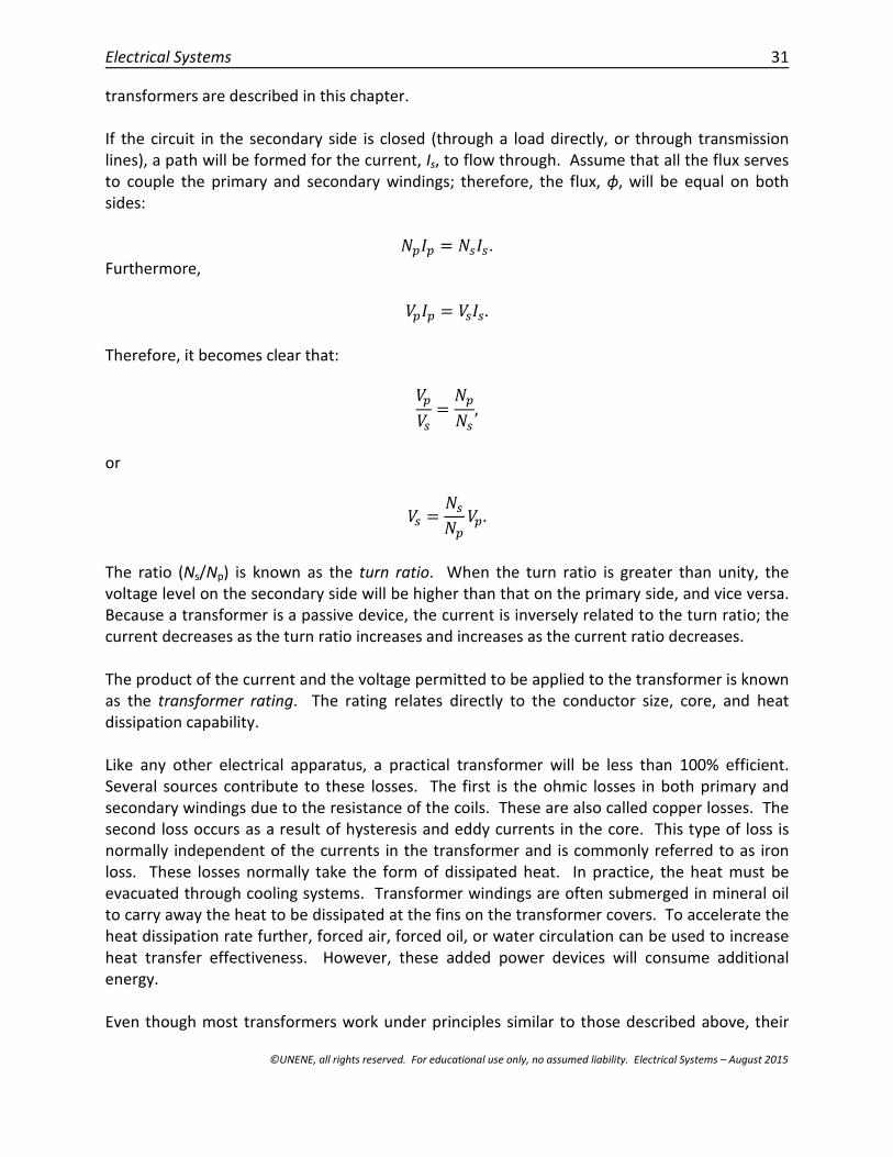
If the circuit in the secondary side is closed (through a load directly, or through transmissionlines), a path will be formed for the current, Is, to flow through. Assume that all the flux servesto couple the primary and secondary windings; therefore, the flux, ϕ, will be equal on bothsides:
ܫ = ௦ܫ௦.
Furthermore,
ܫ = ௦ܫ௦.
Therefore, it becomes clear that:
௦=
௦,
or
௦ =௦
.
The ratio (Ns/Np) is known as the turn ratio. When the turn ratio is greater than unity, thevoltage level on the secondary side will be higher than that on the primary side, and vice versa.Because a transformer is a passive device, the current is inversely related to the turn ratio; thecurrent decreases as the turn ratio increases and increases as the current ratio decreases.
The product of the current and the voltage permitted to be applied to the transformer is knownas the transformer rating. The rating relates directly to the conductor size, core, and heatdissipation capability.
Like any other electrical apparatus, a practical transformer will be less than 100% efficient.Several sources contribute to these losses. The first is the ohmic losses in both primary andsecondary windings due to the resistance of the coils. These are also called copper losses. Thesecond loss occurs as a result of hysteresis and eddy currents in the core. This type of loss isnormally independent of the currents in the transformer and is commonly referred to as ironloss. These losses normally take the form of dissipated heat. In practice, the heat must beevacuated through cooling systems. Transformer windings are often submerged in mineral oilto carry away the heat to be dissipated at the fins on the transformer covers. To accelerate theheat dissipation rate further, forced air, forced oil, or water circulation can be used to increaseheat transfer effectiveness. However, these added power devices will consume additionalenergy.
Even though most transformers work under principles similar to those described above, their

32 The Essential CANDU
©UNENE, all rights reserved. For educational use only, no assumed liability. Electrical Systems – August 2015
appearance can vary greatly. A typical transformer found in a nuclear power plant is illustratedin Fig. 13. The high-power terminals are located at the top of the transformer, where threeisolated connections can be seen. Electric fans are used to create forced air circulation toincrease the heat dissipation rate.
Fig- 13 - External appearance of a typical power transformer.
4.2.2 Major transformers in a CANDU plant
In a CANDU plant, there are many transformers serving different purposes. However, threemain transformers deserve special attention:
Main output transformer (MOT) Station service transformers (SSTs) Unit service transformers (USTs).
Their functionalities have been explained in Section 2, and their specifications are given inTables 11 through 13.
Table 11 - Ratings of a main output transformer (MOT).
Rating 3 × 277 MVA
Primary-side voltage 22 kV
Secondary-side voltage 500 kV
Temperature (oil) 45°C
Temperature (winding) 65°C
Cooling method Forced oil and forced air
Table 12 - Ratings of a station service transformer (SST).
Rating 60 MVA (natural cooling)80 MVA (forced air cooling)
Primary-side voltage 220 kV
Secondary-side voltage 11.6 kV
Electrical Systems 33
©UNENE, all rights reserved. For educational use only, no assumed liability. Electrical Systems – August 2015
Operating temperaturerange
50°C–75°C
Heat transfer medium Oil
Cooling method Natural or forced air
Table 13 - Ratings of a unit service transformer (UST).
Rating 60 MVA (natural cooling)80 MVA (forced air cooling)
Primary-side voltage 22 kV
Secondary-side voltage 11.6 kV
Operating temperaturerange
50°C–75°C
Cooling method Natural or forced air
4.3 Voltage and Current Transducers
4.3.1 Principles
High-voltage, high-current electrical parameters (in the kA and kV range) cannot be directlyused for control purposes. To use these parameters in control and monitoring circuits, theymust be transformed to a range suitable for these applications, generally in the ampere to milli-ampere and volt to milli-volt range. There are two groups of electrical quantities in a CANDUplant. The second, lower-value group is suitable for monitoring, control, and electricalprotection purposes, such as input to a meter displaying the generator power output in themain control room, or input to a data acquisition system which captures the in-rush current of acirculation pump. High-voltage, high-current quantities cannot be directly connected to low-power devices without some type of conversion apparatus. To measure high voltages and largecurrents effectively, their electrical parameters must be converted to voltage and currentranges which are safe for use by measurement devices and human operators without the needfor special protective equipment.
The devices that produce the corresponding low-level signals, which are proportional in valueto the original high-power quantities, are known as transducers. Because voltages and currentsare the two most important electrical quantities in an electrical distribution system, this sectionwill focus mainly on voltage and current transducers. Only AC voltage and current transducerswill be discussed because most of the high-voltage, high-current quantities are of this form. Animportance difference between power transformers and voltage and current transducers is therequirements for accuracy and linearity. These requirements are much more stringent in thelatter case.
A voltage transducer is essentially a transformer with a sufficiently small turn ratio, whichconverts a high-voltage signal to a low-voltage one. The high-voltage signal is connected to the

34 The Essential CANDU
©UNENE, all rights reserved. For educational use only, no assumed liability. Electrical Systems – August 2015
primary side, and the low-voltage signal is generated on the secondary side. As discussed inSection 4.2.1, transformers have the unique ability to isolate the high-voltage primary side fromthe secondary side electrically. The low voltage carries the same amount of information as thehigh voltage, but at a lower electrical potential, making it safer for maintenance personnel andfor equipment designed to operate at lower voltage levels.
An illustrative diagram of a single-phase voltage transducer is shown in Fig. 14(a). When a highvoltage, ଵ, is applied, the transducer will produce a corresponding low voltage, ଶ. The voltageratio is determined by the turn ratio of the primary and secondary windings, i.e.,
ଶ =ேమ
ேభଵ,
where (ேమ
ேభ) is less than unity and represents the voltage reduction factor.
The principle of a single-phase current transducer is shown in Fig. 14(b). The relationshipbetween the current on the primary side and that on the secondary side can be expressed asfollows:
ଶܫ =ଵଶ
,ଵܫ
where (ேభ
ேమ) determines the current reduction factor.
(a)
(b)
Fig. 14 - Principles of (a) voltage transducers; and (b) current transducers.

Electrical Systems 35
©UNENE, all rights reserved. For educational use only, no assumed liability. Electrical Systems – August 2015
4.3.2 Voltage and current transducers in a CANDU plant
There are many voltage and current transducers throughout the plant that provide informationon voltage and current levels in real time for control and monitoring purposes. Four sets ofcurrent transducers are located at the generator output, each with a rating of 1,700A / 5A.There are also two voltage transducers at the generator output, both having a reduction ratioof 22kV/100V. Similar devices are also used for electrical protection of major transformers,such as excitation transformers. A capacitor voltage transformer is used for high-voltagemeasurement at the grid connection point to provide information necessary for plantoperation, as well as for protective relaying.
4.4 Switches, Circuit Breakers, and Disconnect Switches
4.4.1 Concepts and operating principles
There are many electrical switches in a CANDU plant. The most common are those used to turncertain pieces of equipment such as lights, pumps, or instruments on and off. A switch that isturned to the on position (closed) allows electricity to pass through, whereas turning it off(opening it) breaks the electrical circuit and stops the flow of electrons. In a low-powerenvironment, the switches are not much different from those in everyday use.
As voltage and current levels increase, the construction and operation of these switchesbecomes more complex. High-voltage or high-current switches are often known as circuitbreakers, disconnect switches, and contactors. As the names imply, one of the importantfunctions of such devices is to conduct or break the current flow in a circuit. There are twomain scenarios which call for such actions: (1) to execute a control command, such as to start orstop a load, and (2) to cut off the current flow in an abnormal operating condition such as ashort-circuit fault. A circuit breaker must be able to carry and to interrupt current as needed.
An illustrative diagram of an over-current protection circuit breaker is shown in Fig. 15. Thebreaker is connected in series with the circuit. If there is no manual tripping signal, or if thecurrent is within the operating limit, the breaker remains closed. If either a manual trippingsignal is issued (by pushing a button) or if the measured current exceeds the threshold, thetripping coil will generate a trip signal to open the breaker, thereby interrupting the currentflow.

36 The Essential CANDU
©UNENE, all rights reserved. For educational use only, no assumed liability. Electrical Systems – August 2015
Fig. 15 - An over-current protection circuit breaker.
A significantly high voltage can be induced between the two contacts of the circuit breakerwhen it interrupts the current flow. As the contacts separate, the resistance between themincreases rapidly, producing hot spots between the contacts. The high voltage between thecontacts can also form a very strong electrical field. As the particles between the contactsbecome ionized, electric arcing occurs, which will prolong the time taken for the current toreach zero. To minimize the impact of short circuits and reduce wear and tear on the breakercontacts, the arc must be extinguished quickly. The breaker and bus bars must be designed towithstand the mechanical forces resulting from short-circuit currents. Depending on theduration of the short circuits, the amount of mechanical bracing may need to be increased.
Depending on the method of arc extinction, circuit breakers can be classified as:
Air-break circuit breakers Air-blast circuit breakers Vacuum circuit breakers SF6 circuit breakers.
An air-break circuit breaker relies on the high-resistance interruption principle by rapidlylengthening the arc through an arc runner. The arc resistance is increased to such an extentthat the arc can no longer be sustained. Such types of breakers are mainly used in low- andmedium-voltage circuits.
In an air-blast circuit breaker, high-pressure air is blasted into the arc, blowing away the ionizedgas between the contacts to extinguish the arc. The voltage and current that can beinterrupted by an air-blast circuit breaker are normally higher than in an air-break circuitbreaker. As its name implies, the contacts in a vacuum circuit breaker operate in a vacuuminterrupter chamber. The arc is generated by ionization of the contact material, whereas in anair breaker, it is generated by the arc material as well as air ionization. Hence, in a vacuum, thearc is immediately extinguished once the voltage can no longer sustain the plasma created at

Electrical Systems 37
©UNENE, all rights reserved. For educational use only, no assumed liability. Electrical Systems – August 2015
the contact. The cost of the vacuum circuit breaker is relatively high, and they are often used incircuits at less than 38 kV.
SF6 circuit breakers are the most common for high-voltage and high-current circuits. SF6 isshort for sulphur hexafluoride, a gas which satisfies the requirements of an ideal arc-interrupting medium. SF6 gas has high dielectric strength and is colourless, odourless, and non-toxic, with high thermal conductivity. It is also highly stable and non-flammable and does notcause corrosion when in contact with the metallic parts of a circuit breaker. SF6 circuitbreakers can be found in circuits with voltages ranging from 3 kV up to 1000 kV.
Circuit breakers should not be confused with disconnect switches. Disconnect switches do nothave any arc-extinction capability and therefore cannot be used to interrupt a current flow.Such switches are instead used to provide another layer of protection for repair or maintenancecrews, enabling them to isolate the section of a circuit being serviced. Disconnect switches canbe operated either manually or automatically (in the case of motorized switches, such as astarter).
4.4.2 Switchgear in a CANDU plant
There are many types of circuit breakers in a CANDU plant that provide control and electricalprotection functions. Circuit breakers are installed in the plant to facilitate operation andelectrical protection of transformers or electrical distribution bus bars. An illustrative drawingof an arc-extinguishing breaker is shown in Fig. 16. SF6 circuit breakers are used for high-voltage switchyard circuits, whereas vacuum breakers can be used at medium voltage levels(11.6 kV/6.3 kV). These breakers can be operated manually, automatically, or by remotecontrol. The major types of high-voltage circuit breakers in a CANDU plant are described inTables 14 to 16.
Table 14 - Characteristics of SF6 circuit breakers at the generator output.
Voltage level 24 kV
Rated voltage 30 kV
Rated current 24 kA
Rated capacity 1,000 MVA
Breaker closing time Less than 42 ms
Breaker opening time Less than 42 ms
Arc extinction time Less than 60 ms

38 The Essential CANDU
©UNENE, all rights reserved. For educational use only, no assumed liability. Electrical Systems – August 2015
Table 15 - Characteristics of vacuum circuit breakers on an 11.6 kV bus.
Voltage level 11.6 kV
Rated voltage 15 kV
Rated current 2,000–3,000 A
Rated capacity 1,000 MVA
Breaker closing time 45–60 ms
Breaker opening time 30–45 ms
Arc extinction time 5–17 ms
Table 16 - Characteristics of vacuum circuit breakers on a 6.3 kV bus.
Voltage level 6.3 kV
Rated voltage 8.25 kV
Rated current 1,200 A
Rated capacity 500 MVA
Breaker closing time 45–60 ms
Breaker opening time 30–45 ms
Arc extinction time 5–17 ms
Disconnect switches are often found in series with circuit breakers to provide additionalprotection for workers. A disconnect switch is used in series with the circuit breaker at thegenerator output. The rated voltage of this switch is 24 kV, the current is 24 kA, and themaximum short-circuit current is 160 kA. Note that disconnect switches are not used tointerrupt current in circuits. They are used for isolation purposes (worker safety and loadisolation), as well as to reconfigure a network. They are installed to provide additional safetymeasures for maintenance crews working on the power line. There are also fuses installed inmany electric systems throughout the plant to isolate short circuits or unforeseen faults.

Electrical Systems 39
©UNENE, all rights reserved. For educational use only, no assumed liability. Electrical Systems – August 2015
Fig. 16 - An arc-extinguishing circuit breaker.
4.5 Summary
A generator is an energy conversion device that converts mechanical energy from the turbineto electrical energy to supply the load. Together with the generator, there are several otherauxiliary electrical systems in an NPP, such as circuit breakers, transformers, andvoltage/current transducers. In this section, the general principles of these systems have beenfirst explained, followed by information specific to CANDU NPPs. After completing this section,the reader should have a good understanding of how such systems operate, includingknowledge of CANDU-specific applications.
5 Summary and Relationship to other Chapters
Even though the sole objective of a CANDU NPP is to produce electricity, this chapter isrelatively independent of the other chapters in this book. To achieve a better understanding ofthe functionality of the different classes of power sources with respect to safety, the studentshould read Chapter 13 on Reactor Systems first to learn about the different safety systems andsafety functions in a CANDU NPP.

40 The Essential CANDU
©UNENE, all rights reserved. For educational use only, no assumed liability. Electrical Systems – August 2015
6 Exercise problems
1. State the reasons why an NPP is different from a fossil-fuel power plant in terms of itsstation power requirements.
2. From a power grid point of view, what criteria are used to select a suitable site forconstruction of a new NPP?
3. Why is off-site power so important to the safety of an NPP?
4. In your own words, explain the meaning of “odd/even power supplies”.
5. List and define four classes of power used in a CANDU NPP.
6. State the original energy sources of the different classes of power sources.
7. State the sequences under loss of Class III power.
8. State the sequences under loss of Class IV power.
9. Why are batteries used in Class I power supplies?
10. Which class of power is used to charge the batteries in Class I power sources?
11. Explain the sources of power for each power class under both normal and emergencyconditions.
12. Explain the role of grid power during the start-up and shutdown of a CANDU reactor.
13. What role do standby generators play in an NPP, and which class of power supply dothey support?
14. What are the main differences between standby generators and an emergency powersystem?
15. Explain the different power sources that a CANDU plant has and the reasons for this.
16. List the main elements inside a generator.
17. Explain the principle of a synchronous generator used in a CANDU NPP.
18. What is the relationship between the number of generator pole pairs, the rotational speed,and the frequency of the voltage at the generator output?
19. Why is excitation important for synchronous generators?

Electrical Systems 41
©UNENE, all rights reserved. For educational use only, no assumed liability. Electrical Systems – August 2015
20. How is excitation implemented in a CANDU NPP?
21. What is the function of the excitation transformer?
22. How is a generator cooled in a CANDU plant?
23. Under what conditions can the generator be connected to the power grid?
24. How are current and voltage measured in a CANDU plant?
25. What is the main function of a transformer?
26. Identify step-up and step-down transformers used in a CANDU plant.
27. Why are the coils in large-capability transformers often submerged in mineral oil?
28. What is the main function of the station transformer?
29. Why are protection devices important in a switchyard?
30. Explain the working principle of SF6 breakers.
31. What is the difference between a circuit breaker and a disconnect switch?
32. What is the function of a switchyard?
7 References
[1] Canadian Standards Association (CSA), Requirements for Electrical Power and Instrument AirSystems of CANDU Nuclear Power Plants (N290.5-06), 2011.
[2] CNSC Regulatory Document 2.5 Physical Design, Design of Electrical Power Systems forNuclear Power Plants and Small Reactor Facilities (Draft stage).
[3] IAEA, Interaction of Grid Characteristics with Design and Performance of Nuclear PowerPlants - A Guidebook, 1983.
[4] IAEA, Electric Grid Reliability and Interface with Nuclear Power Plants, No. NG-T-3.8, 2012.
[5] IEEE, Standard for Preferred Power Supply (PPS) for Nuclear Power Generating Stations(NPGS) Standard 765-2012, 2013.
[6] H. Ren, I. Dobson, B.A. Carreras, “Long-Term Effect of the n-1 Criterion on Cascading LineOutages in an Evolving Power Transmission Grid”, IEEE Trans. on Power Systems, Vol. 23, pp.1217–1225, 2008.
42 The Essential CANDU
©UNENE, all rights reserved. For educational use only, no assumed liability. Electrical Systems – August 2015
[7] CSA, General Requirements for Seismic Design and Qualification of CANDU Nuclear PowerPlants, N289.1-08, 2008.
8 Further Reading
L.L. Grigsby, Power Engineering Handbook, CRC Press, IEEE Press, 2000 (ISBN-10: 0849385784).
IAEA, Design of Emergency Power Systems for Nuclear Power Plants, NS-G-1.8, 2004 (ISBN 92–0–103504–7).
P. Kiameh, Electrical Equipment Handbook: Troubleshooting and Maintenance, McGraw-Hill,2003 (ISBN-10: 0071396039).
P. Kundur, Power System Stability and Control, McGraw-Hill Professional, 1994 (ISBN 0-07-035958-X).
J.D. McDonald, Electric Power Substation Engineering (2nd ed.), CRC Press, 2007 (ISBN-10:0849373832).
9 AcknowledgementsThe following reviewers are gratefully acknowledged for their hard work and excellentcomments during the development of this Chapter. Their feedback has much improved it. Ofcourse the responsibility for any errors or omissions lies entirely with the author.
Pel CastaldoAlan HepburnAlek Josefowicz
Thanks are also extended to Diana Bouchard for expertly editing and assembling the final copy.


![Wind Farm Electrical Systems.pptx [Read-Only]ewh.ieee.org/r3/atlanta/ias/Wind Farm Electrical Systems.pdf · 2010. 1. 19. · Wind Farm Electrical Systems. ... Maintenance Hoist](https://img.pdfslide.us/doc/110x75/6122e4b36403441c092ee882/wind-farm-electrical-read-onlyewhieeeorgr3atlantaiaswind-farm-electrical.jpg)