Embed Size (px)
Citation preview

1
CHAPTER 1
2
1. INTRODUCTION
Tennis tutor is an automated, smart ball throwing machine which
greatly helps the player to train in a better way. Most of the ball throwing
machines available in India are imported and costly, so there came an idea
to design and build a cost efficient machine with added features. The
general specifications of the tutor machines involve the type of spin
induced on the ball and the portion of the court where the ball is to be
thrown. Apart from this, the tennis tutor brings in the features of remotely
controlling the machine through an app in our mobile phone. The app also
gives us statistical information about the hours of training, level of training,
etc. The smart feature of this product is the use of Myo armband, the
gesture recognition device to easily control various parameters of the
machine. Tennis tutor will be built on the myRIO Platform. The product
involves controlling various DC motors, servo motors and wiper motors. It
also runs algorithms that precisely control various parameters and throw
the ball in the desired direction. It also communicates with our mobile
phone app via Bluetooth and also interfaces with Myo. The various
interfaces are done with the help of the Bluetooth module HC-06.

3
CHAPTER 2
4
2. PROPOSED METHODOLOGY
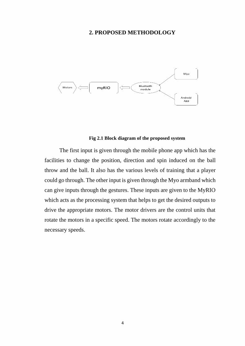
Fig 2.1 Block diagram of the proposed system
The first input is given through the mobile phone app which has the
facilities to change the position, direction and spin induced on the ball
throw and the ball. It also has the various levels of training that a player
could go through. The other input is given through the Myo armband which
can give inputs through the gestures. These inputs are given to the MyRIO
which acts as the processing system that helps to get the desired outputs to
drive the appropriate motors. The motor drivers are the control units that
rotate the motors in a specific speed. The motors rotate accordingly to the
necessary speeds.

5
CHAPTER 3
6
3. HARDWARE DESCRIPTION
The hardware section of the system has two parts.
Electronic Section
o NI myRIO
o Bluetooth module HC-06
o Myo Armband
o DC motor driver – MD30C
Mechanical Section
3.1 ELECTRONIC SECTION
3.1.1 NI myRIO - DEVICE DESCRIPTION
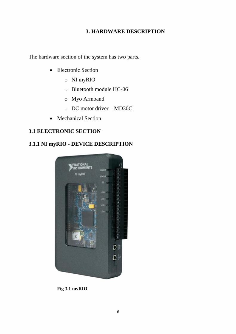
Fig 3.1 myRIO
7
National Instruments has been working on a device called NI
myRIO, an hardware & software platform that aims at giving engineering
students the ability to design real systems quickly for automation, robotics,
data logging or embedded systems. The hardware is based on Xilinx Zynq-
7010 with a dual-core ARM Cortex-A9 processor and an FPGA with
28,000 programmable logic cells, and features 10 analog inputs, 6 analog
outputs, audio I/O channels, and up to 40 lines of digital input/output
(DIO). The National Instruments myRIO-1900 is a portable reconfigurable
I/O (RIO) device that students can use to design control, robotics, and
mechatronics systems. The pinouts, connectivity information, dimensions,
mounting instructions, and specifications for the NI myRIO-1900 are
described in the following sections.
3.1.2 HARDWARE SPECIFICATION
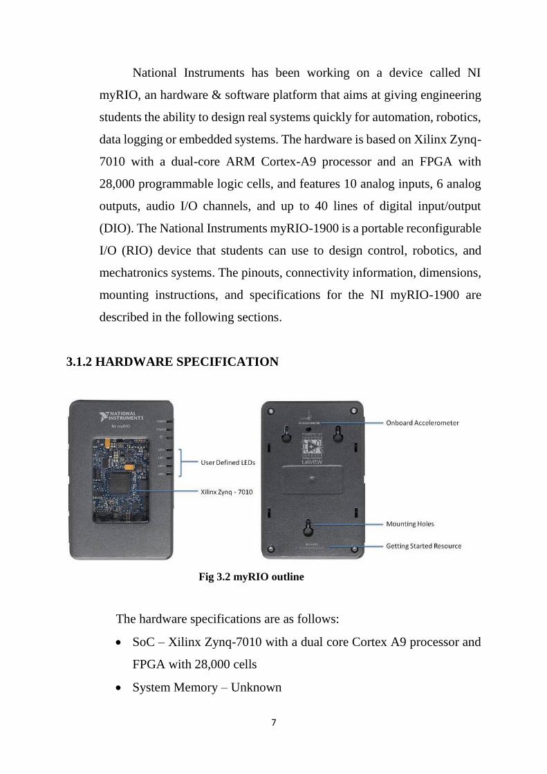
Fig 3.2 myRIO outline
The hardware specifications are as follows:
SoC – Xilinx Zynq-7010 with a dual core Cortex A9 processor and
FPGA with 28,000 cells
System Memory – Unknown
8
Storage – Unknown
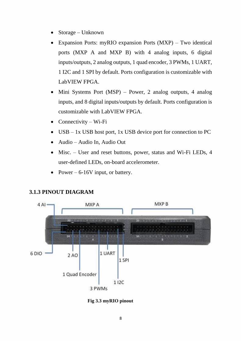
Expansion Ports: myRIO expansion Ports (MXP) – Two identical
ports (MXP A and MXP B) with 4 analog inputs, 6 digital
inputs/outputs, 2 analog outputs, 1 quad encoder, 3 PWMs, 1 UART,
1 I2C and 1 SPI by default. Ports configuration is customizable with
LabVIEW FPGA.
Mini Systems Port (MSP) – Power, 2 analog outputs, 4 analog
inputs, and 8 digital inputs/outputs by default. Ports configuration is
customizable with LabVIEW FPGA.
Connectivity – Wi-Fi
USB – 1x USB host port, 1x USB device port for connection to PC
Audio – Audio In, Audio Out
Misc. – User and reset buttons, power, status and Wi-Fi LEDs, 4
user-defined LEDs, on-board accelerometer.
Power – 6-16V input, or battery.
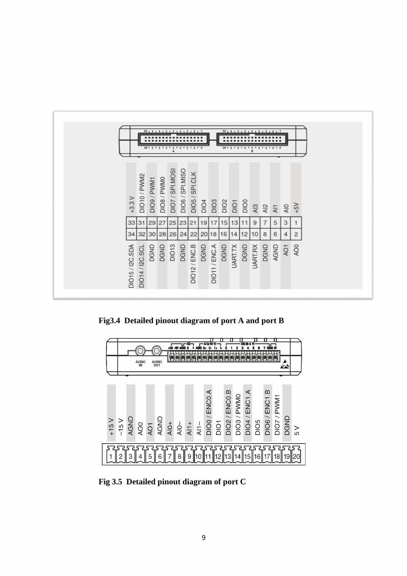
3.1.3 PINOUT DIAGRAM
Fig 3.3 myRIO pinout
9
Fig3.4 Detailed pinout diagram of port A and port B
Fig 3.5 Detailed pinout diagram of port C
10
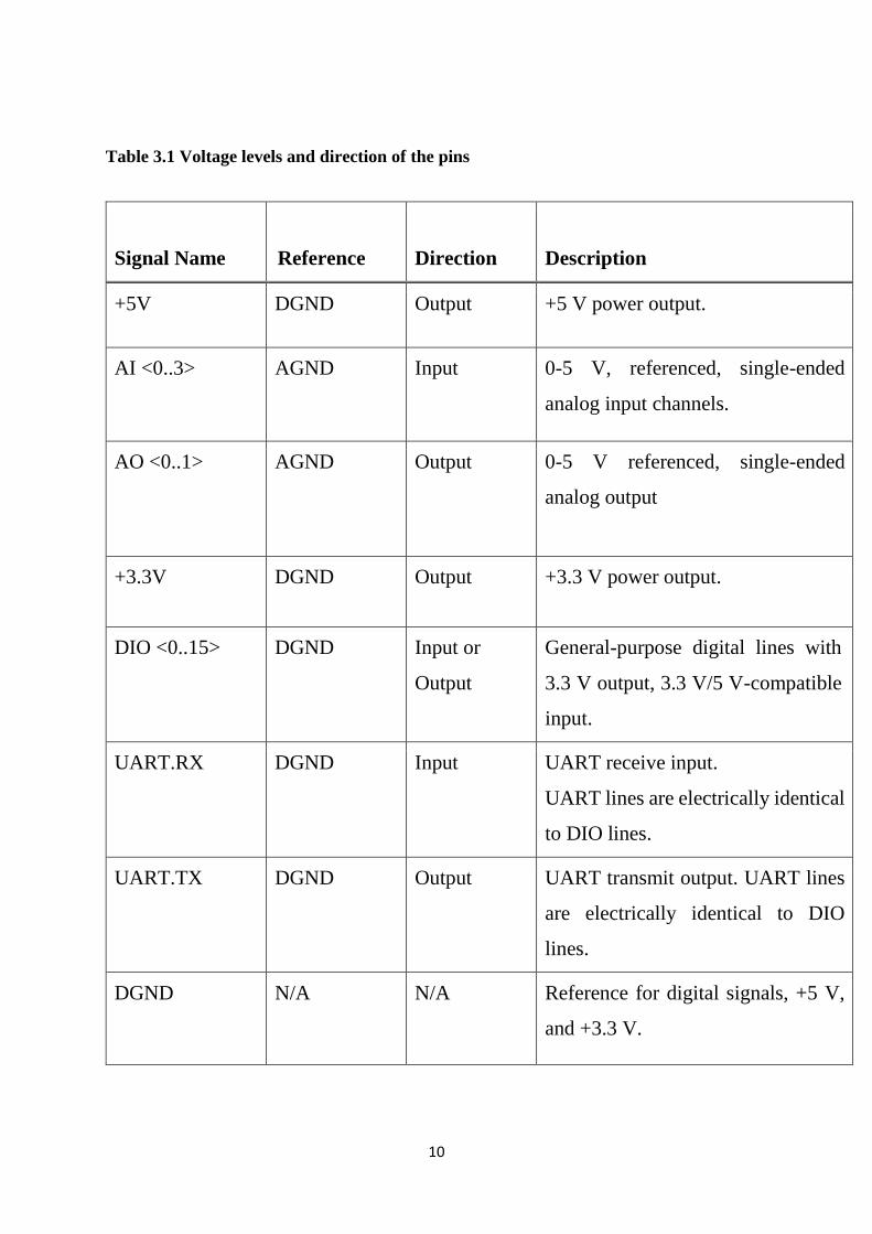
Table 3.1 Voltage levels and direction of the pins
Signal Name
Reference
Direction
Description
+5V DGND Output +5 V power output.
AI <0..3> AGND Input 0-5 V, referenced, single-ended
analog input channels.
AO <0..1> AGND Output 0-5 V referenced, single-ended
analog output
+3.3V DGND Output +3.3 V power output.
DIO <0..15> DGND Input or
Output
General-purpose digital lines with
3.3 V output, 3.3 V/5 V-compatible
input.
UART.RX DGND Input UART receive input.
UART lines are electrically identical
to DIO lines.
UART.TX DGND Output UART transmit output. UART lines
are electrically identical to DIO
lines.
DGND N/A N/A Reference for digital signals, +5 V,
and +3.3 V.
11
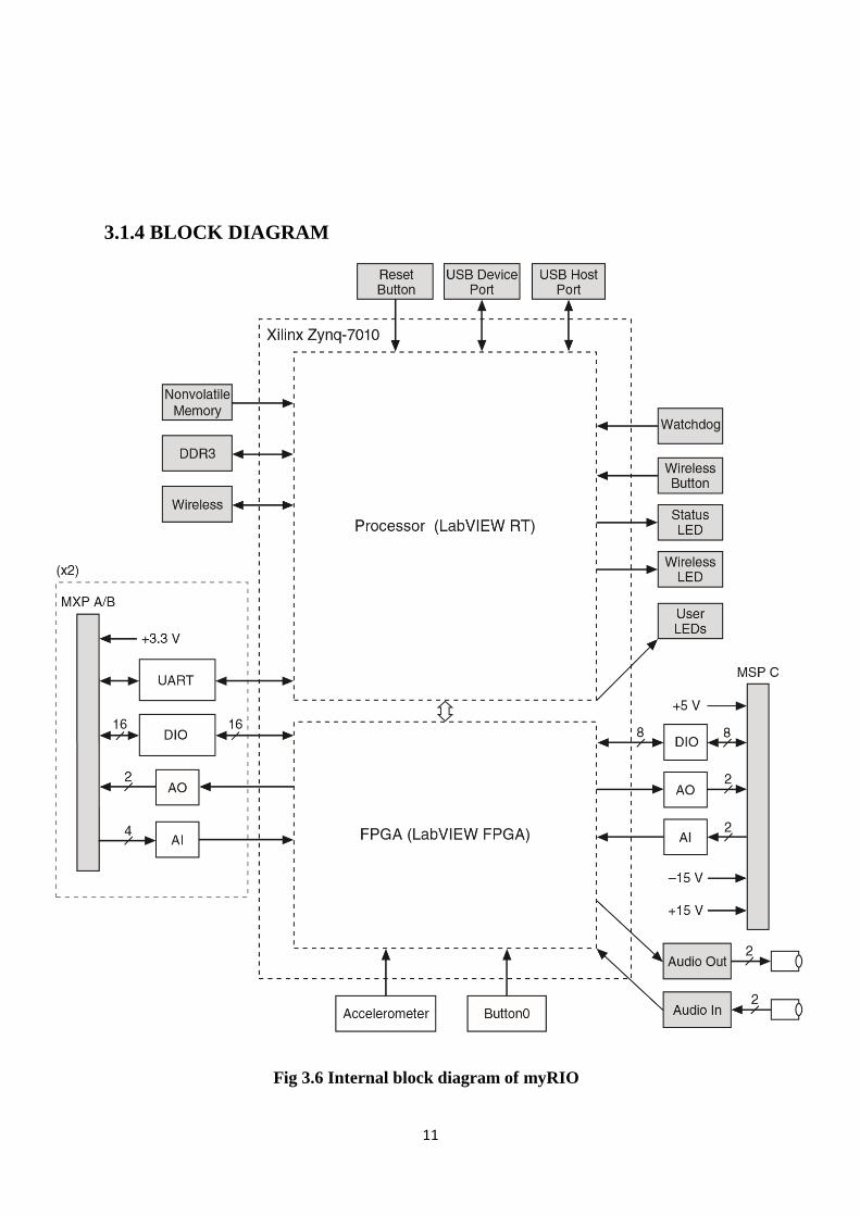
3.1.4 BLOCK DIAGRAM
Fig 3.6 Internal block diagram of myRIO
12
NI myRIO-1900 Expansion Port (MXP) connectors A and B carry
identical sets of signals. The signals are distinguished in software by the
connector name, as in Connector A/DIO1 and Connector B/DIO1.
3.1.5 ANALOG INPUT CHANNELS
The NI myRIO-1900 has analog input channels on myRIO
Expansion Port (MXP) connectors A and B, Mini System Port (MSP)
connector C, and a stereo audio input connector. The analog inputs are
multiplexed to a single analog-to-digital converter (ADC) that samples all
channels. MXP connectors A and B have four single-ended analog input
channels per connector, AI0-AI3, which you can use to measure 0-5 V
signals. MSP connector C has two high-impedance, differential analog
input channels, AI0 and AI1, which you can use to measure signals up to
±10 V. The audio inputs are left and right stereo line-level inputs with a
±2.5 V full-scale range.
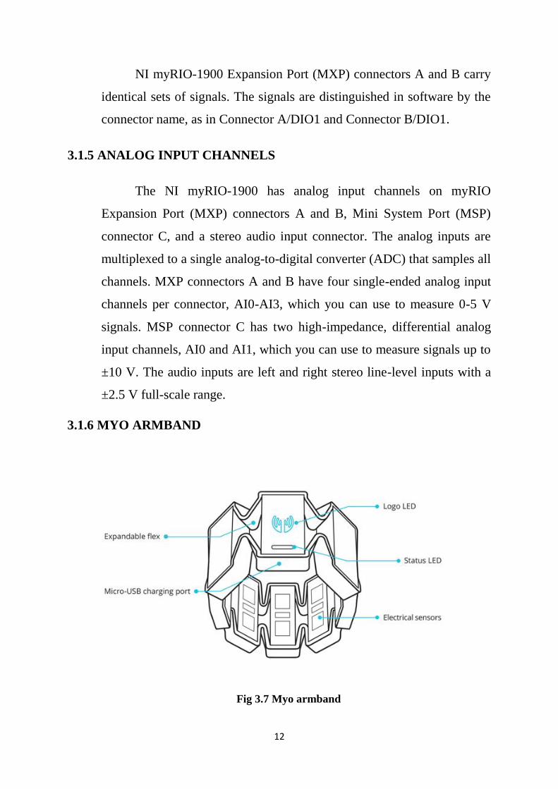
3.1.6 MYO ARMBAND
Fig 3.7 Myo armband
13
The Myo armband is a gesture recognition device, worn on the wrist
and manufactured by Thalmic Labs. The Myo enables the user to control
technology wirelessly using various wrist and forearm motions. It uses a
set of electromyography (EMG) sensors that sense electrical activity in the
forearm, combined with a gyroscope, accelerometer and magnetometer to
recognize gestures. The Myo can be used to control video games,
presentations, music and visual entertainment. It differs from the Leap
Motion device as it is worn rather than a 3D array of cameras that sense
motion in the environment. The eight segments of expandable
casing house the Myo armband's components and are connected using
stretchable material that allows them to expand and contract relative to
each other, so that the Myo armband can comfortably fit each user's unique
physiology. The electrical sensors measure electrical signals traveling
across the user's arm, which the Myo armband translates into poses and
gestures. The USB charging port allows you to charge the Myo armband's
internal battery using a USB power adapter or a conventional USB port on
a computer. The logo LED shows the sync state of the Myo armband. It
pulses when the Myo armband is not synced. The LED becomes solid
when you perform the Sync Gesture successfully and the Myo armband is
synced to your arm. The status LED shows the current state of the Myo
armband. It lights up in blue once the Myo armband is connected to a
device.
14
The Myo armband is connected to a device (e.g. a computer, tablet,
or smartphone) using Bluetooth 4.0 Low Energy. The SDK takes care of
all of the low level details related to Bluetooth connections and data
transmission. At its core, the Myo armband provides two kinds of data to
an application, spatial data and gestural data. Spatial data informs the
application about the orientation and movement of the user's arm. The Myo
SDK provides two kinds of spatial data:
An orientation represents which way the Myo armband is
pointed. In the SDK this orientation is provided as a quaternion
that can be converted to other representations, like a rotation
matrix or Euler angles.
An acceleration vector represents the acceleration the Myo
armband is undergoing at any given time. The SDK provides this
as a three-dimensional vector.
Gestural data tells the application what the user is doing with their
hands. The Myo SDK provides gestural data in the form of one of several
preset poses, which represent a particular configuration of the user's hand.
For example, one pose represents the hand making a fist, while another
represents the hand being at rest with an open palm. The Myo armband
provides information about which arm it is being worn on and which way
it is oriented - with the positive x axis facing either the wrist or elbow. This
is determined by a Sync Gesture performed upon putting it on. The Myo
armband similarly detects when it has been removed from the arm. An
application can provide feedback to the wearer of the Myo armband by
issuing a vibration command. This causes the Myo armband to vibrate in
a way that is both audible and sensed through touch.
15
3.1.7 USE OF MYO
Myo band will be used to vary the parameters like ball speed, spin,
type and direction of the delivery. Myo will be connected to myRIO via
Bluetooth. The gestures recognized by Myo will be programmed for the
above various desired functions. This is done to reduce the amount of user
interaction with the system physically.
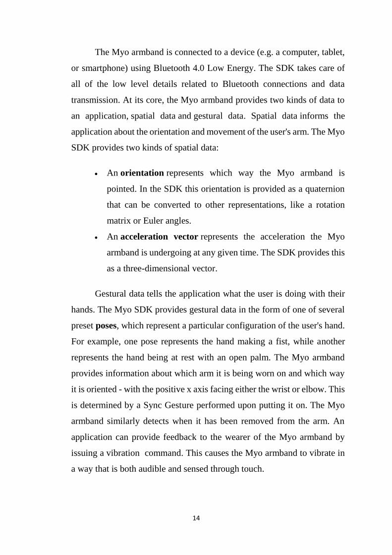
3.1.8 HC-06 BLUETOOTH MODULE DESCRIPTION
Fig 3.8 HC-06 Bluetooth module
This Bluetooth module can easily achieve serial wireless data
transmission. Its operating frequency is among the most popular 2.4GHz
ISM frequency band (i.e. Industrial, scientific and medical). It adopts
Bluetooth 2.0+EDR standard. In Bluetooth 2.0, signal transmit time of
different devices stands at a 0.5 seconds interval so that the workload of
Bluetooth chip can be reduced substantially and more sleeping time can be
16
saved for Bluetooth. This module is set with serial interface, which is easy
to use and simplifies the overall design/development cycle.
3.1.9 HC-06 SPECIFICATIONS
Bluetooth protocol: Bluetooth 2.0+ EDR standard
USB protocol: USB v1.1/2.0
Operating frequency: 2.4GHz ISM frequency band
Modulation mode: Gauss frequency Shift Keying
Transmit power: ≤ 4dBm, second stage
Sensitivity: ≤-84dBm at 0.1% Bit Error Rate
Transmission speed: 2.1Mbps(Max)/160 kbps(Asynchronous)
1Mbps/1Mbps(Synchronous)
Safety feature: Authentication and encryption
Supported configuration: Bluetooth serial port (major and minor)
Supply Voltage: +3.3 VDC 50mA
Operating temperature: -20 to 55℃
Size: 36.5*16mm
Weight: 4g
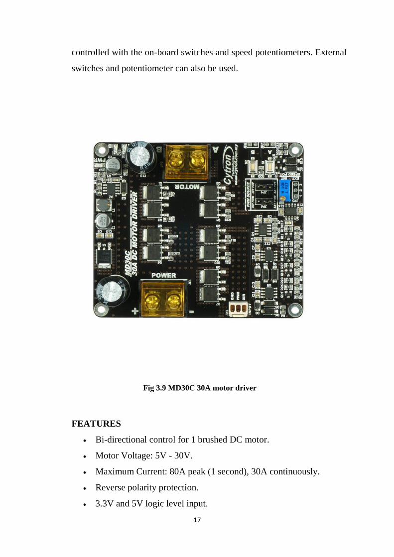
3.1.10 30A DC MOTOR DRIVER – MD30C
MD30C is the successor of MD30B which is designed to drive
medium to high power brushed DC motor with current capacity up to 80A
peak and 30A continuously. Fully NMOS design not only provides faster
switching time, it is also more efficient and no heatsink or fan is required.
Besides that, MD30C also incorporates some user friendly features
such as reverse polarity protection and on-board PWM generator which
allows it to operate without host controller. The motor can simply be
17
controlled with the on-board switches and speed potentiometers. External
switches and potentiometer can also be used.
Fig 3.9 MD30C 30A motor driver
FEATURES
Bi-directional control for 1 brushed DC motor.
Motor Voltage: 5V - 30V.
Maximum Current: 80A peak (1 second), 30A continuously.
Reverse polarity protection.
3.3V and 5V logic level input.
18
Fully NMOS H-Bridge for better efficiency and no heat sink is
required.
Speed control PWM frequency up to 20 KHz (Actual output
frequency is same as input frequency when external PWM is
selected).
On-board PWM generator with switches and potentiometer for
standalone operation.
Support both locked-antiphase and sign-magnitude for external
PWM operation.
3.2 MECHANICAL STRUCTURE
The base plate is the one which generally holds the entire structure.
The wheels are attached to the structure in order to help the system to attain
the motion towards the left or the right side of the court. The basic structure
which is held over the base plate is supported using the side frames. The
wheels rotate in opposite direction and the gap between them is slightly
less than the typical tennis ball diameter. The ball speed and spin is
controlled by controlling the speed of the DC motors which have a
maximum of 5200rpm. To give the ball direction, the frame must move in
two axis, lateral movement and Up-down movement. These movements
can be controlled with the help of wiper motors. For the up and down
movement there is a wiper motor to the frame with the help of the bearing
that in turn helps to move the frame up and down and in the case of the
lateral movement there is a wiper motor to the base plate where there are
two rotatable wheels that help to move the system which is at the back and
a wheel at the front to make the lateral movement. This in turn helps to
stabilize the system from moving from its initial position. And for the
19
power source for the motors, the testing is done with various options like
normal lead-acid battery and lithium-polymer.
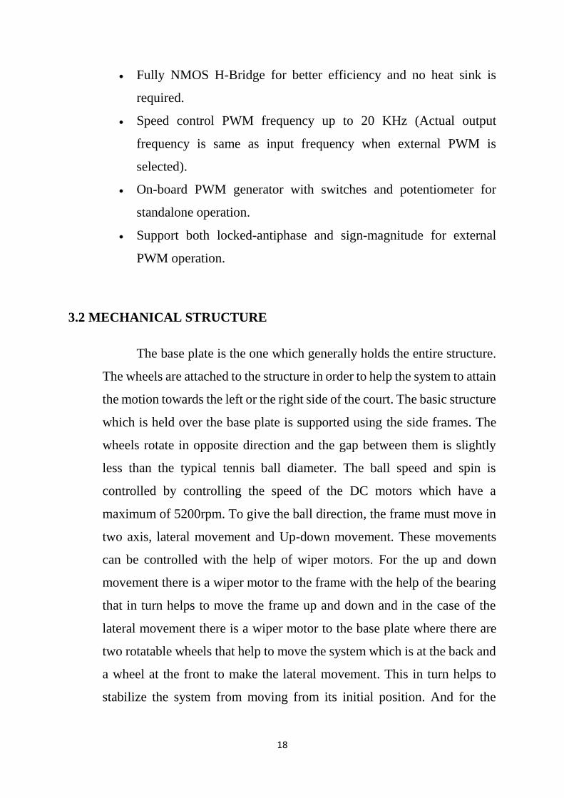
The basic structure was designed using Cryo cad software. The
design photos are attached below:
Fig 3.10 Design model 1
This is 3D model of the frame which is used for the tennis tutor
machine. The rollers are made of the foam material and the frames are
made of steel. There are aluminum based rounded frames attached to the
rollers to enhance the roller spin without inducing any imbalances while
the roller is spinning.
20
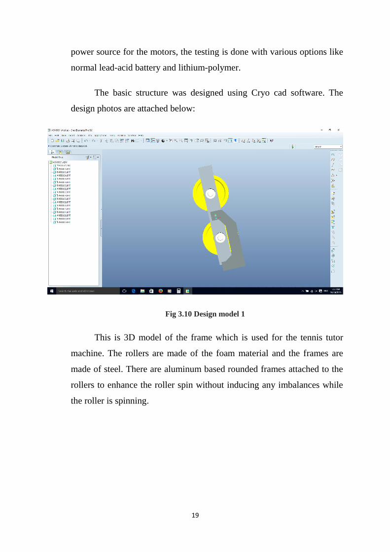
Fig3.11 Deign model 2
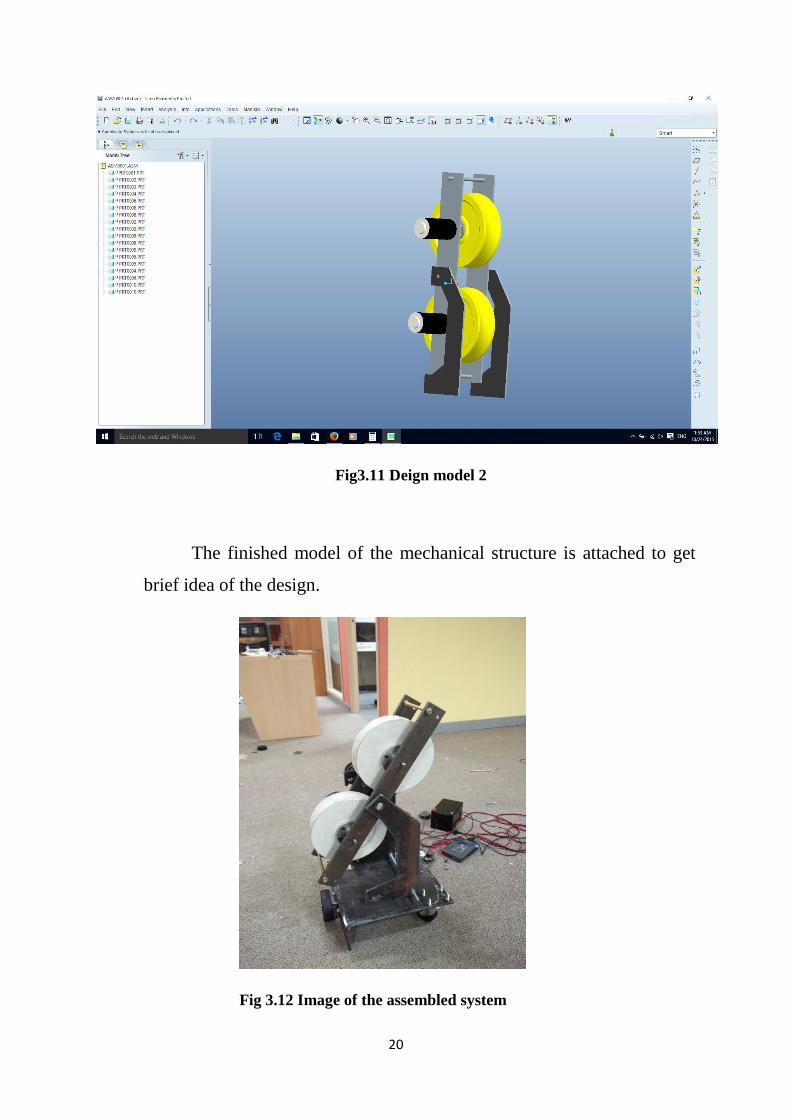
The finished model of the mechanical structure is attached to get
brief idea of the design.
Fig 3.12 Image of the assembled system
21
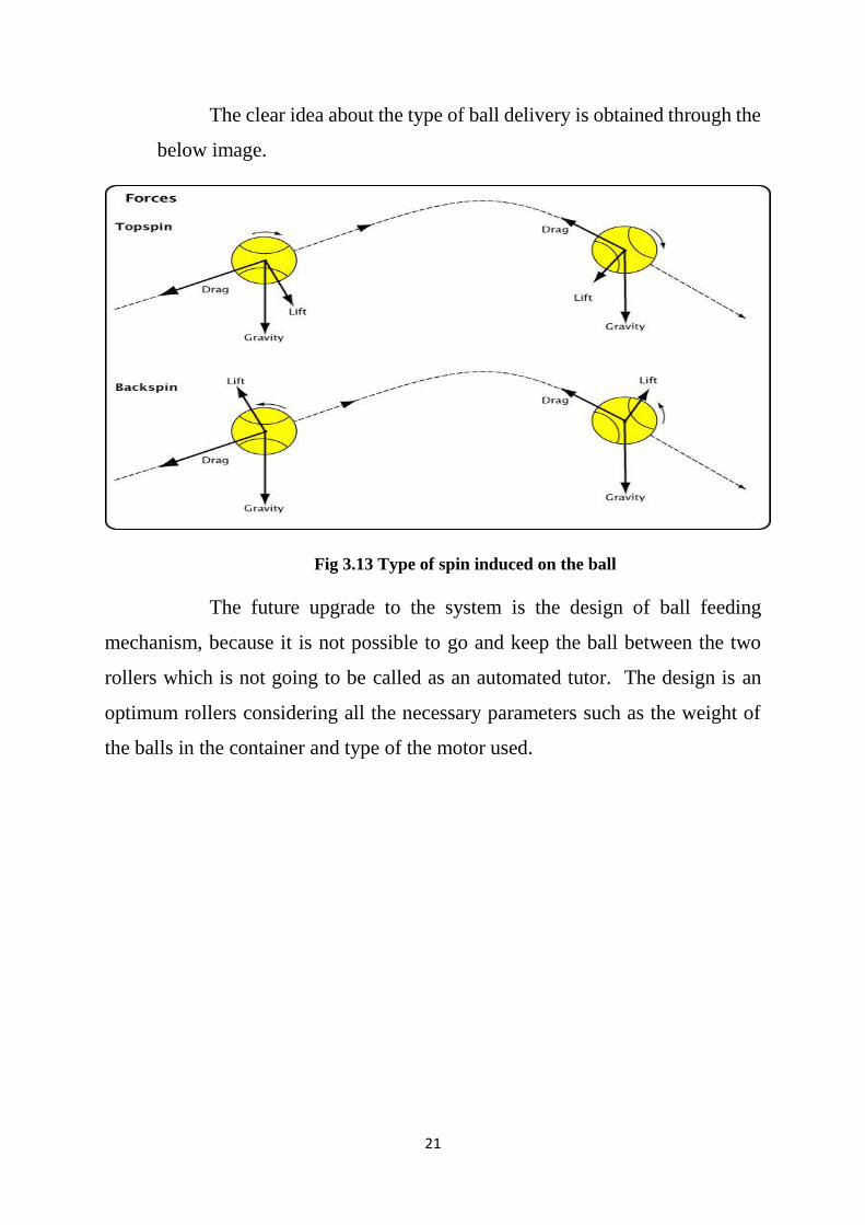
The clear idea about the type of ball delivery is obtained through the
below image.
Fig 3.13 Type of spin induced on the ball
The future upgrade to the system is the design of ball feeding
mechanism, because it is not possible to go and keep the ball between the two
rollers which is not going to be called as an automated tutor. The design is an
optimum rollers considering all the necessary parameters such as the weight of
the balls in the container and type of the motor used.
22
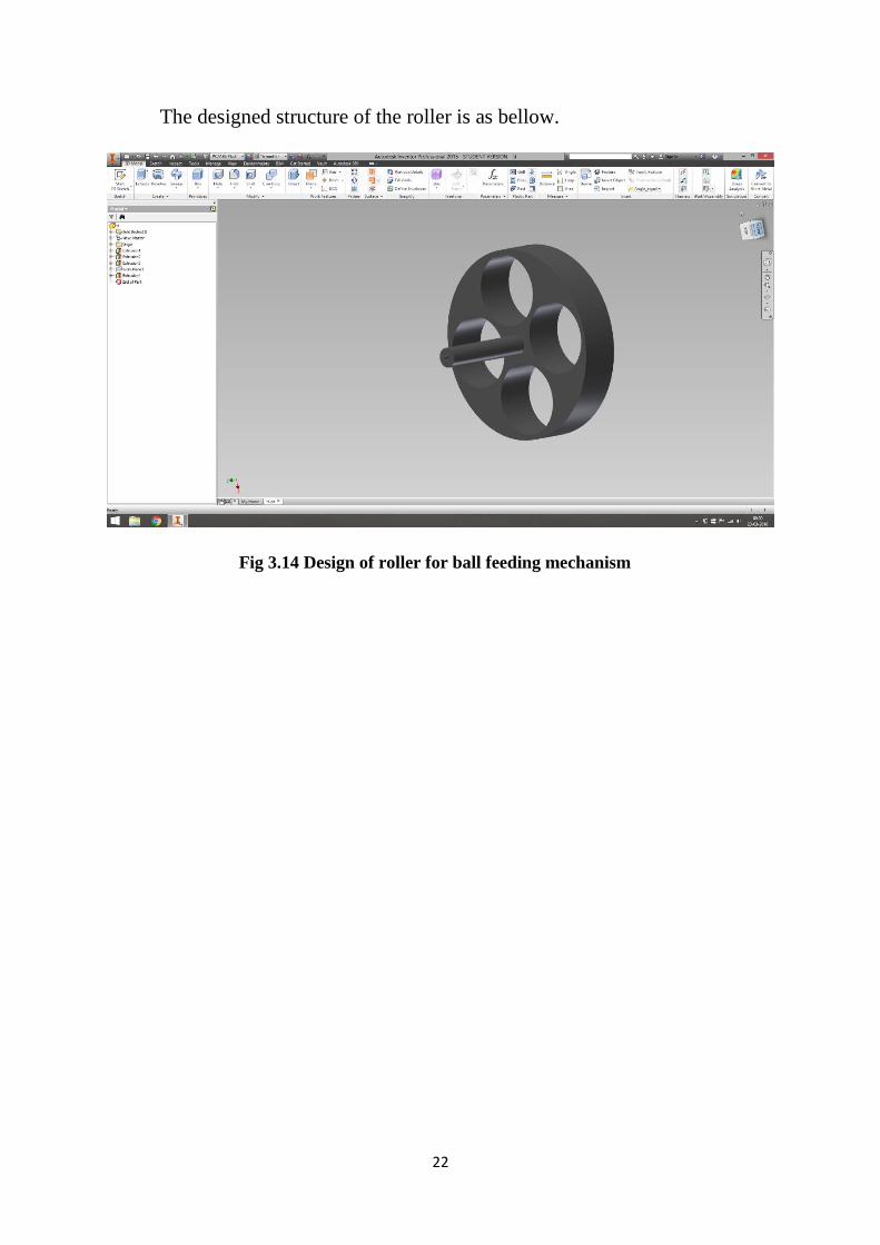
The designed structure of the roller is as bellow.
Fig 3.14 Design of roller for ball feeding mechanism

23
CHAPTER 4
24
4. SOFTWARE DESCRIPTION
The software section consists of two parts, one is programming the
myRIO using NI LabVIEW and other is developing an android application for
the remote control of the system.
4.1 NI LabVIEW
LabVIEW is an acronym for Laboratory Virtual Engineering
Workbench and it’s a system-design platform and development environment for
a visual programming. LabVIEW is commonly used for data acquisition,
instrument control and industrial automation on a variety of platform. This tool
is chosen because it suits the most for the tennis tutor.
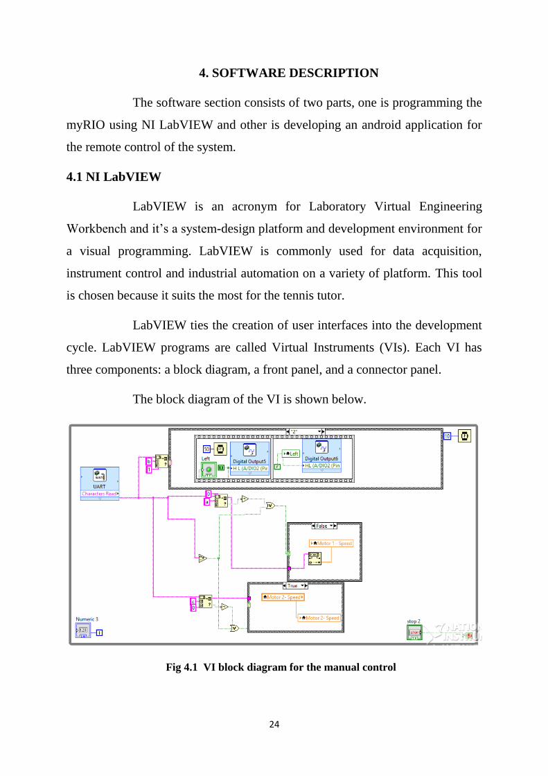
LabVIEW ties the creation of user interfaces into the development
cycle. LabVIEW programs are called Virtual Instruments (VIs). Each VI has
three components: a block diagram, a front panel, and a connector panel.
The block diagram of the VI is shown below.
Fig 4.1 VI block diagram for the manual control
25
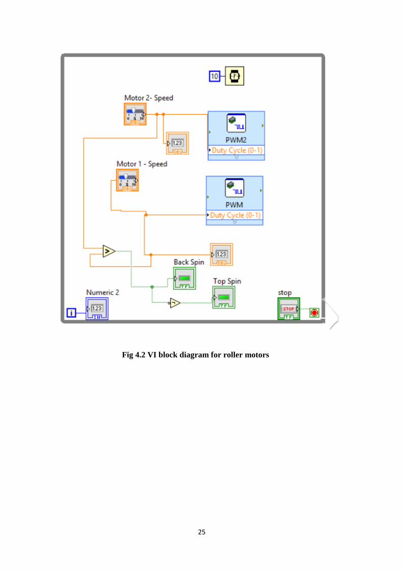
Fig 4.2 VI block diagram for roller motors
26
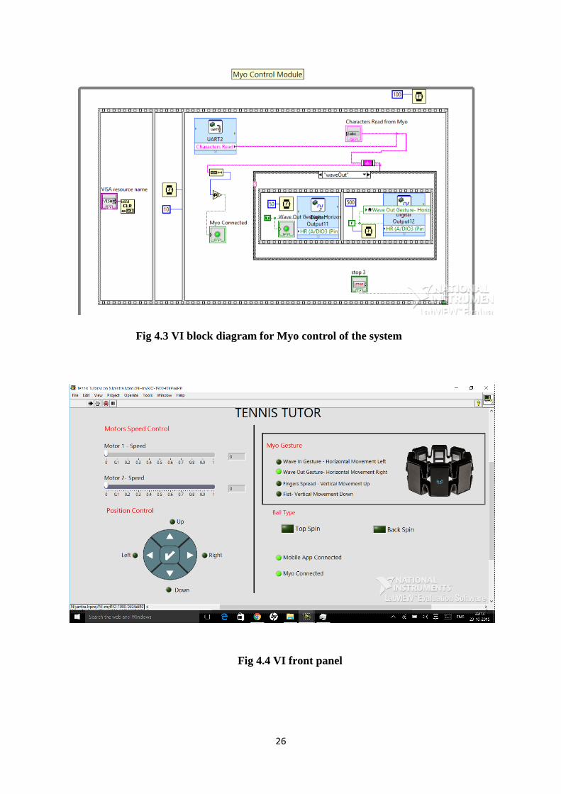
Fig 4.3 VI block diagram for Myo control of the system
Fig 4.4 VI front panel
27
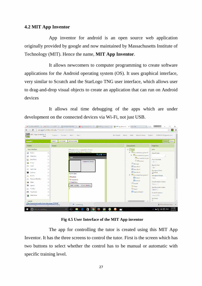
4.2 MIT App Inventor
App inventor for android is an open source web application
originally provided by google and now maintained by Massachusetts Institute of
Technology (MIT). Hence the name, MIT App Inventor.
It allows newcomers to computer programming to create software
applications for the Android operating system (OS). It uses graphical interface,
very similar to Scratch and the StarLogo TNG user interface, which allows user
to drag-and-drop visual objects to create an application that can run on Android
devices
It allows real time debugging of the apps which are under
development on the connected devices via Wi-Fi, not just USB.
Fig 4.5 User Interface of the MIT App inventor
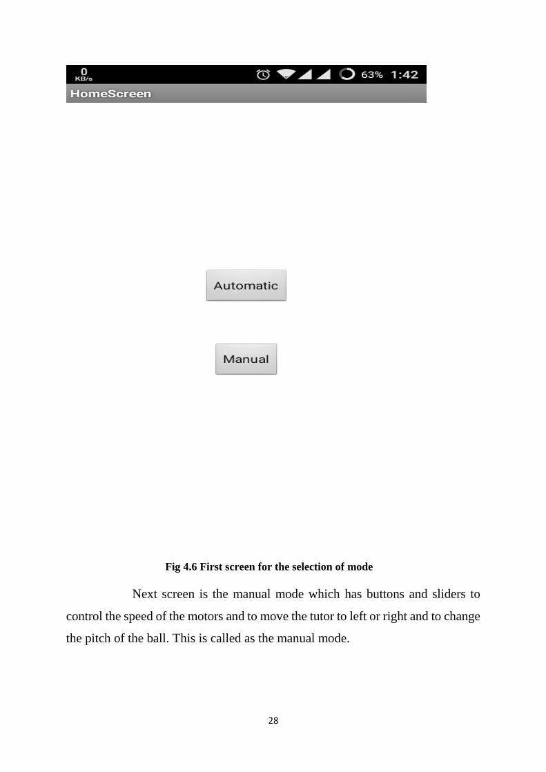
The app for controlling the tutor is created using this MIT App
Inventor. It has the three screens to control the tutor. First is the screen which has
two buttons to select whether the control has to be manual or automatic with
specific training level.
28
Fig 4.6 First screen for the selection of mode
Next screen is the manual mode which has buttons and sliders to
control the speed of the motors and to move the tutor to left or right and to change
the pitch of the ball. This is called as the manual mode.
29
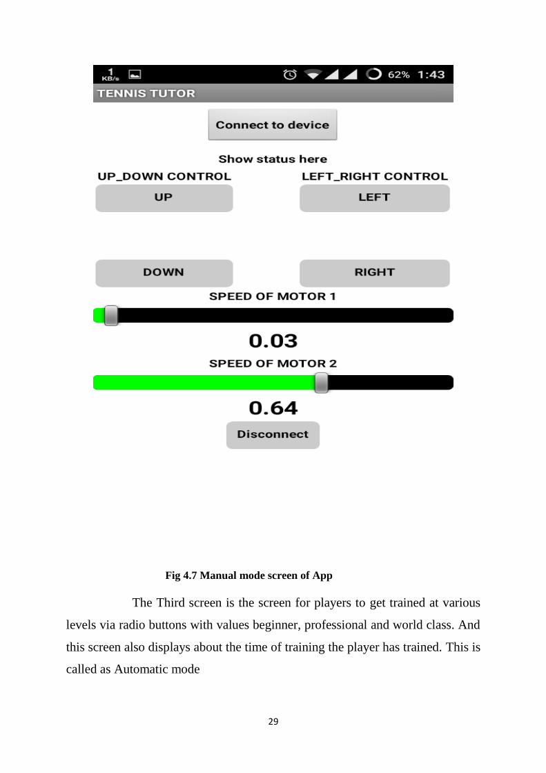
Fig 4.7 Manual mode screen of App
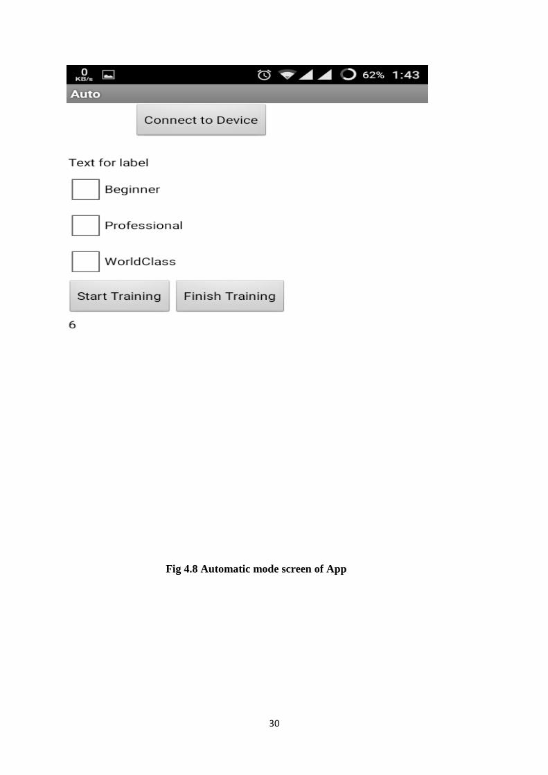
The Third screen is the screen for players to get trained at various
levels via radio buttons with values beginner, professional and world class. And
this screen also displays about the time of training the player has trained. This is
called as Automatic mode
30
Fig 4.8 Automatic mode screen of App

31
CHAPTER 5
32
5. WORKING PRINCIPLE
The MyRIO is going to act as the central console or the heart of the
embedded system. The MyRIO consists of pins to control the motors. So
this is mainly going to support our action. The inputs are obtained from the
Myo armband and also from the android app that is created for our tennis
tutor. The inputs are basically passed with help of the Bluetooth module
(HC-06).The MyRIO then takes the inputs and it varies the speed of the
corresponding motors .This is done with the help of the motor drivers. The
motor drivers decide the speed at which the roller should rotate. Thus the
speed of the roller is manually controlled in order to obtain the desired spin
on the ball that is played. The android app generally has the features to
change the speed of the motor and the direction of the ball throw which can
be given as inputs to the myRIO that executes the function
correspondingly. The Myo involves the use of gestures to give inputs to
the system. This system makes use of four gestures and using these four
gestures the various operations are made.

33
CHAPTER 6
34
6. COST ANALYSIS
The existing machine without any added features to the tutor except
for the ball throwing action costs about 699$(which is 46K approx. without
any taxes included).A fully automated machine which can only be remote
controlled or with physical contact with the machine costs about 1099-
3299 $ (which is from 75k-200k in Indian rupees). So from the above
analysis it clearly shows that it is beyond the money an average Indian can
spend on it. The machine that is built costs only about 50K at the maximum
with the full features embedded in it.

35
CHAPTER 7

36
7. CONCLUSION
The model which is presented helps to enhance the usability of a
product, satisfies the people who want to learn the sport and it involves a
wide variety of features embedded in it. This model turns out to be a very
economical and useful product to the people of our country.

37
CHAPTER 8
38
8. REFERENCE
1. Prince Manufacturing Co., Inc. (1980) “Propulsion device for tennis
balls and like spherical objects having an improved programmed
discharge of the oscillatory type”.
2. United States Machine Works, Inc. (1981) “System and apparatus for
program controlled delivery of game balls”.
3. Eriksen Willy M (1988) “Projector for projecting a tennis ball”
4. Braden Victor K (1989) “Automatic tennis feeding and serving
apparatus”
5. Werner Salansky (1992) “Ball-throwing device for tennis balls”
6. Mattel, Inc. (2003) “Ball launching apparatus”.
7. Unified Solutions, Inc. (2005) “Variable trajectory kit for a ball
pitching mechanism”.
8. Rachel Baurnel (2012) “Metered ball delivery”.
9. Master Pitching Machine, Inc. (1994) “Ball collection and distribution
apparatus”
10. Hurst H Edson (2014) “Tennis ball throwing machine”