Embed Size (px)
Citation preview
User Manual 1
confi
─ DVR ─
User Manual
Notice: This content is subject to be change without notice.
V1.0

User Manual 2
This symbol is intended to alert the user to the presence of unprotected “Dangerous voltage" within the product's enclosure that may be strong enough to cause a risk of electric shock.
This symbol is intended to alert the user to the presence of important operating and maintenance (servicing) in-structions in the literature accompanying the appliance.
WARNING
TO REDUCE THE RISK OF FIRE OR ELECTRIC SHOCK, DO NOT EXPOSE THIS APPLIANCE TO RAIN OR MOIS-TURE.
NOTE: This equipment has been tested
and found to comply with the limits for a
class digital device, pursuant to part 15 of
the FCC Rules. These limits are designed
to provide reasonable protection against
harmful interference when the equipment is
operated in a commercial environment.
This equipment generates, uses, and can
radiate radio frequency energy and, if not
installed and used in accordance with the
instruction manual, may cause harmful in-
terference to radio communications. Oper-
ation of this equipment in a residential area
is likely to cause harmful interference in
which case the user will be required to
correct the interference at his own expense.
Disposal of Old Electrical & Electronic Equipment (Applicable in the European Union and other European countries with separate collection systems)
This symbol on the product or on its packaging indicates that this product shall not be treated
as household waste. Instead it shall be handed over to the applicable collection point for the
recycling of electrical and electronic equipment. By ensuring this product is disposed of cor-
rectly, you will help prevent potential negative consequences for the environment and human
health, which could otherwise be caused by inappropriate waste handling of this product. The
recycling of materials will help to conserve natural resources. For more detailed information
about recycling of this product, please contact your local city office, your household waste
disposal service or the shop where you purchased the product.
Notice: Ghosting or fractured images may occur on the screen when there is a suddenly surge
or lightning stroke which cause damage on IC in the DVRs.

User Manual 3
User Manual
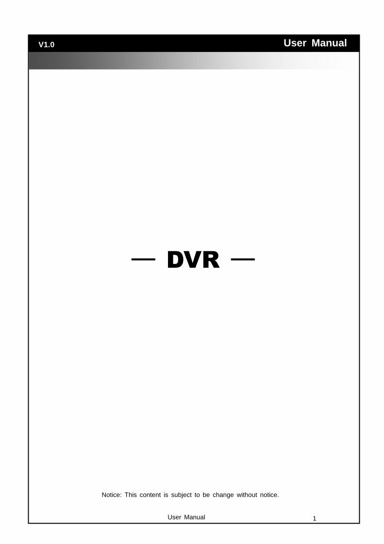
Display, right-click on the screen to evoke the main menu.
Single Screen CH1.CH2,CH3.CH4…..
User Manual 4
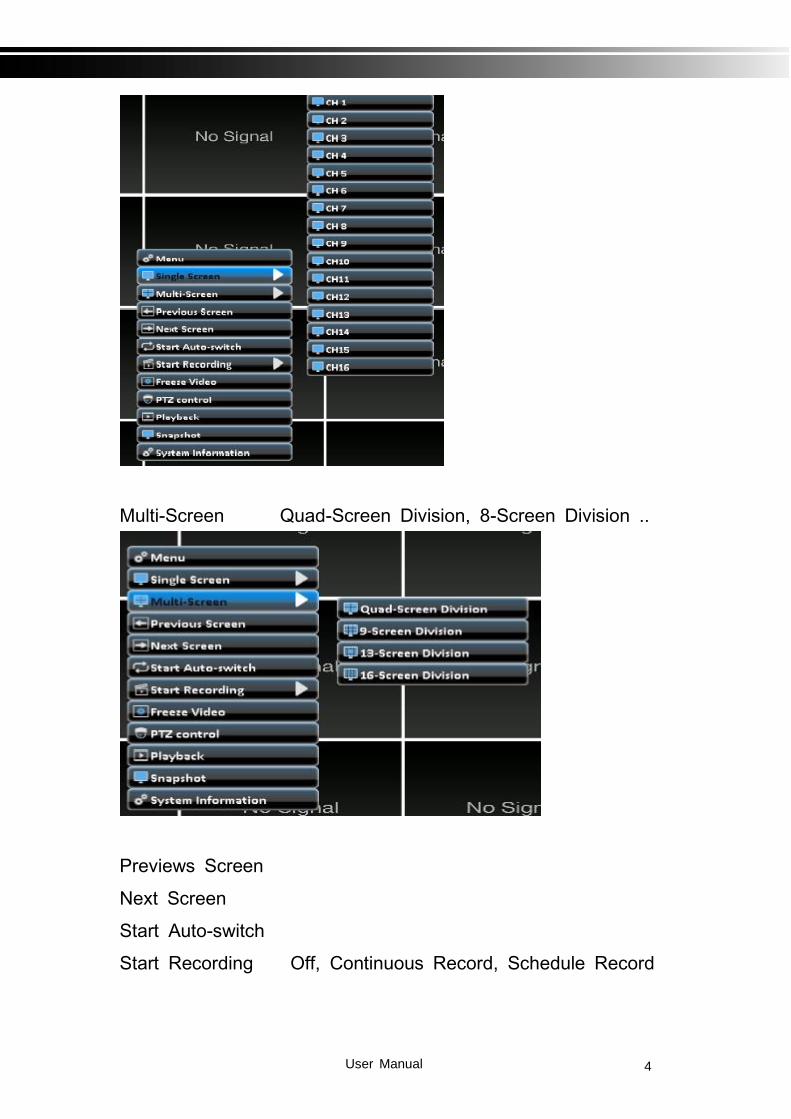
Multi-Screen Quad-Screen Division, 8-Screen Division ..
Previews Screen
Next Screen
Start Auto-switch
Start Recording Off, Continuous Record, Schedule Record

User Manual 5
Freeze Video
PTZ control
Playback
Menu::
Play Back: Playback by time
Export: Export record files by file on USB/DVD/Remote PC.
Manual: Manual Recording / Alarm
HDD: HDD Format and settings
Record: Record Schedule , parameters settings ... etc.
User Manual 6
Camera: Camera OSD , event, PTZ settings ... etc.
Configuration: System time / date, network, alarm settings ... et
c.
Maintenance: Upgrade, log, default etc.
Shutdown: Shutdown, reboot and logout.
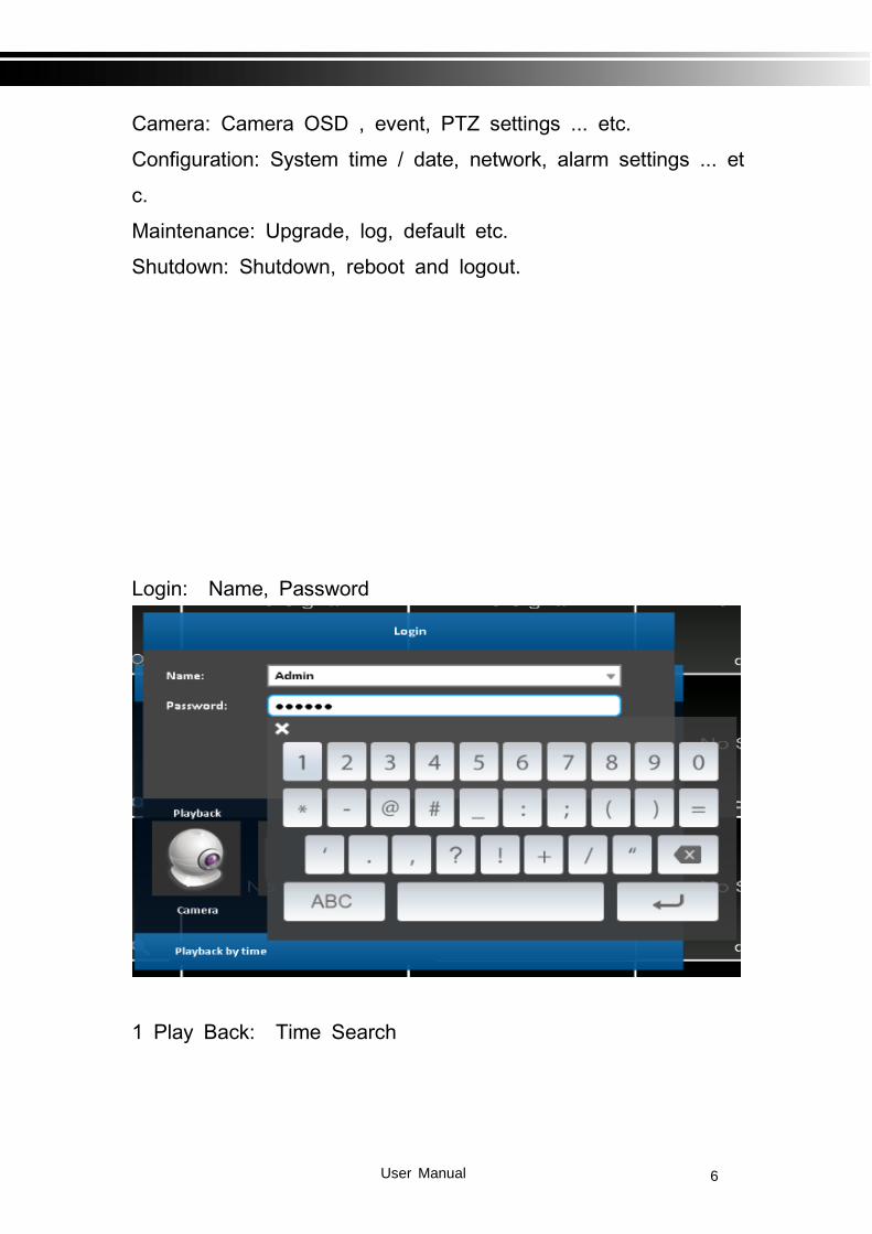
Login: Name, Password
1 Play Back: Time Search

User Manual 7
Time search can search for the specific time of recorded data
to playback. Note that dates with recording data are marked wi
th a blue box. System will start playing video of specified time
slot. Calendar will be shown by using mouse to click on “yea
r” and “month”.
Click “date” to display recording time of that specific date with
time bar. You can change time (hour/minute/second) or click o
n a specific pint of time bar by mouse then press “ok” . DVR
will playback the recorded data of the specific time.
Item Description
Playbackbut-
ton,startplay-bac.
Select playback time
by sliding the position
of the cursor to the
specified time. The

User Manual 8
timeline scale is 24
hours.
The blue chart rep-
resents available
video data.
2 xport: Export record files by file on USB/DVD/Remote PC.
User can backup recorded video data of a specified time frame.
The DVR can backup video data to either direct-attached stor
age, such as DVR or USB drive, or remote folder of a PC.
2-1 Selection
Item Description
From The start time of video data to be backed up
To The end time of video data to be backed up
Duration The time duration of backup file

User Manual 9
All It can select all channels or clear all selected chann
els to backup
Required Space Show the size of the backup file
2-2 Select Backup Device
Item Description
Backup Devi
ce
Select target device of backup (USB/DVD-RW/re
mote folder)
Status The status of target backup device
Free Space The available space in the target backup device.
(not available for
remote folder backup)
Backup Start backup operation.
Be sure to calculate the size of backup file BEF
ORE operating backup.
Do not unplug the USB device or turn off the DVR during the
backup process to avoid unrecoverable error.
User Manual 10
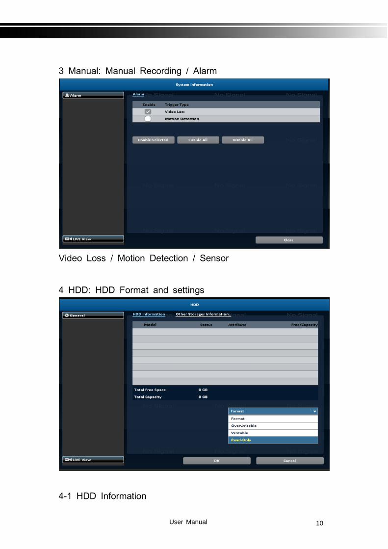
3 Manual: Manual Recording / Alarm
Video Loss / Motion Detection / Sensor
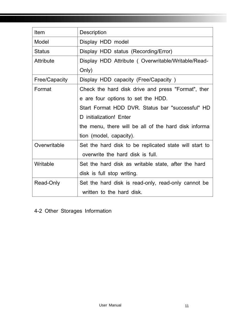
4 HDD: HDD Format and settings
4-1 HDD Information
User Manual 11
Item Description
Model Display HDD model
Status Display HDD status (Recording/Error)
Attribute Display HDD Attribute ( Overwritable/Writable/Read-
Only)
Free/Capacity Display HDD capacity (Free/Capacity )
Format Check the hard disk drive and press "Format", ther
e are four options to set the HDD.
Start Format HDD DVR. Status bar "successful" HD
D initialization! Enter
the menu, there will be all of the hard disk informa
tion (model, capacity).
Overwritable Set the hard disk to be replicated state will start to
overwrite the hard disk is full.
Writable Set the hard disk as writable state, after the hard
disk is full stop writing.
Read-Only Set the hard disk is read-only, read-only cannot be
written to the hard disk.
4-2 Other Storages Information

User Manual 12
4-2-1 USB Flash Derive Setup
Item Description
Model Display USB flash drive model
Free/Capacity Display USB flash drive capacity (Free/Capacity )
4-2-2 DVD-RW Setup
Item Description
Model Display DVR-RW model
Media Type Display disk type
Free/Capacity Display DVR-RW capacity (Free/Capacity )
5 Record: Record Schedule , parameters settings ... Etc.
5-1 Schedule Recording

User Manual 13
Schedule recording can configure recording time by days of a
week and hour.
With the A, B, C, D four settings, users can set different recor
ding scheme according to different configuration needs. In the
day and time grid map, select the schedule time zone, and the
n press A, B, C, D one of the buttons to specify the video set
tings.
5-2 Parameters

User Manual 14
Item Description
Camera Set Camera
Record Enable / Disable recording for this channel
(Continus & Event)
Resolution Recording resolution selection
Video Quality Recording quality, from 10 to 100. The larger
number means the better quality
Frame Rate Select recording frame rate, from 1 to 30
Record Audio Enable / Disable recording audio
Pre-record Set the record seconds before the event, from
0 to 10.
Post-record Set the playback seconds after the event, from
0 to 10

User Manual 15
5-3 Holiday Configuration
The number of holiday is up to 50. When the time comes to the
specified holidays, the DVR will start recording according to holiday
configuration.
Since holidays are different by different country and region, users
can setup holidays according to user needs.

User Manual 16
6 Camera: Camera OSD , event, PTZ settings ... Etc.
6-1 OSD
Item Description
Name Channel name
Timestamp Click on the blue screen to set position of the

User Manual 17
timestamp.
6-2 Image Setting
Item Description
Image
Infrared Cutoff Filter
BLC
DeNoise
Exposure
WDR
DIS
AWB
Defog
MirrorMode
6-3 PTZ

User Manual 18
6-3-1 Table-2 Setup description
Item Description
Enable Click the box to Enable/Disable PTZ function.
Protocol Set up the protocol of PTZ cam. The supported
protocol are: PELCO-D、PELCO-P、Merit LiLin
1、Merit LiLin 2、SAMSUNG、LG-MultixE
PTZ ID Set up PTZ ID. The valid ID value is from 0 to
255.
Baud Rate Select Baud Rate of PTZ control protocol from
2400, 4800, 9600,19200
6-3-2 Table-2 Function description
Item Description

User Manual 19
ZOOM. Press + / - or move the slider to
adjust the zoom level.
FOCUS. Press + / - or move the slider
adjust the PTZ focus
IRIS. Press + / - or move the slider to ad-
just the PTZ iris
Press left and right arrow keys to move
the camera to the preset locations, and
then press to set current camera loca-
tion to default point.
Press left and right arrow keys to move
the camera to the preset locations, and
then press to change the camera to
next preset point.
Rotate Video Make the display upside down
6-4 Motion Detection

User Manual 20
6-4-1 Motion Setup
The motion detection has been divided into 22 x18 grids. The
default detection area is full screen. The screen is marked in
transparent for detection area and grey for
disabled area of motion detection.
Item Description
CH01~ CH4 / CH8
/ CH16....
Selected channel motion detection function。
Enable Enable / Disable the motion detection func-
tion of this channel
Sensitivity The sensitivity value is from 0 to 100. The
higher value means higher sensitivity.
Motion Area Enter to setup motion detection area

User Manual 21
Alarm Enable or Unable Alarm
Enable All Region Select entire screen as detection area.
Disable All Region Deselect entire detection area.
Trigger Setting Popup Channel
6-5 Privacy Mask
Item Description
CH01~ CH4 / CH8
/ CH16....
Selected channel for Mask.
6-6 Video Loss

User Manual 22
6-6-1 Alarm setting
Item Description
CH01~ CH4 / CH8
/ CH16....
Selected channel Alarm function。
Enable Enable / Disable the Alarm function of this
channel
6-6-2 Trigger Setting
Popup
In the live mode, if video loss of a channel is
detected, it will pop up the channel full
screen. You can specify a warning window
display, 1: the main screen, 2: the second
screen.*1
Popup Channel When an event occurs, pop up the specified

User Manual 23
channel.
6-7 Maintenance
6-8 Information
6-9 IVS
User Manual 24
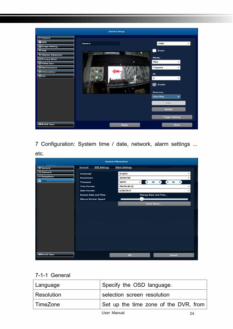
7 Configuration: System time / date, network, alarm settings ...
etc.
7-1-1 General
Language Specify the OSD language.
Resolution selection screen resolution
TimeZone Set up the time zone of the DVR, from

User Manual 25
GMT-13~GMT+ 13
Date Format / Time For
mat
MM-DD-YY/DD-MM-YY/YY-MM-DD AM
PM xx:xx:xx
System Date and Time Setup date and time of the DVR.
Mouse Pointer Speed Setup the mouse cursor speed. The rig
ht side of the slider means faster mou
se speed. (Only valid for local configur
ation)
7-1-2 DST Setting

User Manual 26
Daylight Saving Time Setup
Item Description
Beginning Setup the beginning time of Daylight Saving
Time.
Ending Setup the ending time of Daylight Saving
Time.
7-1-3 More Setting
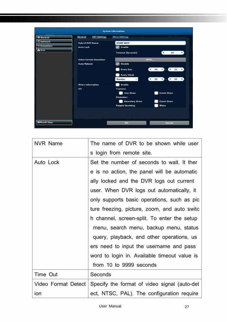
User Manual 27
NVR Name The name of DVR to be shown while user
s login from remote site.
Auto Lock Set the number of seconds to wait. It ther
e is no action, the panel will be automatic
ally locked and the DVR logs out current
user. When DVR logs out automatically, it
only supports basic operations, such as pic
ture freezing, picture, zoom, and auto switc
h channel, screen-split. To enter the setup
menu, search menu, backup menu, status
query, playback, and other operations, us
ers need to input the username and pass
word to login in. Available timeout value is
from 10 to 9999 seconds
Time Out Seconds
Video Format Detect
ion
Specify the format of video signal (auto-det
ect, NTSC, PAL). The configuration require

User Manual 28
s DVR reboot to take effect
7-1-3-1 Auto Reboot
Item Description
Disable Enable / Disable Auto Reboot.
Every day Setup the time of daily auto-reboot.
Every Week Setup the time of weekly auto-reboot.
7-1-4 IPCam Information
7-1-5 IVS
7-2 NetWork
There are five ways to connect to the network.
7-2-1-1 DHCP Setup
When DHCP is selected, IP address will be assigned by DHCP
server automatically.
Notice: The IP address shown in this page is not the IP addre
ss obtained from the DHCP server. The IP obtained from the
DHCP server is shown in the System Information Page.

User Manual 29
7-2-1-2 Virtual Network Interface
7-2-2 Static IP Setup
Setup Static IP for network connection, the following informatio
n is required.

User Manual 30
Item Description
Enable Enable / Disable Static IP function。
IP Enter the static IP address provided by ISP
Subnet
Mask
Enter IP address of Subnet Mask provided by ISP
Gateway Enter IP address of the Gateway provided by ISP
DNS Enter the DNS address provided by ISP.
(Note: The correct DNS address must be entered for
DDNS function).
7-2-3 PPPoE Setup
Select PPPoE for network connection, the following information
is required.
Item Description
User Manual 31
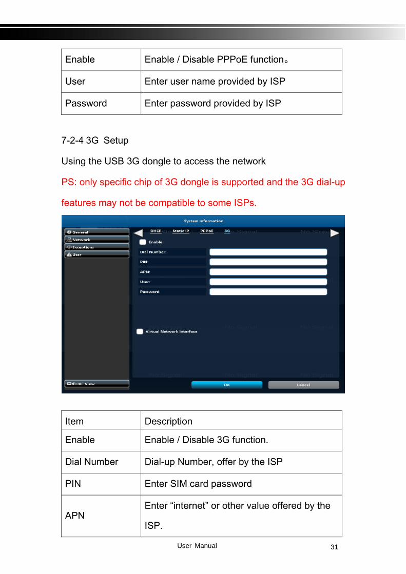
Enable Enable / Disable PPPoE function。
User Enter user name provided by ISP
Password Enter password provided by ISP
7-2-4 3G Setup
Using the USB 3G dongle to access the network
PS: only specific chip of 3G dongle is supported and the 3G dial-up
features may not be compatible to some ISPs.
Item Description
Enable Enable / Disable 3G function.
Dial Number Dial-up Number, offer by the ISP
PIN Enter SIM card password
APN Enter “internet” or other value offered by the
ISP.

User Manual 32
User Enter ISP username
Password Enter ISP password
7-3 Alarm
7-3-1 Alarm Status
Item Description
Enable Enable/Disable sensor
Polarity
N.C: Sensor has not been triggered. When
connected, sensor will be turned on
N.O: Sensor has been triggered. When
connected, sensor status will be turned off
7-3-2 Alarm Input

User Manual 33
7-3-3 Alarm Output
7-4 Exceptions
When the system event occurs, give a notice or warning accor
ding to the settings of relay, buzzer, and receiver. If the buzze
r box is checked, the buzzer continually beeps for only errors r
elated to the video (such as hard drives can’t write or not inst
all the hard drive). The buzzer does not beep when other syst
em events, such as login, log out or boot, etc., occurs.

User Manual 34
Item Description
Buzzer Specify whether the buzzer beeps when a
recording error occurs.
Relay Specify the relay to be evoked when an
event occurs.
Mail To Specify the receiver of e-mail setup
7-5 User
You can set the user password and permissions of 10 user accounts
(1 admin + 10 users). These different accounts gives users different
permissions of DVR features.

User Manual 35
Item Description
Enable Check to activate the user’s account.
Expire Set the expire date of the user account
Name Set up the username
Password Set up the password. The password can be mixed
of letters and numbers and is case-sensitive.

User Manual 36
e-Mail Set up user email
8 Maintenance: Upgrade, log, default etc.
8-1-1 Device Info.
8-1-2 Camera Info.

User Manual 37
8-1-3 Record Info.
8-1-4 Network Info.
Item Description
IP DVR IP address

User Manual 38
If there is no network connection, it will show
"Network is not connected.
MAC The DVR MAC address
8-1-5 HDD Info.
Item Description
Recording
Scheme Display installed HDD recording type
Model Display installed HDD model
Status Display installed HDD recording status
Free Space Display installed HDD Free space
Capacity Display installed HDD capacity
8-2 Log Information
The DVR logs events automatically. The event list shows the l
ogged events, event type, event detail, event filter (criteria), an

User Manual 39
d page number of the event list. If the event video is logged, t
here is a gray video symbol "►" on the left of the event. Move
the cursor to event line and press "ENTER", or double-click m
ouse button, DVR playback this record video related to the eve
nt.
8-2-1 Log Search
The number of event is up to thousands, therefore, to set "sea
rch criteria" to facilitate rapid classification of events. If the che
ckbox of start time and end time is checked, the event list will
only display the events within the specific time slot. If the use
r unchecks some events and press the "OK ", the lists will onl
y shows checked events. If you uncheck the channels, the eve
nt list will filter out unchecked the channels.
8-2-2 Log Proc.

User Manual 40
Item Description
Export Logs Save DVR system log to a USB flash drive or a
remote PC.
Clear Logs Clear all DVR system log.
8-3 Import / Export

User Manual 41
Item Description
Export Config-
uration
Export DVR configuration to a USB flash drive
or a remote PC.
Import Config-
uration
Import configuration from a USB flash drive or a
remote PC to DVR.
8-4 Upgrade

User Manual 42
Item Description
Upgrade
Firmware
Upgrade DVR firmware through a USB drive.
Please stop recording and backup DVR con-
figuration before upgrading
System will reboot automatically when the up-
grade is done.
8-5 Default

User Manual 43
Item Description
Reset Config-
uration Reset system configuration.
8-6 HDD Detect
8-6-1 S.M.A.R.T Setting

User Manual 44
9 Shutdown: Shutdown, reboot and logout.

User Manual 45
10 APP Software Connection (Android for example):
1. Go “Google Play” or “Android Market”(China) or APP store (iOS) to download the “Swift Connection”
2. Press the “+” key in the upper right corner to add a
new connection.
3. Give a Name of this connection and input network
address、port (default:80)、Username (default:
admin) and Password (Default:123456), or press
“Lan Search IP” to search DVR/IP CAM IP in the same network.
4. Devices in the same network segment are going to
be found and you can pick one of them but only the device which Swift Connection supported can be show on the screen.
User Manual 46
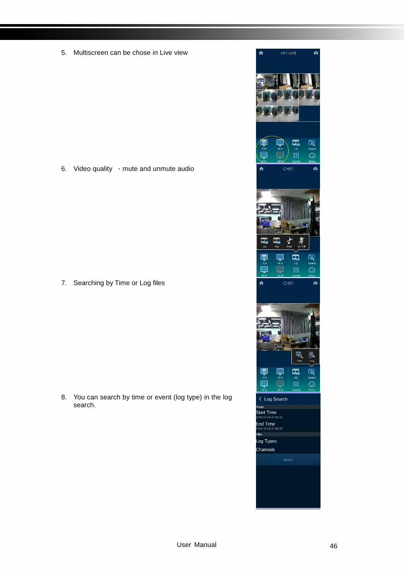
5. Multiscreen can be chose in Live view
6. Video quality 、mute and unmute audio
7. Searching by Time or Log files
8. You can search by time or event (log type) in the log
search.

User Manual 47
9. Highlights in the monthly calendar are those days which has video recording. Pick one of them and choose a start time to watch the recording.
10. Play Rewind、Forward、Pause and Start/Stop
11. Mute and unmute the audio
12. Switch multiscreen

User Manual 48
13. Choose a section of the recoding and back it down to your device
14. Other settings, such as PTZ、Relay、Zoom…etc.
15. Backup recording to your device

User Manual 49
11 P2P Connection Setup
How to Setup
1. On your DVR/IVR, please go to Network Setup page: Main control panel => Configuration => Network Setup
2. On lower part of Network Setup page, please input P2P Access Key for
P2P and press Apply button.
Please press OK button on lower part of Network Setup page and return to Configuration level.
3. lease go to System Information page:
Main control panel => Configuration => System Information Under Network tag, you can find QR code, access key and expiry date for P2P feature.

User Manual 50
4. For computer use, please login Swift Connection. On prompting interface, please input P2P Access Key in Host field, input / modify the rest of fields as appropriate Click on Connect button
5. For mobile device (i.e., smart phone and tablet) users, please login APP “Swift Connection.” Click ‘+’ (iOS) / (Android) icon on upper right corner to add a new connec-tion.
6. Click on Scan QR code button as shown on following picture.
iOS Android
Android iOS

User Manual 51
7. Please scan QR code on DVR’s System Information page
8. Access key information will be shown on Host field
Input / modify the rest of fields as appropriate. Click on Save button on upper right corner. Login with new settings

User Manual 52
Appendix : IVS setup DUHD IVS relevant setting instructions 1.DUHD relevant parameters setting in the advanced setup of the camera are stored in the camera, if change to different channel, it will not need to reset the parameter. 2. The DUHD camera relevant functions of the IVS event settings are stored in the DVR.
User Manual 53
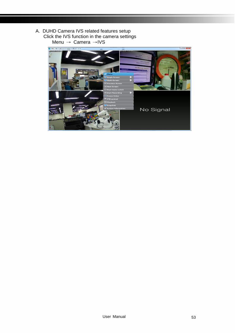
A. DUHD Camera IVS related features setup Click the IVS function in the camera settings
Menu → Camera →IVS

User Manual 54
1. The IVS mode contain (PEA) and the (People Counting) Note: Each DUHD camera supports only one mode at the same time
A. In the PEA mode, it support four cordon lines with a block area to detection

User Manual 55
In the part of the cordon, you can draw your own line / prohibited direction and whether you want to enable the detection of this cordon Note : The Arrow is for the prohibited direction, One way means one-way prohibition, Two Way means two-way prohibition
User Manual 56
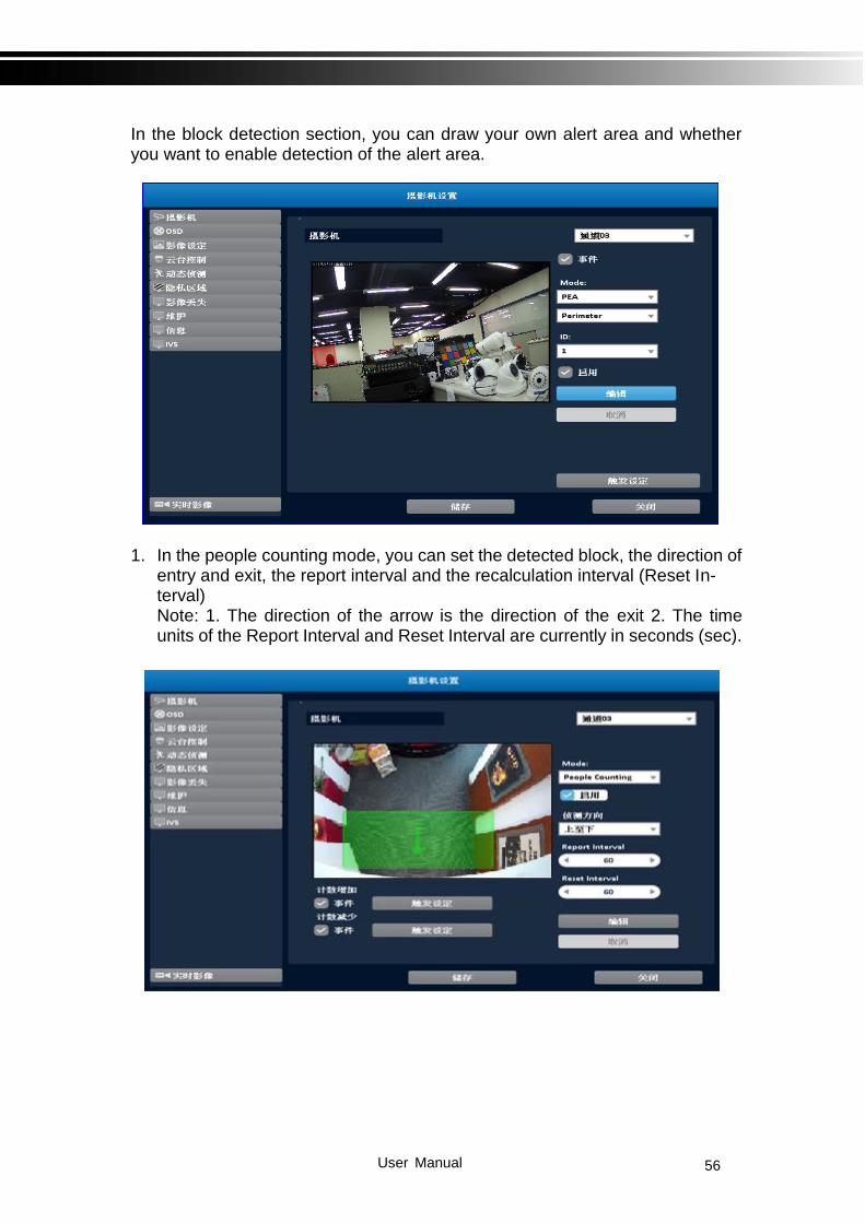
In the block detection section, you can draw your own alert area and whether you want to enable detection of the alert area.
1. In the people counting mode, you can set the detected block, the direction of
entry and exit, the report interval and the recalculation interval (Reset In-terval) Note: 1. The direction of the arrow is the direction of the exit 2. The time units of the Report Interval and Reset Interval are currently in seconds (sec).

User Manual 57
B. DUHD Camera IVS trigger pop-up settings
People Counting •Environmental requirements: light stability, adequate light, clear detail
•Camera set up, the lens is completely parallel to the ground, a slight offset is allowed to be able to shoot to the human of the head and shoulder shall prevail.
Adjust the camera so that the ground occupies approximately 2/3 to 3/4 of the width of the screen, leaving a certain space on both sides and making the flow channel in the middle of the screen. For example: white floor, dark hair, dark tops, full portrait size.

User Manual 58
1. The PEA-related functions are divided into continuous display (Line / Boundary Show) and the (Event Show), the part of People Counting is only supported for continuous display and no display.
1. Displayed in green in non-triggered state in PEA mode, red when the event is sent
2. In People Counting, the current total number and the nearest direction are displayed. Note: Counter table is currently counted in the total number of internal, dir that direction, in to the 1, out to -1. (Future in the evaluation of display)
User Manual 59
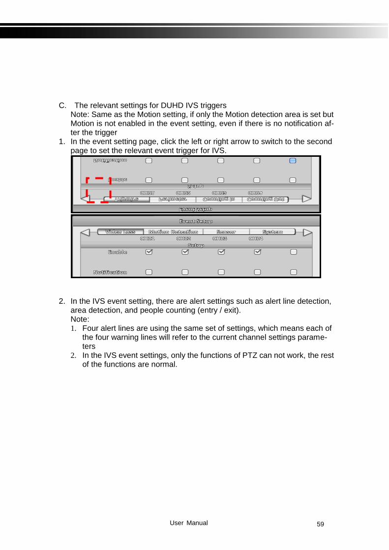
C. The relevant settings for DUHD IVS triggers
Note: Same as the Motion setting, if only the Motion detection area is set but Motion is not enabled in the event setting, even if there is no notification af-ter the trigger
1. In the event setting page, click the left or right arrow to switch to the second page to set the relevant event trigger for IVS.
2. In the IVS event setting, there are alert settings such as alert line detection, area detection, and people counting (entry / exit). Note: 1. Four alert lines are using the same set of settings, which means each of
the four warning lines will refer to the current channel settings parame-ters
2. In the IVS event settings, only the functions of PTZ can not work, the rest of the functions are normal.

User Manual 60
3. How does the system record presented? The system records have been added to Tripwire, Perimeter and People Counting.

User Manual 61