Embed Size (px)
Citation preview
1
➧ Cells discovery and exploration
Chapter
1Activity 1.1
Cells discovery and exploration
What’s in a shape?
Intended learning outcomes
INTRODUCTION
Microscopic examination of sections of tissues and organs is an important part ofbiology. Sections cut through different planes of an organism or its parts may result inquite different pictures. Through examination of these pictures, an idea of the internalstructure of the organism or its parts can be built up. In this activity you will cutsections through different planes of familiar objects to enable you to relate thedifferent sections you observe to the structure of the whole object.
MATERIALS
Select from the following:apples; oranges; bananas; pieces of celery; boiled eggs; tomatoes; Kiwi fruit; onions;pumpkin; pieces of licorice — solid and hollow sticks; licorice allsorts; other materialprovided by your teacher.
Cutting implement
Examining a familiar objectYou have probably eaten many different fruits and know their general internal struc-ture but it is unlikely that you have cut a piece of fruit into thin slices in the same waythat sections are cut out of biological tissue. Sections can be cut in different ways.When you cut a section it is important to indicate the plane in which the section hasbeen cut.
The cuts are described as vertical, horizontal or transverse, oblique and longitudinaldepending on the external appearance of the structure being sectioned as well as theplane of the cut. If a number of thin sections is cut from a structure, one after the other,the term serial sections is used.
Assume that you wish to take sections from a fruit. Some of the terms used todescribe sections are given in figure 1.1A. Each line represents a thin slice taken fromthe fruit through the position shown.
Figure 1.1A
This activity has been designed to enable you to:
• predict the appearance of a section(a slice of tissue) taken from a known structure
• interpret a given section and determine its position in the whole structure
• relate the sections you examine through a microscope in later activities to their position in the whole structure.
WARNINGTake care when using any cutting implement.
Transverse or horizontal section
Kiwi fruit
Vertical serial sections as seen from above
Transverse or horizontal serial sections
Longitudinalsection
Transverse section
Vertical serial sections
Apple
Oblique section
Vertical section
2
NATURE OF BIOLOGY BOOK 1 THIRD EDITION ACTIVITY MANUAL ➧
Each group will work with different material. The number of sections you cut willdepend on the kind of material you have.
1. Think about the material you have for sectioning. Decide through which plane
you will first cut serial sections (e.g. vertical or horizontal). Discuss with your
partner what you think the sections will look like. Will they all look the same?
In what way might they differ?
2. Cut the serial sections through the chosen plane of your fruit, vegetable or
other material.
3. Draw your fruit or other material and mark and label the position and type of
sections you cut. Draw examples of the sections you obtained.
4. Prepare your material for examination by other members of the class. Draw your
object in the corner of a piece of paper and mark and label the positions and
type of sections you cut. Line up the sections, in order, on a piece of paper.
5. Start again with a whole piece of the same material and repeat the procedure
1 to 4 for serial sections through a different plane.
6. Examine the sections cut by other members of your class.
7. Draw the longitudinal and transverse sections from a structure in which those
sections look different. Indicate the planes and positions from which the
sections have been cut on a drawing of the structure.
8. Vertical, transverse and oblique sections through an orange differ from each
other. Draw an orange. Mark the positions of the three types of section and
draw each section.
Q1. Were your predictions about the likely appearance of your sections
confirmed by your observations? If not, in what way did your prediction
differ from your observation?
Q2. Were the serial sections of any structure you examined in class exactly the
same whatever the plane of the cut? If so, which ones?
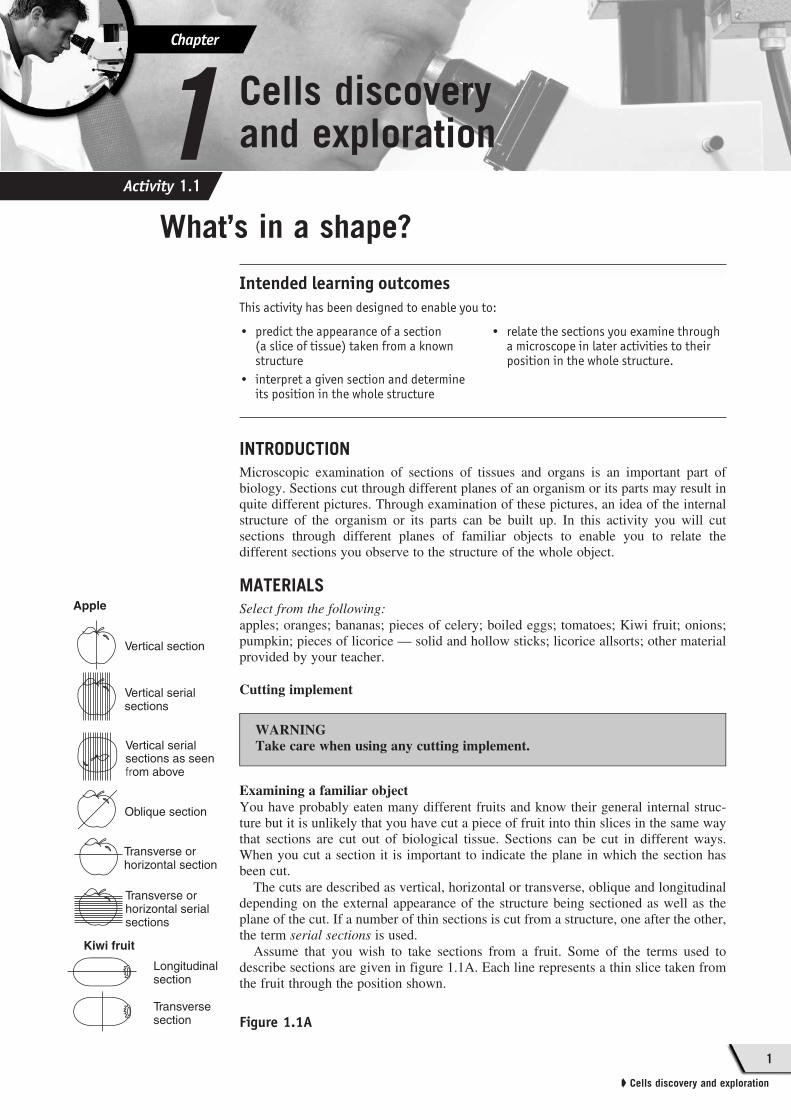
Q3. A single-celled organism, roughly spherical in shape with some cell
extensions, was embedded in wax. Four thin sections were cut (AA', BB',
CC', and DD', see figure 1.1C) and examined with a microscope. Based on
the information you have about the organism, draw the four sections as you
would expect to see them.
Q4. Five vertical, serial sections taken through an object appeared as shown in
figure 1.1B.
Predict the shape of the object. Draw a transverse section from the object.
Q5. Five vertical, serial sections taken through an object appeared as shown in
figure 1.1D.
Predict the shape of the object. Draw a transverse section from the object.
Q6. When cutting sections through the material used in the practical, what
precautions did you take to make sure you did not cut yourself?
Your task(groups of 2)
Figure 1.1B
Figure 1.1DFigure 1.1C
1 2 3 4 5
AB
C
D
C'
D'
A'
B'
Activity 1.1

Activity 1.2C
ha
pte
r 1
3
➧ Cells discovery and exploration
Exploring one of the tools of the biologist — the microscope
Intended learning outcomes
INTRODUCTION
The microscope enables a biologist to see the organisation and structure of very smallthings. How does a microscope do this? You probably are already aware that a micro-scope magnifies, but there is a second function which may be less obvious to you. Themicroscope resolves.
Magnifying means enlarging an object. What is meant by resolution? Resolutionmeans seeing the detail of a structure. As well as enlarging the object, you need to beable to distinguish the individual parts. Figure 1.2Aa shows the effect of increasedmagnification; figure 1.2Ab shows increased magnification and increased resolution.What difference does the improved resolution make?
In this exercise you will see how you can use your microscope to magnify andresolve.
The microscopes you are most likely to have in your laboratory are monocular com-pound microscopes; they may have a moveable or fixed stage and an internal orexternal light source. You may have stereo microscopes, too. What do all these termsmean? Let’s take a closer look.
MATERIALS
For part A: monocular microscope; lamp; lens paper.For part B: slides; coverslip; mounted needle; tissue paper; pen; scissors; Pasteurpipette; forceps; plastic ruler or minigrid.
PART A: Identifying the parts of the microscope1. The light microscope
Place the microscope on the bench in front of you. The description light
microscope is used for this type of microscope.
Q1. What is the simplest form of magnification you can think of?
Q2. Have you heard of any other types of microscope? If so, what are they?
The light microscope relies
on the bending (refraction) of
light rays by lenses, so that the
rays converge onto the object
you are observing (figure 1.2B).
The combination of several
lenses makes it a compound
microscope.
It is important that whatever
specimen you are studying
allows light to pass through it.
Two microscopes are shown
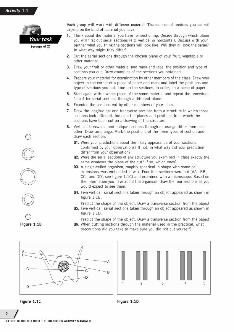
in figure 1.2C (p. 4). They may
not be identical to the one you
have, but the main parts will
serve a similar function.
This activity has been designed to enable you to:
• recognise the parts of a monocular compound microscope
• operate a monocular microscope
• use the microscope to measure the size of a small object.
Figure 1.2A The effects
of increased magnification
and resolution
(a) Increased magnification
(b) Increased magnification and resolution
Your task
Focal
length
•Focal
point
Image
planeLens
� �
� �
Figure 1.2B Focusing of light rays
Activity 1.1
4
NATURE OF BIOLOGY BOOK 1 THIRD EDITION ACTIVITY MANUAL ➧
2. The stage
Identify the stage of your microscope. This is where you will place the slide.
Q3. Is the stage of your microscope moveable or fixed?
If the stage is moveable, it will be operated by two knobs. Identify these and
familiarise yourself with the movement of the stage.
If the stage is fixed, you will have to place the slide under two clips. When
you want to move the slide, you will have to move it manually.
Look at the parts of the microscope above the stage. Identify (a) the
microscope tube or barrel, (b) the eyepiece, and (c) the objective lenses.
3. The eyepiece
Note: It is important that you do
not touch the lenses or allow dust
to enter the lens system. Therefore,
always handle the eyepieces and
objectives with care, and clean
them only with lens paper.
Remove the eyepiece and look
down the barrel. You will notice it
is hollow and will transmit light up
through the object to your eye.
(Later you will look at ways of
controlling the light that is
transmitted up the barrel.)
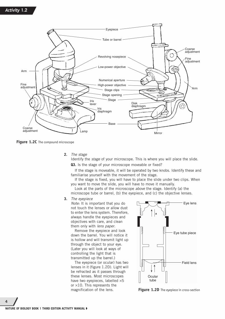
The eyepiece (or ocular) has two
lenses in it (figure 1.2D). Light will
be refracted as it passes through
these lenses. Most microscopes
have two eyepieces, labelled ×5
or ×10. This represents the
magnification of the lens.
Figure 1.2C The compound microscope
Eyepiece
Tube or barrel
Revolving nosepiece
Low-power objective
Numerical aperture
High-power objective
Stage clips
Stage opening
Stage
Base
Arm
Arm
Fineadjustment
Fineadjustment
Coarseadjustment
Coarseadjustment
Mirror
Diskdiaphragm
Iris diaphragm
Iris lever
Lamp
Eye lens
Eye tube piece
Field lens
Ocular
tube
�
�
�
�
Figure 1.2D The eyepiece in cross-section
Activity 1.2
5
➧ Cells discovery and exploration
4. The objective lens
The objective lenses are screwed into a revolving nosepiece. There will be at
least two and possibly three objectives on your microscope.
To move the objectives up and down, there are two knobs. The larger knob,
called the coarse adjustment knob, moves the barrel of the microscope a large
distance per rotation. The smaller knob, called the fine adjustment knob,
moves the barrel a small distance for each rotation.
Take a closer look at the objectives. You will notice numbers engraved on
each lens. One of these refers to the magnification of this lens and will be, in
most cases, ×10 or ×40. You may have another lens which magnifies ×4.
Q4. Which lens is the longer — ×10 (low power) or ×40 (high power)?
If you have a lens marked ×4 (referred to as a scanning lens), where does it
fit in terms of length?
There may be a space on the revolving nosepiece. This is reserved for another
lens, called an oil immersion lens, which magnifies 100 times. For its effective
operation, oil is used.
With the low-power objective in position, practise moving the objective lens
up and down.
Note: It is most important that when the high-power objective is in position,
you use only the fine adjustment to focus.
You will notice another measurement engraved on the objective lenses. This
is the numerical aperture and relates to the resolving power of the lens.
5. The light source
In the case of a built-in light source, a lamp will be fixed to the microscope
base. This will be operated by a switch.
In the case of an external light source, a lamp or natural light from a window
can be used. It is necessary to focus this light so that it is transmitted through
the specimen to the eyepiece by adjusting a mirror. If there are two sides to
your mirror, a plane side and a concave side, you should use the plane side if
your external light source is a lamp and the concave side if the light source is
the sun. The concave side of the mirror redirects the parallel light rays from the
sun onto the specimen.
To check that the mirror is in the right position, place the low-power
eyepiece and ×10 objective in position and look down the barrel. Light should
fill the opening.
Q5. Why is it important that the object on the slide is transparent?
6. The iris diaphragm
Refer to figure 1.2C (p. 4) and locate the iris diaphragm and its controlling
lever on your microscope. Remove the eyepiece and, while looking down the
barrel, open and close the iris diaphragm.
Q6. What do you notice?
This adjustment controls the diameter of the circle of light entering each
objective and influences the resolution of the microscope.
7. The condenser
Refer to figure 1.2C (p. 4) and locate the condenser on your microscope. In
association with the iris diaphragm, the condenser is used to improve
resolution. The important role of the condenser is to focus light onto the
opening of the objective lens. There is a lens in the condenser to help achieve
this. The aperture of the iris diaphragm is also important to this function.
The best resolution of your microscope will be obtained when the amount of
light which enters through the iris diaphragm is focused by the condenser in
such a way that it just fills the front lens of the objective (figure 1.2E).
The condenser may be fixed, or may be moved by using the condenser knob.
Usually the best resolution is obtained if the condenser is about 2 mm from the
stage.
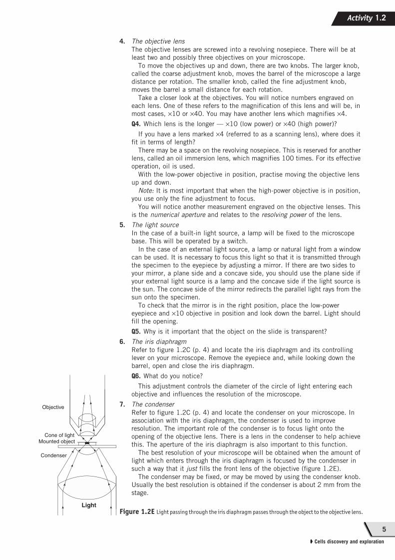
Figure 1.2E Light passing through the iris diaphragm passes through the object to the objective lens.Light
➤➤
➤ ➤
➤➤
➤
➤➤
➤➤
➤➤
➤➤
Condenser
Mounted objectCone of light
Objective
Activity 1.2
6
NATURE OF BIOLOGY BOOK 1 THIRD EDITION ACTIVITY MANUAL ➧
If the condenser has a control knob, you can check that it is in the correct
position for the objective you are using by doing the following:
a. remove the eyepiece
b. place the low-power objective in position
c. place a pencil on the mirror (if an external light source is used) or on the
fixed light source
d. move the condenser until you see a sharp image of the pencil.
PART B: Using the microscope1. Adjust the mirror to capture light from a window or a lamp so that light shines
up the barrel of the microscope. (Switch on the light if the light is internal.)
2. If the condenser is moveable, adjust it as described in step 7 of part A
(see above).
3. To adjust the iris diaphragm, remove the eyepiece and move the control lever of
the iris diaphragm so that the edge of the diaphragm can just be seen at the
perimeter of the field of view.
4. Use a ballpoint pen to draw a tiny letter ‘e’ near the edge of a piece of tissue
paper. Cut out this letter with scissors and, using forceps, place the piece
of tissue in the centre of a slide. With a Pasteur pipette, add a drop of water.
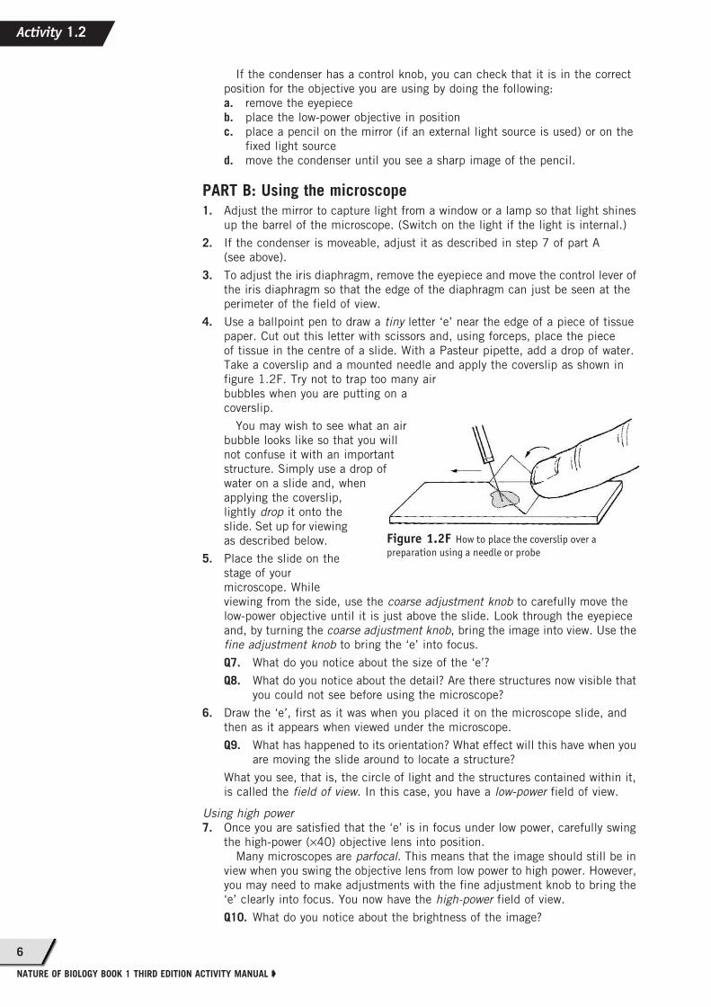
Take a coverslip and a mounted needle and apply the coverslip as shown in
figure 1.2F. Try not to trap too many air
bubbles when you are putting on a
coverslip.
You may wish to see what an air
bubble looks like so that you will
not confuse it with an important
structure. Simply use a drop of
water on a slide and, when
applying the coverslip,
lightly drop it onto the
slide. Set up for viewing
as described below.
5. Place the slide on the
stage of your
microscope. While
viewing from the side, use the coarse adjustment knob to carefully move the
low-power objective until it is just above the slide. Look through the eyepiece
and, by turning the coarse adjustment knob, bring the image into view. Use the
fine adjustment knob to bring the ‘e’ into focus.
Q7. What do you notice about the size of the ‘e’?
Q8. What do you notice about the detail? Are there structures now visible that
you could not see before using the microscope?
6. Draw the ‘e’, first as it was when you placed it on the microscope slide, and
then as it appears when viewed under the microscope.
Q9. What has happened to its orientation? What effect will this have when you
are moving the slide around to locate a structure?
What you see, that is, the circle of light and the structures contained within it,
is called the field of view. In this case, you have a low-power field of view.
Using high power
7. Once you are satisfied that the ‘e’ is in focus under low power, carefully swing
the high-power (×40) objective lens into position.
Many microscopes are parfocal. This means that the image should still be in
view when you swing the objective lens from low power to high power. However,
you may need to make adjustments with the fine adjustment knob to bring the
‘e’ clearly into focus. You now have the high-power field of view.
Q10. What do you notice about the brightness of the image?
Figure 1.2F How to place the coverslip over a
preparation using a needle or probe
Activity 1.2

7
➧ Cells discovery and exploration
8. Open and close the iris diaphragm to see its effect on the resolution of the
detail in your ‘e’. Choose the aperture that gives you the best resolution.
Measurement with the microscope
It is important that in order to communicate with fellow scientists you can describe
the size of a structure. To establish the size of an object under the microscope, you
need to complete three tasks:
Task 1. Measure the diameter of the field of view.
Task 2. Estimate the number of structures that will fit across the diameter of this
field.
Task 3. Complete a simple calculation.
9. To measure the diameter of the field of view, you will need a transparent
plastic ruler or a minigrid. Use the ×10 eyepiece and the ×10 objective. Place
the ruler or minigrid on the stage, and focus on the markings.
You will notice in the hypothetical example in figure 1.2G that the diameter
is more than 1 mm. To estimate the fraction of a millimetre left over, move the
markings to the edge of the field of view and estimate the fraction. In this case
the diameter is about 1.5 mm.
Convert this measurement to micrometres (μm). This allows you to give the
size of a very small structure in an appropriate unit. (1mm = 1000 μm)
10. Use this method to measure the diameter of the low-power and
high-power fields of your microscope.
It is important to identify the microscope you have used. The
measurements will vary from one model to another and even between
microscopes of the same model. If possible, use the same microscope all year
so that you don’t have to perform the measurements more than once.
You could perform similar measurements for the ×5 eyepiece.
11. The second step in calculating the size of a structure is to estimate
the number of specimens or structures that will fit across the low- or
high-power field.
Figure 1.2Ha shows what you may see under the microscope. Figure 1.2Hb
shows what you have to visualise to be able to estimate the number of
structures that will fit across the diameter of the field of view. In this
example, approximately 11 ‘roundies’ fit across the diameter of this field of
view.
12. The third step is a simple calculation. If the diameter of this field of view is
1500 μm and 11 ‘roundies’ fit across the diameter, then the size of each
‘roundie’ is:
Therefore a ‘roundie’ measures approximately 136 μm.
Q11. Given that 1 mm is equal to 1000 μm, approximately how many
‘roundies’ would fit across a 1 mm interval on a ruler?
Q12. To work out the scale, calculate the size of the structure under the
microscope using the method outlined above. Say, for example, a
structure measures 50 μm. Now measure your drawing of the structure.
Suppose your drawing is 10 cm across. Your scale is 1 cm = 5 μm. This
means that 1 cm on your drawing is equivalent to 5 μm under the
microscope. You can show this in diagrammatic form near the drawing
by ruling a line 1 cm long. Under this line insert its equivalent value as
seen under the microscope.
Q13. It is important to care for your microscope. What steps did you take
during this activity to make sure that the lenses in particular were not
damaged?
Figure 1.2G
Move ruler marking to edge of field to estimate fraction.
➤
(a)
(b)
Figure 1.2H(a) What you may see under
the microscope
(b)What you have to visualise
sizediameter of field of view
number of objects across diameter------------------------------------------------------------------------------------------=
1500
11--------------=
Activity 1.2
8
NATURE OF BIOLOGY BOOK 1 THIRD EDITION ACTIVITY MANUAL ➧
Activity 1.3C
ha
pte
r 1
Viewing andstaining cells
Intended learning outcomes
INTRODUCTION
In both unicellular and multicellular eukaryotic organisms most functions essential tolife occur within the organelles of individual cells. Using a light microscope it is poss-ible to see some cell organelles because of the differences in density or light trans-mitted between the organelle and the surrounding medium. Some objects are difficultto visualise under the light microscope because of a lack of contrast between the objectand the surroundings. To increase this contrast, staining is often used. Staining maykill a cell or change it in some way.
MATERIALS
Compound microscope; slides; coverslips; razor blade; toothpick; normal saline;water; pipette; methylene blue; aceto-carmine; aceto-orcein; iodine, disposable gloves.For part A: onion; banana (firm, greenish); tomato; rhubarb; Anacharis leaf;Tradescantia flower.For part B: Chlamydomonas culture; Amoeba culture; Paramecium culture.
PART A: The use of stain
It is very difficult to identify structures in many preparations. For example, cells arealmost transparent, and there is poor contrast between the structures within the cell andbetween the cell and the background. Chemical stains can be used to provide greatercontrast between the structures of the cell and the background, or to highlight a par-ticular structure within the cell. Stains may be toxic and may also discolour yourclothes permanently. Wear gloves to protect your skin and a laboratory coat to protectyour clothes.
Observing living tissue — onion epidermis
1. Peel off the dry outer skin of an onion. Using forceps, peel off a small section
of the transparent outermost layer, the epidermis. Place the onion tissue in a
drop of water on a slide. Apply a coverslip.
2. Focus under low power and locate one or two cells from the epidermis. When
you have the cells in the centre of the field of view, swing the high-power
objective into position and adjust the focus and iris diaphragm.
Q1. Are you able to distinguish between structures within the cell?
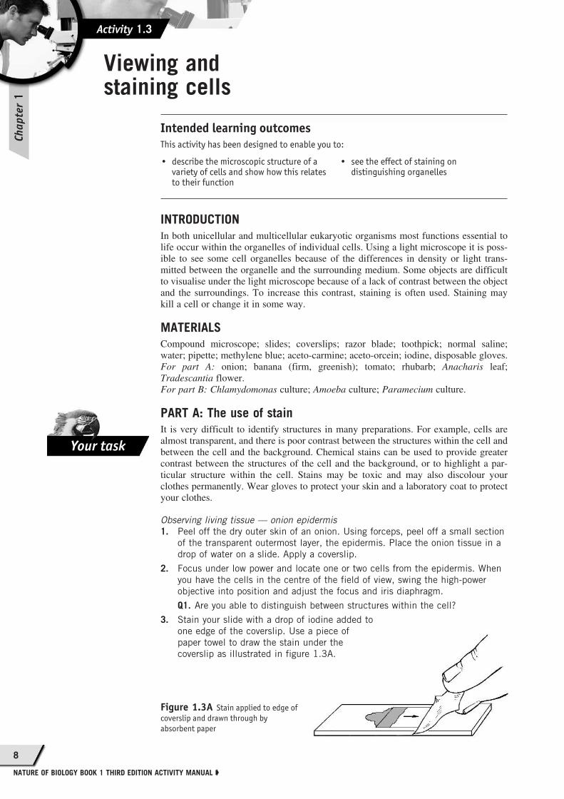
3. Stain your slide with a drop of iodine added to
one edge of the coverslip. Use a piece of
paper towel to draw the stain under the
coverslip as illustrated in figure 1.3A.
Figure 1.3A Stain applied to edge of
coverslip and drawn through by
absorbent paper
This activity has been designed to enable you to:
• describe the microscopic structure of a variety of cells and show how this relates to their function
• see the effect of staining on distinguishing organelles
Your task

9
➧ Cells discovery and exploration
Q2. What effect did the use of stain have on the detail you could resolve in the
cells? Did the stain improve the contrast of the:
a. nucleus?
b. cytoplasm?
c. granules in the cytoplasm?
4. If there is insufficient stain on the slide or the slide begins to dry out, add more
stain by placing a drop on the slide at the edge of the coverslip. Using an
absorbent piece of paper, tissue or paper towelling, draw the stain through the
preparation.
5. Using the stained preparation, determine the size of a cell (in micrometres)
using the high-power field of view (see activity 1.2). Compare the
measurements you obtain with those of other members of the class.
PART B: Microscopic drawing
Using a sheet of plain white paper and a sharp HB pencil, draw one onion
epithelial cell as you see it under high power, following the conventions set out
below:
• You draw what you see.
• Your outline of a structure is a single firm line.
• A straight line is used to link a structure and its label.
• Labels are printed and horizontal.
• Indicate the total magnification used (e.g. ×400 if you have the ×10 ocular and
×40 objective in position).
A scale may also be added to indicate the relative size of the structures.
PART C: Observing living tissue
1. Work with a partner, and share the preparation of the slides. This should help
you to examine a large number of cells in a relatively short time.
2. Draw up a data sheet in your logbook similar to that shown below (table 1.3A).
Table 1.3A
Name of organism
Plant (P) orAnimal (A) orProtista (PT)
Size of cell (μm)
Magnification
Nucleus
Cytoplasm
Cell wall
Cell membrane
Nucleolus
Vacuole
Green plastid (Chloroplast)
White plastid (Leucoplast)
Coloured plastid (Chromoplast)
Cytoplasmic movement
Activity 1.3
10
NATURE OF BIOLOGY BOOK 1 THIRD EDITION ACTIVITY MANUAL ➧
Record your observations of each cell in the data chart. Insert a tick (✓) if the
structure is clearly visible, a question mark (?) if you are not sure, and a dash
(—) if the structure is clearly NOT visible. Be sure to work out the size of each
cell and to record the magnification.
3. For each cell type you examine, make a large (one-third or half page size)
diagram. Use a sharp pencil to draw and label your cell. You should state
the magnification used (e.g. H.P. 10 × 40 = 400), and the dimensions of
the cell in micrometres (μm). Clearly and neatly label all structures that are
visible.
Investigating plant cells
You are not expected to complete all cell types. Your teacher will tell you which of thefollowing preparations to make during the class.
Onion epidermis
1. Use the preparation of onion epidermis from part A to complete table 1.3A.
Banana cells
Peel the banana, and scrape a very small amount of tissue from the fruit and smear
it onto a clean glass slide. You must use very little, otherwise you cannot see
individual cells clearly. Add a drop of water and a coverslip. Try staining with iodine
as you did for the onion cells.
Q3. Can you see any structures in banana cells that were not present in the
onion? Suggest what they might be.
Tomato cells
Peel a little skin off a ripe tomato. Scrape a small amount of tomato pulp and
smear onto a clean glass slide. Add a drop of water and a coverslip and examine.
Q4. What are the coloured structures visible in the unstained slide? What
happens when you stain the cell with iodine?
Rhubarb epidermis
1. On a clean slide place a drop of distilled water.
2. Obtain a small section of the rhubarb petiole and with forceps peel back a
small section of the red-coloured outer epidermal layer.
3. Place the piece of epidermis in the water on the slide. Cover with a coverslip
and view under low power of the microscope.
Q5. What is the most obvious structure in the cell?
Q6. How can you identify the position of the vacuole membrane?
Q7. Apply a drop of aceto-orcein to the slide. Does it highlight any other
structures in the cell?
Anacharis leaf
Select a small leaf from the growing tip of the Anacharis shoot, and place it in a
drop of lukewarm water on a warmed glass slide. Add a coverslip. Focus under low
power, then examine an individual cell under high power. These cells are in layers,
so be sure you focus carefully on one cell.
Q8. What are the most obvious structures within the cells? Are they similar to
the structures in the other plant cells you have examined?
Q9. Have you any evidence that these cells are alive? Explain.
Q10. What differences, if any, do you see in the stained cell?
Tradescantia flower
Select 2 or 3 fine hairs from around the base of the stamens of the Tradescantia
flower, and place them in a drop of warm water on a warmed slide. Add a coverslip
and examine carefully under low power. Once you have found an entire cell, you
may use high power to see more detail.
Q11. Have you any evidence that these cells are alive? What happens when you
stain these cells with iodine? Can you explain this?
Activity 1.3
11
➧ Cells discovery and exploration
Activity 1.4
Ch
ap
ter
1
Investigating protists
Chlamydomonas culture
Use a pipette to take a drop of the culture and place it on a glass slide. Add a
coverslip, and examine. Try staining the preparation with aceto-carmine stain.
Q12. How do these cells differ from the cells examined previously?
Amoeba culture
1. Take a drop from the bottom of the Amoeba culture and place it carefully on a
slide. Add a coverslip, and examine under low power. Take a little time and
search the whole slide for Amoeba.
2. Because the Amoeba may be disturbed by your rough treatment, the cell may
be rounded up and immobile. You must wait until the organism moves away
before you can really observe it well. When you have completed your
observations, stain with aceto-carmine.
Q13. How does the Amoeba differ from the plant cells previously examined?
Q14. What changes did you observe as a result of staining the cell?
Paramecium culture
1. Take a drop from the Paramecium culture, and place it on a slide. Add a coverslip
and examine under low power. If the cells move too quickly for you to follow,
try teasing out a little lens tissue, place it in the middle of the slide and then
add a drop of the culture. The strands of the tissue act as a ‘fence’ to slow down
the Paramecia.
2. Identify all the structures you can see — you might like to check a reference.
Finally, stain with aceto-carmine.
Q15. What additional structures are visible after the stain was added?
Q16. Compare your data sheet with that of another group. Are the data identical?
Explain any differences.
Q17. Were there any structures found in all the cells you examined?
Q18. How can you distinguish between a plant cell and an animal cell?
Q19. What precautions do you need to take when using stains?
What limitsthe size of cells?
Intended learning outcomes
INTRODUCTION
Human red blood cells have a diameter of about 7 μm. More than 100 red blood cellscould be lined up across a distance of one millimetre. Even the largest human cell, anegg cell, is only about 200 μm in diameter. To examine cells, the human eye must be
• develop an understanding of the concepts of surface area and volume
• recognise how the surface area to volume ratio (SA:V) of cells and objects of various shapes can differ
• comprehend how the relationship between the area and the volume of a cell affects the efficiency of supply of substances to and removal of wastes from it
• apply SA:V ratio considerations to biological situations.
Activity 1.3
12
NATURE OF BIOLOGY BOOK 1 THIRD EDITION ACTIVITY MANUAL ➧
aided by one of various kinds of microscope. Other kinds of organism also containmicroscopic cells. Plant cells vary from 10 to 100 μm in diameter. Bacterial cells arecomparatively smaller. For example, the pneumonia-causing bacterium, Diplococcuspneumoniae, comprises a single cell just 0.1 μm in diameter.
Why are cells so small? Is cell size limited in some way? Why aren’t some cells thesize of bricks? Reaching answers to these questions can be helped in part by consid-ering the concept of surface area to volume ratio (SA:V).
The surface area of an object is a measure of its exposed outer surface. We are veryaware of this concept if we have to paint or polish a surface — the larger the surface,the longer time the task will take. Area is commonly expressed in units such as squarecentimetres (cm2) or square metres (m2).
The volume of an object refers to the space taken up by the object. The basic unit ofmeasurement of volume is the litre (L). Volume of liquid matter is commonlyexpressed in units such as litres (L) or millilitres (mL). For example, the blood of anaverage adult female occupies a volume of about 4.5 to 5.5 L, while that of an averageadult male occupies a volume in the range of 5 to 6 L. The volume of solid matter,such as the human brain, is sometimes expressed in cubic centimetres (cm3). Youshould note that 1 cm3 is equivalent to 1 mL.
The relationship between the surface area of an object and the space taken up by theobject is a number known as the surface area to volume (SA:V) ratio. This ratio isobtained by dividing the surface area by the volume. So, a cube with a surface area of24 cm2 and a volume of 8 cm3 has a SA:V ratio of 3, that is 24/8. A ratio is simply anumber and it has no units. Knowing the SA:V ratio allows you to identify how manyunits of surface area are available for each unit of volume. In the case of a cell, thehigher the SA:V ratio, the more units of surface are available to take up material tosupply its internal contents or to allow wastes to be expelled.
Note:In the International System (SI system), the unit of volume is based on metric volumessuch as the cubic centimetre (cm3) and the cubic decimetre (dm3). The litre (L) isanother unit of volume that is accepted and in use, but is not an SI unit. The relation-ship between these units is: 1 L = 1.000 002 5 dm3, and so 1 millilitre (mL) is approxi-mately equal to 1 cm3. In this activity, you will use millilitres (mL) since this will be aunit with which you are probably familiar.
The abbreviation for litre is most commonly a lower case ‘l’; however, a capital ‘L’is acceptable. To avoid confusion with the numeral ‘1’, this manual uses capital ‘L’.
MATERIALS AND RESOURCES
2 larger-diameter pink agar cylinders in a petri dish, labelled A; 2 smaller-diameterpink agar cylinders in a petri dish, labelled B; plastic ruler; ‘food solution’; protectivegloves; wide-mouthed beaker; single-edged razor blade; calculator; Plasticine;balance.
Work in groups as directed by your teacher. You will be supplied with two petri dishes(A and B). Dish A contains two larger-diameter cylinders of a jelly-like substance,known as agar. Dish B contains two agar cylinders of smaller diameter. The agarcylinders should be kept moistened to prevent them from drying out.
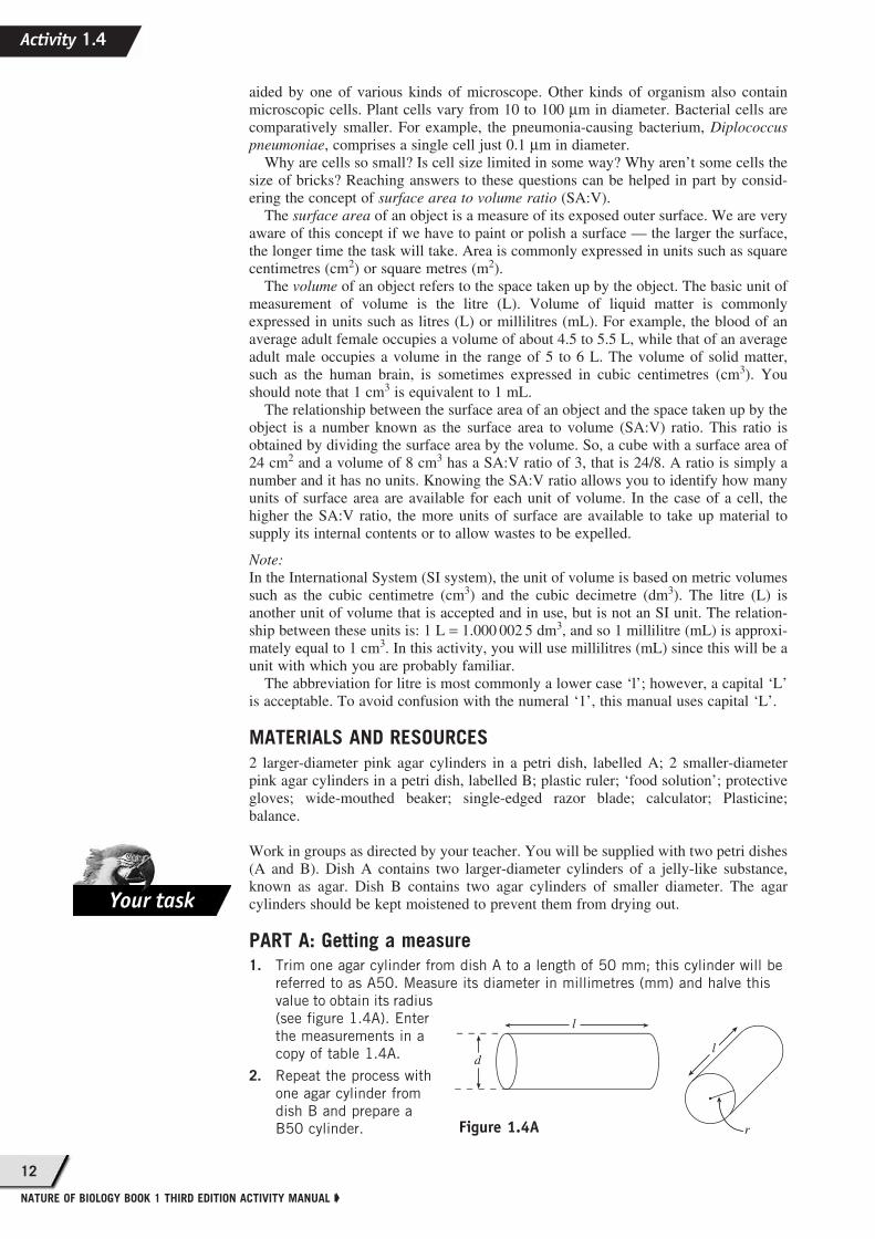
PART A: Getting a measure1. Trim one agar cylinder from dish A to a length of 50 mm; this cylinder will be
referred to as A50. Measure its diameter in millimetres (mm) and halve this
value to obtain its radius
(see figure 1.4A). Enter
the measurements in a
copy of table 1.4A.
2. Repeat the process with
one agar cylinder from
dish B and prepare a
B50 cylinder.
Your task
d
l
r
l
Figure 1.4A
Activity 1.4
13
➧ Cells discovery and exploration
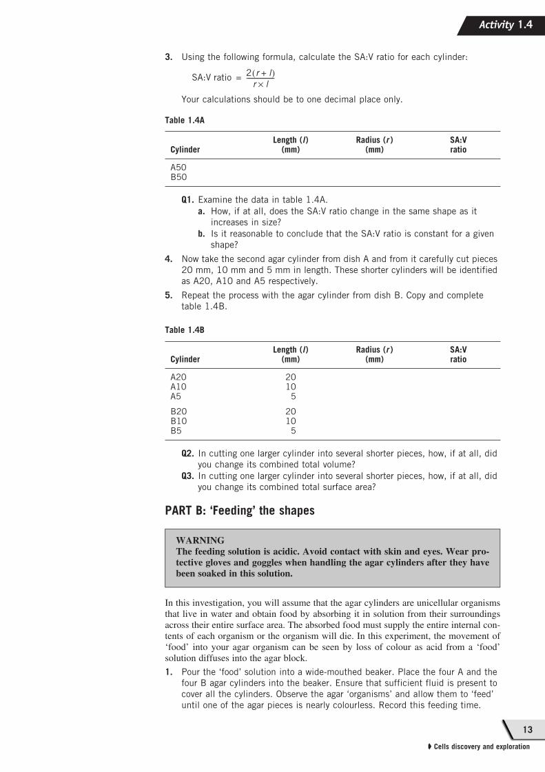
3. Using the following formula, calculate the SA:V ratio for each cylinder:
Your calculations should be to one decimal place only.
Q1. Examine the data in table 1.4A.
a. How, if at all, does the SA:V ratio change in the same shape as it
increases in size?
b. Is it reasonable to conclude that the SA:V ratio is constant for a given
shape?
4. Now take the second agar cylinder from dish A and from it carefully cut pieces
20 mm, 10 mm and 5 mm in length. These shorter cylinders will be identified
as A20, A10 and A5 respectively.
5. Repeat the process with the agar cylinder from dish B. Copy and complete
table 1.4B.
Q2. In cutting one larger cylinder into several shorter pieces, how, if at all, did
you change its combined total volume?
Q3. In cutting one larger cylinder into several shorter pieces, how, if at all, did
you change its combined total surface area?
PART B: ‘Feeding’ the shapes
In this investigation, you will assume that the agar cylinders are unicellular organismsthat live in water and obtain food by absorbing it in solution from their surroundingsacross their entire surface area. The absorbed food must supply the entire internal con-tents of each organism or the organism will die. In this experiment, the movement of‘food’ into your agar organism can be seen by loss of colour as acid from a ‘food’solution diffuses into the agar block.
1. Pour the ‘food’ solution into a wide-mouthed beaker. Place the four A and the
four B agar cylinders into the beaker. Ensure that sufficient fluid is present to
cover all the cylinders. Observe the agar ‘organisms’ and allow them to ‘feed’
until one of the agar pieces is nearly colourless. Record this feeding time.
Table 1.4A
CylinderLength (l)
(mm)Radius (r )
(mm)SA:Vratio
A50B50
Table 1.4B
CylinderLength (l)
(mm)Radius (r )
(mm)SA:Vratio
A20A10A5
B20B10B5
2010
5
2010
5
SA:V ratio2 r l+( )
r l×
------------------=
WARNINGThe feeding solution is acidic. Avoid contact with skin and eyes. Wear pro-tective gloves and goggles when handling the agar cylinders after they havebeen soaked in this solution.
Activity 1.4
14
NATURE OF BIOLOGY BOOK 1 THIRD EDITION ACTIVITY MANUAL ➧
2. Pour off the fluid and return it to its original beaker. Cut the agar pieces into
half along their long axes and observe how much colour remains in the various
agar pieces. Any coloured part represents regions of the cells that have not
obtained food.
For the mathematically minded only
3. Measure the coloured or ‘unfed’ regions to the nearest millimetre after feeding
and enter your data in a copy of table 1.4C. Data should be transferred from
tables 1.4A and 1.4B. Calculate the original volume (v0 ) and the volume of the
‘unfed’ region (v1) using the following formula:
volume = π r 2l where π =
4. Calculate the percentage of each organism that received nutrients by the end of
this feeding period using the following formula:
Percentage fed =
Q4. Which of the various cylinders has the largest region (by percentage) of
residual colour representing the area that has not received nutrients?
Q5. If the agar cylinders were organisms that fed in the manner described,
which organism is most efficient at feeding by diffusion? Which is at
greatest risk of dying because of lack of nutrients?
Q6. a. Compared with another organism of similar shape but very much
smaller size, what problems would be expected to exist in a unicellular
organism that obtains food by diffusion of dissolved organic material
across its surface?
b. Suggest why cells are typically microscopic in size.
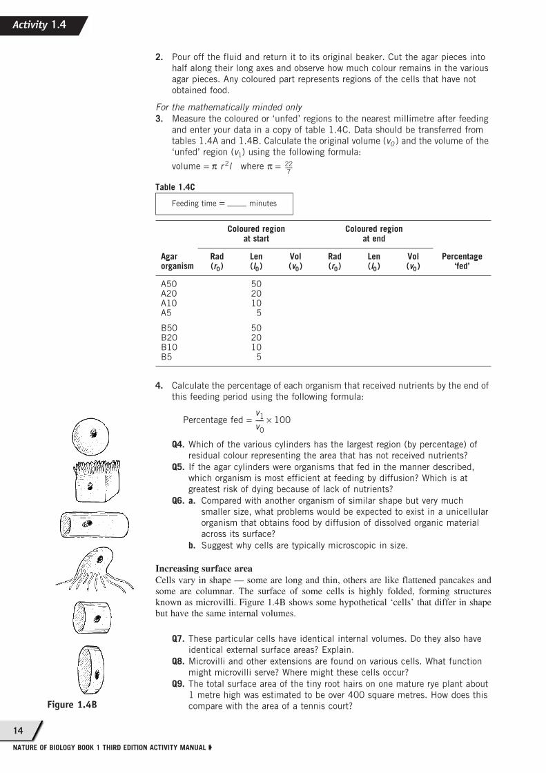
Increasing surface areaCells vary in shape — some are long and thin, others are like flattened pancakes andsome are columnar. The surface of some cells is highly folded, forming structuresknown as microvilli. Figure 1.4B shows some hypothetical ‘cells’ that differ in shapebut have the same internal volumes.
Q7. These particular cells have identical internal volumes. Do they also have
identical external surface areas? Explain.
Q8. Microvilli and other extensions are found on various cells. What function
might microvilli serve? Where might these cells occur?
Q9. The total surface area of the tiny root hairs on one mature rye plant about
1 metre high was estimated to be over 400 square metres. How does this
compare with the area of a tennis court?
Table 1.4C
Agarorganism
Coloured regionat start
Coloured regionat end
Percentage‘fed’
Rad(r0)
Len(l0)
Vol(v0)
Rad(r0)
Len(l0)
Vol(v0)
A50A20A10A5
B50B20B10B5
502010
5
502010
5
22
7-------
Feeding time = minutes
v1
v0
----- 100×
Figure 1.4B
Activity 1.4
15
➧ Cells discovery and exploration
Reducing surface areaSleeping cats and dogs curl into a tight ball on a cold day. In hot weather, the sameanimals typically can be seen sleeping stretched out. Some small hibernating mammalssnuggle tightly together in underground nests.
Q10. Is the exposed surface area of the animal affected by these positions?
Q11. Which position — ball or stretched out — produces the greater exposed
surface area?
Q12. Is the volume of the animal affected by these arrangements?
Q13. Which shape has the smaller SA:V ratio?
This behaviour is not related to the uptake of food into the animal or the removal ofwastes from it. Suggest a testable hypothesis that might provide an explanation forthese observations.
Q14. In light of this hypothesis, what prediction would you make about
perching birds in warm weather compared with cold weather?
Applications and issues
Same volume, different shapesDivide a lump of Plasticine into 5 equal portions. Use a balance to ensure that theportions are equal in mass. Shape the portions of Plasticine into various shapes, suchas a long thin cylinder, a sphere, a short squat cylinder, a cube and a cylinder withmany fine extensions. These equal portions of Plasticine have identical volumesregardless of their shape. (If you regard Plasticine as having a density similar to thatof water, you can derive the volume of each piece from its known mass, since amass of 1 gram is equivalent to a volume of 1 cm3 or 1 mL.) The shapes that youhave made can have quite different surface areas. Of all possible shapes, the shapewith the smallest SA:V ratio is a sphere. Of your shapes, which has the largest SA:Vratio?
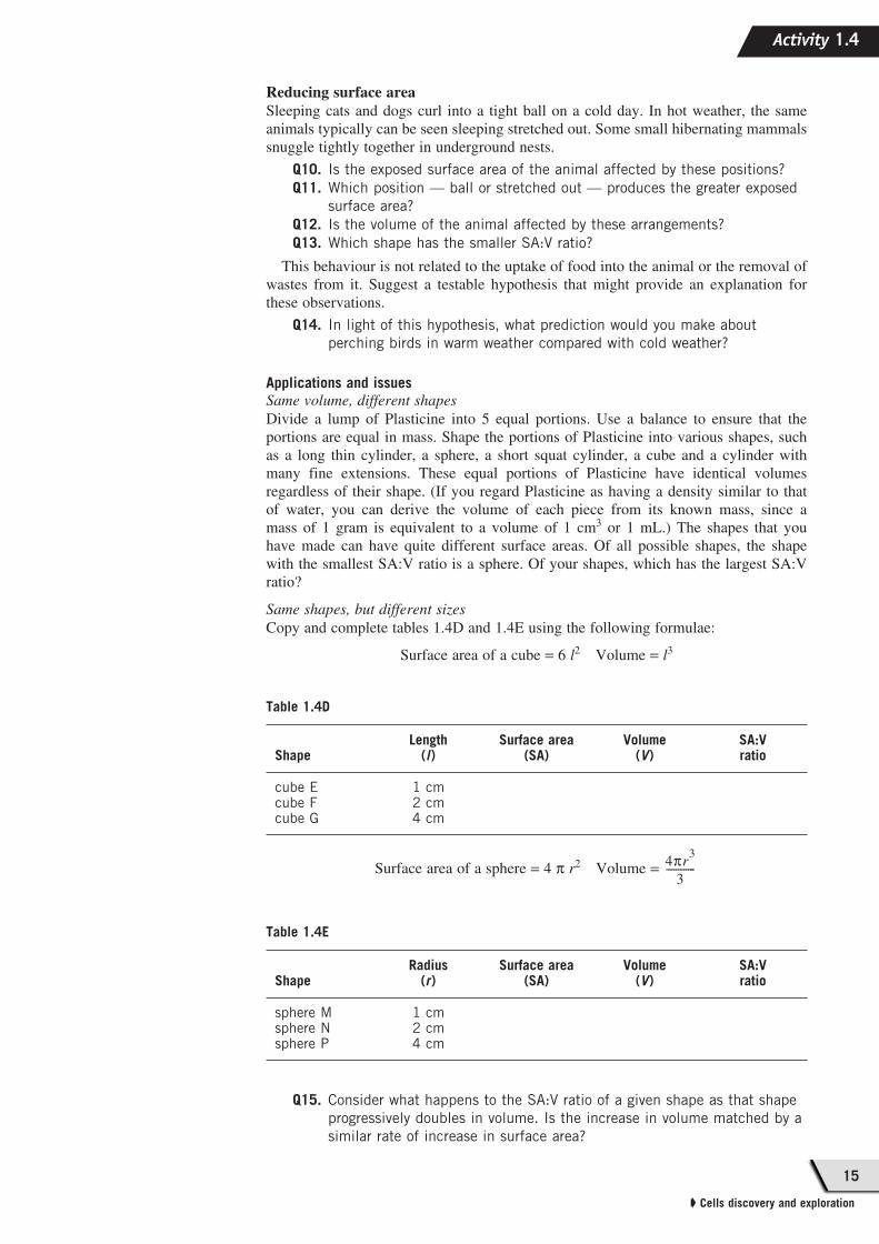
Same shapes, but different sizesCopy and complete tables 1.4D and 1.4E using the following formulae:
Surface area of a cube = 6 l2 Volume = l3
Surface area of a sphere = 4 π r2 Volume =
Q15. Consider what happens to the SA:V ratio of a given shape as that shape
progressively doubles in volume. Is the increase in volume matched by a
similar rate of increase in surface area?
Table 1.4D
ShapeLength
(l)Surface area
(SA)Volume
(V)SA:Vratio
cube Ecube Fcube G
1 cm2 cm4 cm
Table 1.4E
ShapeRadius
(r)Surface area
(SA)Volume
(V)SA:Vratio
sphere Msphere Nsphere P
1 cm2 cm4 cm
4πr3
3------------
Activity 1.4
16
NATURE OF BIOLOGY BOOK 1 THIRD EDITION ACTIVITY MANUAL ➧
Ch
ap
ter
1
In review
Select the most appropriate alternative for each of the
following four questions.
1. Four structures were measured. Which of the
following lists them from smallest to largest?
(a) 0.25 μm, 0.25nm, 0.25 mm, 0.25 m
(b) 0.25 nm, 0.25mm, 0.25 μm, 0.25 m
(c) 0.25 μm, 0.25nm, 0.25 mm, 0.25 μm
(d) 0.25 nm, 0.25 μm, 0.25 mm, 0.25 m
2. The following microscope uses a different source
other than light to view the image:
(a) differential interference contrast
(b) scanning electron microscope
(c) phase contrast microscope
(d) confocal microscope.
3. The capacity of a microscope to resolve refers to
its ability to:
(a) enlarge
(b) brighten
(c) separate into components
(d) give a three-dimensional view.
4. To visualise a cell organelle that is 0.005μm,
which is the best microscope to use?
(a) a compound microscope
(b) a scanning confocal microscope
(c) an electron microscope
(d) a fluorescent microscope
5. Match each of the year(s) in column X with the
relevant scientific discovery in column Y.
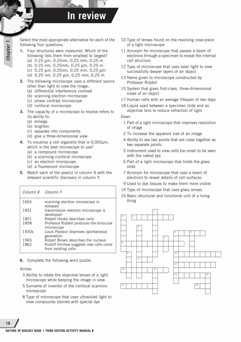
6. Complete the following word puzzle.
Across
3 Ability to rotate the objective lenses of a light
microscope while keeping the image in view
5 Surname of inventor of the confocal scanninc
microscope
8 Type of microscope that uses ultraviolet light to
view compounds stained with special dye
10 Type of lenses found on the revolving nose-piece
of a light microscope
11 Acronym for microscope that passes a beam of
electrons through a specimen to reveal the internal
cell structure
12 Type of microscope that uses laser light to view
successfully deeper layers of an object
13 Name given to microscope constructed by
Professor Riddell
15 System that gives first-class, three-dimensional
views of an object
17 Human cells with an average lifespan of two days
18 Liquid used between a specimen slide and an
objective lens to reduce refraction of light
Down
1 Part of a light microscope that improves resolution
of image
2 To increase the apparent size of an image
4 Ability to see two points that are close together as
two separate points
5 Instrument used to view cells too small to be seen
with the naked eye
6 Part of a light microscope that holds the glass
slide
7 Acronym for microscope that uses a beam of
electrons to reveal details of cell surfaces
9 Used to dye tissues to make them more visible
14 Type of microscope that uses glass lenses
16 Basic structural and functional unit of a living
thing
Column X Column Y
1665
1831
18511858
1930s
19651862
scanning electron microscope is releasedtransmission electron microscope is developedRobert Hooke describes cellsProfessor Riddell produces the binocular microscopeLouis Pasteur disproves spontaneous generationRobert Brown describes the nucleusRudolf Virchow suggests new cells come from existing cells
1
2 3
4
5 6
7
8
9 10
11
12
13 14
15 16
17 18