Embed Size (px)
Citation preview
CHAPTER 1
Catalytic reactor types and their industrialsignificance
Zeynep Ilsen Önsan and Ahmet Kerim AvciDepartment of Chemical Engineering, Boğaziçi University, Istanbul, Turkey
Abstract
The present chapter is aimed to provide a simplified overview ofthe catalytic reactors used in chemical industry. Each reactor typeis described in terms of its key geometric properties, operatingcharacteristics, advantages, and drawbacks among its alternativesand typical areasofuse.Thesignificanceof the reactors isexplainedin the context of selected industrial examples. Industrial reactorsthat do not involve the use of solid catalysts are also discussed.
1.1 Introduction
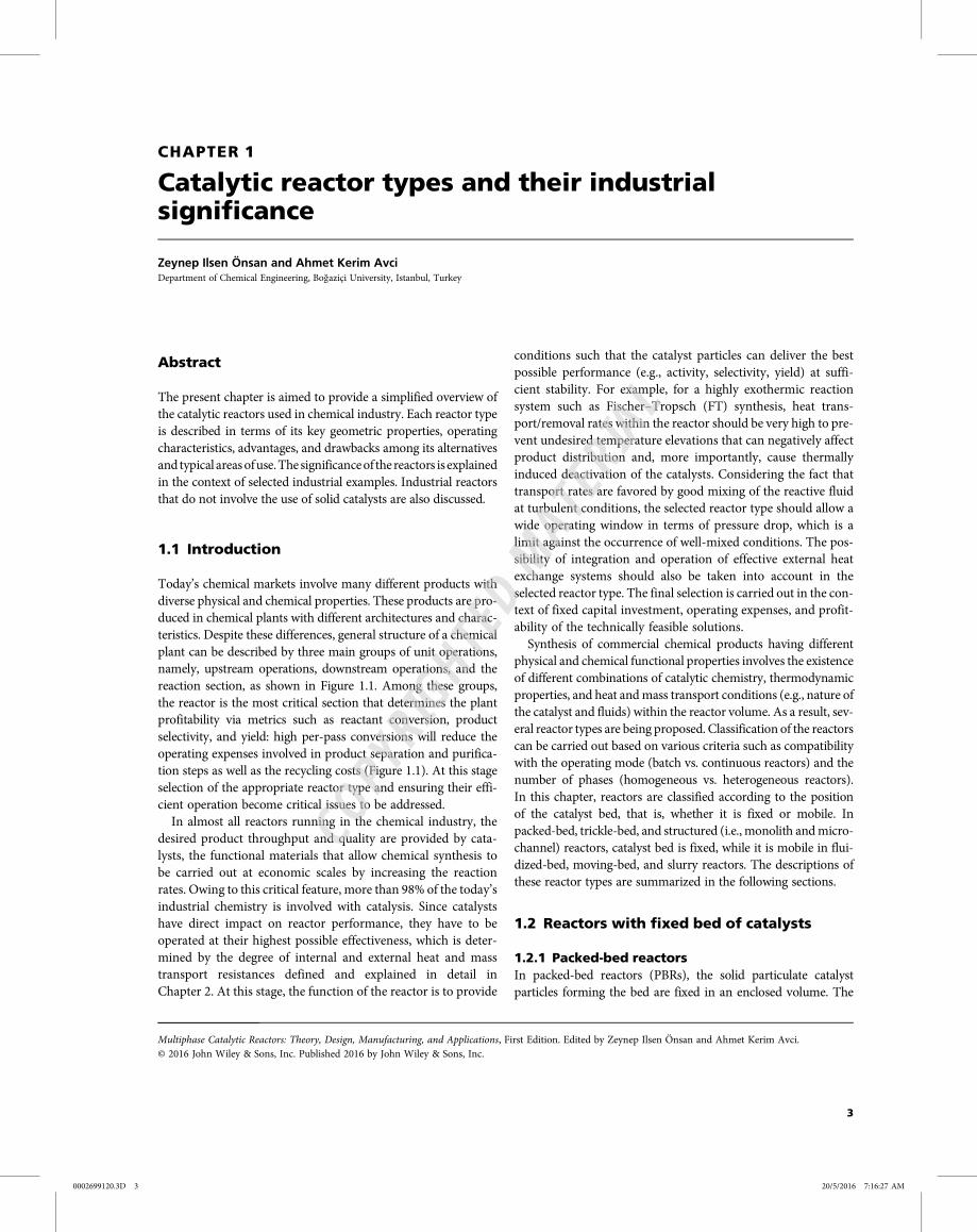
Today’s chemical markets involve many different products withdiverse physical and chemical properties. These products are pro-duced in chemical plants with different architectures and charac-teristics. Despite these differences, general structure of a chemicalplant can be described by three main groups of unit operations,namely, upstream operations, downstream operations, and thereaction section, as shown in Figure 1.1. Among these groups,the reactor is the most critical section that determines the plantprofitability via metrics such as reactant conversion, productselectivity, and yield: high per-pass conversions will reduce theoperating expenses involved in product separation and purifica-tion steps as well as the recycling costs (Figure 1.1). At this stageselection of the appropriate reactor type and ensuring their effi-cient operation become critical issues to be addressed.
In almost all reactors running in the chemical industry, thedesired product throughput and quality are provided by cata-lysts, the functional materials that allow chemical synthesis tobe carried out at economic scales by increasing the reactionrates. Owing to this critical feature, more than 98% of the today’sindustrial chemistry is involved with catalysis. Since catalystshave direct impact on reactor performance, they have to beoperated at their highest possible effectiveness, which is deter-mined by the degree of internal and external heat and masstransport resistances defined and explained in detail inChapter 2. At this stage, the function of the reactor is to provide
conditions such that the catalyst particles can deliver the bestpossible performance (e.g., activity, selectivity, yield) at suffi-cient stability. For example, for a highly exothermic reactionsystem such as Fischer–Tropsch (FT) synthesis, heat trans-port/removal rates within the reactor should be very high to pre-vent undesired temperature elevations that can negatively affectproduct distribution and, more importantly, cause thermallyinduced deactivation of the catalysts. Considering the fact thattransport rates are favored by good mixing of the reactive fluidat turbulent conditions, the selected reactor type should allow awide operating window in terms of pressure drop, which is alimit against the occurrence of well-mixed conditions. The pos-sibility of integration and operation of effective external heatexchange systems should also be taken into account in theselected reactor type. The final selection is carried out in the con-text of fixed capital investment, operating expenses, and profit-ability of the technically feasible solutions.
Synthesis of commercial chemical products having differentphysical and chemical functional properties involves the existenceof different combinations of catalytic chemistry, thermodynamicproperties, and heat andmass transport conditions (e.g., nature ofthe catalyst and fluids) within the reactor volume. As a result, sev-eral reactor types are being proposed. Classification of the reactorscan be carried out based on various criteria such as compatibilitywith the operating mode (batch vs. continuous reactors) and thenumber of phases (homogeneous vs. heterogeneous reactors).In this chapter, reactors are classified according to the positionof the catalyst bed, that is, whether it is fixed or mobile. Inpacked-bed, trickle-bed, and structured (i.e., monolith andmicro-channel) reactors, catalyst bed is fixed, while it is mobile in flui-dized-bed, moving-bed, and slurry reactors. The descriptions ofthese reactor types are summarized in the following sections.
1.2 Reactors with fixed bed of catalysts
1.2.1 Packed-bed reactorsIn packed-bed reactors (PBRs), the solid particulate catalystparticles forming the bed are fixed in an enclosed volume. The
3
0002699120.3D 3 20/5/2016 7:16:27 AM
Multiphase Catalytic Reactors: Theory, Design, Manufacturing, and Applications, First Edition. Edited by Zeynep Ilsen Önsan and Ahmet Kerim Avci.© 2016 John Wiley & Sons, Inc. Published 2016 by John Wiley & Sons, Inc.
COPYRIG
HTED M
ATERIAL
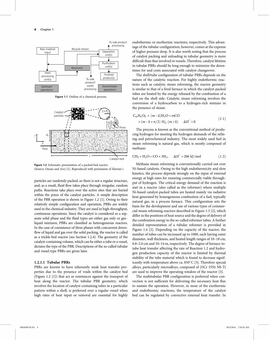
particles are randomly packed, so there is not a regular structure,and, as a result, fluid flow takes place through irregular, randompaths. Reactions take place over the active sites that are buriedwithin the pores of the catalyst particles. A simple descriptionof the PBR operation is shown in Figure 1.2 [1]. Owing to theirrelatively simple configuration and operation, PBRs are widelyused in the chemical industry. They are used in high-throughput,continuous operations. Since the catalyst is considered as a sep-arate solid phase and the fluid types are either gas only or gas–liquid mixtures, PBRs are classified as heterogeneous reactors.In the case of coexistence of three phases with concurrent down-flow of liquid and gas over the solid packing, the reactor is calledas a trickle-bed reactor (see Section 1.2.4). The geometry of thecatalyst-containing volume, which can be either a tube or a vessel,dictates the type of the PBR. Descriptions of the so-called tubularand vessel-type PBRs are given later.
1.2.1.1 Tubular PBRsPBRs are known to have inherently weak heat transfer pro-perties due to the presence of voids within the catalyst bed(Figure 1.2 [1]) that act as resistances against the transport ofheat along the reactor. The tubular PBR geometry, whichinvolves the location of catalyst-containing tubes in a particularpattern within a shell, is preferred over a regular vessel whenhigh rates of heat input or removal are essential for highly
endothermic or exothermic reactions, respectively. This advan-tage of the tubular configuration, however, comes at the expenseof higher pressure drop. It is also worth noting that the processof catalyst packing and unloading in tubular geometry is moredifficult than that involved in vessels. Therefore, catalyst lifetimein tubular PBRs should be long enough to minimize the down-times for and costs associated with catalyst changeover.The shell/tube configuration of tubular PBRs depends on the
nature of the catalytic reaction. For highly endothermic reac-tions such as catalytic steam reforming, the reactor geometryis similar to that of a fired furnace in which the catalyst-packedtubes are heated by the energy released by the combustion of afuel on the shell side. Catalytic steam reforming involves theconversion of a hydrocarbon to a hydrogen-rich mixture inthe presence of steam:
CmHnOk + m – k H2O=mCO
+ m – k+ n 2 H2, m > k ΔH > 01 1
The process is known as the conventional method of produ-cing hydrogen for meeting the hydrogen demands of the refin-ing and petrochemical industry. The most widely used fuel insteam reforming is natural gas, which is mostly composed ofmethane:
CH4 +H2O=CO+ 3H2, ΔH = 206 kJ mol 1 2
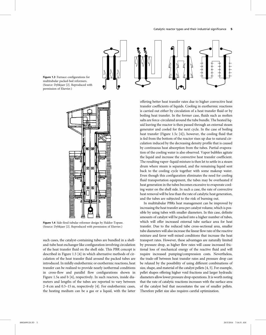
Methane steam reforming is conventionally carried out overNi-based catalysts. Owing to the high endothermicity and slowkinetics, the process depends strongly on the input of externalenergy at high rates for ensuring commercially viable through-put of hydrogen. The critical energy demand of the reaction ismet in a reactor (also called as the reformer) where multipleNi-based catalyst-packed tubes are heated mainly via radiativeheat generated by homogeneous combustion of a fuel, typicallynatural gas, in a process furnace. This configuration sets thebasis for the development and use of various types of commer-cial steam reforming reactors described in Figure 1.3 [2], whichdiffer in the positions of heat source and the degree of delivery ofthe combustion energy to the so-called reformer tubes. A furtherdetailed representation of a tubular reformer is provided inFigure 1.4 [2]. Depending on the capacity of the reactor, thenumber of tubes can be increased up to 1000, each having outerdiameter, wall thickness, and heated length ranges of 10–18 cm,0.8–2.0 cm and 10–14 m, respectively. The degree of furnace-to-tube heat transfer affecting the rate of Reaction 1.2 and hydro-gen production capacity of the reactor is limited by thermalstability of the tube material which is found to decrease signif-icantly with temperature above ca. 850 C [3]. Therefore specialalloys, particularly microalloys, composed of 25Cr 35Ni Nb Tiare used to improve the operating window of the reactor [3].The multitubular PBR configuration is preferred when con-
vection is not sufficient for delivering the necessary heat fluxto sustain the operation. However, in most of the exothermicand endothermic reactions, the temperature of the catalystbed can be regulated by convective external heat transfer. In
Raw materialinput
Feedprocessing
unit(s)
Upstreamoperations
Recycle stream
To side productprocessing
To sideproduct/waste
processingDownstreamoperations
Finishedproduct(s)
Purificationunit(s)
Separationunit(s)
Reactor(s)
Figure 1.1 Outline of a chemical process.
Catalystparticles
Pores
ξ =Rp
Catalyst bedL
Flow
Rtr
z
Figure 1.2 Schematic presentation of a packed-bed reactor.(Source: Onsan and Avci [1]. Reproduced with permission of Elsevier.)
4 Chapter 1
0002699120.3D 4 20/5/2016 7:16:29 AM
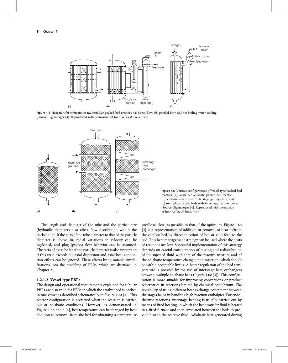
such cases, the catalyst-containing tubes are bundled in a shell-and-tube heat exchanger like configuration involving circulationof the heat transfer fluid on the shell side. This PBR concept isdescribed in Figure 1.5 [4] in which alternative methods of cir-culation of the heat transfer fluid around the packed tubes areintroduced. Inmildly endothermic or exothermic reactions, heattransfer can be realized to provide nearly isothermal conditionsin cross-flow and parallel flow configurations shown inFigure 1.5a and b [4], respectively. In such reactors, inside dia-meters and lengths of the tubes are reported to vary between2–8 cm and 0.5–15 m, respectively [4]. For endothermic cases,the heating medium can be a gas or a liquid, with the latter
offering better heat transfer rates due to higher convective heattransfer coefficients of liquids. Cooling in exothermic reactionsis carried out either by circulation of a heat transfer fluid or byboiling heat transfer. In the former case, fluids such as moltensalts are force-circulated around the tube bundle. The heated liq-uid leaving the reactor is then passed through an external steamgenerator and cooled for the next cycle. In the case of boilingheat transfer (Figure 1.5c [4]), however, the cooling fluid thatis fed from the bottom of the reactor rises up due to natural cir-culation induced by the decreasing density profile that is causedby continuous heat absorption from the tubes. Partial evapora-tion of the cooling water is also observed. Vapor bubbles agitatethe liquid and increase the convective heat transfer coefficient.The resulting vapor–liquid mixture is then let to settle in a steamdrum where steam is separated, and the remaining liquid sentback to the cooling cycle together with some makeup water.Even though this configuration eliminates the need for coolingfluid transportation equipment, the tubes may be overheated ifheat generation in the tubes becomes excessive to evaporate cool-ing water on the shell side. In such a case, the rate of convectiveheat removal will be less than the rate of catalytic heat generation,and the tubes are subjected to the risk of burning out.
In multitubular PBRs heat management can be improved byincreasing the heat transfer area per catalyst volume, which is pos-sible by using tubes with smaller diameters. In this case, definiteamounts of catalyst will be packed into a higher number of tubes,which will offer increased external tube surface area for heattransfer. Due to the reduced tube cross-sectional area, smallertube diameters will also increase the linear flow rate of the reactivemixture and favor well-mixed conditions that increase the heattransport rates. However, these advantages are naturally limitedby pressure drop, as higher flow rates will cause increased fric-tional loss of mechanical energy of the reactive fluid and willrequire increased pumping/compression costs. Nevertheless,the trade-off between heat transfer rates and pressure drop canbe relaxed by the possibility of using different combinations ofsize, shape, and material of the catalyst pellets [4, 5]. For example,pellet shapes offering higher void fractions and larger hydraulicdiameters allow lower pressure drop operations. It is worth notingthat the rate of catalytic reactions increases with the surface areaof the catalyst bed that necessitates the use of smaller pellets.Therefore pellet size also requires careful optimization.
Figure 1.3 Furnace configurations formultitubular packed-bed reformers.(Source: Dybkjaer [2]. Reproduced withpermission of Elsevier.)
Figure 1.4 Side-fired tubular reformer design by Haldor-Topsøe.(Source: Dybkjaer [2]. Reproduced with permission of Elsevier.)
Catalytic reactor types and their industrial significance 5
0002699120.3D 5 20/5/2016 7:16:31 AM
The length and diameter of the tube and the particle size(hydraulic diameter) also affect flow distribution within thepacked tube. If the ratio of the tube diameter to that of the particlediameter is above 30, radial variations in velocity can beneglected, and plug (piston) flow behavior can be assumed.The ratio of the tube length to particle diameter is also important;if this ratio exceeds 50, axial dispersion and axial heat conduc-tion effects can be ignored. These effects bring notable simpli-fications into the modeling of PBRs, which are discussed inChapter 3.
1.2.1.2 Vessel-type PBRsThe design and operational requirements explained for tubularPBRs are also valid for PBRs in which the catalyst bed is packedin one vessel as described schematically in Figure 1.6a [4]. Thisreactor configuration is preferred when the reaction is carriedout at adiabatic conditions. However, as demonstrated inFigure 1.6b and c [4], bed temperature can be changed by heataddition to/removal from the bed for obtaining a temperature
profile as close as possible to that of the optimum. Figure 1.6b[4] is a representation of addition or removal of heat to/fromthe catalyst bed by direct injection of hot or cold feed to thebed. This heat management strategy can be used where the heatsof reactions are low. Successful implementation of this strategydepends on careful consideration of mixing and redistributionof the injected fluid with that of the reactive mixture and ofthe adiabatic temperature change upon injection, which shouldbe within acceptable limits. A better regulation of the bed tem-perature is possible by the use of interstage heat exchangersbetween multiple adiabatic beds (Figure 1.6c [4]). This configu-ration is more suitable for improving conversions or productselectivities in reactions limited by chemical equilibrium. Thepossibility of using different heat exchange equipment betweenthe stages helps in handling high reaction enthalpies. For endo-thermic reactions, interstage heating is usually carried out bymeans of fired heating, in which the heat transfer fluid is heatedin a fired furnace and then circulated between the beds to pro-vide heat to the reactive fluid. Adiabatic heat generated during
Circulationturbine
Steamgenerator
Feedwater
Steam
Feed gas Saturatedsteam
Steam drum
Feedwater
(a) (b) (c)
Figure 1.5 Heat transfer strategies in multitubular packed-bed reactors. (a) Cross-flow, (b) parallel flow, and (c) boiling-water cooling.(Source: Eigenberger [4]. Reproduced with permission of John Wiley & Sons, Inc.)
Interstagegas feed
Feed gas
Interstageheatexchangers
(a) (b) (c)
Figure 1.6 Various configurations of vessel-type packed-bedreactors. (a) Single-bed adiabatic packed-bed reactor,(b) adiabatic reactor with interstage gas injection, and(c) multiple adiabatic beds with interstage heat exchange.(Source: Eigenberger [4]. Reproduced with permissionof John Wiley & Sons, Inc.)
6 Chapter 1
0002699120.3D 6 20/5/2016 7:16:33 AM
exothermic reactions is removed by contacting the hot bed efflu-ent with interstage heat exchange tubes in which a coolant, forexample, water, is circulated for steam generation purposes.
Multiple adiabatic beds with interstage heat exchange config-uration compete with tubular PBR geometry, as both configura-tions provide regulation of the bed temperature to improvereactant conversion and product selectivity. In this respect,the tubular PBR alternative is better, because it offers continuouscontrol over the bed temperature. However, although tempera-ture regulation is only possible through a stepwise pattern in themultiple adiabatic beds, they do offer several practical advan-tages such as the possibility of (i) changing the catalyst bed inindividual stages at different times, (ii) distributed stagewisefeeding of a reactant instead of its total feeding at the inlet,and (iii) drawing a limiting product from an intermediate stagein case of reactions limited by equilibrium [4, 5].
Vessel-type PBRs are widely used in chemical industry.A descriptive example is ammonia synthesis, which is an exo-thermic equilibrium reaction:
N2 + 3H2 = 2NH3, ΔH = −92 4 kJ mol 1 3
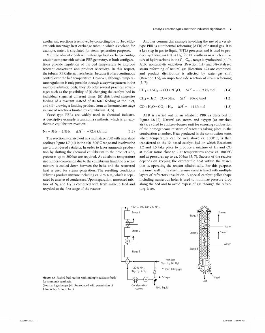
The reaction is carried out in a multistage PBR with interstagecooling (Figure 1.7 [4]) in the 400–500 C range and involves theuse of iron-based catalysts. In order to favor ammonia produc-tion by shifting the chemical equilibrium to the product side,pressures up to 300 bar are required. As adiabatic temperaturerise hinders conversion due to the equilibrium limit, the reactivemixture is cooled down between the beds, and the recoveredheat is used for steam generation. The resulting conditionsdeliver a product mixture including ca. 20% NH3 which is sepa-rated by a series of condensers. Upon separation, unreacted mix-ture of N2 and H2 is combined with fresh makeup feed andrecycled to the first stage of the reactor.
Another commercial example involving the use of a vessel-type PBR is autothermal reforming (ATR) of natural gas. It isa key step in gas-to-liquid (GTL) processes and is used to pro-duce synthesis gas (CO +H2) for FT synthesis in which a mix-ture of hydrocarbons in the C1–C30+ range is synthesized [6]. InATR, noncatalytic oxidation (Reaction 1.4) and Ni-catalyzedsteam reforming of natural gas (Reaction 1.2) are combined,and product distribution is affected by water–gas shift(Reaction 1.5), an important side reaction of steam reforming[3, 7]:
CH4 + 1 5O2 CO+ 2H2O, ΔH = −519 kJ mol 1 4
CH4 +H2O=CO+ 3H2, ΔH = 206 kJ mol 1 2
CO+H2O=CO2 +H2, ΔH = −41 kJ mol 1 5
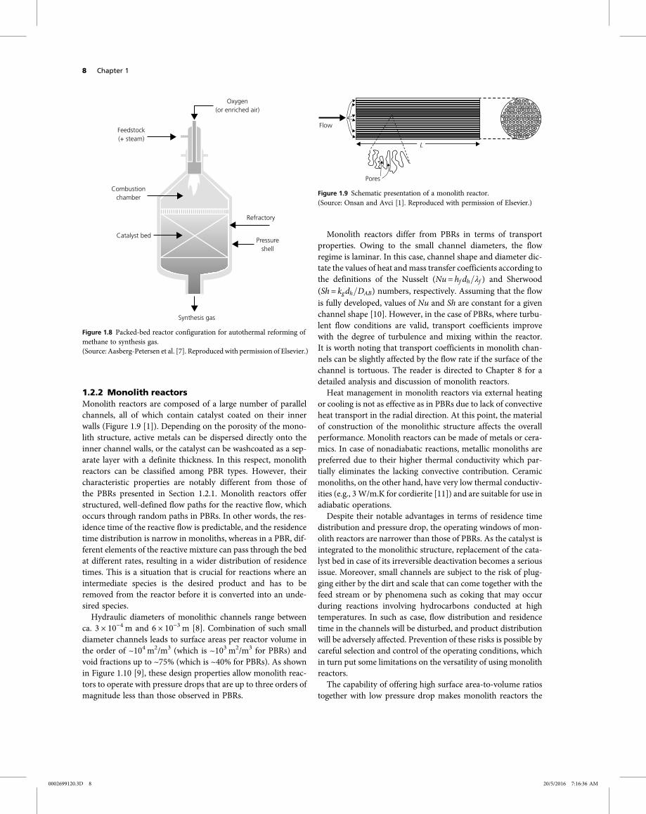
ATR is carried out in an adiabatic PBR as described inFigure 1.8 [7]. Natural gas, steam, and oxygen (or enrichedair) are cofed to a mixer–burner unit for ensuring combustionof the homogeneous mixture of reactants taking place in thecombustion chamber. Heat produced in the combustion zone,where temperature can be well above ca. 1500 C, is thentransferred to the Ni-based catalyst bed on which Reactions1.2 and 1.5 take place to produce a mixture of H2 and COat molar ratios close to 2 at temperatures above ca. 1000 Cand at pressures up to ca. 30 bar [3, 7]. Success of the reactordepends on keeping the exothermic heat within the vessel,that is, operating the reactor adiabatically. For this purpose,the inner wall of the steel pressure vessel is lined with multiplelayers of refractory insulation. A special catalyst pellet shapeincluding numerous holes is used to minimize pressure dropalong the bed and to avoid bypass of gas through the refrac-tory layer.
400°C, 300 bar, 2% NH3
Stage 1Stage 1
Steam
Water
Steam
Water
FeedExit
Stage 2Stage 2
Stage 3Stage 3
20% NH3(N2, H2, CH4)
Circulating gas
Off-gas
NH3, liquid
Fresh gasN2+ 3H2 (+CH4)
Condensationcoolers
Figure 1.7 Packed-bed reactor with multiple adiabatic bedsfor ammonia synthesis.(Source: Eigenberger [4]. Reproduced with permission ofJohn Wiley & Sons, Inc.)
Catalytic reactor types and their industrial significance 7
0002699120.3D 7 20/5/2016 7:16:35 AM
1.2.2 Monolith reactorsMonolith reactors are composed of a large number of parallelchannels, all of which contain catalyst coated on their innerwalls (Figure 1.9 [1]). Depending on the porosity of the mono-lith structure, active metals can be dispersed directly onto theinner channel walls, or the catalyst can be washcoated as a sep-arate layer with a definite thickness. In this respect, monolithreactors can be classified among PBR types. However, theircharacteristic properties are notably different from those ofthe PBRs presented in Section 1.2.1. Monolith reactors offerstructured, well-defined flow paths for the reactive flow, whichoccurs through random paths in PBRs. In other words, the res-idence time of the reactive flow is predictable, and the residencetime distribution is narrow in monoliths, whereas in a PBR, dif-ferent elements of the reactive mixture can pass through the bedat different rates, resulting in a wider distribution of residencetimes. This is a situation that is crucial for reactions where anintermediate species is the desired product and has to beremoved from the reactor before it is converted into an unde-sired species.Hydraulic diameters of monolithic channels range between
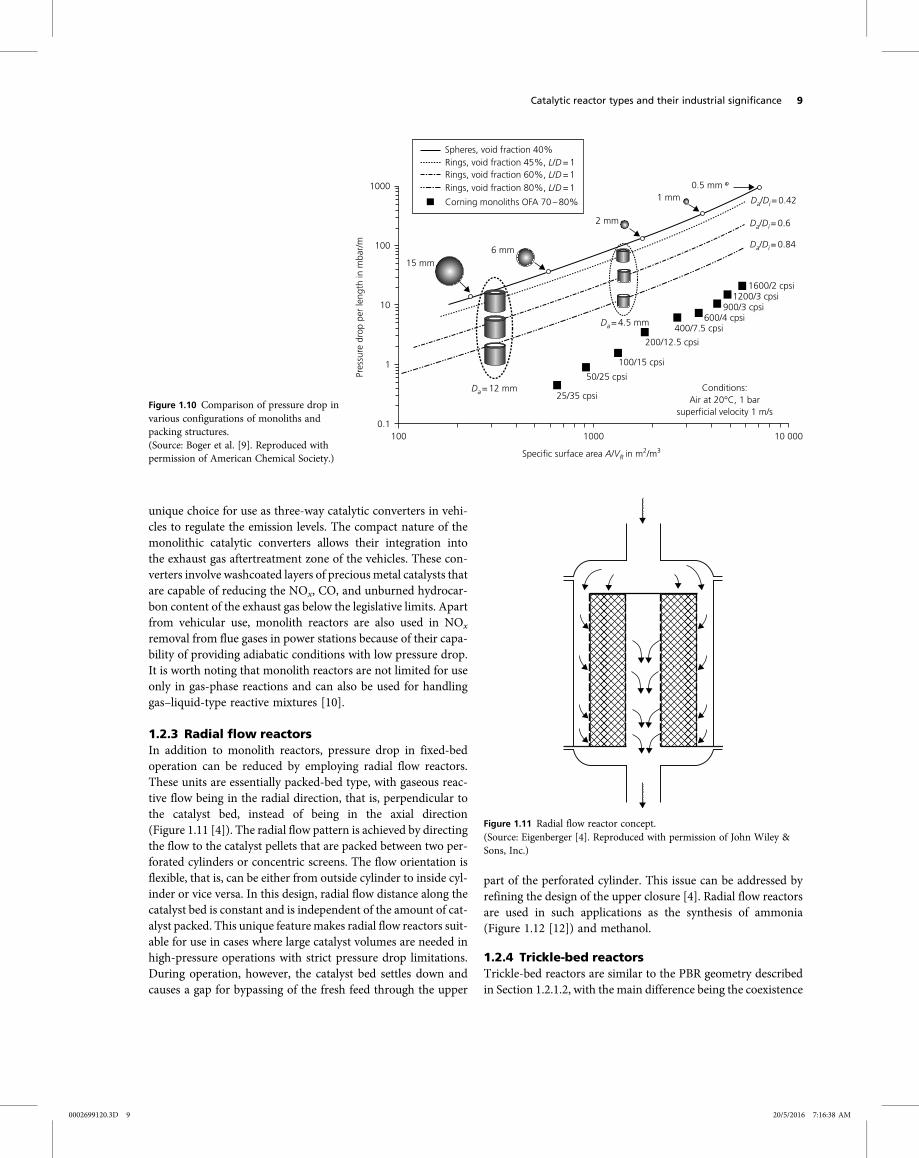
ca. 3 × 10⁻⁴ m and 6 × 10⁻³ m [8]. Combination of such smalldiameter channels leads to surface areas per reactor volume inthe order of ~104 m2/m3 (which is ~103 m2/m3 for PBRs) andvoid fractions up to ~75% (which is ~40% for PBRs). As shownin Figure 1.10 [9], these design properties allow monolith reac-tors to operate with pressure drops that are up to three orders ofmagnitude less than those observed in PBRs.
Monolith reactors differ from PBRs in terms of transportproperties. Owing to the small channel diameters, the flowregime is laminar. In this case, channel shape and diameter dic-tate the values of heat andmass transfer coefficients according tothe definitions of the Nusselt (Nu= hf dh λf ) and Sherwood(Sh = kgdh DAB) numbers, respectively. Assuming that the flowis fully developed, values of Nu and Sh are constant for a givenchannel shape [10]. However, in the case of PBRs, where turbu-lent flow conditions are valid, transport coefficients improvewith the degree of turbulence and mixing within the reactor.It is worth noting that transport coefficients in monolith chan-nels can be slightly affected by the flow rate if the surface of thechannel is tortuous. The reader is directed to Chapter 8 for adetailed analysis and discussion of monolith reactors.Heat management in monolith reactors via external heating
or cooling is not as effective as in PBRs due to lack of convectiveheat transport in the radial direction. At this point, the materialof construction of the monolithic structure affects the overallperformance. Monolith reactors can be made of metals or cera-mics. In case of nonadiabatic reactions, metallic monoliths arepreferred due to their higher thermal conductivity which par-tially eliminates the lacking convective contribution. Ceramicmonoliths, on the other hand, have very low thermal conductiv-ities (e.g., 3 W/m.K for cordierite [11]) and are suitable for use inadiabatic operations.Despite their notable advantages in terms of residence time
distribution and pressure drop, the operating windows of mon-olith reactors are narrower than those of PBRs. As the catalyst isintegrated to the monolithic structure, replacement of the cata-lyst bed in case of its irreversible deactivation becomes a seriousissue. Moreover, small channels are subject to the risk of plug-ging either by the dirt and scale that can come together with thefeed stream or by phenomena such as coking that may occurduring reactions involving hydrocarbons conducted at hightemperatures. In such as case, flow distribution and residencetime in the channels will be disturbed, and product distributionwill be adversely affected. Prevention of these risks is possible bycareful selection and control of the operating conditions, whichin turn put some limitations on the versatility of using monolithreactors.The capability of offering high surface area-to-volume ratios
together with low pressure drop makes monolith reactors the
Feedstock(+ steam)
Combustionchamber
Catalyst bed
Synthesis gas
Pressureshell
Refractory
Oxygen(or enriched air)
Figure 1.8 Packed-bed reactor configuration for autothermal reforming ofmethane to synthesis gas.(Source: Aasberg-Petersen et al. [7]. Reproduced with permission of Elsevier.)
Flow
Pores
L
Figure 1.9 Schematic presentation of a monolith reactor.(Source: Onsan and Avci [1]. Reproduced with permission of Elsevier.)
8 Chapter 1
0002699120.3D 8 20/5/2016 7:16:36 AM
unique choice for use as three-way catalytic converters in vehi-cles to regulate the emission levels. The compact nature of themonolithic catalytic converters allows their integration intothe exhaust gas aftertreatment zone of the vehicles. These con-verters involve washcoated layers of precious metal catalysts thatare capable of reducing the NOx, CO, and unburned hydrocar-bon content of the exhaust gas below the legislative limits. Apartfrom vehicular use, monolith reactors are also used in NOx
removal from flue gases in power stations because of their capa-bility of providing adiabatic conditions with low pressure drop.It is worth noting that monolith reactors are not limited for useonly in gas-phase reactions and can also be used for handlinggas–liquid-type reactive mixtures [10].
1.2.3 Radial flow reactorsIn addition to monolith reactors, pressure drop in fixed-bedoperation can be reduced by employing radial flow reactors.These units are essentially packed-bed type, with gaseous reac-tive flow being in the radial direction, that is, perpendicular tothe catalyst bed, instead of being in the axial direction(Figure 1.11 [4]). The radial flow pattern is achieved by directingthe flow to the catalyst pellets that are packed between two per-forated cylinders or concentric screens. The flow orientation isflexible, that is, can be either from outside cylinder to inside cyl-inder or vice versa. In this design, radial flow distance along thecatalyst bed is constant and is independent of the amount of cat-alyst packed. This unique featuremakes radial flow reactors suit-able for use in cases where large catalyst volumes are needed inhigh-pressure operations with strict pressure drop limitations.During operation, however, the catalyst bed settles down andcauses a gap for bypassing of the fresh feed through the upper
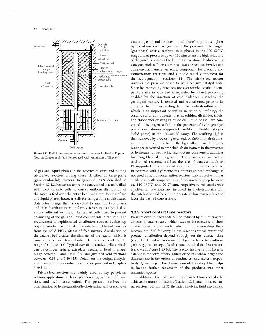
part of the perforated cylinder. This issue can be addressed byrefining the design of the upper closure [4]. Radial flow reactorsare used in such applications as the synthesis of ammonia(Figure 1.12 [12]) and methanol.
1.2.4 Trickle-bed reactorsTrickle-bed reactors are similar to the PBR geometry describedin Section 1.2.1.2, with the main difference being the coexistence
1000
100
10
1
0.1100 1000
Specific surface area A/VR in m2/m3
Pres
sure
dro
p pe
r le
ngth
in m
bar/
m
10 000
Spheres, void fraction 40%Rings, void fraction 45%, L/D= 1Rings, void fraction 60%, L/D= 1Rings, void fraction 80%, L/D= 1
Corning monoliths OFA 70 – 80%
15 mm6 mm
2 mm
1 mm0.5 mm
Da/Di= 0.42
Da/Di= 0.6
Da/Di= 0.84
Da= 12 mm25/35 cpsi
50/25 cpsiConditions:
Air at 20°C, 1 barsuperficial velocity 1 m/s
100/15 cpsi
200/12.5 cpsi
400/7.5 cpsi600/4 cpsi
900/3 cpsi1200/3 cpsi
1600/2 cpsi
Da= 4.5 mm
Figure 1.10 Comparison of pressure drop invarious configurations of monoliths andpacking structures.(Source: Boger et al. [9]. Reproduced withpermission of American Chemical Society.)
Figure 1.11 Radial flow reactor concept.(Source: Eigenberger [4]. Reproduced with permission of John Wiley &Sons, Inc.)
Catalytic reactor types and their industrial significance 9
0002699120.3D 9 20/5/2016 7:16:38 AM
of gas and liquid phases in the reactive mixture and puttingtrickle-bed reactors among those classified as three-phase(gas–liquid–solid) reactors. In gas–solid PBRs described inSection 1.2.1.2, headspace above the catalyst bed is usually filledwith inert ceramic balls to ensure uniform distribution ofthe gaseous feed over the entire bed. Cocurrent feeding of gasand liquid phases, however, calls for using a more sophisticateddistributor design that is expected to mix the two phasesand then distribute them uniformly across the catalyst bed toensure sufficient wetting of the catalyst pellets and to preventchanneling of the gas and liquid components in the feed. Therequirement of sophisticated distributors such as bubble captrays is another factor that differentiates trickle-bed reactorsfrom gas–solid PBRs. Status of feed mixture distribution tothe catalyst bed dictates the diameter of the reactor, which isusually under 5 m. Height-to-diameter ratio is usually in therange of 5 and 25 [13]. Typical sizes of the catalyst pellets, whichcan be cylinder, sphere, extrudate, needle, or bead in shape,range between 1 and 5 × 10⁻³ m and give bed void fractionsbetween ~0.35 and 0.40 [13]. Details on the design, analysis,and operation of trickle-bed reactors are provided in Chapters5 and 13.Trickle-bed reactors are mainly used in key petroleum
refining applications such as hydrocracking, hydrodesulfuriza-tion, and hydroisomerization. The process involves thecombination of hydrogenation/hydrotreating and cracking of
vacuum gas oil and residues (liquid phase) to produce lighterhydrocarbons such as gasoline in the presence of hydrogen(gas phase) over a catalyst (solid phase) in the 300–600 Crange and at pressures up to ~150 atm to ensure high solubilityof the gaseous phase in the liquid. Conventional hydrocrakingcatalysts, such as Pt on aluminosilicates or zeolites, involve twocomponents, namely, an acidic component for cracking andisomerization reactions and a noble metal component forthe hydrogenation reactions [14]. The trickle-bed reactorinvolves the presence of up to six successive catalyst beds.Since hydrocracking reactions are exothermic, adiabatic tem-perature rise in each bed is regulated by interstage coolingenabled by the injection of cold hydrogen quenches; thegas–liquid mixture is remixed and redistributed prior to itsentrance to the succeeding bed. In hydrodesulfurization,which is an important operation in crude oil refining, theorganic sulfur components, that is, sulfides, disulfides, thiols,and thiophenes existing in crude oil (liquid phase), are con-verted to hydrogen sulfide in the presence of hydrogen (gasphase) over alumina-supported Co–Mo or Ni–Mo catalysts(solid phase) in the 350–400 C range. The resulting H2S isthen removed by processing over beds of ZnO. In hydroisome-rization, on the other hand, the light alkanes in the C4–C6
range are converted to branched-chain isomers in the presenceof hydrogen for producing high-octane component additivesfor being blended into gasoline. The process, carried out intrickle-bed reactors, involves the use of catalysts such asPt supported on chlorinated alumina or on acidic zeolites.In contrast with hydrocrackers, interstage heat exchange isnot used in hydroisomerization reactors which involve milderconditions, with temperatures and pressures ranging betweenca. 110–180 C and 20–70 atm, respectively. As exothermicequilibrium reactions are involved in hydroisomerization,the catalyst should be able to operate at low temperatures tofavor the desired conversions.
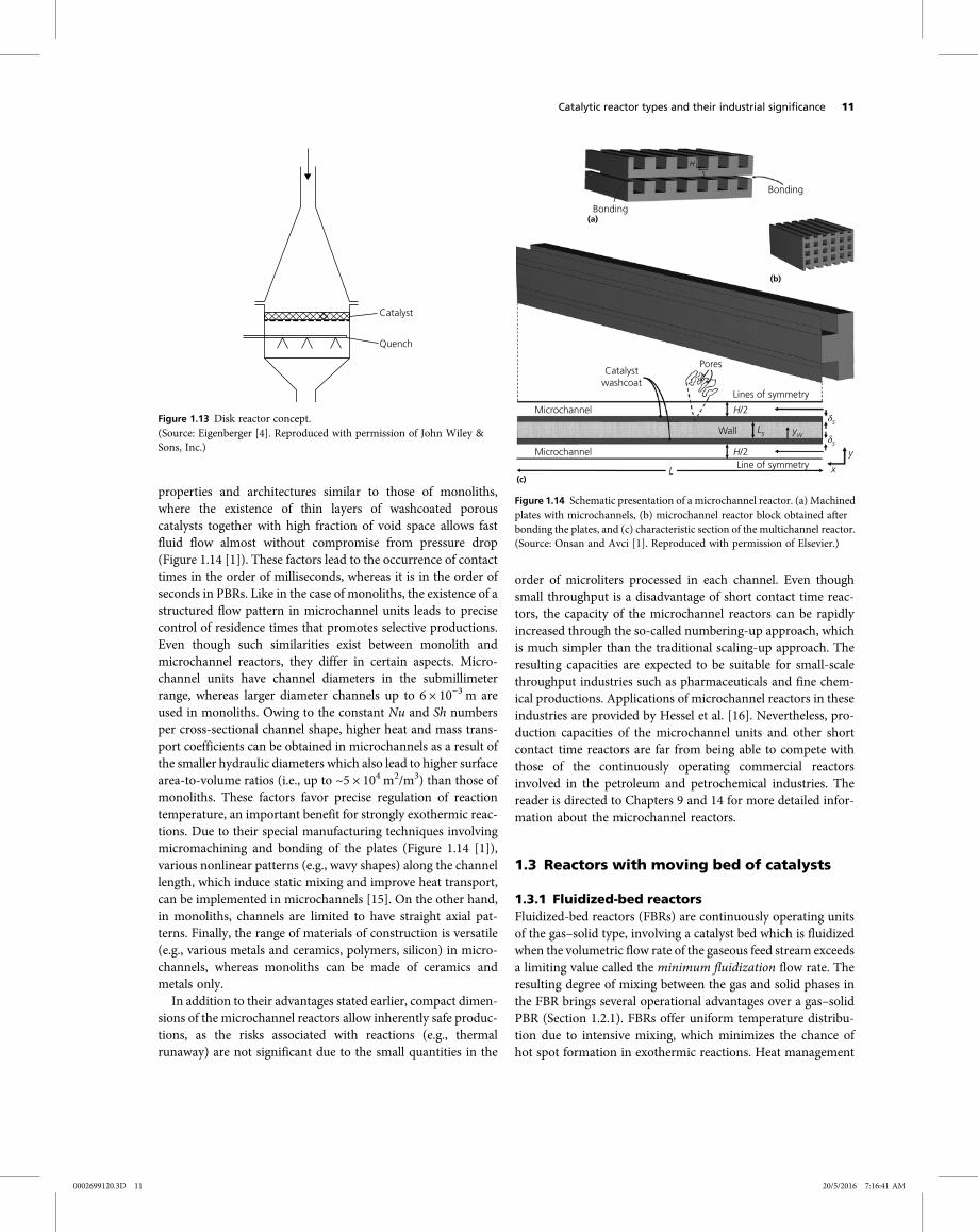
1.2.5 Short contact time reactorsPressure drop in fixed beds can be reduced by minimizing theamount of catalyst used, which leads to the existence of shortcontact times. In addition to reduction of pressure drop, thesereactors are ideal for carrying out reactions whose extent andproduct distribution depend strongly on the contact time(e.g., direct partial oxidation of hydrocarbons to synthesisgas). A typical concept of such a reactor, called the disk reactor,is shown in Figure 1.13 [4]. The reactor involves a thin layer ofcatalyst in the form of wire gauzes or pellets, whose height anddiameter are in the orders of centimeters and meters, respec-tively. Quenching at the downstream of the catalyst bed helpsin halting further conversion of the products into otherunwanted species.In addition to the disk reactor, short contact times can also be
achieved in monolith reactors (Section 1.2.2) and in microchan-nel reactors (Section 1.2.5), the latter involving fluid mechanical
Main inlet
Manhole andcatalyst
loading holes
Shellof internals
Outlet
Cold bypass
Lower exchangers
Transfer tube
Perforatedcenter tube
Innerannular space
Outerannular space
Pressure shell
Innerbasket lid
Outerbasket lid
Ouench
No. 1 bed
No. 2 bed
Figure 1.12 Radial flow ammonia synthesis converter by Haldor-Topsøe.(Source: Couper et al. [12]. Reproduced with permission of Elsevier.)
10 Chapter 1
0002699120.3D 10 20/5/2016 7:16:39 AM
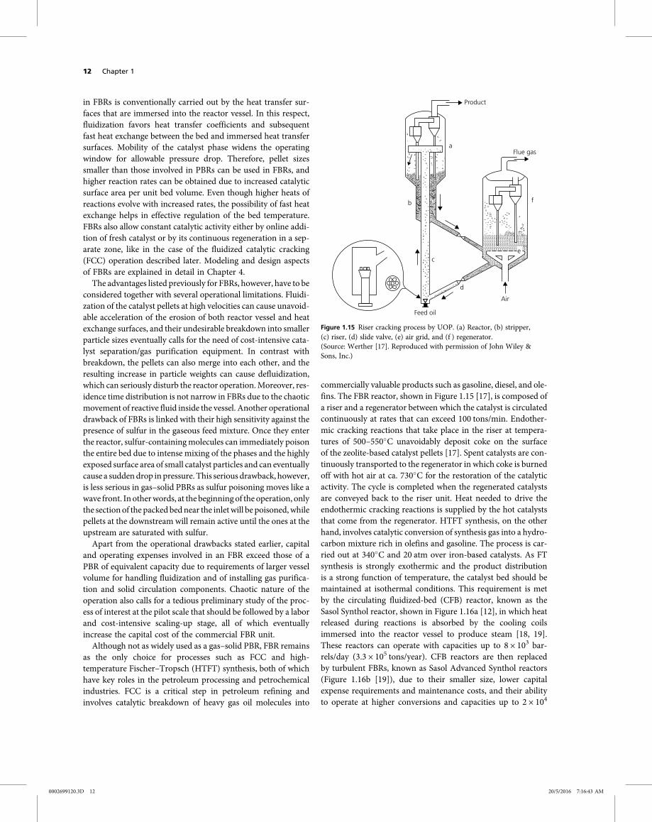
properties and architectures similar to those of monoliths,where the existence of thin layers of washcoated porouscatalysts together with high fraction of void space allows fastfluid flow almost without compromise from pressure drop(Figure 1.14 [1]). These factors lead to the occurrence of contacttimes in the order of milliseconds, whereas it is in the order ofseconds in PBRs. Like in the case of monoliths, the existence of astructured flow pattern in microchannel units leads to precisecontrol of residence times that promotes selective productions.Even though such similarities exist between monolith andmicrochannel reactors, they differ in certain aspects. Micro-channel units have channel diameters in the submillimeterrange, whereas larger diameter channels up to 6 × 10⁻³ m areused in monoliths. Owing to the constant Nu and Sh numbersper cross-sectional channel shape, higher heat and mass trans-port coefficients can be obtained in microchannels as a result ofthe smaller hydraulic diameters which also lead to higher surfacearea-to-volume ratios (i.e., up to ~5 × 10⁴ m2/m3) than those ofmonoliths. These factors favor precise regulation of reactiontemperature, an important benefit for strongly exothermic reac-tions. Due to their special manufacturing techniques involvingmicromachining and bonding of the plates (Figure 1.14 [1]),various nonlinear patterns (e.g., wavy shapes) along the channellength, which induce static mixing and improve heat transport,can be implemented in microchannels [15]. On the other hand,in monoliths, channels are limited to have straight axial pat-terns. Finally, the range of materials of construction is versatile(e.g., various metals and ceramics, polymers, silicon) in micro-channels, whereas monoliths can be made of ceramics andmetals only.
In addition to their advantages stated earlier, compact dimen-sions of the microchannel reactors allow inherently safe produc-tions, as the risks associated with reactions (e.g., thermalrunaway) are not significant due to the small quantities in the
order of microliters processed in each channel. Even thoughsmall throughput is a disadvantage of short contact time reac-tors, the capacity of the microchannel reactors can be rapidlyincreased through the so-called numbering-up approach, whichis much simpler than the traditional scaling-up approach. Theresulting capacities are expected to be suitable for small-scalethroughput industries such as pharmaceuticals and fine chem-ical productions. Applications of microchannel reactors in theseindustries are provided by Hessel et al. [16]. Nevertheless, pro-duction capacities of the microchannel units and other shortcontact time reactors are far from being able to compete withthose of the continuously operating commercial reactorsinvolved in the petroleum and petrochemical industries. Thereader is directed to Chapters 9 and 14 for more detailed infor-mation about the microchannel reactors.
1.3 Reactors with moving bed of catalysts
1.3.1 Fluidized-bed reactorsFluidized-bed reactors (FBRs) are continuously operating unitsof the gas–solid type, involving a catalyst bed which is fluidizedwhen the volumetric flow rate of the gaseous feed stream exceedsa limiting value called the minimum fluidization flow rate. Theresulting degree of mixing between the gas and solid phases inthe FBR brings several operational advantages over a gas–solidPBR (Section 1.2.1). FBRs offer uniform temperature distribu-tion due to intensive mixing, which minimizes the chance ofhot spot formation in exothermic reactions. Heat management
(c)
(b)
Catalystwashcoat
Microchannel
Microchannel
Wall
Line of symmetry xL
y
Lsδsδs
H/2
H/2
HS
yw
Pores
Lines of symmetry
Bonding
Bonding
(a)
Figure 1.14 Schematic presentation of a microchannel reactor. (a) Machinedplates with microchannels, (b) microchannel reactor block obtained afterbonding the plates, and (c) characteristic section of the multichannel reactor.(Source: Onsan and Avci [1]. Reproduced with permission of Elsevier.)
Catalyst
Quench
Figure 1.13 Disk reactor concept.(Source: Eigenberger [4]. Reproduced with permission of John Wiley &Sons, Inc.)
Catalytic reactor types and their industrial significance 11
0002699120.3D 11 20/5/2016 7:16:41 AM
in FBRs is conventionally carried out by the heat transfer sur-faces that are immersed into the reactor vessel. In this respect,fluidization favors heat transfer coefficients and subsequentfast heat exchange between the bed and immersed heat transfersurfaces. Mobility of the catalyst phase widens the operatingwindow for allowable pressure drop. Therefore, pellet sizessmaller than those involved in PBRs can be used in FBRs, andhigher reaction rates can be obtained due to increased catalyticsurface area per unit bed volume. Even though higher heats ofreactions evolve with increased rates, the possibility of fast heatexchange helps in effective regulation of the bed temperature.FBRs also allow constant catalytic activity either by online addi-tion of fresh catalyst or by its continuous regeneration in a sep-arate zone, like in the case of the fluidized catalytic cracking(FCC) operation described later. Modeling and design aspectsof FBRs are explained in detail in Chapter 4.The advantages listed previously for FBRs, however, have to be
considered together with several operational limitations. Fluidi-zation of the catalyst pellets at high velocities can cause unavoid-able acceleration of the erosion of both reactor vessel and heatexchange surfaces, and their undesirable breakdown into smallerparticle sizes eventually calls for the need of cost-intensive cata-lyst separation/gas purification equipment. In contrast withbreakdown, the pellets can also merge into each other, and theresulting increase in particle weights can cause defluidization,which can seriously disturb the reactor operation.Moreover, res-idence time distribution is not narrow in FBRs due to the chaoticmovement of reactive fluid inside the vessel. Another operationaldrawback of FBRs is linked with their high sensitivity against thepresence of sulfur in the gaseous feed mixture. Once they enterthe reactor, sulfur-containingmolecules can immediately poisonthe entire bed due to intense mixing of the phases and the highlyexposed surface area of small catalyst particles and can eventuallycause a suddendrop in pressure. This serious drawback, however,is less serious in gas–solid PBRs as sulfur poisoning moves like awave front. In otherwords, at the beginning of the operation, onlythe section of the packed bednear the inletwill be poisoned, whilepellets at the downstream will remain active until the ones at theupstream are saturated with sulfur.Apart from the operational drawbacks stated earlier, capital
and operating expenses involved in an FBR exceed those of aPBR of equivalent capacity due to requirements of larger vesselvolume for handling fluidization and of installing gas purifica-tion and solid circulation components. Chaotic nature of theoperation also calls for a tedious preliminary study of the proc-ess of interest at the pilot scale that should be followed by a laborand cost-intensive scaling-up stage, all of which eventuallyincrease the capital cost of the commercial FBR unit.Although not as widely used as a gas–solid PBR, FBR remains
as the only choice for processes such as FCC and high-temperature Fischer–Tropsch (HTFT) synthesis, both of whichhave key roles in the petroleum processing and petrochemicalindustries. FCC is a critical step in petroleum refining andinvolves catalytic breakdown of heavy gas oil molecules into
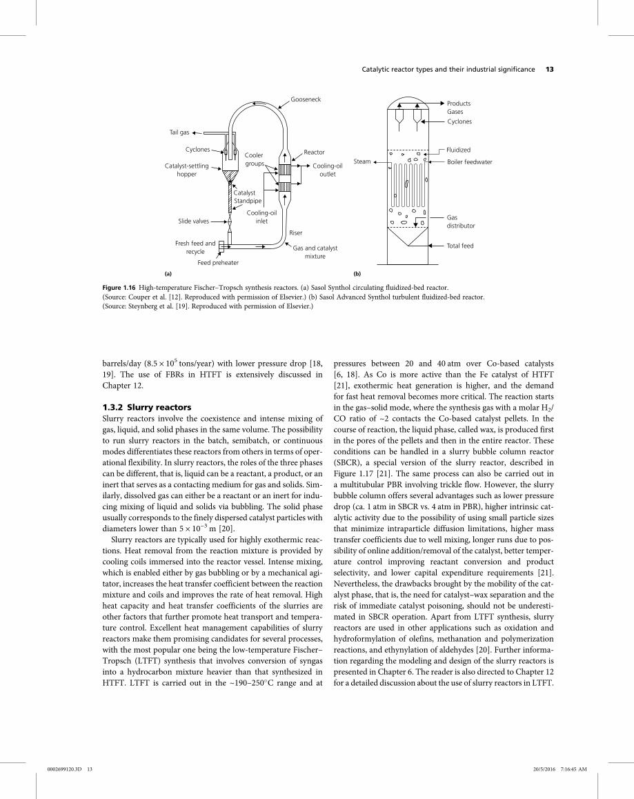
commercially valuable products such as gasoline, diesel, and ole-fins. The FBR reactor, shown in Figure 1.15 [17], is composed ofa riser and a regenerator between which the catalyst is circulatedcontinuously at rates that can exceed 100 tons/min. Endother-mic cracking reactions that take place in the riser at tempera-tures of 500–550 C unavoidably deposit coke on the surfaceof the zeolite-based catalyst pellets [17]. Spent catalysts are con-tinuously transported to the regenerator in which coke is burnedoff with hot air at ca. 730 C for the restoration of the catalyticactivity. The cycle is completed when the regenerated catalystsare conveyed back to the riser unit. Heat needed to drive theendothermic cracking reactions is supplied by the hot catalyststhat come from the regenerator. HTFT synthesis, on the otherhand, involves catalytic conversion of synthesis gas into a hydro-carbon mixture rich in olefins and gasoline. The process is car-ried out at 340 C and 20 atm over iron-based catalysts. As FTsynthesis is strongly exothermic and the product distributionis a strong function of temperature, the catalyst bed should bemaintained at isothermal conditions. This requirement is metby the circulating fluidized-bed (CFB) reactor, known as theSasol Synthol reactor, shown in Figure 1.16a [12], in which heatreleased during reactions is absorbed by the cooling coilsimmersed into the reactor vessel to produce steam [18, 19].These reactors can operate with capacities up to 8 × 10³ bar-rels/day (3.3 × 10⁵ tons/year). CFB reactors are then replacedby turbulent FBRs, known as Sasol Advanced Synthol reactors(Figure 1.16b [19]), due to their smaller size, lower capitalexpense requirements and maintenance costs, and their abilityto operate at higher conversions and capacities up to 2 × 10⁴
Product
a
fb
c
d
Flue gas
e
Feed oil
Air
Figure 1.15 Riser cracking process by UOP. (a) Reactor, (b) stripper,(c) riser, (d) slide valve, (e) air grid, and (f ) regenerator.(Source: Werther [17]. Reproduced with permission of John Wiley &Sons, Inc.)
12 Chapter 1
0002699120.3D 12 20/5/2016 7:16:43 AM
barrels/day (8.5 × 10⁵ tons/year) with lower pressure drop [18,19]. The use of FBRs in HTFT is extensively discussed inChapter 12.
1.3.2 Slurry reactorsSlurry reactors involve the coexistence and intense mixing ofgas, liquid, and solid phases in the same volume. The possibilityto run slurry reactors in the batch, semibatch, or continuousmodes differentiates these reactors from others in terms of oper-ational flexibility. In slurry reactors, the roles of the three phasescan be different, that is, liquid can be a reactant, a product, or aninert that serves as a contacting medium for gas and solids. Sim-ilarly, dissolved gas can either be a reactant or an inert for indu-cing mixing of liquid and solids via bubbling. The solid phaseusually corresponds to the finely dispersed catalyst particles withdiameters lower than 5 × 10⁻³ m [20].
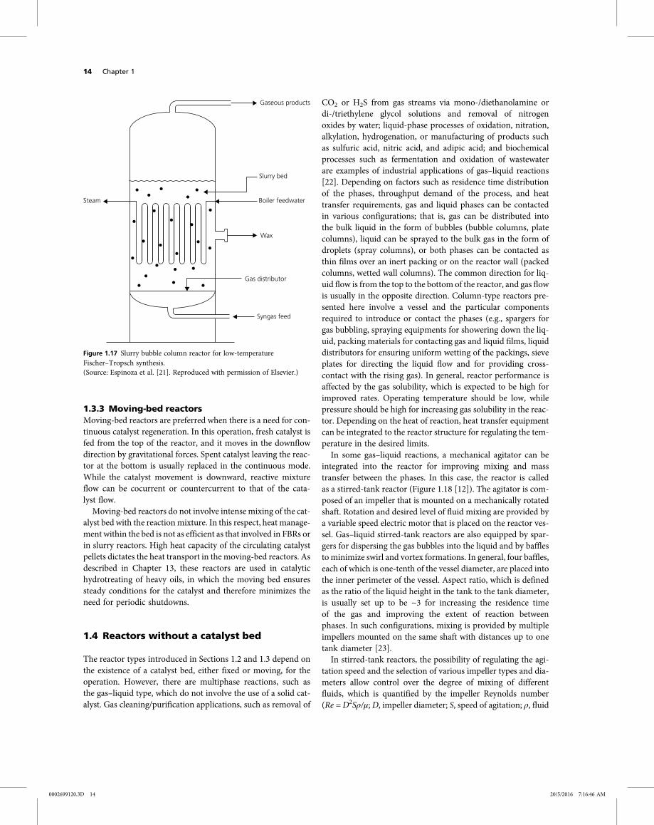
Slurry reactors are typically used for highly exothermic reac-tions. Heat removal from the reaction mixture is provided bycooling coils immersed into the reactor vessel. Intense mixing,which is enabled either by gas bubbling or by a mechanical agi-tator, increases the heat transfer coefficient between the reactionmixture and coils and improves the rate of heat removal. Highheat capacity and heat transfer coefficients of the slurries areother factors that further promote heat transport and tempera-ture control. Excellent heat management capabilities of slurryreactors make them promising candidates for several processes,with the most popular one being the low-temperature Fischer–Tropsch (LTFT) synthesis that involves conversion of syngasinto a hydrocarbon mixture heavier than that synthesized inHTFT. LTFT is carried out in the ~190–250 C range and at
pressures between 20 and 40 atm over Co-based catalysts[6, 18]. As Co is more active than the Fe catalyst of HTFT[21], exothermic heat generation is higher, and the demandfor fast heat removal becomes more critical. The reaction startsin the gas–solid mode, where the synthesis gas with a molar H2/CO ratio of ~2 contacts the Co-based catalyst pellets. In thecourse of reaction, the liquid phase, called wax, is produced firstin the pores of the pellets and then in the entire reactor. Theseconditions can be handled in a slurry bubble column reactor(SBCR), a special version of the slurry reactor, described inFigure 1.17 [21]. The same process can also be carried out ina multitubular PBR involving trickle flow. However, the slurrybubble column offers several advantages such as lower pressuredrop (ca. 1 atm in SBCR vs. 4 atm in PBR), higher intrinsic cat-alytic activity due to the possibility of using small particle sizesthat minimize intraparticle diffusion limitations, higher masstransfer coefficients due to well mixing, longer runs due to pos-sibility of online addition/removal of the catalyst, better temper-ature control improving reactant conversion and productselectivity, and lower capital expenditure requirements [21].Nevertheless, the drawbacks brought by the mobility of the cat-alyst phase, that is, the need for catalyst–wax separation and therisk of immediate catalyst poisoning, should not be underesti-mated in SBCR operation. Apart from LTFT synthesis, slurryreactors are used in other applications such as oxidation andhydroformylation of olefins, methanation and polymerizationreactions, and ethynylation of aldehydes [20]. Further informa-tion regarding the modeling and design of the slurry reactors ispresented in Chapter 6. The reader is also directed to Chapter 12for a detailed discussion about the use of slurry reactors in LTFT.
Tail gas
Cyclones
Catalyst-settlinghopper
Slide valves
Fresh feed andrecycle
Feed preheater
(a) (b)
Gas and catalystmixture
Riser
Reactor
Gooseneck
Cooler groups
CatalystStandpipe
Cooling-oiloutlet
Cooling-oilinlet
Steam
ProductsGases
Cyclones
Fluidized
Boiler feedwater
Gasdistributor
Total feed
Figure 1.16 High-temperature Fischer–Tropsch synthesis reactors. (a) Sasol Synthol circulating fluidized-bed reactor.(Source: Couper et al. [12]. Reproduced with permission of Elsevier.) (b) Sasol Advanced Synthol turbulent fluidized-bed reactor.(Source: Steynberg et al. [19]. Reproduced with permission of Elsevier.)
Catalytic reactor types and their industrial significance 13
0002699120.3D 13 20/5/2016 7:16:45 AM
1.3.3 Moving-bed reactorsMoving-bed reactors are preferred when there is a need for con-tinuous catalyst regeneration. In this operation, fresh catalyst isfed from the top of the reactor, and it moves in the downflowdirection by gravitational forces. Spent catalyst leaving the reac-tor at the bottom is usually replaced in the continuous mode.While the catalyst movement is downward, reactive mixtureflow can be cocurrent or countercurrent to that of the cata-lyst flow.Moving-bed reactors do not involve intense mixing of the cat-
alyst bed with the reaction mixture. In this respect, heat manage-ment within the bed is not as efficient as that involved in FBRs orin slurry reactors. High heat capacity of the circulating catalystpellets dictates the heat transport in the moving-bed reactors. Asdescribed in Chapter 13, these reactors are used in catalytichydrotreating of heavy oils, in which the moving bed ensuressteady conditions for the catalyst and therefore minimizes theneed for periodic shutdowns.
1.4 Reactors without a catalyst bed
The reactor types introduced in Sections 1.2 and 1.3 depend onthe existence of a catalyst bed, either fixed or moving, for theoperation. However, there are multiphase reactions, such asthe gas–liquid type, which do not involve the use of a solid cat-alyst. Gas cleaning/purification applications, such as removal of
CO2 or H2S from gas streams via mono-/diethanolamine ordi-/triethylene glycol solutions and removal of nitrogenoxides by water; liquid-phase processes of oxidation, nitration,alkylation, hydrogenation, or manufacturing of products suchas sulfuric acid, nitric acid, and adipic acid; and biochemicalprocesses such as fermentation and oxidation of wastewaterare examples of industrial applications of gas–liquid reactions[22]. Depending on factors such as residence time distributionof the phases, throughput demand of the process, and heattransfer requirements, gas and liquid phases can be contactedin various configurations; that is, gas can be distributed intothe bulk liquid in the form of bubbles (bubble columns, platecolumns), liquid can be sprayed to the bulk gas in the form ofdroplets (spray columns), or both phases can be contacted asthin films over an inert packing or on the reactor wall (packedcolumns, wetted wall columns). The common direction for liq-uid flow is from the top to the bottom of the reactor, and gas flowis usually in the opposite direction. Column-type reactors pre-sented here involve a vessel and the particular componentsrequired to introduce or contact the phases (e.g., spargers forgas bubbling, spraying equipments for showering down the liq-uid, packing materials for contacting gas and liquid films, liquiddistributors for ensuring uniform wetting of the packings, sieveplates for directing the liquid flow and for providing cross-contact with the rising gas). In general, reactor performance isaffected by the gas solubility, which is expected to be high forimproved rates. Operating temperature should be low, whilepressure should be high for increasing gas solubility in the reac-tor. Depending on the heat of reaction, heat transfer equipmentcan be integrated to the reactor structure for regulating the tem-perature in the desired limits.In some gas–liquid reactions, a mechanical agitator can be
integrated into the reactor for improving mixing and masstransfer between the phases. In this case, the reactor is calledas a stirred-tank reactor (Figure 1.18 [12]). The agitator is com-posed of an impeller that is mounted on a mechanically rotatedshaft. Rotation and desired level of fluid mixing are provided bya variable speed electric motor that is placed on the reactor ves-sel. Gas–liquid stirred-tank reactors are also equipped by spar-gers for dispersing the gas bubbles into the liquid and by bafflesto minimize swirl and vortex formations. In general, four baffles,each of which is one-tenth of the vessel diameter, are placed intothe inner perimeter of the vessel. Aspect ratio, which is definedas the ratio of the liquid height in the tank to the tank diameter,is usually set up to be ~3 for increasing the residence timeof the gas and improving the extent of reaction betweenphases. In such configurations, mixing is provided by multipleimpellers mounted on the same shaft with distances up to onetank diameter [23].In stirred-tank reactors, the possibility of regulating the agi-
tation speed and the selection of various impeller types and dia-meters allow control over the degree of mixing of differentfluids, which is quantified by the impeller Reynolds number(Re = D2Sρ/μ; D, impeller diameter; S, speed of agitation; ρ, fluid
Steam
Slurry bed
Gaseous products
Boiler feedwater
Wax
Gas distributor
Syngas feed
Figure 1.17 Slurry bubble column reactor for low-temperatureFischer–Tropsch synthesis.(Source: Espinoza et al. [21]. Reproduced with permission of Elsevier.)
14 Chapter 1
0002699120.3D 14 20/5/2016 7:16:46 AM
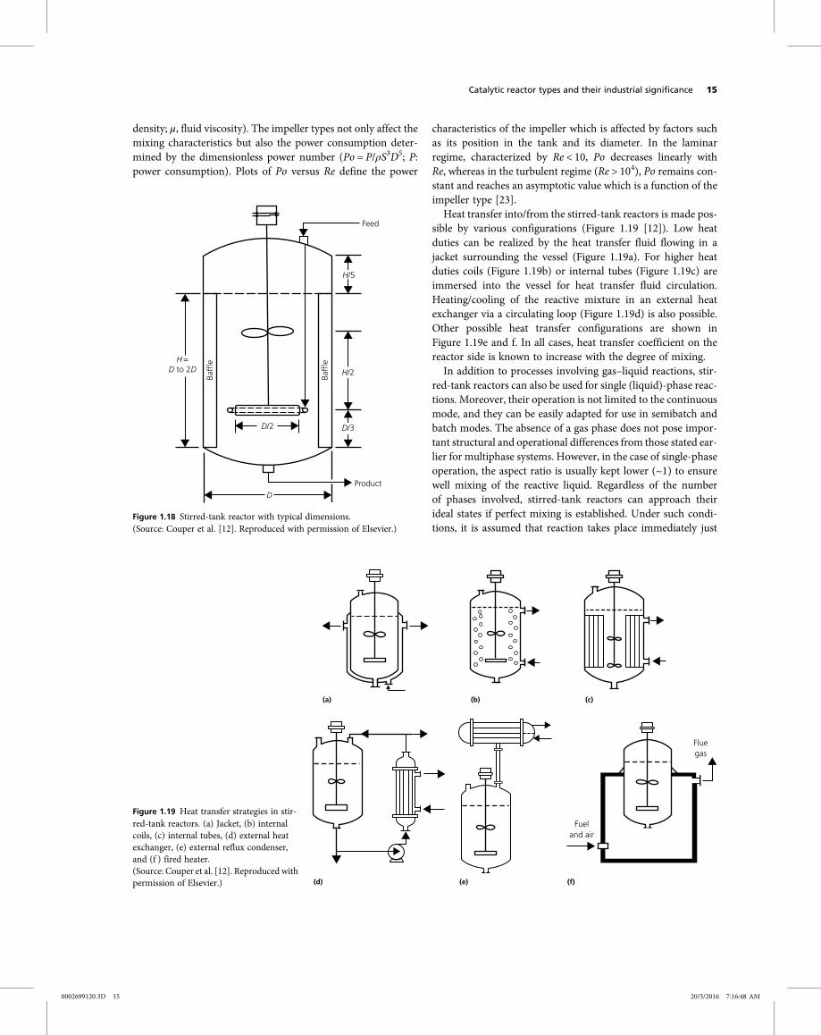
density; μ, fluid viscosity). The impeller types not only affect themixing characteristics but also the power consumption deter-mined by the dimensionless power number (Po = P/ρS3D5; P:power consumption). Plots of Po versus Re define the power
characteristics of the impeller which is affected by factors suchas its position in the tank and its diameter. In the laminarregime, characterized by Re < 10, Po decreases linearly withRe, whereas in the turbulent regime (Re > 104), Po remains con-stant and reaches an asymptotic value which is a function of theimpeller type [23].
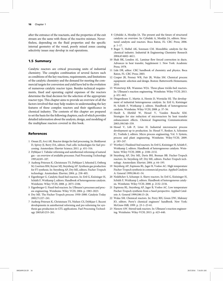
Heat transfer into/from the stirred-tank reactors is made pos-sible by various configurations (Figure 1.19 [12]). Low heatduties can be realized by the heat transfer fluid flowing in ajacket surrounding the vessel (Figure 1.19a). For higher heatduties coils (Figure 1.19b) or internal tubes (Figure 1.19c) areimmersed into the vessel for heat transfer fluid circulation.Heating/cooling of the reactive mixture in an external heatexchanger via a circulating loop (Figure 1.19d) is also possible.Other possible heat transfer configurations are shown inFigure 1.19e and f. In all cases, heat transfer coefficient on thereactor side is known to increase with the degree of mixing.
In addition to processes involving gas–liquid reactions, stir-red-tank reactors can also be used for single (liquid)-phase reac-tions. Moreover, their operation is not limited to the continuousmode, and they can be easily adapted for use in semibatch andbatch modes. The absence of a gas phase does not pose impor-tant structural and operational differences from those stated ear-lier for multiphase systems. However, in the case of single-phaseoperation, the aspect ratio is usually kept lower (~1) to ensurewell mixing of the reactive liquid. Regardless of the numberof phases involved, stirred-tank reactors can approach theirideal states if perfect mixing is established. Under such condi-tions, it is assumed that reaction takes place immediately just
(a)
(d) (e)
Fluegas
Fueland air
(f)
(b) (c)
Figure 1.19 Heat transfer strategies in stir-red-tank reactors. (a) Jacket, (b) internalcoils, (c) internal tubes, (d) external heatexchanger, (e) external reflux condenser,and (f ) fired heater.(Source: Couper et al. [12]. Reproduced withpermission of Elsevier.)
Feed
H/5
H/2
D/3D/2
Product
H=D to 2D
D
Baffl
e
Baffl
e
Figure 1.18 Stirred-tank reactor with typical dimensions.(Source: Couper et al. [12]. Reproduced with permission of Elsevier.)
Catalytic reactor types and their industrial significance 15
0002699120.3D 15 20/5/2016 7:16:48 AM
after the entrance of the reactants, and the properties of the exitstream are the same with those of the reactive mixture. Never-theless, depending on the fluid properties and the specificinternal geometry of the vessel, poorly mixed zones causingselectivity issues may develop in real operations.
1.5 Summary
Catalytic reactors are critical processing units of industrialchemistry. The complex combination of several factors suchas conditions of the key reactions, requirements, and limitationsof the catalytic chemistry and the demand for meeting the com-mercial targets for conversion and yield have led to the evolutionof numerous catalytic reactor types. Besides technical require-ments, fixed and operating capital expenses of the reactorsdetermine the final decision for the selection of the appropriatereactor type. This chapter aims to provide an overview of all thefactors involved that may help readers in understanding the keyfeatures of these complex reactors and their significance inchemical industry. The contents of this chapter are preparedto set the basis for the following chapters, each of which providesdetailed information about the analysis, design, and modeling ofthe multiphase reactors covered in this book.
References
1 Onsan ZI, Avci AK. Reactor design for fuel processing. In: ShekhawatD, Spivey JJ, Berry DA, editors. Fuel cells: technologies for fuel pro-cessing. Amsterdam: Elsevier Science; 2011. p. 451–516.
2 Dybkjaer I. Tubular reforming and autothermal reforming of naturalgas – an overview of available processes. Fuel Processing Technology1995;42:85–107.
3 Aasberg-Petersen K, Christensen TS, Dybkjaer I, Sehested J, OstbergM, Coertzen RM, Keyser MJ, Steynberg AP. Synthesis gas productionfor FT synthesis. In: Steynberg AP, Dry ME, editors. Fischer-Tropschtechnology. Amsterdam: Elsevier; 2004. p. 258–405.
4 Eigenberger G. Catalytic fixed-bed reactors. In: Ertl G, Knözinger H,Schüth F, Weitkamp J, editors. Handbook of heterogeneous catalysis.Weinheim: Wiley-VCH; 2008. p. 2075–2106.
5 Eigenberger G. Fixed-bed reactors. In: Ullmann’s processes and proc-ess engineering. Weinheim: Wiley VCH; 2004. p. 1983–2023.
6 Dry ME. The Fischer-Tropsch process: 1950–2000. Catalysis Today2002;71:227–241.
7 Aasberg-Petersen K, Christensen TS, Nielsen CS, Dybkjaer I. Recentdevelopments in autothermal reforming and pre-reforming for syn-thesis gas production in GTL applications. Fuel Processing Technol-ogy 2003;83:253–261.
8 Cybulski A, Moulijn JA. The present and the future of structuredcatalysts: an overview. In: Cybulski A, Moulijn JA, editors. Struc-tured catalysts and reactors. Boca Raton, FL: CRC Press; 2006.p. 1–17.
9 Boger T, Heibel AK, Sorensen CM. Monolithic catalysts for thechemical industry. Industrial & Engineering Chemistry Research2004;43:4602–4611.
10 Shah RK, London AL. Laminar flow forced convection in ducts.Advances in heat transfer, Supplement 1. New York: AcademicPress; 1978.
11 Lide DR, editor. CRC handbook of chemistry and physics. BocaRaton, FL: CRC Press; 2003.
12 Couper JR, Penney WR, Fair JR, Walas SM. Chemical processequipment: selection and design. Boston: Butterworth-Heinemann;2010.
13 Westerterp KR, Wammes WJA. Three-phase trickle-bed reactors.In: Ullmann’s reaction engineering. Weinheim: Wiley-VCH; 2013.p. 651–663.
14 Dingerdissen U, Martin A, Herein D, Wernicke HJ. The develop-ment of industrial heterogeneous catalysis. In: Ertl G, KnözingerH, Schüth F, Weitkamp J, editors. Handbook of heterogeneouscatalysis. Weinheim: Wiley-VCH; 2008. p. 37–56.
15 Hardt S, Ehrfeld W, Hessel V, Vanden Bussche KM.Strategies for size reduction of microreactors by heat transferenhancement effects. Chemical Engineering Communications2003;190:540–559.
16 Hessel V, Löb P, Löwe H. Industrial microreactor processdevelopment up to production. In: Hessel V, Renken A, SchoutenJC, Yoshida J, editors. Micro process engineering, Vol. 3: System,process and plant engineering. Weinheim: Wiley-VCH; 2009.p. 183–247.
17 Werther J. Fluidized-bed reactors. In: Ertl G, Knözinger H, Schüth F,Weitkamp J, editors. Handbook of heterogeneous catalysis. Wein-heim: Wiley-VCH; 2008. p. 2106–2132.
18 Steynberg AP, Dry ME, Davis BH, Breman BB. Fischer-Tropschreactors. In: Steynberg AP, Dry ME, editors. Fischer-Tropsch tech-nology. Amsterdam: Elsevier; 2004. p. 64–195.
19 Steynberg AP, Espinoza RL, Jager B, Vosloo AC. High temperatureFischer-Tropsch synthesis in commercial practice. Applied CatalysisA: General 1999;186:41–54.
20 Nedeltchev S, Schumpe A. Slurry reactors. In: Ertl G, Knözinger H,Schüth F, Weitkamp J, editors. Handbook of heterogeneous cataly-sis. Weinheim: Wiley-VCH; 2008. p. 2132–2156.
21 Espinoza RL, Steynberg AP, Jager B, Vosloo AC. Low temperatureFischer-Tropsch synthesis from a Sasol perspective. Applied Catal-ysis A: General 1999;186:13–26.
22 Walas SM. Chemical reactors. In: Perry RH, Green DW, MaloneyJO, editors. Perry’s chemical engineers’ handbook. New York:McGraw-Hill; 1999. p. 23-1–23-61.
23 Nienow AW. Stirred tank reactors. In: Ullmann’s reaction engineer-ing. Weinheim: Wiley-VCH; 2013. p. 623–640.
16 Chapter 1
0002699120.3D 16 20/5/2016 7:16:50 AM