Embed Size (px)
Citation preview

Visit the ShortCourses bookstore for original high-qualitybooks on digital photography.
Click the book cover
A Short Course inDigital Photography
Chapter 2The Foundations of
Digital Imaging
INTRODUCTION - PIXELS—ALL OUTPUT IS DOTS -
RESOLUTION OF DIGITAL DEVICES - CONVERTING UNITS
OF MEASUREMENT - COLOR DEPTH - IMAGE SENSORS -
IMAGE SENSORS AND COLORS - AREA ARRAY AND LINEAR
SENSORS - CCD AND CMOS IMAGE SENSORS -COMPRESSION - WEB SITES YOU MIGHT WANT TO VISIT
Chapter 02. The Foundations of Digital Imaging
http://www.shortcourses.com/chapter02.htm (1 of 21) [5/24/1999 2:29:42 PM]

INTRODUCTIONBefore we get into digital cameras and how they are used, let's take a look at some of the principles such asimage sensors, resolution, and color, that underlie the field of digital photography.
Unlike traditional cameras that use film to store an image, digital cameras use a solid-state device called animage sensor. These fingernail-sized silicon chips contain hundreds of thousands or millions ofphotosensitive diodes called photosites. Each of these photosites records the intensity or brightness of thelight that falls on it. Each photosite reacts to the light that falls on it by accumulating a charge; the morelight, the higher the charge. The brightness recorded by each photosite is then stored as a set of numbersthat can then be used to set the color and brightness of dots on the screen or ink on the printed page toreconstruct the image. In this chapter, we’ll look closely at this process because it’s the foundation ofeverything that follows.
Preconceptions of what a camera should be and what should be inside onehave been turned on their head. Welcome to the new world of digitalphotography. Courtesy of Intel.
PIXELS—ALL OUTPUT IS DOTSTurn on your computer and read your e-mail or write a paper. When you need to do some research, jumponto the Internet and browse historic video clips, art museums, and photography exhibits. When you’re inneed of a break, load a flight simulator program and fly through a photo-realistic computer world, or put on3D glasses and watch as things hurtle out of the screen at you. As different as these experiences may be,they all share one thing in common—you’re looking at nothing but dots. Like the impressionist painterswho painted wonderful scenes with small dots of paint, your screen, and your printer create images withsmall dots called picture elements—or just pixels.
Pixels are created by dividing an image into a grid. The computer can change the brightness of everysquare or pixel in this grid. By doing so, text and images are displayed. Controlling, or addressing a grid ofindividual pixels in this way is called bit mapping.
Chapter 02. The Foundations of Digital Imaging
http://www.shortcourses.com/chapter02.htm (2 of 21) [5/24/1999 2:29:43 PM]

Here you see a reproduction of the famous painting "The Spirit of ‘76" done injellybeans. Think of each jellybean as a pixel and it's easy to see how dots canform images. Jelly Bean Spirit of ’76 courtesy of Herman Goelitz Inc. Makersof Jelly Belly jelly beans.
If you enlarge any digital image enough, the pixels will begin to show—a process called pixelization. Thisis akin to silver-based prints where grain begins to show when prints are enlarged past a certain point.
A black-crowned night heron and a baby great blue heron stand on a loglooking like Mutt and Jeff or Bert and Ernie. Even when you click the image toenlarge it, the pixels don't show.
When a section is cropped from the large image and then enlarged, the squarepixels begin to show clearly. Click the image to see them even more clearly andnote how each pixel is a small square made up of a single color.
The makeup of a pixel varies depending on whether it's in the camera, on the screen, or on a printout.
In the camera, each photosite on the image sensor represents one pixel. The color of each pixelis calculated using the pixels surrounding it. This drawing shows nine pixels.
On the screen, each pixel is a single color formed by mixing the red, green, and blue light beamsor LCDs. This drawing shows nine pixels.
Chapter 02. The Foundations of Digital Imaging
http://www.shortcourses.com/chapter02.htm (3 of 21) [5/24/1999 2:29:43 PM]

On a printout, a pixel is formed from lots of much smaller dots that blend together to give theimpression of a single color. This drawing shows one pixel.
RESOLUTION OF DIGITAL DEVICESThe quality of any digital image, whether printed or displayed on a screen, depends in part on itsresolution—the number of pixels used to create the image. More and smaller pixels add detail and sharpenedges. This table lists some standards of comparison. The numbers from various sources differ. One greatthing about the Web is that you can talk back to an author and correct him. Click here to send a messagesetting me straight.
There are three ways to express the resolution of an image; by its dimensions in pixels, by the total numberof pixels, or by the pixels per inch (ppi) or dots per inch (dpi).
Element Resolution Total PixelsColor TV (NTSC) 320 x 525 168,000
Human eye 11,000 x 11,000 120 million
35-mm slide
The "Economist" magazine says it has 20 million or more. CMOSImaging News says 5 to 10 million depending on the film. Anothersource says about 80 million pixels. Robert Caspe at SoundVisionstates that color negative film has 1000 pixels per inch while colorpositive film has 2000 pixels per inch.
1982 Kodak Disccamera film 3 million pixels—each about 0.0003 inch in diameter
Resolution—Optical and Interpolated
Beware of claims about resolution for cameras and scanners because there are two kinds; optical andinterpolated. The optical resolution of a camera or scanner is an absolute number because an imagesensor's photosites are physical devices that can be counted. To improve resolution in certain limitedrespects, the resolution can be increased using software. This process, called interpolated resolution,adds pixels to the image. To do so, software evaluates those pixels surrounding each new pixel todetermine what its colors should be. For example, if all of the pixels around a newly inserted pixel arered, the new pixel will be made red. What's important to keep in mind is that interpolated resolutiondoesn't add any new information to the image—it just adds pixels and makes the file larger. This samething can be done in a photo editing program such as Photoshop by resizing the image. Beware ofcompanies that promote or emphasize their device's interpolated (or enhanced) resolution. You'regetting less than you think you are. Always check for the device's optical resolution. If this isn'tprovided, flee the product—you're dealing with marketing people who don't have your best interests atheart.
Camera Resolutions
As you have seen, image sensors contain a grid of photosites—each representing one pixel in the finalimage. The sensor's resolution is determined by how many photosites there are on its surface. This
Chapter 02. The Foundations of Digital Imaging
http://www.shortcourses.com/chapter02.htm (4 of 21) [5/24/1999 2:29:43 PM]

resolution is usually specified in one of two ways—by the sensor's dimension in pixels or by its totalnumber of pixels. For example, the same camera may specify its resolution as 1200 x 800 pixels (where "x"is pronounced "by" as in "1200 by 800"), or 960-thousand pixels (1200 multiplied by 800). Very high endcameras often refer to file sizes instead of resolution. For example, someone may say a camera creates30-Megabyte files. This is just a form of shorthand.
Camera resolutions are given as dimensions (1200 x 800) or by totals(960,000).
Low-end cameras currently have resolutions around 640 x 480 pixels, although this number constantlyimproves. Better cameras, those with 1 million or more pixels are called megapixel cameras and thosewith over 2-million are called multi-megapixel cameras. Even the most expensive professional digitalcameras give you only about 6-million pixels. As you might expect, all other things being equal, costs risewith the camera's resolution.
Size isn't everything!
The higher a camera's resolution, the larger the image files that it creates. For this reason, somecameras allow you to specify more than one resolution when you take a picture. Although you arelikely to get better results with a higher resolution, it isn't always needed—especially when the imageis going to be displayed on the Web or printed very small. In these cases lower resolution images willsuffice and because they have smaller file sizes, you'll be able to squeeze more into the camera'smemory.
Although more photosites mean higher resolution, adding more isn't easy and creates other problems. Forexample:
It adds significantly more photosites to the chip so the chip must be larger and each photositesmaller. Larger chips with more photosites increase difficulties (and costs) of manufacturing.Smaller photosites must be more sensitive to capture the same amount of light.
●
More photosites create larger image files, creating storage problems.●
Monitor Resolutions
The resolution of a display monitor is almost always given as a pair of numbers that indicate the screen'swidth and height in pixels. For example, a monitor may be specified as being 640 x 480, 800 x 600, 1024 x768, and so on.
The first number in the pair is the number of pixels across the screen.●
The second number is the number of rows of pixels down the screen.●
Chapter 02. The Foundations of Digital Imaging
http://www.shortcourses.com/chapter02.htm (5 of 21) [5/24/1999 2:29:43 PM]

This is a 640 x 480 display. That means there are 640 pixels on each rowand there are 480 rows.
Images displayed on the monitor are very low-resolution. As you can see from the table below, the actualnumber of pixels per inch depends on both the resolution and the size of the monitor. Generally, imagesthat are to be displayed on the screen are converted to 72 pixels per inch (ppi), a resolution held over froman early era in Apple's history. (The red numbers in the table are the pixels per inch for each combinationof screen size and resolution.) As you can see from the table, this isn't an exact number for any resolutionon any screen, but it tends to be a good compromise. If an image is 800 pixels wide, the pixels per inch aredifferent on a 10-inch wide monitor that on a 20-inch. The same number of pixels have to be spread over alarger screen so the pixels per inch falls.
ResolutionMonitor Size
14 15 17 19 21
640 x 480 60 57 51 44 41
800 x 600 74 71 64 56 51
1024 x 768 95 91 82 71 65
Printer and Scanner Resolutions
Printer and scanner resolutions are usually specified by the number of dots per inch (dpi) that they print orscan. (Generally pixels per inch refer to the image and display screen and dots per inch refer to the printerand printed image. Sometimes I think terminology shifts like this are done just to confuse us. In this bookwe use them interchangably) For comparison purposes, monitors use an average of 72 ppi to display textand images, ink-jet printers range up to 1700 dpi or so, and commercial typesetting machines rangebetween 1,000 and 2,400 dpi.
CONVERTING UNITS OF MEASUREMENTWhen working with digital images, there are times when you need to convert among image dimensionsgiven in inches, pixels, or pixels per inch (sometimes expressed as dots per inch). Don't tune out here, it'sonly multiplication and division!
Converting dimensions in pixels to inches
As you've seen, images are described by their dimensions in pixels. However, printouts are described ininches or centimeters. What if you have a digital image and want to make a printout. To know how large animage will be when displayed or printed, you have to convert from pixels to inches (or cm). To do so, youdivide the image's dimension in pixels by the resolution of the device in pixels per inch (ppi). For example,
Chapter 02. The Foundations of Digital Imaging
http://www.shortcourses.com/chapter02.htm (6 of 21) [5/24/1999 2:29:43 PM]

to convert the dimensions for a 1500 x 1200 image being printed at 300 ppi you divide as follows:
Width: 1500 pixels ÷ 300 ppi = 5"Height: 1200 pixels ÷ 300 ppi = 4"
The result is a 5" x 4" print. However, if the output device prints 600 ppi, the result changes to a 2.5" x 2"print as follows:
Width: 1500 pixels ÷ 600 ppi = 2.5"Height: 1200 pixels ÷ 600 ppi = 2"
Converting dimensions in inches to pixels
Scanning is the flip side of printing. You usually scan images measured in inches to create files defined inpixels. For example, when scanning a snapshot, to know what size the digital image will be, you need toconvert from inches to pixels. To do so, you multiply the number of inches times the pixels per inch (ppi)of the device. For example, if you scan a 4" x 5" image at 300 ppi, you calculate the length of each side inpixels by multiplying its dimensions in inches by the number of pixels per inch as follows:
Width: 5" x 300 ppi = 1500 pixelsHeight: 4" x 300 ppi = 1200 pixels
To convert from inches to pixels you multiply a length in inches times thepixels per inch. Here one side is 5 inches and the other is 4. To calculate thelength of each side in pixels, you multiply those lengths by the number of dotsper inch, in this case 300.
Converting dimensions in pixels to pixels per inch
When you make printouts from images, pixels begin to show when the print is enlarged to a point wherethe pixels per inch (ppi) fall too low. If your printer can print a sharp image only at 300 or more pixels perinch, you need to determine if the size of the image you plan on printing will fall below this level. Let's sayyou have a scanned image and want to print it at a certain size. When you enlarge or reduce an image likethis, the ppi change. To find out what the pixels (or dots) per inch becomes, you convert from the image'soriginal size in pixels to its pixels per inch. For example, if you scan a slide at 2700 ppi, your scannedimage is about 3712 pixels wide (a slide is about 1.375" wide). If you then print that scanned image so it's10" wide, the pixels are stretched over a larger area so the ppi on the print falls from 2700 ppi to 371 ppi(3712 pixels ÷ 10 inches = 371 pixels per inch). Also, if you know the size of the image in pixels, you candivide that number by the number of pixels you want to print per inch to determine the largest possibleprint size.
Here a slide is scanned at 2700 dpi. The resulting 3712 pixels are thenspread across a 10-inch wide print. The dpi on the print are 371. Click toenlarge the image.
Chapter 02. The Foundations of Digital Imaging
http://www.shortcourses.com/chapter02.htm (7 of 21) [5/24/1999 2:29:43 PM]
Resolution and Image Size
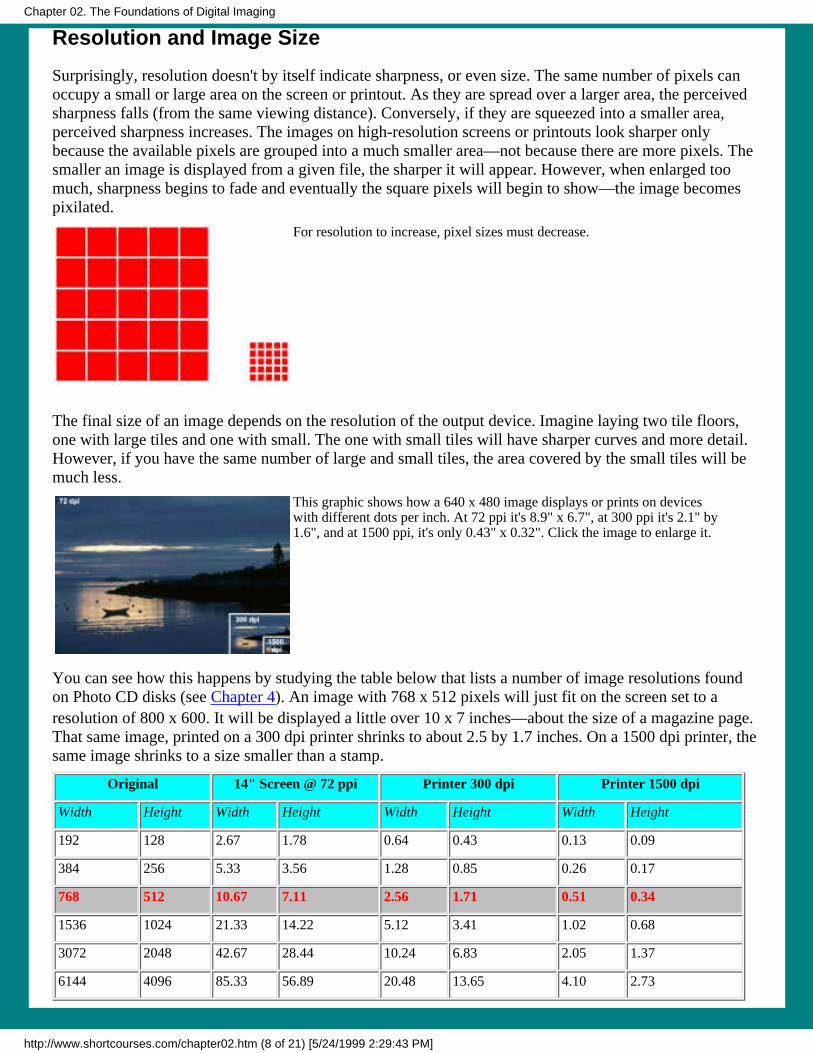
Surprisingly, resolution doesn't by itself indicate sharpness, or even size. The same number of pixels canoccupy a small or large area on the screen or printout. As they are spread over a larger area, the perceivedsharpness falls (from the same viewing distance). Conversely, if they are squeezed into a smaller area,perceived sharpness increases. The images on high-resolution screens or printouts look sharper onlybecause the available pixels are grouped into a much smaller area—not because there are more pixels. Thesmaller an image is displayed from a given file, the sharper it will appear. However, when enlarged toomuch, sharpness begins to fade and eventually the square pixels will begin to show—the image becomespixilated.
For resolution to increase, pixel sizes must decrease.
The final size of an image depends on the resolution of the output device. Imagine laying two tile floors,one with large tiles and one with small. The one with small tiles will have sharper curves and more detail.However, if you have the same number of large and small tiles, the area covered by the small tiles will bemuch less.
This graphic shows how a 640 x 480 image displays or prints on deviceswith different dots per inch. At 72 ppi it's 8.9" x 6.7", at 300 ppi it's 2.1" by1.6", and at 1500 ppi, it's only 0.43" x 0.32". Click the image to enlarge it.
You can see how this happens by studying the table below that lists a number of image resolutions foundon Photo CD disks (see Chapter 4). An image with 768 x 512 pixels will just fit on the screen set to aresolution of 800 x 600. It will be displayed a little over 10 x 7 inches—about the size of a magazine page.That same image, printed on a 300 dpi printer shrinks to about 2.5 by 1.7 inches. On a 1500 dpi printer, thesame image shrinks to a size smaller than a stamp.
Original 14" Screen @ 72 ppi Printer 300 dpi Printer 1500 dpi
Width Height Width Height Width Height Width Height
192 128 2.67 1.78 0.64 0.43 0.13 0.09
384 256 5.33 3.56 1.28 0.85 0.26 0.17
768 512 10.67 7.11 2.56 1.71 0.51 0.34
1536 1024 21.33 14.22 5.12 3.41 1.02 0.68
3072 2048 42.67 28.44 10.24 6.83 2.05 1.37
6144 4096 85.33 56.89 20.48 13.65 4.10 2.73
Chapter 02. The Foundations of Digital Imaging
http://www.shortcourses.com/chapter02.htm (8 of 21) [5/24/1999 2:29:43 PM]

To make an image larger or smaller for a given output device, it must be resized in a photo-editing programor by the application you're printing it with. Resizing is done by interpolation. When made larger, extrapixels are added and the color of each new pixel is determined by the colors of its neighbors. When madesmaller, some pixels are deleted.
When enlarged past a certain point, digital images become pixilated, loosing detail and showing the pixelsthey are made up from. One rule of thumb is that a 1.5 megapixel image can be enlarged to about 8 x 10before it starts showing pixels at a normal viewing distance. Kodak says that a 1-megapixel image can bereproduced photorealistically at 5" x 7". There is more on this subject in Chapter 4 in the section ScanningBlack Magic.
COLOR DEPTHResolution isn't the only factor governing the quality of your images. Equally important is color. When youview a natural scene, or a well done photographic color print, you are able to differentiate millions of colors. Digital images can approximate this color realism, but whether they do so on your system dependson its capabilities and its settings. How many colors there are in an image or how many a system candisplay is referred to as color depth, pixel-depth, or bit depth. Older PCs are stuck with displays thatshow only 16 or 256 colors. However, many newer systems include a video card and a monitor that candisplay what's called 24-bit True Color. It's called true color because these systems display 16 millioncolors, about the number the human eye can discern.
TIP: Checking Your System
You may have to set your system to full-color, it doesn't happen automatically. To see if yourWindows 95 system supports True Color, display Window's Start menu, click Settings, and then clickControl Panel. Double-click the Display icon to open the Display properties dialog box. Click theSettings tab on the dialog box and check the Color palette setting.
How do bits and colors relate to one another? It's simple arithmetic. To calculate how many different colorscan be captured or displayed, simply raise the number 2 to the power of the number of bits used to recordor display the image. For example, 8-bits gives you 256 colors because 28=256. Here's a table to show yousome other possibilities.
Name Bits per pixel Formula Number of colors
Black and white 1 21 2
Windows display 4 24 16
Gray scale 8 28 256
256 color 8 28 256
High color 16 216 65 thousand
True color 24 224 16 million
Some cameras and scanners will use 30 or more bits per pixel. These extra bits are used to improve thecolor in the image as it is processed down to its 24-bit final form.
Chapter 02. The Foundations of Digital Imaging
http://www.shortcourses.com/chapter02.htm (9 of 21) [5/24/1999 2:29:43 PM]

Black and white images require only2-bits to indicate which pixels arewhite and which are black.
Gray scale images need 8 bits todisplay 256 different shades of gray.
Color images are displayed using 4bits (16 colors), 8 bits (256 colors),16 bits (65 thousand colors) calledhigh color, and 24 bits (16 millioncolors) called true color.
Review: Bits and Bytes
When reading about digital systems, you frequently encounter the terms bit and byte.
The bit is the smallest digital unit. It's basically a single element in thecomputer that like a light bulb has only two possible states, on (indicating 1) oroff (indicating 0). The term bit is a contraction of the more descriptive phrasebinary digit.
Bytes are groups of 8-bits linked together for processing. Since each of theeight bits has two states (on or off), the total amount of information that can be
conveyed is 28 (2 raised to the 8th power), or 256 possible combinations.
Color depth is important at both ends of the spectrum. It's smart to match an image's color depth to theplanned use. For example, if an image is to be printed, 24-bit color is a must if you want colors to be brightand sharp. However, if an image is to be posted on the Web, most people are still using 256 color displays.Posting images with millions of colors will take them longer to download because the files are larger.
IMAGE SENSORSJust as in a traditional camera, light enters a digital camera through a lens controlled by a shutter. Digitalcameras have one of three types of electronic shutters that control the exposure:
Electronically shuttered sensors use the image sensor itself to set the exposure time. A timingcircuit tells it when to start and stop the exposure
●
Electromechanical shutters are mechanical devices that are controlled electronically.●
Electro-optical shutters are electronically driven devices in front of the image sensor which changethe optical path transmittance.
●
Chapter 02. The Foundations of Digital Imaging
http://www.shortcourses.com/chapter02.htm (10 of 21) [5/24/1999 2:29:43 PM]

From Light Beams to Images
When the shutter opens, rather than exposing film, the digital camera collects light on an image sensor—asolid state electronic device. As you've seen, the image sensor contains a grid of tiny photosites. As the lensfocuses the scene on the sensor, some photosites record highlights, some shadows, and others record all ofthe levels of brightness in between.
Image sensors are often tiny devices. The three most common sizes used in digitalstill cameras are just a fraction of the size of a 35mm slide or negative. Click toenlarge the image.
Each site converts the light falling on it into an electrical charge. The brighter the light, the higher thecharge. When the shutter closes and the exposure is complete, the sensor "remembers" the pattern itrecorded. The various levels of charge are then converted to digital numbers that can be used to recreate theimage.
Image sensors contain a grid of photosites that convert light shining on them to electricalcharges. These charges can then be measured and converted into digital numbers that indicatehow much light hit each site. Courtesy of VISION.
These two illustrations show how image sensors capture images.
Chapter 02. The Foundations of Digital Imaging
http://www.shortcourses.com/chapter02.htm (11 of 21) [5/24/1999 2:29:43 PM]
When an image is focused through the camera(or scanner) lens, it falls on the image sensor.Varying amounts of light hit each photosite andknock loose electrons that are then captured andstored. The number of electrons knocked loosefrom any photosite is directly proportional tothe amount of light hitting it.
When the exposure is completed, the sensor is like a checkerboard, withdifferent numbers of checkers (electrons) piled on each square (photosite).When the image is read off the sensor, the stored electrons are convertedto a series of analog charges which are then converted to digital values byan Analog-to-Digital (A to D) converter.
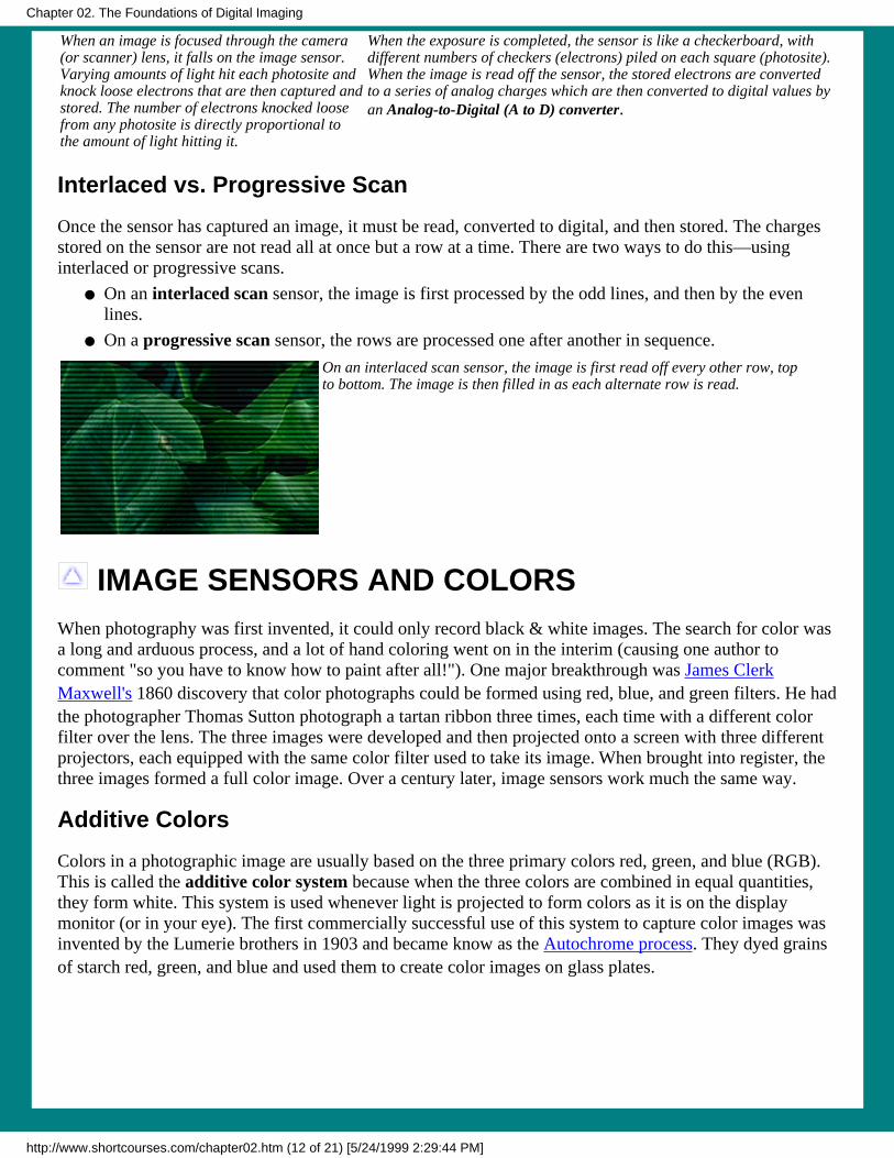
Interlaced vs. Progressive Scan
Once the sensor has captured an image, it must be read, converted to digital, and then stored. The chargesstored on the sensor are not read all at once but a row at a time. There are two ways to do this—usinginterlaced or progressive scans.
On an interlaced scan sensor, the image is first processed by the odd lines, and then by the evenlines.
●
On a progressive scan sensor, the rows are processed one after another in sequence.●
On an interlaced scan sensor, the image is first read off every other row, topto bottom. The image is then filled in as each alternate row is read.
IMAGE SENSORS AND COLORSWhen photography was first invented, it could only record black & white images. The search for color wasa long and arduous process, and a lot of hand coloring went on in the interim (causing one author tocomment "so you have to know how to paint after all!"). One major breakthrough was James ClerkMaxwell's 1860 discovery that color photographs could be formed using red, blue, and green filters. He hadthe photographer Thomas Sutton photograph a tartan ribbon three times, each time with a different colorfilter over the lens. The three images were developed and then projected onto a screen with three differentprojectors, each equipped with the same color filter used to take its image. When brought into register, thethree images formed a full color image. Over a century later, image sensors work much the same way.
Additive Colors
Colors in a photographic image are usually based on the three primary colors red, green, and blue (RGB).This is called the additive color system because when the three colors are combined in equal quantities,they form white. This system is used whenever light is projected to form colors as it is on the displaymonitor (or in your eye). The first commercially successful use of this system to capture color images wasinvented by the Lumerie brothers in 1903 and became know as the Autochrome process. They dyed grainsof starch red, green, and blue and used them to create color images on glass plates.
Chapter 02. The Foundations of Digital Imaging
http://www.shortcourses.com/chapter02.htm (12 of 21) [5/24/1999 2:29:44 PM]

RGB uses additive colors. When all three are mixed in equal amountsthey form white. When red and green overlap they form yellow, and soon.
Subtractive Colors
Although most cameras use the additive RGB color system, a few high-end cameras and all printers use theCMYK system. This system, called subtractive colors, uses the three primary color Cyan, Magenta, andYellow (hence the CMY in the name—the K stands for an extra black). When these three colors arecombined in equal quantities, the result is a reflected black because all of the colors are subtracted. TheCMYK system is widely used in the printing industry, but if you plan on displaying CMYK images on thescreen, they have to be converted to RGB and you lose some color accuracy in the conversion.
When you combine cyan, magenta, and yellow inks or pigments, you createsubtractive colors. (This illustration is still rough and will stay that way to I canfigure out how to easily combine the colors in CorelDraw or give up and turn itover to a real computer artist. In the meantime, you might want to visit Olympusto see another illustration of the same thing.)
It's All Black and White After All
Image sensors record only the gray scale—a series of 256 increasingly darker tones ranging from purewhite to pure black. Basically, they only capture brightness.
The gray scale contains a range of tones from pure white to pure black. (Also seehttp://www.hsdesign.com/scanning/welcome.html).
How, then do sensors capture colors when all they can do is record grays? The trick is to use red, green,and blue filters to separate out the red, green and blue components of the light reflected by an object.(Likewise, the filters in a CMYK sensor will be either cyan, magenta, or yellow.) There are a number of
Chapter 02. The Foundations of Digital Imaging
http://www.shortcourses.com/chapter02.htm (13 of 21) [5/24/1999 2:29:44 PM]
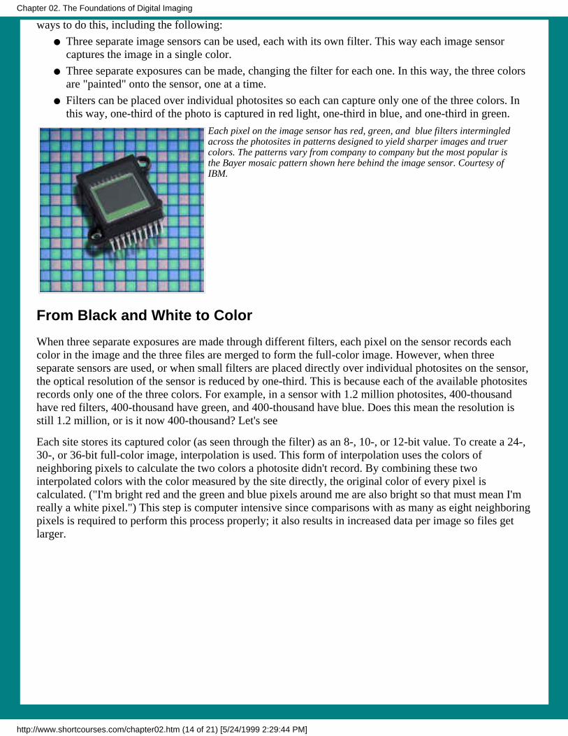
ways to do this, including the following:
Three separate image sensors can be used, each with its own filter. This way each image sensorcaptures the image in a single color.
●
Three separate exposures can be made, changing the filter for each one. In this way, the three colorsare "painted" onto the sensor, one at a time.
●
Filters can be placed over individual photosites so each can capture only one of the three colors. Inthis way, one-third of the photo is captured in red light, one-third in blue, and one-third in green.
●
Each pixel on the image sensor has red, green, and blue filters intermingledacross the photosites in patterns designed to yield sharper images and truercolors. The patterns vary from company to company but the most popular isthe Bayer mosaic pattern shown here behind the image sensor. Courtesy ofIBM.
From Black and White to Color
When three separate exposures are made through different filters, each pixel on the sensor records eachcolor in the image and the three files are merged to form the full-color image. However, when threeseparate sensors are used, or when small filters are placed directly over individual photosites on the sensor,the optical resolution of the sensor is reduced by one-third. This is because each of the available photositesrecords only one of the three colors. For example, in a sensor with 1.2 million photosites, 400-thousandhave red filters, 400-thousand have green, and 400-thousand have blue. Does this mean the resolution isstill 1.2 million, or is it now 400-thousand? Let's see
Each site stores its captured color (as seen through the filter) as an 8-, 10-, or 12-bit value. To create a 24-,30-, or 36-bit full-color image, interpolation is used. This form of interpolation uses the colors ofneighboring pixels to calculate the two colors a photosite didn't record. By combining these twointerpolated colors with the color measured by the site directly, the original color of every pixel iscalculated. ("I'm bright red and the green and blue pixels around me are also bright so that must mean I'mreally a white pixel.") This step is computer intensive since comparisons with as many as eight neighboringpixels is required to perform this process properly; it also results in increased data per image so files getlarger.
Chapter 02. The Foundations of Digital Imaging
http://www.shortcourses.com/chapter02.htm (14 of 21) [5/24/1999 2:29:44 PM]

Here the full-color of the center red pixel is about to beinterpolated from the colors of the eight surroundingpixels.
Color Aliasing
When interpolation is used, there has to be enough information in surrounding pixels to contribute colorinformation. This isn't always the case. Low-resolution image sensors have a problem called color aliasingthat occurs when a spot of light in the original scene is only big enough to be read by one or two pixels.Surrounding pixels don't contain any accurate color information about the pixel so the color of that spotmay show up as a dot of color disconnected from the surrounding image. Another form of color aliasingshows up as out of place color fringes surrounding otherwise sharply defined objects.
Color Channels
Each of the colors in an image can be controlled independently and is called a color channel. If a channelof 8-bit color is used for each color in a pixel—red, green, and blue—the three channels can be combinedto give 24-bit color.
When an image is open in PhotoShop a dialog box shows the red, green,and blue channels so you can select the one you want to work on. The topimage in the dialog box is the combined 24-bit RGB.
AREA ARRAY AND LINEAR SENSORSHand a group of camera or scanner designers a theory and a box of components and you'll see fireworks.They will explore every possible combination to see which works best. The market determines the eventualwinners in this "throw them against the wall and see what sticks" approach. At the moment, designers havetwo types of components to play with: area array and linear sensors.
Chapter 02. The Foundations of Digital Imaging
http://www.shortcourses.com/chapter02.htm (15 of 21) [5/24/1999 2:29:44 PM]

Area Array Sensors
Most cameras use area-array sensors with photosites arranged in a grid because they can cover the entireimage area and capture an entire image all at once.
Area array image sensors have their photosites (pixels) arranged in a grid so they can instantlycapture a full image. Courtesy of VISION.
These area array sensors can be incorporated into a camera in a variety of ways.
One-chip, one-shot cameras use different color filters over each photosite to capture all three colorswith a single exposure. This is the most common form of image sensor used in consumer-leveldigital cameras.
●
One chip, three shot cameras take three separate exposures: one each for red, green, and blue. Adifferent colored filter is placed in front of the image sensor for each of the colors. These camerascannot photograph moving objects in color (although they can in black & white) and are usually usedfor studio photography.
●
Two-chip cameras capture chromonance using one sensor (usually equipped with filters for redlight and blue light) and luminance with a second sensor (usually the one capturing green light).Two-chip cameras require less interpolation to render true colors.
●
Three-chip cameras, such as one from MegaVision, use three full frame image sensors; each coatedwith a filter to make it red-, green- or blue-sensitive. A beam splitter inside the camera dividesincoming images into three copies; one aimed at each of the sensors. This design delivershigh-resolution images with excellent color rendering. However, three-chip cameras tend to be bothcostly and bulky.
●
Linear Sensors
Scanners, and a few professional cameras, use image sensors with photosites arranged in either one row orthree called linear image sensors. Because they don't cover the entire image area, the image must bescanned across the sensor as it builds up the image from the captured rows of pixels. Cameras with thesesensors are useful only for motionless subjects and studio photography. However, these sensors are widelyused in scanners.
Chapter 02. The Foundations of Digital Imaging
http://www.shortcourses.com/chapter02.htm (16 of 21) [5/24/1999 2:29:44 PM]

As a linear sensor scans an image a line at a time itgradually builds up a full image.
Linear image sensors put a different color filter over the device for three separate exposures—oneeach to capture red, blue or green.
●
Tri-linear sensors use three rows of photosites—each with a red, green, or blue filter. Since eachpixel has it's own sensor, colors are captured very accurately in a single exposure.
●
CCD AND CMOS IMAGE SENSORSUntil recently, CCDs were the only image sensors used in digital cameras. They have been well developedthrough their use in astronomical telescopes, scanners, and video camcorders. However, there is a newchallenger on the horizon, the CMOS image sensor that promises to eventually become the image sensor ofchoice in a large segment of the market.
Image sensors are formed on silicon waffers and then cut apart. Courtesy ofIBM.
CCD Image Sensors
Charge-coupled devices (CCDs) capture light on the small photosites on their surface and get their namefrom the way that charge is read after an exposure. To begin, the charges on the first row are transferred toa read out register. From there, the signals are then fed to an amplifier and then on to an analog-to-digitalconverter. Once the row has been read, its charges on the read-out register row are deleted, the next rowenter the read-out register, and all of the rows above march down one row. The charges on each row are"coupled" to those on the row above so when one moves down, the next moves down to fill its old space. Inthis way, each row can be read—one row at a time.
Chapter 02. The Foundations of Digital Imaging
http://www.shortcourses.com/chapter02.htm (17 of 21) [5/24/1999 2:29:44 PM]

The CCD shifts one whole row at a time into the readout register. Thereadout register then shifts one pixel at a time to the output amplifier. Clickthe drawing to enlarge it.
It is technically feasible but not economic to use the CCD manufacturing process to integrate other camerafunctions, such as the clock drivers, timing logic, and signal processing on the same chip as the photosites.These are normally put on separate chips so CCD cameras contain several chips, often as many as 8, andnot fewer than 3.
History
The CCD was born for the wrong reasons actually. In the 1960s there were computers but theinexpensive mass-produced memory they needed to operate (and which we take for granted) did notyet exist. Instead, there were lots of strange and unusual ways being explored to store data while it wasbeing manipulated. One form actually used the phosphor coating on the screen of a display monitorand wrote data to the screen with one beam of light and read it back with another. However, at the timethe most commonly used technology was bubble memory At Bell Labs, where bubble memory wasinvented, they then came up with the CCD as a way to store data in 1969. Two Bell Labs scientists,Willard Boyle and George Smith, "started batting ideas around," in Smith's words, "and inventedcharge-coupled devices in an hour. Yes, it was unusual -- like a light bulb going on." Since then, thelight bulb has reached far and wide. Here are some highlights:
In 1974, the first imaging CCD was produced by Fairchild Electronics with a format of 100x100pixels.
●
In 1975,the first CCD TV cameras ready for use in commercial broadcasts.●
In 1975, the first CCD flatbed scanner was introduced by Kurzweil Computer Products using thefirst CCD integrated chip, a 500 sensor linear array from Fairchild.
●
In 1979, an RCA 320x512 Liquid Nitrogen cooled CCD system saw first light on a 1-metertelescope at Kitt Peak National Observatory. Early observations with this CCD quickly showedits superiority over photographic plates.
●
In 1982, the first solid state camera was introduced for video-laparoscopy (don't ask!)●
CMOS Image Sensors
Image sensors are manufactured in wafer foundries or fabs. Here the tiny circuits and devices are etchedonto silicon chips. The biggest problem with CCDs is that there isn't enough economy of scale. They arecreated in foundries using specialized and expensive processes that can only be used to make CCDs.Meanwhile, more and larger foundries across the street are using a different process calledComplementary Metal Oxide Semiconductor (CMOS) to make millions of chips for computerprocessors and memory. This is by far the most common and highest yielding process in the world. Thelatest CMOS processors, such as the Pentium II, contain almost 10 million active elements. Using this sameprocess and the same equipment to manufacturer CMOS image sensors cuts costs dramatically becausethe fixed costs of the plant are spread over a much larger number of devices. (CMOS refers to how asensor is manufactured, and not to a specific sensor technology.) As a result of this economy of scale, thecost of fabricating a CMOS wafer is one-third the cost of fabricating a similar wafer using a specializedCCD process.
Chapter 02. The Foundations of Digital Imaging
http://www.shortcourses.com/chapter02.htm (18 of 21) [5/24/1999 2:29:44 PM]

VISION's 800 x 1000 color sensor provides high resolution at lower costthan comparable CCDs. Image courtesy of VISION.
Passive- and Active-pixel sensors
There are two basic kinds of CMOS image sensors—passive and active.
Passive-pixel sensors (PPS) were the first image-sensor devices used in the 1960s. In passive-pixelCMOS sensors, a photosite converts photons into an electrical charge. This charge is then carried offthe sensor and amplified. These sensors are small—just large enough for the photosites and theirconnections. The problem with these sensors is noise that appears as a background pattern in theimage. To cancel out this noise, sensors often use additional processing steps.
●
Active-pixel sensors (APSs) reduce the noise associated with passive-pixel sensors. Circuitry ateach pixel determines what its noise level is and cancels it out. It is this active circuitry that gives theactive-pixel device its name. The performance of this technology is comparable to manycharge-coupled devices (CCDs) and also allows for a larger image array and higher resolution.
●
Inexpensive low-power passive-pixel CMOS chips are being used in low-end digital cameras. There is aconsensus that while these devices may dominate the low-end of the camera market, more expensiveactive-pixel sensors will become dominant in niches.
Toshiba Corporation fabricates a 1,300,000 pixel complementary metal oxidesemiconductor (CMOS) image sensor. Courtesy of Toshiba.
CMOS image sensor facts
Here are some things you might like to know about CMOS image sensors:
CMOS image quality is now matching CCD quality in the low- and mid-range, leaving only thehigh-end image sensors still unchallenged.
●
CMOS image sensors can incorporate other circuits on the same chip, eliminating the many separatechips required for a CCD. This also allows additional on-chip features to be added at little extra cost.These features include anti-jitter (image stabilization) and image compression. Not only does thismake the camera smaller, lighter, and cheaper; it also requires less power so batteries last longer.
●
CMOS image sensors can switch modes on the fly between still photography and video. However,video generates huge files so initially these cameras will have to be tethered to the mothership (thePC) when used in this mode for all but a few seconds of video. However, this mode works well forvideo conferencing although the cameras can't capture the 20 frames a second needed for full-motion
●
Chapter 02. The Foundations of Digital Imaging
http://www.shortcourses.com/chapter02.htm (19 of 21) [5/24/1999 2:29:44 PM]

video.
While CMOS sensors excel in the capture of outdoor pictures on sunny days, they suffer in low lightconditions. Their sensitivity to light is decreased because part of each photosite is covered withcircuitry that filters out noise and performs other functions. The percentage of a pixel devoted tocollecting light is called the pixel’s fill factor. CCDs have a 100% fill factor but CMOS camerashave much less. The lower the fill factor, the less sensitive the sensor is and the longer exposuretimes must be. Too low a fill factor makes indoor photography without a flash virtually impossible.To compensate for lower fill-factors, micro-lenses can be added to each pixel to gather light from theinsensitive portions of the pixel and "focus" it down to the photosite. In addition, the circuitry can bereduced so it doesn't cover as large an area.
Fill factor refers to the percentage of aphotosite that is sensitive to light. If circuitscover 25% of each photosite, the sensor issaid to have a fill factor of 75%. The higherthe fill factor, the more sensitive the sensor.
●
CMOS sensors have a higher noise level than CCDs so the processing time between pictures ishigher as these sensors use digital signal processing (DSP) to reduce or eliminate the noise. The DSPis one early camera (the Svmini), executes 600,000,000 instructions per picture.
●
COMPRESSIONWhen you take a photograph, the size of the image file is huge compared to many other types of computerfiles. For example, a low-resolution 640 x 480 image has 307,200 pixels. If each pixel uses 24 bits (3 bytes)for true color, a single image takes up about a megabyte of storage space. As the resolution increases, sodoes the file size. At a resolution of 1024 x 768, each 24-bit picture takes up 2.5 megabytes. To makeimage files smaller and more manageable, almost every digital camera uses some form of compression.Compressing images not only let's you save more images on the camera's storage device, it also allowsyou to download and display them more quickly.
How Compression Works
During compression, data that is duplicated or which has no value is eliminated or saved in a shorter form,greatly reducing a file’s size. When the image is then edited or displayed, the compression process isreversed.
There are two forms of compression—lossless and lossy—and digital photography uses both forms.
Lossless compression
Lossless compression (also called reversible compression) uncompresses an image so its quality matchesthe original source. Although lossless compression sounds ideal, it doesn’t provide much compression.Generally, compressed files are still a third the size of the original file, not small enough to make muchdifference in most situations. For this reason, lossless compression is used mainly where detail is extremelyimportant as in x-rays and satellite imagery. A leading lossless compression scheme is LZW(Lempel-Ziv-Welch). This is used in GIF and TIFF files and achieves compression ratios of 50 to 90%
Chapter 02. The Foundations of Digital Imaging
http://www.shortcourses.com/chapter02.htm (20 of 21) [5/24/1999 2:29:45 PM]

Lossy compression
Although it's possible to compress images without loosing some quality, it's not practical in many cases.Therefore, all popular digital cameras use a lossy compression (rhymes with bossy) that degrades imagesto some degree and the more they're compressed, the more degraded they become. In many situations, suchas posting images on the Web, the image degradation isn't obvious. However, enlarged prints show it off.
Although lossy compression does not uncompress images to the same quality as the original source, theimage remains visually lossless and appears normal. The trick is to remove data that isn’t obvious to theviewer. For example, if large areas of the sky are the same shade of blue, only the value for one pixel needsto be saved along with the locations of where the other identical pixels appear in the image. The leadinglossy compression scheme is JPEG (Joint Photographic Experts Group) used in JFIF files (JPEG FileInterchange Format). This scheme allows you to select the degree of compression. Compression Ratiosbetween 10:1 and 40:1 are common.
Because lossy compression affects the image, most cameras allow you to choose between different levelsof compression. This allows you to choose between lower compression and higher image quality or greatercompression and poorer quality. The only reason to choose higher compression is because it creates smallerfile size so you can store more images, send them by e-mail, or post them on the Web. Most cameras giveyou two or three choices equivalent to Good, Better, Best although the names change. (If there were truthin labeling they would be called worst, worse, and good.)
WEB SITES YOU MIGHT WANT TO VISITKodak's Digital Learning Center is a collection of information, tips and techniques on DigitalImaging. The site contains a number of "books."
The How To Book presents step-by-step instructions on using digital pictures.❍
The Technology Book explains digital imaging technology.❍
The Courses Book contains a variety of digital training courses.❍
The Reference Book provides tools to help you understand digital imaging.❍
The PhotoChat Book provides information about the weekly "Show-And-Tell" PhotoChatsand allows you to visit chats of the past.
❍
●
Canon's From the Darkroom to the Desktop provides an introduction to digital photography.●
Copyright 1998 Dennis P. Curtin. All rights reserved. Legal stuff.
Chapter 02. The Foundations of Digital Imaging
http://www.shortcourses.com/chapter02.htm (21 of 21) [5/24/1999 2:29:45 PM]