Embed Size (px)
Citation preview
Chapitre 4
Tour d’horizon des atomiseurs
Différents types d’atomiseurs (Bayvel & Orzechowski, 1993)
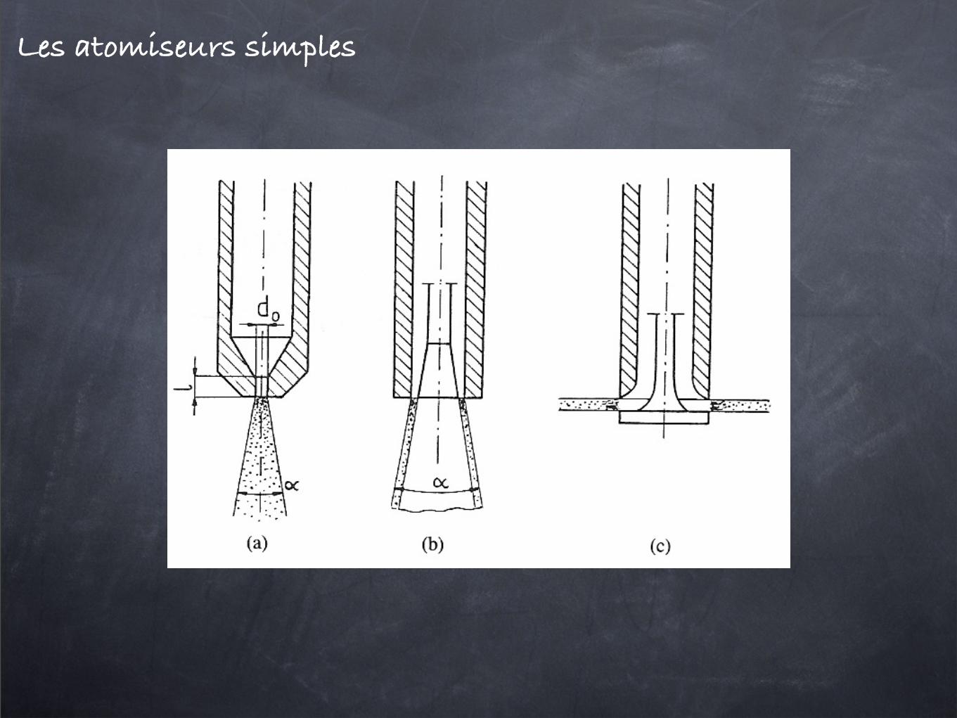
Les atomiseurs simples
Journal of Fluid Mechanics, Vol. 83, part 1 Plate 1
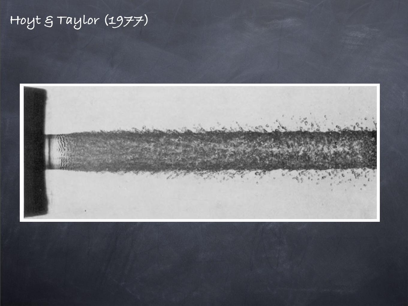
FIGURE 2. Je t emerging from 0.25 in. diameter nozzle into stagnant air. Je t velocity = 83 ft/s.
HOYT AND TAYLOR (B’accnq p . 118)
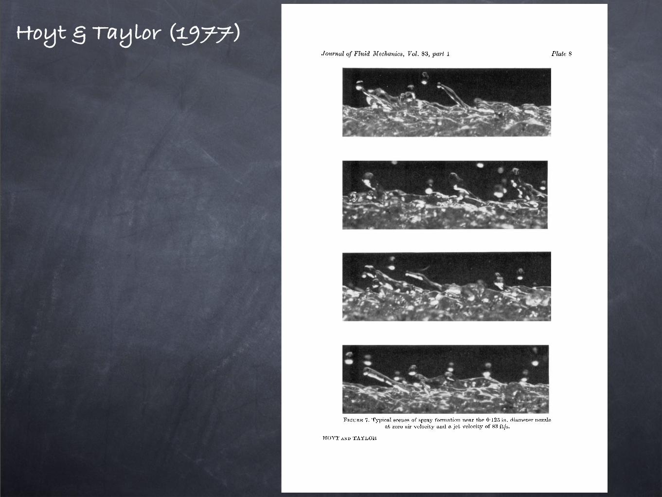
Hoyt & Taylor (1977)
Hoyt & Taylor (1977)Journul of Fluid Mechanics, VoE. 83, part 1
FIGURE 7 . Typical scenes of spray formation near the 0.125 in. diameter nozzle at zero air velocity and a jet velocity of 83 ft/s.
H O Y T AND TAYLOR
Plate 8
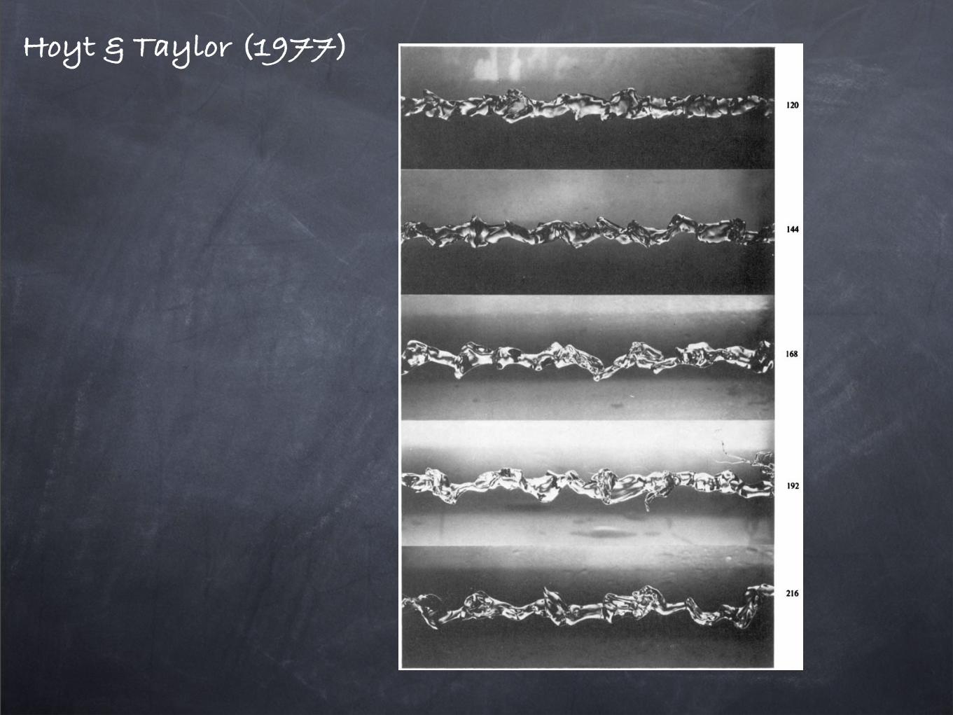
Hoyt & Taylor (1977)Journal of Fluid Mechanics, Vol. 83, part 1 Plate 11
1 20
144
168
192
216
( b )
FIGURE 9. Photos of jet from 0.25 in. diameter nozzle in stagnant air using 200 p.p.m. poly- (ethylene oxide) solution instead of plain water; photos were taken 24 nozzle diameters apart.
HOYT AND TAYLOR
Les atomiseurs groupés
Les atomiseurs à impact de jets
13
Chapitre 2
Nappe liquide formee parl’impact oblique de deux jets
(a) (b)
10 mm
ujuj
djdj
!
y
x
r
"
g
(c)
Fig. 2.1: (a) Schema d’une nappe formee par l’impact oblique de deux jetsidentiques. (b) Vue de face d’une nappe lisse obtenue avec de l’ethanol, 2! =90˚, dj = 1.05 mm et uj = 2.1 m/s. (c) Vue de face d’une nappe fragmenteeobtenue avec de l’eau 2! = 90˚, dj = 1.05 mm et uj = 4 m/s .
Ce chapitre presente l’etude d’une lame liquide formee par la collisionde deux jets identiques, figure 2.1-a. La physionomie de la nappe depend dela vitesse uj et du diametre dj des jets, de leur angle d’impact ! ainsi quedes proprietes du liquide, c’est-a-dire la masse volumique ", la tension desurface # et la viscosite cinematique $. Deux exemples de nappes obtenuesdans cette configuration sont presentes sur les figures 2.1-b et c pour deux
tel-00011518, vers
ion 1
- 1
Feb 2
006
Les atomiseurs à impact de jets
10 Introduction
N2O4 MMH, UDMH
(a) (b)
2!
Fig. 1.11: (a) Atomisation de reactifs hypergoliques par l’intermediaire denappes formees par la collision de deux jets. (b) Moteur realise par laSNECMA constitue d’injecteurs a impact, il s’agit ici d’un test avec del’eau.
Dans les moteurs fusee, les nappes liquides sont utilisees pour fragmen-ter des reactifs hypergoliques, c’est-a-dire qu’ils reagissent des leur miseen contact. Il n’y a pas besoin d’apporter d’energie initiale, comme c’estpar exemple le cas pour le kerosene. Le premier liquide est un oxydant, ils’agit generalement du peroxyde d’azote (N2O4), et le second de l’hydra-zine, monomethylhydrazine (MMH) ou bien unsymmetrical dimethylhydra-zine (UDMH). Ces liquides sont mis en contact sous forme de gouttes parl’intermediaire d’une nappe formee par la collision de deux jets, figure 1.11-a. La figure 1.11-b presente une serie de nappes issues d’injecteurs a impactconstituant le moteur des turbopompes servant a alimenter le premier etagede la fusee Arianne 4. Ce moteur a ete elabore par la SNECMA. Les in-jecteurs a impact sont installes sur les moteurs des satellites permettant lecontrole en hauteur et la correction de leur orbite.
tel-00011518, vers
ion 1
- 1
Feb 2
006
Les atomiseurs à impact de jets
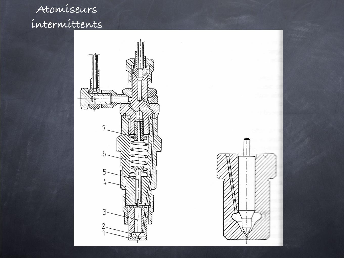
Atomiseurs intermittents
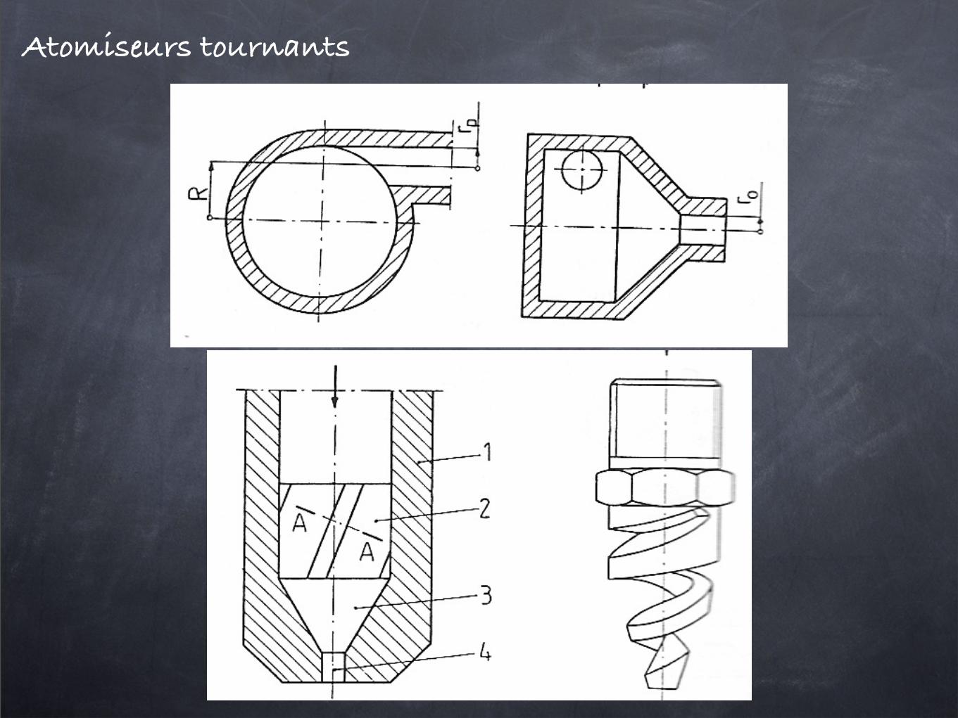
Atomiseurs tournants
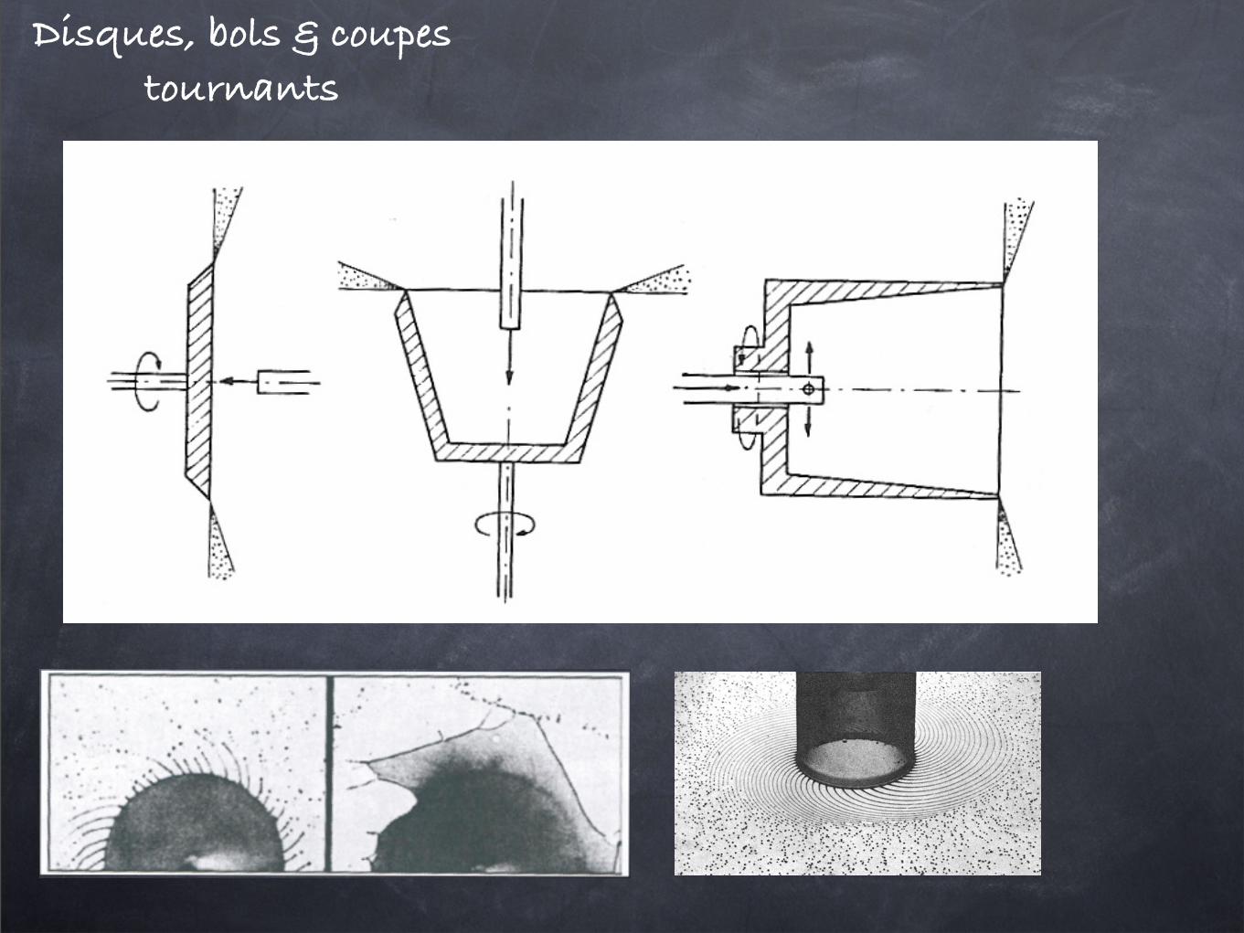
Disques, bols & coupes tournants
Rep. Prog. Phys. 71 (2008) 036601 J Eggers and E Villermaux
Figure 45. Formation of liquid threads from a rotating hollowtube [264].
liquid is deposited as a film on a rapidly rotating disc or hollowtube, and ejects liquid threads spaced by the above length scale2!/k! (see figure 45 and [264–266]). In another context, theprocess is known as ‘prilling’, and used to produce fertilizerand magnesium pellets [262, 263, 267].
3.11.2. Rotating jets. The study of jets in solid body rotationwas pioneered by Beer [15]. Here, the base flow (158) isreplaced by
v" = #r and vr = 0. (163)
This is produced very easily by rotating the entire nozzle fromwhich the jet is emerging [268], or by rotating one fluid insideanother, as already done by Plateau [269] (see also [261] andfigure 44). The latter is the geometry of the ‘spinning droptensiometer’ [270], which is used to measure very small valuesof the surface tension between two liquids. The result ofan axisymmetric stability analysis in the absence of an outerliquid [268, 271] is that angular rotation, as quantified by theparameter
L = $
%#h30
, (164)
always destabilizes the jet. In particular, the jet is unstable for
0 < kh0 <"
1 + L#1, (165)
independent of viscosity [272].The full axisymmetric stability analysis (again without
outer fluid), as well as experimental tests, was performedby [268]. The limiting case of an inviscid fluid [271] shows anincrease in the growth rate with the speed of rotation relativeto (57), and consistent with (165). The opposite case of verylarge viscosity leads to a simple extension of (80)
#i& = $
2h0'
1 # (kh0)2 + L#1
1 + (kh0)2[1 # (I0(kh0)/I1(kh0))2], (166)
which is of course once more consistent with (165). In arather extensive recent study [273], the transition towards non-axisymmetric ‘swirling’ modes was considered as well.
It is interesting to note that a naive long-wavelengthdescription of a rotating jet [274] is in general not consistentwith (165). The reason for this is the formation of a verythin boundary layer near the free surface of the jet for small&, i.e. near the stability boundary [275]. Namely, Rayleigh’s
stability criterion for a rotating fluid implies that the interior ofthe fluid be stabilized, while the Rayleigh–Taylor mechanismdestabilizes the free surface, squeezing disturbances to withina very thin layer. For very large viscosities, however, the long-wavelength description becomes consistent, and the analogueof (85) becomes
# i& = 16(v
[1 # (kh0)2 + L#1]. (167)
Finally, the two-fluid case, relevant to the measurement ofsurface tension, was investigated in the viscous limit in [276].In the spinning drop tensiometer the lighter fluid moves to thecentre, where it is stabilized by the rotation. The stability iscontrolled by the ‘rotational Bond number’ [276]
Bo# =(%2 # %1)#
2h30
$, (168)
which without an outer fluid (%1 = 0) is Bo# = #L#1. When0 < Bo# < 1, the thread is unstable in the wavenumber region0 < kh0 <
"1 # Bo#, while it becomes completely stable for
Bo# > 1. Thus as # is reduced, the liquid cylinder breaks up,and from a measurement of the growth rates the surface tensioncan be deduced [270, 276].
3.11.3. Jet in a cross flow. Consider a jet of radius h0 anddensity % issuing at velocity v0 into a gaseous environment(density %a) flowing at a translational velocity u perpendicularto the ejection direction of the jet (figure 46). The drag forceexerted by the velocity contrast bends the jet. A simple forcebalance on a length element d) of the jet between the air dragand the centrifugal inertia of the liquid reads
CD%au2h0 d) $ %h2
0v2
0
Rd), (169)
where R is the radius of curvature of the jet’s trajectory inthe fixed frame, and CD a drag coefficient of order unity. Thebalance can thus be simplified to
R
h0$ %
%a
!v0
u
"2. (170)
Now, the jet fluid is subjected to an acceleration g % v20/R
in the plane of the jet’s trajectory, so the outer surface of thejet suffers a Rayleigh–Taylor instability, whose wavelength iscontrolled by the capillary length * $
"$ /(% # %a)g. Thus
for % & %a one obtains
*
h0$ We#1/2 with We = %au
2h0
$. (171)
The wavelength (171) is independent of the liquid velocity andits density. This instability hinders the capillary instabilitywhen its time of growth
"*/g = ($ /%g3)1/4 is shorter than
the capillary time ( =#
%h30/$ , that is, as soon as
We = %au2h0
$> 1. (172)
33
L’influence déstabilisatrice de la rotation
L’influence déstabilisatrice de la rotation
Rep. Prog. Phys. 71 (2008) 036601 J Eggers and E Villermaux
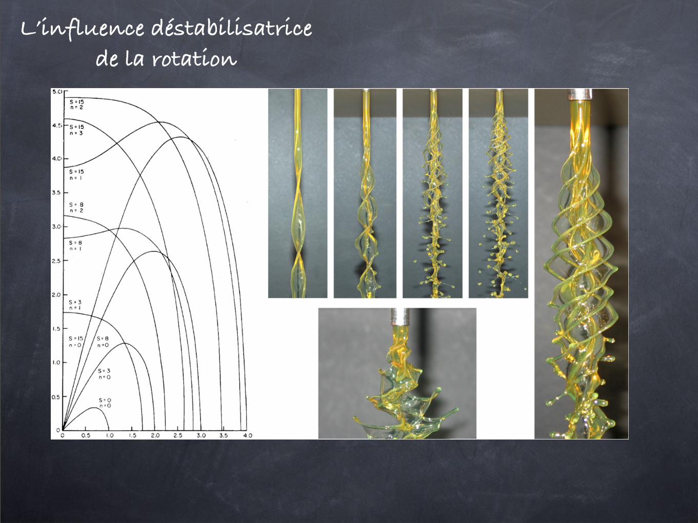
Figure 44. (Left) Dispersion curve of a swirling jet representing the growth rate (in units of!
! /"h30) versus dimensionless longitudinal
wavenumber kh0 for various azimuthal wavenumbers m. Adapted from Ponstein (1959) [260]. (Right) Still images of helical instabilities ona rotating jet, showing how the most amplified azimuthal wavenumber increases as the rotation increases, subsequent ligament and dropformation. Courtesy of Kubitschek and Weidman [261]. Reprinted with permission, copyright 2007 by the American Institute of Physics.
3.11.1. Swirling jets. A convenient way to communicatea body force to a the jet is to impose a rotation of the jet,sometimes called swirl. This can be achieved using a so-called‘cyclone spray chamber’, which is a rotating pressurizedchamber, from which the jet is expelled tangentially. In[262,263], the trajectory of such a swirling jet was calculated.The effect of the swirl on the base flow is usually modelled asone around a line vortex along the jet’s axis, with a radiallydecaying azimuthal velocity
v# = $
rand vr = 0. (158)
Here 2%$ is the circulation, with a negligible viscous core.This imparts a centrifugal acceleration g ! $2/h3
0 on thejet. The entire jet is being translated at the issuing velocityvz = v0. The alternative case of a solid body rotation, orwhen the viscous core is as thick as the injector diameter, isconsidered below.
Ponstein (1959) [260] has considered the stability of a jetflow with base flow (158) by considering perturbations of theform (46). When the influence of the external medium, as wellas of the viscosity, is neglected the dispersion relation becomes"
& " m$
h20
" kv0
#2
= !
"h30
[m2 " 1 + (kh0)2 " S](kh0)
I #m(kh0)
Im(kh0), (159)
where S is the ‘Swirl number’ given by
S = "$2
!h0. (160)
Not surprisingly, centrifugal forces enhance instabilitybecause the acceleration is directed outwards, pointing towardsthe light phase. A hollow jet is correspondingly stabilized byrotation. Azimuthal modes are now unstable too; in the limitof very large rotation (S $ 1), the jet interface is unstable toall modes m and is quasi-planar for large m. From (159), themarginal azimuthal wavenumber k% such that mc = k%h0 is,for k = 0 (azimuthal modulation uniform in the z direction),
k% =$
"g
!with g = $2
h30
. (161)
This is to be expected by analogy to the associated Rayleigh–Taylor instability [219] with acceleration g. This instabilityhinders the capillary instability of the jet when its time ofgrowth (! /"g3)1/4 is smaller than the capillary timescale
' =!
"h30/! , that is for
S > 1. (162)
Figure 44 summarizes these trends.Note finally that this technique of rapid rotation is used
as an atomization process employing ‘spinning cups’. The
32
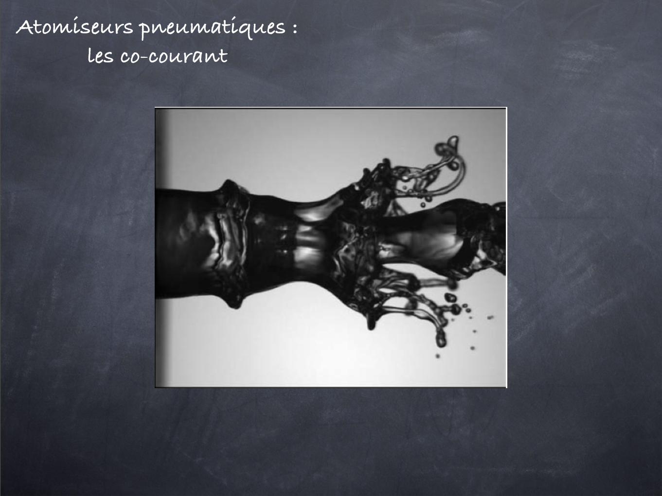
Atomiseurs pneumatiques : les co-courant
Atomiseurs pneumatiques : les jets transverses
Rep. Prog. Phys. 71 (2008) 036601 J Eggers and E Villermaux
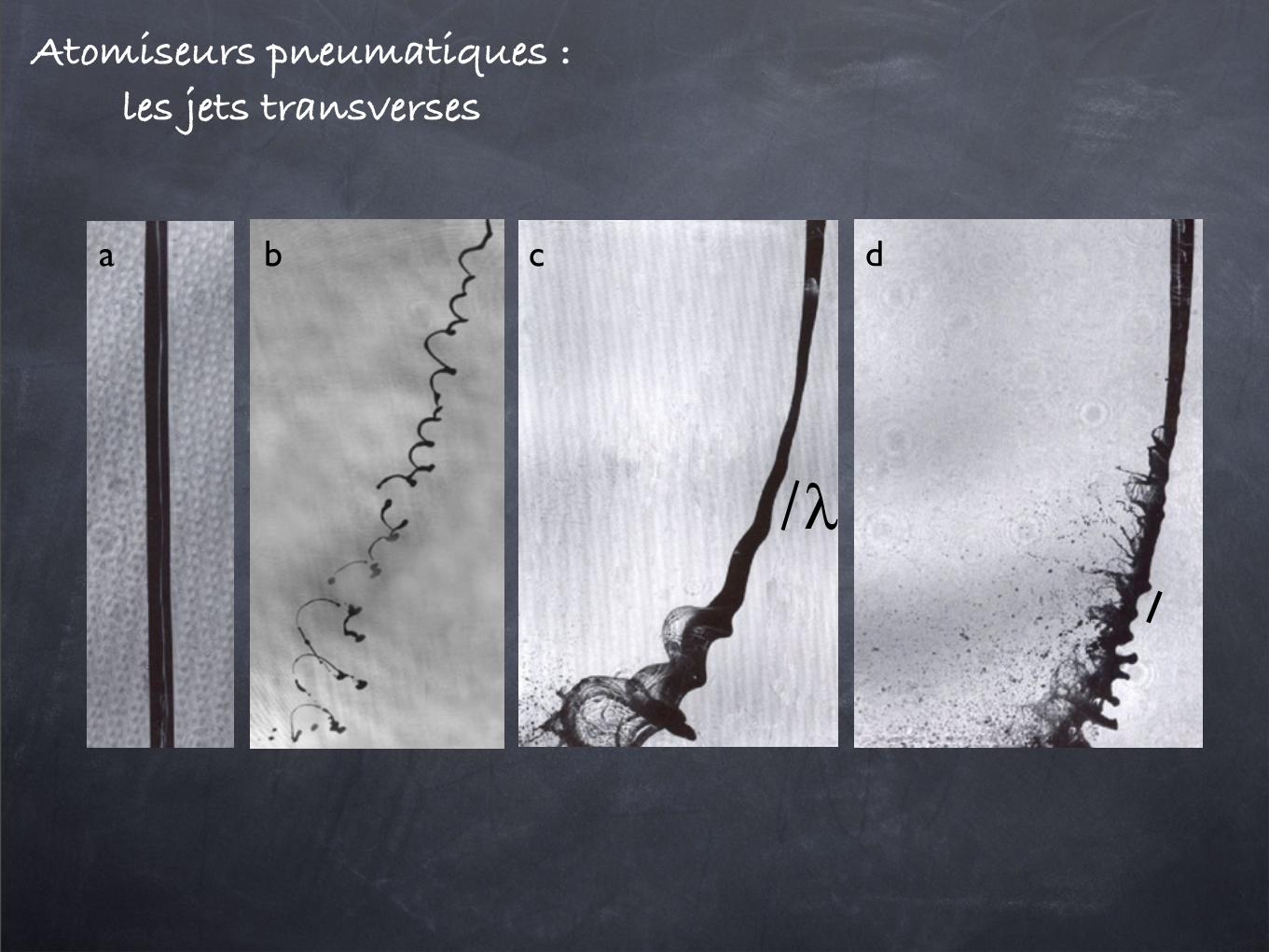
Figure 46. Liquid jet in a transverse cross flow of air. (a) Reference jet with no air, (b) We = 3, (c) We = 8, (d) We = 30 withWe = !au
2d/" as defined in (171). The jet diameter is millimetric and the liquid velocity v0 is of the order of a few 10 m s!1. The barindicates the length of the Rayleigh–Taylor wavelength #. Courtesy of K A Sallam [277].
The scaling law (171) has been checked by [277] over morethan two orders of magnitude in We, for different liquids andissuing velocities.
The above mechanism by which the liquid follows acurved base flow and thus sustains a centrifugal instability isreminiscent of the ‘wavy corridor’ mechanism, responsible forthe destabilization of undulated liquid sheets [278].
3.12. Liquid intact length
The minimum distance from the nozzle over which theliquid jet is still connected is usually called ‘liquid intactlength’ L [215,216,279]. This distance can fluctuate by severalwavelengths, but is defined in the mean. Scaling theories for L
are readily derived from the discussion in sections 3.2 through3.8. Namely, the intact length is
L = v0$, (173)
where $ is the characteristic time of the instability, needed tobreak the jet. Let us describe two simple extreme cases:
• For a pure capillary instability at negligible viscosity $ isgiven by (2), and thus
L
h0" We1/2, (174)
as is indeed observed for jets beyond the jetting transitionand entering a gaseous environment [119, 280, 281].
• For larger Weber number, the shear instability overcomesthe capillary destabilization (see section 3.8). Considerfor instance that the jet is ‘peeled off’ by an instabilityof the type sketched in figure 33, the injection velocityv0 also being the velocity contrast setting the shearintensity. This instability turnover time has been shown tobe Re[!i%i (km)]!1 " (&/v0)(!/!a), and the associatedwavelength k!1
m " &(!/!a)1/2. If these conditions are
maintained for several turnover times of the instability,the breakup time is
$ " h0km
!
!a
&
v0= h0
v0
!!
!a
"1/2
, (175)
leading to an intact length
L
h0"
!!
!a
"1/2
, (176)
independent of the jet velocity. This intact length canreach several hundred jet radii if !a/! # 1 [228, 231].Note that (176) is scale invariant and holds whatever &
may be. In other words, whatever the physical processwhich fixes & (which may be a boundary layer thicknessimposed externally, or an intrinsic wavelength " /!av
20 as
in section 3.8), L will always have the form (176), as soonas the jet destabilization is due to shear [231].
The overall dependence of L on the ejection velocity v0
for simple jets usually displays a linear increase at small v0,consistent with (174), and then a saturation whose level ishigher for a lighter environment, cf (176), and as seen infigure 47. Both dependences can be incorporated by sayingthat v0/L is the sum of the characteristic growth rates of eachof the competing instabilities, i.e.
v0
L= 1
#!v2
0/"+
&$
!/!a/h0
!/!a(&/v0). (177)
Thus, disregarding prefactors, we have
h0
L= 1$
We+
1$!a/!
, (178)
so the transition between the two limits occurs for a Webernumber of order
We " !
!a. (179)
In particular, at large Weber number L/h0 saturates at a valueproportional to
$!/!a, which is inversely proportional to
ambient gas pressure Pa. Data to support this conclusionare shown in figure 47. Contrary to a common belief since[238], this saturation is not an effect of viscosity on thecapillary instability development, but relates to the appropriateshear instability responsible for the jet peeling-off (see alsosection 3.8 and the point made in [236]).
34
Atomiseurs acoustiques
In 1917, Rayleigh described the first mathematicalmodel to explain the bubble collapse in incompressibleliquids, in his attempts to explain the physical mechanismsinvolved in ultrasound propagation in liquids (Rayleigh1917).
This was the current theoretical basis when Wood andLoomis (1927) discovered the possibility of atomizingliquids by exciting them with ultrasonic waves. An expla-nation for this process was proposed by Sollner (1936a)based on cavitation produced under the liquid film.However, numerous later works (Bisa et al. 1954; Benjaminand Ursell 1954; Sorokin 1957; Eisenmenger 1959) pointedto unstable surface capillary waves as the origin of thedroplet formation, mostly relying on simplified linear in-stability analysis. In 1962, Lang published detailed exper-imental research presenting his famous expression relatingwavelength to droplet size through an empirical constantk, whose value obtained fitting his experimental mea-surements was reported to be 0.34, placed in front ofEq. (2) (Lang 1962). His experiments were performed forfrequencies up to 800 kHz. A more elaborated theoreticalmodel based on interfacial Taylor instability triggering thesurface waves was later developed by Peskin and Raco(1963). Together with the wavelength, they introduced thewave amplitude and the sheet thickness as parametersdetermining the droplet diameter.
The atomization theory based on cavitation, abandonedduring this period, was resumed by Eknadiosyants andcoworkers (Gersherson and Eknadiosyants 1964; Ekna-diosyants 1968). After these, several studies have tried tocombine both theories (Fogler and Timmerhaus 1965;Boguslaskii and Eknadiosyants 1969; Topp 1973; Chiba1975; Basset and Bright 1976), some of them indicatingthat the prevalence of each one might depend on theultrasonic intensity.
These explanations are still subject to controversy, andpapers on this topic continue to be published from bothexperimental (Edwards and Fauve 1994; Sindayiheburaet al. 1997) and theoretical (Miles 1994; Sindayihebura andBolle 1998) approaches.
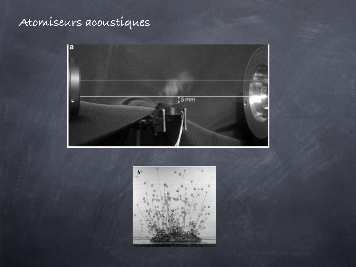
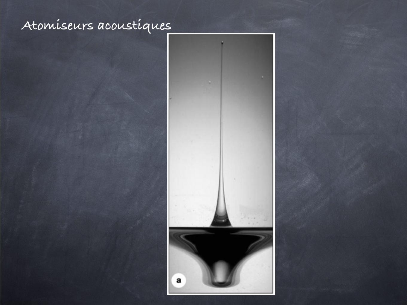
3Description of the experimentWater was atomized, depositing small amounts over anultrasonic transducer. The transducer, shown in Fig. 1, isformed by a PZT 4 piezoceramic disk with a diameter of20 mm and a thickness of 1.3 mm. The resonance fre-quency of this disk was measured to be 1.65 MHz. Thedisk was excited with a sinusoidal wave coincident withthe resonance frequency and variable amplitude. Themaximum voltage that could be delivered without dam-aging the ceramic was 50 V. For voltages below 15 V, noatomization was observed. The atomization process isdisplayed in Fig. 2a.
To visualize the atomization process, images were ac-quired with a Princeton Instruments (division of RoperScientific, Trenton, N.J.) CCD camera. To freeze the mo-tion, the flow was illuminated with 6-ns pulses from adouble cavity Quantel (Les Ulis, France) YG781C-10Nd:YAG laser. The optical system was arranged to operatewith high magnification to resolve the small droplets. An
inverted 50-mm Nikon (Tokyo, Japan) lens attached to abellows extension was used, as well as a Questar QM100telemicroscope (Questar Corporation, New Hope, Pa.).Different areas were imaged with these configurations.They are depicted in Fig. 2b: zone a is 2.9·2.1 mm, zone bis 1.45·1.9 mm, zone c is 1.5·1.5 mm, while zone d is0.5·0.75 mm. A maximum resolution of 2 lm/pixel wasachieved. Top and side views of the vibrating disk withwater were obtained to observe the liquid surface and theair/water interface. For the side views, the flow was illu-minated by a 5-cm-high laser sheet, with a thickness of0.5 mm. In some cases, to avoid laser reflections, a
Fig. 1. Image of the piezoceramic disk used in the presentexperiments
Fig. 2. a Image of the disk during the atomization process, withindication of the diffractometer laser beam position. b Sketch of theexperiment indicating size and approximate location of the differentzones registered in the images in this work. Sizes are: a 2.9·2.1 mm;b 1.45·1.9 mm; c 1.5·1.5 mm; d 0.5·0.75 mm
406
which the free-surface breakup is dominated by the firstseparation at the base of the spike. The initial drop atomiza-tion generates elongated liquid threads and the spray isformed only after secondary breakup and recoil of thesethreads.
Depending on the initial aspect ratio of the separatedthread, fluid properties, and the initial momentum of thespike, thread breakup may form single or multiple satellitedroplets. It is also possible for the thread to recoil into asingle large droplet without any breakup. Therefore, it isclear that the high-Ca atomization regime generates a widerange of droplet sizes and velocities making the resultingspray characteristics more dispersed than the spray formed inthe low-Ca regime !Fig. 7"a#$. Here, the majority of droplets
ejected from the free surface result from successive capillarypinch-off events from the tips of liquid spikes, so that thedistribution of droplet sizes is more uniform.
A typical breakup process for an extended liquid threadin the high-Ca regime is shown in the sequence of high-speed images in Fig. 8. A glycerin-water drop "liquid-solution 5, Table I# is forced at f =1030 Hz and at a forcingamplitude slightly above the droplet-ejection accelerationthreshold ac. As the nearly cylindrical spike elongates withthe slowed formation of the bulbous tip, the first breakupoccurs at its base "marked by the triangle#, and a long, sepa-rated liquid thread with initially upward momentum forms.Due to the initially high surface curvature at the point ofbreakup, another bulbous tip forms immediately on the lowerend of the thread. As the lower end of the separated threadcontinues to retract, the bulbous tip at the top of the threadundergoes capillary pinch-off "marked by the triangle#. Thiscreates a droplet that travels away from the drop. The re-maining thread recoils into a single satellite droplet.
Using the tracking technique described in Sec. II, trajec-tories for three characteristic points on the breaking spikeshown in Fig. 8 are plotted in Fig. 9, along with some of thecorresponding snap shots. The time for the first recordedoccurrence of the spike is initially marked as t0=0, and thetip trajectory is tracked in time relative to the absolute "dropsupport# level "ha=0#. The trajectory of the tail of the sepa-rated thread is tracked along with that of the tip, and is ap-proximately linear in time. This suggests that the absolutevelocity of the tail is approximately constant, with decelera-tion of the entire thread approximately balanced by the ac-celeration of the recoiling tail. Following the first breakup at
FIG. 7. Liquid spray formation during atomization of a 0.1 ml drop forcedat 1030 Hz: "a# water "!=1 cP# and "b# glycerin-water solution"!=79.7 cP#.
FIG. 8. "Color online# A sequence of consecutive images showing thebreakup of a spike that emanates from the free surface of a 0.1 ml glycerin-water drop "solution 5, Table I# that is forced at 1030 Hz. The image se-quence proceeds from left to right and top to bottom. It was recorded at2000 fps.
012104-9 Mechanisms of free-surface breakup Phys. Fluids 19, 012104 !2007"
Downloaded 21 Sep 2009 to 134.157.34.224. Redistribution subject to AIP license or copyright; see http://pof.aip.org/pof/copyright.jsp
Atomiseurs acoustiques
Atomiseurs effervescents1.1 Atomisation : etat de l’art 9
(a) (b)
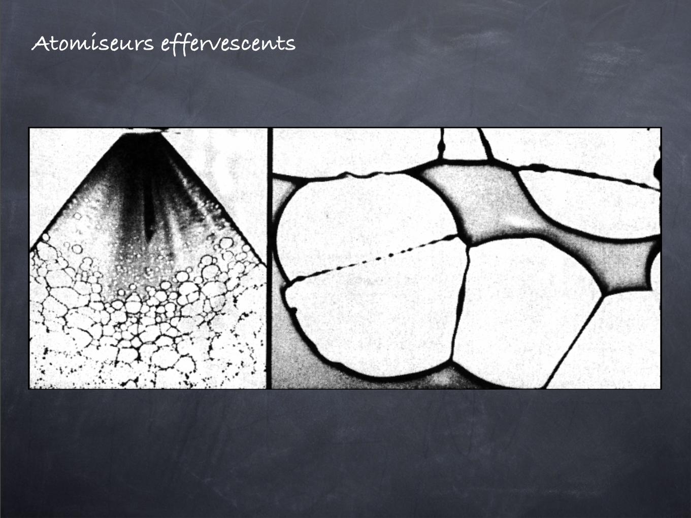
Fig. 1.10: (a) : fragmentation sous forme de trou d’une nappe formee apartir d’une emulsion d’eau et d’huile. (b) : vue detaillee de la fragmentation,d’apres Dombrowski et Fraser [17].
la tension superficielle, puis se connectent a leurs voisins par l’intermediaired’un ligament qui se brise en gouttes. Le diametre du ligament, et donc lataille des gouttes, depend de l’epaisseur de la nappe ainsi que de la repar-tition spatiale des trous. L’apparition de trous dans la nappe peut etre leresultat de fortes modulations locales d’epaisseur causees par des variationsde vitesse dans le cas d’un ecoulement turbulent [58]. Dans le cas de nappesformees par la collision de deux jets turbulents de diametre moyen dj et devitesse moyenne uj , la fragmentation de la nappe est periodique [36, 18]. Lafrequence de l’atomisation de la nappe varie comme dj/uj. Cette frequenceest a rapprocher de celle du mode prefere du jet pour des grandes vitessesd’injection [39]. La fragmentation est localisee dans une region proche del’impact, ce qui donne une grande importance aux conditions d’injection.
1.1.3 Contexte industriel
L’etude experimentale de la these s’insert dans un programme franco-allemand portant sur les instabilites hautes frequences dans les moteurs fu-see utilisant des liquides. Le programme de recherche rassemble le CNES,CNRS, DLR, ONERA, SECMA et ASTRIUM. Le but est de comprendre lescouplages entre l’atomisation des combustibles, la combustion et l’acoustiquedans les moteurs. Du point de vue de l’atomisation, l’une des questions estde savoir si une eventuelle fragmentation spatio-temporelle du combustiblepeut entraıner une combustion oscillante excitant des modes acoustiques dela chambre a combustion. Dans l’hypothese d’un tel scenario, le champ depression pourrait a son tour modifier les conditions d’atomisation et conduirea une instabilite entraınant une deterioration du materiel. Une revue des dif-ferents problemes physiques et chimiques lies aux instabilites de combustiondans les moteurs fusees est presentee par Yang et Anderson [104].
tel-00011518, vers
ion 1
- 1
Feb 2
006
Atomiseurs électrostatiques
Rep. Prog. Phys. 71 (2008) 036601 J Eggers and E Villermaux
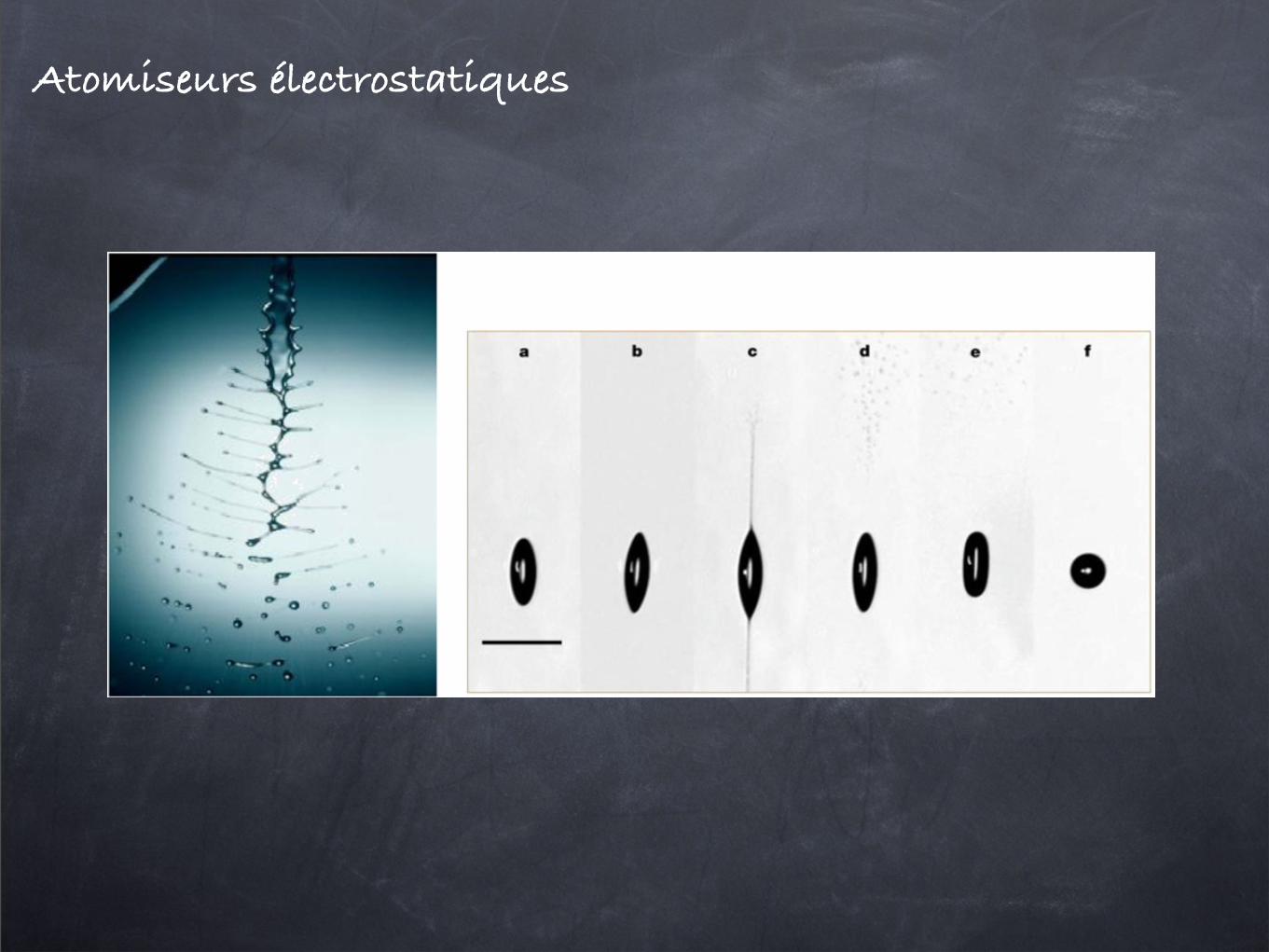
Figure 40. (Left) Instantaneous realization of the electrostatic disruption of room-temperature paraffinic white oil. The oil is issuing at5 ml s!1 from a circular orifice (h0 = 0.5 mm) after having been negatively charged to a mean charge density of 0.15 Cb m!3. The liquid ischarged by a submerged electrode, which is positioned immediately upstream of the grounded orifice through which the fluid issues. In theabsence of charge injection the liquid would exit as a glassy smooth cylindrical stream. The elegant filamentary structure and subsequentdroplet development is purely electrostatic. No mechanical or aerodynamic forces are involved. Reprinted with permission from [239],copyright 2000 by the American Institute of Physics. (Right) High-speed imaging of the disintegration of a levitated droplet charged to theRayleigh limit. The droplet (radius, 24 µm) is imaged at !t values (in µs) of: a, 140; b, 150; c, 155; d, 160; e, 180 and f, 210. The dropletchanges from a sphere to an ellipsoid (a), tips appear at the poles (b) and a fine jet of liquid is ejected from each tip (c); the jets disintegrate(d) and the elliptical droplet re-assumes a spherical shape (e), (f). Scale bar, 100 µm. Reprinted from [240], copyright 2003, withpermission from Nature Publishing Group.
0 0.5 1 1.5 2
0.1
0.2
0.3
0.4
0.5
Figure 41. Stability curve !i"# versus kh0. Destabilizing effect ofsurface charges with $ = 2 on the varicose mode m = 0 inequation (150). The neutral jet dispersion curve is shown forcomparison.
which may even lead to ‘jet splitting’ in some cases (see [250]and references therein).
The stability of a charged jet in an external electric fieldis of the utmost importance for applications. If the jet breaksup into droplets, one speaks of ‘electrospraying’. Anotherpossibility is the whipping mode shown in figure 42, on whichthe ‘electrospinning’ technique of producing polymer fibres isbased [251–253], for example to make fabrics. The stability ofa cylindrical jet, reviewed in [247,254], now depends not onlyon the fluid parameters %i and K but also on external parameterssuch as the applied electric field and the surface charge, to bedetermined from the cone-jet solution. The problem becomesmanageable in a long-wavelength description [247], which isself-consistent in most cases.
Apart from a modified Rayleigh mode, which is graduallysuppressed as the electric field is increased, another varicose
‘conducting’ mode becomes increasingly unstable, whichcomes from the redistribution of surface charges. A third‘whipping’ mode is most significant for large surface charges:namely, imagine three like charges on a line. A lower energystate is achieved if the middle charge breaks out of line, so thejet is no longer straight. For a quantitative analysis, the axialvariations of h(z) and & (z) must be taken into account [248], sothe stability depends significantly on the downstream distance.With this in mind, the onset of whipping can be predictedquantitatively [248].
Charges also play an important role for the stability ofnuclei [255], which may be modelled as charged liquid drops[256] or, in a more extended state, jets [257]. The stabilityof uniformly charged jets was investigated in [258], and itsrelevance to the stability and the breakup of nuclei is discussedat length in [257].
3.10. Ferrofluids in a magnetic field
Ferrofluids are colloidal dispersions of small (typicallymicrometre-sized) magnetized dipolar particles which arespread out in a continuous, liquid phase. Application ofan external magnetic field H induces a magnetization of thedispersion M = 'H, where ' is the magnetic susceptibilityof the medium, such that the net induction field is B = µH =µ0(1 + ')H, with µ the permeability of the medium and µ0
that of vacuum. The resulting stresses lead to an additionalbody force in the Navier–Stokes equation, which adds a termµ0M!H to the internal pressure gradient. Rosensweig [259]gives a comprehensive exposition of these notions, illustratedby many examples including the two discussed below.
3.10.1. Parallel field. A magnetic field H0 appliedperpendicular to a free plane magnetic fluid interface leadsto an instability very similar to a Rayleigh–Taylor instability[219, 259], because of the magnetic susceptibility jump,
30

Diagnostics de qualité
L’angle du spray
La profondeur de pénétration
La distribution de liquide
La distribution de tailles de gouttes
Le diamètre moyen de Sauter
4.2 Efficacité de l’atomisation. Diagnostics de qualité.Nous passons maintenant brièvement en revue différents diagnostics de qualité des atomiseurs.
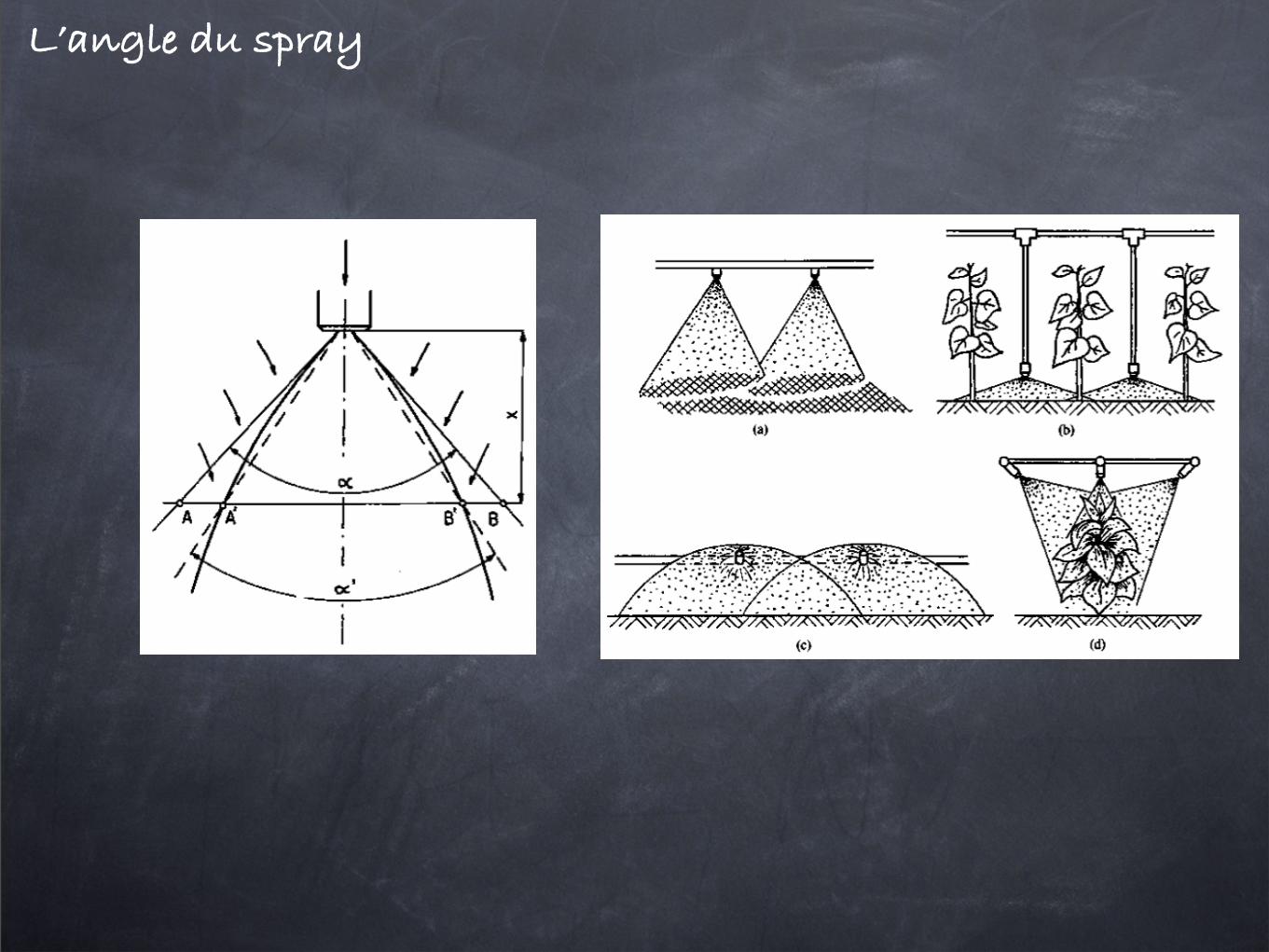
4.2.1 Structure macroscopiqueL’angle du spray
À plusieurs reprises nous avons vu apparaître la notion d’angle de spray. Celui-ci varie dans des proportions
considérables en fonction des atomiseurs. Depuis quelques degrés dans les injecteurs Diesel jusqu’aux ou-
vertures considérables des atomiseurs tournants, ce paramètre est important par exemple pour dimensionner
correctement une installation agricole et ne pas laisser de zones hors de portée des atomiseurs. Dans d’autres
applications, ce paramètre peut devenir critique ; c’est le cas par exemple des turbines de moteur à réaction
où un fort écoulement tournant crée une zone de stagnation. L’injecteur est conçu de façon à d’adapter à cette
zone de stagnation.
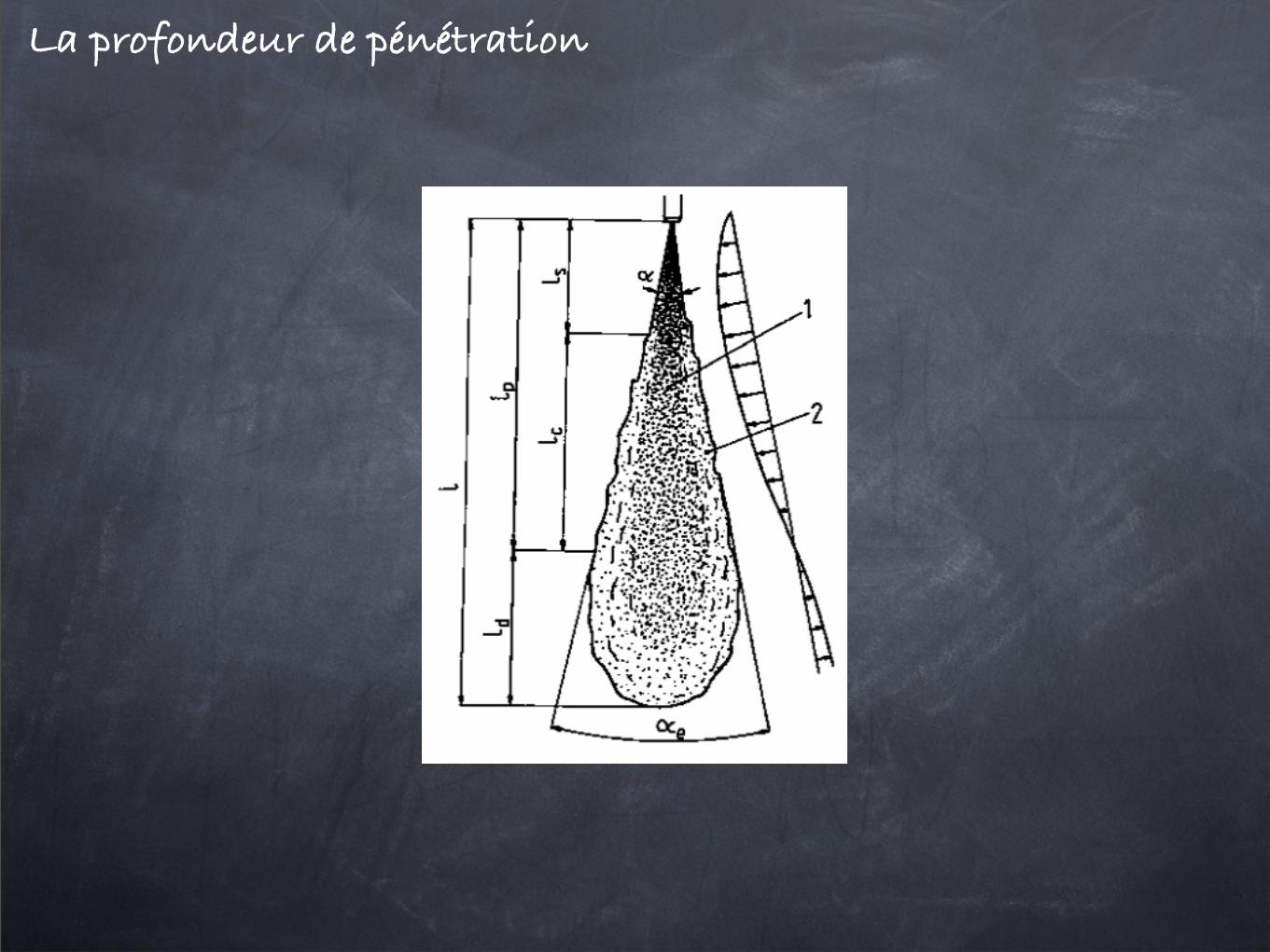
La profondeur de pénétration
La longueur de pénétration d’un spray est une autre caractéristique importante des atomiseurs, dimension-
nante dans le cas des chambres de combustion (il n’est pas souhaitable que le panache vienne percuter une
paroi ou un piston).
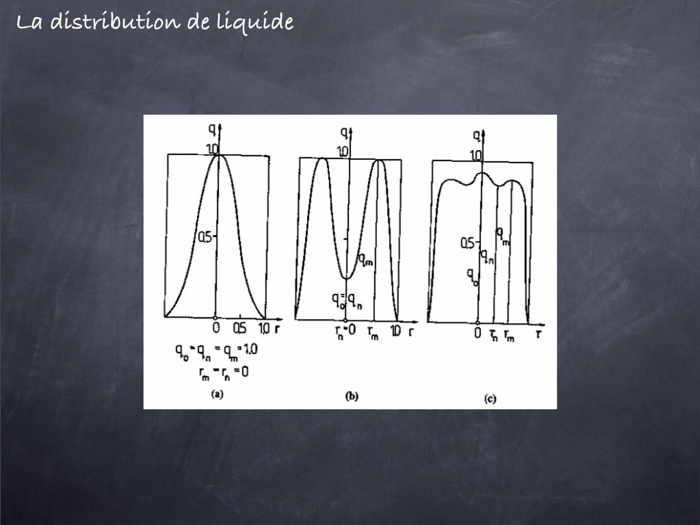
La distribution de liquide
La grande ouverture des atomiseurs tournants cache en réalité toute une zone non alimentée au centre du
cône. À cette fin, il est souhaitable de connaître la distribution de liquide, soit radialement afin de quantifier
les non-uniformités du brouillard généré, soit azimutalement afin de statuer sur la symétrie du brouillard.
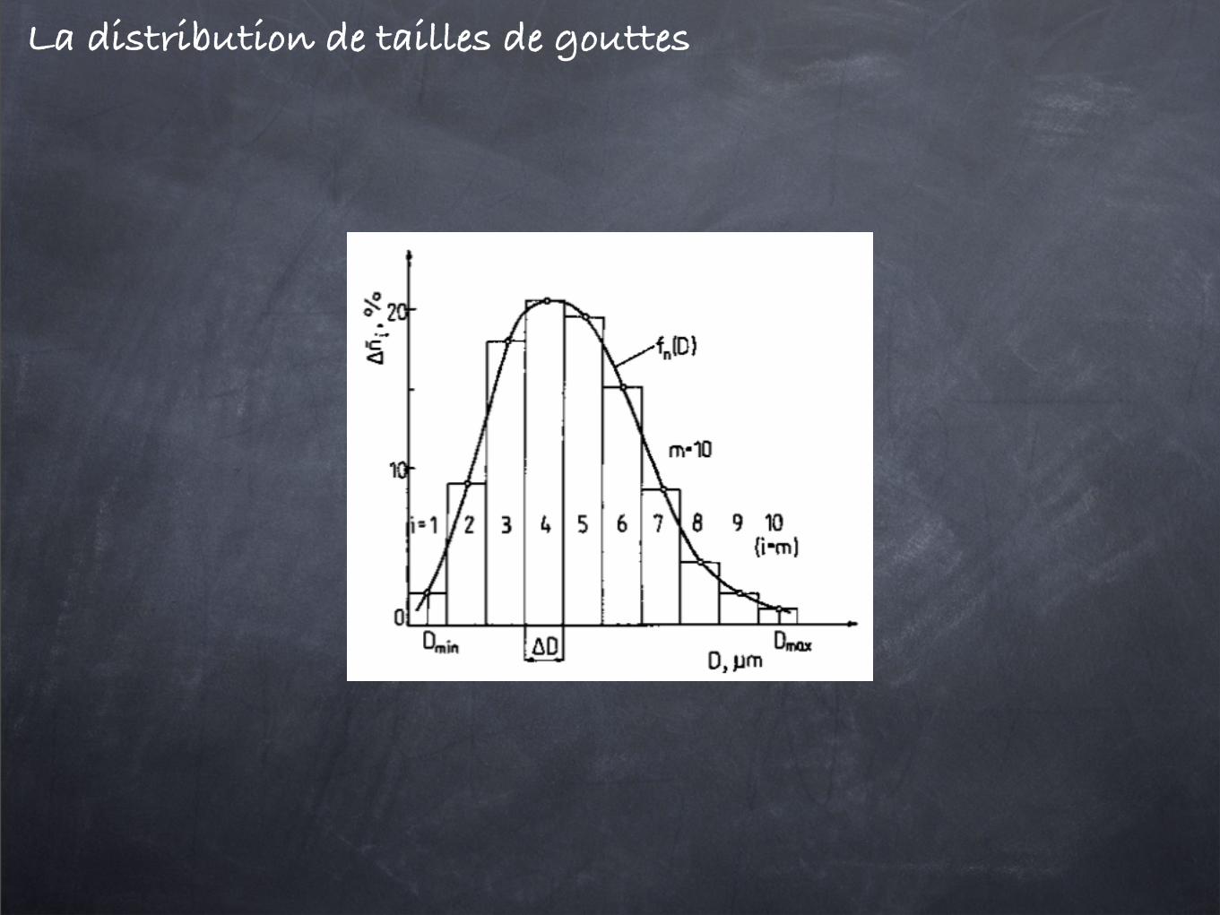
4.2.2 Structure microscopiqueLa distribution de tailles de gouttes
La plupart des atomiseurs génèrent des gouttes distribuées en tailles. C’est là un inconvénient dans beau-
coup de situations. Cette non-uniformité apparaît cependant à des dégrés divers. Ainsi il existe une large
gamme de diamètres moyens (degré d’atomisation) accessibles, associés à une large gamme de dispersion en
taille (uniformité de l’atomisation). Ces deux paramètres forment la qualité de l’atomisation.
Ces paramètres sont directement accessibles grâce à la distribution de tailles de gouttes du spray. La distribu-
tion de tailles s’obtient en représentant le nombre de gouttes dn ayant un diamètre compris entre d et d + dd.
Cette probabilité s’écrit souvent sous la forme p(d)dd. p(d) est la distribution de tailles de gouttes.
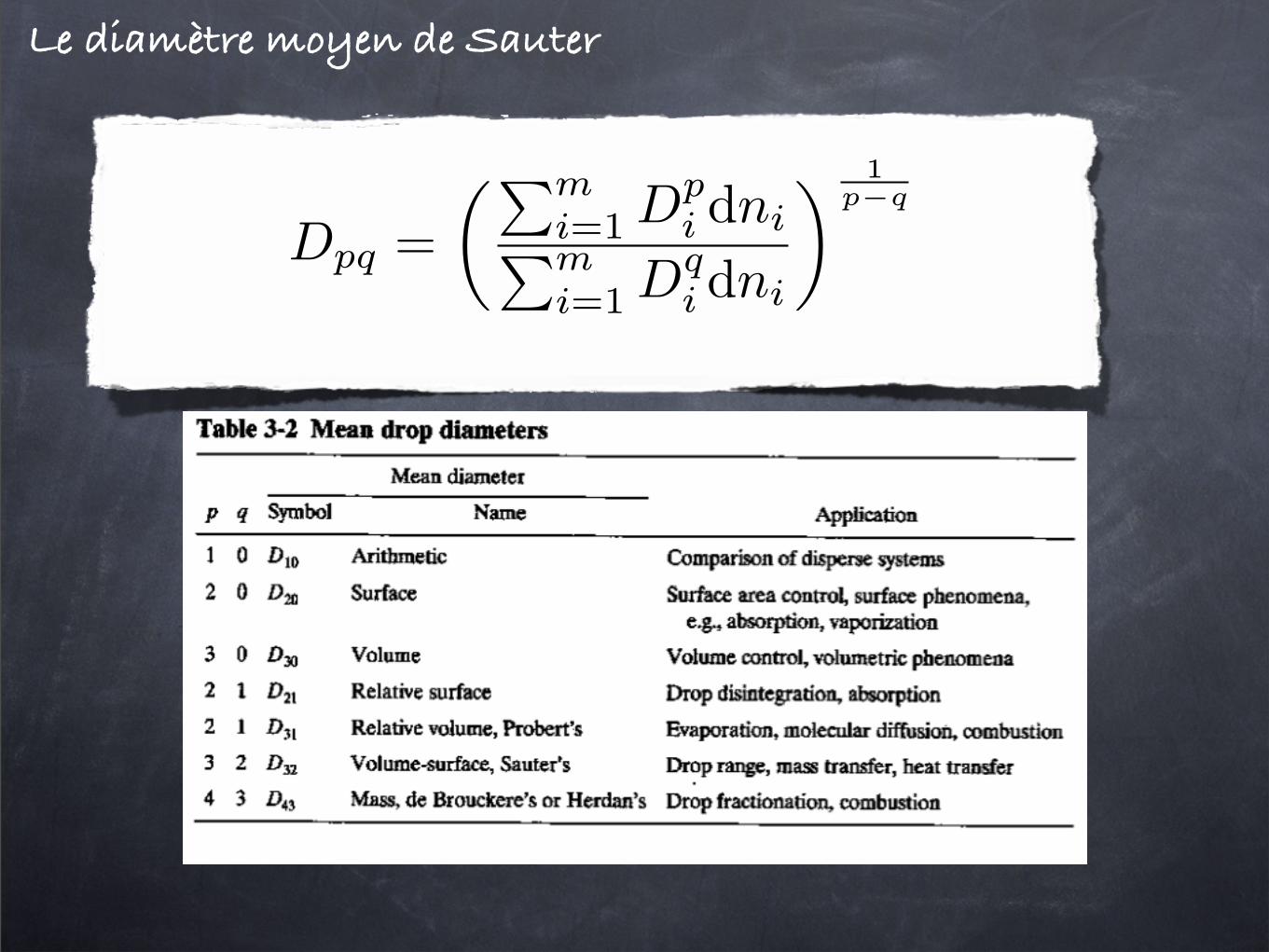
Le diamètre moyen de Sauter
Il est d’usage d’estimer la performance d’un atomiseur à partir d’une seule quantité construite comme suit
Dpq =��m
i=1 Dpi dni�m
i=1 Dqi dni
� 1p−q
(4.1)
la distribution de vitesse
VERSION PROVISOIRE 49

La distribution des vitesses