Embed Size (px)
Citation preview
2/9/2016
1
© 2013 Pearson Education, Inc.
Chapter 22 Wave Optics
Chapter Goal: To understand and apply the wave model of light.Slide 22-2
© 2013 Pearson Education, Inc.
Chapter 22 Preview
Slide 22-3
© 2013 Pearson Education, Inc.
Chapter 22 Preview
Slide 22-4
2/9/2016
2
© 2013 Pearson Education, Inc.
Chapter 22 Preview
Slide 22-5
© 2013 Pearson Education, Inc.
Chapter 22 Preview
Slide 22-6
© 2013 Pearson Education, Inc.
Chapter 22 Preview
Slide 22-7

2/9/2016
3
© 2013 Pearson Education, Inc.
Chapter 22 Reading Quiz
Slide 22-8
© 2013 Pearson Education, Inc.
What was the first experiment to show that light is a wave?
A. Young’s double-slit experiment.
B. Galileo’s observation of Jupiter’s moons.
C. The Michelson-Morley interferometer.
D. The Pound-Rebka experiment.
E. Millikan’s oil-drop experiment.
Reading Question 22.1
Slide 22-9
© 2013 Pearson Education, Inc.
What is a diffraction grating?
A. A device used to grate cheese and other materials.
B. A musical instrument used to direct sound.
C. An opaque screen with a tiny circular aperture.
D. An opaque screen with many closely spaced slits.
E. Diffraction gratings are not covered in Chapter 22.
Reading Question 22.2
Slide 22-11
2/9/2016
4
© 2013 Pearson Education, Inc.
When laser light shines on a screen after passing through two closely spaced slits, you see
A. A diffraction pattern.
B. Interference fringes.
C. Two dim, closely spaced points of light.
D. Constructive interference.
Reading Question 22.3
Slide 22-13
© 2013 Pearson Education, Inc.
This chapter discussed the
A. Acoustical interferometer.
B. Michelson interferometer.
C. Fabry-Perot interferometer.
D. Both A and B.
E. Both B and C.
Reading Question 22.4
Slide 22-15
© 2013 Pearson Education, Inc.
The spreading of waves behind an aperture is
A. More for long wavelengths, less for short wavelengths.
B. Less for long wavelengths, more for short wavelengths.
C. The same for long and short wavelengths.
D. Not discussed in this chapter.
Reading Question 22.5
Slide 22-17

2/9/2016
5
© 2013 Pearson Education, Inc.
Apertures for which diffraction is studied in this chapter are
A. A single slit.
B. A circle.
C. A square.
D. Both A and B.
E. Both A and C.
Reading Question 22.6
Slide 22-19
© 2013 Pearson Education, Inc.
Chapter 22 Content, Examples, and
QuickCheck Questions
Slide 22-21
© 2013 Pearson Education, Inc.
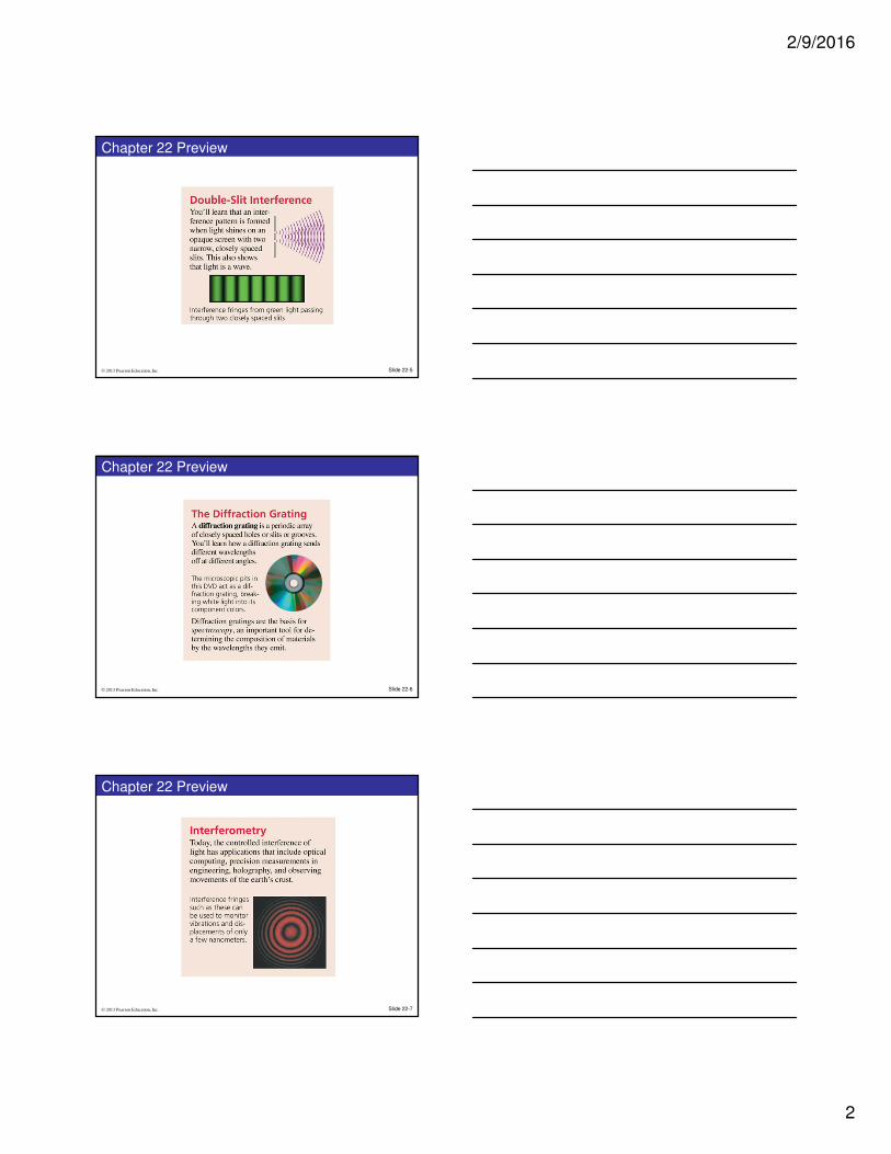
Diffraction of Water Waves
� A water wave, after passing through an opening, spreads
out to fill the space
behind the opening.
� This well-known spreading of waves is called diffraction.
Slide 22-22
2/9/2016
6
© 2013 Pearson Education, Inc.
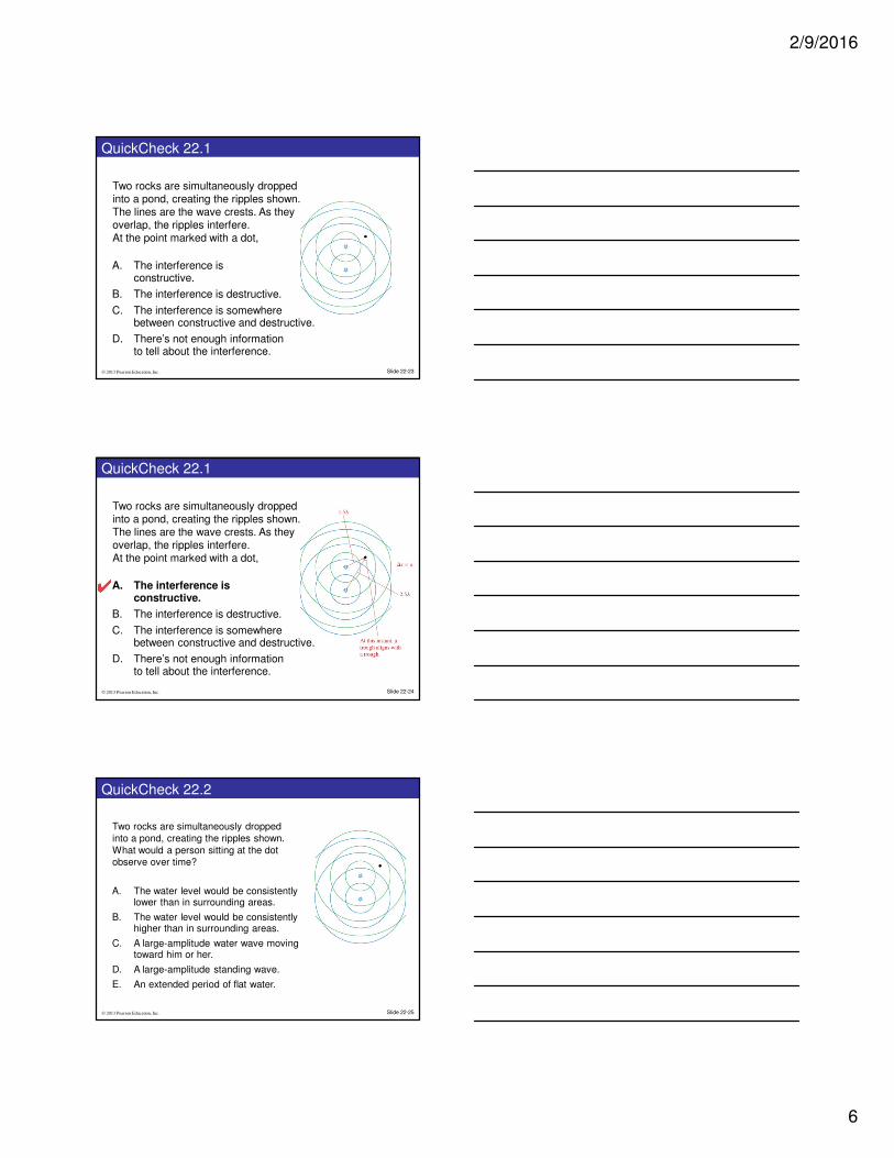
Two rocks are simultaneously dropped into a pond, creating the ripples shown. The lines are the wave crests. As they overlap, the ripples interfere. At the point marked with a dot,
QuickCheck 22.1
A. The interference is constructive.
B. The interference is destructive.
C. The interference is somewhere between constructive and destructive.
D. There’s not enough information to tell about the interference.
Slide 22-23
© 2013 Pearson Education, Inc.
Two rocks are simultaneously dropped into a pond, creating the ripples shown. The lines are the wave crests. As they overlap, the ripples interfere. At the point marked with a dot,
QuickCheck 22.1
A. The interference is constructive.
B. The interference is destructive.
C. The interference is somewhere between constructive and destructive.
D. There’s not enough information to tell about the interference.
Slide 22-24
© 2013 Pearson Education, Inc.
Two rocks are simultaneously dropped
into a pond, creating the ripples shown.
What would a person sitting at the dot observe over time?
QuickCheck 22.2
A. The water level would be consistently lower than in surrounding areas.
B. The water level would be consistently higher than in surrounding areas.
C. A large-amplitude water wave moving toward him or her.
D. A large-amplitude standing wave.
E. An extended period of flat water.
Slide 22-25
2/9/2016
7
© 2013 Pearson Education, Inc.
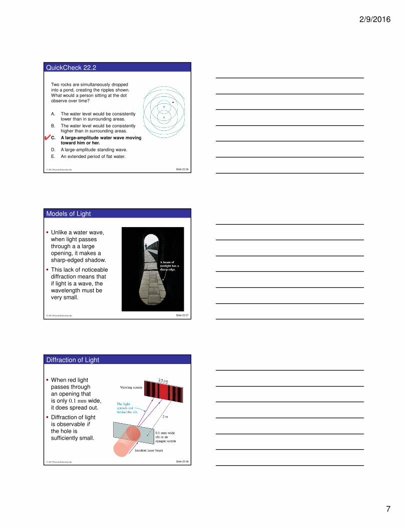
Two rocks are simultaneously dropped
into a pond, creating the ripples shown.
What would a person sitting at the dot observe over time?
QuickCheck 22.2
A. The water level would be consistently lower than in surrounding areas.
B. The water level would be consistently higher than in surrounding areas.
C. A large-amplitude water wave moving toward him or her.
D. A large-amplitude standing wave.
E. An extended period of flat water.
Slide 22-26
© 2013 Pearson Education, Inc.
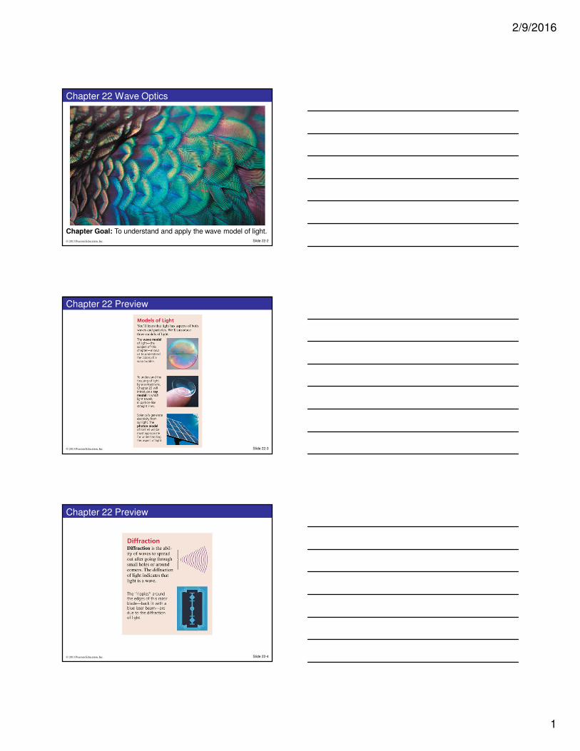
Models of Light
� Unlike a water wave, when light passes
through a a large opening, it makes a sharp-edged shadow.
� This lack of noticeable diffraction means that
if light is a wave, the wavelength must be very small.
Slide 22-27
© 2013 Pearson Education, Inc.
Diffraction of Light
� When red light passes through
an opening that is only 0.1 mm wide, it does spread out.
� Diffraction of light is observable if
the hole is sufficiently small.
Slide 22-28
2/9/2016
8
© 2013 Pearson Education, Inc.
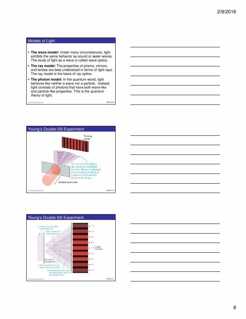
Models of Light
� The wave model: Under many circumstances, light exhibits the same behavior as sound or water waves. The study of light as a wave is called wave optics.
� The ray model: The properties of prisms, mirrors, and lenses are best understood in terms of light rays. The ray model is the basis of ray optics.
� The photon model: In the quantum world, light behaves like neither a wave nor a particle. Instead, light consists of photons that have both wave-like and particle-like properties. This is the quantum theory of light.
Slide 22-29
© 2013 Pearson Education, Inc.
Young’s Double-Slit Experiment
Slide 22-30
© 2013 Pearson Education, Inc.
Young’s Double-Slit Experiment
Slide 22-31
2/9/2016
9
© 2013 Pearson Education, Inc.
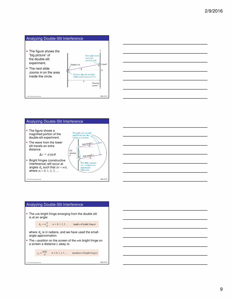
Analyzing Double-Slit Interference
� The figure shows the “big picture” of
the double-slit experiment.
� The next slide zooms in on the area inside the circle.
Slide 22-32
© 2013 Pearson Education, Inc.
Analyzing Double-Slit Interference
� The figure shows a magnified portion of the double-slit experiment.
� The wave from the lower slit travels an extra distance.
� Bright fringes (constructive interference) will occur at angles θm such that ∆r = mλ, where m = 0, 1, 2, 3, …
Slide 22-33
© 2013 Pearson Education, Inc.
Analyzing Double-Slit Interference
� The mth bright fringe emerging from the double slit is at an angle:
where θm is in radians, and we have used the small-angle approximation.
� The y-position on the screen of the mth bright fringe on a screen a distance L away is:
Slide 22-34

2/9/2016
10
© 2013 Pearson Education, Inc.
A laboratory experiment produces a double-slit interference pattern on a screen. The point on the screen marked with a dot is how much farther from the left slit than from the right slit?
A. 1.0 λ.
B. 1.5 λ.
C. 2.0 λ.
D. 2.5 λ.
E. 3.0 λ.
QuickCheck 22.3
Slide 22-35
© 2013 Pearson Education, Inc.
A laboratory experiment produces a double-slit interference pattern on a screen. The point on the screen marked with a dot is how much farther from the left slit than from the right slit?
A. 1.0 λ.
B. 1.5 λ.
C. 2.0 λ.
D. 2.5 λ.
E. 3.0 λ.
QuickCheck 22.3
Slide 22-36
© 2013 Pearson Education, Inc.
A laboratory experiment produces a double-slit interference pattern on a screen. If the screen is moved farther away from the slits, the fringes will be
A. Closer together.
B. In the same positions.
C. Farther apart.
D. Fuzzy and out of focus.
QuickCheck 22.4
Slide 22-37

2/9/2016
11
© 2013 Pearson Education, Inc.
A laboratory experiment produces a double-slit interference pattern on a screen. If the screen is moved farther away from the slits, the fringes will be
A. Closer together.
B. In the same positions.
C. Farther apart.
D. Fuzzy and out of focus.
QuickCheck 22.4
Slide 22-38
© 2013 Pearson Education, Inc.
Example 22.1 Double-Slit Interference of a
Laser Beam
VISUALIZE The interference pattern is symmetrical, with m = 2 bright
fringes at equal distances on both sides of the central maximum.
Slide 22-39
© 2013 Pearson Education, Inc.
Example 22.1 Double-Slit Interference of a
Laser Beam
Slide 22-40
2/9/2016
12
© 2013 Pearson Education, Inc.
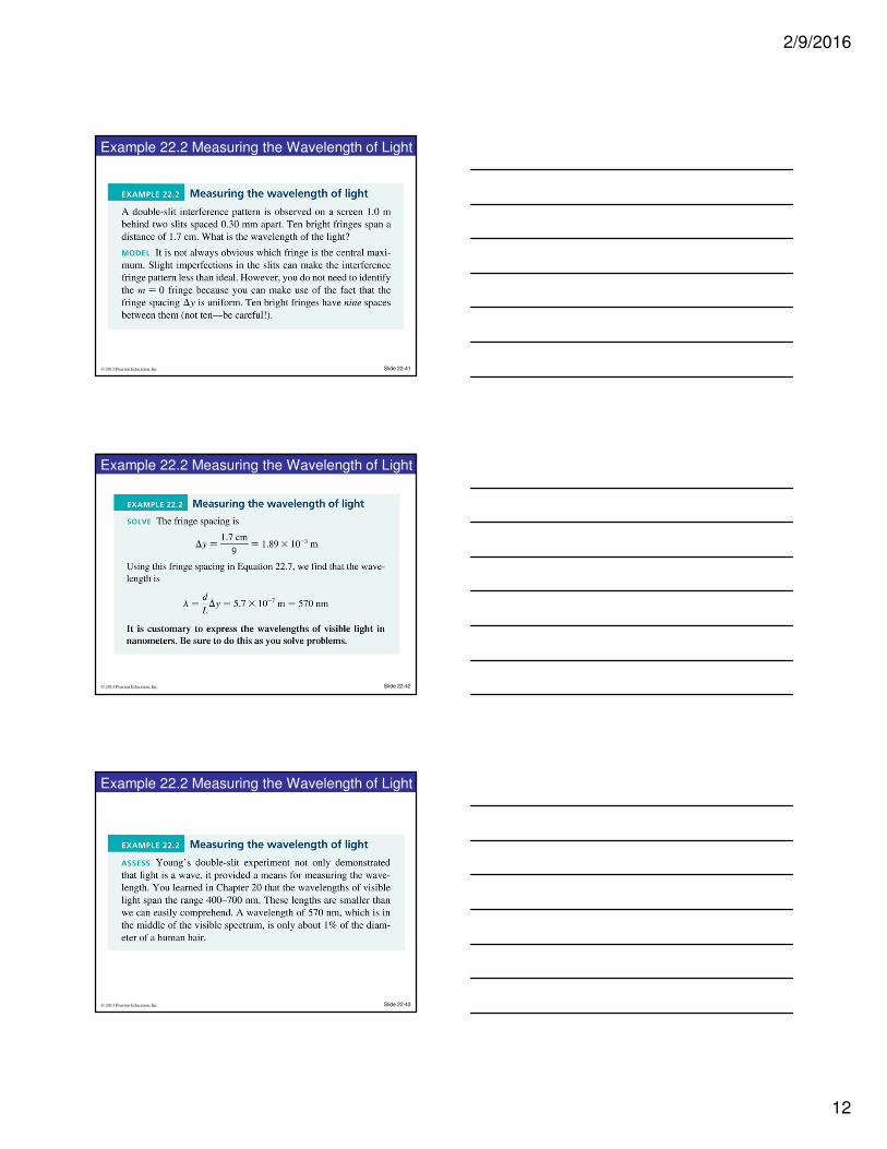
Example 22.2 Measuring the Wavelength of Light
Slide 22-41
© 2013 Pearson Education, Inc.
Example 22.2 Measuring the Wavelength of Light
Slide 22-42
© 2013 Pearson Education, Inc.
Example 22.2 Measuring the Wavelength of Light
Slide 22-43
2/9/2016
13
© 2013 Pearson Education, Inc.
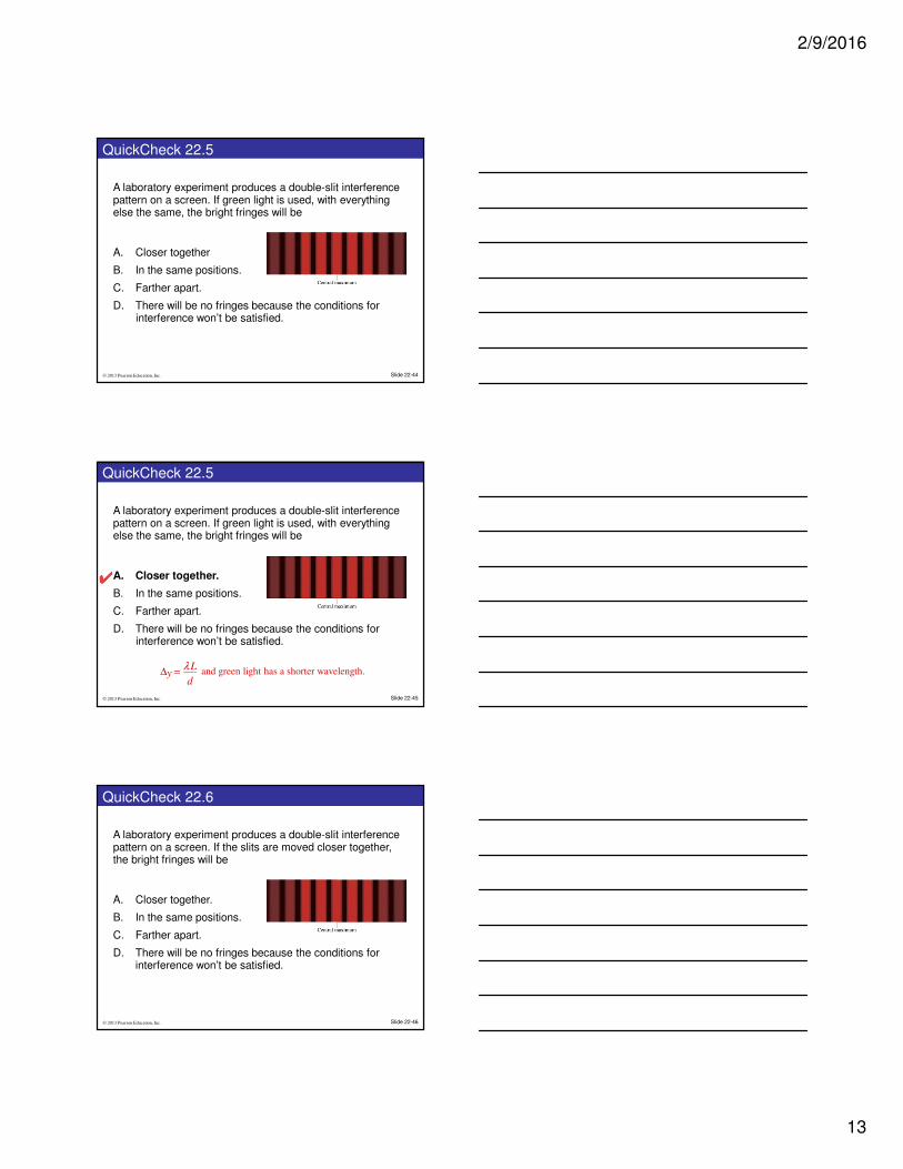
A laboratory experiment produces a double-slit interference pattern on a screen. If green light is used, with everything else the same, the bright fringes will be
QuickCheck 22.5
A. Closer together
B. In the same positions.
C. Farther apart.
D. There will be no fringes because the conditions for interference won’t be satisfied.
Slide 22-44
© 2013 Pearson Education, Inc.
A laboratory experiment produces a double-slit interference pattern on a screen. If green light is used, with everything else the same, the bright fringes will be
QuickCheck 22.5
d∆y =
λ Land green light has a shorter wavelength.
A. Closer together.
B. In the same positions.
C. Farther apart.
D. There will be no fringes because the conditions for interference won’t be satisfied.
Slide 22-45
© 2013 Pearson Education, Inc.
A laboratory experiment produces a double-slit interference pattern on a screen. If the slits are moved closer together, the bright fringes will be
QuickCheck 22.6
A. Closer together.
B. In the same positions.
C. Farther apart.
D. There will be no fringes because the conditions for interference won’t be satisfied.
Slide 22-46

2/9/2016
14
© 2013 Pearson Education, Inc.
A laboratory experiment produces a double-slit interference pattern on a screen. If the slits are moved closer together, the bright fringes will be
QuickCheck 22.6
A. Closer together.
B. In the same positions.
C. Farther apart.
D. There will be no fringes because the conditions for interference won’t be satisfied.
∆y =λL
dand d is smaller.
Slide 22-47
© 2013 Pearson Education, Inc.
Intensity of the Double-Slit Interference Pattern
The intensity of the double-slit interference pattern at position y is:
Slide 22-48
© 2013 Pearson Education, Inc.
Intensity of the Double-Slit Interference Pattern
The actual intensity from a double-slit experiment slowly decreases as |y|
increases.
Slide 22-49
2/9/2016
15
© 2013 Pearson Education, Inc.
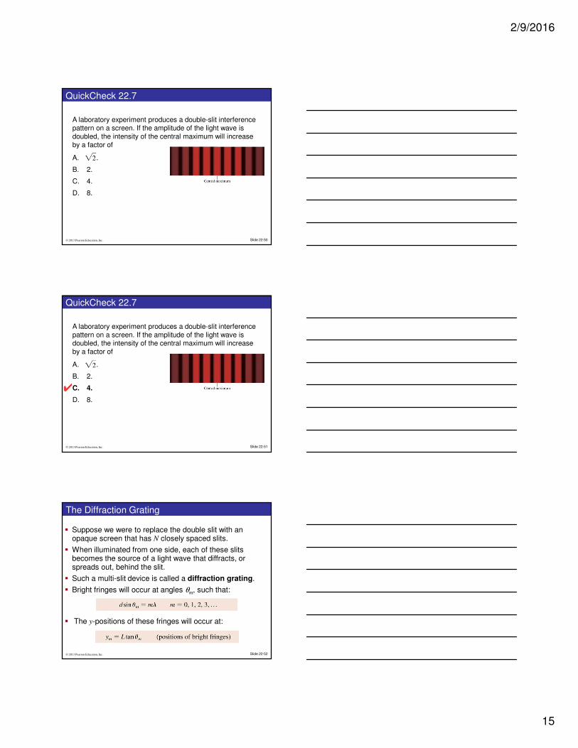
QuickCheck 22.7
A laboratory experiment produces a double-slit interference pattern on a screen. If the amplitude of the light wave is doubled, the intensity of the central maximum will increase by a factor of
A. .
B. 2.
C. 4.
D. 8.
Slide 22-50
© 2013 Pearson Education, Inc.
QuickCheck 22.7
A laboratory experiment produces a double-slit interference pattern on a screen. If the amplitude of the light wave is doubled, the intensity of the central maximum will increase by a factor of
A. .
B. 2.
C. 4.
D. 8.
Slide 22-51
© 2013 Pearson Education, Inc.
The Diffraction Grating
� Suppose we were to replace the double slit with an opaque screen that has N closely spaced slits.
� When illuminated from one side, each of these slits becomes the source of a light wave that diffracts, or spreads out, behind the slit.
� Such a multi-slit device is called a diffraction grating.
� Bright fringes will occur at angles θm, such that:
� The y-positions of these fringes will occur at:
Slide 22-52
2/9/2016
16
© 2013 Pearson Education, Inc.
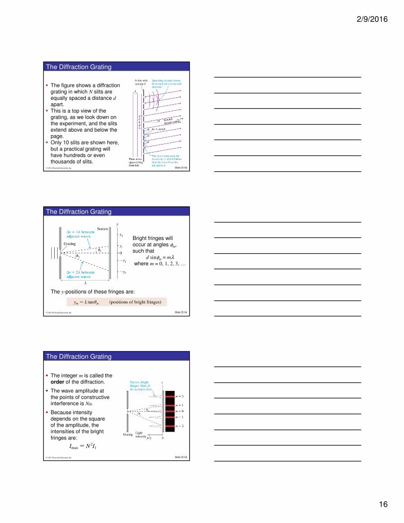
The Diffraction Grating
� The figure shows a diffraction grating in which N slits are equally spaced a distance dapart.
� This is a top view of the grating, as we look down on the experiment, and the slits extend above and below the page.
� Only 10 slits are shown here,
but a practical grating will have hundreds or even thousands of slits.
Slide 22-53
© 2013 Pearson Education, Inc.
The Diffraction Grating
Bright fringes will occur at angles φm,
such thatd sinφm = mλ
where m = 0, 1, 2, 3, …
The y-positions of these fringes are:
Slide 22-54
© 2013 Pearson Education, Inc.
The Diffraction Grating
� The integer m is called the order of the diffraction.
� The wave amplitude at
the points of constructive interference is Na.
� Because intensity depends on the square of the amplitude, the intensities of the bright
fringes are:
Slide 22-55

2/9/2016
17
© 2013 Pearson Education, Inc.
The Diffraction Grating
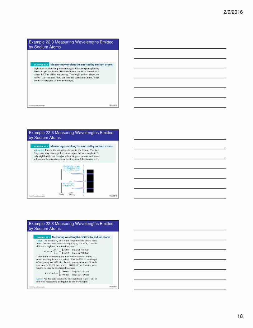
� Diffraction gratings are used for measuring the wavelengths of light.
� If the incident light consists of two slightly different wavelengths, each wavelength will be diffracted at a slightly different angle.
Slide 22-56
© 2013 Pearson Education, Inc.
QuickCheck 22.8
In a laboratory experiment, a diffraction grating produces an interference pattern on a screen. If the number of slits in the grating is increased, with everything else (including the slit spacing) the same, then
A. The fringes stay the same brightness and get closer together.
B. The fringes stay the same brightness and get farther apart.
C. The fringes stay in the same positions but get brighter and narrower.
D. The fringes stay in the same positions but get dimmer and wider.
E. The fringes get brighter, narrower, and closer together.
Slide 22-57
© 2013 Pearson Education, Inc.
QuickCheck 22.8
In a laboratory experiment, a diffraction grating produces an interference pattern on a screen. If the number of slits in the grating is increased, with everything else (including the slit spacing) the same, then
A. The fringes stay the same brightness and get closer together.
B. The fringes stay the same brightness and get farther apart.
C. The fringes stay in the same positions but get brighter and narrower.
D. The fringes stay in the same positions but get dimmer and wider.
E. The fringes get brighter, narrower, and closer together.
Slide 22-58
2/9/2016
18
© 2013 Pearson Education, Inc.
Example 22.3 Measuring Wavelengths Emitted
by Sodium Atoms
Slide 22-59
© 2013 Pearson Education, Inc.
Example 22.3 Measuring Wavelengths Emitted
by Sodium Atoms
Slide 22-60
© 2013 Pearson Education, Inc.
Example 22.3 Measuring Wavelengths Emitted
by Sodium Atoms
Slide 22-61

2/9/2016
19
© 2013 Pearson Education, Inc.
Reflection Gratings
� In practice, most diffraction gratings are manufactured as reflection gratings.
� The interference pattern
is exactly the same as the interference pattern of light transmitted through N parallel slits.
Slide 22-62
© 2013 Pearson Education, Inc.
Reflection Gratings
� Naturally occurring reflection gratings are responsible for some forms of color in nature.
� A peacock feather consists of nearly parallel rods of melanin, which act as a reflection grating.
Slide 22-63
© 2013 Pearson Education, Inc.
Single-Slit Diffraction
� Diffraction through a tall, narrow slit is known as single-slit diffraction.
� A viewing screen is placed distance L
behind the slit of width a, and we will assume that L >> a.
Slide 22-64
2/9/2016
20
© 2013 Pearson Education, Inc.
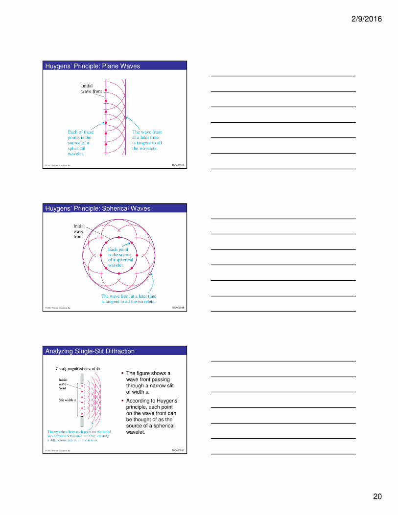
Huygens’ Principle: Plane Waves
Slide 22-65
© 2013 Pearson Education, Inc.
Huygens’ Principle: Spherical Waves
Slide 22-66
© 2013 Pearson Education, Inc.
Analyzing Single-Slit Diffraction
� The figure shows a wave front passing through a narrow slit of width a.
� According to Huygens’ principle, each point on the wave front can be thought of as the source of a spherical
wavelet.
Slide 22-67
2/9/2016
21
© 2013 Pearson Education, Inc.
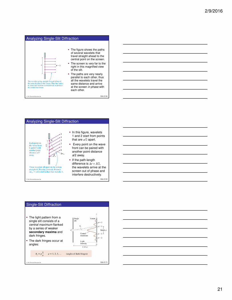
Analyzing Single-Slit Diffraction
� The figure shows the paths of several wavelets that travel straight ahead to the central point on the screen.
� The screen is very far to the right in this magnified view of the slit.
� The paths are very nearly parallel to each other, thus all the wavelets travel the same distance and arrive at the screen in phase with each other.
Slide 22-68
© 2013 Pearson Education, Inc.
Analyzing Single-Slit Diffraction
� In this figure, wavelets 1 and 2 start from points that are a/2 apart.
� Every point on the wave front can be paired with another point distance a/2 away.
� If the path-length difference is ∆r = λ/2,
the wavelets arrive at the screen out of phase and interfere destructively.
Slide 22-69
© 2013 Pearson Education, Inc.
Single-Slit Diffraction
� The light pattern from a single slit consists of a central maximum flanked by a series of weaker
secondary maxima and dark fringes.
� The dark fringes occur at angles:
Slide 22-70
2/9/2016
22
© 2013 Pearson Education, Inc.
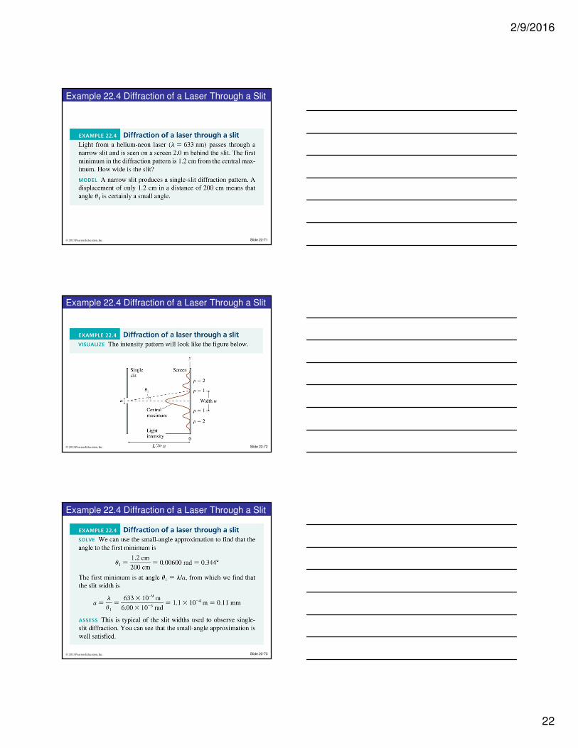
Example 22.4 Diffraction of a Laser Through a Slit
Slide 22-71
© 2013 Pearson Education, Inc.
Example 22.4 Diffraction of a Laser Through a Slit
Slide 22-72
© 2013 Pearson Education, Inc.
Example 22.4 Diffraction of a Laser Through a Slit
Slide 22-73
2/9/2016
23
© 2013 Pearson Education, Inc.
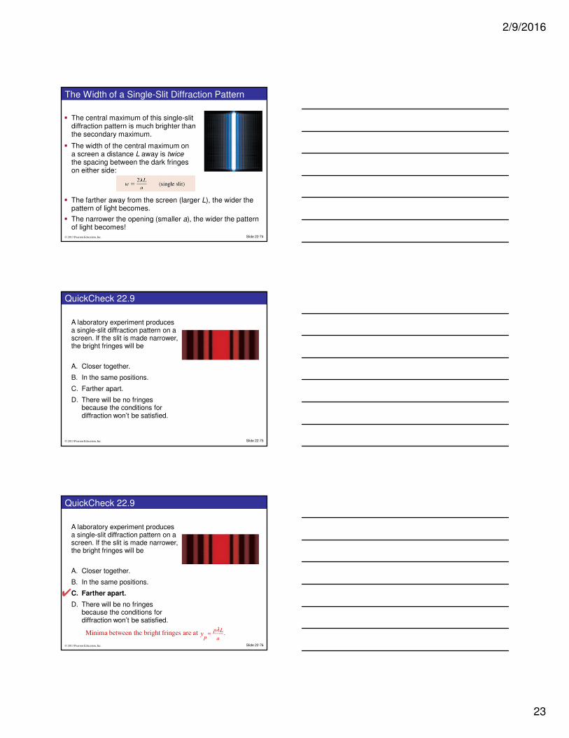
The Width of a Single-Slit Diffraction Pattern
� The central maximum of this single-slit diffraction pattern is much brighter than the secondary maximum.
� The width of the central maximum on a screen a distance L away is twice the spacing between the dark fringes on either side:
� The farther away from the screen (larger L), the wider the pattern of light becomes.
� The narrower the opening (smaller a), the wider the pattern of light becomes!
Slide 22-74
© 2013 Pearson Education, Inc.
QuickCheck 22.9
A laboratory experiment produces a single-slit diffraction pattern on a screen. If the slit is made narrower, the bright fringes will be
A. Closer together.
B. In the same positions.
C. Farther apart.
D. There will be no fringes because the conditions for diffraction won’t be satisfied.
Slide 22-75
© 2013 Pearson Education, Inc.
QuickCheck 22.9
A laboratory experiment produces a single-slit diffraction pattern on a screen. If the slit is made narrower, the bright fringes will be
A. Closer together.
B. In the same positions.
C. Farther apart.
D. There will be no fringes because the conditions for diffraction won’t be satisfied.
Minima between the bright fringes are at . yp
=pλL
aSlide 22-76
2/9/2016
24
© 2013 Pearson Education, Inc.
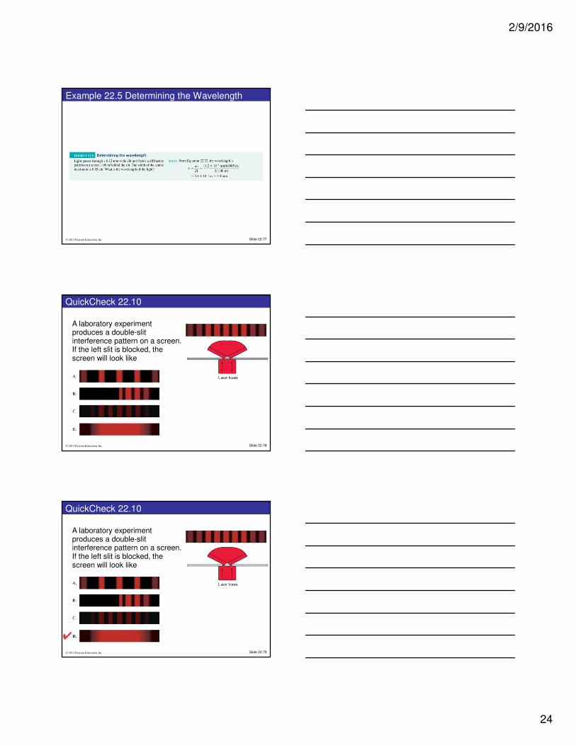
Example 22.5 Determining the Wavelength
Slide 22-77
© 2013 Pearson Education, Inc.
A laboratory experiment produces a double-slit interference pattern on a screen. If the left slit is blocked, the screen will look like
QuickCheck 22.10
Slide 22-78
© 2013 Pearson Education, Inc.
A laboratory experiment produces a double-slit interference pattern on a screen. If the left slit is blocked, the screen will look like
QuickCheck 22.10
Slide 22-79
2/9/2016
25
© 2013 Pearson Education, Inc.
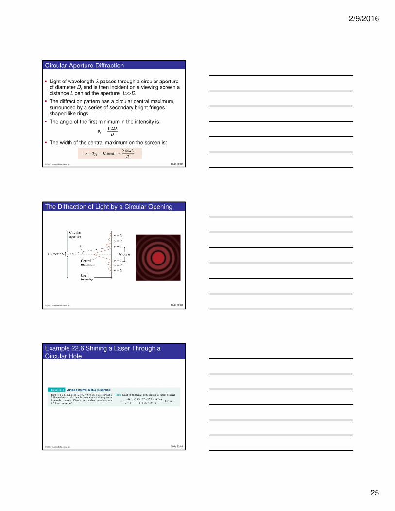
Circular-Aperture Diffraction
� Light of wavelength λ passes through a circular aperture of diameter D, and is then incident on a viewing screen a distance L behind the aperture, L>>D.
� The diffraction pattern has a circular central maximum, surrounded by a series of secondary bright fringes shaped like rings.
� The angle of the first minimum in the intensity is:
� The width of the central maximum on the screen is:
Slide 22-80
© 2013 Pearson Education, Inc.
The Diffraction of Light by a Circular Opening
Slide 22-81
© 2013 Pearson Education, Inc.
Example 22.6 Shining a Laser Through a
Circular Hole
Slide 22-82
2/9/2016
26
© 2013 Pearson Education, Inc.
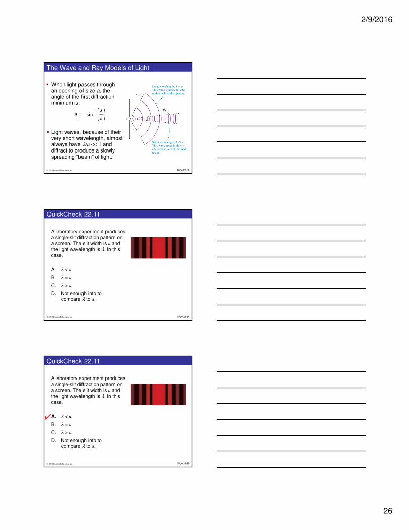
The Wave and Ray Models of Light
� When light passes through an opening of size a, the angle of the first diffraction minimum is:
� Light waves, because of their very short wavelength, almost always have λ/a << 1 and diffract to produce a slowly spreading “beam” of light.
Slide 22-83
© 2013 Pearson Education, Inc.
QuickCheck 22.11
A laboratory experiment produces a single-slit diffraction pattern on a screen. The slit width is a and the light wavelength is λ. In this case,
A. λ < a.
B. λ = a.
C. λ > a.
D. Not enough info to compare λ to a.
Slide 22-84
© 2013 Pearson Education, Inc.
QuickCheck 22.11
A laboratory experiment produces a single-slit diffraction pattern on a screen. The slit width is a and the light wavelength is λ. In this case,
A. λ < a.
B. λ = a.
C. λ > a.
D. Not enough info to compare λ to a.
Slide 22-85
2/9/2016
27
© 2013 Pearson Education, Inc.
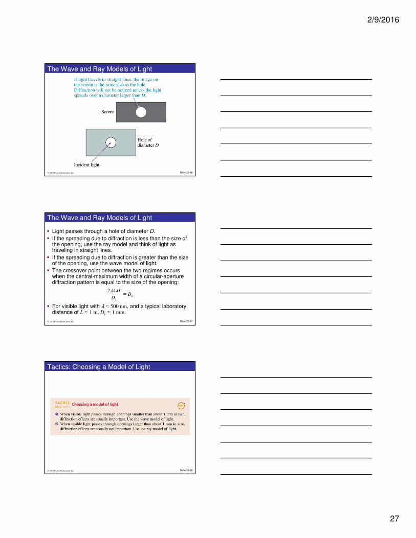
The Wave and Ray Models of Light
Slide 22-86
© 2013 Pearson Education, Inc.
The Wave and Ray Models of Light
� Light passes through a hole of diameter D.
� If the spreading due to diffraction is less than the size of the opening, use the ray model and think of light as traveling in straight lines.
� If the spreading due to diffraction is greater than the size of the opening, use the wave model of light.
� The crossover point between the two regimes occurs when the central-maximum width of a circular-aperture diffraction pattern is equal to the size of the opening:
� For visible light with λ ≈ 500 nm, and a typical laboratory distance of L ≈ 1 m, Dc ≈ 1 mm.
Slide 22-87
© 2013 Pearson Education, Inc.
Tactics: Choosing a Model of Light
Slide 22-88
2/9/2016
28
© 2013 Pearson Education, Inc.
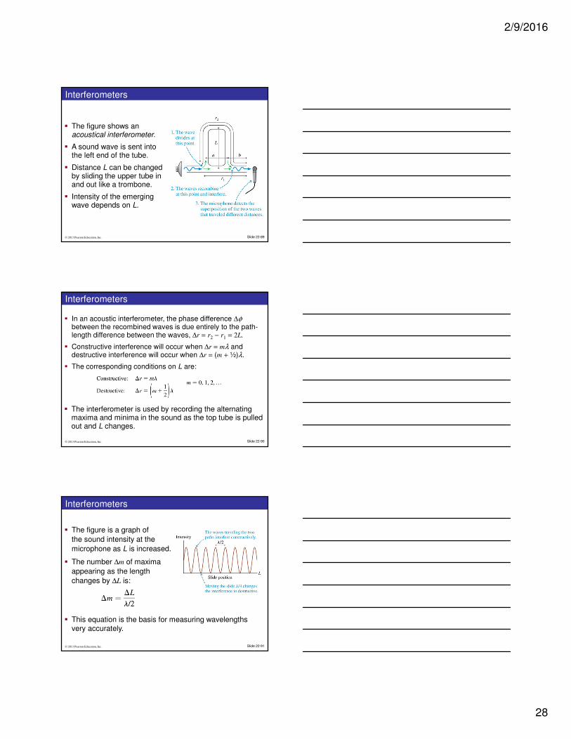
Interferometers
� The figure shows an acoustical interferometer.
� A sound wave is sent into the left end of the tube.
� Distance L can be changed by sliding the upper tube in and out like a trombone.
� Intensity of the emerging wave depends on L.
Slide 22-89
© 2013 Pearson Education, Inc.
Interferometers
� In an acoustic interferometer, the phase difference ∆φbetween the recombined waves is due entirely to the path-length difference between the waves, ∆r = r2 − r1 = 2L.
� Constructive interference will occur when ∆r = mλ and destructive interference will occur when ∆r = (m + ½)λ.
� The corresponding conditions on L are:
� The interferometer is used by recording the alternating maxima and minima in the sound as the top tube is pulled out and L changes.
Slide 22-90
© 2013 Pearson Education, Inc.
Interferometers
� The figure is a graph of
the sound intensity at the
microphone as L is increased.
� The number ∆m of maxima
appearing as the length
changes by ∆L is:
� This equation is the basis for measuring wavelengths very accurately.
Slide 22-91
2/9/2016
29
© 2013 Pearson Education, Inc.
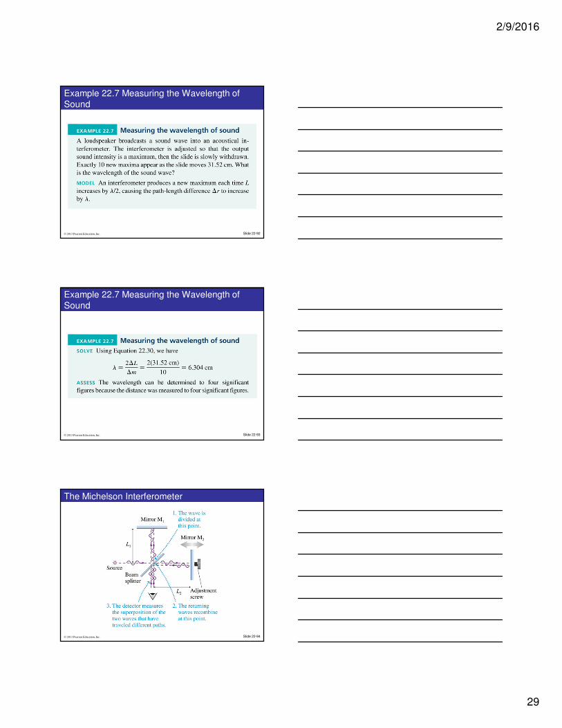
Example 22.7 Measuring the Wavelength of
Sound
Slide 22-92
© 2013 Pearson Education, Inc.
Example 22.7 Measuring the Wavelength of
Sound
Slide 22-93
© 2013 Pearson Education, Inc.
The Michelson Interferometer
Slide 22-94
2/9/2016
30
© 2013 Pearson Education, Inc.
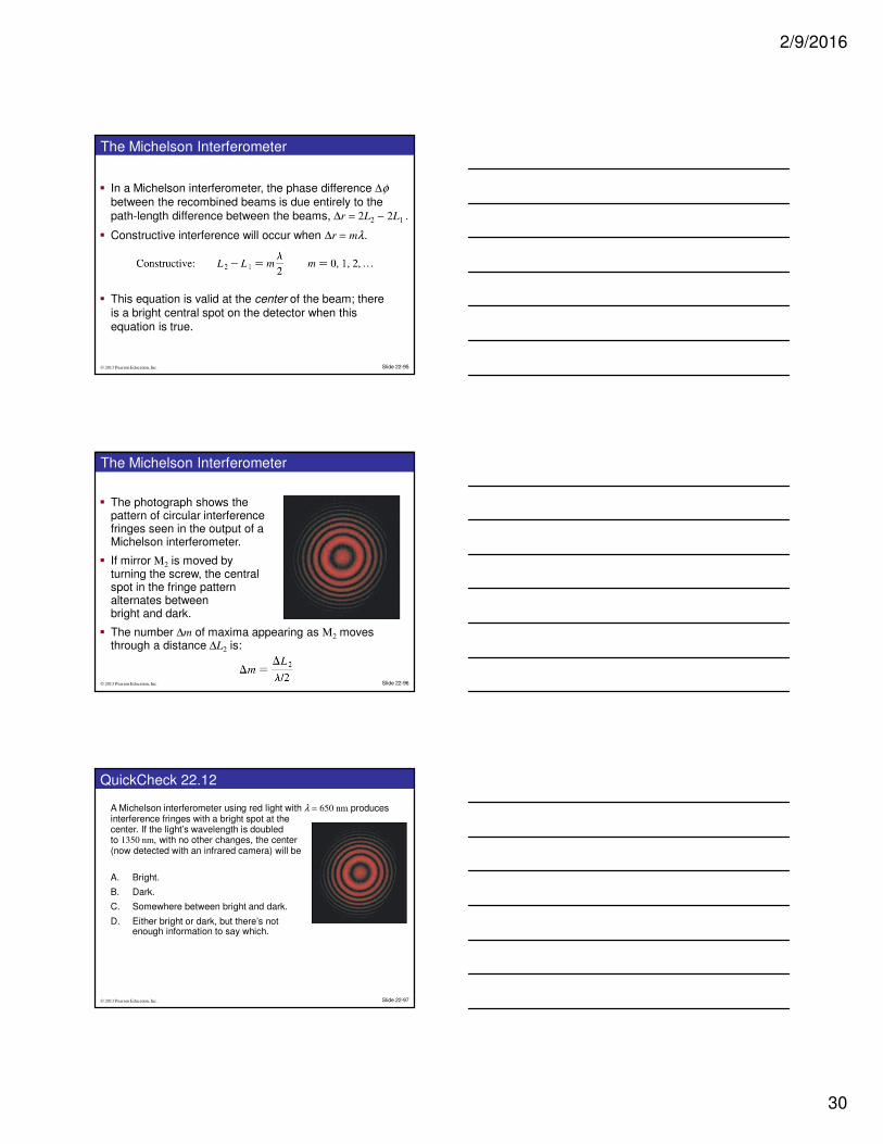
The Michelson Interferometer
� In a Michelson interferometer, the phase difference ∆φbetween the recombined beams is due entirely to the path-length difference between the beams, ∆r = 2L2 − 2L1 .
� Constructive interference will occur when ∆r = mλ.
� This equation is valid at the center of the beam; there is a bright central spot on the detector when this equation is true.
Slide 22-95
© 2013 Pearson Education, Inc.
The Michelson Interferometer
� The photograph shows the pattern of circular interference fringes seen in the output of a Michelson interferometer.
� If mirror M2 is moved by turning the screw, the central spot in the fringe pattern alternates between bright and dark.
� The number ∆m of maxima appearing as M2 moves through a distance ∆L2 is:
Slide 22-96
© 2013 Pearson Education, Inc.
QuickCheck 22.12
A Michelson interferometer using red light with λ = 650 nm produces interference fringes with a bright spot at the center. If the light’s wavelength is doubled to 1350 nm, with no other changes, the center (now detected with an infrared camera) will be
A. Bright.
B. Dark.
C. Somewhere between bright and dark.
D. Either bright or dark, but there’s not enough information to say which.
Slide 22-97
2/9/2016
31
© 2013 Pearson Education, Inc.
QuickCheck 22.12
A Michelson interferometer using red light with λ = 650 nm produces interference fringes with a bright spot at the center. If the light’s wavelength is doubled to 1350 nm, with no other changes, the center (now detected with an infrared camera) will be
A. Bright.
B. Dark.
C. Somewhere between bright and dark.
D. Either bright or dark, but there’s not enough information to say which.
∆r = 2∆L = mλ
If λ is doubled, m must be halved to keep ∆L constant.
If m is even, m/2 is still an integer and the interference is still constructive.
If m is odd, m/2 is a half-integer and the interference is destructive.
Slide 22-98
© 2013 Pearson Education, Inc.
Example 22.8 Measuring the Wavelength of Light
Slide 22-99
© 2013 Pearson Education, Inc.
Example 22.8 Measuring the Wavelength of Light
Slide 22-100
2/9/2016
32
© 2013 Pearson Education, Inc.
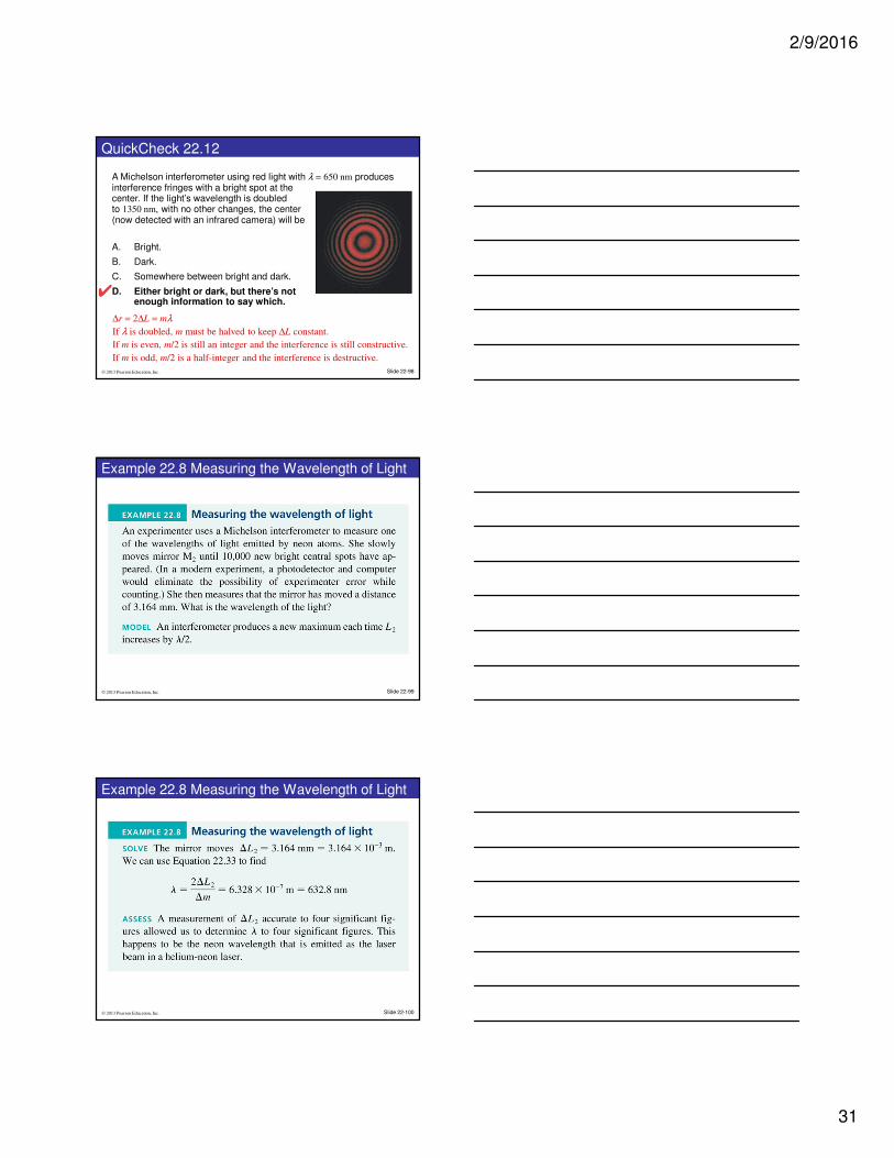
Holography
The figure shows shows how a hologram is recorded.
Slide 22-101
© 2013 Pearson Education, Inc.
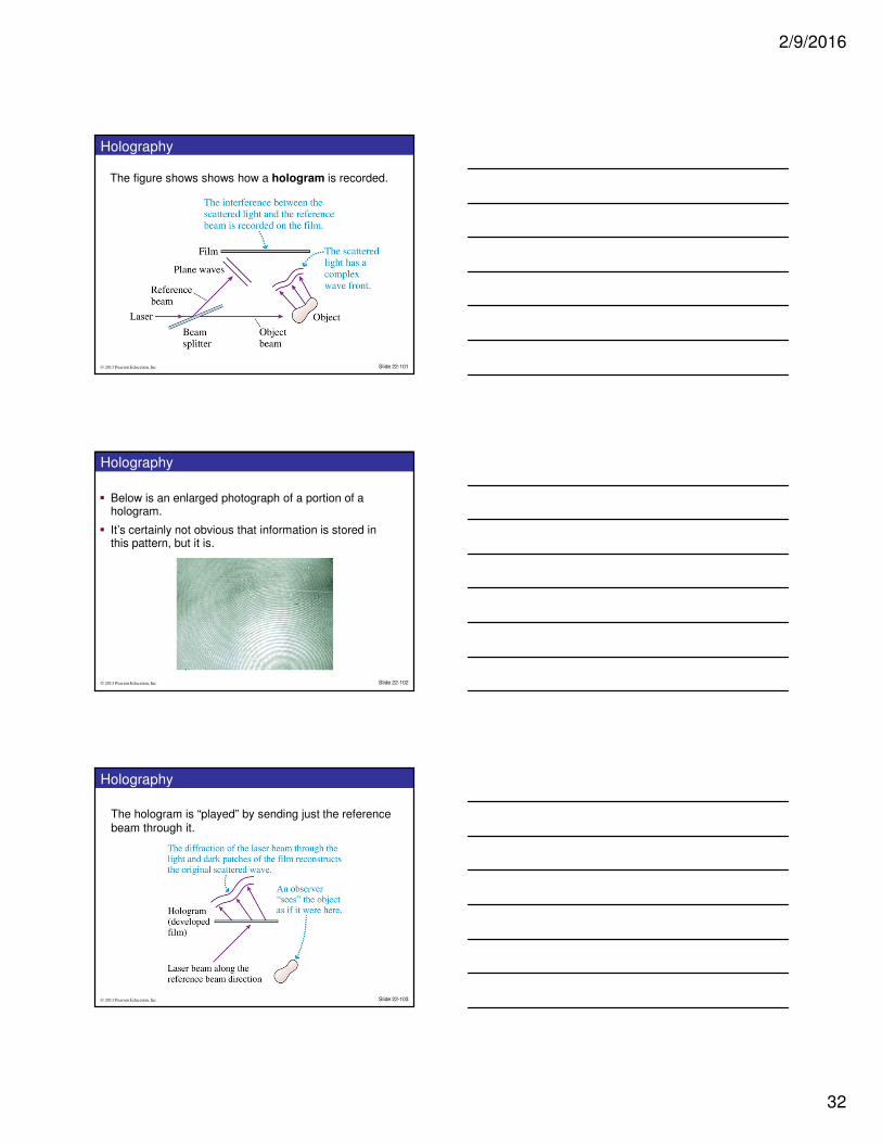
Holography
� Below is an enlarged photograph of a portion of a hologram.
� It’s certainly not obvious that information is stored in this pattern, but it is.
Slide 22-102
© 2013 Pearson Education, Inc.
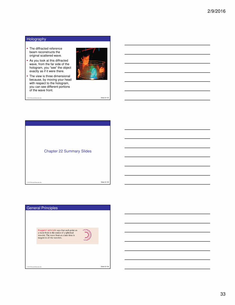
Holography
The hologram is “played” by sending just the reference beam through it.
Slide 22-103
2/9/2016
33
© 2013 Pearson Education, Inc.
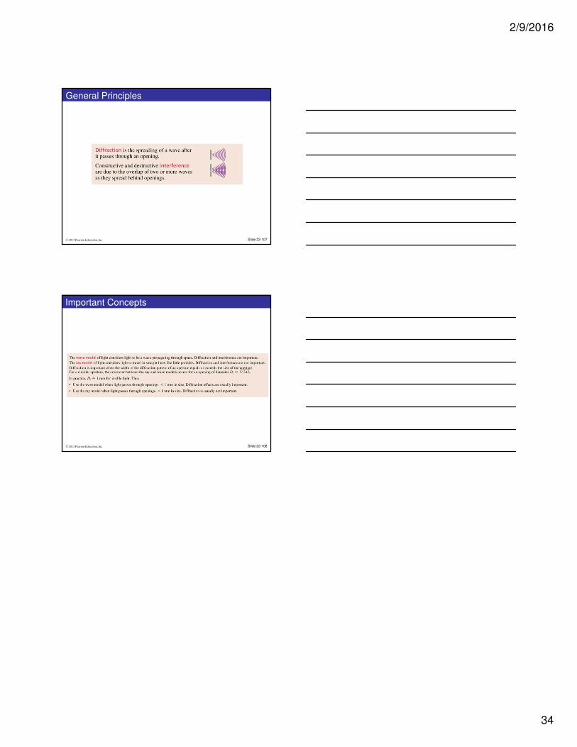
Holography
� The diffracted reference beam reconstructs the original scattered wave.
� As you look at this diffracted wave, from the far side of the hologram, you “see” the object exactly as if it were there.
� The view is three dimensional because, by moving your head with respect to the hologram, you can see different portions of the wave front.
Slide 22-104
© 2013 Pearson Education, Inc.
Chapter 22 Summary Slides
Slide 22-105
© 2013 Pearson Education, Inc.
General Principles
Slide 22-106
2/9/2016
34
© 2013 Pearson Education, Inc.
General Principles
Slide 22-107
© 2013 Pearson Education, Inc.
Important Concepts
Slide 22-108