Embed Size (px)
Citation preview
CHAPTER
19
NONLINEAR OPTICS
19.1
19.2
19.3
*19.4
*19.5
*19.6
*19.7
19.8
NONLINEAR OPTICAL MEDIA
SECOND-ORDER NONLINEAR OPTICS
A. Second-Harmonic Generation and Rectification
B. The Electra-Optic Effect
C. Three-Wave Mixing
THIRD-ORDER NONLINEAR OPTICS
A. Third-Harmonic Generation and Self-Phase Modulation
B. Four-Wave Mixing
C. Optical Phase Conjugation
COUPLED-WAVE THEORY OF THREE-WAVE MIXING
A. Second-Harmonic Generation
B. Frequency Conversion
C. Parametric Amplification and Oscillation
COUPLED-WAVE THEORY OF FOUR-WAVE MIXING
ANISOTROPIC NONLINEAR MEDIA
DISPERSIVE NONLINEAR MEDIA
OPTICAL SOLITONS
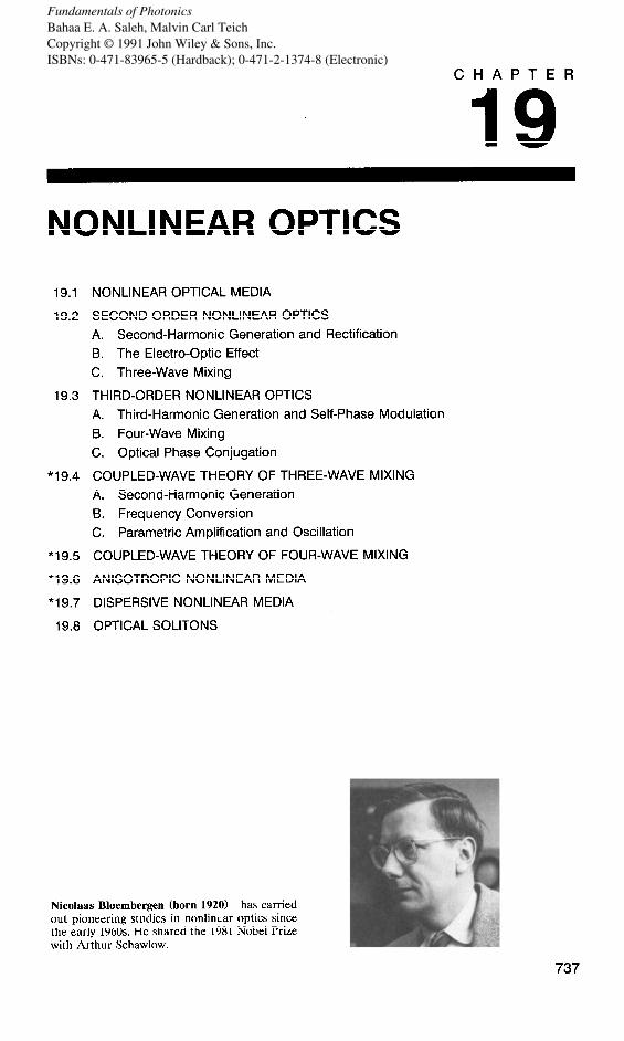
Nicolaas Bloembergen (born 1920) has carried out pioneering studies in nonlinbar optics since the early 1960s. He shared the 1981 Nobel Prize with Arthur Schawlow.
737
Fundamentals of PhotonicsBahaa E. A. Saleh, Malvin Carl TeichCopyright © 1991 John Wiley & Sons, Inc.ISBNs: 0-471-83965-5 (Hardback); 0-471-2-1374-8 (Electronic)
Throughout the long history of optics, and indeed until relatively recently, it was thought that all optical media were linear. The assumption of linearity of the optical medium has far-reaching consequences:
n The optical properties, such as the are independent of light intensity.
refractive index and the absorption coefficient,
n The principle of superposition, a fundamental tenet of classical optics (as de- scribed in Sec. 2.11, holds.
. The frequency of light cannot be altered by its passage through the medium.
. Light cannot interact with light; two beams of light in the same region of a linear optical medium can have no effect on each other. Thus light cannot control light.
The invention of the laser in 1960 enabled us to examine the behavior of light in optical materials at higher intensities than previously possible. Many of the experi- ments carried out made it clear that optical media do in fact exhibit nonlinear behavior, as exemplified by the following observations:
9 The refractive index, and consequently the speed of light in an optical medium, does change with the light intensity.
n The principle of superposition is violated. 9 Light can alter its frequency as it passes through a nonlinear optical material
(e.g., from red to blue!). n Light can control light; photons do interact.
The field of nonlinear optics comprises many fascinating phenomena. Linearity or nonlinearity is a property of the medium through which light travels,
rather than a property of the light itself. Nonlinear behavior is not exhibited when light travels in free space. Light interacts with light via the medium. The presence of an optical field modifies the properties of the medium which, in turn, modify another optical field or even the original field itself.
It was pointed out in Sec. 5.2 that the properties of a dielectric medium through which an electromagnetic (optical) wave propagates are completely described by the relation between the polarization density vector P(r, t) and the electric-field vector 8(r, t). It was suggested that .P(r, t) could be regarded as the output of a system whose input was &Y(r, t). The mathematical relation between the vector functions P(r, t) and 8’(r) t) defines the system and is governed by the characteristics of the medium. The medium is said to be nonlinear if this relation is nonlinear.
In Sec. 5.2, dielectric media were further classified with respect to their homogene- ity, isotropy, and dispersiveness. To focus on the principal effect of interest in this chapter-nonlinearity- the medium is initially assumed to be homogeneous, isotropic, and nondispersive. Sections 19.6 and 19.7 provide brief discussions of anisotropic and dispersive nonlinear optical media.
738

NONLINEAR OPTICAL MEDIA 739
The theory of nonlinear optics and its applications is presented at two levels. A simplified approach is provided in Sets. 19.1 to 19.3. This is followed by a more detailed analysis of the same phenomena in Sets. 19.4 and 19.5.
Light propagation in media characterized by a second-order (quadratic) nonlinear relation between ZP and Z is described in Sets. 19.2 and 19.4. Applications include the frequency doubling of a monochromatic wave (second-harmonic generation), the mixing of two monochromatic waves to generate a third wave whose frequency is the sum or difference of the frequencies of the original waves (frequency conversion), the use of two monochromatic waves to amplify a third wave (parametric amplification), and the addition of feedback to a parametric amplifier to create an oscillator (parametric oscillation). Wave propagation in a medium with a third-order P-8 relation is discussed in Sets. 19.3 and 19.5. Applications include third-harmonic generation, self-phase modulation, self-focusing, four-wave mixing, optical ampli.cation , and optical phase conjugation .
Optical solitons are discussed in Sec. 19.8. These are optical pulses that propagate in a nonlinear dispersive medium without changing their shape. Changes in the pulse profile caused by the dispersive and nonlinear effects just compensate each other, so that the pulse shape is maintained for long propagation distances. Optical bistability is yet another nonlinear optical effect that has applications in photonic switching; its discussion is relegated to Chap. 21.
19.1 NONLINEAR OPTICAL MEDIA
A linear dielectric medium is characterized by a linear relation between the polariza- tion density and the electric field, 9 = e0x8:, where E, is the permittivity of free space and x is the electric susceptibility of the medium (see Sec. 5.2A). A nonlinear dielectric medium, on the other hand, is characterized by a nonlinear relation between 9 and Z?, as illustrated in Fig. 19.1-1.
The nonlinearity may be of microscopic or macroscopic origin. The polarization density 9 = NP is a product of the individual dipole moment P, which is induced by the applied electric field 8, and the number density of dipole moments N. The nonlinear behavior may have its origin in either p or in N.
The relation between P and 8 is linear when 8 is small, but becomes nonlinear as 8 acquires values comparable with interatomic electric fields (typically, lo5 to lo* V/m). This may be explained in terms of the simple Lorentz model in which the dipole moment is /t = -ex, where x is the displacement of a mass with charge -e to which an electric force -eG?? is applied (see Sec. 5.50 If the restraining elastic force is
(a) lb)
Figure 19.1-1 The 947 relation for (a) a linear dielectric medium, and (b) a nonlinear medium.

740 NONLINEAR OPTICS
proportional to the displacement (i.e., if Hooke’s law is satisfied), the equilibrium displacement x is proportional to g; 9 is then proportional to g:, and the medium is linear. However, if the restraining force is a nonlinear function of the displacement, the equilibrium displacement x and the polarization density 9 are nonlinear functions of 8 and, consequently, the medium is nonlinear. The time dynamics of an anharmonic oscillator model describing a dielectric medium with these features is discussed in Sec. 19.7.
Another possible origin of the nonlinear response of an optical material to light is the dependence of the number density N on the optical field. An example is a laser medium for which the number of atoms occupying the energy levels involved in the absorption and emission of light are dependent on the intensity of the light itself (see Sec. 13.3).
Since externally applied optical electric fields are typically small in comparison with characteristic interatomic or crystalline fields, even when focused laser light is used, the nonlinearity is usually weak. The relation between 9 and 8 is then approximately linear for small 8, deviating only slightly from linearity as Z increases (see Fig. 19.1-1). Under these circumstances, it is possible to expand the function that relates LP to .8 in a Taylor’s series about &? = 0,
and to use only few terms. The coefficients a,, a2, and a3 are the first, second, and third derivatives of ~8 with respect to 8 at Z? = 0. These coefficients are characteristic constants of the medium. The first term, which is linear, dominates at small 8. Clearly, al = E~X, where x is the linear susceptibility, which is related to the dielectric constant and the refractive index by n2 = E/E, = 1 + x. The second term represents a quadratic or second-order nonlinearity, the third term represents a third-order nonlinearity, and so on.
It is customary to write (19.1-l) in the form?
9 = E x8 + 2dc3Y2 + 4x’3’83 + * * * 0 , (19.1-2)
where d = ia2 and x (3) = $a3 are coefficients describing the second- and third-order nonlinear effects, respectively.
Equation (19.1-2) provides the basic description for a nonlinear optical medium. Anisotropy, dispersion, and inhomogeneity have been ignored both for simplicity and to enable us to focus on the basic nonlinear effect without the added algebraic complications brought about by these auxiliary effects. Sections 19.6 and 19.7 are devoted to anisotropic and dispersive nonlinear media.
In centrosymmetric media (these are media with inversion symmetry, so that the properties of the medium are not altered by the transformation r + -r), the Y-8 function must have odd symmetry, so that the reversal of ZY results in the reversal of 9 without any other change. The second-order nonlinear coefficient a( must then vanish, and the lowest order nonlinearity is of third order.
Typical values of the second-order nonlinear coefficient d for dielectric crystals, semiconductors, and organic materials used in photonics applications lie in the range
‘This nomenclature is used in a number of books, such as A. Yariv, Quantum Electronics, Wiley, New York, 3rd ed. 1989. An alternative relation, LP = E&Z + xC2)g2 + xC3?!F3), is used in other books, e.g., Y. R. Shen, The Principles of Nonlinear Optics, Wiley, New York, 1984.
NONLINEAR OPTICAL MEDIA 741
d = lo-% to lO-‘l (MKS units, A-s/V2). Typical values of the third-order nonlinear coefficient x c3) for glasses crystals, semiconductors, semiconductor-doped glasses, and organic materials of inter&t in photonics are xc3) = 1O-34 to 1O-29 (MKS units).
EXERC/SE 19.1-I
Intensity of Light Necessary to Exhibit Nonlinear Effects
(a) Determine the intensity of light (in W/cm*) at which the ratio of the second term to the first term in (19.1-2) is 1% in an ADP (NH,H2P04) crystal for which n = 1.5 and d = 6.8 x 1Owz (MKS units) at A, = 1.06 pm.
(b) Determine the intensity of light at which the third term in (19.1-2) is 1% of the first term in carbon disulfide (CS,) for which n = 1.6, d = 0, and xc3) = 4.4 x 10e3* (MKS units) at A, = 694 nm.
Note: The intensity of light is I = (a2)/q, where q = q,/n is the impedance of the medium and q0 = (~JE,)~/* = 377 R is the impedance of free space.
The Nonlinear Wave Equation The propagation of light in a nonlinear medium is governed by the wave equation (5.2-19), which was derived from Maxwell’s equations for an arbitrary homogeneous dielectric medium,
2 2
v2,g- c!? ;&$ cz dt2 (19.1-3)
It is convenient to write Z@ as a sum of linear and nonlinear parts,
9 = E&T +PNL, (19.1-4)
9 NL= 2&F2 + 4x’3’83 + *** . (19.1-5)
Using (19.1-4) and the relations n2 = 1 + ,y, c, = l/(p,~,)~/~, and c = c,/n, (19.1-3) may be written as
1 d2kF v2(gL--=+Q
c2 dt2
d2YNL s;"= --pop at2 -
(19.1-6)
(19.1-7) Wave Equation in
a Nonlinear Medium
It is useful to regard (19.1-6) as a wave equation in which the term 9 = -,x, d29,,/dt2 acts as a source radiating in a linear medium of refractive index n. Because PNL (and therefo re Sa) is a nonlinear function of 8, (19.1-6) is a nonlinear partial differential equation in 8. This is the basic equation that underlies the theory of nonlinear optics.
There are two approximate approaches to solving the nonlinear wave equation. The first is an iterative approach known as the Born approximation. This approximation

742 NONLINEAR OPTICS
underlies the simplified introduction to nonlinear optics presented in Sets. 19.2 and 19.3. The second approach is a coupled-wave theory in which the nonlinear wave equation is used to derive linear coupled partial differential equations that govern the interacting waves. This is the basis of the more advanced study of wave interactions in nonlinear media, which is presented in Sets. 19.4 and 19.5.
Scattering Theory of Nonlinear Optics: The Born Approximation The radiation source Y in (19.1-6) is a function of the field 8 that it, itself, radiates. To emphasize this point we write ~7 = P(Z) and illustrate the process by a simple diagram:
Suppose that an optical field go is incident on a nonlinear medium confined to some volume (see Fig. 19.1-2). This field creates a radiation source Y(Zc) that radiates an optical field Zr. The corresponding radiation source Y(Ei) radiates a field EZ, and so on. This process suggests an iterative solution, the first step of which is known as the first Born approximation. The second Born approximation carries the process an additional iteration, and so on.
The first Born approximation is adequate when the light intensity is sufficiently weak so that the nonlinearity is small. In this approximation, light propagation through the nonlinear medium is regarded as a scattering process in which the incident field is scattered by the medium. The scattered light is determined from the incident light in two steps:
n The incident field go is used to determine the nonlinear polarization density YNL, from which the radiation source Y(&YJ is determined.
n The radiated (scattered) field Z?r is determined from the radiation source by adding the spherical waves associated with the different source points (as in the theory of diffraction discussed in Sec. 4.3).
In many cases the amount of scattered light is very small, so that the depletion of the incident light is indeed negligible and the first Born approximation is adequate. Sections 19.2 and 19.3 are based on the first Born approximation. An initial field gO containing one or several monochromatic waves of different frequencies is assumed,
Incident Radiated light 8
0 : ‘::’ : A....
light X1
. . ‘_ ., .. _. ,. : :: ,,:
. . :
Radiation source
medium
Figure 19.1-2 The first Born approximation. An incident optical field go creates a source 9(gO), which radiates an optical field &YI.

SECOND-ORDER NONLINEAR OPTICS 743
The corresponding nonlinear polarization gNL is then determined using (19.1-5) and the source function Y(gc) is evaluated using (19.1-7). Since P(gO) is a nonlinear function, new frequencies are created. The source therefore emits an optical field g1 with frequencies not present in the original wave go. This leads to numerous interest- ing phenomena that have been utilized to make useful nonlinear-optics devices.
19.2 SECOND-ORDER NONLINEAR OPTICS
In this section we examine the optical properties of a nonlinear medium in which nonlinearities of order higher than the second are negligible, so that
(19.2-1)
We consider an electric field 8’ comprising one or two harmonic components and determine the spectral components of gNL. In accordance with the first Born approxi- mation, the radiation source Y contains the same spectral components as PNL, and so, therefore, does the emitted (scattered) field.
A. Second-Harmonic Generation and Rectification
Consider the response of this nonlinear medium to a harmonic electric field frequency 0 (wavelength A, = 2rrc,/w) and complex amplitude E(U),
of angular
k?(t) = Re{E(w) exp(jwt)}. (19.2-2)
The corresponding nonlinear polarization density YNL is obtained by substituting (19.2-2) into (19.2-l),
gNL( t> = PNL(0) + Re{ &&d exp(.%t)}, (19.2-3)
P&O) =dE(o)E*(o) (19.2-4)
P,,(2w) =dE(o)E(w). (19.2-5)
This process is illustrated graphically in Fig. 19.2-1.
dc second-harmonic
Figure 19.2-1 A sinusoidal electric field of angular frequency w in a second-order nonlinear optical medium creates (dc) component.
a polarization with a component at 2w (second-harmonic) and a steady

744 NONLINEAR OPTICS
Second-Harmonic Generation The source Y(t) = -pO J2p,/at2 corresponding to (19.2-3) has a component at frequency 20 and complex amplitude S(20) = 4p,w2 dE(w)E(o), which radiates an optical field at frequency 2w (wavelength A,/2). Thus the scattered optical field has a component at the second harmonic of the incident optical field. Since the amplitude of the emitted second-harmonic light is proportional to S(2w), its intensity is proportional to lS(20)1~ a o4 d2r2, where I = IE(w)12/277 is the intensity of the incident wave. The intensity of the second-harmonic wave is therefore proportional to d2, to l/h:, and to 12. Consequently, the efficiency of second-harmonic generation is proportional to I = P/A, where P is the incident power and A is the cross-sectional area. It is therefore essential that the incident wave have the largest possible power and be focused to the smallest possible area to produce strong second-harmonic radiation. Pulsed lasers are convenient in this respect since they deliver large peak powers.
To enhance the efficiency of second-harmonic generation, the interaction region should also be as long as possible. Since diffraction effects limit the distances within which light remains confined, guided wave structures that confine light for relatively long distances (see Chaps. 7 and 8) offer a clear advantage. Although glass fibers were initially ruled out for second-harmonic generation since glass is centrosymmetric (and therefore has d = O), efficient second-harmonic generation is, in fact, observed in silica glass fibers doped with germanium and phosphorus. It appears that defects can produce a non-centrosymmetric core with a value of d that is sufficiently large to achieve efficient second-harmonic generation.
in Figure 19.2-2 illustrates several optical second-harmonic-generation configurations bulk crystals and in waveguides, in which infrared light is converted to visible light
and visible light is converted to the ultraviolet.
Optical Rectification The component PNL(0) in (19.2-3) corresponds to a steady (non-time-varying) polariza- tion density that creates a dc potential difference across the plates of a capacitor within which the nonlinear material is placed (Fig. 19.2-3). The generation of a dc voltage as a
347 nm (UV)
KDP crystal
(Cl 780 nm (IR) m (violet)
AlGaAs laser
Figure 19.2-2 Optical second-harmonic generation in (a) a bulk crystal; (6) a glass fiber; (c) within the cavity of a semiconductor laser.

SECOND-ORDER NONLINEAR OPTICS 745
Light
Figure 19.2-3 The transmission of an intense beam of light through a nonlinear crystal generates a dc voltage across it.
result of an intense optical field represents optical rectification (in analogy with the conversion of a sinusoidal ac voltage into a dc voltage in an ordinary electronic rectifier). An optical pulse of several MW peak power, for example, may generate a voltage of several hundred ,uV.
B. The Electra-Optic Effect
We now consider an electric field g(t) comprising a harmonic component at an optical frequency o together with a steady component (at w = 0),
iF( t) = E(0) + Re{ E( w) exp( jut)}. (19.2-6)
We distinguish between these two components by calling E(0) the electric field and E(o) the optical field. In fact, both components are electric fields.
Substituting (19.2-6) into (19.2-l), we obtain
gNL( t) = PNL(0) + Re{ P,,( o) exp( jut)} + Re{ PNL(2cr)) exp( j2ot)}, (19.2-7)
where
PNL(O) = d [ 2E2(0) + I EC4 I”] (19.2-8a)
P&J)= 4dE(O)E(o) (19.2-8b)
so that the polarization density contains components at the angular frequencies 0, w, and 2~.
If the optical field is substantially smaller in magnitude than the electric field, i.e., lE(w)12 -K IE(O>12, the second-harmonic polarization component P&20) may be neglected in comparison with the components PNL(0) and PNL(m). This is equivalent to the linearization of PNL as a function of 8, i.e., approximating it by a straight line with a slope equal to the derivative at &Y = E(O), as illustrated in Fig. 19.2-4.
Equation (19.2-8b) provides a linear relation between P&W) and E(o) which we write in the form P,,(o) = E, AXE(~), where Ax = (4d/e,)E(O) represents an increase in the susceptibility proportional to the electric field E(0). The corresponding incremental change of the refractive index is obtained by differentiating the relation

746 NONLINEAR OPTICS
Figure 19.2-4 Linearization of the second-order nonlinear relation presence of a strong electric field HO) and a weak optical field E(o).
9 NL= 2dcJfz2 in the
n* = 1 + x, to obtai n 2n An = Ax, from which
(19.2-9)
The medium is then effectively linear with a refractive index rz + An that is linearly controlled by the electric field E(0).
The nonlinear nature of the medium creates a coupling between the electric field E(0) and the optical field E(o), causing one to control the other, so that the nonlinear medium exhibits the linear electro-optic effect (Pockels effect) discussed in Chapter 18. This effect is characterized by the relation An = - $z3rE(0), where r is the Pockels coefficient. Comparing this formula with (19.2-9), we conclude that the Pockels coeffi- cient r is related to the second-order nonlinear coefficient d by
(19.2-10)
Although this expression reveals the common underlying origin of the Pockels effect and the medium nonlinearity, it is not consistent with experimentally observed values of r and d. This is because we have made the implicit assumption that the medium is nondispersive (i.e., that its response is insensitive to frequency). This assumption is clearly not satisfied when one of the components of the field is at the optical frequency o and the other is a steady field with zero frequency. The role of dispersion is discussed in Sec. 19.7.
C. Three-Wave Mixing
Frequency Conversion We now consider the case of a field g’(t) comprising two harmonic components at optical frequencies o1 and 02,
iF( t) = Re{ E( or) exp( jw,t) + E( 02) exp( jwzt)} .
The nonlinear component of the polarization gNL = 2 d&F’* then contains components

SECOND-ORDER NONLINEAR OPTICS 747
Nd3+ : YAG laser
Figure 19.2-5 An example of frequency conversion in a nonlinear crystal.
at five frequencies, 0, 20,, 202, o+= til + 02, and o-= w1 - 02, with amplitudes
hL.(2~1) =~Eh)Eb1) (19.2-lib)
4d2~2) =JJG,)Eb,) (19.2-llc)
(19.2-lid)
P&K) = 2 dE(q)E*(u2). (19.2-lie)
Thus the second-order nonlinear medium can be used to mix two optical waves of different frequencies and generate (among other things) a third wave at the difference frequency (down-conversion) or at the sum frequency (up-conversion). An example of frequency up-conversion using a proustite crystal, and two lasers with free-space wavelengths h 0l = 1.06 pm and A,, = 10.6 pm, to generate a wave with wavelength A 03 = 0.96 pm (where A,, -’ = hit’ + Ai;) is illustrated in Fig. 19.2-5.
Although the incident pair of waves at frequencies o1 and o2 produce polarization densities at frequencies 0, 2wl, 2w2, til + 02, and wt - w2, all of these waves are not necessarily generated, since certain additional conditions (phase matching) must be satisfied, as explained presently.
Phase Matching If waves 1 and 2 are plane waves with wavevectors k, and k,, so that E(o,) = A, exp( -jk, * r) and E(o,) = A, exp( -jk, l r), then in accordance with (19.2-lid), PNL(u3)= 2dE(o,)E(w,) = 2 dA,A, exp(-jk,* r),where
0 3 = w1+ 02
and
E
(19.2-12)
Frequency-Matching Condition
(19.2-13) Phase-Matching
Condition

748 NONLINEAR OPTICS
k3
< kl
k2
Figure 19.2-6 The phase-matching condition.
The medium therefore acts as a light source of frequency w3 = o1 + 02, with a complex amplitude proportional to exp( -j k, l r), so that it radiates a wave of wavevec- tor k, = k, + k,, as illustrated in Fig. 19.2-6. Equation (19.2-13) can be regarded as a condition of phase matching among the wavefronts of the three waves that is analogous to the frequency-matching condition w3 = o1 + ti2. Since the argument of the complex wavefunction is wt - k l r, these two conditions ensure both the temporal and spatial phase matching of the three waves, which is necessary for their sustained mutual interaction over extended durations of time and regions of space.
If the three waves travel in the same direction, for example, the phase-matching condition is replaced by the scalar equation nw3/c, = ylol/c, + nw2/c0, which is automatically satisfied since o3 = o1 + 02. In this case, frequency matching ensures phase matching. However, since all materials are in reality dispersive, the three waves actually travel at different velocities corresponding to their different refractive indices, nl, n2, and n3. The phase-matching condition is then n303/c, = nlwl/c, + n2w2/co, from which we obtain n3w3 = nlwl + n2w2. The phase-matching condition is then independent of the frequency-matching condition w3 = w1 + w2; both conditions must be simultaneously satisfied. Precise control of the refractive indices at the three frequencies is often achieved by appropriate selection of the polarization (see Sec. 19.6) and in some cases by control of the temperature.
Three- Wave Mixing Consider now the case of two optical waves of angular frequencies o1 and o2 traveling through a second-order nonlinear optical medium. These waves mix and produce a polarization density with components at a number of frequencies. We assume that only the component at the sum frequency o3 = oi + o2 satisfies the phase-matching condition. Other frequencies cannot be sustained by the medium since they are assumed not to satisfy the phase-matching condition.
Once wave 3 is generated, it interacts with wave 1 and generates a wave at the difference frequency o2 = o3 - ol. Clearly, the phase-matching condition for this interaction is also satisfied. Waves 3 and 2 similarly combine and radiate at ol. The three waves therefore undergo mutual coupling in which each pair of waves interacts and contributes to the third wave. The process is called three-wave mixing.
Two-wave mixing is not, in general, possible. Two waves of arbitrary frequencies o1 and o2 cannot be coupled by the medium without the help of a third wave. Two-wave mixing can occur only in the degenerate case, o2 = 2wl, in which the second-harmonic of wave 1 contributes to wave 2; and the subharmonic 02/2 of wave 2, which is at the frequency difference w2 - ol, contributes to wave 1.
Three-wave mixing is known as a parametric interaction. It takes a variety of forms, depending on which of the three waves is provided to the medium externally, and

SECOND-ORDER NONLINEAR OPTICS 749
(4
W Pump Signal
(c)
Figure 19.2-7 Optical parametric devices: (a) frequency up-converter; (b) parametric amplifier; (c) parametric oscillator.
which are extracted as outputs. The following examples are illustrated in Fig. 19.2-7:
. Waves 1 and 2 are mixed in an up-converter, generating a wave at a higher frequency o3 = o1 + 02. This has already been illustrated in Fig. 19.2-5. A down-converter is realized by an interaction between waves 3 and 1 to generate wave 2, at the difference frequency o2 = w3 - wr.
. Waves 1, 2, and 3 interact so that wave 1 grows. The device operates as an amplifier at frequency tit and is known as a parametric amplifier. Wave 3, called the pump, provides the required energy, whereas wave 2 is an auxiliary wave known as the idler wave. The amplified wave is called the signal. Clearly, the gain of the amplifier depends on the power of the pump.
n With proper feedback, the parametric amplifier can operate as a parametric oscillator, in which only a pump wave is supplied.
Parametric devices are used for coherent light amplification, for the generation of coherent light at frequencies where no lasers are available (e.g., in the UV band), and for the detection of weak light at wavelengths for which sensitive detectors do not exist. Further details pertaining to the operation of parametric devices are provided in Sec. 19.4.
Wave Mixing as a Photon Interaction Process The three-wave mixing process can be viewed from a photon optics perspective as a process of three-photon interaction. A photon of frequency o1 and wavevector k, combines with a photon of frequency w2 and wavevector k, to form a photon of frequency w3 and wavevector k,, as illustrated in Fig. 19.2-8(a). Since Rw and fzk are

750 NONLINEAR OPTICS
(a) lb)
Figure 19.2-8 Mixing of three photons in a second-order nonlinear medium: (a) photon combining; (b) photon splitting.
the energy and momentum of a photon of frequency o and wavevector k (see Sec. ll.l), conservation of energy and momentum require that
A03 = ho1 + ha2 (19.2-14)
tik, = hk, + %zk,, (19.2-15)
so that the frequency- and phase-matching conditions presented in (19.2-12) and (19.2-13) are reproduced. The process of three-photon mixing may also take the form of a photon of frequency w3 splitting into two photons, one of frequency wi and the other of frequency 02, as illustrated in Fig. 19.2-8(b). The same conditions of conservation of energy and momentum must also be satisfied.
The process of wave mixing involves an energy exchange among the interacting waves. Clearly, energy must be conserved, as is assured by the frequency-matching condition, m3 = o1 + 02. Photon numbers must also be conserved, consistent with the photon interaction. Consider the photon-splitting process represented in Fig. 19.2-8(b). If AQD,, A@,, and A@, are the net changes in the photon fluxes (photons per second) in the course of the interaction (the flux of photons leaving minus the flux of photons entering) at frequencies CC)~, 02, and w3, then Aa, = A@, = -A@,, so that for each of the w3 photons lost, one each of the w1 and w2 photons is gained.
If the three waves travel in the same direction, the z direction for example, then by taking a cylinder of unit area and incremental length AZ -+ 0 as the interaction volume, we conclude that the photon flux densities &, 42, 43 (photons/s-m2) of the three waves must satisfy
d4, d4, d43 -=-=-- dz dz dz ’
(19.2-16) Photon-Number
Conservation
Since the wave intensities (W/m2) are I, = ZZC~,,~~, I, = fi~~#~, and 13 = kW343, (19.2-16) gives
Relation
Equation (19.2-17) is known as the Manley-Rowe relation. It was derived in the context of wave interactions in nonlinear electronic systems. The Manley-Rowe relation can be derived using wave optics, without invoking the concept of the photon (see Exercise 19.4-3).

THIRD-ORDER NONLINEAR OPTICS 751
19.3 THIRD-ORDER NONLINEAR OPTICS
In media possessing centrosymmetry, the second-order nonlinear term is absent since the polarization must reverse exactly when the electric field is reversed. The dominant nonlinearity is then of third order,
3 p& = 4x’3’&?3 (19.3-1)
(see Fig. 19.3-1) and the material is called a Kerr medium. Kerr media respond to optical fields by generating third harmonics and sums and differences of triplets of frequencies.
EXERCISE 19.3-I
Third-Order Nonlinear Optical Media Exhibit the Kerr Electra-Optic Effect. A monochromatic optical field E(o) is incident on a third-order nonlinear medium in the presence of a steady electric field E(O). The optical field is much smaller than the electric field, so that IE(o>12 -=E IE(O)I*. Use (19.3-l) to show that the component of ,YNL of frequency o is approximately given by PNL(m) = 12,y(3)E2(0)E(w), when terms propor- tional to E2(o) and E3(o> are neglected. Show that this component of the polarization is equivalent to a refractive-index change An = - iGn3E2(0), where
g = - 12 l ,n4’ (3). (19.3-2)
The proportionality between the refractive-index change and the squared electric field is the Kerr (quadratic) electro-optic effect described in Sec. 18.1A, where G is the Kerr coefficient.
A. Third-Harmonic Generation and Self-Phase Modulation
Third- Harmonic Generation In accordance with (19.3-l), the response of a third-order nonlinear medium to a monochromatic optical field ZY:( t ) = Re{E(w) exp(jot )} is a nonlinear polarization
Figure 19.3-l Third-order nonlinearity.
752 NONLINEAR OPTICS
P,,(t) containing a component at frequency o and another at frequency 30,
PNL( w) = 3#3’1 E( 4 12E( 4 (19.3-3a)
P,,(30) = x’3)E3( w) . (19.3-3b)
The presence of a component of polarization at the frequency 3w indicates that third-harmonic light is generated. However, in most cases the energy conversion efficiency is very low.
The polarization component at frequency w in (19.3-3a) corresponds to an incremental change of the susceptibility Ax at frequency w given by
PNL(4 %AX = E(w) = 3#3)1 E(O) I2 = 6xC3)$,
where I = jE(o>j2/27, is the optical intensity of the initial wave. Since n2 = 1 + x, this is equivalent to an incremental refractive index An = (&z/ax) Ax = Ax/2n, so that
377 An = -jyc3jI = n,I . (19.3-4)
EC?
Thus the change in the refractive index is proportional to the optical intensity. The overall refractive index is therefore a linear function of the optical intensity I,
/ n(I) =nfn,I, j (19.3-5) Optical
Kerr Effect
where?
3% n 2=
-x(3)
n26, ’ (19.3-6)
This effect is known as the optical Kerr effect because of its similarity to the electro-optic Kerr effect (for which An is proportional to the square of the steady electric field). The optical Kerr effect is a self-induced effect in which the phase velocity of the wave depends on the wave’s own intensity.
The order of magnitude of the coefficient n2 (in units of cm2/W) is lo-l6 to lo-l4 in glasses, lo-l4 to 10m7 in doped glasses, 10-t’ to lo-’ in organic materials, and lo-lo to 1o-2 in semiconductors. It is sensitive to the operating wavelength (see Sec. 19.7) and depends on the polarization.
‘Equation (19.3-S) is also written in the alternative form, n(Z) = IZ + n,lEI*/2 with n2 differing from (19.3-6) by the factor 7.
THIRD-ORDER NONLINEAR OPTICS 753
Self-Phase Modulation As a result of the optical Kerr effect, an optical wave traveling in a third-order nonlinear medium undergoes self-phase modulation. The phase shift incurred by an optical beam of power P and cross-sectional area A, traveling a distance L in the medium, is rp = 2rrn(I)L/h, = 27dn + n,P/A)L/h,, so that it is altered by
L Acp = 2m2--P,
LA
which is proportional to the optical power P. Self-phase modulation is useful in applications in which light controls light.
To maximize the effect, L should be large and A small. These requirements are well served by the use of optical waveguides. The optical power at which Acp = G- is achieved is PT = h,A/2Ln,. A doped-glass fiber of length L = 1 m, cross-sectional area A = 10e2 mm2, and n2 = 10-l’ cm2/W, operating at h, = 1 pm, for example, switches the phase by a factor of v at an optical power PT = 0.5 W. Materials with larger values of n2 can be used in centimeter-long channel waveguides to achieve a phase shift of 7~ at powers of a few mW.
Phase modulation may be converted into intensity modulation by employing one of the schemes used in electro-optic modulators (see Sec. 18.1B): (1) using an interferom- eter (Mach-Zehnder, for example); (2) using the difference between the modulated phases of the two polarization components (birefringence) as a wave retarder placed between crossed polarizers; or (3) using an integrated-optic directional coupler (Sec. 7.4B). The result is an all-optical modulator in which a weak optical beam may be controlled by an intense optical beam. All-optical switches are discussed in Sec. 21.2.
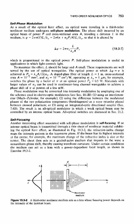
Self-Focusing Another interesting effect associated with self-phase modulation is self-focusing. If an intense optical beam is transmitted through a thin sheet of nonlinear material exhibit- ing the optical Kerr effect, as illustrated in Fig. 19.3-2, the refractive-index change maps the intensity pattern in the transverse plane. If the beam has its highest intensity at the center, for example, the maximum change of the refractive index is also at the center. The sheet then acts as a graded-index medium that imparts to the wave a nonuniform phase shift, thereby causing wavefront curvature. Under certain conditions the medium can act as a lens with a power-dependent focal length, as shown in Exercise 19.3-2.
Figure 19.3-2 A third-order nonlinear the intensity of the incident beam.
medium acts as a lens whose focusing power depends on
754 NONLINEAR OPTICS
EXERCISE 19.3-2
Optical Kerr Lens. An optical beam traveling in the z direction is transmitted through a thin sheet of nonlinear optical material exhibiting the optical Kerr effect, n(1) = iz + n21. The sheet lies in the x-y plane and has a small thickness d so that its complex amplitude transmittance is exp( -jnk,d). The beam has an approximately planar wavefront and an intensity distribution I = Z&l - (x2 + y2>/W2] at points near the beam axis (x, y +z W), where I, is the peak intensity and W is the beam width. Show that the medium acts as a thin lens with a focal length inversely proportional to I,. Hint: A lens of focal length f has a complex amplitude transmittance proportional to exp[jk,(x2 + y2)/2f], as shown in (2.4-6); see also Exercise 2.4-6 on page 63.
Spatial Solitons When an intense optical beam travels through a substantial thickness of nonlinear homogeneous medium, instead of a thin sheet, the refractive index is altered nonuni- formly so that the medium can act as a graded-index waveguide. Thus the beam can create its own waveguide. If the intensity of the beam has the same spatial distribution in the transverse plane as one of the modes of the waveguide that the beam itself creates, the beam propagates self-consistently without changing its spatial distribution. Under such conditions, diffraction is compensated by the nonlinear effect, and the beam is confined to its self-created waveguide. Such self-guided beams are called spatial solitons.
The self-guiding of light in an optical Kerr medium is described mathematically by the Helmholtz equation, [V2 + n2(I)kz]E = 0, where n(l) = n + n,I, k, = o/co, and I = jE12/277. This is a nonlinear differential equation in E, which is simplified by writing E = A exp( -jkz), where k = nk,, and assuming that the envelope A = A(x, z) varies slowly in the z direction (in comparison with the wavelength h = 2r/k) and does not vary in the y direction (see Sec. 2.2C). Using the approximation (a2/Jz2)[ A exp( -jkz>] = ( - 2 jk dA/dz - k2A) exp( -jkz), the Helmholtz equation be- comes
a2A -- ax2
2jkf$ + kz[n2(I) - n2]A = 0. (19.3-8)
Since the nonlinear effect is small (n,I < n), we write
[n2(I) - n’] = [n(I) - n][n(I) + n] = [n,I][2n] = 2nTy’2 = ?[Ai2, 0
so that (19.34) becomes
a2A dX2 + 3k2[A12A = 2jkz.
770 (19.3-9)
Equation (19.3-9) is the nonlinear Schrijdinger equation. One of its solutions is

THIRD-ORDER NONLINEAR OPTICS 755
(a) (b)
Figure 19.3-3 Comparison between (a) a Gaussian beam traveling in a linear medium, and (b) a spatial soliton (self-guided optical beam) traveling in a nonlinear medium.
where W0 is a constant, sech(*) is the hyperbolic-secant function, A, satisfies n,(Ai/277,) = l/k21Vt and z. = $kJVz = rwz/A is the Rayleigh range [see (3.1-21)]. The intensity distribution
I(x, z) =
is independent of z and has a width Wo, as illustrated in Fig. 19.3-3. The distribution in (19.3-10) is the mode of a graded-index waveguide with a refractive index n + n,I = n[l + (l/k2W,f) sech2(x/Wo)], so that self-consistency is assured. Since E = A exp( -jkz), the wave travels with a propagation constant k + l/42, = k(1 + A2/8r2Wz) and phase velocity c/(1 + A2/8,rr2W,f). The velocity is smaller than c for localized beams (small Wo) but approaches c for large Wo.
Raman Gain The nonlinear coefficient xc3) is in general complex-valued, xc3) = ~2) + jxf! The self-phase modulation in (19.3-7),
L Acp = 2~n,~P =
67rr), xC3) L ----P,
0 EO n2 h,A
is therefore also complex, so that the propagation phase factor exp( -jq) is a combina- tion of phase shift, Acp = (6,rr~,/~,)(~~~/n2)(L/h0A>P, and gain exp($yL), with a gain coefficient
12rrq, xf' 1 Y= -P
-TAoA EO
(19.3-11) Raman Gain
Coefficient
that is proportional to the optical power P. This effect, called Raman gain, has its origin in the coupling of light to the high-frequency vibrational modes of the medium, which act as an energy source providing the gain. For low-loss media, the Raman gain may exceed the loss at reasonable levels of power, so that the medium can act as an optical amplifier. With proper feedback, the amplifier can be made into a laser. This effect is exhibited in low-loss optical fibers. Fiber Raman lasers have been demon- strated.

756 NONLINEAR OPTICS
B. Four-Wave Mixing
We have so far examined the response of a third-order nonlinear medium to a single monochromatic wave. In Exercise 19.3-3, the response to a superposition of two waves is explored, and in the remainder of this section the process of four-wave mixing is discussed.
EXERCISE 19.3-3
Two- Wave Mixing. Examine the response of a third-order nonlinear medium to an optical field comprising two monochromatic waves of angular frequencies o1 and 02, 8(t) = Re{E(or) exp(jo,t>} + Re{E(w2) exp( jo,t)). Determine the components PNL(wl) and PNL(m2) of the polarization density, showing that the two waves can be mutually coupled in a two-wave mixing process without the aid of other auxiliary waves. As we have seen in Sec. 19.2C, two-wave mixing is not possible in a second-order nonlinear medium (except in the degenerate case). The process of two-wave mixing in photorefractive media is illustrated in Fig. 18.4-3.
Three-wave mixing is generally not possible in a third-order nonlinear medium. Three waves of distinct frequencies ol, 02, and o3 cannot be coupled by the system without the help of an auxiliary fourth wave. For example, there is generally no contribution to the component PNL(ul) by waves 2 and 3, except in degenerate cases (e.g., when o1 = 20~ - w2).
We now examine the case of four-wave mixing in a third-order nonlinear medium. We begin by determining the response of the medium to a superposition of three waves of angular frequencies wl, 02, and m3, with field
i?(t) = Re{ E( wt) exp( jwit)} + Re{ E( +) exp( jw2t)} + Re{ E( w3) exp( jw3t)}.
It is convenient to write .8(t) as a sum of six terms
g’(t) = c $(qJ ev(.b,t), (19.3-12) q= fl, f2, f3
where oeq = -oq and E( -w4) = E*(w,). Substituting (19.3-12) into (19.3-l), we write YNL as a sum of 63 = 216 terms,
9$&t) = p3’ c ~bq)~(~,)~(4 ew[ G, + w, + w&t]. 4, r,f= fl, *2, f3
(19.3-13)
Thus PNL is the sum of harmonic components of frequencies or,. . . ,3&r,. . . ,20, f 02, - - . , AI Wl + 02 f 03. The amplitude PNL(oq + o, + ol) of the component of frequency wq + o, + oI can be determined by adding appropriate permutations of 4, r, and 1 in (19.3-13). For example, PNL(03 + o4 - wi) involves six permutations,
hLb3 + 04 - ~1) = ~x’~‘E(o~)E(w~)E*(w~). (19.3-14)

THIRD-ORDER NONLINEAR OPTICS 757
EXERCISE 19.3-4
Optica/ Kerr Effect in the Presence of Three Waves. Three monochromatic waves with frequencies wl, 02, and o3 travel in a third-order nonlinear medium. Determine the complex amplitude of the component of PNL(t) in (19.3-13) at frequency ol. Show that this wave travels with a velocity cJ(n + n,l), where
n 3% (3) 2=zx 9
0
(19.3-15)
and I = I, + 21, + 213, with I, = lE(~~>1~/2~, I = 1,2,3. This effect is similar to the optical Kerr effect discussed earlier.
Equation (19.3-14) indicates that four waves of frequencies wl, 02, w3, and o4 are mixed by the medium if o2 = w3 + w4 - ol, or
1 @3 + O4 = @l + @2* ( Frsquenc;q-f;~;i;; Condition
This equation constitutes the frequency-matching condition for four-wave mixing. Assuming that waves 1, 3, and 4 are plane waves of wavevectors k,, k,, and k,, so
that E(o,) a exp( -jk, * r), LJ = 1,3,4, then (19.3-14) gives
PNL( w2) a exp( -jk, * r) exp( -jk, l r) exp(jk, *I-) = exp[ -j(k3 + k, - k,) ar],
so that wave 2 is also a plane wave with wavevector k, = k, + k, - k,, from which
1 k3+k4=kl+k2. 1 (19.3-17) Phase-Matching
Condition
Equation (19.3-17) is the phase-matching condition for four-wave mixing. The four-wave mixing process may also be interpreted as an interaction between
four photons. A photon of frequency o3 combines with a photon of frequency a4 to produce a photon of frequency o1 and another of frequency 02, as illustrated in Fig. 19.3-4. Equations (19.3-16) and (19.3-17) represent conservation of energy and momen- tum, respectively.
(a) W
Figure 19.3-4 Four-wave mixing: (a) the phase-matching condition; (b) interaction of four photons.

758 NONLINEAR OPTICS
C. Optical Phase Conjugation
The frequency-matching condition (19.3-16) is satisfied when all four waves are of the same frequency.
0 I= 02 = 03 = 04 = 0. (19.348)
The process is then called degenerate four-wave mixing. Assuming further that two the waves (waves 3 and 4) are uniform plane waves traveling in opposite directions,
of
E3(r) = A, exp( -jk, l r), Ed(r) = A, exp( -jk, l r), (19.3-19)
with
k, = -k,, (19.3-20)
and substituting (19.3-19) and (19.3-20) into (19.3-141, we see that the polarization density of wave 2 is 6,y(3)A3A,EF(r). This term corresponds to a source emitting an optical wave (wave 2) of complex amplitude
/ E2(r) a A3A4E,‘“(r)m j (19.3-21) Phase Conjugation
Since A, and A, are constants, wave 2 is proportional to a conjugated version of wave 1. The device serves as a phase conjugator. Waves 3 and 4 are called the pump waves and waves 1 and 2 are called the probe and conjugate waves, respectively. As will be demonstrated shortly, the conjugate wave is identical to the probe wave except that it travels in the opposite direction. The phase conjugator is a special mirror that reflects the wave back onto itself without altering its wavefronts.
To understand the phase conjugation process consider two simple examples:
EXAMPLE 19.3-1. Conjugate of a Plane Wave. If wave 1 is a uniform plane wave, E,(r) = A, exp( - jk, * r), traveling in the direction k,, then Q(r) = A r exp( jk, * r) is a uniform plane wave traveling in the opposite direction k, = -k,, as illustrated in Fig. 19.3-5(b). Thus the phase-matching condition (19.3-17) is satisfied. The medium acts as a special “mirror” that reflects the incident plane wave back onto itself, no matter what the angle of incidence is.
Figure 19.3-5 Reflection of a plane wave from (a) an ordinary mirror and (b) a phase conjugate mirror. (b)
THIRD-ORDER NONLINEAR OPTICS 759
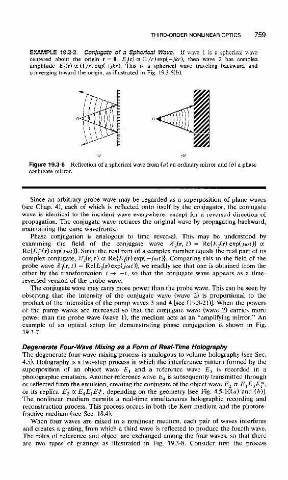
EXAMPLE 19.3-2. Conjtfgate of a Spherical Wave. If wave 1 is a spherical wave centered about the origin r = 0, E,(r) a (l/r) exp(-jkr), then wave 2 has complex amplitude E,(r) a (l/r> exp(+jkr). This is a spherical wave traveling backward and converging toward the origin, as illustrated in Fig. 19.3-6(b).
(UJ 16)
Figure 19.3-6 Reflection of a spherical wave from (a) an ordinary mirror and (b) a phase conjugate mirror.
Since an arbitrary probe wave may be regarded as a superposition of plane waves (see Chap. 4), each of which is reflected onto itself by the conjugator, the conjugate wave is identical to the incident wave everywhere, except for a reversed direction of propagation. The conjugate wave retraces the original wave by propagating backward, maintaining the same wavefronts.
Phase conjugation is analogous to time reversal. This may be understood by examining the field of the conjugate wave ZYz(r, t) = Re{E,(r) exp(jot)} a Re{ET(r) exp(jwt )}. Since the real part of a complex number equals the real part of its complex conjugate, ZY&, t) a Re{E,(r) exp( -jot)}. Comparing this to the field of the probe wave Z?r(r, t) = Re{E,(r) exp(jCr,t)}, we readily see that one is obtained from the other by the transformation t -+ -t, so that the conjugate wave appears as a time- reversed version of the probe wave.
The conjugate wave may carry more power than the probe wave. This can be seen by observing that the intensity of the conjugate wave (wave 2) is proportional to the product of the intensities of the pump waves 3 and 4 [see (19.3-21)]. When the powers of the pump waves are increased so that the conjugate wave (wave 2) carries more power than the probe wave (wave 1), the medium acts as an “amplifying mirror.” An example of an optical setup for demonstrating phase conjugation is shown in Fig. 19.3-7.
Degenerate Four-Wave Mixing as a Form of Real-Time Holography The degenerate four-wave mixing process is analogous to volume holography (see Sec. 4.5). Holography is a two-step process in which the interference pattern formed by the superposition of an object wave E, and a reference wave Es is recorded in a photographic emulsion. Another reference wave E, is subsequently transmitted through or reflected from the emulsion, creating the conjugate of the object wave E, a &E&F, or its replica E, a E,E,E3 *, depending on the geometry [see Fig. 4.5-10(a) and (6)]. The nonlinear medium permits a real-time simultaneous holographic recording and reconstruction process. This process occurs in both the Kerr medium and the photore- fractive medium (see Sec. 18.4).
When four waves are mixed in a nonlinear medium, each pair of waves interferes and creates a grating, from which a third wave is reflected to produce the fourth wave. The roles of reference and object are exchanged among the four waves, so that there are two types of gratings as illustrated in Fig. 19.3-8. Consider first the process

760 NONLINEAR OPTICS
Figure 19.3-7 An optical system for degenerate four-wave mixing using a nonlinear crystal. The pump waves 3 and 4, and the probe wave 1 are obtained from a laser using a beamsplitter and two mirrors. The conjugate wave 2 is created within the crystal.
Figure 19.3-8 Four-wave mixing in a nonlinear medium. A reference and object wave interfere and create a grating from which the second reference wave reflects and produces a conjugate wave. There are two possibilities corresponding to (a) transmission and (b) reflection gratings.
illustrated in Fig. 19.3-8(a) [see also Fig. 4.5-10(a)]. Assume that the two reference waves (denoted as waves 3 and 4) are counter-propagating plane waves. The two steps of holography are:
Step 1. The object wave 1 is added to the reference wave 3 and the intensity of their sum is recorded in the medium in the form of a volume grating (hologram).
Step 2. The reconstruction reference wave 4 is Bragg reflected from the grating to create the conjugate wave (wave 2).
This grating is called the transmission grating. The second possibility, illustrated in Fig. 19.3-8(b) is for the reference wave 4 to
interfere with the object wave 1 and create a grating, called the reflection grating, from which the second reference wave 3 is reflected to create the conjugate wave 2. These two gratings can exist together but they usually have different efficiencies.
In summary, four-wave mixing can provide a means for real-time holography and phase conjugation, which have a number of applications in optical signal processing.
THIRD-ORDER NONLINEAR OPTICS 761
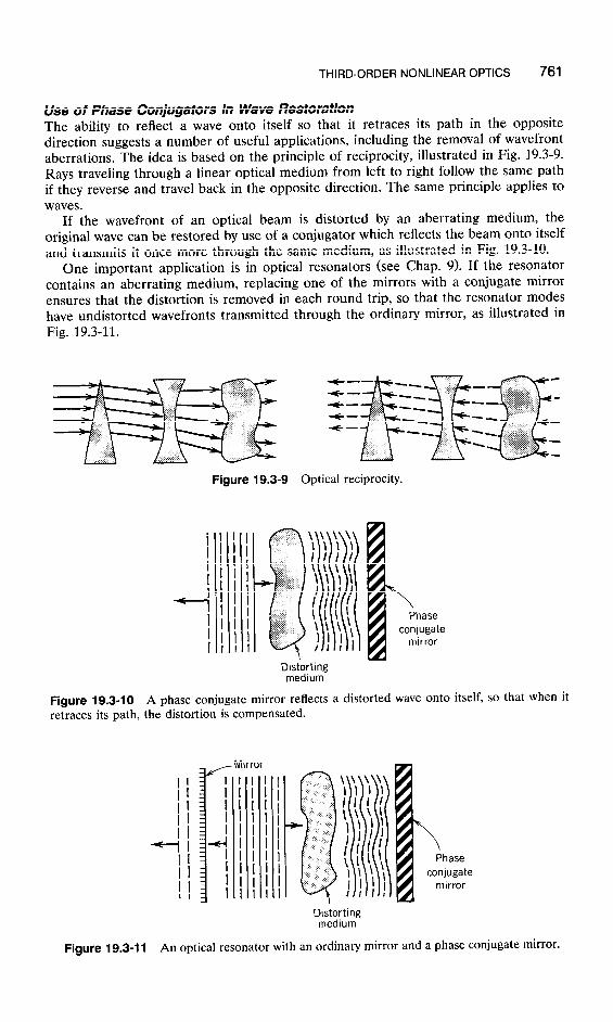
Use of Phase Conjugators in Wave Restoration The ability to reflect a wave onto itself so that it retraces its path in the opposite direction suggests a number of useful applications, including the removal of wavefront aberrations. The idea is based on the principle of reciprocity, illustrated in Fig. 19.3-9. Rays traveling through a linear optical medium from left to right follow the same path if they reverse and travel back in the opposite direction. The same principle applies to waves.
If the wavefront of an optical beam is distorted by an aberrating medium, the original wave can be restored by use of a conjugator which reflects the beam onto itself and transmits it once more through the same medium, as illustrated in Fig. 19.3-10.
One important application is in optical resonators (see Chap. 9). If the resonator contains an aberrating medium, replacing one of the mirrors with a conjugate mirror ensures that the distortion is removed in each round trip, so that the resonator modes have undistorted wavefronts transmitted through the ordinary mirror, as illustrated in Fig. 19.3-11.
Figure 19.3-9 Optical reciprocity.
i I I I
-4 I I I
Distorting medium
Figure 19.3-10 A phase conjugate mirror reflects a distorted wave onto itself, so that when it retraces its path, the distortion is compensated.
f
Distortmg medium
Figure 19.3-l 1 An optical resonator with an ordinary mirror and a phase conjugate mirror.

762 NONLINEAR OPTICS
*lg.4 COUPLED-WAVE THEORY OF THREE-WAVE MIXING
A quantitative analysis of the process of three-wave mixing in a second-order nonlinear optical medium is provided in this section using a coupled-wave theory. To simplify the analysis, the dispersive and anisotropic effects are not fully accounted for.
Coupled- Wave Equations Wave propagation in a second-order nonlinear medium is governed by the basic wave equation
where
(19.4-1)
(19.4-2)
is regarded as a radiation source, and
9 ,,=2&T2 (19.4-3)
is the nonlinear component of the polarization density. The field Z?(t) is a superposition of three waves of angular frequencies wl, 02, and
o3 and complex amplitudes E,, E,, and E,, respectively,
q=1,2,3 -
= C +[ Eq exp( jw,t) + E$ exp( -jW4t)]. q=1,2,3
It is convenient to rewrite (19.4-4) in the compact form
@t> = c $E, ew( jo,t ), q=+l, +2, f3
(19.4-4)
(19.4-5)
where o -4 = -wq and Ehp = E, . * The corresponding polarization density obtained by substituting into (19.4-3) is a sum of 36 terms
~NLW = 9 c E,E, w[ j(w, + dt], q,r= +1, +2, f3
(19.4-6)
and the corresponding radiation source,
9= &d c (wq + d2EqE, w[ j(aq + a&], (19.4-7) 4, r= f 1, *2, f3
is the sum of harmonic components of frequencies that are sums and differences of the original frequencies ol, 02, and 03.
Substituting (19.4-5) and (19.4-7) into the wave equation (19.4-l), we obtain a single differential equation with many terms, each of which is a harmonic function of some frequency. If the frequencies ol, 02, and o3 are distinct, we can separate this equation into three differential equations by equating terms on both sides of (19.4-1) at each of
COUPLED-WAVE THEORY OF THREE-WAVE MIXING 763
the frequencies ol, 02, and w3, separately. The result is cast in the form of three Helmholtz equations with sources,
(V2 + kf)E, = -S, (19.4-8a)
(V2 + k;)E, = -S, (19.4-8b)
(V2 + k,2)E, = -S,, (19.4-8c)
where S, is the amplitude of the component of 9 with frequency wq and k, = noq/co, q = 1,2,3. E ac o t h f h e complex amplitudes of the three waves satisfies the Helmholtz equation with a source equal to the component of 9 at its frequency. Under certain conditions, the source for one wave depends on the electric fields of the other two waves, so that the three waves are coupled.
In the absence of nonlinearity, d = 0 and the source term 9 vanishes so that each of the three waves satisfies the Helmholtz equation independently of the other two, as is expected in linear optics.
If the frequencies ol, 02, and o3 are not commensurate (one frequency is not the sum or difference of the other two, and one frequency is not twice another), then the source term Sa does not contain any components of frequencies ol, 02, or 03. The components S,, S,, and S, then vanish and the three waves do not interact.
For the three waves to be coupled by the medium, their frequencies must be commensurate. Assume, for example, that one frequency is the sum of the other two,
(19.4-9) Frequency-Matching
Condition
The source 9 then contains components at the frequencies ol, w2, and w3. Examin- ing the 36 terms of (19.4-7) we obtain
S, = 2/~,0: dE,E,*
S, = 2pp; dE,E,.
The source for wave 1 is proportional to E,E,* (since o1 = o3 - 02), so that waves 2 and 3 together contribute to the growth of wave 1. Similarly, the source for wave 3 is proportional to El E, (since o3 = o1 + w2), so that waves 1 and 2 combine to amplify wave 3, and so on. The three waves are thus coupled or “mixed” by the medium in a process described by three coupled differential equations in El, E,, and E,,
(V2 + k,2)E, = -2p,4dE3E~ (19.4-10a)

764 NONLINEAR OPTICS
EXERCISE 19.4-l
Degenerate Three- Wave Mixing. Equations (19.4-10) are valid only when the frequen- cies wl, w2, and w3 are distinct. Consider now the degenerate case for which w1 = w2 = w and 0.1~ = 2w, so that there are two, instead of three, waves with amplitudes E, and E,. Show that these waves satisfy the Helmholtz equation with sources
S, = 2p04 dE,E,*
so that the coupled wave equations are
( V2 + kf) E, = -2p04 dE,ET (19.4-1 la)
( V2 + k;) E, = -pow; dE,E1. (19.4-11 b)
Note that these equations are not obtained from the three-wave-mixing equations (19.4-10) by substituting E, = E, [the factor of 2 is absent in (19.4-lib)].
Mixing of Three Collinear Uniform Plane Waves Assume that the three waves are plane waves traveling in the z direction with complex amplitudes E, = A, exp( -jk,z), complex envelopes A,, and wavenumbers k, = &i/c, 4 = 1,2,3. It is convenient to normalize the complex envelopes by defining the variables aq = A,/(27&0,)~“~, 77, = b,/4
A ,^ where q = q,/n is -the impedance of the medium, ‘IL is the impedance of free space, and AU, is the energy of a photon of
angular frequency oq. Thus
E, = (2qho,)1’2~, exp( -jk,z), 4 = 1,2,3, (19.4-12)
and the intensities of the three waves are I4 = IE,12/277 = ho,la,12. The photon flux densities (photons/s-m2> associated with these waves are
c/l4 = $ = laq12. 4
(19.4-13)
The variable aq therefore represents the complex envelope of wave q, scaled such that laq12 is the photon flux density. This scaling is convenient since the process of wave mixing must be governed by photon-number conservation (see Sec. 19.2C).
As a result of the interaction between the three waves, the complex envelopes a4 vary with z so that aq =aq (z). If the interaction is weak, the aq(z) vary slowly with z, so that they can be assumed approximately constant within a distance of a wavelength. This makes it possible to use the slowly varying envelope approximation wherein d2aq/dz2 is neglected relative to k, da,/dz = (277/A,) da,/dz and
(V” + ki)[ a9 exp( -jkqz)] = -j2kq2 exp( -jkqz) (19.4-14)

COUPLED-WAVE THEORY OF THREE-WAVE MIXING
(see Sec. 2.20. With this approximation (19.4-10) reduce to the simpler form
765
where
and
da, - = -jpa3a; dz
exp( -jAkz)
da2 - = -jp+aT exp( -jAkz) dz
da3 - = -jya1a2exp( jhkz), dz
(19.4-16)
Ak = k, - k, - k, (19.4-17)
(19.4-l 5a)
(19.4-m) Three-Wave Mixing Coupled Equations
represents the error in the phase-matching condition. The variations of al, a2, and a3
with z are therefore governed by three coupled first-order differential equations (19.4-15), which we proceed to solve under the different boundary conditions corre- sponding to various applications. It is useful, however, first to derive some invariants of the wave-mixing process. These are functions of al, a2, and a3 that are independent of z. Invariants are useful since they can be used to reduce the number of independent variables. Exercises 19.4-2 and 19.4-3 develop invariants based on conservation of energy and conservation of photons.
EXERCISE 19.4-2
Energy Conservation. Show that the sum of the intensities I4 = hwqlaq12, q = 1,2,3, of the three waves governed by (19.4-15) is invariant to z, so that
-&I, + I, + 13) = 0. (19.4-18)
EXERCISE 19.4-3
Photon-Number Conservation: The Manley-Rowe Relation. Using (19.4-B), show that
flal12 = fla212 = - %la312, (19.4-19)
from which the Manley-Rowe relation (19.2-171, which was derived using photon-number conservation, follows. Equation (19.4-19) implies that Iall + la312 and la212 + la312 are also invariants of the wave-mixing process.
766 NONLINEAR OPTICS
A. Second-Harmonic Generation
Second-harmonic generation is a degenerate case of three-wave mixing in which
0 1=w2=0 and os=20. (19.4-20)
Two forms of interaction occur:
n Two photons of frequency o combine to form a photon of frequency 2w (second harmonic).
n One photon of frequency 20 splits into two photons, each of frequency w.
The interaction of the two waves is described sources. Conservation of momentum requires that
by the Helmholtz equations with
k, = 2k,. (19.4-21)
EXERCISE 19.4-4
Coupled- Wave Equations for Second-Harmonic Generation. Apply the slowly vary- ing envelope approximation (19.4-14) to the Helmholtz equations (19.4-ll), which describe two collinear waves in the degenerate case, to show that
da1 dz = -JP3a1 * exp( -jAkz) (19.4-22a)
da3 - = -j$zIaI exp( j Akz), dz
(19.4-22b)
where Ak = k, - 2k, and
f2 = 4hW3173d2. (19.4-23)
Assuming two collinear waves with perfect phase matching (Ak = 0), equations (19.4-22) reduce to
da1 -= dz -.iy+$ (19.4-24a)
4 B -= dz
-j-apl. 2
(19.4-24b)
Coupled Equations (Second-Harmonic
Generation)
At the input to the device (Z = 0) the amplitude of the second-harmonic wave is assumed to be zero, us(O) = 0, and that of the fundamental wave, at(O), is assumed to be real. With these boundary conditions, and using the photon-number conservation
COUPLED-WAVE THEORY OF THREE-WAVE MIXING 767
relation IaI( + 21 as(z)I2 = constant, (19.4-24) can be shown to have the solution
al(z) =a,(O) sech PT
Plm z as(z) = - --&z,(O) tanh T.
( 19.4-25a)
(19.4-25b)
Consequently, the photon flux densities 4&z) = IaI( and &(z) = [as( evolve in accordance with
&(z) = &(O) sech2$ (19.4-26a)
&(z) = ;~$,(0) tanh2y, (19.4-26b)
where y/2 = par(O)/ fi, i.e.,
Y2 = 2p24(O> = 2p2&(0) = 8d2q3hW”&(0) = 8d2Tj3W21,(0). (19.4-27)
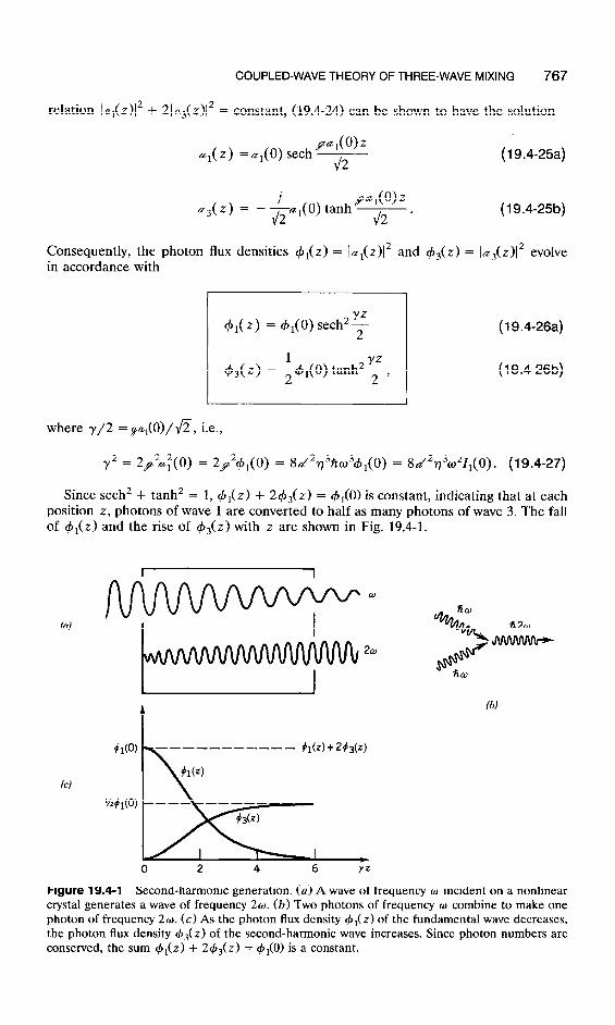
Since sech2 + tanh2 = 1, +r(z) + 2&(z) = #r(O) is constant, indicating that at each position z, photons of wave 1 are converted to half as many photons of wave 3. The fall of 4,(z) and the rise of +3(z) with z are shown in Fig. 19.4-1.
91(O)
(c)
l~#l(o)
W
0 2 4 6
Figure 19.4-1 Second-harmonic generation. (a) A wave of frequency o incident on a nonlinear crystal generates a wave of frequency 20. (b) Two photons of frequency w combine to make one photon of frequency 20. (c) As the photon flux density +r(z> of the fundamental wave decreases, the photon flux density c#J~(z) of the second-harmonic wave increases. Since photon numbers are conserved, the sum ~$r(z) + 2#1~(2.) = 4,(O) is a constant.

768 NONLINEAR OPTICS
The efficiency of second-harmonic generation for an interaction region of length L is
YL = tanh2---2-. (19.4-28)
For large yL (long cell, large input intensity, or large nonlinear parameter), the efficiency approaches one. This signifies that all the input power (at frequency w) has been transformed into power at frequency 20; all input photons of frequency o are converted into half as many photons of frequency 20.
For small yL [small device length L, small nonlinear parameter d, or small input photon flux density ~$r(0)], the argument of the tanh function is small and therefore the approximation tanh x = x may be used. The efficiency of second-harmonic generation is then
I3( L) - = iy2L2 = gL2&(o) = 2d2773hw3L24,(0) = 2d2773W2L21,(0), Ii(O)
so that
where P = I,(O)A is the incident optical power and A is the cross-sectional area. The efficiency is proportional to the input power P and the factor d2/n3, which is a figure of merit used for comparing different nonlinear materials. For a fixed input power P, the efficiency is directly proportional to the geometrical factor L2/A. To maximize the efficiency we must confine the wave to the smallest possible area A and the largest possible interaction length L. This is best accomplished with waveguides (planar or channel waveguides or fibers).
Effect of Phase Mismatch To study the effect of phase (or momentum) mismatch, the general equations (19.4-22) are used with Ak # 0. For simplicity, we limit ourselves to the weak-coupling case for which yL < 1. In this case, the amplitude of the fundamental wave G,(Z) varies only slightly with z [see Fig. 19.4-l(c)], and may be assumed approximately constant. Substituting a,(z) =ar(O) in (19.4-22b) and integrating, we obtain
&3(L) = -j$-@f’exp(jAkz’) dz’ = - (&)af(O)[exp( j AkL) - 11, 0
(19.4-30)
from which 43(L) = ja3(L>12 = (~/Ak>2~~(0)sin2(AkL/2), where al(O) is assumed
COUPLED-WAVE THEORY OF THREE-WAVE MIXING 769
2 1 -- -- 0 1 2 BK L L L L 2l7
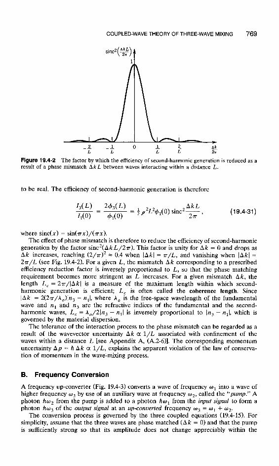
Figure 19.4-2 The factor by which the efficiency of second-harmonic generation is reduced as a result of a phase mismatch Ak L between waves interacting within a distance L.
to be real. The efficiency of second-harmonic generation is therefore
I,(L) W,(L) AkL - = Ii(O)
--..--- = $f2L2+1(0) sinc2T, 41(O)
(19.4-31)
where sine(x) = sin(rx>/(rx). The effect of phase mismatch is therefore to reduce the efficiency of second-harmonic
generation by the factor sinc2(Ak L/27). This factor is unity for Ak = 0 and drops as Ak increases, reaching (2/~>~ = 0.4 when I Ak I = T/L, and vanishing when 1 Akl = 27c/L (see Fig. 19.4-2). For a given L, the mismatch Ak corresponding to a prescribed efficiency reduction factor is inversely proportional to L, so that the phase matching requirement becomes more stringent as L increases. For a given mismatch Ak, the length L, = 2rr/lAkl is a measure of the maximum length within which second- harmonic generation is efficient; L, is often called the coherence length. Since IAkl = 2(27r/hJn3 - nr[, where A, is the free-space wavelength of the fundamental wave and n1 and n3 are the refractive indices of the fundamental and the second- harmonic waves, I,, = A,/2)n3 - n,) is inversely proportional to In3 - nr[, which is governed by the material dispersion.
The tolerance of the interaction process to the phase mismatch can be regarded as a result of the wavevector uncertainty Ak a l/L associated with confinement of the waves within a distance L [see Appendix A, (A.2-6)]. The corresponding momentum uncertainty Ap = A Ak a l/L, explains the apparent violation of the law of conserva- tion of momentum in the wave-mixing process.
B. Frequency Conversion
A frequency up-converter (Fig. 19.4-3) converts a wave of frequency o1 into a wave of higher frequency o3 by use of an auxiliary wave at frequency ti2, called the “pump.” A photon %zo2 from the pump is added to a photon Awl from the input signal to form a photon Aw3 of the output signal at an up-converted frequency o3 = o1 + 02.
The conversion process is governed by the three coupled equations (19.4-B). For simplicity, assume that the three waves are phase matched (Ak = 0) and that the pump is sufficiently strong so that its amplitude does not change appreciably within the

770 NONLINEAR OPTICS
interaction distance of interest; i.e., a?(z) = a:, (0) for all z between 0 and L. The three equations (19.4-15) then reduce to two, -
da1 -= dz
da3 .y -= dz -J?w
(19.4-32a)
(19.4-32b)
where y = 2pa,(O) and a&O) is assumed real. These are simple differential equations with harmonic solutions
al( 2) =a,(O) cosy ( 19.4-33a)
a~( Z) = -jai(O) sin:. (19.4-33b)
The corresponding photon flux densities are
(bl( 2) = &(O) cos2T
+3(~) = c$~(O) sin2F.
(19.4-34a)
(19.4-34b)
Dependences of the photon flux densities +i and & on z are sketched in Fig. 19.4-3(c). Photons are exchanged periodically between the two waves. In the region between z = 0 and z = r/y, the input w1 photons combine with the pump o2 photons and generate the up-converted o3 photons. Wave 1 is therefore attenuated, whereas wave 3 is amplified. In the region yz = r to yz = 2~, the o3 photons are more abundant; they disintegrate into o1 and o2 photons; so that wave 3 is attenuated and wave 1 amplified. The process is repeated periodically as the waves travel through the medium.
The efficiency of up-conversion for a device of length L is
I,(L) 03 . 2YL
II(O) = iy sm 2 * (19.4-35)
For yL -=x 1, and using (19.4-16), this is approximated by I,(L)/I,(O) = (w,/w,)(~L/2>~ = (03/~1>8~L~42(O> = 205L2d2q312(0), from which
where A is the cross-sectional area and P, = I,(O)A is the pump power. The conver- sion efficiency is proportional to the pump power, the ratio L2/A, and the material parameter d2/n3.

COUPLED-WAVE THEORY OF THREE-WAVE MIXING 771
(al
Input I I signal ml
ti I output signal
I I
Pump ~2
2 I
(b)
g3(t) l/y&L+ 0 n 2n 3n YZ
Figure 19.4-3 The frequency up-converter: (a) wave mixing; (b) photon interactions; (c) evolution of the photon flux densities of the input W,-wave and the up-converted 03-wave. The pump 02-wave is assumed constant.
EXERCISE 19.4-5
Infrared Up-Conversion. An up-converter uses a proustite crystal (d = 1.5 x lo-” MKS, n = 2.6). The input wave is obtained from a CO, laser of wavelength 10.6 pm, and the pump from a 1-W Nd 3+*YAG laser of wavelength 1.06 pm focused to a cross-sectional . area 10e2 mm2 (see Fig. 19.2-5). Determine the wavelength of the up-converted wave and the efficiency of up-conversion if the waves are collinear and the interaction length is 1 cm.
C. Parametric Amplification and Oscillation
Parametric Amplifiers The parametric amplifier uses three-wave mixing in a nonlinear crystal to provide optical gain [Fig. 19.4-4(a)]. The process is governed by the same three coupled equations (19.4-15) with the waves identified as follows:
. Wave 1 is the “signal” to be amplified. It is incident on the crystal with a small intensity I,(O).
n Wave 3, called the “pump,” is an intense wave that provides power to the amplifier.
n Wave 2, called the “idler,” is an auxiliary wave created by the interaction process.
772 NONLINEAR OPTICS
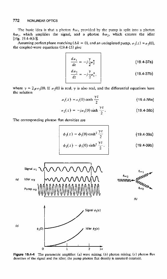
The basic idea is that a photon tio3 provided by the pump is split into a photon which amplifies the signal, and a photon fiw*, which creates the idler
$I 19.4-4(6)]. Assuming perfect phase matching (Ak = O), and an undepleted pump, a&z) = as(O),
the coupled-wave equations (19.4-15) give
4 -= dz
da2 -= dz
( 19.4-37a)
(19.4-37b)
where y = 29@,(O). If a?(O) is real, y is also real, and the differential equations have the solution - -
al(z) =al(0) cash y
YZ .+(z) = -j&t(O) sinh 2.
The corresponding photon flux densities are
4,(z) = &(O) cosh2 T
+2(z) = 4i(O) sinh2 F.
(19.4-38a)
(19.4-38b)
(19.4-39a)
(19.4-39b)
Signal 01
(a) Idler 02
Pump 03
Signal #l(z)
Idler #2(z)
Figure 19.4-4 The parametric amplifier: (a) wave mixing; (b) photon mixing; (c) photon flux densities of the signal and the idler; the pump photon flux density is assumed constant.
COUPLED-WAVE THEORY OF THREE-WAVE MIXING 773
Both 4*(z) and &,(z) grow monotonically with z, as illustrated in Fig. 19.4-4(c). This growth saturates when sufficient energy is drawn from the pump so that the assumption of an undepleted pump no longer holds.
The total gain of an amplifier of length L is G = 4,(L)/4,(0) = cosh2(yl/2). In the limit yL z+ 1, G = (erLi2 + e-yL/2)2/4 = eYL/4, so that the gain increases exponentially with yL. The gain coefficient y = 2paJO) = 2d(2hw,w2w,~3)1’2n3(0), from which
where P, = I,(O)A and A is the cross-sectional area.
(19.4-40) Parametric Amplifier
Gain Coefficient
EXERCISE 19.4-6
Gain of a Parametric Amplifier. An S-cm-long ADP crystal (n = 1.5, d = 7.7 x 1O-24 MKS) is used to amplify He-Ne laser light of wavelength 633 nm. The pump is an argon laser of wavelength 334 nm and intensity 2 MW/cm2. Determine the gain of the amplifier.
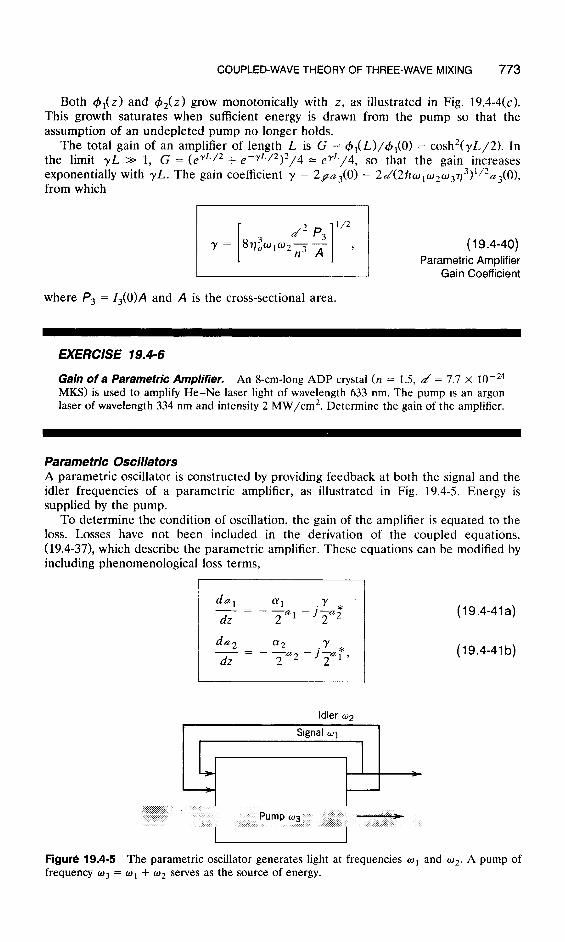
Parametric Oscillators A parametric oscillator is constructed by providing feedback at both the signal and the idler frequencies of a parametric amplifier, as illustrated in Fig. 19.4-5. Energy is supplied by the pump.
To determine the condition of oscillation, the gain of the amplifier is equated to the loss. Losses have not been included in the derivation of the coupled equations, (19.4-37), which describe the parametric amplifier. These equations can be modified by including phenomenological loss terms,
dUl (xl -=
dz - -u1
2
da2 ff2 -= ay *
dz -a,-J-u
2 2 l’
z Pump 03
I----
Idler ~2
(19.4-41a)
(19.4-41 b)
Figure 19.4-5 The parametric oscillator generates light at frequencies o1 and 02. A pump of frequency w3 = o1 + w2 serves as the source of energy.

774 NONLINEAR OPTICS
where al and a2 are power attenuation coefficients for the signal and idler waves, respectively. These terms represent scattering and absorption losses in the medium and losses at the mirrors of the resonator [see Fig. 19.2-7(c)] distributed along the length of the crystal as was done with the laser (see Sec. 14.1). In the absence of coupling (y = 0), (19.4-41a) gives &i(z) = exp(-cu,z/2)a,(O), and 4i(z) = exp(-a,z)+,(O), so that the photon flux decays at a rate cyl. Equation (19.4-41b) gives a similar result.
The steady-state solution of (19.4-41) is obtained by equating the derivatives to zero,
0 = alal + jyrz; (19.4-42a)
0 = ‘Y2a2 +jya r- (19.4-4213)
Equation (19.4-42a) gives al/~; = -jy/cr, and the conjugate of (19.4-42b) gives da2 * = a2/jy, so that for a nontrivial solution, -jy/crt = a,/jy, from which
y2 = (YlcY2. (19.4-43)
If (Y~ = a2 = a, the condition of oscillation becomes y = (Y, meaning that the amplifier gain coefficient equals the loss coefficient. Since y = 2pas(O), the amplitude of the pump must be as(O) 2 a/29 and the corresponding photon flux density 43(O) 2 (Y2/4f12. Substituting from (19.4-16) for p, we obtain +s(O) 2 a2/8Ao,W2W3T)3d2.
metric oscillation is Thus the minimum w-w intensity Ao343Ko required for para-
The oscillation frequencies oi and o2 of the parametric oscillator are determined by the frequency- and phase-matching conditions, o1 + w2 = w3 and nlwl + n2w2 = n303. The solution of these two equations yields o1 and w2. Since the medium is always dispersive the refractive indices are frequency dependent (i.e., n1 is a function of ol, It2 is a function of 02, and n3 is a function of 03). The oscillation frequencies may be tuned by varying the refractive indices using, for example, temperature control.
*I95 COUPLED-WAVE THEORY OF FOUR-WAVE MIXING
We now derive the coupled differential equations that describe four-wave mixing in a third-order nonlinear medium, using an approach similar to that employed in the three-wave mixing case.
Coupled- Wave Equations Four waves constituting a total field
iqt) = C Re[ E, exp( jwat )] 4=1,2,3,4
c 34 exp( &t) (19.51) q=fl, *2, +3, f4

COUPLED-WAVE THEORY OF FOUR-WAVE MIXING 775
travel in a medium characterized by a nonlinear polarization density
9 NL, = 4,zy’3’kF3. (19.5-2)
The corresponding source of radiation, 9 = -p, d2g,,/at2, is therefore a sum of 83 = 512 terms,
9 = f/&3) c ( oq + wp + ar)2E,EpEr exp[ j( oq + oP + wr)t]. q,p,r= fl, +2, k3, *4
(19.5-3)
Substituting (19.5-l) and (19.5-3) into the wave equation (19.4-l) and equating terms at each of the four frequencies ol, w2, 03, and 04, we obtain four Helmholtz equations with sources,
(V’+ k;)E, = -S,, 4 = W,W, (19.5-4)
where S, is the amplitude of the component of 9 at frequency wq. For the four waves to be coupled, their frequencies must be commensurate.
Consider, for example, the case for which the sum of two frequencies equals the sum of the other two frequencies,
Three waves can then combine and create a source at the fourth frequency. Using (19.55), terms in (19.5-3) at each of the four frequencies are
Sl = ,uJ.o~~~~)(~E~E,E~ + 3E,[IEl12 + 2)E212 + 21E312 + 21E412]) (19.5-6a)
S, = pow&(“)(6E3E4E~ + 3E2[ IE212 + 21E,12 + 21E312 + 21E412]) (19.5-6b)
S, = ,~L,~~~(~)(~E,E,E,* + 3E3[JE,12 + 21E212 + 2(E,12 + 21E,[‘]) (19.5-6c)
S4 = ~JO~~(~)[~E,E,E~ + 3E,[ IE412 + 2)E,12 + 2)E212 + 21E312]]. (19.5-661)
Each wave is therefore driven by a source with two components. The first is a result of mixing of the other three waves. The first term in S,, for example, is proportional to E,E,E-f and therefore represents the mixing of waves 2, 3, and 4 to create a source for wave 1. The second component is proportional to the complex amplitude of the wave itself. The second term of S,, for example, is proportional to E,, so that it plays the role of refractive-index modulation, and therefore represents the optical Kerr effect (see Exercise 19.3-4).
It is therefore convenient to separate the two contributions to these sources by defining
S, = s, + (~~/co)~Ax~E,, q = 1,2,3,4 (19.5-7)
776 NONLINEAR OPTICS
where
s, = ~/.LJo:x(~)E~ E, E$ (19.58a)
s, = 6/~~02,x(~)E, E, E,* (19.5-8b)
s, = G~J&(~)E~ E, E; (19.58c)
& = 6p,w~~(~)E, E, E;, (19.5-8d)
and
Axq = 6:xc3’(21 - I,>, q = 1,2,3,4. (19.5-9) 0
Here Iq = lEqj2/2q are the intensities of the waves, I = I, + I2 + I3 + I4 is the total intensity, and 77 is the impedance of the medium.
This enables us to rewrite the Helmholtz equations (19.54) as
(V2 + k;)E, = -I,, q = L2,3,4, (19.5-10)
where
and
671 l/2 -7’3’(21 - IJ 1 [ 6q
l/2 =nl+-
eon2’ (“(21 - I&
0 1 ==nl+-
L 3q (“(21 - IJ , l on2’ 1
from which
where
which matches with (19.3-15).
370
n2 = E,n2xt3j,
(19.5-lla)
Optical Kerr Effect
(19.5-lib)
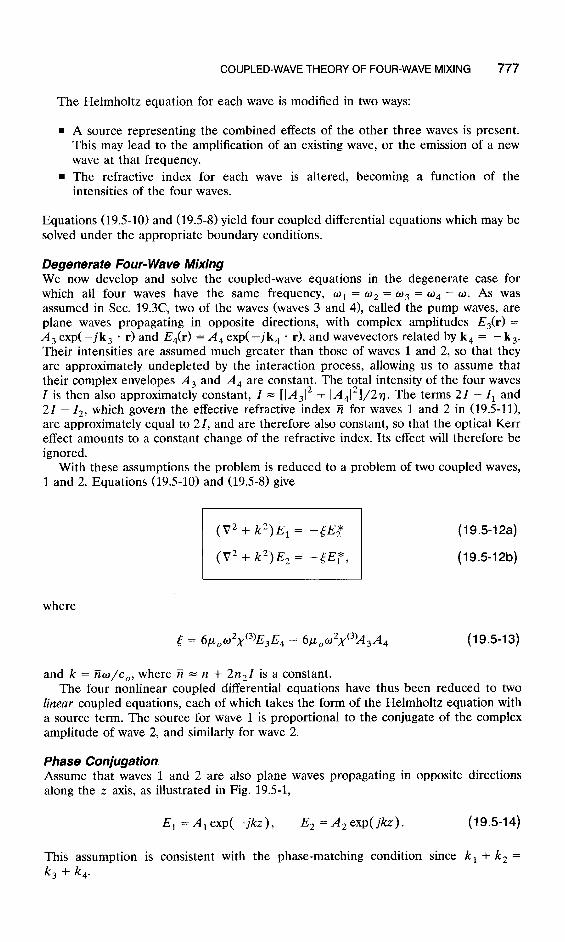
COUPLED-WAVE THEORY OF FOUR-WAVE MIXING 777
The Helmholtz equation for each wave is modified in two ways:
n A source representing the combined effects of the other three waves is present. This may lead to the amplification of an existing wave, or the emission of a new wave at that frequency.
9 The refractive index for each wave is altered, becoming a function of the intensities of the four waves.
Equations (19.510) and (19.58) yield four coupled differential equations which may be solved under the appropriate boundary conditions.
Degenerate Four- Wave Mixing We now develop and solve the coupled-wave equations in the degenerate case for which all four waves have the same frequency, w1 = o2 = o3 = o4 = o. As was assumed in Sec. 19.3C, two of the waves (waves 3 and 4), called the pump waves, are plane waves propagating in opposite directions, with complex amplitudes E,(r) = A3 exp( -jk, * r) and E4(r) = A, exp( -jk, l r), and wavevectors related by k, = -k,. Their intensities are assumed much greater than those of waves 1 and 2, so that they are approximately undepleted by the interaction process, allowing us to assume that their complex envelopes A, and A, are constant. The total intensity of the four waves I is then also approximately constant, I = [lA312 + IA412]/2~. The terms 21 - I, and 21 - 12, which govern the effective refractive index ?i for waves 1 and 2 in (19.5111, are approximately equal to 21, and are therefore also constant, so that the optical Kerr effect amounts to a constant change of the refractive index. Its effect will therefore be ignored.
With these assumptions the problem is reduced to a problem of two coupled waves, 1 and 2. Equations (19.510) and (19.5-8) give
(V2 + k2)E, = -tEz
(V2 + k2)E2 = -[Ef,
(19.512a)
(19.512b)
6 = 6poo2~(3)E3E4 = ~,u,~~x(~)A~A, (19.543)
and k = Tie/co, where 7i = n + 2n21 is a constant. The four nonlinear coupled differential equations have thus been reduced to two
linear coupled equations, each of which takes the form of the Helmholtz equation with a source term. The source for wave 1 is proportional to the conjugate of the complex amplitude of wave 2, and similarly for wave 2.
Phase Conjugation Assume that waves 1 and 2 are also plane waves propagating in opposite directions along the z axis, as illustrated in Fig. 19.5-1,
E, = A, exp( -jkz), E, = A,exp( jkz). (19.5-14)
This assumption is consistent with the phase-matching condition since k, + k, = k, + k,.

778 NONLINEAR OPTICS
3
Figure 19.5-1 Degenerate four-wave mixing. Waves 3 and 4 are intense pump waves traveling in opposite directions. Wave 1, the probe wave, and wave 2, the conjugate wave, also travel in opposite directions and have increasing amplitudes.
Substituting (19.514) in (19.512) and using the slowly varying envelope approxima- tion, (19.4-14), we reduce equations (19.512) to two first-order differential equations,
dA1 - = -j.yAz
dz
dA2 - = jyAr,
dz
(19.515a)
where
5 3w7
Y=2k= n -xc3)A3 A, (19.5-16)
is a coupling coefficient. For simplicity, assume that A,A, is real, so that y is real. The solution of (19.515)
is then two harmonic functions A,(t) and A,(z) with a 90” phase shift between them. If the nonlinear medium extends over a distance between the planes z = -L to z = 0, as illustrated in Fig. 19.5-1, wave 1 has amplitude A,( -L) = Ai at the entrance plane, and wave 2 has zero amplitude at the exit plane, A,(O) = 0. Under these boundary
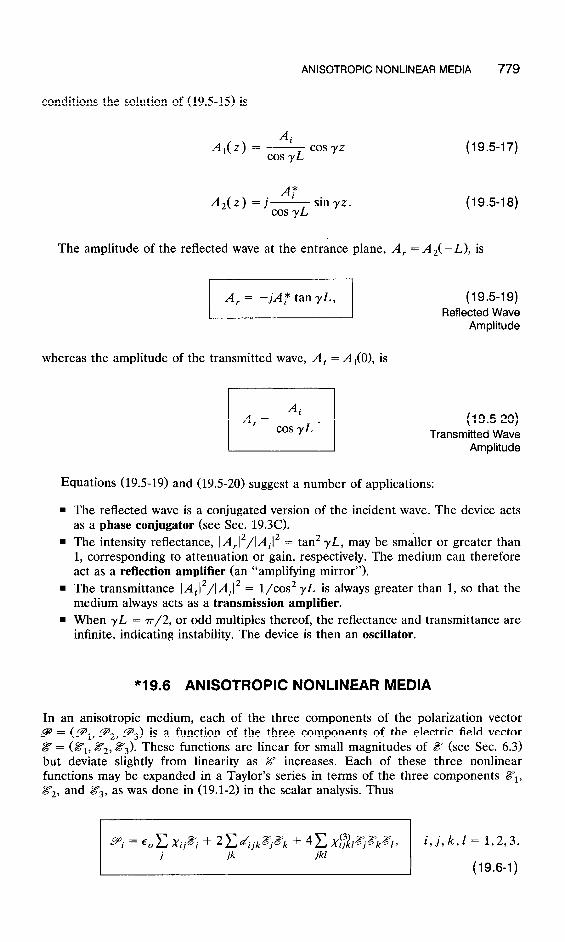
ANISOTROPIC NONLINEAR MEDIA 779
conditions the solution of (19.515) is
Ai A,(z) = -
cos yL cos yz
Ai* AZ(z) = j-
cos yL sin yz.
(19.547)
(19.518)
The amplitude of the reflected wave at the entrance plane, A, = A&-L), is
(19.5-19) Reflected Wave
Amplitude
whereas the amplitude of the transmitted wave, A, = A,(O), is
(19.5-20) Transmitted Wave
Amplitude
Equations (19.519) and (19520) suggest a number of applications:
n The reflected wave is a conjugated version of the incident wave. The device acts as a phase conjugator (see Sec. 19.30
. The intensity reflectance, IA,12/IAi12 = tan2 yL, may be smaller or greater than 1, corresponding to attenuation or gain, respectively. The medium can therefore act as a reflection amplifier (an “amplifying mirror”).
. The transmittance IA,12/IAi12 = l/cos2 yL is always greater than 1, so that the medium always acts as a transmission amplifier.
n When yL = 7r/2, or odd multiples thereof, the reflectance and transmittance are infinite, indicating instability. The device is then an oscillator.
*19.6 ANISOTROPIC NONLINEAR MEDIA
In an anisotropic medium, each of the three components of the polarization vector 9 = (gi, g2, 9s) is a function of the three components of the electric field vector 8 = (Z?i, &Y2, 8s). These functions are linear for small magnitudes of .Z (see Sec. 6.3) but deviate slightly from linearity as Z increases. Each of these three nonlinear functions may be expanded in a Taylor’s series in terms of the three components ZYi, ?Z2, and Z?s, as was done in (19.1-2) in the scalar analysis. Thus
pi = E, C Xij~ + 2 Ca/ijk~~k + 4 C X~~~l~~k~l, i, j, k,l = 1,2,3. j ik jkl
(19.6-1)
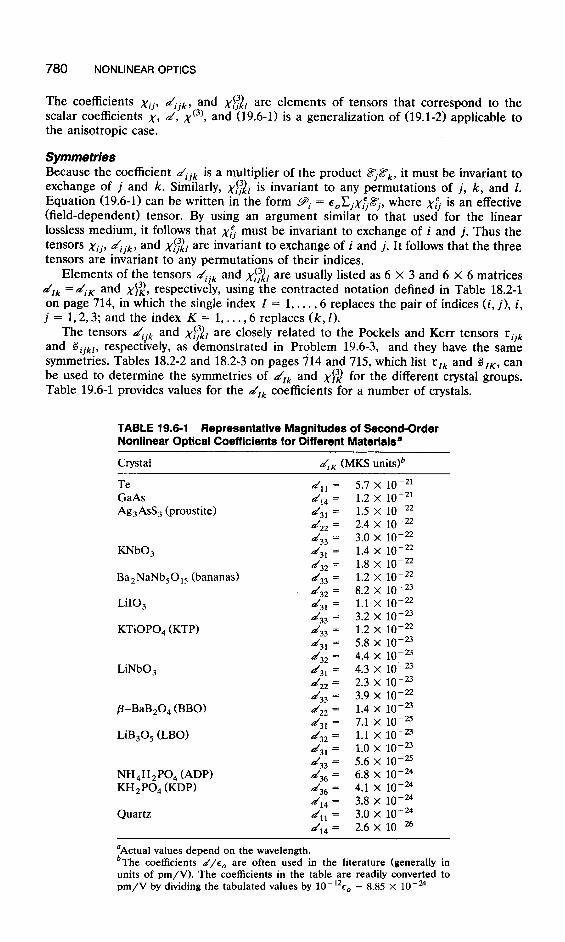
780 NONLINEAR OPTICS
The coefficients xii, dijk, and x$& are elements of tensors that correspond to the scalar coefficients x, d, xC3), and (19.6-l) is a generalization of (19.1-2) applicable to the anisotropic case.
Symmetries Because the coefficient C2/ijk is a multiplier of the product Ajax, it must be invariant to exchange of j and k. Similarly, ~$2~ is invariant to any permutations of j, k, and 1. Equation (19.6-l) can be written in the form pi = E,CjX~~j, where ~5 is an effective (field-dependent) tensor. By using an argument similar to that used for the linear lossless medium, it follows that ~5 must be invariant to exchange of i and j. Thus the tensors Xi j, dijk, and xi;,& are invariant to exchange of i and j. It follows that the three tensors are invariant to any permutations of their indices.
Elements of the tensors drjk and ~$2~ are usually listed as 6 X 3 and 6 X 6 matrices drk =diK and ~$2, respectively, using the contracted notation defined in Table 18.2-1 on page 714, in which the single index I = 1,. . . ,6 replaces the pair of indices (i, j), i, j = 1,2,3; and the index K = 1, . . . ,6 replaces (k, I).
The tensors diik and ~$2~ are closely related to the Pockels and Kerr tensors rijk and Gijk/, respectively, as demonstrated in Problem 19.6-3, and they have the same symmetries. Tables 18.2-2 and 18.2-3 on pages 714 and 715, which list rlk and GIK, can be used to determine the symmetries of d,k and ~$2 for the different crystal groups. Table 19.6-1 provides values for the drk coefficients for a number of crystals.
TABLE 19.6-l Representative Magnitudes of Second-Order Nonlinear Optical Coefficients for Different Materials8
Crystal diiK (MKS units)’
Te GaAs Ag,AsS, (proustite)
KNbO,
Ba,NaNb,O,, (bananas)
LiIO,
KTiOPO, (KTP)
LiNbO,
P-BaB*O, (BBO)
LiB,O, (LBO)
NH,H,PO, (ADP) KH,PO4 GDP)
Quartz
d,, = 5.7 x 10-Z’ cd,, = 1.2 x lo-
J31 = 1.5 x 10-t: d22 = 2.4 x 1O-22 d33 = 3.0 x 10⁻²² d3, = 1.4 x lo- d32 = 1.8 x 10-t:
d33 = d32 =
1.2 x 10-i; 8.2 X lo-
d3* = 1.1 x 1o-22 d33 = 3.2 x lo- d33 = 1.2 x 10-z f&f31 = 5.8 x lo- d32 = 4.4 X lo-’ cd31 = 4.3 x 10-u d22 = 2.3 x lo-=
d33 = 3.9 x lo-”
d22 = 23
lq4 x lo-25 d31 = 7.1 x lo- d32 = 1.1 X 1O-23 cd31 = 1.0 x lo- 23
A33 = 5.6 x lo-= d36 = 6.8 x lo-” d36 = 4.1 x 1o-24 cdl4 = 3.8 x 1O-24 d,, = 3.0 x 1o-24
Al4 = 2.6 x 1O-26
‘Actual values depend on the wavelength. bThe coefficients d/e0 are often used in the literature (generally in units of pm/V). The coefficients in the table are readily converted to pm/V by dividing the tabulated values by 10-12c, = 8.85 x lo-%

ANISOTROPIC NONLINEAR MEDIA 781
EXERCISE 19.6- 1
KDP. Use Table 18.2-2 on page 714 to verify that for crystals of 42m symmetry, such as potassium dihydrogen phosphate (KDP),
91 = %JXlFl + 24$33 (19.6-2)
92 = %lX22~2 + 24$1~3 (19.6-3)
93 = c,x33g3 + 2453&~2, (19.6-4)
where the axes 1,2,3 are the principal axes of the crystal. Determine the nonlinear polarization density vector for an electric field g in the x-y plane at an angle of 45” with the x and y axes.
Three- Wave Mixing in Anisofropic Second-Order Nonlinear Media An optical field 8(t) comprising two monochromatic linearly polarized waves of angular frequencies w1 and o2 and complex amplitudes E(o,) and E(o,) is applied to a second-order nonlinear crystal. The component of the polarization density vector at frequency o3 = o1 + o2 may be determined by using the relation
pi(w3) = 2CdijkEj(al)Ek(W2), j, k = 1,2,3, (19.6-5) ik
where Ej(ol), Ek(02), and P&o,) are components of these vectors along the principal axes of the crystal. This equation is a generalization of (19.2-lld).
If Ej(w,) = E(wl) cos 8lj and Ek(a2) = E(02)COS 82k, where 8lj and 82, are the angles the vectors E(o,) and E(o,) make with the principal axes, then (19.6-5) may be written in the form
pi+31 = %&h)E(4, (19.6-6)
where
deff = C di jk COS 8 lj COS 82,) i, j, k = 1,2,3. (19.6-7)
Equation (19.6-6) is in the form used in the scalar formulation in Sets. 19.2C and 19.4, where d eff plays the role of the a( coefficient.
Phase Matching in Three-Wave Mixing As shown in Sec. 19.2C, the phase-matching condition k, = k, + k, is necessary for efficient wave mixing. This condition is equivalent to ti3n3ii3 = alnlfil + 02n2ii2, where ii,, G,, and ii, are unit vectors in the directions of propagation of the waves. We assume that the three waves are normal modes of the crystal (see Sec. 6.3) with phase velocities c,/na, co/q,, and co/n,. Note that n,, nb, and n, depend on the directions of the waves, their polarizations, and on the frequencies. In a uniaxial crystal, n,, nb, and n, may be the ordinary or extraordinary indices.
As an example, consider second-harmonic generation in a uniaxial crystal with waves traveling in the same direction. Assuming that waves 1 and 2 are identical, w 1=w2= o, and o3 = 20, the phase-matching condition becomes n, = n,. It is then

782 NONLINEAR OPTICS
Figure 19.6-1 Matching the extraordinary refractive index of the fundamental wave to the ordinary refractive index of the second-harmonic wave.
necessary to find the direction and polarizations of the two waves such that the wave of frequency o has the same refractive index as the wave of frequency 20.
As explained in Sec. 6.3, the normal modes for a wave traveling in a uniaxial crystal with refractive indices n, and n, are an ordinary wave with refractive index n, (independent of d irection) and an extraordinary wave with refractive index n(O) satisfying l/n2(@) = cos2 S/n: + sin2 e/n:, where 8 is the angle between the direction of the wave and the optic axis. The dependence of these two refractive indices on 8 is illustrated by the ellipse and the circle in Fig. 19.6-l (see also Fig. 6.3-11). Since n, and n, are frequency dependent, we denote them as n:, It?, n:, nz” and represent the ellipse/circle at the fundamental frequency o by solid curves and the ellipse/circle at the second-harmonic 20 by dashed curves. To match n, = n”(O) to nb = ny, a direction is found for which the circle at 20 intersects the ellipse at w, as illustrated in Fig. 19.6-1. This is achieved by selecting an angle 8 for which
1 cos2 8 sin2 9 -=- - nfj (nz)’ + (n,)”
Thus the fundamental an ordinary wave.
wave is an extraordinary wave and the second-harmonic wave is
*lg.7 DISPERSIVE NONLINEAR MEDIA
This section provides a brief discussion of the origin of dispersion and its effect on nonlinear optical processes. For simplicity, anisotropic effects are not included. A dispersive medium is a medium with memory (see Sec. 5.2); the polarization density P(t) resulting from an applied electric field Z(t) does not occur instantaneously. The response g(t) at time t is a function of the applied electric field kY( t ‘> at times t ’ 5 t. When the medium is also nonlinear, the functional relation between 5@(t) and {i!‘(t’>, t’ zz t} is nonlinear. There are two means for describing such nonlinear dynamical systems:
. A phenomenological integral relation between 9(t) and 8(t) based on an expansion, similar to the Taylor’s series expansion, called the Volterra series expansion. The coefficients of the expansion characterize the medium phe-
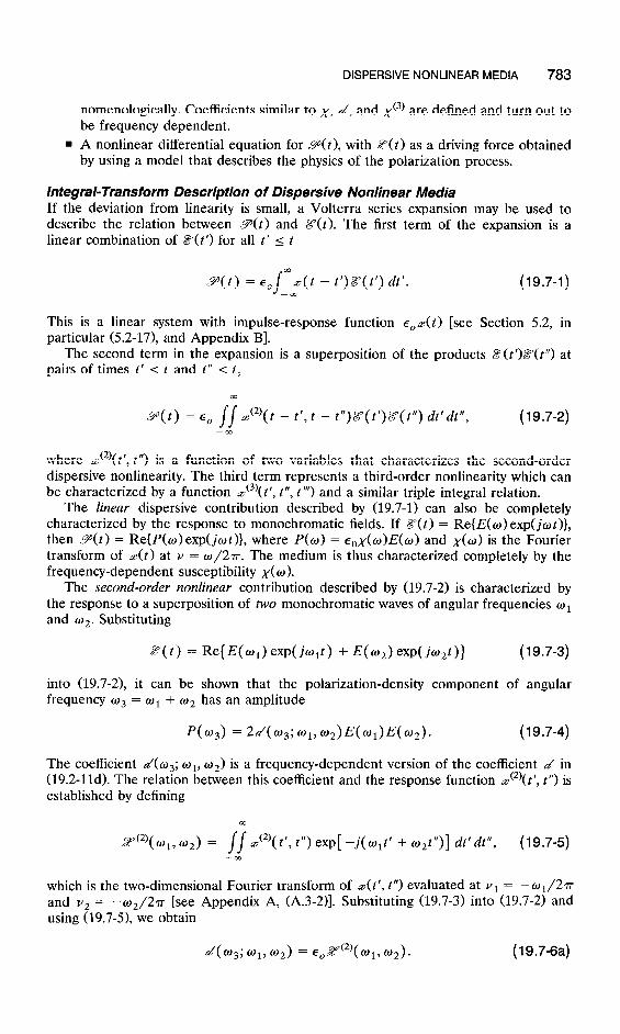
DISPERSIVE NONLINEAR MEDIA 783
nomenologically. Coefficients similar to ,y, d, and xc3) are defined and turn out to be frequency dependent.
n A nonlinear differential equation for Y(t), with E’(t) as a driving force obtained by using a model that describes the physics of the polarization process.
Integral-Transform Description of Dispersive Nonlinear Media If the deviation from linearity is small, a Volterra series expansion may be used to describe the relation between P(t) and Z?(t). The first term of the expansion is a linear combination of ii? for all t’ I t
9(t) = ~,jmz(t - t’)g(t’) dt’. --cc
(19.7-1)
This is a linear system with impulse-response function E’,z(~) [see Section 5.2, in particular (5.2-17), and Appendix B].
The second term in the expansion is a superposition of the products E(t’)Z?(t”) at pairs of times t’ I t and t” I t,
9(t) = E, t - t’, t - t’)Z=(t’)8’(t”) dt’dt”, (19.7-2) --m
where ~(~)(t’, t”) is a function of two variables that characterizes the second-order dispersive nonlinearity. The third term represents a third-order nonlinearity which can be characterized by a function ~(~)(t’, t”, t”‘) and a similar triple integral relation.
The linear dispersive contribution described by (19.7-1) can also be completely characterized by the response to monochromatic fields. If 8(t) = Re{E(w) exp(jot )}, then P(t) = Re{P(w)exp(jwt)}, where P(U) = E,&o)E(w) and x(w) is the Fourier transform of z(t) at ZJ = w/2~. The medium is thus characterized completely by the frequency-dependent susceptibility x( 0).
The second-order nonlinear contribution described by (19.7-2) is characterized by the response to a superposition of two monochromatic waves of angular frequencies oi and w2. Substituting
8(t) = Re{ E( oi) exp( k+t) + E( 4 exp(.W)} (19.7-3)
into (19.7-2), it can be shown that the polarization-density frequency o3 = o1 + m2 has an amplitude
component of angular
P(o3) = 240 3; 019 W2PhPb2). (19.7-4)
The coefficient 4~~; ol, 02) is a frequency-dependent version of the coefficient d in (19.2-lld). The relation between this coefficient and the response function ~(~)(t’, P’) is established by defining
03
2Y’2’( 01, 02) = // st2)( t’, t”) exp[ -j( tilt’ + m2t”)] dt’dt”, (19.7-5) --00
which is the two-dimensional Fourier transform of ~(t ‘, , “) evaluated at v1 = -01/2r and v2 = -02/27r [see Appendix A, (A.3-2)]. Substituting (19.7-3) into (19.7-2) and using (19.7-5), we obtain
40 3; 01, fu2) = E 0 2Y(2)(01, 02)* (19.7-6a)

784 NONLINEAR OPTICS
Thus the second-order nonlinear dispersive medium is completely characterized by either of the frequency-dependent functions, Z(2)(o,, w2) or 40s; wl, 02).
The degenerate case of second-harmonic generation in a second-order nonlinear medium is also readily described by substituting 8(t) = Re{E(w) exp(jwt)} into (19.7-2) and using (19.7-5). The resultant polarization has a component at frequency 2w with amplitude P(20) = a/(2 o; o, o)E(w)E(o), where
d(2w w w) = &oiY(2)( w w) , , , - (19.7-613)
Other d coefficients representing various wave mixing processes may similarly be related to the two-dimensional function Z(2)(o,, 02). The electro-optic effect, for example, is a result of interaction between a steady field (wr = 0) and an optical wave (02 = U) to generate a polarization density at o3 = w. The pertinent coefficient for this interaction is d(o; 0, U) = ~E$Y(~)(w, 0). This is the coefficient that determines the Pockels coefficient r in accordance with (19.2-10).
In a third-order nonlinear medium, an electric field comprising three harmonic functions of angular frequencies wl, 02, and w3 creates a sum-frequency polar- ization density with a component at angular frequency w4 = o1 + o2 + w3 of amplitude P(04) = 6xc3)(w4; wl, 02, w~)E(u~)E(~~)E(u~), where the function x(~)(o~; wl, w2, w3) replaces the coefficient x c3) which describes the nondispersive case. The function ~(~~(0,; ol, 02, ws) can be determined from ~(~)(t’, t”, l”‘) by relations similar to (19.7-6a).
In summary: As a consequence of dispersion, the second- and third-order nonlinear coefficients d and xc31 are dependent on the frequencies of the waves involved in the wave mixing process.
Differential-Equation Description of Dispersive Nonlinear Media An example of a nonlinear dynamic relation between p(t) and E’(t) described by a differential equation is the relation
d29 d9
dt2 +a dt - + ~$9 + o&,xob~2 = O;E,X& (19.7-7)
where u, oo, x0, and b are constants. Without the nonlinear term c&o,yob92, this equation describes a medium in which each atom is described by the harmonic-oscilla- tor model of an electron of mass m subject to an electric-field force eZ?‘, an elastic restraining force --KX, and a frictional force mu ak/dt, where x is the displacement of the electron from its equilibrium position and m. = (~/rrz)l/~ is the resonance angular frequency (see Sec. 5X). The medium is then linear and dispersive with a susceptibil- ity
When the restraining force is a nonlinear function of displacement, -KX - K~x~,
where K and ~~ are constants, we have an anharmonic oscillator described by (19.7-7), where b is proportional to K~. The medium is then nonlinear.

DISPERSIVE NONLINEAR MEDIA 785
EXERCISE 19.7-l
Polarization Density. Show that for a medium containing N atoms per unit volume, each modeled as an anharmonic (nonlinear) oscillator with restraining force --KX - K~x~, the relation between Y(t) and Z?(t) is the nonlinear differential equation (19.7-7), where ,yo = Ne2/mo&, and b = u2/e3N2.
Equation (19.7-7) cannot be solved exactly. However, if the nonlinear term is small, an iterative approach provides an approximate solution. We write (19.7-7) in the form
L?(9) = 27 - bP2, (19.7-9)
where .LZ = (~&~x,,>-‘(d~/dt~ + ad/& + 0;) is a linear differential operator. The iterative solution of (19.7-9) is described by the following steps:
9 Find a first-order approximation ~?i by neglecting the nonlinear term bP2 in (19.7-9), and solving the linear equation
L?{Pl} = 8. (19.740)
. Use this approximate solution to determine the small nonlinear term ~LPF.
. Obtain a second-order approximation by solving (19.7-9) with the term &P2 replaced by 69:. The solution of the resultant linear equation is denoted P2,
2{9,} = rz - 69f. (19.7-11)
n Repeat the process to obtain a third-order approximation as illustrated by the block diagram of Fig. 19.7-1.
We first examine the special case of monochromatic light, Z? = Re{E(w) exp(jwt)}. In the first iteration Pi = Re{Pi(o) exp(jot)}, where P,(u) = E,x(o)E(w) and x(w) is given by (19.743). In the second iteration, the linear system is driven by a force
27 - 69: = Re( E( ti)ejwt) - b [ Re[e,x( o) eiOf]] 2
= Re(E(o)eiwt) - tb Re([e,x(W)E(W)]2ei20’) - $ie0x(~)E(~)12.
Since these three terms have frequencies o, 20, and 0, the linear system responds with
Figure 19.7-1 Block diagram representing the nonlinear differential equation (19.7-9). The linear system represented by the operator equation 2&F} = 8 has a transfer function E&O).
786 NONLINEAR OPTICS
susceptibilities x(w), x(20), and x(O), respectively. The component of P2 at fre- quency 20 has an amplitude P,(20) = E,x(~u){ - ~b[~~x(w)E(o)]~}. Since P(20) = 420; W, w)E(o)E(o), we conclude that
I I
d(2w;o,w) = -4bE,2[x(4]2x(2w). (19.7-12)
EXERCISE 19.7-2
Miller’s Rule. Show that for the nonlinear resonant medium described by (19.7-7) if the light is a superposition of two monochromatic waves of angular frequencies o1 and 02, then the second-order approximation described by (19.7-10) and (19.7-11) yields a compo- nent of polarization at frequency o3 = o1 + o2 with amplitude P2(~3) = 2d(w 3; q, OJ~E(~E(~, where
Equation (19.7-13) is known as Miller’s rule.
Miller’s rule states that the coefficient of second-order nonlinearity for the genera- tion of a wave of frequency o3 = o1 + o2 from two waves of frequencies w1 and o2 is proportional to the product x(o~)x(o~)x(o~) of the linear susceptibilities at the three frequencies. The three frequencies must therefore lie within the optical transmission window of the medium (away from resonance). If these frequencies are much smaller than the resonance frequency oo, dh3; al, 02) = - ;b&&
then (19.7-8) gives x(o) = x0, and (19.7-13) yields which is independent of frequency. The medium is then
approximately nondispersive, and the results of the previous sections in which disper- sion was neglected are applicable. Miller’s rule also indicates that materials with large refractive indices (large x0) tend to have large d.
19.8 OPTICAL SOLITONS
When a pulse of light travels in a linear dispersive medium its shape changes continuously because its constituent frequency components travel at different group velocities and undergo different time delays [see Sec. 5.6 and Fig. 19.8-l(a)]. If the medium is also nonlinear, self-phase modulation (which results, for example, from the optical Kerr effect) alters the phase, and therefore the frequency, of the weak and intense parts of the pulse by unequal amounts. As a result of group-velocity dispersion, different parts of the pulse travel at different group velocities and the pulse shape is altered. The interplay between self-phase modulation and group-velocity dispersion can therefore result in an overall pulse spreading or pulse compression, depending on the magnitudes and signs of these two effects.
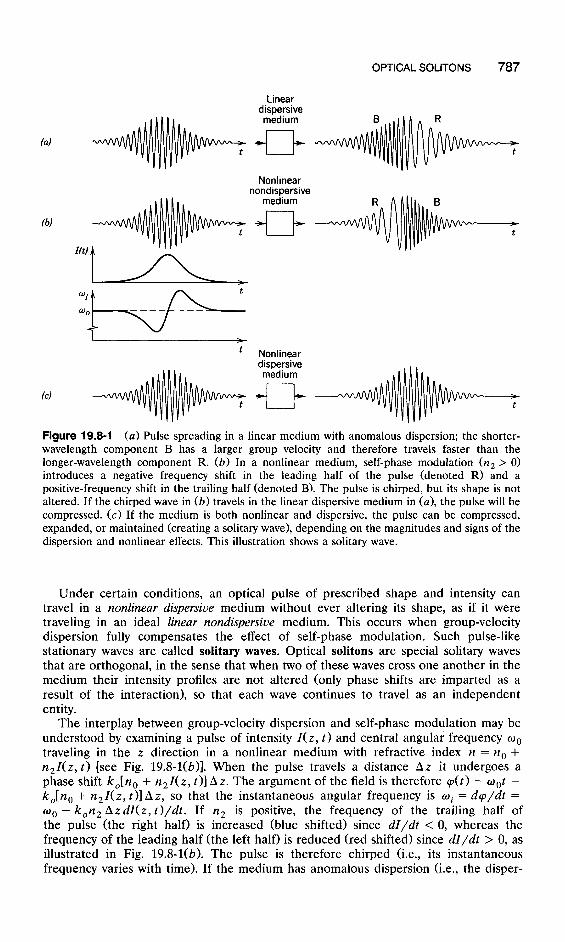
OPTICAL SOLITONS 787
Linear diwersive mbdium
+-cl+
Nonlinear nondispersive
medium
+ck
y+f
t Nonlinear dispersive medium
cl+-
Figure 19.8-1 (a) Pulse spreading in a linear medium with anomalous dispersion; the shorter- wavelength component B has a larger group velocity and therefore travels faster than the longer-wavelength component R. (b) In a nonlinear medium, self-phase modulation (n, > 0) introduces a negative frequency shift in the leading half of the pulse (denoted R) and a positive-frequency shift in the trailing half (denoted B). The pulse is chirped, but its shape is not altered. If the chirped wave in (b) travels in the linear dispersive medium in (a), the pulse will be compressed. (c) If the medium is both nonlinear and dispersive, the pulse can be compressed, expanded, or maintained (creating a solitary wave), depending on the magnitudes and signs of the dispersion and nonlinear effects. This illustration shows a solitary wave.
Under certain conditions, an optical pulse of prescribed shape and intensity can travel in a nonlinear dispersive medium without ever altering its shape, as if it were traveling in an ideal linear nondispersive medium. This occurs when group-velocity dispersion fully compensates the effect of self-phase modulation. Such pulse-like stationary waves are called solitary waves. Optical solitons are special solitary waves that are orthogonal, in the sense that when two of these waves cross one another in the medium their intensity profiles are not altered (only phase shifts are imparted as a result of the interaction), so that each wave continues to travel as an independent entity.
The interplay between group-velocity dispersion and self-phase modulation may be understood by examining a pulse of intensity l(z, t) and central angular frequency w0 traveling in the z direction in a nonlinear medium with refractive index n = no + n,I(z, t) [see Fig. 19.&l(b)]. When the pulse travels a distance AZ it undergoes a phase shift k&n, + n,I(z, t)] AZ. The argument of the field is therefore cp(t) = oat - k,[n, + n,I(z, t)] AZ, so that the instantaneous angular frequency is wi = dq/dt = o. - k0n2 AzdI(z, t)/dt. If n2 is positive, the frequency of the trailing half of the pulse (the right half) is increased (blue shifted) since dI/dt < 0, whereas the frequency of the leading half (the left half) is reduced (red shifted) since dI/dt > 0, as illustrated in Fig. 19.8-l(b). The pulse is therefore chirped (i.e., its instantaneous frequency varies with time). If the medium has anomalous dispersion (i.e., the disper-

788 NONLINEAR OPTICS
sion coefficient D, is positive, or the coefficient p” = d2/3/du2 [see (5.6-9)] is negative), the group velocity decreases with increasing wavelength. Thus the blue-shifted half of the pulse travels faster than the red-shifted half. As a result, the blue-shifted half catches up with the red-shifted half and the pulse is compressed (a related situation occurs in a medium with normal dispersion as shown in Fig. 5.6-4; this effect is used to generate ultrashort light pulses).
At a certain level of intensity and for certain pulse profiles, the effects of self-phase modulation and group-velocity dispersion are balanced so that a stable pulse, a soliton, travels without spread, as illustrated in Fig. 19.8-l(c). The chirping effect of self-phase modulation perfectly compensates the natural pulse expansion caused by the group- velocity dispersion. Any slight spreading of the pulse enhances the compression process, and any pulse narrowing reduces the compression process, so that the pulse shape and width are maintained. Solitons can be thought of as the modes (eigenfunc- tions) of a nonlinear dispersive system. A mathematical analysis of this phenomenon is based on solutions of the nonlinear wave equation that governs the propagation of the pulse envelope, as described subsequently.
The optical solitons described in this section are analogous to spatial solitons (self-guided beams). As explained in Sec. 19.3A, spatial solitons are monochromatic waves that are localized spatially in the transverse plane. They travel in a nonlinear medium without altering their spatial distribution, as a result of a balance between diffraction and self-phase modulation. Thus, spatial solitons are the transverse analogs of longitudinal (temporal) optical solitons. This analogy is not surprising since diffrac- tion is the spatial equivalent of dispersion. The phenomena are described by the same differential equation, with space and time interchanged. In fact the term soliton refers to generic solutions describing pulses that propagate without change; they may be temporal or spatial.
Differential Equation for the Wave Envelope To describe the propagation of an optical pulse in a nonlinear dispersive medium we start with the wave equation (19.1-3),
(19.84)
where gL and TNL are the linear and the nonlinear components of the polarization density, respectively. Since the medium is dispersive, PL( t) is related to Z’:(t) by a time integral, the convolution in (5.2-17). The component PNL is related to k!Y by the nonlinear relation LPNL = 4x (3)ZY3 assumed here to be approximately instantaneous. Thus (19.8-1) gives a nonlinear integrodifferential equation in 8’. Clearly, some approx- imations are necessary in order to solve this equation.
It is convenient to combine the linear terms in (19.8-1) and write
where
(19.8-2)
(19.8-3)
Since LP~ is linearly related to 8, F must also be linearly related to .E’. If &? =
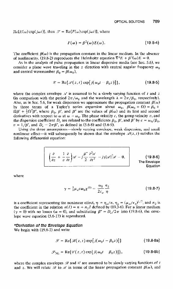
OPTICAL SOLITONS 789
Re{E(o) exp(jot)}, then 9 = Re{F(o) exp(jot)}, where
F(w) = ,32(w)E(w). (19.8-4)
The coefficient p(o) is the propagation constant in the linear medium. In the absence of nonlinearity, (19.8-2) reproduces the Helmholtz equation V2E + p2(w>E = 0.
As in the analysis of pulse propagation in linear dispersive media (see Sec. 5.6), we consider a plane wave traveling in the z direction with central angular frequency w0 and central wavenumber PO = /3(00),
ii? = Re{ &( z, t) exp[ j(o,$ - &z)]}, (19.8-5)
where the complex envelope @ is assumed to be a slowly varying function of t and z (in comparison with the period 27r/00 and the wavelength h = 27r/&, respectively). Also, as in Sec. 5.6, for weak dispersion we approximate the propagation constant p(o) by three terms of a Taylor’s series expansion about wo, P(oo + a) = PO + Qp’ + $fi2p”, where PO, /3’, and p” are the values of p(w) and its first and second derivatives with respect to LC) at o = oo. The phase velocity c, the group velocity u, and the dispersion coefficient D, are related to the coefficients PO, p’, and /3” by c = wo/po, u = l/p’, and Dv = 27rTTp”, as defined in (5.6-8) and (5.6-9).
Using the three assumptions-slowly varying envelope, weak dispersion, and small nonlinear effect-it will subsequently be shown that the envelope M(z, t) satisfies the following differential equation:
where
@o n2 Y = h.&w,x (3) = - -
2% rl (19.8-7)
is a coefficient representing the nonlinear effect, 7 = q,/n, q0 = (P,/E,)‘/~, and n2 is the coefficient in the relation n(I) = n + n2 I defined by (19.3-6). For a linear medium (y = 0) with no losses (a = 0), and substituting p” = D,/27r into (19.S6), the enve- lope wave equation (5.6-17) is reproduced.
*Derivation of the Envelope Equation We begin with (19.8-2) and write
9 = Re{ g( z, t) exp[ j&t - ~az>] 1 (19.8-8a)
(19.8-8b)
where the complex envelopes L@ and E? are assumed to be slowly varying functions of t and z. We will relate LB to & in terms of the linear propagation constant p(o), and
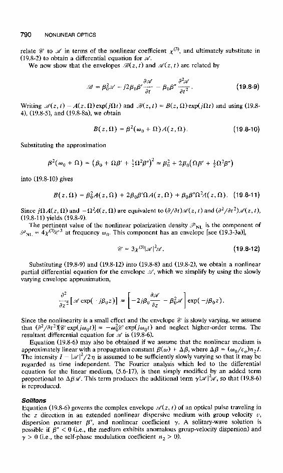
790 NONLINEAR OPTICS
relate I?? to M in terms of the nonlinear coefficient ~(~1, and ultimately substitute in (19.8-2) to obtain a differential equation for M.
We now show that the envelopes B(z, t) and &(z, t) are related by
Writing J&Z, t) = A(z, n)exp(jfit) and 2%~) t) = B(z, Q)exp(jQt) and using (19.8- 4), (19.8-S) and (19.8-8a), we obtain
B(z,R) = /3’(wo + il)A(zJk). (19.840)
Substituting the approximation
py w. + Ln) = (PO + np’ + ;n2p”)’ = p,’ + 2p,( np’ + $2p,r)
into (19.8-10) gives
B(z,i-l) = &A(z,fl) + 2&P’flA(z,fl) + /30P”~2A(z,~). (19.8-11)
Since jS1A(z, a) and -Ln2A(z, a) are equivalent to (a/dt)d(z, t) and (a2/at2>dz, t), (19.8-11) yields (19.8-9).
The pertinent value of the nonlinear polarization density PNL is the component of 9 NL = 4x (3)2Y3 at frequency wo. This component has an envelope [see (19.3-3a)],
$27 = 3x'3'(9q2d . (19.842)
Substituting (19.8-9) and (19.8-12) into (19.8-8) and (19.8-2), we obtain a nonlinear partial differential equation for the envelope s’, which we simplify by using the slowly varying envelope approximation,
a2
[
ad a22[&exp(-jPoZ)] = -2j/?,,z -P+ exp(-jP0z).
I
Since the nonlinearity is a small effect and the envelope Z? is slowly varying, we assume that (a2/dt2)[%9 exp( ju,t)] = - wg$Y exp( jw, t ) and neglect higher-order terms. The resultant differential equation for d is (19.8-6).
Equation (19.8-6) may also be obtained if we assume that the nonlinear medium is approximately linear with a propagation constant p(w) + Ap, where Ap = (oo/c,)n21. The intensity I = (&‘i2/2q is assumed to be sufficiently slowly varying so that it may be regarded as time independent. The Fourier analysis which led to the differential equation for the linear medium, (5.6-17), is then simply modified by an added term proportional to Apti. This term produces the additional term rl~lTr;s, so that (19.8-6) is reproduced.
Solitons Equation (19.8-6) governs the complex envelope J&Z, t) of an optical pulse traveling in the z direction in an extended nonlinear dispersive medium with group velocity U, dispersion parameter p”, and nonlinear coefficient y. A solitary-wave solution is possible if p” < 0 (i.e., the medium exhibits anomalous group-velocity dispersion) and y > 0 (i.e., the self-phase modulation coefficient n2 > 0).
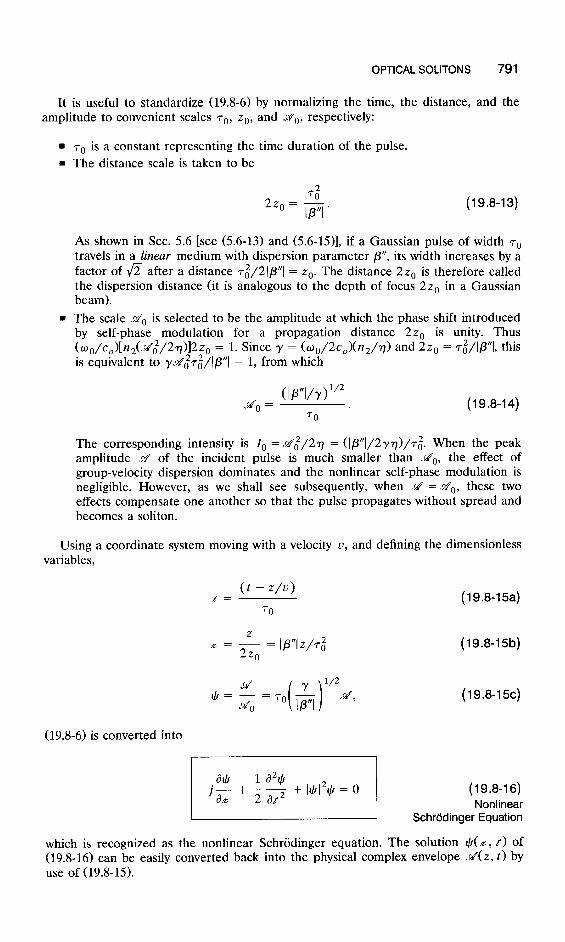
OPTICAL SOLITONS 791
It is useful to standardize (19.8-6) by normalizing the time, the distance, and the amplitude to convenient scales 70, zo, and do, respectively:
= 7. is a constant representing the time duration of the pulse. n The distance scale is taken to be
G 2zo= Ip”I’ (19.8-13)
As shown in Sec. 5.6 [see (5.6-13) and (5.6-15)], if a Gaussian pulse of width r. travels in a linear medium with dispersion parameter p”, its width increases by a factor of fi after a distance 7~/21p”I = zo. The distance 2z, is therefore called the dispersion distance (it is analogous to the depth of focus 22, in a Gaussian beam).
n The scale do is selected to be the amplitude at which the phase shift introduced by self-phase modulation for a propagation distance 2zo is unity. Thus (oo/c,)[n2(.r402/2r>l2z, = 1. Since y = (wo/2c,)(n2/7) and 2zo = ~~/Ip”I, this is equivalent to r~~&I@“l = 1, from which
~ 0
= wvr>“’ 70
(19.8-14)
The corresponding intensity is I, =&i/27 = (I/3”1/2777)/7:. When the peak amplitude & of the incident pulse is much smaller than do, the effect of group-velocity dispersion dominates and the nonlinear self-phase modulation is negligible. However, as we shall see subsequently, when &’ = MO, these two effects compensate one another so that the pulse propagates without spread and becomes a soliton.
Using a coordinate system moving with a velocity u, and defining the dimensionless variables,
0 - w-4 t= (19.8-15a) 70
x = & = Ip”Iz/T;
0
l/2 +=;=ro & d,
( 1
(19.8-15b)
(19.8-l%)
(19.8-6) is converted into
which is recognized as the nonlinear Schriidinger equation. The solution $(x, t) of (19.8-16) can be easily converted back into the physical complex envelope ti(z, t) by use of (19.8-15).

792 NONLINEAR OPTICS
The simplest solitary-wave solution of (19.8-16) is
qG(~,t) = sech(t)exp (19.8-17)
where sech( * ) = l/cash(*) is the hyperbolic-secant function. fundamental soliton. It corresponds to an envelope
This solution is called the
which travels with velocity u without altering its shape. This solution is achieved if the incident pulse at z = 0 is
d(O, t ) = do sech( t/rO). (19.8-19)
The envelope of the wave shown in Fig. 19.8-l(c) is a hyperbolic-secant function. The envelope of the fundamental soliton is a symmetric bell-shaped function with
peak value M(O,O) = &a, width rO, and area /$(O, t) dt = 2’rrM0r0. The intensity I(0, t) = I&(0, t>12/2T has a full width at half maximum rrwM = 1.76~~. The width 7. may be arbitrarily selected by controlling the incident pulse, but the amplitude go must be adjusted such that &o~o = ([P”l/r) iI2 For a medium with prescribed parame- . ters p” and y, therefore, the peak amplitude is inversely proportional to the width 70, and the peak power is inversely proportional to rg. The pulse energy / Itil2 dt is directly proportional to do, and therefore inversely proportional to ro. Thus a soliton of shorter duration must carry greater energy.
The fundamental soliton is only one of a family of solutions with solitary properties. For example, if the amplitude of the incident pulse +(O, t) = N sech(t), where N is an integer, the solution, called the N-soliton wave, is a periodic function of z with period
#P = 7~/2, called the soliton period. This corresponds to a physical distance zP =
7720 = (~/2)r~/Ip”I, which is directly proportional to ,r$ At z = 0 the envelope H(O, t) is a hyperbolic-secant function with peak amplitude Ntio. As the pulse travels in the medium, it contracts initially, then splits into distinct pulses which merge subsequently and eventually reproduce the initial pulse at z = zP. This pattern is repeated periodically. This periodic compression and expansion of the multi-soliton wave is accounted for by a periodic imbalance between the pulse compression, which results from the chirping introduced by self-phase modulation, and the pulse spreading caused by group-velocity dispersion. The initial compression has been used for genera- tion of subpicosecond pulses.
To excite the fundamental soliton, the input pulse must have the hyperbolic-secant profile with the exact amplitude-width product tioro in (19.8-14). A lower value of this product will excite an ordinary optical pulse, whereas a higher value will excite the fundamental soliton, or possibly a higher-order soliton, with the remaining energy diverted into a spurious ordinary pulse.
EXAMPLE 19.8-1. Sditons in Optical Fibers. Ultrashort solitons (several hundred femtoseconds to a few picoseconds) have been generated in glass fibers at wavelengths in the anomalous dispersion region (A, > 1.3 pm>. They were first observed in a 700-m single-mode silica glass fiber using pulses from a mode-locked laser operating at a

READING LIST 793
wavelength A, = 1.55 pm. The pulse shape closely approximated a hyperbolic-secant function of duration 7. = 4 ps (corresponding to 7FwM = 1.76~~ = 7 ps). At this wave- length the dispersion coefficient D, = 16 ps/nm-km (see Fig. 8.3-5), corresponding to /3” = DJ27r = (-A2,/c,)DA/27r =: -20 ps2/km. The refractive index n = 1.45 and the nonlinear coefficient IZ~ = 3.19 X lo-l6 cm2/W correspond to y = (v/h,)(n2/77> = 2.48 X lo-l6 m/V2. The amplitude do = (IP”l/y>‘/2/~0 = 2.25 x lo6 V/m, correspond- ing to an intensity I, = tii/2rj = lo6 W/cm2 (where 77 = qO/n = 260 a). If the fiber area is 100 pm2, this corresponds to a power of about 1 W. The soliton period zp = 7rzo = rr7:/21p”I = 1.26 km.
Soliton Lasers Using Raman amplification (see Sec. 19.3A) to overcome absorption and scattering losses, optical solitons of a few tens of picoseconds duration have been successfully transmitted through many thousands of kilometers of optical fiber. Because of their unique property of maintaining their shape and width over long propagation distances, optical solitons have potential applications for the transmission of digital data through optical fibers at higher rates and for longer distances than presently possible with linear optics (see Sec. 22.1D).
Optical-fiber lasers have also been used to generate picosecond solitons. The laser is a single-mode fiber in a ring cavity configuration (Fig. 19.8-2). The fiber is a combina- tion of an erbium-doped fiber amplifier (see Sec. 14.2E) and an undoped fiber providing the pulse shaping and soliton action. Pulses are obtained by using a phase modulator to achieve mode locking. A totally integrated system has been developed using an InGaAsP laser-diode pump and an integrated-optic phase modulator.
Phase modulator
Undoped fiber (pulse shaping)
Et--doped fiber (amplifier)
Figure 19.8-2 An optical-fiber soliton laser.
Dark solitons have also been observed. These are short-duration dips in the intensity of an otherwise continuous wave of light. They have properties similar to the “bright” solitons described earlier, but can be generated in the normal dispersion region (A, < 1.3 ,um in silica optical fibers). They exhibit robust features that may be useful for optical switching.
READING LIST
General Books
H. M. Gibbs, G. Khitrova, and N. Peyghambarian, eds., Nonlinear Photonics, Springer-Verlag, New York, 1990.
P. N. Butcher and D. Cotter, The Elements of Nonlinear Optics, Cambridge University Press, New York, 1990.
A. Yariv, Quantum Electronics, Wiley, New York, 1967, 3rd ed. 1989.

794 NONLINEAR OPTICS
V. S. Butylkin, A. E. Kaplan, Yu. G. Khronopulo, and E. I. Yakubovich, Resonant Nonlinear Interactions of Light with Matter, Springer-Verlag, Berlin, 1989.
R. A. Hann and D. Bloor, eds., Organic Materials fur Non-Linear Optics, CRC Press, Boca Raton, FL, 1989.
P. W. Milonni and J. H. Eberly, Lasers, Wiley, New York, 1988, Chaps. 17 and 18. N. B. Delone and V. P. Krainov, Fundamentals of Nonlinear Optics of Atomic Gases, Wiley, New
York, 1988. H. Haug, ed., Optical Nonlinearities and Instabilities in Semiconductors, Academic Press, Boston,
1988. D. S. Chemla and J. Zyss, eds., Nonlinear Optical Properties of Organic Molecules and Crystals,
~01s. 1 and 2, Academic Press, Orlando, FL, 1987. M. Schubert and B. Wilhelmi, Nonlinear Optics and Quantum Electronics, Wiley, New York,
1986. F. A. Hopf and G. I. Stegeman, Applied Classical Electrodynamics, Vol. 2, Nonlinear Optics,
Wiley, New York, 1986. C. Flytzanis and J. L. Oudar, eds., Nonlinear Optics: Materials and Devices, Springer-Verlag,
Berlin, 1986. M. J. Weber, ed., Handbook of Laser Science and Technology, vol. III, Optical Materials: Part 1,
Nonlinear Optical Properties-Radiation Damage, CRC Press, Boca Raton, FL, 1986. B. B. Laud, Lasers and Non-Linear Optics, Wiley, New York, 1985. A. Yariv and P. Yeh, Optical Waves in Crystals, Wiley, New York, 1984. J. F. Reintjes, Nonlinear Optical Parametric Processes in Liquids and Gases, Academic Press, New
York, 1984. Y. R. Shen, The Principles of Nonlinear Optics, Wiley, New York, 1984. M. S. Feld and V. S. Letokhov, eds., Coherent Nonlinear Optics, Springer-Verlag, New York,
1980. D. C. Hanna, M. A. Yuratich, and D. Cotter, Nonlinear Optics of Free Atoms and Molecules,
Springer-Verlag, New York, 1979.
H. Rabin and C. L. Tang, eds., Quantum Electronics, Academic Press, New York, 1975. V. I. Karpman, Nonlinear Waves in Dispersive Media, Pergamon Press, Oxford, 1975. I. P. Kaminow, An Introduction to Electrooptic Devices, Academic Press, New York, 1974. G. B. Whitham, Linear and Nonlinear Waves, Wiley, New York, 1974. F. Zernike and J. E. Midwinter, Applied Nonlinear Optics, Wiley, New York, 1973. S. A. Akhmanov and R. V. Khokhlov, Problems of Nonlinear Optics, Gordon and Breach, New
York, 1972. R. H. Pantell and H. E. Puthoff, Fundamentals of Quantum Electronics, Wiley, New York, 1969. G. C. Baldwin, An Introduction to Nonlinear Optics, Plenum Press, New York, 1969. N. Bloembergen, Nonlinear Optics, W. A. Benjamin, Reading, MA, 1965, 1977.
Books on Ultrashort Pulses and Optical Solitons P. J. Olver and D. H. Sattinger, eds., Solitons in Physics, Mathematics, and Nonlinear Optics,
Springer-Verlag, New York, 1990. A. Hasegawa, Optical Solitons in Fibers, Springer-Verlag, Berlin, 1989. G. P. Agrawal, Nonlinear Fiber Optics, Academic Press, Boston, 1989. P. G. Drazin and R. S. Johnson, Solitons: An Introduction, Cambridge University Press, New
York, 1989. E. M. Dianov, P. V. Mamyshev, A. M. Prokhorov, and V. N. Serkin, Nonlinear Eficts in Optical
Fibers, Hat-wood Academic Publishers, Chur, Switzerland, 1989. W. Rudolph and B. Wilhelmi, Light Pulse Compression, Harwood Academic Publishers, Chur,
Switzerland, 1989. W. Kaiser, ed., Ultrashort Laser Pulses and Applications, Springer-Verlag, Berlin, 1988.

READING LIST 795
R. K. Dodd, J. C. Elbeck, J. D. Gibson, and H. C. Morris, Solitons and Nonlinear Wave Equations, Academic Press, New York, 1982.
G. L. Lamb, Jr., Elements of Soliton Theory, Wiley, New York, 1980. K. Lonngren and A. Scott, eds., Solitons in Action, Academic Press, New York, 1978.
Special Journal Issues
Special issue on nonlinear optical phase conjugation, IEEE Journal of Quantum Electronics, vol. QE-25, no. 3, 1989.
Special issue on the quantum and nonlinear optics of single electrons, atoms, and ions, IEEE Journal of Quantum Electronics, vol. QE-24, no. 7, 1988.
Special issue on nonlinear guided-wave phenomena, Journal of the Optical Society of America B, vol. 5, no. 2, 1988.
Special issue on nonlinear optical processes in organic materials, Journal of the Optical Society of America B, vol. 4, no. 6, 1987.
Special issue on dynamic gratings and four-wave mixing, IEEE Journal of Quantum Electronics, vol. QE-22, no. 8, 1986.
Special issue on coherent optical transients, Journal of the Optical Society ofAmerica B, vol. 3, no. 4, 1986.
Special issue on stimulated Raman and Brillouin scattering for laser beam control, Journal of the Optical Society of America B, vol. 3, no. 10, 1986.
Special issue on excitonic optical nonlinearities, Journal of the Optical Society of America B, vol. 2, no. 7, 1985.
Articles
V. Mizrahi and J. E. Sipe, The Mystery of Frequency Doubling in Optical Fibers, Optics and Photonics News, vol. 2, no. 1, pp. 16-20, 1991.
G. I. Stegeman and R. Stolen, Nonlinear Guided Wave Phenomena, Optics and Photonics News, vol. 1, no. 12, pp. 34-36, 1990.
C. L. Tang, W. R. Bosenberg, T. Ukachi, R. J. Lane, and L. K. Cheng, NLO Materials Display Superior Performance, Laser Focus World, vol. 26, no. 9, pp. 87-97, 1990.
T. E. Bell, Light That Acts Like Natural Bits, IEEE Spectrum, vol. 27, no. 8, pp. 56-57, 1990. W. P. Risk, Compact Blue Laser Devices, Optics and Photonics News, vol. 1, no. 5, pp. 10-15,
1990. P. Thomas, Nonlinear Optical Materials, Physics World, vol. 3, no. 3, pp. 34-38, 1990. M. de Micheli and D. Ostrowsky, Nonlinear Integrated Optics, Physics World, vol. 3, no. 3, pp.
56-60, 1990. W. J. Tomlinson, Curious Features of Nonlinear Pulse Propagation in Single-Mode Optical
Fibers, Optics News, vol. 15, no. 1, pp. 7-11, 1989. J. Gratton and R. Delellis, An Elementary Introduction to Solitons, American Journal of Physics,
vol. 57, pp. 683-687, 1989. D. Marcuse, Selected Topics in the Theory of Telecommunications Fibers, in Optical Fiber
Telecommunications II, S. E. Miller and I. P. Kaminow, eds., Academic Press, New York, 1988.
I. C. Khoo, Nonlinear Optics of Liquid Crystals, in Progress in Optics, E. Wolf, ed., vol. 26, North-Holland, Amsterdam, 1988.
D. M. Pepper, Applications of Optical Phase Conjugation, Scientific American, vol. 254, no. 1, pp. 74-83, 1986.
V. V. Shkunov and B. Ya. Zel’dovich, Optical Phase Conjugation, Scientific American, vol. 253, no. 6, pp. 54-59, 1985.
N. Bloembergen, Nonlinear Optics and Spectroscopy (Nobel lecture), Reviews of Modern Physics, vol. 54, pp. 685-695, 1982.

796 NONLINEAR OPTICS
A. L. Mikaelian, Self-Focusing Media with Variable Index of Refraction, in Progress in Optics, E. Wolf, ed., vol. 17, North-Holland, Amsterdam, 1980.
W. Brunner and H. Paul, Theory of Optical Parametric Amplification and Oscillation, in Progress in Optics, E. Wolf, ed., vol. 15, North-Holland, Amsterdam, 1977.
J. A. Giordmaine, Nonlinear Optics, Physics Today, vol. 22, no. 1, pp. 39-53, 1969. J. A. Giordmaine, The Interaction of Light with Light, Scientific American, vol. 210, no. 4, pp.
38-49, 1964.
19.2-1
19.2-2
* 19.2-3
19.3-1
PROBLEMS
Frequency Up-Conversion. A LiNbO, crystal of refractive index n = 2.2 is used to convert light of free-space wavelength 1.3 pm into light of free-space wavelength 0.5 pm, using a three-wave mixing process. The three waves are collinear plane waves traveling in the z direction. Determine the wavelength of the third wave (the pump). If the power of the 1.3~km wave drops by 1 mW within an incremental distance AZ, what is the power gain of the up-converted wave and the power loss or gain of the pump within the same distance?
Conditions for Three-Wave Mixing in a Dispersive Medium. The refractive index of a nonlinear medium is a function of wavelength approximated by n(h,) = no - [A,, where A0 is the free-space wavelength and no and 5 are constants. Show that three waves of wavelengths hOi, ho2, and A,, traveling in the same direction cannot be efficiently coupled by a second-order nonlinear effect. Is efficient coupling possible if one of the waves travels in the opposite direction?
Tolerance to Deviations from the Phase-Matching Condition. (a) The Helmholtz equation with a source, V2E + k2E = -S, has the solution
E(r) = pw ew( -jkolr - 4) 47rlr - ti1
dr, , where T/ is the volume of the source and k, = 2v/A,. This equation can be used to determine the field emitted at a point r, given the source at all points r’ within the source volume. If the source is confined to a small region centered about the origin r = 0 and r is a point sufficiently far from the source so that r’ -=K r for all r’ within the source, then Ir - r’l = (r2 + rr2 - 2r * r’)1/2 = r(1 - r * r’/r2) and
E(r) = exp\~~or) /;S(r’) exp( jk,? * r’) dr’,
where f is a unit vector in the direction of r. Assuming that the volume I/ is a cube of width L and the source is a harmonic function S(r) = exp( -jk, l r), show that if L z++ A,, the emitted light is maximum when k,: = k, and drops sharply when this condition is not met. Thus a harmonic source of dimensions much greater than a wavelength emits a plane wave with approximately the same wavevector. (b) Use the relation in part (a) and the first Born approximation to determine the scattered field, when the field incident on a second-order nonlinear medium is the sum of two waves of wavevectors k, and k,. Derive the phase-matching condition k, = k, + k, and determine the smallest magnitude of Ak = k, - k, - k, at which the scattered field E vanishes.
Invariants in Four-Wave Mixing. Derive equations for energy and photon-number conservation (the Manley-Rowe relation) for four-wave mixing.
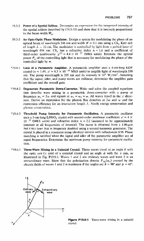
PROBLEMS 797
19.3-2
19.3-3
*19.4-1
*19.4-2
* 19.4-3
* 19.6-1
Power of a Spatial Soliton. Determine an expression for the integrated intensity of the spatial soliton described by (19.3-10) and show that it is inversely proportional to the beam width W,.
An Opto-Optic Phase Modulator. Design a system for modulating the phase of an optical beam of wavelength 546 nm and width W = 0.1 mm using a CS, Kerr cell of length L = 10 cm. The modulator is controlled by light from a pulsed laser of wavelength 694 nm. CS, has a refractive index n = 1.6 and a coefficient of third-order nonlinearity xc3) = . 4 4 x 1O-32 (MKS units). Estimate the optical power Pr of the controlling light that is necessary for modulating the phase of the controlled light by rr.
Gain of a Parametric Amplifier. A parametric amplifier uses a 4-cm-long KDP crystal (n = 1.49, d = 8.3 X 1O-24 MKS units) to amplify light of wavelength 550 nm. The pump wavelength is 335 nm and its intensity is lo6 W/cm2. Assuming that the signal, idler, and pump waves are collinear, determine the amplifier gain coefficient and the overall gain.
Degenerate Parametric Down-Converter. Write and solve the coupled equations that describe wave mixing in a parametric down-converter with a pump at frequency o3 = 20 and signals at w1 = w2 = cc). All waves travel in the z direc- tion. Derive an expression for the photon flux densities at 2w and w and the conversion efficiency for an interaction length L. Verify energy conservation and photon conservation.
Threshold Pump Intensity for Parametric Oscillation. A parametric oscillator uses a 5-cm-long LiNbO, crystal with second-order nonlinear coefficient d = 4 X 1O-23 (MKS u m s and refractive index n = 2.2 (assumed to be approximately ‘t ) constant at all frequencies of interest). The pump is obtained from a 1.06~pm Nd:YAG laser that is frequency doubled using a second-harmonic generator. The crystal is placed in a resonator using identical mirrors with reflectances 0.98. Phase matching is satisfied when the signal and idler of the parametric amplifier are of equal frequencies. Determine the minimum pump intensity for parametric oscilla- tion.
Three-Wave Mixing in a Uniaxial Crystal. Three waves travel at an angle 8 with the optic axis (z axis) of a uniaxial crystal and an angle 4 with the n axis, as illustrated in Fig. P19.6-1. Waves 1 and 2 are ordinary waves and wave 3 is an extraordinary wave. Show that the polarization density PNL(m3) created by the electric fields of waves 1 and 2 is maximum if the angles are 8 = 90” and 4 = 45”.
f Y
Figure P19.6-1 Three-wave mixing in a uniaxial crystal.

798 NONLINEAR OPTICS
*19.6-2 Phase Matching in a Degenerate Parametric Down-Converter. A degenerate para- metric down-converter uses a KDP crystal to down-convert light from 0.6 pm to 1.2 pm. If the two waves are collinear, what should the direction of propagation of the waves (in relation to the optic axis of the crystal) and their polarizations be so that the phase-matching condition is satisfied? KDP is a uniaxial crystal with the following refractive indices: at h, = 0.6 km, n, = 1.509 and n, = 1.468; at A, = 1.2 pm, n, = 1.490 and n, = 1.459.
* 19.6-3 Relation Between Nonlinear Optical Coefficients and Electra-Optic Coefficients. Show that the electro-optic coefficients are related to the coefficients of optical nonlinearity by rijk = -4~~dijk/~ii~jj and ~ijkr = - 12E,x~~~~/~ii~jj. These rela- tions are generalizations of (19.2-10) and (19.3-21, respectively. Hint: If two matrices A and B are related by B = A-‘, the incremental matrices AA and AB are related by AB = -A-’ AAA-l.