Embed Size (px)
Citation preview
Channelized and Electrical Interface Line Card Installation and Configuration
Document Order Number: DOC-7816417=
This hardware installation and configuration note contains instructions for installing, configuring, and troubleshooting channelized and electrical interface line cards on Cisco 12000 Series Routers.
ContentsThis installation and configuration note includes the following sections:
• Important Information, page 2
• Product Overview, page 5
• Preparing for Installation, page 12
• Removing and Installing a Line Card, page 14
• Line Card Cable-Management Bracket, page 17
• Cabling and Specifications, page 23
• Verifying and Troubleshooting the Line Card Installation, page 30
• Configuring and Troubleshooting Line Card Interfaces, page 40
• Line Card Memory, page 63
• Regulatory, Compliance, and Safety Information, page 74
• Obtaining Documentation, page 78
• Obtaining Technical Assistance, page 79
• Obtaining Additional Publications and Information, page 80
Corporate Headquarters:
Copyright © 2005 Cisco Systems, Inc. All rights reserved.
Cisco Systems, Inc., 170 West Tasman Drive, San Jose, CA 95134-1706 USA
Important Information
Important InformationThis section contains important information about the following topics:
• Channelized and Electrical Interface Line Card Product Numbers, page 2
• Router Hardware Installation, page 2
• Cisco IOS Software Release Requirements, page 3
• Hardware Revision Requirements, page 4
• AC-Input Power Supply Requirements, page 4
• Line Card Memory Options, page 5
• Related Documentation, page 5
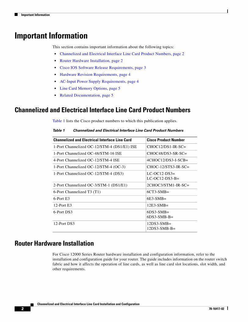
Channelized and Electrical Interface Line Card Product NumbersTable 1 lists the Cisco product numbers to which this publication applies.
Router Hardware Installation For Cisco 12000 Series Router hardware installation and configuration information, refer to the installation and configuration guide for your router. The guide includes information on the router switch fabric and how it affects the operation of line cards, as well as line card slot locations, slot width, and other requirements.
Table 1 Channelized and Electrical Interface Line Card Product Numbers
Channelized and Electrical Interface Line Card Cisco Product Number
1-Port Channelized OC-12/STM-4 (DS1/E1) ISE CHOC12/DS1-IR-SC=
1-Port Channelized OC-48/STM-16 ISE CHOC48/DS3-SR-SC=
4-Port Channelized OC-12/STM-4 ISE 4CHOC12/DS3-I-SCB=
1-Port Channelized OC-12/STM-4 (OC-3) CHOC-12/STS3-IR-SC=
1-Port Channelized OC-12/STM-4 (DS3) LC-OC12-DS3= LC-OC12-DS3-B=
2-Port Channelized OC-3/STM-1 (DS1/E1) 2CHOC3/STM1-IR-SC=
6-Port Channelized T3 (T1) 6CT3-SMB=
6-Port E3 6E3-SMB=
12-Port E3 12E3-SMB=
6-Port DS3 6DS3-SMB=6DS3-SMB-B=
12-Port DS3 12DS3-SMB=12DS3-SMB-B=
2Channelized and Electrical Interface Line Card Installation and Configuration
78-16417-02
Important Information
Supported Platforms
The channelized and electrical interface line cards are supported on all Cisco 12000 Series Routers.
Note To support the requirements of this line card, the Cisco 12000 Series Router must have at least one clock and scheduler card (CSC) installed. For additional information, refer to the installation and configuration guide for your Cisco 12000 Series Router.
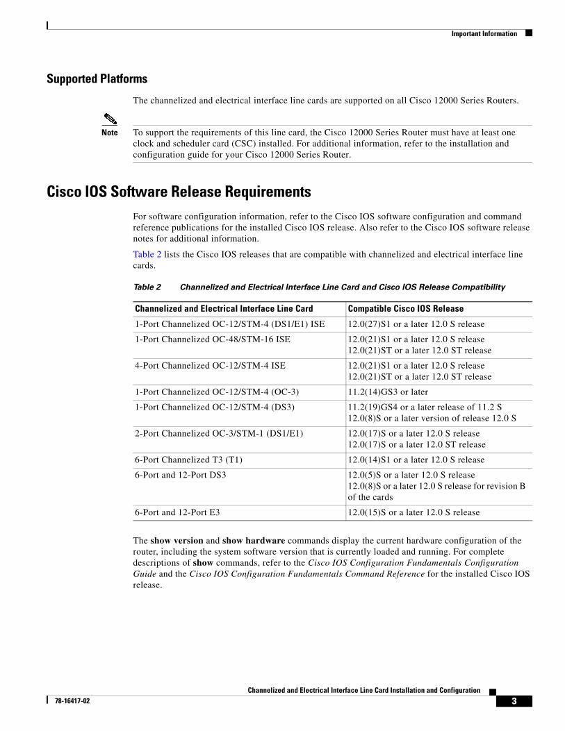
Cisco IOS Software Release RequirementsFor software configuration information, refer to the Cisco IOS software configuration and command reference publications for the installed Cisco IOS release. Also refer to the Cisco IOS software release notes for additional information.
Table 2 lists the Cisco IOS releases that are compatible with channelized and electrical interface line cards.
The show version and show hardware commands display the current hardware configuration of the router, including the system software version that is currently loaded and running. For complete descriptions of show commands, refer to the Cisco IOS Configuration Fundamentals Configuration Guide and the Cisco IOS Configuration Fundamentals Command Reference for the installed Cisco IOS release.
Table 2 Channelized and Electrical Interface Line Card and Cisco IOS Release Compatibility
Channelized and Electrical Interface Line Card Compatible Cisco IOS Release
1-Port Channelized OC-12/STM-4 (DS1/E1) ISE 12.0(27)S1 or a later 12.0 S release
1-Port Channelized OC-48/STM-16 ISE 12.0(21)S1 or a later 12.0 S release12.0(21)ST or a later 12.0 ST release
4-Port Channelized OC-12/STM-4 ISE 12.0(21)S1 or a later 12.0 S release12.0(21)ST or a later 12.0 ST release
1-Port Channelized OC-12/STM-4 (OC-3) 11.2(14)GS3 or later
1-Port Channelized OC-12/STM-4 (DS3) 11.2(19)GS4 or a later release of 11.2 S12.0(8)S or a later version of release 12.0 S
2-Port Channelized OC-3/STM-1 (DS1/E1) 12.0(17)S or a later 12.0 S release12.0(17)S or a later 12.0 ST release
6-Port Channelized T3 (T1) 12.0(14)S1 or a later 12.0 S release
6-Port and 12-Port DS3 12.0(5)S or a later 12.0 S release12.0(8)S or a later 12.0 S release for revision B of the cards
6-Port and 12-Port E3 12.0(15)S or a later 12.0 S release
3Channelized and Electrical Interface Line Card Installation and Configuration
78-16417-02
Important Information
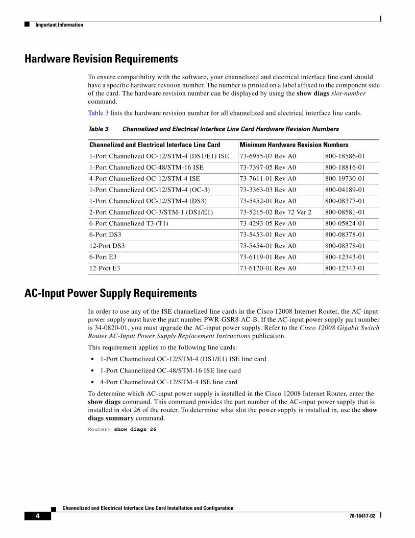
Hardware Revision RequirementsTo ensure compatibility with the software, your channelized and electrical interface line card should have a specific hardware revision number. The number is printed on a label affixed to the component side of the card. The hardware revision number can be displayed by using the show diags slot-number command.
Table 3 lists the hardware revision number for all channelized and electrical interface line cards.
AC-Input Power Supply RequirementsIn order to use any of the ISE channelized line cards in the Cisco 12008 Internet Router, the AC-input power supply must have the part number PWR-GSR8-AC-B. If the AC-input power supply part number is 34-0820-01, you must upgrade the AC-input power supply. Refer to the Cisco 12008 Gigabit Switch Router AC-Input Power Supply Replacement Instructions publication.
This requirement applies to the following line cards:
• 1-Port Channelized OC-12/STM-4 (DS1/E1) ISE line card
• 1-Port Channelized OC-48/STM-16 ISE line card
• 4-Port Channelized OC-12/STM-4 ISE line card
To determine which AC-input power supply is installed in the Cisco 12008 Internet Router, enter the show diags command. This command provides the part number of the AC-input power supply that is installed in slot 26 of the router. To determine what slot the power supply is installed in, use the show diags summary command.
Router> show diags 26
Table 3 Channelized and Electrical Interface Line Card Hardware Revision Numbers
Channelized and Electrical Interface Line Card Minimum Hardware Revision Numbers
1-Port Channelized OC-12/STM-4 (DS1/E1) ISE 73-6955-07 Rev A0 800-18586-01
1-Port Channelized OC-48/STM-16 ISE 73-7397-05 Rev A0 800-18816-01
4-Port Channelized OC-12/STM-4 ISE 73-7611-01 Rev A0 800-19730-01
1-Port Channelized OC-12/STM-4 (OC-3) 73-3363-03 Rev A0 800-04189-01
1-Port Channelized OC-12/STM-4 (DS3) 73-5452-01 Rev A0 800-08377-01
2-Port Channelized OC-3/STM-1 (DS1/E1) 73-5215-02 Rev 72 Ver 2 800-08581-01
6-Port Channelized T3 (T1) 73-4293-05 Rev A0 800-05824-01
6-Port DS3 73-5453-01 Rev A0 800-08378-01
12-Port DS3 73-5454-01 Rev A0 800-08378-01
6-Port E3 73-6119-01 Rev A0 800-12343-01
12-Port E3 73-6120-01 Rev A0 800-12343-01
4Channelized and Electrical Interface Line Card Installation and Configuration
78-16417-02
Product Overview
Line Card Memory OptionsThe channelized and electrical interface line card memory options vary by line card. See the “Line Card Memory” section on page 63 for more information.
Related DocumentationThis publication describes the basic installation and initial configuration of a channelized and electrical interface line card. For complete configuration information, refer to the following publications:
• Cisco IOS Software Configuration for the Cisco 12000 Series 1-Port Channelized OC-12c/STM-4 (DS1/E1) Line Card
• Installation and Configuration Guide for your router
• Software Configuration Guide for the Cisco 12000 Series Internet Router
• Cisco IOS Configuration Fundamentals Configuration Guide
• Cisco IOS Configuration Fundamentals Command Reference
• Cisco IOS Release 12.0S Release Notes for Cisco 12000 Series Internet Routers
• Field Diagnostics for the Cisco 12000 Series Internet Router
• Regulatory Compliance and Safety Information for Cisco 12000 Series Internet Routers
See the “Obtaining Documentation” section on page 78 for information on how to obtain these publications.
Product OverviewThis section includes product overview information for each channelized and electrical interface line card:
• 1-Port Channelized OC-12/STM-4 (DS1/E1) ISE Line Card Product Overview, page 5
• 1-Port Channelized OC-48/STM-16 ISE Line Card Product Overview, page 6
• 4-Port Channelized OC-12/STM-4 ISE Line Card Product Overview, page 7
• 1-Port Channelized OC-12/STM-4 (OC-3) Line Card Product Overview, page 7
• 1-Port Channelized OC-12/STM-4 (DS3) Line Card Product Overview, page 8
• 2-Port Channelized OC-3/STM-1 (DS1/E1) Line Card Product Overview, page 9
• 6-Port Channelized T3 (T1) Line Card Product Overview, page 9
• 6-Port and 12-Port DS3 Electrical Interface Line Card Product Overview, page 10
• 6-Port and 12-Port E3 Electrical Interface Line Card Product Overview, page 11
1-Port Channelized OC-12/STM-4 (DS1/E1) ISE Line Card Product OverviewThe 1-port channelized OC-12/STM-4 (DS1/E1) ISE line card provides Cisco 12000 Series Routers with a single OC-12c/STM-4c to DS1/E1 full-duplex, single-mode, intermediate-reach interface. Figure 1 shows the front view of this line card.
5Channelized and Electrical Interface Line Card Installation and Configuration
78-16417-02
Product Overview
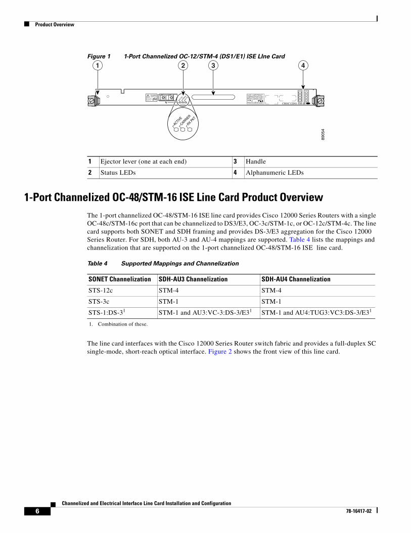
Figure 1 1-Port Channelized OC-12/STM-4 (DS1/E1) ISE LIne Card
1-Port Channelized OC-48/STM-16 ISE Line Card Product OverviewThe 1-port channelized OC-48/STM-16 ISE line card provides Cisco 12000 Series Routers with a single OC-48c/STM-16c port that can be channelized to DS3/E3, OC-3c/STM-1c, or OC-12c/STM-4c. The line card supports both SONET and SDH framing and provides DS-3/E3 aggregation for the Cisco 12000 Series Router. For SDH, both AU-3 and AU-4 mappings are supported. Table 4 lists the mappings and channelization that are supported on the 1-port channelized OC-48/STM-16 ISE line card.
The line card interfaces with the Cisco 12000 Series Router switch fabric and provides a full-duplex SC single-mode, short-reach optical interface. Figure 2 shows the front view of this line card.
ACTIVE
CARRIER
RX PKT
0 CHOC12DS1-SM-IR
8905
4
ACTIVE
CARRIER
RX PKT
CLEANCONNECTOR
WITH ALCOHOLWIPES BEFORECONNECTING
CLASS 1 LASER PRODUCTLASERPRODUKT DER KLASSE 1PRODUIT LASER DE CLASSE 1
PRODUCTO LASER DE CLASSE 1
1 2 3 4
1 Ejector lever (one at each end) 3 Handle
2 Status LEDs 4 Alphanumeric LEDs
Table 4 Supported Mappings and Channelization
SONET Channelization SDH-AU3 Channelization SDH-AU4 Channelization
STS-12c STM-4 STM-4
STS-3c STM-1 STM-1
STS-1:DS-31
1. Combination of these.
STM-1 and AU3:VC-3:DS-3/E31 STM-1 and AU4:TUG3:VC3:DS-3/E31
6Channelized and Electrical Interface Line Card Installation and Configuration
78-16417-02
Product Overview
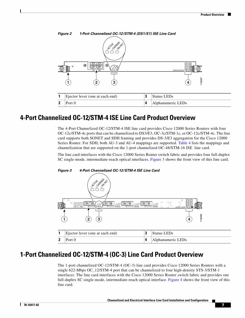
Figure 2 1-Port Channelized OC-12/STM-4 (DS1/E1) ISE Line Card
4-Port Channelized OC-12/STM-4 ISE Line Card Product OverviewThe 4-Port Channelized OC-12/STM-4 ISE line card provides Cisco 12000 Series Routers with four OC-12c/STM-4c ports that can be channelized to DS3/E3, OC-3c/STM-1c, or OC-12c/STM-4c. The line card supports both SONET and SDH framing and provides DS-3/E3 aggregation for the Cisco 12000 Series Router. For SDH, both AU-3 and AU-4 mappings are supported. Table 4 lists the mappings and channelization that are supported on the 1-port channelized OC-48/STM-16 ISE line card.
The line card interfaces with the Cisco 12000 Series Router switch fabric and provides four full-duplex SC single-mode, intermediate-reach optical interfaces. Figure 3 shows the front view of this line card.
Figure 3 4-Port Channelized OC-12/STM-4 ISE Line Card
1-Port Channelized OC-12/STM-4 (OC-3) Line Card Product OverviewThe 1-port channelized OC-12/STM-4 (OC-3) line card provides Cisco 12000 Series Routers with a single 622-Mbps OC_12/STM-4 port that can be channelized to four high-density STS-3/STM-1 interfaces. The line card interfaces with the Cisco 12000 Series Router switch fabric and provides one full-duplex SC single-mode, intermediate-reach optical interface. Figure 4 shows the front view of this line card.
ACTIVE
TX RXCARRIER
RX PKT
CHOC48X/DS3-SR-SC
4
1160
97
1 2 3
ACTIVE
CARRIER
RX PKT
1 Ejector lever (one at each end) 3 Status LEDs
2 Port 0 4 Alphanumeric LEDs
ACTIVE
CARRIER
RX PKT
0 3 4CHOC12/DS3-IR-SCACTIVE
CARRIER
RX PKT
2ACTIVE
CARRIER
RX PKT
1ACTIVE
CARRIER
RX PKTCLASS 1 LASER PRODUCTPRODUCTO LASER DE CLASSE 1PRODUIT LASER DE CLASSE 1LASERPRODUKT DER KLASSE 1
1160
98
1 2 3 4
ACTIVE
CARRIER
RX PKT
1 Ejector lever (one at each end) 3 Status LEDs
2 Port 0 4 Alphanumeric LEDs
7Channelized and Electrical Interface Line Card Installation and Configuration
78-16417-02
Product Overview
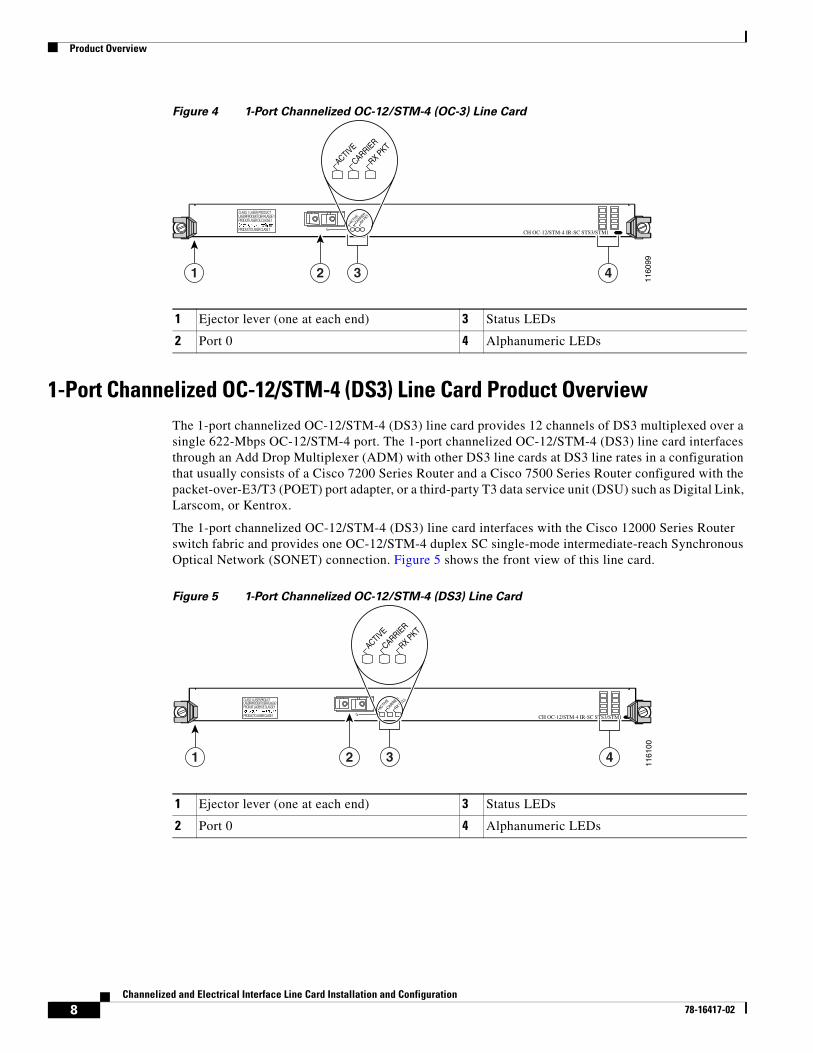
Figure 4 1-Port Channelized OC-12/STM-4 (OC-3) Line Card
1-Port Channelized OC-12/STM-4 (DS3) Line Card Product OverviewThe 1-port channelized OC-12/STM-4 (DS3) line card provides 12 channels of DS3 multiplexed over a single 622-Mbps OC-12/STM-4 port. The 1-port channelized OC-12/STM-4 (DS3) line card interfaces through an Add Drop Multiplexer (ADM) with other DS3 line cards at DS3 line rates in a configuration that usually consists of a Cisco 7200 Series Router and a Cisco 7500 Series Router configured with the packet-over-E3/T3 (POET) port adapter, or a third-party T3 data service unit (DSU) such as Digital Link, Larscom, or Kentrox.
The 1-port channelized OC-12/STM-4 (DS3) line card interfaces with the Cisco 12000 Series Router switch fabric and provides one OC-12/STM-4 duplex SC single-mode intermediate-reach Synchronous Optical Network (SONET) connection. Figure 5 shows the front view of this line card.
Figure 5 1-Port Channelized OC-12/STM-4 (DS3) Line Card
0
ACTIVE
CARRIER
RX PKT
CH OC-12/STM-4 IR-SC STS3/STM1
1160
99
1 2 3 4
ACTIVE
CARRIER
RX PKT
1 Ejector lever (one at each end) 3 Status LEDs
2 Port 0 4 Alphanumeric LEDs
ACTIVE
0
CARRIER
RX CELL
CH OC-12/STM-4 IR-SC STS3/STM1
1161
00
1 2 3 4
ACTIVE
CARRIER
RX PKT
1 Ejector lever (one at each end) 3 Status LEDs
2 Port 0 4 Alphanumeric LEDs
8Channelized and Electrical Interface Line Card Installation and Configuration
78-16417-02
Product Overview
2-Port Channelized OC-3/STM-1 (DS1/E1) Line Card Product OverviewThe 2-port channelized OC-3/STM-1 (DS1/E1) line card provides E1/DS1 aggregation for the Cisco 12000 Series Router. The 2-port channelized OC-3/STM-1 (DS1/E1) line card interfaces with the router switch fabric and provides two OC-3/STM-1 duplex SC single-mode intermediate-reach optical interfaces.
When configured for operation in a Synchronous Digital Hierarchy (SDH) environment, each STM-1 port is capable of supporting channelization into either 63 independent E1s through VC-12 ETSI mapping, or 84 J1 (Japanese T1 equivalent) channels through VC-11 ANSI mapping.
When configured for operation in a Synchronous Optical Network (SONET) environment, each OC-3 port is capable of supporting channelization into 84 independent DS1 channels using VT1.5 mapping or CT3 mapping into STS-1.
Fractional E1 and individual 64-kbps channels can also be configured, up to the limit of 105 channel definitions per STM-1 (35 per TUG-3). Fractional T1 and individual DS0 channels can also be configured, up to the limit of 35 channel definitions per STS-1 (210 per line card).
Each 2-port channelized OC-3/STM-1 (DS1/E1) line card supports up to 126 E1s when configured for SDH operation, 168 DS1 connections when configured for SONET operation, or any combination of 64 kbps/DS0, fractional E1/T1, or E1/T1 interface definitions, up to the limit of 210 per line card.
Figure 6 shows the front view of this line card.
Figure 6 2-Port Channelized OC-3/STM-1 (DS1/E1) Line Card
6-Port Channelized T3 (T1) Line Card Product OverviewThe 6-port channelized T3 (T1) line card performs High-Level Data Link Control (HDLC) encapsulation and de-encapsulation functions, and all other necessary functions including timing, signaling, and framing in compliance with DS1 and DS3 specifications.
Figure 7 shows the front view of this line card.
1161
01
1
ACTIVE
CARRIER
0 1
2CHOC3/STM1-IR-SCACTIVE
CARRIERCLASS 1 LASER PRODUCTPRODUCTO LASER DE CLASSE 1PRODUIT LASER DE CLASSE 1LASERPRODUKT DER KLASSE 1
CLEANCONNECTOR
WITH ALCOHOLWIPES BEFORECONNECTING
ACTIVE
CARRIER
2 3 4
1 Ejector lever (one at each end) 3 Status LEDs
2 Port 0 4 Alphanumeric LEDs
9Channelized and Electrical Interface Line Card Installation and Configuration
78-16417-02

Product Overview
Figure 7 6-Port Channelized T3 (T1) Line Card
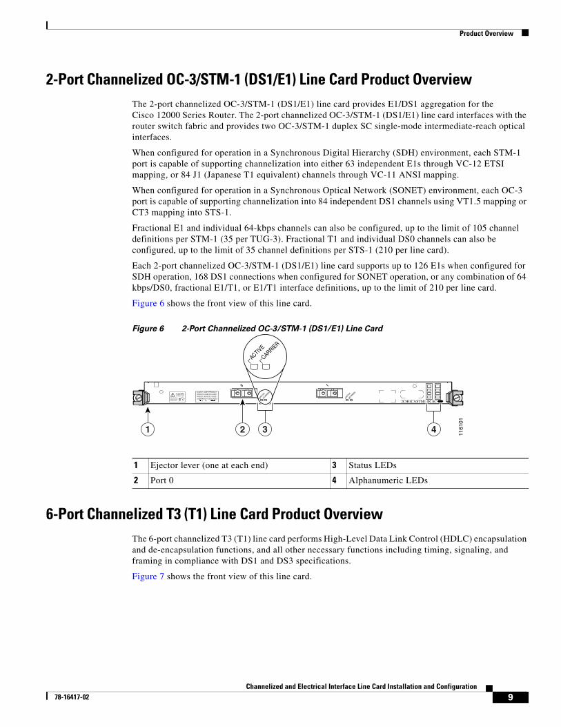
6-Port and 12-Port DS3 Electrical Interface Line Card Product OverviewThe 6-port and 12-port DS3 electrical interface line cards consist of high-density DS3 service through six T3 or twelve T3 interfaces.
The 6-port line card is a partially depopulated version of the 12-port line card. The 6-port line card consists of a total of 12 connectors. A single port consists of one coaxial connector for receiving (RX) and one coaxial connector for transmitting (TX). The ports on the 6-port line card are numbered 0 to 5.
The 12-port line card consists of a total of 24 connectors. A single port consists of one coaxial connector for receiving (RX) and one coaxial connector for transmitting (TX). The ports on the 12-port line card are numbered 0 to 11.
Figure 8 shows the front view of these line cards.
6CT3-SMBDOWN
LOOP RA LA
CDHNT CD
TX 5 RXTX 4 RXTX 3 RXTX 2 RXTX 1 RXTX 0 RX
1161
02
1
DOWN
LOOP RA LA
CDHNT CD
2 3 4 5
7 8
6
1 Ejector lever (one at each end) 5 Alphanumeric LEDs
2 LED legend 6 Green
3 Port 0 7 Alternates green/yellow
4 Status LEDs 8 Yellow
10Channelized and Electrical Interface Line Card Installation and Configuration
78-16417-02
Product Overview
Figure 8 6-Port and 12-Port DS3 Line Cards
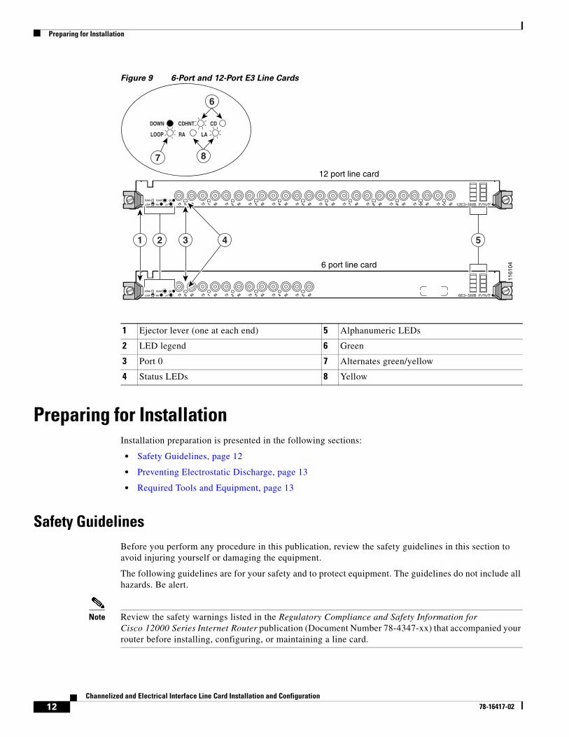
6-Port and 12-Port E3 Electrical Interface Line Card Product OverviewThe 6-port and 12-port E3 electrical interface line cards consist of high-density E3 service through six E3 or twelve E3 interfaces.
The 6-port line card is a partially depopulated version of the 12-port line card. The 6-port line card consists of a total of 12 connectors. A single port consists of one coaxial connector for receiving (RX) and one coaxial connector for transmitting (TX). The ports on the 6-port line card are numbered 0 to 5.
The 12-port line card consists of a total of 24 connectors. A single port consists of one coaxial connector for receiving (RX) and one coaxial connector for transmitting (TX). The ports on the 12-port line card are numbered 0 to 11.
Figure 9 shows the front view of these line cards.
DOWN
LOOP RA LA
CDHNT CD
TX 5 RXTX 4 RXTX 3 RXTX 2 RXTX 1 RXTX 0 RX 6DS3–SMB P/H/F
DOWN
LOOP RA LA
CDHNT CD
7 8
6
DOWN
LOOP RA LA
CDHNT CD
TX 11 RXTX 10 RXTX 9 RXTX 8 RXTX 7 RXTX 6 RXTX 5 RXTX 4 RXTX 3 RXTX 2 RXTX 1 RXTX 0 RX 12DS3–SMB P/H/F
6 port line card
12 port line card
1161
03
1 2 3 4 5
1 Ejector lever (one at each end) 5 Alphanumeric LEDs
2 LED legend 6 Green
3 Port 0 7 Alternates green/yellow
4 Status LEDs 8 Yellow
11Channelized and Electrical Interface Line Card Installation and Configuration
78-16417-02
Preparing for Installation
Figure 9 6-Port and 12-Port E3 Line Cards
Preparing for InstallationInstallation preparation is presented in the following sections:
• Safety Guidelines, page 12
• Preventing Electrostatic Discharge, page 13
• Required Tools and Equipment, page 13
Safety GuidelinesBefore you perform any procedure in this publication, review the safety guidelines in this section to avoid injuring yourself or damaging the equipment.
The following guidelines are for your safety and to protect equipment. The guidelines do not include all hazards. Be alert.
Note Review the safety warnings listed in the Regulatory Compliance and Safety Information for Cisco 12000 Series Internet Router publication (Document Number 78-4347-xx) that accompanied your router before installing, configuring, or maintaining a line card.
TX 5 RXTX 4 RXTX 3 RXTX 2 RXTX 1 RXTX 0 RX 6E3–SMB P/H/FDOWN
LOOP RA LA
CDHNT CD
DOWN
LOOP RA LA
CDHNT CD
7 8
6
TX 11 RXTX 10 RXTX 9 RXTX 8 RXTX 7 RXTX 6 RXTX 5 RXTX 4 RXTX 3 RXTX 2 RXTX 1 RXTX 0 RX 12E3–SMB P/H/FDOWN
LOOP RA LA
CDHNT CD
6 port line card
12 port line card
1161
04
1 2 3 4 5
1 Ejector lever (one at each end) 5 Alphanumeric LEDs
2 LED legend 6 Green
3 Port 0 7 Alternates green/yellow
4 Status LEDs 8 Yellow
12Channelized and Electrical Interface Line Card Installation and Configuration
78-16417-02
Preparing for Installation
• Keep the work area clear and dust free during and after installation. Do not allow dirt or debris to enter into any laser-based components.
• Do not wear loose clothing, jewelry, or other items that could get caught in the router while working with line cards.
• Cisco equipment operates safely when it is used in accordance with its specifications and product usage instructions.
See the “Line Card Interface Cables” section on page 25 for information on interface cables.
Preventing Electrostatic DischargeElectrostatic discharge (ESD) damage, which can occur when electronic cards or components are improperly handled, results in complete or intermittent failures. Electromagnetic interference (EMI) shielding is an integral component of the line card. Cisco recommends using an ESD-preventive strap whenever you are handling network equipment or one of its components.
The following are guidelines for preventing ESD damage:
• Always use an ESD-preventive wrist or ankle strap and ensure that it makes good skin contact. Connect the equipment end of the connection cord to an ESD connection socket on the router or to bare metal on the chassis.
• Handle channelized and electrical interface line cards by the captive installation screws, the provided handle, ejector levers, or the line card metal carrier only; avoid touching the board or connector pins.
• Place removed channelized and electrical interface line cards board-side-up on an antistatic surface or in a static shielding bag. If you plan to return the component to the factory, immediately place it in a static shielding bag.
• Avoid contact between the channelized and electrical interface line cards and clothing. The wrist strap only protects the board from ESD voltages on the body; ESD voltages on clothing can still cause damage.
Warning For safety, periodically check the resistance value of the ESD strap. The measurement should be between 1 and 10 megohms.
Required Tools and EquipmentYou need the following tools and parts to remove and install channelized and electrical interface line cards:
• Flat-blade or Phillips screwdriver
• ESD-preventive wrist or ankle strap and instructions
• Interface cables to connect the channelized and electrical interface line card with another router or switch
13Channelized and Electrical Interface Line Card Installation and Configuration
78-16417-02
Removing and Installing a Line Card
Removing and Installing a Line CardThe following sections describe the procedures for removing and installing line cards:
• Guidelines for Line Card Removal and Installation, page 14
• Removing a Line Card, page 15
• Installing a Line Card, page 16
Note Some of the procedures in the following sections use illustrations of a Cisco 12012 Internet Router to support the descriptions of removing and installing line cards. Although the card cages of Cisco 12000 Series Routers differ, the designated use of slots and the process of installing and removing a line card are basically the same. Therefore, separate procedures and illustrations are not included in this publication.
Guidelines for Line Card Removal and InstallationGuidelines for line card removal and installation include the following:
• Online insertion and removal (OIR) is supported, enabling you to remove and install line cards while the router is operating. OIR is seamless to users on the network, maintains all routing information, and ensures session preservation.
Note With OIR, notifying the software or resetting the power is not required. However, you have the option of using the shutdown command before removing a line card.
• After you reinstall a line card, the router automatically downloads the necessary software from the route processor (RP). Next, the router brings online only those interfaces that match the current configuration and were previously configured as administratively up. You must configure all others with the configure command.
Caution The router may indicate a hardware failure if you do not follow proper procedures. Remove or insert only one line card at a time. Allow at least 15 seconds for the router to complete the preceding tasks before removing or inserting another line card.
After removing and inserting a line card into the same slot, allow at least 60 seconds before removing or inserting another line card.
• Line cards have two ejector levers to release the card from its backplane connector. Use the levers when you are removing the line card and to seat the line card firmly in its backplane connector when you are installing the line card. The ejector levers align and seat the card connectors in the backplane.
14Channelized and Electrical Interface Line Card Installation and Configuration
78-16417-02
Removing and Installing a Line Card
Caution When you remove a line card, always use the ejector levers to ensure that the connector pins disconnect from the backplane in the sequence expected by the router. Any card that is only partially connected to the backplane can halt the router.
When you install a line card, always use the ejector levers to ensure that the card is correctly aligned with the backplane connector; the connector pins should make contact with the backplane in the correct order, indicating that the card is fully seated in the backplane. If a card is only partially seated in the backplane, the router will hang and subsequently crash.
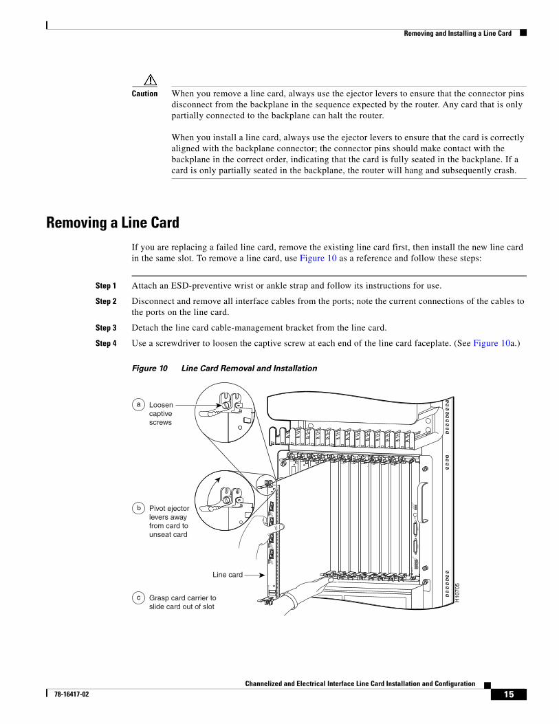
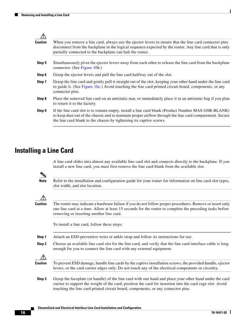
Removing a Line CardIf you are replacing a failed line card, remove the existing line card first, then install the new line card in the same slot. To remove a line card, use Figure 10 as a reference and follow these steps:
Step 1 Attach an ESD-preventive wrist or ankle strap and follow its instructions for use.
Step 2 Disconnect and remove all interface cables from the ports; note the current connections of the cables to the ports on the line card.
Step 3 Detach the line card cable-management bracket from the line card.
Step 4 Use a screwdriver to loosen the captive screw at each end of the line card faceplate. (See Figure 10a.)
Figure 10 Line Card Removal and Installation
SLOT-0
GIG
AB
IT R
OU
TE
PRO
CE
SSOR
SLOT-1COLL
LINKTX
RXRJ-45
MII
RESET
AUX
CONSOLE
EJECT
ACTIVE
0
CARRIER
RX PKT
ACTIVE
1
CARRIER
RX PKT
ACTIVE
2
CARRIER
RX PKT
ACTIVE
3
CARRIER
RX PKT
Q O
C-3/ST
M-PO
S
ACTIVE
0
CARRIER
RX CELL
OC
-12/STM
-4 AT
M
OC
-12/STM
-4 POS
ACTIVE
0
CARRIER
RX CELL
ACO/LT
ALARM
1ALAR
M 2
AL
AR
M
CSC
0
FAIL
10
12
ENABLED
CRITICALMAJORMINOR
SFC
ACTIVE
0
CARRIER
RX PKT
ACTIVE
1
CARRIER
RX PKT
ACTIVE
2
CARRIER
RX PKT
ACTIVE
3
CARRIER
RX PKT
Q O
C-3/ST
M-PO
S
H10
705
Loosencaptivescrews
Line card
Pivot ejectorlevers awayfrom card tounseat card
Grasp card carrier toslide card out of slot
a
c
b
15Channelized and Electrical Interface Line Card Installation and Configuration
78-16417-02
Removing and Installing a Line Card
Caution When you remove a line card, always use the ejector levers to ensure that the line card connector pins disconnect from the backplane in the logical sequence expected by the router. Any line card that is only partially connected to the backplane can halt the router.
Step 5 Simultaneously pivot the ejector levers away from each other to release the line card from the backplane connector. (See Figure 10b.)
Step 6 Grasp the ejector levers and pull the line card halfway out of the slot.
Step 7 Grasp the line card and gently pull it straight out of the slot, keeping your other hand under the line card to guide it. (See Figure 10c.) Avoid touching the line card printed circuit board, components, or any connector pins.
Step 8 Place the removed line card on an antistatic mat, or immediately place it in an antistatic bag if you plan to return it to the factory.
Step 9 If the line card slot is to remain empty, install a line card blank (Product Number MAS-GSR-BLANK) to keep dust out of the chassis and to maintain proper airflow through the line card compartment. Secure the line card blank to the chassis by tightening its captive screws.
Installing a Line CardA line card slides into almost any available line card slot and connects directly to the backplane. If you install a new line card, you must first remove the line card blank from the available slot.
Note Refer to the installation and configuration guide for your router for information on line card slot types, slot width, and slot location.
Caution The router may indicate a hardware failure if you do not follow proper procedures. Remove or insert only one line card at a time. Allow at least 15 seconds for the router to complete the preceding tasks before removing or inserting another line card.
To install a line card, follow these steps:
Step 1 Attach an ESD-preventive wrist or ankle strap and follow its instructions for use.
Step 2 Choose an available line card slot for the line card, and verify that the line card interface cable is long enough for you to connect the line card with any external equipment.
Caution To prevent ESD damage, handle line cards by the captive installation screws, the provided handle, ejector levers, or the card carrier edges only. Do not touch any of the electrical components or circuitry.
Step 3 Grasp the faceplate (or handle) of the line card with one hand and place your other hand under the card carrier to support the weight of the card; position the card for insertion into the card cage slot. Avoid touching the line card printed circuit board, components, or any connector pins.
16Channelized and Electrical Interface Line Card Installation and Configuration
78-16417-02
Line Card Cable-Management Bracket
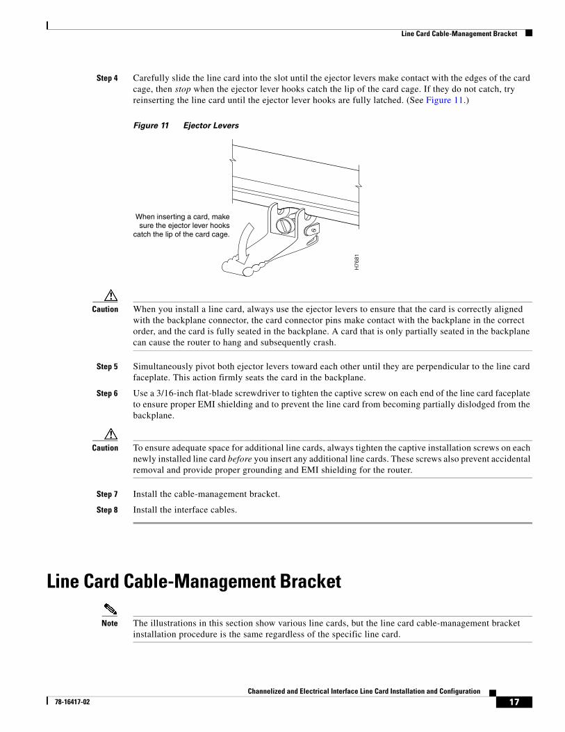
Step 4 Carefully slide the line card into the slot until the ejector levers make contact with the edges of the card cage, then stop when the ejector lever hooks catch the lip of the card cage. If they do not catch, try reinserting the line card until the ejector lever hooks are fully latched. (See Figure 11.)
Figure 11 Ejector Levers
Caution When you install a line card, always use the ejector levers to ensure that the card is correctly aligned with the backplane connector, the card connector pins make contact with the backplane in the correct order, and the card is fully seated in the backplane. A card that is only partially seated in the backplane can cause the router to hang and subsequently crash.
Step 5 Simultaneously pivot both ejector levers toward each other until they are perpendicular to the line card faceplate. This action firmly seats the card in the backplane.
Step 6 Use a 3/16-inch flat-blade screwdriver to tighten the captive screw on each end of the line card faceplate to ensure proper EMI shielding and to prevent the line card from becoming partially dislodged from the backplane.
Caution To ensure adequate space for additional line cards, always tighten the captive installation screws on each newly installed line card before you insert any additional line cards. These screws also prevent accidental removal and provide proper grounding and EMI shielding for the router.
Step 7 Install the cable-management bracket.
Step 8 Install the interface cables.
Line Card Cable-Management Bracket
Note The illustrations in this section show various line cards, but the line card cable-management bracket installation procedure is the same regardless of the specific line card.
When inserting a card, makesure the ejector lever hooks
catch the lip of the card cage.
H76
81
17Channelized and Electrical Interface Line Card Installation and Configuration
78-16417-02
Line Card Cable-Management Bracket
Cisco 12000 Series Routers include a cable-management system that organizes the interface cables entering and exiting the router, keeping them out of the way and free of sharp bends.
Caution Excessive bending of interface cables can damage the cables.
The cable-management system consists of two separate components:
1. A cable-management tray that is mounted on the chassis. Refer to the appropriate Cisco 12000 Series Router installation and configuration guide for more information on the cable-management tray.
2. A cable-management bracket that attaches to a line card.
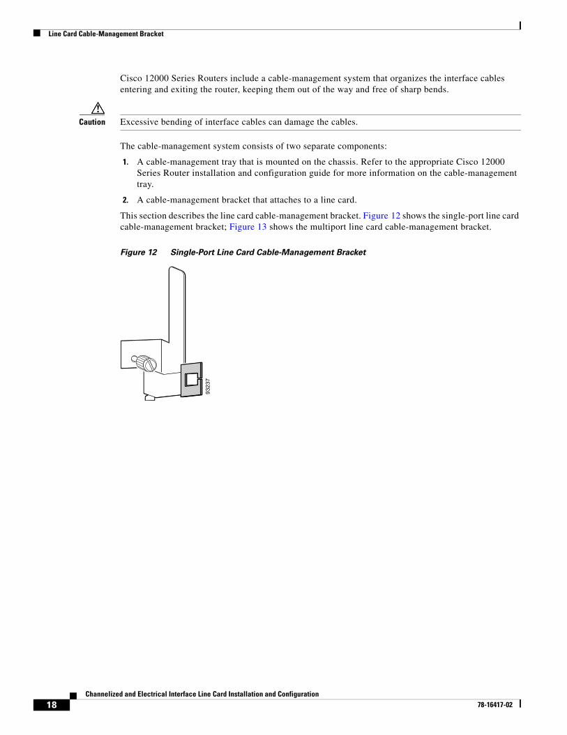
This section describes the line card cable-management bracket. Figure 12 shows the single-port line card cable-management bracket; Figure 13 shows the multiport line card cable-management bracket.
Figure 12 Single-Port Line Card Cable-Management Bracket
9323
7
18Channelized and Electrical Interface Line Card Installation and Configuration
78-16417-02
Line Card Cable-Management Bracket
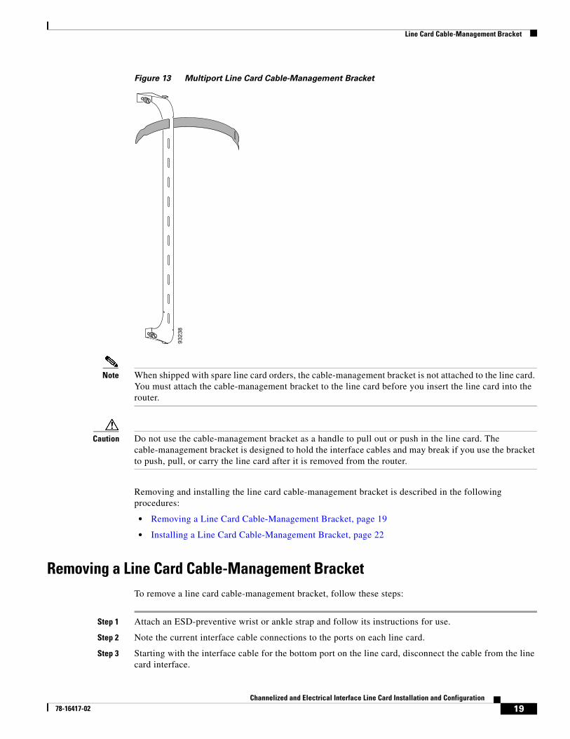
Figure 13 Multiport Line Card Cable-Management Bracket
Note When shipped with spare line card orders, the cable-management bracket is not attached to the line card. You must attach the cable-management bracket to the line card before you insert the line card into the router.
Caution Do not use the cable-management bracket as a handle to pull out or push in the line card. The cable-management bracket is designed to hold the interface cables and may break if you use the bracket to push, pull, or carry the line card after it is removed from the router.
Removing and installing the line card cable-management bracket is described in the following procedures:
• Removing a Line Card Cable-Management Bracket, page 19
• Installing a Line Card Cable-Management Bracket, page 22
Removing a Line Card Cable-Management BracketTo remove a line card cable-management bracket, follow these steps:
Step 1 Attach an ESD-preventive wrist or ankle strap and follow its instructions for use.
Step 2 Note the current interface cable connections to the ports on each line card.
Step 3 Starting with the interface cable for the bottom port on the line card, disconnect the cable from the line card interface.
9323
8
19Channelized and Electrical Interface Line Card Installation and Configuration
78-16417-02
Line Card Cable-Management Bracket
Note It is not necessary to remove the interface cables from the line card cable-management bracket. The bracket (with attached cables) can be hooked to the cable-management tray or a bracket on the chassis until a new line card is installed.
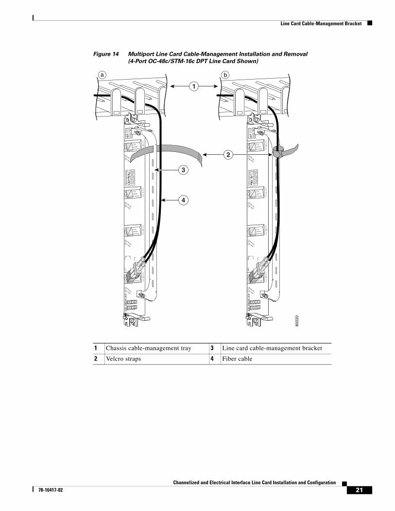
Step 4 For multiport line card cable-management brackets, proceed upward and remove the interface from the Velcro strap on the end of the cable standoff. (See Figure 14.)
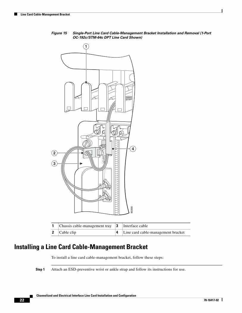
For single-port line card cable-management brackets, carefully remove the interface cable from the cable clip. (See Figure 15.) Avoid any kinks or sharp bends in the cable.
Step 5 Repeat Step 3 and Step 4 for all remaining interface cables, then proceed to Step 6.
Step 6 For multiport line card cable-management brackets, loosen the captive installation screw at each end of the cable-management bracket and remove the bracket from the line card.
For single-port line card cable-management brackets, loosen the captive installation screw on the cable-management bracket and remove the bracket from the line card.
20Channelized and Electrical Interface Line Card Installation and Configuration
78-16417-02
Line Card Cable-Management Bracket
Figure 14 Multiport Line Card Cable-Management Installation and Removal
(4-Port OC-48c/STM-16c DPT Line Card Shown)
1 Chassis cable-management tray 3 Line card cable-management bracket
2 Velcro straps 4 Fiber cable
ACTIVE
CARRIER
RX PACKET
ACTIVE
CARRIER
RX PACKET
ACTIVE
CARRIER
RX PACKET
ACTIVE
CARRIER
RX PACKET
WRAP
01
PASS THRU
WRAP
PASS THRU
2
WRAP
PASS THRU
3
WRAP
PASS THRU
CLASS 1 LASER PRODUCTLASERPRODUKT DER KLASSE 1PRODUIT LASER DE CLASSE 1
PRODUCTO LASER DE CLASSE 14O
C48/SR
P-SFP
CLE
AN
CO
NN
ECTO
RW
ITH
ALC
OH
OL
WIP
ES
BE
FO
RE
CO
NN
EC
TIN
G
8022
0
ACTIVE
CARRIER
RX PACKET
ACTIVE
CARRIER
RX PACKET
ACTIVE
CARRIER
RX PACKET
ACTIVE
CARRIER
RX PACKET
WRAP
01
PASS THRU
WRAP
PASS THRU
2
WRAP
PASS THRU
3
WRAP
PASS THRU
CLASS 1 LASER PRODUCTLASERPRODUKT DER KLASSE 1PRODUIT LASER DE CLASSE 1
PRODUCTO LASER DE CLASSE 14O
C48/SR
P-SFP
CLE
AN
CO
NN
ECTO
RW
ITH
ALC
OH
OL
WIP
ES
BE
FO
RE
CO
NN
EC
TIN
G
a b
4
1
2
3
21Channelized and Electrical Interface Line Card Installation and Configuration
78-16417-02
Line Card Cable-Management Bracket
Figure 15 Single-Port Line Card Cable-Management Bracket Installation and Removal (1-Port
OC-192c/STM-64c DPT Line Card Shown)
Installing a Line Card Cable-Management BracketTo install a line card cable-management bracket, follow these steps:
Step 1 Attach an ESD-preventive wrist or ankle strap and follow its instructions for use.
1 Chassis cable-management tray 3 Interface cable
2 Cable clip 4 Line card cable-management bracket
TX
RX
TXR
X
8030
0
4
1
3
2
22Channelized and Electrical Interface Line Card Installation and Configuration
78-16417-02
Cabling and Specifications
Step 2 Attach the line card cable-management bracket to the line card as follows:
a. Position the cable-management bracket over the front of the line card faceplate.
b. Insert and tighten the captive screw(s) to secure the bracket to the line card.
c. Starting with the bottom port on the line card, connect each interface cable to the intended port.
Step 3 For multiport line card cable-management brackets, carefully wrap the cables with the supplied Velcro strap. (See Figure 14.)
For single-port line card cable-management brackets, carefully press the interface cable onto the cable clip. (See Figure 15.) Avoid any kinks or sharp bends in the cable.
For information on disconnecting and connecting interface cables, see the “Line Card Interface Cables” section on page 25.
Cabling and SpecificationsThe following sections provide specifications for the channelized and electrical interface line card:
• Power Budget and Signal Specifications, page 23
• Line Card Interface Cables, page 25
Power Budget and Signal SpecificationsThe SONET specification for fiber-optic transmission defines two types of fiber: single-mode and multimode. Signals can travel farther through single-mode fiber than through multimode fiber.
The maximum distance for installations is determined by the amount of light loss in the fiber path. If your environment requires the signal to travel close to the typical maximum distance, you should use an optical time domain reflectometer (OTDR) to measure the power loss.
The following sections describe the power budget and signal specifications for the optics used in the channelized line cards:
• 1-Port Channelized OC-12/STM-4 (DS1/E1) ISE Line Card Power Specifications, page 23
• 1-Port Channelized OC-48/STM-16 ISE Line Card Power Specifications, page 24
• 4-Port Channelized OC-12/STM-4 ISE Line Card Power Specifications, page 24
• 1-Port Channelized OC-12/STM-4 (OC-3) Line Card Power Specifications, page 24
• 1-Port Channelized OC-12/STM-4 (DS3) Line Card Power Specifications, page 25
• 2-Port Channelized OC-3/STM-1 (DS1/E1) Line Card Power Specifications, page 25
1-Port Channelized OC-12/STM-4 (DS1/E1) ISE Line Card Power Specifications
The 1-port channelized OC-12/STM-4 (DS1/E1) ISE line card is only available in a single-mode, intermediate-reach configuration providing a full-duplex 622.08-Mbps 1310-nm laser-based SONET-compliant interface. The transmitter section of this device uses a laser with full IEC 825 and
23Channelized and Electrical Interface Line Card Installation and Configuration
78-16417-02
Cabling and Specifications
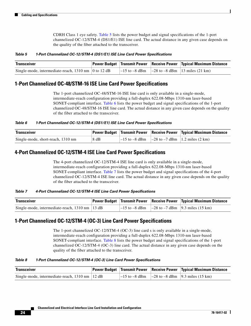
CDRH Class 1 eye safety. Table 5 lists the power budget and signal specifications of the 1-port channelized OC-12/STM-4 (DS1/E1) ISE line card. The actual distance in any given case depends on the quality of the fiber attached to the transceiver.
1-Port Channelized OC-48/STM-16 ISE Line Card Power Specifications
The 1-port channelized OC-48/STM-16 ISE line card is only available in a single-mode, intermediate-reach configuration providing a full-duplex 622.08-Mbps 1310-nm laser-based SONET-compliant interface. Table 6 lists the power budget and signal specifications of the 1-port channelized OC-48/STM-16 ISE line card. The actual distance in any given case depends on the quality of the fiber attached to the transceiver.
4-Port Channelized OC-12/STM-4 ISE Line Card Power Specifications
The 4-port channelized OC-12/STM-4 ISE line card is only available in a single-mode, intermediate-reach configuration providing a full-duplex 622.08-Mbps 1310-nm laser-based SONET-compliant interface. Table 7 lists the power budget and signal specifications of the 4-port channelized OC-12/STM-4 ISE line card. The actual distance in any given case depends on the quality of the fiber attached to the transceiver.
1-Port Channelized OC-12/STM-4 (OC-3) Line Card Power Specifications
The 1-port channelized OC-12/STM-4 (OC-3) line card s is only available in a single-mode, intermediate-reach configuration providing a full-duplex 622.08-Mbps 1310-nm laser-based SONET-compliant interface. Table 8 lists the power budget and signal specifications of the 1-port channelized OC-12/STM-4 (OC-3) line card. The actual distance in any given case depends on the quality of the fiber attached to the transceiver.
Table 5 1-Port Channelized OC-12/STM-4 (DS1/E1) ISE Line Card Power Specifications
Transceiver Power Budget Transmit Power Receive Power Typical Maximum Distance
Single-mode, intermediate-reach, 1310 nm 0 to 12 dB –15 to –8 dBm –28 to –8 dBm 13 miles (21 km)
Table 6 1-Port Channelized OC-12/STM-4 (DS1/E1) ISE Line Card Power Specifications
Transceiver Power Budget Transmit Power Receive Power Typical Maximum Distance
Single-mode, short-reach, 1310 nm 8 dB –15 to –8 dBm –28 to –7 dBm 1.2 miles (2 km)
Table 7 4-Port Channelized OC-12/STM-4 ISE Line Card Power Specifications
Transceiver Power Budget Transmit Power Receive Power Typical Maximum Distance
Single-mode, intermediate-reach, 1310 nm 13 dB –15 to –8 dBm –28 to –7 dBm 9.3 miles (15 km)
Table 8 1-Port Channelized OC-12/STM-4 (OC-3) Line Card Power Specifications
Transceiver Power Budget Transmit Power Receive Power Typical Maximum Distance
Single-mode, intermediate-reach, 1310 nm 12 dB –15 to –8 dBm –28 to –8 dBm 9.3 miles (15 km)
24Channelized and Electrical Interface Line Card Installation and Configuration
78-16417-02
Cabling and Specifications
1-Port Channelized OC-12/STM-4 (DS3) Line Card Power Specifications
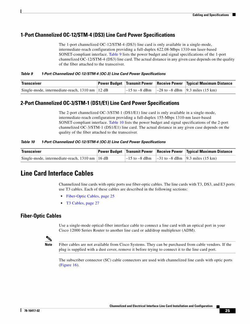
The 1-port channelized OC-12/STM-4 (DS3) line card is only available in a single-mode, intermediate-reach configuration providing a full-duplex 622.08-Mbps 1310-nm laser-based SONET-compliant interface. Table 9 lists the power budget and signal specifications of the 1-port channelized OC-12/STM-4 (DS3) line card. The actual distance in any given case depends on the quality of the fiber attached to the transceiver.
2-Port Channelized OC-3/STM-1 (DS1/E1) Line Card Power Specifications
The 2-port channelized OC-3/STM-1 (DS1/E1) line card is only available in a single-mode, intermediate-reach configuration providing a full-duplex 155-Mbps 1310-nm laser-based SONET-compliant interface. Table 10 lists the power budget and signal specifications of the 2-port channelized OC-3/STM-1 (DS1/E1) line card. The actual distance in any given case depends on the quality of the fiber attached to the transceiver.
Line Card Interface CablesChannelized line cards with optic ports use fiber-optic cables. The line cards with T3, DS3, and E3 ports use T3 cables. Each of these cables are described in the following sections:
• Fiber-Optic Cables, page 25
• T3 Cables, page 27
Fiber-Optic Cables
Use a single-mode optical-fiber interface cable to connect a line card with an optical port in your Cisco 12000 Series Router to another line card or add/drop multiplexer (ADM).
Note Fiber cables are not available from Cisco Systems. They can be purchased from cable vendors. If the plug is supplied with a dust cover, remove it before trying to connect it to the line card port.
The subscriber connector (SC) cable connectors are used with channelized line cards with optic ports (Figure 16).
Table 9 1-Port Channelized OC-12/STM-4 (OC-3) Line Card Power Specifications
Transceiver Power Budget Transmit Power Receive Power Typical Maximum Distance
Single-mode, intermediate-reach, 1310 nm 12 dB –15 to –8 dBm –28 to –8 dBm 9.3 miles (15 km)
Table 10 1-Port Channelized OC-12/STM-4 (OC-3) Line Card Power Specifications
Transceiver Power Budget Transmit Power Receive Power Typical Maximum Distance
Single-mode, intermediate-reach, 1310 nm 16 dB –15 to –8 dBm –31 to –8 dBm 9.3 miles (15 km)
25Channelized and Electrical Interface Line Card Installation and Configuration
78-16417-02
Cabling and Specifications
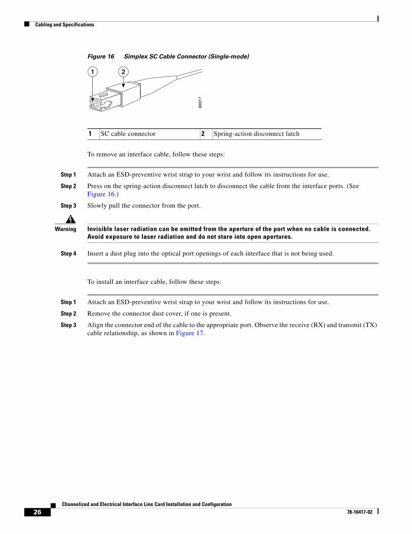
Figure 16 Simplex SC Cable Connector (Single-mode)
To remove an interface cable, follow these steps:
Step 1 Attach an ESD-preventive wrist strap to your wrist and follow its instructions for use.
Step 2 Press on the spring-action disconnect latch to disconnect the cable from the interface ports. (See Figure 16.)
Step 3 Slowly pull the connector from the port.
Warning Invisible laser radiation can be emitted from the aperture of the port when no cable is connected. Avoid exposure to laser radiation and do not stare into open apertures.
Step 4 Insert a dust plug into the optical port openings of each interface that is not being used.
To install an interface cable, follow these steps:
Step 1 Attach an ESD-preventive wrist strap to your wrist and follow its instructions for use.
Step 2 Remove the connector dust cover, if one is present.
Step 3 Align the connector end of the cable to the appropriate port. Observe the receive (RX) and transmit (TX) cable relationship, as shown in Figure 17.
1 SC cable connector 2 Spring-action disconnect latch
6691
7
1 2
26Channelized and Electrical Interface Line Card Installation and Configuration
78-16417-02
Cabling and Specifications
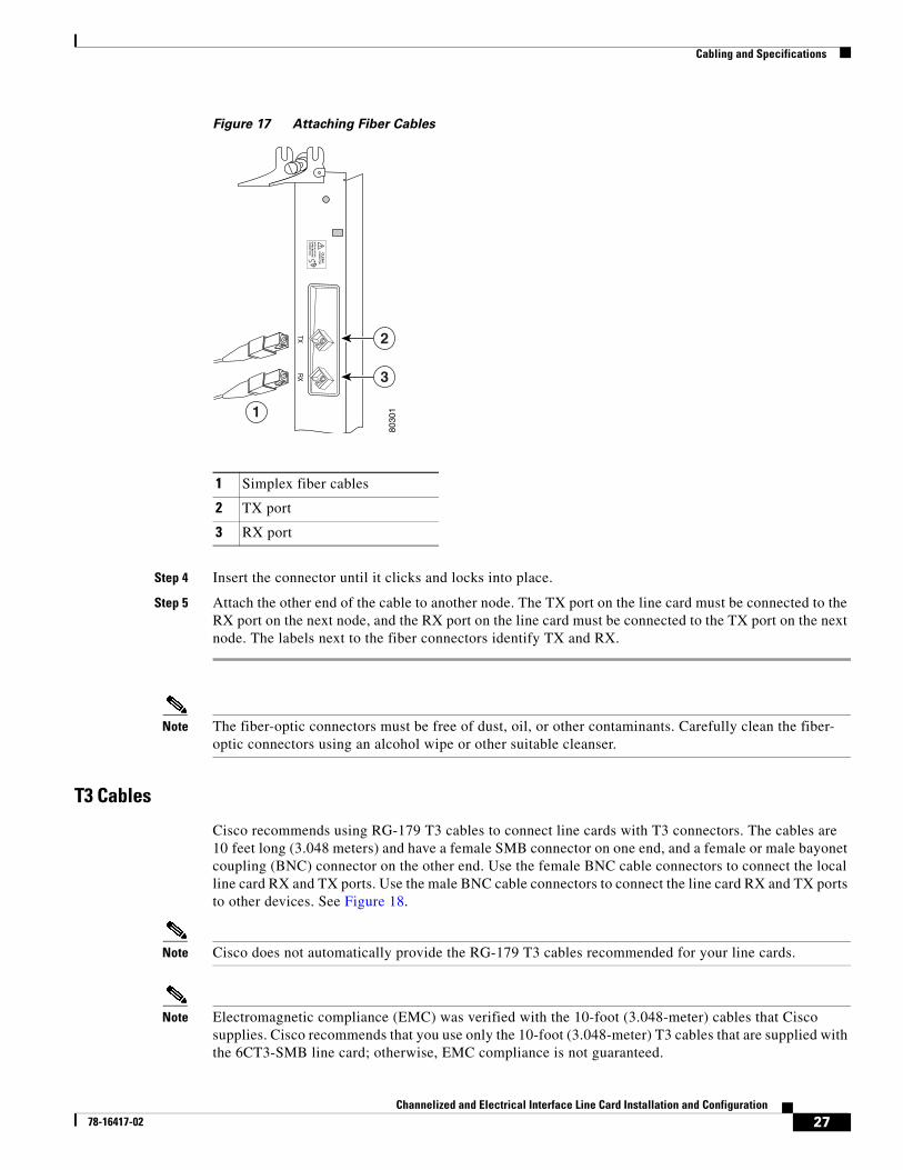
Figure 17 Attaching Fiber Cables
Step 4 Insert the connector until it clicks and locks into place.
Step 5 Attach the other end of the cable to another node. The TX port on the line card must be connected to the RX port on the next node, and the RX port on the line card must be connected to the TX port on the next node. The labels next to the fiber connectors identify TX and RX.
Note The fiber-optic connectors must be free of dust, oil, or other contaminants. Carefully clean the fiber- optic connectors using an alcohol wipe or other suitable cleanser.
T3 Cables
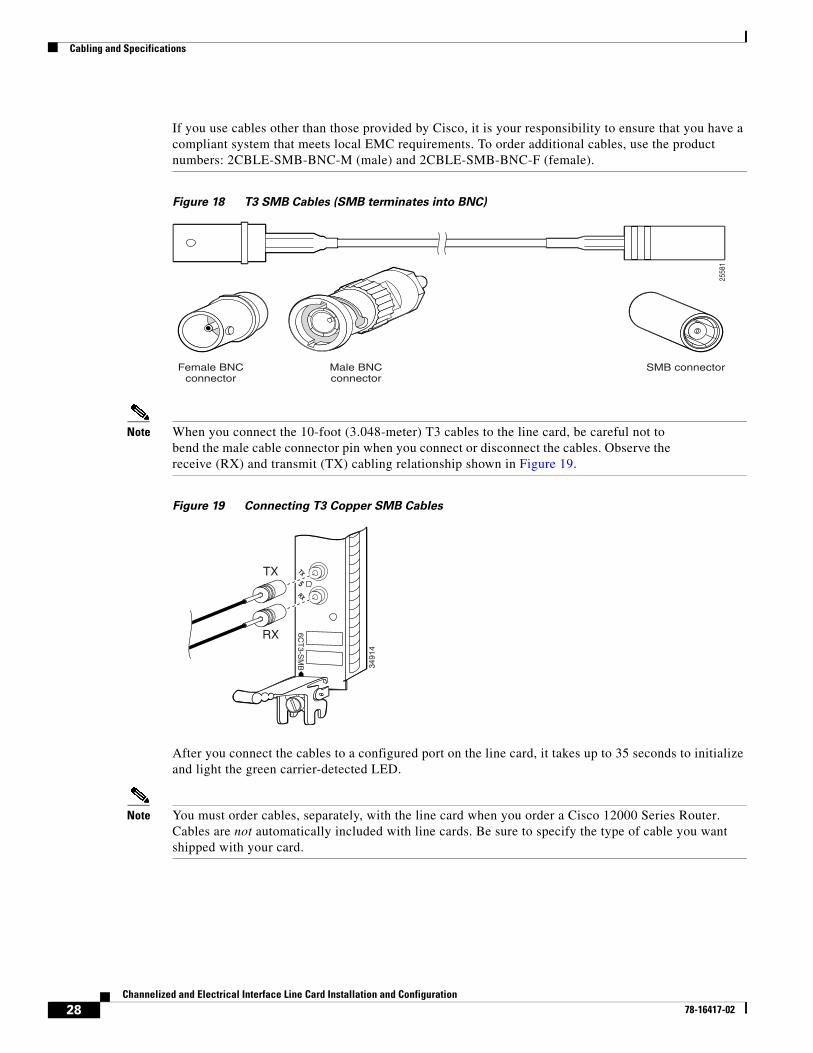
Cisco recommends using RG-179 T3 cables to connect line cards with T3 connectors. The cables are 10 feet long (3.048 meters) and have a female SMB connector on one end, and a female or male bayonet coupling (BNC) connector on the other end. Use the female BNC cable connectors to connect the local line card RX and TX ports. Use the male BNC cable connectors to connect the line card RX and TX ports to other devices. See Figure 18.
Note Cisco does not automatically provide the RG-179 T3 cables recommended for your line cards.
Note Electromagnetic compliance (EMC) was verified with the 10-foot (3.048-meter) cables that Cisco supplies. Cisco recommends that you use only the 10-foot (3.048-meter) T3 cables that are supplied with the 6CT3-SMB line card; otherwise, EMC compliance is not guaranteed.
1 Simplex fiber cables
2 TX port
3 RX port
TXR
X
8030
1
2
3
1
27Channelized and Electrical Interface Line Card Installation and Configuration
78-16417-02
Cabling and Specifications
If you use cables other than those provided by Cisco, it is your responsibility to ensure that you have a compliant system that meets local EMC requirements. To order additional cables, use the product numbers: 2CBLE-SMB-BNC-M (male) and 2CBLE-SMB-BNC-F (female).
Figure 18 T3 SMB Cables (SMB terminates into BNC)
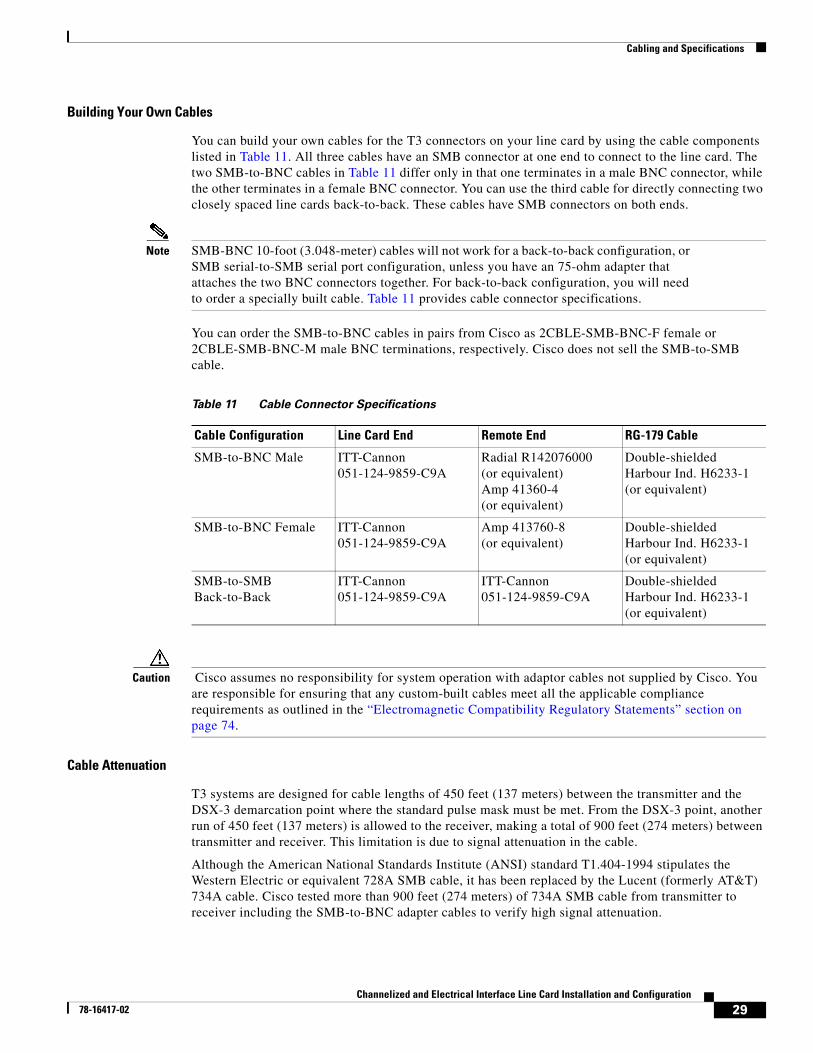
Note When you connect the 10-foot (3.048-meter) T3 cables to the line card, be careful not to bend the male cable connector pin when you connect or disconnect the cables. Observe the receive (RX) and transmit (TX) cabling relationship shown in Figure 19.
Figure 19 Connecting T3 Copper SMB Cables
After you connect the cables to a configured port on the line card, it takes up to 35 seconds to initialize and light the green carrier-detected LED.
Note You must order cables, separately, with the line card when you order a Cisco 12000 Series Router. Cables are not automatically included with line cards. Be sure to specify the type of cable you want shipped with your card.
2558
1
SMB connectorFemale BNCconnector
Male BNCconnector
3491
4
TX
5RX
6CT
3-SM
B
TX
RX
28Channelized and Electrical Interface Line Card Installation and Configuration
78-16417-02
Cabling and Specifications
Building Your Own Cables
You can build your own cables for the T3 connectors on your line card by using the cable components listed in Table 11. All three cables have an SMB connector at one end to connect to the line card. The two SMB-to-BNC cables in Table 11 differ only in that one terminates in a male BNC connector, while the other terminates in a female BNC connector. You can use the third cable for directly connecting two closely spaced line cards back-to-back. These cables have SMB connectors on both ends.
Note SMB-BNC 10-foot (3.048-meter) cables will not work for a back-to-back configuration, or SMB serial-to-SMB serial port configuration, unless you have an 75-ohm adapter that attaches the two BNC connectors together. For back-to-back configuration, you will need to order a specially built cable. Table 11 provides cable connector specifications.
You can order the SMB-to-BNC cables in pairs from Cisco as 2CBLE-SMB-BNC-F female or 2CBLE-SMB-BNC-M male BNC terminations, respectively. Cisco does not sell the SMB-to-SMB cable.
Caution Cisco assumes no responsibility for system operation with adaptor cables not supplied by Cisco. You are responsible for ensuring that any custom-built cables meet all the applicable compliance requirements as outlined in the “Electromagnetic Compatibility Regulatory Statements” section on page 74.
Cable Attenuation
T3 systems are designed for cable lengths of 450 feet (137 meters) between the transmitter and the DSX-3 demarcation point where the standard pulse mask must be met. From the DSX-3 point, another run of 450 feet (137 meters) is allowed to the receiver, making a total of 900 feet (274 meters) between transmitter and receiver. This limitation is due to signal attenuation in the cable.
Although the American National Standards Institute (ANSI) standard T1.404-1994 stipulates the Western Electric or equivalent 728A SMB cable, it has been replaced by the Lucent (formerly AT&T) 734A cable. Cisco tested more than 900 feet (274 meters) of 734A SMB cable from transmitter to receiver including the SMB-to-BNC adapter cables to verify high signal attenuation.
Table 11 Cable Connector Specifications
Cable Configuration Line Card End Remote End RG-179 Cable
SMB-to-BNC Male ITT-Cannon 051-124-9859-C9A
Radial R142076000(or equivalent)Amp 41360-4(or equivalent)
Double-shieldedHarbour Ind. H6233-1(or equivalent)
SMB-to-BNC Female ITT-Cannon 051-124-9859-C9A
Amp 413760-8 (or equivalent)
Double-shieldedHarbour Ind. H6233-1(or equivalent)
SMB-to-SMBBack-to-Back
ITT-Cannon 051-124-9859-C9A
ITT-Cannon 051-124-9859-C9A
Double-shieldedHarbour Ind. H6233-1(or equivalent)
29Channelized and Electrical Interface Line Card Installation and Configuration
78-16417-02
Verifying and Troubleshooting the Line Card Installation
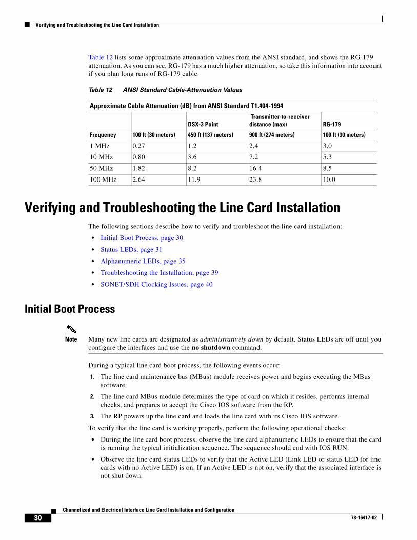
Table 12 lists some approximate attenuation values from the ANSI standard, and shows the RG-179 attenuation. As you can see, RG-179 has a much higher attenuation, so take this information into account if you plan long runs of RG-179 cable.
Verifying and Troubleshooting the Line Card InstallationThe following sections describe how to verify and troubleshoot the line card installation:
• Initial Boot Process, page 30
• Status LEDs, page 31
• Alphanumeric LEDs, page 35
• Troubleshooting the Installation, page 39
• SONET/SDH Clocking Issues, page 40
Initial Boot Process
Note Many new line cards are designated as administratively down by default. Status LEDs are off until you configure the interfaces and use the no shutdown command.
During a typical line card boot process, the following events occur:
1. The line card maintenance bus (MBus) module receives power and begins executing the MBus software.
2. The line card MBus module determines the type of card on which it resides, performs internal checks, and prepares to accept the Cisco IOS software from the RP.
3. The RP powers up the line card and loads the line card with its Cisco IOS software.
To verify that the line card is working properly, perform the following operational checks:
• During the line card boot process, observe the line card alphanumeric LEDs to ensure that the card is running the typical initialization sequence. The sequence should end with IOS RUN.
• Observe the line card status LEDs to verify that the Active LED (Link LED or status LED for line cards with no Active LED) is on. If an Active LED is not on, verify that the associated interface is not shut down.
Table 12 ANSI Standard Cable-Attenuation Values
Approximate Cable Attenuation (dB) from ANSI Standard T1.404-1994
DSX-3 Point Transmitter-to-receiver distance (max) RG-179
Frequency 100 ft (30 meters) 450 ft (137 meters) 900 ft (274 meters) 100 ft (30 meters)
1 MHz 0.27 1.2 2.4 3.0
10 MHz 0.80 3.6 7.2 5.3
50 MHz 1.82 8.2 16.4 8.5
100 MHz 2.64 11.9 23.8 10.0
30Channelized and Electrical Interface Line Card Installation and Configuration
78-16417-02
Verifying and Troubleshooting the Line Card Installation
If one of these conditions is not met, refer to the “Advanced Line Card Troubleshooting” section on page 56 to identify any possible problems.
Status LEDsAfter installing the line card and connecting the interface cables, verify that the line card is working properly by checking the following LEDs on the faceplate:
• Interface status LEDs show the status of each fiber-optic connector. Channelized line cards with optic interfaces can contain some or all of the following status LEDs (see Figure 1, Figure 2, Figure 3, Figure 4, Figure 5, and Figure 6 for your particular model):
– Active—Indicates the active condition of this port
– Carrier—Indicates the status of SONET framing reception on this port
– RX PKT—Indicates that data is being received on this port
Line cards with T3 ports contain a single status LED (see Figure 7, Figure 8, and Figure 9 for your particular model):
• Alphanumeric LEDs. Two four-digit alphanumeric LEDs display messages that explain the state of the line card. (See the “Alphanumeric LEDs” section on page 35.)
The status LEDs might not go on until after you have configured the line card interfaces (or turned them on, if they were shut down). To verify correct operation of each interface, complete the configuration procedures for the line card. (See the “Configuring and Troubleshooting Line Card Interfaces” section on page 40.)
The following sections describe status LED information for each channelized and electrical interface line card:
• 1-Port Channelized OC-12/STM-4 (DS1/E1) ISE Line Card LEDs, page 31
• 1-Port Channelized OC-48/STM-16 ISE Line Card LEDs, page 32
• 4-Port Channelized OC-12/STM-4 ISE Line Card LEDs, page 32
• 1-Port Channelized OC-12/STM-4 (OC-3) Line Card LEDs, page 33
• 1-Port Channelized OC-12/STM-4 (DS3) Line Card LEDs, page 33
• 2-Port Channelized OC-3/STM-1 (DS1/E1) Line Card LEDs, page 33
• 6-Port Channelized T3 (T1) Line Card LED, page 34
• 6-Port and 12-Port DS3 Line Card LED, page 34
• 6-Port and 12-Port E3 Line Card LED, page 35
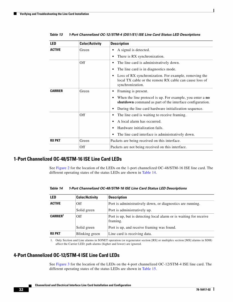
1-Port Channelized OC-12/STM-4 (DS1/E1) ISE Line Card LEDs
See Figure 1 for the location of the LEDs on the 1-port channelized OC-12/STM-4 (DS1/E1) ISE line card. The different operating states of the status LEDs are shown in Table 13.
31Channelized and Electrical Interface Line Card Installation and Configuration
78-16417-02
Verifying and Troubleshooting the Line Card Installation
1-Port Channelized OC-48/STM-16 ISE Line Card LEDs
See Figure 2 for the location of the LEDs on the 1-port channelized OC-48/STM-16 ISE line card. The different operating states of the status LEDs are shown in Table 14.
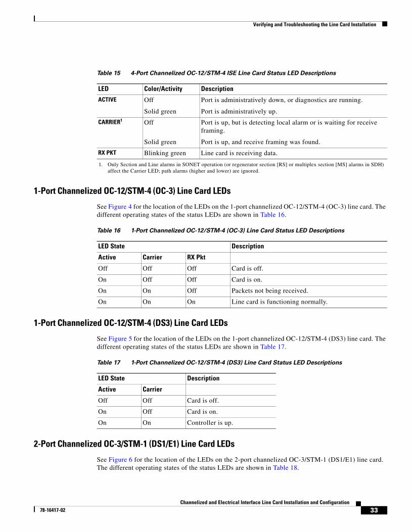
4-Port Channelized OC-12/STM-4 ISE Line Card LEDs
See Figure 3 for the location of the LEDs on the 4-port channelized OC-12/STM-4 ISE line card. The different operating states of the status LEDs are shown in Table 15.
Table 13 1-Port Channelized OC-12/STM-4 (DS1/E1) ISE Line Card Status LED Descriptions
LED Color/Activity Description
ACTIVE Green • A signal is detected.
• There is RX synchronization.
Off • The line card is administratively down.
• The line card is in diagnostics mode.
• Loss of RX synchronization. For example, removing the local TX cable or the remote RX cable can cause loss of synchronization.
CARRIER Green • Framing is present.
• When the line protocol is up. For example, you enter a no shutdown command as part of the interface configuration.
• During the line card hardware initialization sequence.
Off • The line card is waiting to receive framing.
• A local alarm has occurred.
• Hardware initialization fails.
• The line card interface is administratively down.
RX PKT Green Packets are being received on this interface.
Off Packets are not being received on this interface.
Table 14 1-Port Channelized OC-48/STM-16 ISE Line Card Status LED Descriptions
LED Color/Activity Description
ACTIVE Off
Solid green
Port is administratively down, or diagnostics are running.
Port is administratively up.
CARRIER1 Off
Solid green
Port is up, but is detecting local alarm or is waiting for receive framing.
Port is up, and receive framing was found.
RX PKT Blinking green Line card is receiving data.
1. Only Section and Line alarms in SONET operation (or regenerator section [RS] or multiplex section [MS] alarms in SDH) affect the Carrier LED; path alarms (higher and lower) are ignored.
32Channelized and Electrical Interface Line Card Installation and Configuration
78-16417-02
Verifying and Troubleshooting the Line Card Installation
1-Port Channelized OC-12/STM-4 (OC-3) Line Card LEDs
See Figure 4 for the location of the LEDs on the 1-port channelized OC-12/STM-4 (OC-3) line card. The different operating states of the status LEDs are shown in Table 16.
1-Port Channelized OC-12/STM-4 (DS3) Line Card LEDs
See Figure 5 for the location of the LEDs on the 1-port channelized OC-12/STM-4 (DS3) line card. The different operating states of the status LEDs are shown in Table 17.
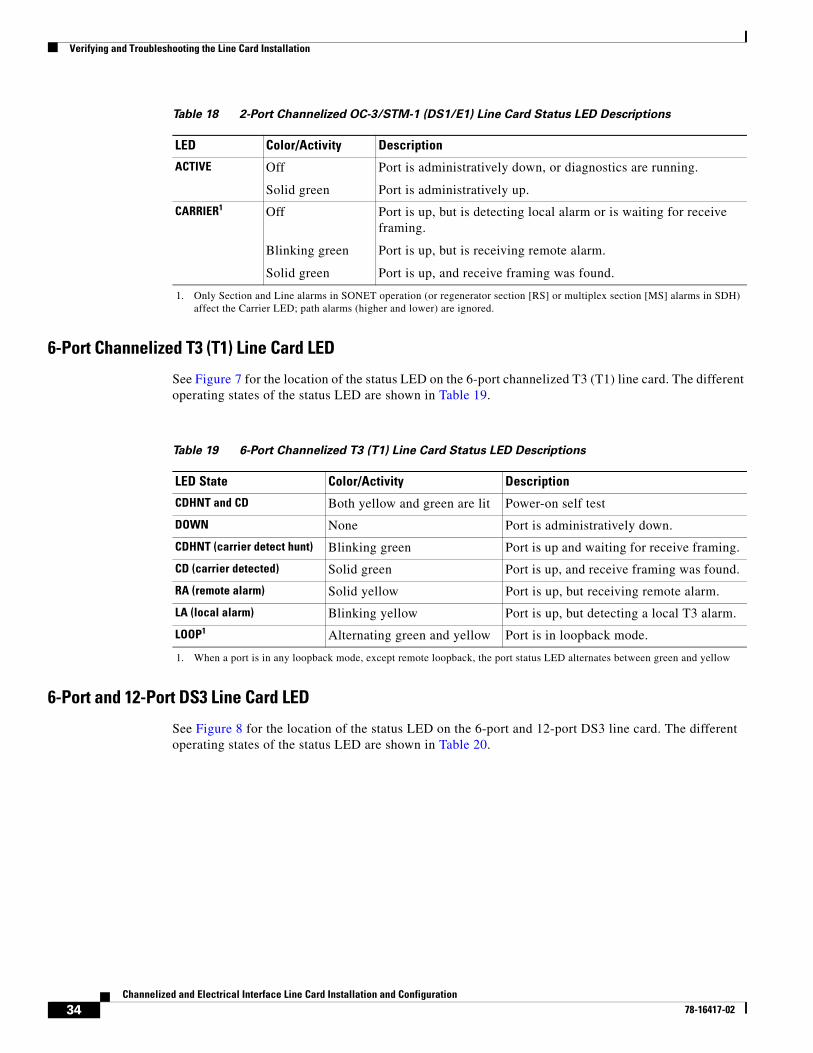
2-Port Channelized OC-3/STM-1 (DS1/E1) Line Card LEDs
See Figure 6 for the location of the LEDs on the 2-port channelized OC-3/STM-1 (DS1/E1) line card. The different operating states of the status LEDs are shown in Table 18.
Table 15 4-Port Channelized OC-12/STM-4 ISE Line Card Status LED Descriptions
LED Color/Activity Description
ACTIVE Off
Solid green
Port is administratively down, or diagnostics are running.
Port is administratively up.
CARRIER1 Off
Solid green
Port is up, but is detecting local alarm or is waiting for receive framing.
Port is up, and receive framing was found.
RX PKT Blinking green Line card is receiving data.
1. Only Section and Line alarms in SONET operation (or regenerator section [RS] or multiplex section [MS] alarms in SDH) affect the Carrier LED; path alarms (higher and lower) are ignored.
Table 16 1-Port Channelized OC-12/STM-4 (OC-3) Line Card Status LED Descriptions
LED State Description
Active Carrier RX Pkt
Off Off Off Card is off.
On Off Off Card is on.
On On Off Packets not being received.
On On On Line card is functioning normally.
Table 17 1-Port Channelized OC-12/STM-4 (DS3) Line Card Status LED Descriptions
LED State Description
Active Carrier
Off Off Card is off.
On Off Card is on.
On On Controller is up.
33Channelized and Electrical Interface Line Card Installation and Configuration
78-16417-02
Verifying and Troubleshooting the Line Card Installation
6-Port Channelized T3 (T1) Line Card LED
See Figure 7 for the location of the status LED on the 6-port channelized T3 (T1) line card. The different operating states of the status LED are shown in Table 19.
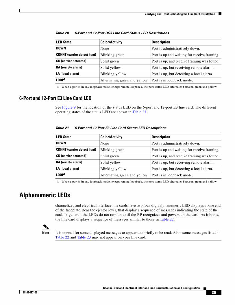
6-Port and 12-Port DS3 Line Card LED
See Figure 8 for the location of the status LED on the 6-port and 12-port DS3 line card. The different operating states of the status LED are shown in Table 20.
Table 18 2-Port Channelized OC-3/STM-1 (DS1/E1) Line Card Status LED Descriptions
LED Color/Activity Description
ACTIVE Off
Solid green
Port is administratively down, or diagnostics are running.
Port is administratively up.
CARRIER1 Off
Blinking green
Solid green
Port is up, but is detecting local alarm or is waiting for receive framing.
Port is up, but is receiving remote alarm.
Port is up, and receive framing was found.
1. Only Section and Line alarms in SONET operation (or regenerator section [RS] or multiplex section [MS] alarms in SDH) affect the Carrier LED; path alarms (higher and lower) are ignored.
Table 19 6-Port Channelized T3 (T1) Line Card Status LED Descriptions
LED State Color/Activity Description
CDHNT and CD Both yellow and green are lit Power-on self test
DOWN None Port is administratively down.
CDHNT (carrier detect hunt) Blinking green Port is up and waiting for receive framing.
CD (carrier detected) Solid green Port is up, and receive framing was found.
RA (remote alarm) Solid yellow Port is up, but receiving remote alarm.
LA (local alarm) Blinking yellow Port is up, but detecting a local T3 alarm.
LOOP1 Alternating green and yellow Port is in loopback mode.
1. When a port is in any loopback mode, except remote loopback, the port status LED alternates between green and yellow
34Channelized and Electrical Interface Line Card Installation and Configuration
78-16417-02
Verifying and Troubleshooting the Line Card Installation
6-Port and 12-Port E3 Line Card LED
See Figure 9 for the location of the status LED on the 6-port and 12-port E3 line card. The different operating states of the status LED are shown in Table 21.
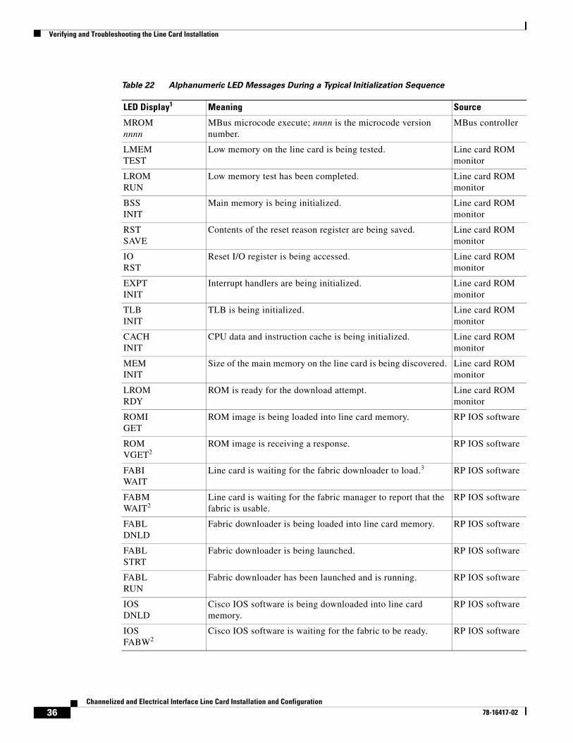
Alphanumeric LEDschannelized and electrical interface line cards have two four-digit alphanumeric LED displays at one end of the faceplate, near the ejector lever, that display a sequence of messages indicating the state of the card. In general, the LEDs do not turn on until the RP recognizes and powers up the card. As it boots, the line card displays a sequence of messages similar to those in Table 22.
Note It is normal for some displayed messages to appear too briefly to be read. Also, some messages listed in Table 22 and Table 23 may not appear on your line card.
Table 20 6-Port and 12-Port DS3 Line Card Status LED Descriptions
LED State Color/Activity Description
DOWN None Port is administratively down.
CDHNT (carrier detect hunt) Blinking green Port is up and waiting for receive framing.
CD (carrier detected) Solid green Port is up, and receive framing was found.
RA (remote alarm) Solid yellow Port is up, but receiving remote alarm.
LA (local alarm) Blinking yellow Port is up, but detecting a local alarm.
LOOP1 Alternating green and yellow Port is in loopback mode.
1. When a port is in any loopback mode, except remote loopback, the port status LED alternates between green and yellow
Table 21 6-Port and 12-Port E3 Line Card Status LED Descriptions
LED State Color/Activity Description
DOWN None Port is administratively down.
CDHNT (carrier detect hunt) Blinking green Port is up and waiting for receive framing.
CD (carrier detected) Solid green Port is up, and receive framing was found.
RA (remote alarm) Solid yellow Port is up, but receiving remote alarm.
LA (local alarm) Blinking yellow Port is up, but detecting a local alarm.
LOOP1 Alternating green and yellow Port is in loopback mode.
1. When a port is in any loopback mode, except remote loopback, the port status LED alternates between green and yellow
35Channelized and Electrical Interface Line Card Installation and Configuration
78-16417-02
Verifying and Troubleshooting the Line Card Installation
Table 22 Alphanumeric LED Messages During a Typical Initialization Sequence
LED Display1 Meaning Source
MROMnnnn
MBus microcode execute; nnnn is the microcode version number.
MBus controller
LMEMTEST
Low memory on the line card is being tested. Line card ROM monitor
LROMRUN
Low memory test has been completed. Line card ROM monitor
BSSINIT
Main memory is being initialized. Line card ROM monitor
RSTSAVE
Contents of the reset reason register are being saved. Line card ROM monitor
IORST
Reset I/O register is being accessed. Line card ROM monitor
EXPTINIT
Interrupt handlers are being initialized. Line card ROM monitor
TLBINIT
TLB is being initialized. Line card ROM monitor
CACHINIT
CPU data and instruction cache is being initialized. Line card ROM monitor
MEMINIT
Size of the main memory on the line card is being discovered. Line card ROM monitor
LROMRDY
ROM is ready for the download attempt. Line card ROM monitor
ROMIGET
ROM image is being loaded into line card memory. RP IOS software
ROMVGET2
ROM image is receiving a response. RP IOS software
FABIWAIT
Line card is waiting for the fabric downloader to load.3 RP IOS software
FABMWAIT2
Line card is waiting for the fabric manager to report that the fabric is usable.
RP IOS software
FABLDNLD
Fabric downloader is being loaded into line card memory. RP IOS software
FABLSTRT
Fabric downloader is being launched. RP IOS software
FABLRUN
Fabric downloader has been launched and is running. RP IOS software
IOSDNLD
Cisco IOS software is being downloaded into line card memory.
RP IOS software
IOSFABW2
Cisco IOS software is waiting for the fabric to be ready. RP IOS software
36Channelized and Electrical Interface Line Card Installation and Configuration
78-16417-02
Verifying and Troubleshooting the Line Card Installation
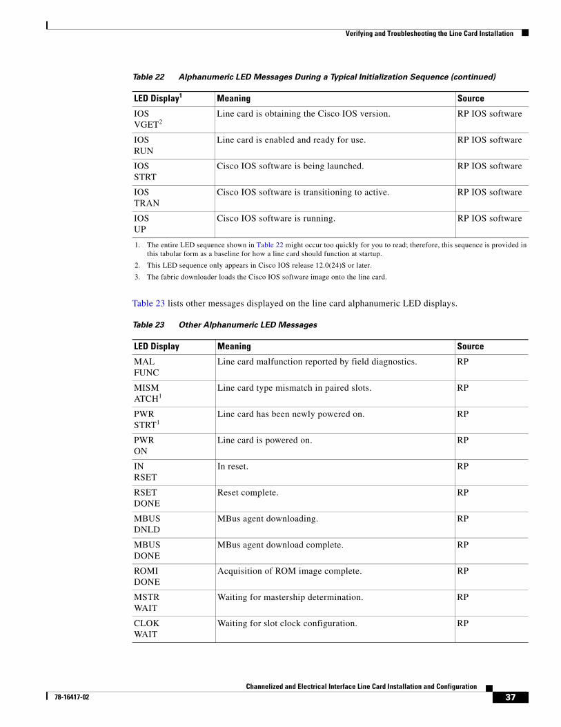
Table 23 lists other messages displayed on the line card alphanumeric LED displays.
IOSVGET2
Line card is obtaining the Cisco IOS version. RP IOS software
IOSRUN
Line card is enabled and ready for use. RP IOS software
IOSSTRT
Cisco IOS software is being launched. RP IOS software
IOS TRAN
Cisco IOS software is transitioning to active. RP IOS software
IOSUP
Cisco IOS software is running. RP IOS software
1. The entire LED sequence shown in Table 22 might occur too quickly for you to read; therefore, this sequence is provided in this tabular form as a baseline for how a line card should function at startup.
2. This LED sequence only appears in Cisco IOS release 12.0(24)S or later.
3. The fabric downloader loads the Cisco IOS software image onto the line card.
Table 22 Alphanumeric LED Messages During a Typical Initialization Sequence (continued)
LED Display1 Meaning Source
Table 23 Other Alphanumeric LED Messages
LED Display Meaning Source
MALFUNC
Line card malfunction reported by field diagnostics. RP
MISMATCH1
Line card type mismatch in paired slots. RP
PWRSTRT1
Line card has been newly powered on. RP
PWRON
Line card is powered on. RP
INRSET
In reset. RP
RSETDONE
Reset complete. RP
MBUSDNLD
MBus agent downloading. RP
MBUSDONE
MBus agent download complete. RP
ROMIDONE
Acquisition of ROM image complete. RP
MSTRWAIT
Waiting for mastership determination. RP
CLOKWAIT
Waiting for slot clock configuration. RP
37Channelized and Electrical Interface Line Card Installation and Configuration
78-16417-02
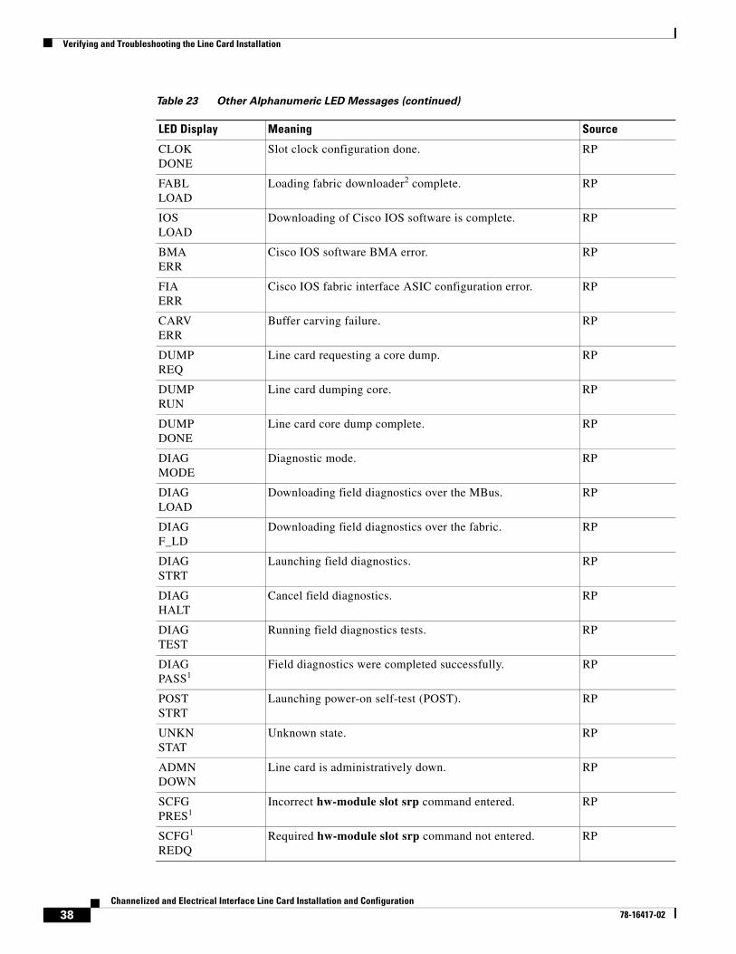
Verifying and Troubleshooting the Line Card Installation
CLOKDONE
Slot clock configuration done. RP
FABLLOAD
Loading fabric downloader2 complete. RP
IOSLOAD
Downloading of Cisco IOS software is complete. RP
BMAERR
Cisco IOS software BMA error. RP
FIAERR
Cisco IOS fabric interface ASIC configuration error. RP
CARVERR
Buffer carving failure. RP
DUMPREQ
Line card requesting a core dump. RP
DUMPRUN
Line card dumping core. RP
DUMPDONE
Line card core dump complete. RP
DIAGMODE
Diagnostic mode. RP
DIAGLOAD
Downloading field diagnostics over the MBus. RP
DIAGF_LD
Downloading field diagnostics over the fabric. RP
DIAGSTRT
Launching field diagnostics. RP
DIAGHALT
Cancel field diagnostics. RP
DIAGTEST
Running field diagnostics tests. RP
DIAGPASS1
Field diagnostics were completed successfully. RP
POSTSTRT
Launching power-on self-test (POST). RP
UNKNSTAT
Unknown state. RP
ADMNDOWN
Line card is administratively down. RP
SCFGPRES1
Incorrect hw-module slot srp command entered. RP
SCFG1
REDQRequired hw-module slot srp command not entered. RP
Table 23 Other Alphanumeric LED Messages (continued)
LED Display Meaning Source
38Channelized and Electrical Interface Line Card Installation and Configuration
78-16417-02
Verifying and Troubleshooting the Line Card Installation
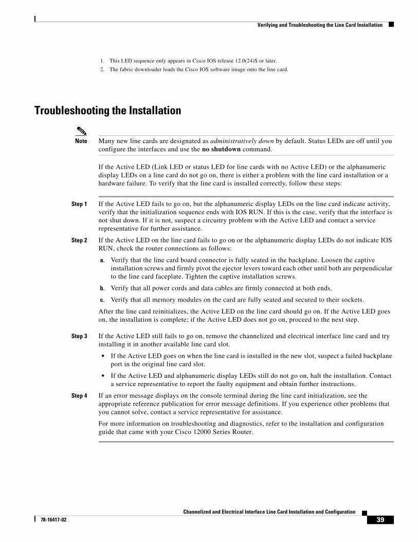
Troubleshooting the Installation
Note Many new line cards are designated as administratively down by default. Status LEDs are off until you configure the interfaces and use the no shutdown command.
If the Active LED (Link LED or status LED for line cards with no Active LED) or the alphanumeric display LEDs on a line card do not go on, there is either a problem with the line card installation or a hardware failure. To verify that the line card is installed correctly, follow these steps:
Step 1 If the Active LED fails to go on, but the alphanumeric display LEDs on the line card indicate activity, verify that the initialization sequence ends with IOS RUN. If this is the case, verify that the interface is not shut down. If it is not, suspect a circuitry problem with the Active LED and contact a service representative for further assistance.
Step 2 If the Active LED on the line card fails to go on or the alphanumeric display LEDs do not indicate IOS RUN, check the router connections as follows:
a. Verify that the line card board connector is fully seated in the backplane. Loosen the captive installation screws and firmly pivot the ejector levers toward each other until both are perpendicular to the line card faceplate. Tighten the captive installation screws.
b. Verify that all power cords and data cables are firmly connected at both ends.
c. Verify that all memory modules on the card are fully seated and secured to their sockets.
After the line card reinitializes, the Active LED on the line card should go on. If the Active LED goes on, the installation is complete; if the Active LED does not go on, proceed to the next step.
Step 3 If the Active LED still fails to go on, remove the channelized and electrical interface line card and try
installing it in another available line card slot.
• If the Active LED goes on when the line card is installed in the new slot, suspect a failed backplane port in the original line card slot.
• If the Active LED and alphanumeric display LEDs still do not go on, halt the installation. Contact a service representative to report the faulty equipment and obtain further instructions.
Step 4 If an error message displays on the console terminal during the line card initialization, see the appropriate reference publication for error message definitions. If you experience other problems that you cannot solve, contact a service representative for assistance.
For more information on troubleshooting and diagnostics, refer to the installation and configuration guide that came with your Cisco 12000 Series Router.
1. This LED sequence only appears in Cisco IOS release 12.0(24)S or later.
2. The fabric downloader loads the Cisco IOS software image onto the line card.
39Channelized and Electrical Interface Line Card Installation and Configuration
78-16417-02
Configuring and Troubleshooting Line Card Interfaces
SONET/SDH Clocking IssuesThis section provides an overview of SONET/SDH clocking issues and is applicable to the 1-port channelized OC-48/STM-16 ISE and 4-port channelized OC-12/STM-4 ISE line cards. These line cards support both line and internal clocking functions. Line clocking is derived from the incoming signal from a given port. Internal clocking is derived from the clock that is internal to the line card.
Each port can be configured independently of the other in a line-timed setup, going back as far as the first payload processor. However, on the 1-port channelized OC-48/STM-16 ISE and 4-port channelized OC-12/STM-4 ISE line cards, the second level of payload processing ties the ports to a common clock source that is timed from only one port. This can result in pointer justifications if the remaining ports are not synchronous. However, with a properly configured router, these pointer justifications can be limited to provide the same performance as a SONET cross-connect device.
Note Pointer justifications do not affect data throughput. All configurations of the1-port channelized OC-48/STM-16 ISE and 4-port channelized OC-12/STM-4 ISE line cards provide total data throughput regardless of pointer justifications. Under no circumstances does any data loss occur. All configurations provide 100 percent error-free data flow.
These line cards use Stratum3 (S3) as the internal clock reference. However, if one of the ports is Stratum1 (S1) accurate, it can be used as the local reference for the system clock. In this case, pointer justifications are very limited. If the system clock is timed from an S1 clock source, from a valid SONET network, then there will be no pointer justifications on any synchronous interface. There are minimal pointer justifications (limited to S1 pointer justifications) on any asynchronous interface if it is on another SONET network. Pointer justification in this case is proportional to the accuracy of the other port clock.
Note When using the show controller pos command, Positive Stuff Event (PSE) and Negative Stuff Event (NSE) values can be safely ignored.
The 1-port channelized OC-48/STM-16 ISE and 4-port channelized OC-12/STM-4 ISE line cards can select an input port as the source of synchronization for the system clock. This eliminates pointer justifications on any port that is synchronous with the selected port. Any other port on that line card that is not synchronous to the selected reference port will encounter pointer justifications at a rate proportional to clock accuracy of the port.
If the port is locally timed, it is Stratum3. If the port is line-timed, it depends on the attached network. It could be another Stratum3 clock, a Stratum1, or something much worse. This issue only applies to multi-port cards and can be avoided if all ports on the line card are connected to the same SONET/SDH network.
Configuring and Troubleshooting Line Card InterfacesThis section provides procedures for configuring and troubleshooting the channelized and electrical interface line card:
• Configuring the 1-Port Channelized OC-12/STM-4 (DS1/E1) ISE Line Card, page 41
• Configuring the 1-Port Channelized OC-48/STM-16 ISE and 4-Port Channelized OC-12/STM-4 ISE Line Cards, page 42
• Configuring the 1-Port Channelized OC-12/STM-4 (OC-3) Line Card, page 44
40Channelized and Electrical Interface Line Card Installation and Configuration
78-16417-02
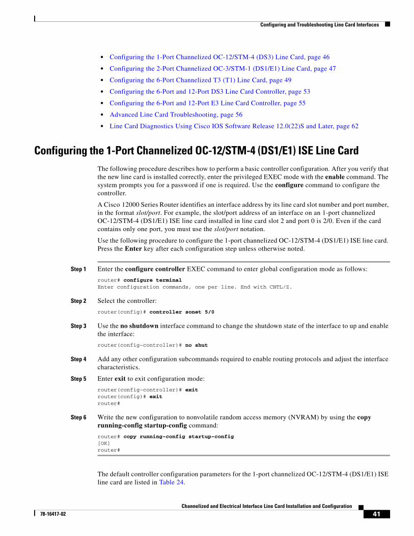
Configuring and Troubleshooting Line Card Interfaces
• Configuring the 1-Port Channelized OC-12/STM-4 (DS3) Line Card, page 46
• Configuring the 2-Port Channelized OC-3/STM-1 (DS1/E1) Line Card, page 47
• Configuring the 6-Port Channelized T3 (T1) Line Card, page 49
• Configuring the 6-Port and 12-Port DS3 Line Card Controller, page 53
• Configuring the 6-Port and 12-Port E3 Line Card Controller, page 55
• Advanced Line Card Troubleshooting, page 56
• Line Card Diagnostics Using Cisco IOS Software Release 12.0(22)S and Later, page 62
Configuring the 1-Port Channelized OC-12/STM-4 (DS1/E1) ISE Line CardThe following procedure describes how to perform a basic controller configuration. After you verify that the new line card is installed correctly, enter the privileged EXEC mode with the enable command. The system prompts you for a password if one is required. Use the configure command to configure the controller.
A Cisco 12000 Series Router identifies an interface address by its line card slot number and port number, in the format slot/port. For example, the slot/port address of an interface on an 1-port channelized OC-12/STM-4 (DS1/E1) ISE line card installed in line card slot 2 and port 0 is 2/0. Even if the card contains only one port, you must use the slot/port notation.
Use the following procedure to configure the 1-port channelized OC-12/STM-4 (DS1/E1) ISE line card. Press the Enter key after each configuration step unless otherwise noted.
Step 1 Enter the configure controller EXEC command to enter global configuration mode as follows:
router# configure terminalEnter configuration commands, one per line. End with CNTL/Z.
Step 2 Select the controller:
router(config)# controller sonet 5/0
Step 3 Use the no shutdown interface command to change the shutdown state of the interface to up and enable the interface:
router(config-controller)# no shut
Step 4 Add any other configuration subcommands required to enable routing protocols and adjust the interface characteristics.
Step 5 Enter exit to exit configuration mode:
router(config-controller)# exitrouter(config)# exitrouter#
Step 6 Write the new configuration to nonvolatile random access memory (NVRAM) by using the copy running-config startup-config command:
router# copy running-config startup-config[OK]router#
The default controller configuration parameters for the 1-port channelized OC-12/STM-4 (DS1/E1) ISE line card are listed in Table 24.
41Channelized and Electrical Interface Line Card Installation and Configuration
78-16417-02
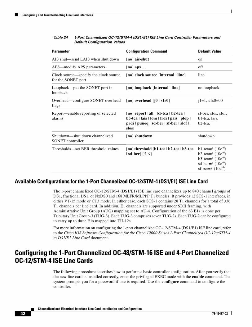
Configuring and Troubleshooting Line Card Interfaces
Available Configurations for the 1-Port Channelized OC-12/STM-4 (DS1/E1) ISE Line Card
The 1-port channelized OC-12/STM-4 (DS1/E1) ISE line card channelizes up to 840 channel groups of DS1, fractional DS1, or NxDS0 and 168 MLFR/MLPPP T1 bundles. It provides 12 STS-1 interfaces, in either VT-15 mode or CT3 mode. In either case, each STS-1 contains 28 T1 channels for a total of 336 T1 channels per line card. In addition, E1 channels are supported under SDH framing, with Administrative Unit Group (AUG) mapping set to AU-4. Configuration of the 63 E1s is done per Tributary Unit Group-3 (TUG-3). Each TUG-3 comprises seven TUG-2s. Each TUG-2 can be configured to carry up to three E1s mapped into TU-12s.
For more information on configuring the 1-port channelized OC-12/STM-4 (DS1/E1) ISE line card, refer to the Cisco IOS Software Configuration for the Cisco 12000 Series 1-Port Channelized OC-12c/STM-4 to DS1/E1 Line Card document.
Configuring the 1-Port Channelized OC-48/STM-16 ISE and 4-Port Channelized OC-12/STM-4 ISE Line Cards
The following procedure describes how to perform a basic controller configuration. After you verify that the new line card is installed correctly, enter the privileged EXEC mode with the enable command. The system prompts you for a password if one is required. Use the configure command to configure the controller.
Table 24 1-Port Channelized OC-12/STM-4 (DS1/E1) ISE Line Card Controller Parameters and
Default Configuration Values
Parameter Configuration Command Default Value
AIS shut—send LAIS when shut down [no] ais-shut on
APS—modify APS parameters [no] aps ... off
Clock source—specify the clock source for the SONET port
[no] clock source [internal | line] line
Loopback—put the SONET port in loopback
[no] loopback [internal | line] no loopback
Overhead—configure SONET overhead flags
[no] overhead [j0 | s1s0] j1=1; s1s0=00
Report—enable reporting of selected alarms
[no] report [all | b1-tca | b2-tca | b3-tca | lais | lom | lrdi | pais | plop | prdi | puneq | sd-ber | sf-ber | slof | slos]
sf-ber, slos, slof, b1-tca, lais, b2-tca,
Shutdown—shut down channelized SONET controller
[no] shutdown shutdown
Thresholds—set BER threshold values [no] threshold [b1-tca | b2-tca | b3-tca | sd-ber] [3..9]
b1-tca=6 (10e-6)b2-tca=6 (10e-6)b3-tca=6 (10e-6)sd-ber=6 (10e-6)sf-ber=3 (10e-3)
42Channelized and Electrical Interface Line Card Installation and Configuration
78-16417-02
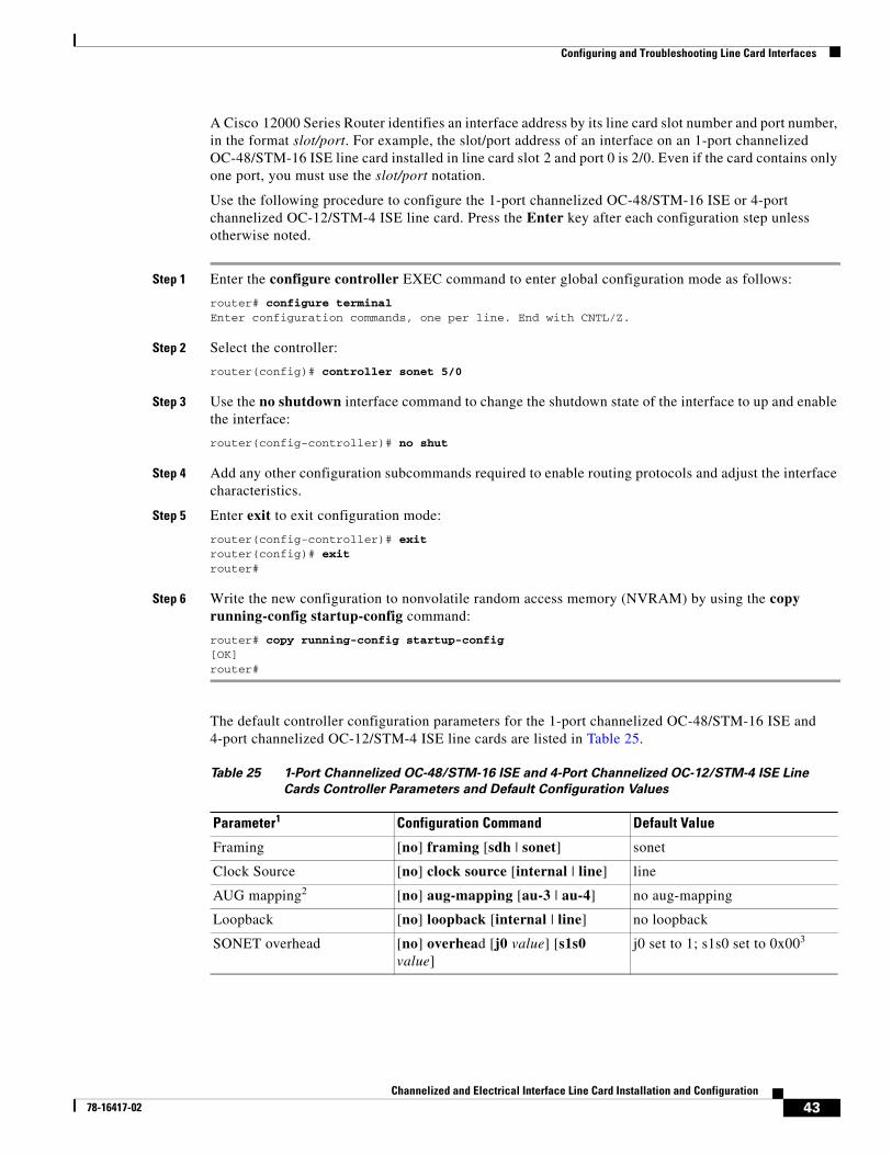
Configuring and Troubleshooting Line Card Interfaces
A Cisco 12000 Series Router identifies an interface address by its line card slot number and port number, in the format slot/port. For example, the slot/port address of an interface on an 1-port channelized OC-48/STM-16 ISE line card installed in line card slot 2 and port 0 is 2/0. Even if the card contains only one port, you must use the slot/port notation.
Use the following procedure to configure the 1-port channelized OC-48/STM-16 ISE or 4-port channelized OC-12/STM-4 ISE line card. Press the Enter key after each configuration step unless otherwise noted.
Step 1 Enter the configure controller EXEC command to enter global configuration mode as follows:
router# configure terminalEnter configuration commands, one per line. End with CNTL/Z.
Step 2 Select the controller:
router(config)# controller sonet 5/0
Step 3 Use the no shutdown interface command to change the shutdown state of the interface to up and enable the interface:
router(config-controller)# no shut
Step 4 Add any other configuration subcommands required to enable routing protocols and adjust the interface characteristics.
Step 5 Enter exit to exit configuration mode:
router(config-controller)# exitrouter(config)# exitrouter#
Step 6 Write the new configuration to nonvolatile random access memory (NVRAM) by using the copy running-config startup-config command:
router# copy running-config startup-config[OK]router#
The default controller configuration parameters for the 1-port channelized OC-48/STM-16 ISE and 4-port channelized OC-12/STM-4 ISE line cards are listed in Table 25.
Table 25 1-Port Channelized OC-48/STM-16 ISE and 4-Port Channelized OC-12/STM-4 ISE Line
Cards Controller Parameters and Default Configuration Values
Parameter1 Configuration Command Default Value
Framing [no] framing [sdh | sonet] sonet
Clock Source [no] clock source [internal | line] line
AUG mapping2 [no] aug-mapping [au-3 | au-4] no aug-mapping
Loopback [no] loopback [internal | line] no loopback
SONET overhead [no] overhead [j0 value] [s1s0 value]
j0 set to 1; s1s0 set to 0x003
43Channelized and Electrical Interface Line Card Installation and Configuration
78-16417-02
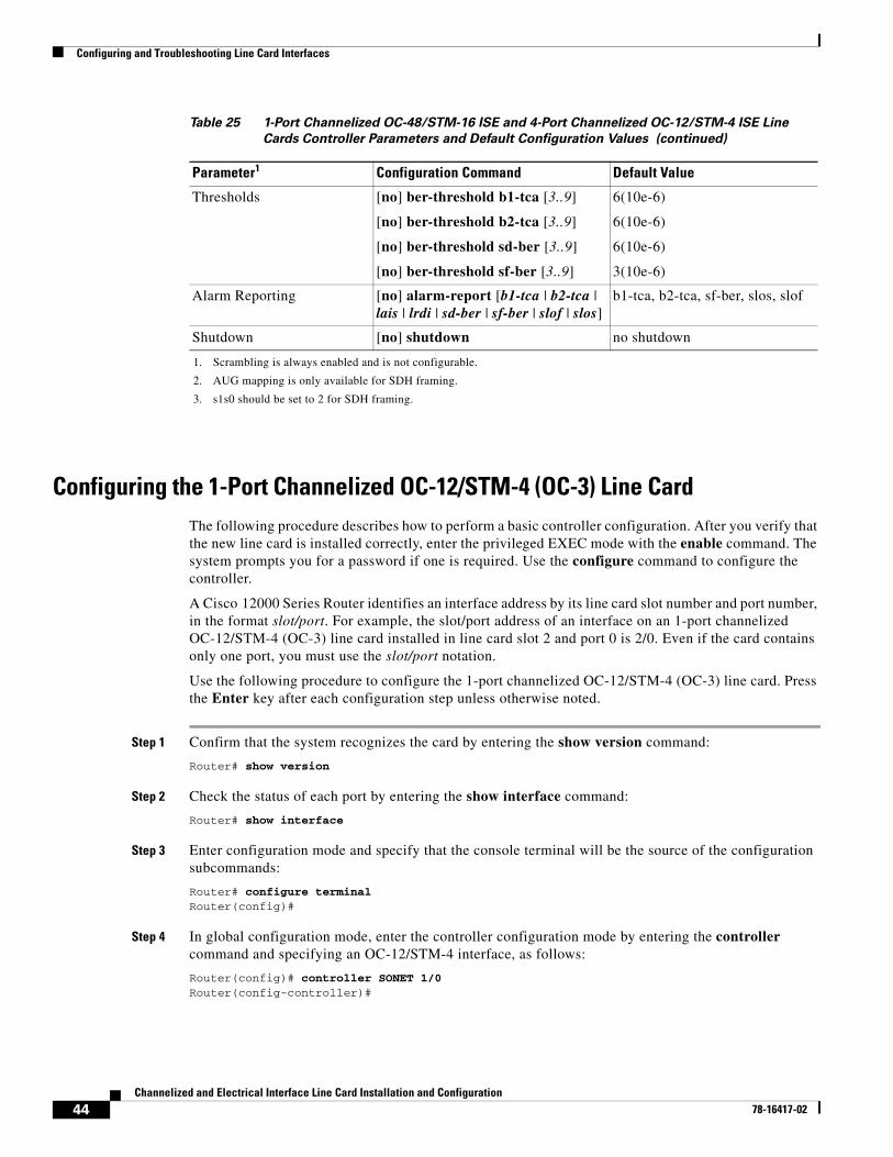
Configuring and Troubleshooting Line Card Interfaces
Configuring the 1-Port Channelized OC-12/STM-4 (OC-3) Line CardThe following procedure describes how to perform a basic controller configuration. After you verify that the new line card is installed correctly, enter the privileged EXEC mode with the enable command. The system prompts you for a password if one is required. Use the configure command to configure the controller.
A Cisco 12000 Series Router identifies an interface address by its line card slot number and port number, in the format slot/port. For example, the slot/port address of an interface on an 1-port channelized OC-12/STM-4 (OC-3) line card installed in line card slot 2 and port 0 is 2/0. Even if the card contains only one port, you must use the slot/port notation.
Use the following procedure to configure the 1-port channelized OC-12/STM-4 (OC-3) line card. Press the Enter key after each configuration step unless otherwise noted.
Step 1 Confirm that the system recognizes the card by entering the show version command:
Router# show version
Step 2 Check the status of each port by entering the show interface command:
Router# show interface
Step 3 Enter configuration mode and specify that the console terminal will be the source of the configuration subcommands:
Router# configure terminal Router(config)#
Step 4 In global configuration mode, enter the controller configuration mode by entering the controller command and specifying an OC-12/STM-4 interface, as follows:
Router(config)# controller SONET 1/0Router(config-controller)#
Thresholds [no] ber-threshold b1-tca [3..9]
[no] ber-threshold b2-tca [3..9]
[no] ber-threshold sd-ber [3..9]
[no] ber-threshold sf-ber [3..9]
6(10e-6)
6(10e-6)
6(10e-6)
3(10e-6)
Alarm Reporting [no] alarm-report [b1-tca | b2-tca | lais | lrdi | sd-ber | sf-ber | slof | slos]
b1-tca, b2-tca, sf-ber, slos, slof
Shutdown [no] shutdown no shutdown
1. Scrambling is always enabled and is not configurable.
2. AUG mapping is only available for SDH framing.
3. s1s0 should be set to 2 for SDH framing.
Table 25 1-Port Channelized OC-48/STM-16 ISE and 4-Port Channelized OC-12/STM-4 ISE Line
Cards Controller Parameters and Default Configuration Values (continued)
Parameter1 Configuration Command Default Value
44Channelized and Electrical Interface Line Card Installation and Configuration
78-16417-02
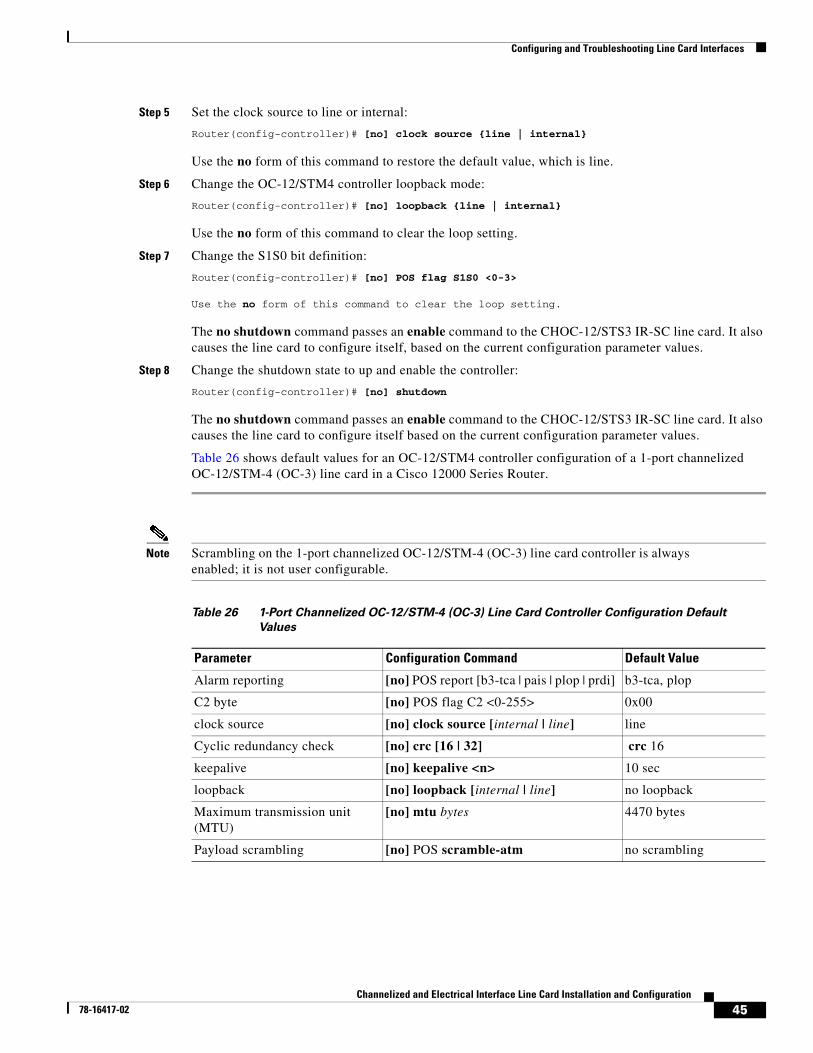
Configuring and Troubleshooting Line Card Interfaces
Step 5 Set the clock source to line or internal:
Router(config-controller)# [no] clock source {line | internal}
Use the no form of this command to restore the default value, which is line.
Step 6 Change the OC-12/STM4 controller loopback mode:
Router(config-controller)# [no] loopback {line | internal}
Use the no form of this command to clear the loop setting.
Step 7 Change the S1S0 bit definition:
Router(config-controller)# [no] POS flag S1S0 <0-3>
Use the no form of this command to clear the loop setting.
The no shutdown command passes an enable command to the CHOC-12/STS3 IR-SC line card. It also causes the line card to configure itself, based on the current configuration parameter values.
Step 8 Change the shutdown state to up and enable the controller:
Router(config-controller)# [no] shutdown
The no shutdown command passes an enable command to the CHOC-12/STS3 IR-SC line card. It also causes the line card to configure itself based on the current configuration parameter values.
Table 26 shows default values for an OC-12/STM4 controller configuration of a 1-port channelized OC-12/STM-4 (OC-3) line card in a Cisco 12000 Series Router.
Note Scrambling on the 1-port channelized OC-12/STM-4 (OC-3) line card controller is always enabled; it is not user configurable.
Table 26 1-Port Channelized OC-12/STM-4 (OC-3) Line Card Controller Configuration Default
Values
Parameter Configuration Command Default Value
Alarm reporting [no] POS report [b3-tca | pais | plop | prdi] b3-tca, plop
C2 byte [no] POS flag C2 <0-255> 0x00
clock source [no] clock source [internal | line] line
Cyclic redundancy check [no] crc [16 | 32] crc 16
keepalive [no] keepalive <n> 10 sec
loopback [no] loopback [internal | line] no loopback
Maximum transmission unit (MTU)
[no] mtu bytes 4470 bytes
Payload scrambling [no] POS scramble-atm no scrambling
45Channelized and Electrical Interface Line Card Installation and Configuration
78-16417-02
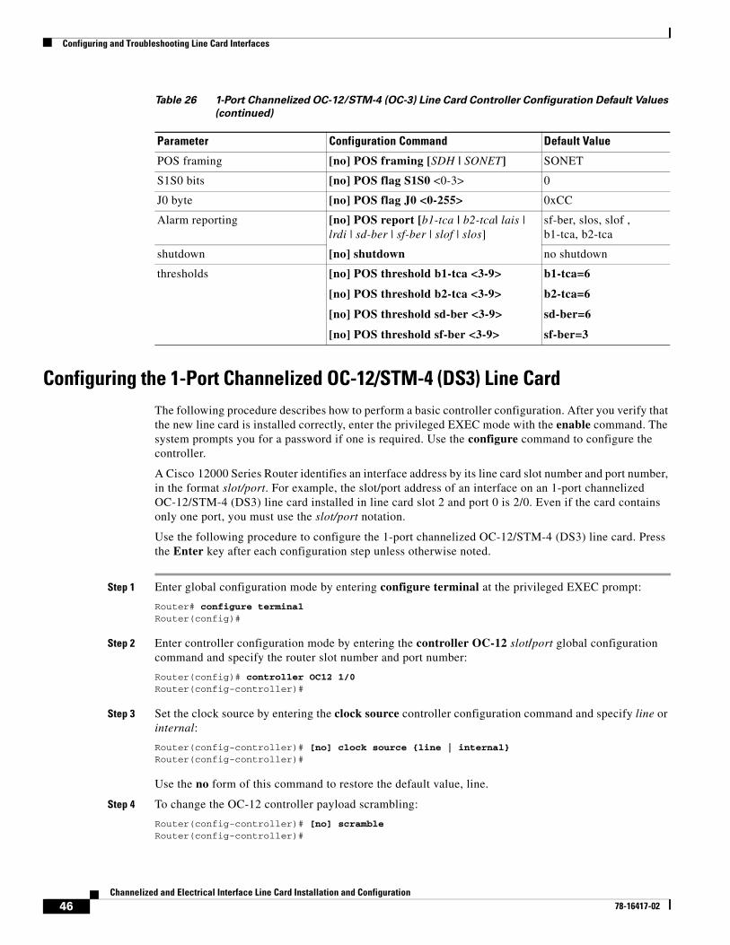
Configuring and Troubleshooting Line Card Interfaces
Configuring the 1-Port Channelized OC-12/STM-4 (DS3) Line CardThe following procedure describes how to perform a basic controller configuration. After you verify that the new line card is installed correctly, enter the privileged EXEC mode with the enable command. The system prompts you for a password if one is required. Use the configure command to configure the controller.
A Cisco 12000 Series Router identifies an interface address by its line card slot number and port number, in the format slot/port. For example, the slot/port address of an interface on an 1-port channelized OC-12/STM-4 (DS3) line card installed in line card slot 2 and port 0 is 2/0. Even if the card contains only one port, you must use the slot/port notation.
Use the following procedure to configure the 1-port channelized OC-12/STM-4 (DS3) line card. Press the Enter key after each configuration step unless otherwise noted.
Step 1 Enter global configuration mode by entering configure terminal at the privileged EXEC prompt:
Router# configure terminalRouter(config)#
Step 2 Enter controller configuration mode by entering the controller OC-12 slot/port global configuration command and specify the router slot number and port number:
Router(config)# controller OC12 1/0Router(config-controller)#
Step 3 Set the clock source by entering the clock source controller configuration command and specify line or internal:
Router(config-controller)# [no] clock source {line | internal}Router(config-controller)#
Use the no form of this command to restore the default value, line.
Step 4 To change the OC-12 controller payload scrambling:
Router(config-controller)# [no] scrambleRouter(config-controller)#
POS framing [no] POS framing [SDH | SONET] SONET
S1S0 bits [no] POS flag S1S0 <0-3> 0
J0 byte [no] POS flag J0 <0-255> 0xCC
Alarm reporting [no] POS report [b1-tca | b2-tca| lais | lrdi | sd-ber | sf-ber | slof | slos]
sf-ber, slos, slof , b1-tca, b2-tca
shutdown [no] shutdown no shutdown
thresholds [no] POS threshold b1-tca <3-9>
[no] POS threshold b2-tca <3-9>
[no] POS threshold sd-ber <3-9>
[no] POS threshold sf-ber <3-9>
b1-tca=6
b2-tca=6
sd-ber=6
sf-ber=3
Table 26 1-Port Channelized OC-12/STM-4 (OC-3) Line Card Controller Configuration Default Values
(continued)
Parameter Configuration Command Default Value
46Channelized and Electrical Interface Line Card Installation and Configuration
78-16417-02
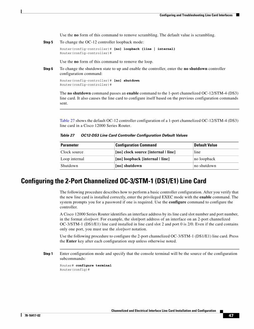
Configuring and Troubleshooting Line Card Interfaces
Use the no form of this command to remove scrambling. The default value is scrambling.
Step 5 To change the OC-12 controller loopback mode:
Router(config-controller)# [no] loopback {line | internal}Router(config-controller)#
Use the no form of this command to remove the loop.
Step 6 To change the shutdown state to up and enable the controller, enter the no shutdown controller configuration command:
Router(config-controller)# [no] shutdownRouter(config-controller)#
The no shutdown command passes an enable command to the 1-port channelized OC-12/STM-4 (DS3) line card. It also causes the line card to configure itself based on the previous configuration commands sent.
Table 27 shows the default OC-12 controller configuration of a 1-port channelized OC-12/STM-4 (DS3) line card in a Cisco 12000 Series Router.
Configuring the 2-Port Channelized OC-3/STM-1 (DS1/E1) Line CardThe following procedure describes how to perform a basic controller configuration. After you verify that the new line card is installed correctly, enter the privileged EXEC mode with the enable command. The system prompts you for a password if one is required. Use the configure command to configure the controller.
A Cisco 12000 Series Router identifies an interface address by its line card slot number and port number, in the format slot/port. For example, the slot/port address of an interface on an 2-port channelized OC-3/STM-1 (DS1/E1) line card installed in line card slot 2 and port 0 is 2/0. Even if the card contains only one port, you must use the slot/port notation.
Use the following procedure to configure the 2-port channelized OC-3/STM-1 (DS1/E1) line card. Press the Enter key after each configuration step unless otherwise noted.
Step 1 Enter configuration mode and specify that the console terminal will be the source of the configuration subcommands:
Router# configure terminal Router(config)#
Table 27 OC12-DS3 Line Card Controller Configuration Default Values
Parameter Configuration Command Default Value
Clock source [no] clock source [internal | line] line
Loop internal [no] loopback [internal | line] no loopback
Shutdown [no] shutdown no shutdown
47Channelized and Electrical Interface Line Card Installation and Configuration
78-16417-02
Configuring and Troubleshooting Line Card Interfaces
Step 2 In global configuration mode, enter the controller configuration mode by entering the controller command and specifying a OC-12/STM-4 interface, as follows:
Router(config)# controller SONET 1/0Router(config-controller)#
Step 3 Set the clock source to line or internal:
Router(config-controller)# [no] clock source {line | internal}
Use the no form of this command to restore the default value, which is line.
Step 4 Change the OC-12/STM-4 controller loopback mode:
Router(config-controller)# [no] loopback {line | internal}
Use the no form of this command to clear the loop setting.
Step 5 Change the framing type for the port:
Router(config-controller)# framing {sonet | sdh}
Note Both OC-3/STM-1 ports should be configured to the same framing type: either both ports configured for SONET, or both ports configured for SDH. The specific restriction applies to mixing E1 and T1 channels on one line card, which is not supported. If you attempt to violate this restriction, the system will display a warning message.
Step 6 Change the shutdown state to up and enable the controller:
Router(config-controller)# [no] shutdown
The no shutdown command passes an enable command to the 2-port channelized OC-3/STM-1 (DS1/E1) line card. It also causes the line card to configure itself based on the current configuration parameter values.
Table 28 shows the default OC-12 controller configuration of a 2-port channelized OC-3/STM-1 (DS1/E1) line card in a Cisco 12000 Series Router.
Table 28 2-Port Channelized OC-3/STM-1 (DS1/E1) Line Card Controller Configuration Default
Values
Parameter Configuration Command Default Value
Framing [no] framing [sdh | sonet] sonet
Clock source [no] clock source [internal | line] line
Loop internal [no] loopback [internal | line] no loopback
Shutdown [no] shutdown no shutdown
48Channelized and Electrical Interface Line Card Installation and Configuration
78-16417-02
Configuring and Troubleshooting Line Card Interfaces
Configuring the 6-Port Channelized T3 (T1) Line CardThe following procedure describes how to perform a basic controller configuration. After you verify that the new line card is installed correctly, enter the privileged EXEC mode with the enable command. The system prompts you for a password if one is required. Use the configure command to configure the controller.
A Cisco 12000 Series Router identifies an interface address by its line card slot number and port number, in the format slot/port. For example, the slot/port address of an interface on an 6-port channelized T3 (T1) line card installed in line card slot 2 and port 0 is 2/0. Even if the card contains only one port, you must use the slot/port notation.
The following sections provide configuration procedures for the T3 Controller and Interface:
• Identifying 6CT3 T1 and T3 Interface Port Numbers and Addresses, page 49
• Configuring the 6-Port Channelized T3 (T1) Line Card Controller, page 49
Identifying 6CT3 T1 and T3 Interface Port Numbers and Addresses
The Cisco 12000 Series Router identifies interface addresses by their line card slot numbers and port numbers, in the format slot/port. For example, the slot/port address of an interface on a6CT3-SMB line card installed in line card slot 1 is 1/0. Even though the card contains only one port, you must use the slot/port notation.
For consistency throughout the following configuration examples for the 6CT3-SMB line card, the T3 controller address is t3 slot/port.
The interface numbering scheme for the 6CT3-SMB line card NxDS0 interfaces is in the form of slot/port/t1:channel-group number
where
– slot refers to the chassis slot where the 6CT3-SMB line card is installed.
– port refers to the physical port on the 6CT3-SMB line card and is always between 0 and 5.
– NxDS0 indicate the interface type.
– T1 lines are numbered 1 to 28.
– NxDS0 channel-groups are numbered 0 to 23. In this document, channel-groups are referred to as channels. There can be up to 24 NxDS0 channels per T1and up to 35 NxDS0 channels per T3.
Note T1 lines on the 6CT3-SMB line card are numbered 1 to 28, rather than the more traditional zero-based scheme (0 to 27) used with other Cisco line card products. This is to ensure consistency with Telco numbering schemes for T1 lines within channelized T3 equipment.
Configuring the 6-Port Channelized T3 (T1) Line Card Controller
Procedures and examples for configuring the T3 controller on the 6-port channelized T3 (T1) line card are presented in the following sections:
• Selecting a T3 Controller, page 50
• Setting the Framing Type for the T3 Controller, page 50
• Specifying the Cable Length, page 50
• Setting the Clock Source for the T3 Controller, page 51
49Channelized and Electrical Interface Line Card Installation and Configuration
78-16417-02
Configuring and Troubleshooting Line Card Interfaces
• Using T3 Controller Loopback Modes, page 51
• Shutting Down the T3 Controller, page 52
• Configuring the T3 Controller to Respond to Remote T3 Loopback Commands, page 53
Selecting a T3 Controller
You must enter the controller T3 slot/port command before any other configuration commands to select the T3 controller you want to configure. The example that follows is for a 6-port channelized T3 (T1) line card in slot 6 of a Cisco 12000 Series Router:
Router# configure terminalEnter configuration commands, one per line. End with CNTL/Z.Router(config)# controller T3 6/0Router(config-controller)#
Setting the Framing Type for the T3 Controller
To specify the framing type, use the controller command framing [c-bit | m23 | auto-detect].
You can set c-bit framing format as follows:
Router(config-controller)# framing c-bitRouter(config-controller)#
You can set m23 framing format as follows:
Router(config-controller)# framing m23Router(config-controller)#
Specifying the Cable Length
For the cablelength value command, user-specified T3 cable lengths are structured into ranges as follows: 0 to 49 feet and 50 to 450 feet. If you enter a cable length value that falls into one of these ranges, the range within which that value applies is used.
Note The configuration is based on feet, not meters.
To specify cable length, use the cablelength value controller configuration command
where
• value is a numeral from 0 to 450 feet (137 meters).
• Default value is 49 feet (15 meters).
An example follows that specifies a cable length of 40 feet (12 meters).
Router(config-controller)# cablelength 40Router(config-controller)#
Note In the preceding example, a cable length of 40 feet (12 meters) is specified, which means that the 0 to 49 (0 to 15 meters) range is used. If you change the cable length to 45 feet (13 meters), then the 0 to 49 (0 to 15 meters) range still applies. Further, if you specify a cable length of 100 feet (30 meters), then change it to 200 feet (60 meters), the 50 to 450 (15 to 137 meters) range applies in each case; therefore, these changes have no effect. Only moving from one range 0 to 49 (0 to 15 meters) to the other range 50 to 450 (15 to137 meters) has an effect. The actual cable-length number you enter is stored in the configuration file.
50Channelized and Electrical Interface Line Card Installation and Configuration
78-16417-02
Configuring and Troubleshooting Line Card Interfaces
Setting the Clock Source for the T3 Controller
To set the selected T3 controller, use the clock source {internal | line} controller configuration command. The default is clock source internal.
• The following example shows how to configure a line clock source:
Router(config)# controller T3 6/0Router(config-controller)# clock source lineRouter(config-controller)#
• The following example shows how to configure an internal clock source:
Router(config)# controller T3 6/0Router(config-controller)# clock source internalRouter(config-controller)#
Using T3 Controller Loopback Modes
To test the T3 controller, use the loopback [local | network | remote] controller configuration commands shown in Table 29. To return the T3 controller to its default condition, use the no form of the command.
• Use the loopback local controller configuration command to diagnose problems with the 6-port channelized T3 (T1) line card when it is isolated from the network cables. The following example is for a 6-port channelized T3 (T1) line card in slot 6 of the Cisco 12000 Series Router:
Router(config)# controller T3 6/0Router(config-controller)# loopback local
• Network loopback loops the T3 line back toward the network and can be used to diagnose problems with cables. The following example shows how to configure the T3 controller for network loopback. The T3 controller is on a 6-port channelized T3 (T1) line card in slot 6 and port 0 of the Cisco 12000 Series Router.
Router(config)# controller T3 6/0Router(config-controller)# loopback network
Table 29 Supported T3 Controller Loopback Modes
Loopback modesConfiguration Mode Command
Diagnostic or local loopback
loopback local Router(config-controller)# loopback local
Network loopback modes
loopback network
Router(config-controller)# loopback network
Remote T3 loopback loopback remote
Router(config-controller)# loopback remote
equipment network loopback
equipment network loopback
Router(config-controller)# equipment network loopback
Default value default value Router(config-controller)# no loopback
51Channelized and Electrical Interface Line Card Installation and Configuration
78-16417-02
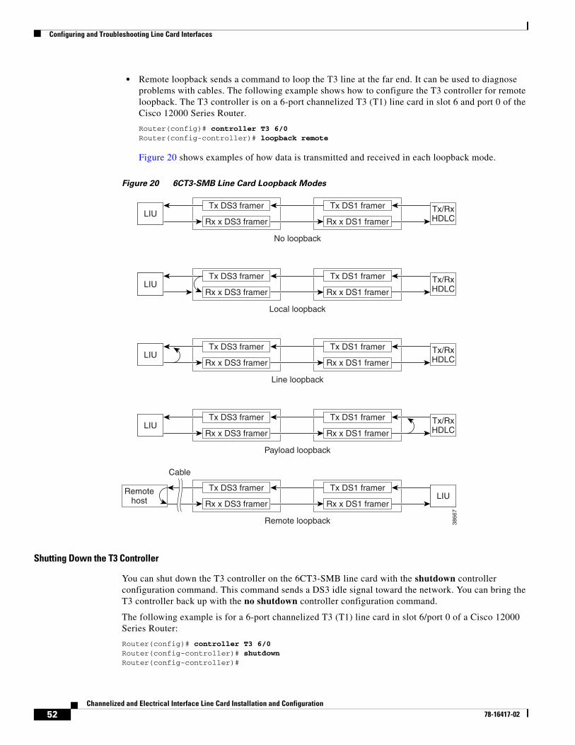
Configuring and Troubleshooting Line Card Interfaces
• Remote loopback sends a command to loop the T3 line at the far end. It can be used to diagnose problems with cables. The following example shows how to configure the T3 controller for remote loopback. The T3 controller is on a 6-port channelized T3 (T1) line card in slot 6 and port 0 of the Cisco 12000 Series Router.
Router(config)# controller T3 6/0Router(config-controller)# loopback remote
Figure 20 shows examples of how data is transmitted and received in each loopback mode.
Figure 20 6CT3-SMB Line Card Loopback Modes
Shutting Down the T3 Controller
You can shut down the T3 controller on the 6CT3-SMB line card with the shutdown controller configuration command. This command sends a DS3 idle signal toward the network. You can bring the T3 controller back up with the no shutdown controller configuration command.
The following example is for a 6-port channelized T3 (T1) line card in slot 6/port 0 of a Cisco 12000 Series Router:
Router(config)# controller T3 6/0Router(config-controller)# shutdownRouter(config-controller)#
Tx/RxHDLC
Tx DS1 framer
Rx x DS1 framer
3866
7
No loopback
LIUTx DS3 framer
Rx x DS3 framer
Tx/RxHDLC
Tx DS1 framer
Rx x DS1 framerLIU
Tx DS3 framer
Rx x DS3 framer
Local loopback
Tx/RxHDLC
Tx DS1 framer
Rx x DS1 framerLIU
Tx DS3 framer
Rx x DS3 framer
Line loopback
Tx/RxHDLC
Tx DS1 framer
Rx x DS1 framerLIU
Tx DS3 framer
Rx x DS3 framer
Payload loopback
Tx DS1 framer
Rx x DS1 framer
Remotehost
Tx DS3 framer
Rx x DS3 framer
Remote loopback
Cable
LIU
52Channelized and Electrical Interface Line Card Installation and Configuration
78-16417-02
Configuring and Troubleshooting Line Card Interfaces
Configuring the T3 Controller to Respond to Remote T3 Loopback Commands
This section explains how to use the equipment [customer|network] loopback controller configuration command.
To enable the 6-port channelized T3 (T1) line card to respond to remote T3 loopback commands from the remote T3 equipment, use the equipment customer loopback command.
Router(config-controller)# equipment customer loopbackRouter(config-controller)#
or
To enable the 6-port channelized T3 (T1) line card to ignore remote T3 loopback commands, use the equipment network loopback command.
Router(config-controller)# equipment network loopbackRouter(config-controller)#
Note Remote loopbacks are only available when you use c-bit parity framing.
Configuring the 6-Port and 12-Port DS3 Line Card ControllerThis section provides basic information to configure an interface and to specify IP routing. You can also enter other configuration commands and options, depending on the requirements of your system. To configure the 6-port and 12-port DS3 line card interfaces, you must identify the router slot where the line card is installed (for example, slot 7). Use the show diag EXEC command to verify that the system recognizes the line card.
Router# show diag 2 SLOT 2 (RP/LC 2 ):6 Port Packet over DS3Router#
(Remainder of displayed text omitted from example.)
If you know that there is more than one 6-port or 12-port DS3 line card installed in the router, use the show diag summary EXEC command to see the types of line cards that are installed in all of the router slots. The following output shows a 6-port DS3 line card in slot 2 and a 12-port DS3 line card in slot 6.
Router# show diag summSLOT 0 (RP/LC 0 ):1 Port Packet Over SONET OC-12c/STM-4c Single ModeSLOT 1 (RP/LC 1 ):1 port SONET OC12 channelized to DS3 Single ModeSLOT 2 (RP/LC 2 ):6 Port Packet over DS3 <<<<<----see DS3 line cardSLOT 4 (RP/LC 4 ):4 Port Packet Over SONET OC-3c/STM-1 Single ModeSLOT 6 (RP/LC 6 ):12 Port Packet over DS3 <<<<<----see DS3 line cardRouter#
If you want to address a specifc 6-port or 12-port DS3 line card interface, refer to interface slot 2 or interface slot 6, as shown in the previous output example.
If you want to address a specifc port on the 6-port or 12-port DS3 line card, refer to the router slot number and one of the serial interface port numbers.
Based on the previous output example:
• To address the 6-port DS3 line card, which has six ports, in slot 2, the valid port numbers are 0 through 5, inclusive. The serial interface slot/port configuration format range is 2/0 through 2/5.
53Channelized and Electrical Interface Line Card Installation and Configuration
78-16417-02
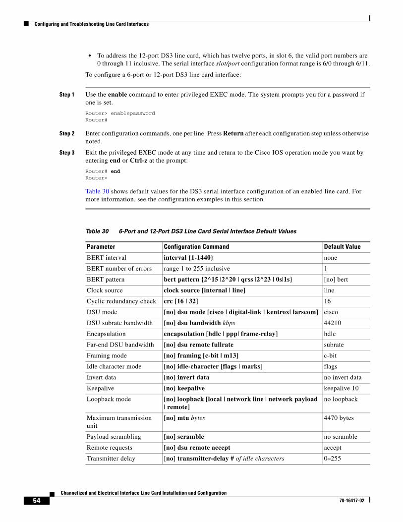
Configuring and Troubleshooting Line Card Interfaces
• To address the 12-port DS3 line card, which has twelve ports, in slot 6, the valid port numbers are 0 through 11 inclusive. The serial interface slot/port configuration format range is 6/0 through 6/11.
To configure a 6-port or 12-port DS3 line card interface:
Step 1 Use the enable command to enter privileged EXEC mode. The system prompts you for a password if one is set.
Router> enablepasswordRouter#
Step 2 Enter configuration commands, one per line. Press Return after each configuration step unless otherwise noted.
Step 3 Exit the privileged EXEC mode at any time and return to the Cisco IOS operation mode you want by entering end or Ctrl-z at the prompt:
Router# endRouter>
Table 30 shows default values for the DS3 serial interface configuration of an enabled line card. For more information, see the configuration examples in this section.
Table 30 6-Port and 12-Port DS3 Line Card Serial Interface Default Values
Parameter Configuration Command Default Value
BERT interval interval {1-1440} none
BERT number of errors range 1 to 255 inclusive 1
BERT pattern bert pattern {2^15 |2^20 | qrss |2^23 | 0s|1s} [no] bert
Clock source clock source [internal | line] line
Cyclic redundancy check crc [16 | 32] 16
DSU mode [no] dsu mode [cisco | digital-link | kentrox| larscom] cisco
DSU subrate bandwidth [no] dsu bandwidth kbps 44210
Encapsulation encapsulation [hdlc | ppp| frame-relay] hdlc
Far-end DSU bandwidth [no] dsu remote fullrate subrate
Framing mode [no] framing [c-bit | m13] c-bit
Idle character mode [no] idle-character [flags | marks] flags
Invert data [no] invert data no invert data
Keepalive [no] keepalive keepalive 10
Loopback mode [no] loopback [local | network line | network payload | remote]
no loopback
Maximum transmission unit
[no] mtu bytes 4470 bytes
Payload scrambling [no] scramble no scramble
Remote requests [no] dsu remote accept accept
Transmitter delay [no] transmitter-delay # of idle characters 0–255
54Channelized and Electrical Interface Line Card Installation and Configuration
78-16417-02
Configuring and Troubleshooting Line Card Interfaces
Configuring the 6-Port and 12-Port E3 Line Card ControllerThis section provides basic information to configure an interface and to specify IP routing. You can also enter other configuration commands and options, depending on the requirements of your system. To configure the 6-port and 12-port E3 line cards interfaces, you must identify the router slot where the line card is installed (for example, slot 7). Use the show diag EXEC command to verify that the system recognizes the line card.
Router# show diag 2 SLOT 2 (RP/LC 2 ):6 Port Packet over E3Router#
(Remainder of displayed text is omitted from example.)
If you know that there is more than one 6-port or 12-port E3 line card installed in the router, use the show diag summary EXEC command to display the types of line cards that are installed in all the router slots. The following output shows a 6-port E3 line card in slot 2 and a 12-port E3 line card in slot 6.
Router# show diag summSLOT 0 (RP/LC 0 ):1 Port Packet Over SONET OC-12c/STM-4c Single ModeSLOT 1 (RP/LC 1 ):1 port SONET OC12 channelized to E3 Single ModeSLOT 2 (RP/LC 2 ):6 Port Packet over E3 <<<<<----see E3 line cardSLOT 4 (RP/LC 4 ):4 Port Packet Over SONET OC-3c/STM-1 Single ModeSLOT 6 (RP/LC 6 ):12 Port Packet over E3 <<<<<----see E3 line cardRouter#
If you want to address a specific 6-port or 12-port E3 line card interface, refer to interface slot 2 or interface slot 6, as shown in the previous output example.
If you want to address a specific port on the 6-port or 12-port E3 line card, refer to the router slot number and one of the serial interface port numbers.
Based on the previous output example:
• To address the 6-port E3 line card, which has six ports, in slot 2, the valid port numbers are 0 through 5, inclusive. The serial interface slot/port configuration format range is 2/0 through 2/5.
• To address the 12-port E3 line card, which has twelve ports, in slot 6, the valid port numbers are 0 through 11, inclusive. The serial interface slot/port configuration format range is 6/0 through 6/11.
To configure a 6-port or 12-port E3 line card interface:
Step 1 Use the enable command to enter privileged EXEC mode. The system prompts you for a password if one is set.
Router> enablepasswordRouter#
Step 2 Enter configuration commands, one per line. Press Return after each configuration step unless otherwise noted.
Step 3 Exit the privileged EXEC mode at any time and return to the Cisco IOS operation mode you want by entering end or Ctrl-z at the prompt:
Router# endRouter>
Table 30 shows default values for the E3 serial interface configuration of an enabled line card. For more information, see the configuration examples in this section.
55Channelized and Electrical Interface Line Card Installation and Configuration
78-16417-02
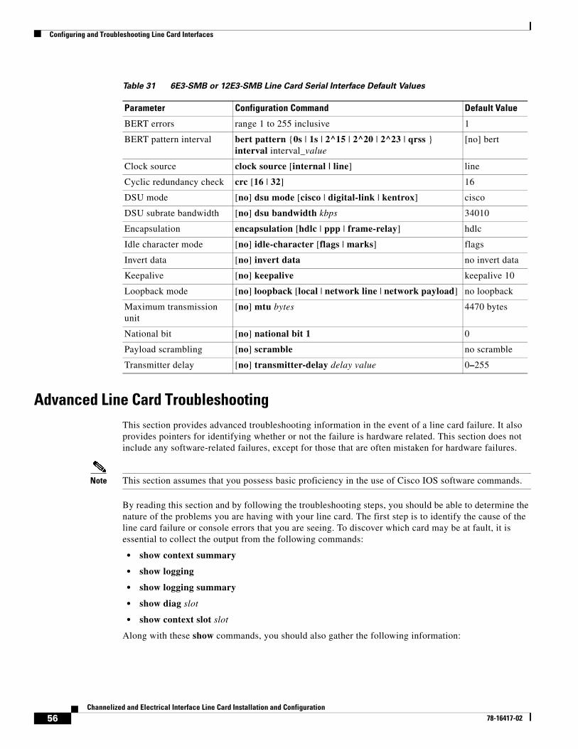
Configuring and Troubleshooting Line Card Interfaces
Advanced Line Card TroubleshootingThis section provides advanced troubleshooting information in the event of a line card failure. It also provides pointers for identifying whether or not the failure is hardware related. This section does not include any software-related failures, except for those that are often mistaken for hardware failures.
Note This section assumes that you possess basic proficiency in the use of Cisco IOS software commands.
By reading this section and by following the troubleshooting steps, you should be able to determine the nature of the problems you are having with your line card. The first step is to identify the cause of the line card failure or console errors that you are seeing. To discover which card may be at fault, it is essential to collect the output from the following commands:
• show context summary
• show logging
• show logging summary
• show diag slot
• show context slot slot
Along with these show commands, you should also gather the following information:
Table 31 6E3-SMB or 12E3-SMB Line Card Serial Interface Default Values
Parameter Configuration Command Default Value
BERT errors range 1 to 255 inclusive 1
BERT pattern interval bert pattern {0s | 1s | 2^15 | 2^20 | 2^23 | qrss } interval interval_value
[no] bert
Clock source clock source [internal | line] line
Cyclic redundancy check crc [16 | 32] 16
DSU mode [no] dsu mode [cisco | digital-link | kentrox] cisco
DSU subrate bandwidth [no] dsu bandwidth kbps 34010
Encapsulation encapsulation [hdlc | ppp | frame-relay] hdlc
Idle character mode [no] idle-character [flags | marks] flags
Invert data [no] invert data no invert data
Keepalive [no] keepalive keepalive 10
Loopback mode [no] loopback [local | network line | network payload] no loopback
Maximum transmission unit
[no] mtu bytes 4470 bytes
National bit [no] national bit 1 0
Payload scrambling [no] scramble no scramble
Transmitter delay [no] transmitter-delay delay value 0–255
56Channelized and Electrical Interface Line Card Installation and Configuration
78-16417-02
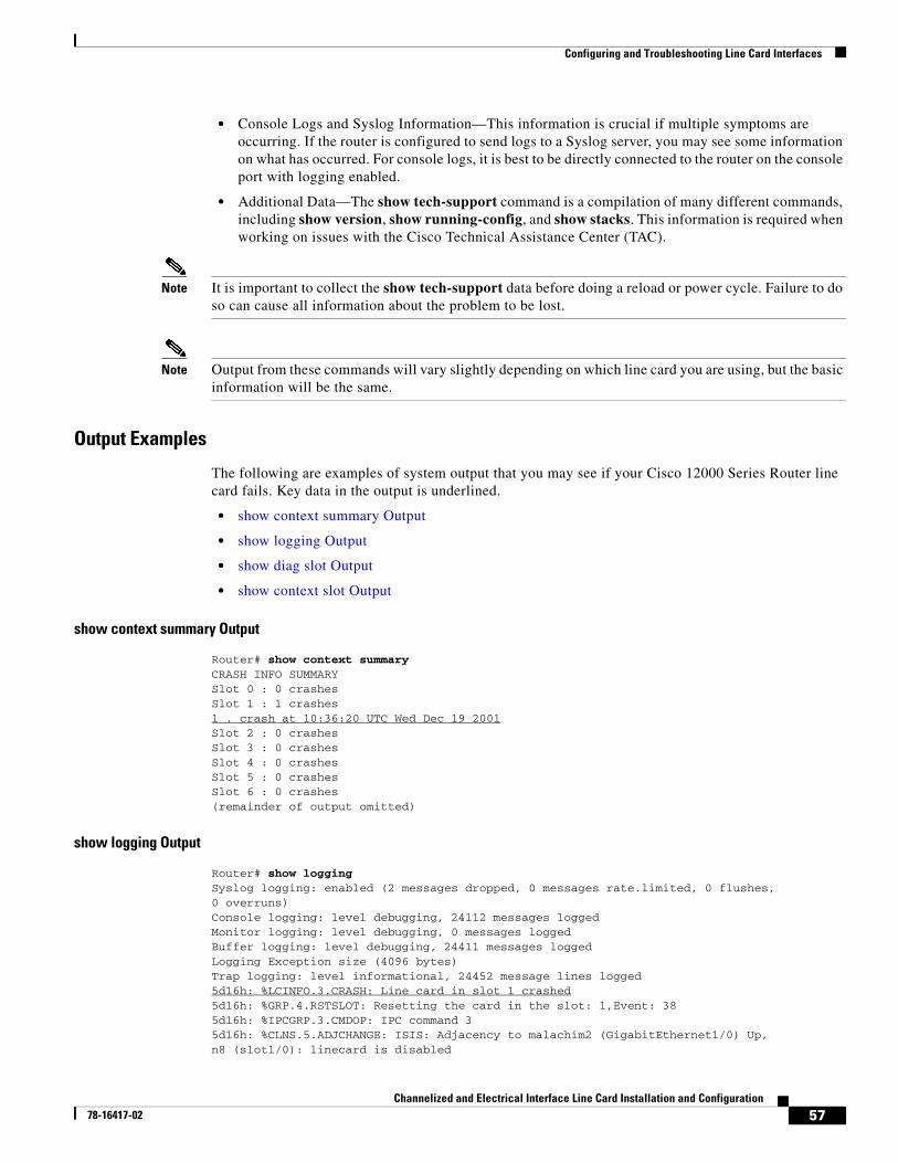
Configuring and Troubleshooting Line Card Interfaces
• Console Logs and Syslog Information—This information is crucial if multiple symptoms are occurring. If the router is configured to send logs to a Syslog server, you may see some information on what has occurred. For console logs, it is best to be directly connected to the router on the console port with logging enabled.
• Additional Data—The show tech-support command is a compilation of many different commands, including show version, show running-config, and show stacks. This information is required when working on issues with the Cisco Technical Assistance Center (TAC).
Note It is important to collect the show tech-support data before doing a reload or power cycle. Failure to do so can cause all information about the problem to be lost.
Note Output from these commands will vary slightly depending on which line card you are using, but the basic information will be the same.
Output Examples
The following are examples of system output that you may see if your Cisco 12000 Series Router line card fails. Key data in the output is underlined.
• show context summary Output
• show logging Output
• show diag slot Output
• show context slot Output
show context summary Output
Router# show context summaryCRASH INFO SUMMARYSlot 0 : 0 crashesSlot 1 : 1 crashes1 . crash at 10:36:20 UTC Wed Dec 19 2001Slot 2 : 0 crashesSlot 3 : 0 crashesSlot 4 : 0 crashesSlot 5 : 0 crashesSlot 6 : 0 crashes(remainder of output omitted)
show logging Output
Router# show loggingSyslog logging: enabled (2 messages dropped, 0 messages rate.limited, 0 flushes,0 overruns)Console logging: level debugging, 24112 messages loggedMonitor logging: level debugging, 0 messages loggedBuffer logging: level debugging, 24411 messages loggedLogging Exception size (4096 bytes)Trap logging: level informational, 24452 message lines logged5d16h: %LCINFO.3.CRASH: Line card in slot 1 crashed5d16h: %GRP.4.RSTSLOT: Resetting the card in the slot: 1,Event: 385d16h: %IPCGRP.3.CMDOP: IPC command 35d16h: %CLNS.5.ADJCHANGE: ISIS: Adjacency to malachim2 (GigabitEthernet1/0) Up,n8 (slot1/0): linecard is disabled
57Channelized and Electrical Interface Line Card Installation and Configuration
78-16417-02
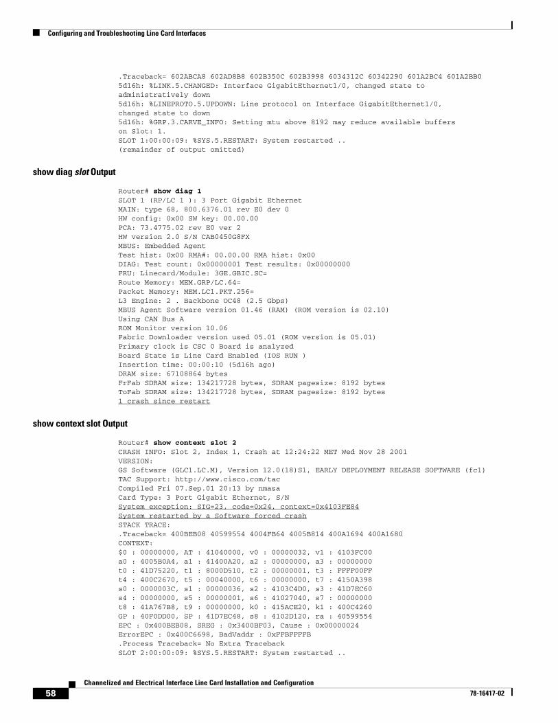
Configuring and Troubleshooting Line Card Interfaces
.Traceback= 602ABCA8 602AD8B8 602B350C 602B3998 6034312C 60342290 601A2BC4 601A2BB05d16h: %LINK.5.CHANGED: Interface GigabitEthernet1/0, changed state toadministratively down5d16h: %LINEPROTO.5.UPDOWN: Line protocol on Interface GigabitEthernet1/0,changed state to down5d16h: %GRP.3.CARVE_INFO: Setting mtu above 8192 may reduce available bufferson Slot: 1.SLOT 1:00:00:09: %SYS.5.RESTART: System restarted ..(remainder of output omitted)
show diag slot Output
Router# show diag 1SLOT 1 (RP/LC 1 ): 3 Port Gigabit EthernetMAIN: type 68, 800.6376.01 rev E0 dev 0HW config: 0x00 SW key: 00.00.00PCA: 73.4775.02 rev E0 ver 2HW version 2.0 S/N CAB0450G8FXMBUS: Embedded AgentTest hist: 0x00 RMA#: 00.00.00 RMA hist: 0x00DIAG: Test count: 0x00000001 Test results: 0x00000000FRU: Linecard/Module: 3GE.GBIC.SC=Route Memory: MEM.GRP/LC.64=Packet Memory: MEM.LC1.PKT.256=L3 Engine: 2 . Backbone OC48 (2.5 Gbps)MBUS Agent Software version 01.46 (RAM) (ROM version is 02.10)Using CAN Bus AROM Monitor version 10.06Fabric Downloader version used 05.01 (ROM version is 05.01)Primary clock is CSC 0 Board is analyzedBoard State is Line Card Enabled (IOS RUN )Insertion time: 00:00:10 (5d16h ago)DRAM size: 67108864 bytesFrFab SDRAM size: 134217728 bytes, SDRAM pagesize: 8192 bytesToFab SDRAM size: 134217728 bytes, SDRAM pagesize: 8192 bytes1 crash since restart
show context slot Output
Router# show context slot 2CRASH INFO: Slot 2, Index 1, Crash at 12:24:22 MET Wed Nov 28 2001VERSION:GS Software (GLC1.LC.M), Version 12.0(18)S1, EARLY DEPLOYMENT RELEASE SOFTWARE (fc1)TAC Support: http://www.cisco.com/tacCompiled Fri 07.Sep.01 20:13 by nmasaCard Type: 3 Port Gigabit Ethernet, S/NSystem exception: SIG=23, code=0x24, context=0x4103FE84System restarted by a Software forced crashSTACK TRACE:.Traceback= 400BEB08 40599554 4004FB64 4005B814 400A1694 400A1680CONTEXT:$0 : 00000000, AT : 41040000, v0 : 00000032, v1 : 4103FC00a0 : 4005B0A4, a1 : 41400A20, a2 : 00000000, a3 : 00000000t0 : 41D75220, t1 : 8000D510, t2 : 00000001, t3 : FFFF00FFt4 : 400C2670, t5 : 00040000, t6 : 00000000, t7 : 4150A398s0 : 0000003C, s1 : 00000036, s2 : 4103C4D0, s3 : 41D7EC60s4 : 00000000, s5 : 00000001, s6 : 41027040, s7 : 00000000t8 : 41A767B8, t9 : 00000000, k0 : 415ACE20, k1 : 400C4260GP : 40F0DD00, SP : 41D7EC48, s8 : 4102D120, ra : 40599554EPC : 0x400BEB08, SREG : 0x3400BF03, Cause : 0x00000024ErrorEPC : 0x400C6698, BadVaddr : 0xFFBFFFFB.Process Traceback= No Extra TracebackSLOT 2:00:00:09: %SYS.5.RESTART: System restarted ..
58Channelized and Electrical Interface Line Card Installation and Configuration
78-16417-02
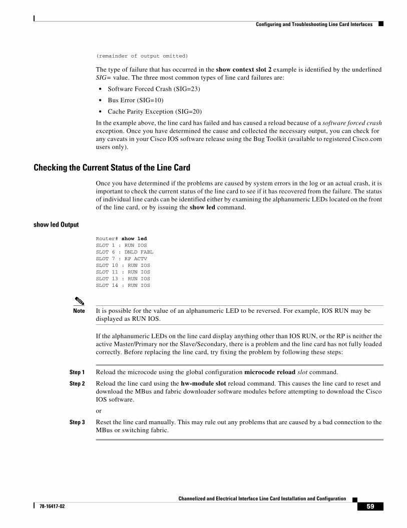
Configuring and Troubleshooting Line Card Interfaces
(remainder of output omitted)
The type of failure that has occurred in the show context slot 2 example is identified by the underlined SIG= value. The three most common types of line card failures are:
• Software Forced Crash (SIG=23)
• Bus Error (SIG=10)
• Cache Parity Exception (SIG=20)
In the example above, the line card has failed and has caused a reload because of a software forced crash exception. Once you have determined the cause and collected the necessary output, you can check for any caveats in your Cisco IOS software release using the Bug Toolkit (available to registered Cisco.com users only).
Checking the Current Status of the Line Card
Once you have determined if the problems are caused by system errors in the log or an actual crash, it is important to check the current status of the line card to see if it has recovered from the failure. The status of individual line cards can be identified either by examining the alphanumeric LEDs located on the front of the line card, or by issuing the show led command.
show led Output
Router# show ledSLOT 1 : RUN IOSSLOT 6 : DNLD FABLSLOT 7 : RP ACTVSLOT 10 : RUN IOSSLOT 11 : RUN IOSSLOT 13 : RUN IOSSLOT 14 : RUN IOS
Note It is possible for the value of an alphanumeric LED to be reversed. For example, IOS RUN may be displayed as RUN IOS.
If the alphanumeric LEDs on the line card display anything other than IOS RUN, or the RP is neither the active Master/Primary nor the Slave/Secondary, there is a problem and the line card has not fully loaded correctly. Before replacing the line card, try fixing the problem by following these steps:
Step 1 Reload the microcode using the global configuration microcode reload slot command.
Step 2 Reload the line card using the hw-module slot reload command. This causes the line card to reset and download the MBus and fabric downloader software modules before attempting to download the Cisco IOS software.
or
Step 3 Reset the line card manually. This may rule out any problems that are caused by a bad connection to the MBus or switching fabric.
59Channelized and Electrical Interface Line Card Installation and Configuration
78-16417-02
Configuring and Troubleshooting Line Card Interfaces
Fabric Ping Failure
Fabric ping failures occur when either a line card or the secondary RP fails to respond to a fabric ping request from the primary RP over the switch fabric. Such failures are a problem symptom that should be investigated. They are indicated by the following error messages:
%GRP-3-FABRIC_UNI: Unicast send timed out (1)%GRP-3-COREDUMP: Core dump incident on slot 1, error: Fabric ping failure%LCINFO-3-CRASH: Line card in slot 1 crashed
You can find more information about this issue on Cisco.com in the Troubleshooting Fabric Ping Timeouts and Failures on the Cisco 12000 Series Internet Router publication.
Error Messages
If you receive any error message related to a line card, you can use the Error Message Decoder Tool (on Cisco.com) to find the meaning of this error message. Some errors point to a hardware issue, while others indicate a Cisco IOS software caveat or a hardware issue on another part of the router. This publication does not cover all these messages.
Note Some messages related to Cisco Express Forwarding (CEF) and Inter Process-Communication (IPC) are explained on Cisco.com in the Troubleshooting CEF-Related Error Messages publication.
Line Card Alarm and Event Detection
This section assumes that you are familiar with SONET/SDH alarm and signal events for SONET line cards and DS3/E3 alarms and line states for DS3/E3 line cards. Your line card does not have an LED for alarm and event detection, but you can enter the show controllers EXEC command to verify whether the alarm and event detection messages are active or inactive. Most alarm and event detection messages are short-lived, because if problems occur, the line card clears the error condition, but records the event to verify line card operation status.
To display SONET alarms, use the show controllers sonet command; to display DS3 or E3 alarms, use the show controllers serial command.
The output from the show controllers serial slot/port EXEC command sends messages about the following types of alarms and events:
• AIS (Alarm Indication Signal)
• LOF (Loss of Frame)
• LOS (Loss of Signal)
• OOF (Out of Frame)
• RAI (Remote Alarm Indication)
The output also indicates whether the alarm or event originates from the local end connector or the remote end connector.
Some of the alarm and signal events for the SONET line cards are enabled for reporting by default. Others can be enabled individually. What the show controllers sonet privileged EXEC command displays depends on the configuration of the SONET port.
60Channelized and Electrical Interface Line Card Installation and Configuration
78-16417-02
Configuring and Troubleshooting Line Card Interfaces
The following partial output example from the show controllers sonet privileged EXEC command shows alarm and event information for the second SONET controller in slot 3 of a Cisco 12000 Series Router (4-port channelized OC-12/STM-4 ISE line card):
router# show controllers sonet 3/1SONET3/1 Current state of the controller is up Framing is SONET Clock source is INTERNAL, Loopback is NONE
SECTION LOF = 0 LOS = 0 BIP(B1) = 0LINE AIS = 0 RDI = 0 FEBE = 147 BIP(B2) = 0
Active Defects:NoneActive Alarms: NoneAlarm reporting enabled for:SF SLOS SLOF B1-TCA B2-TCA B3-TCA
APS COAPS = 0 PSBF = 0 State:PSBF_state = False ais_shut = FALSE Rx(K1/K2):00/00BER thresholds: SF = 10e-3 SD = 10e-6TCA thresholds: B1 = 10e-6 B2 = 10e-6
Optical Power MonitoringLaser Bias = 33.6 mAReceiver Power = -5.80 dBm (+/- 2 dBm)
Line Card Diagnostics Using Cisco IOS Software Releases Prior to 12.0(22)S
Note Output from this procedure will vary slightly depending on which line card you are using, but the basic information will be the same.
Line card field diagnostic software is bundled with the main Cisco IOS software to enable you to test whether a suspect line card is faulty. To use this feature, you must be in privileged enable mode, and issue the diag slot [verbose] command.
While the diagnostic test is running, the line card does not function normally and cannot pass any traffic for the duration of the testing. Without the verbose keyword, the command provides a truncated output message. When communicating with the Cisco TAC, the verbose mode is helpful in identifying specific problems. The output of the diagnostic test without the verbose command appears like the following example:
Router#diag 3 Running DIAG config checkRunning Diags will halt ALL activity on the requested slot[confirm]Router#Launching a Field Diagnostic for slot 3Downloading diagnostic tests to slot 3 (timeout set to 600 sec.)*Nov 18 22:20:40.237: %LINK.5.CHANGED: Interface GigabitEthernet3/0,changed state to administratively downField Diag download COMPLETE for slot 3FD 3> *****************************************************
61Channelized and Electrical Interface Line Card Installation and Configuration
78-16417-02
Configuring and Troubleshooting Line Card Interfaces
FD 3> GSR Field Diagnostics V4.0FD 3> Compiled by award on Thu May 18 13:43:04 PDT 2000FD 3> view: award.conn_isp.FieldDiagReleaseFD 3> *****************************************************FD 3> BFR_CARD_TYPE_1P_GE testing...FD 3> running in slot 3 (83 tests)Executing all diagnostic tests in slot 3(total/indiv. timeout set to 600/200 sec.)Field Diagnostic: ****TEST FAILURE**** slot 3: last test run 51,Fabric Packet Loopback, error 3Shutting down diags in slot 3slot 3 done, will not reload automatically
The line card reloads automatically only after passing the test. In the example above, the line card failed the test and did not reload automatically. You can manually reload the line card by using the hw-module slot slot reload command.
Field diagnostic results are stored in an EEPROM on the line card. It is possible to view the results of the last diagnostic test performed on the line card by executing the diag slot previous command.
There are some caveats that exist that cause diagnostic tests to fail, even though the line card is not faulty. As a precaution, if the line card fails and had been replaced previously, you should review this output with the Cisco TAC.
Line Card Diagnostics Using Cisco IOS Software Release 12.0(22)S and Later
Note Output from this procedure will vary slightly depending on which line card you are using, but the basic information will be the same.
Line card field diagnostic software is designed to identify any faulty line card within a Cisco 12000 Series Router. Before Cisco IOS Software Release 12.0(22)S, the field diagnostic software was imbedded within the Cisco IOS software. Starting with Cisco IOS Software Release 12.0(22)S, this software is unbundled from the main image and must be downloaded from Cisco.com using the IOS Upgrade Planner.
Cisco initiated this change to accommodate users with 20-MB Flash memory cards. Field diagnostics are now stored and maintained as a separate image under the following name:
c12k-fdiagsbflc-mz-xxx-xx.s (where xxx-xx is the version number)
This image must be available on a separate Flash memory card, Flash disk, or TFTP boot server in order to load line card field diagnostics. The latest version is always available on Cisco.com. RP and fabric tests remain embedded within the main Cisco IOS software image.
While the diagnostic test is running, the line card does not function normally and cannot pass any traffic for the duration of the testing (5 to 20 minutes depending upon the complexity of the line card). Without the verbose keyword, the command provides a truncated output message. When communicating with the Cisco TAC, the verbose mode is helpful in identifying specific problems. The output of the diagnostic test without the verbose command appears like the following example:
Router# diag 7 tftp://223.255.254.254/diagnostic/award/c12k.fdiagsbflc.mz.120-25.sRunning DIAG config checkFabric Download for Field Diags chosen: If timeout occurs, try 'mbus' option.Runnning Diags will halt ALL activity on the requested slot. [confirm]Launching a Field Diagnostic for slot 7Downloading diagnostic tests to slot 7 via fabric (timeout set to 300 sec.)
62Channelized and Electrical Interface Line Card Installation and Configuration
78-16417-02
Line Card Memory
5d20h: %GRP.4.RSTSLOT: Resetting the card in the slot: 7,Event:EV_ADMIN_FDIAGLoading diagnostic/award/c12k.fdiagsbflc.mz.120-25.s from 223.255.254.254(via Ethernet0): !!!!!!!!!!!!!!!!!!!!!!!!!!!!!!!!!!!!!!!!!!!!!!!!!5d20h: Downloading diags from tftp file tftp://223.255.254.254/diagnostic/award/c12k.fdiagsbflc.mz.120-25.s!!!!!!!!!!!!!!!!!!!!!!!!!!!!!!!!!!!!!!!!!!!!!!!![OK . 13976524 bytes]FD 7> *****************************************************FD 7> GSR Field Diagnostics V6.05FD 7> Compiled by award on Tue Jul 30 13:00:41 PDT 2002FD 7> view: award.conn_isp.FieldDiagReleaseFD 7> *****************************************************Executing all diagnostic tests in slot 7(total/indiv. timeout set to 2000/600 sec.)FD 7> BFR_CARD_TYPE_OC12_4P_POS testing...FD 7> Available test types 2FD 7> 1FD 7> Completed f_diags_board_discovery() (0x1)FD 7> Test list selection received: Test ID 1, Device 0FD 7> running in slot 7 (30 tests from test list ID 1)FD 7> Skipping MBUS_FDIAG command from slot 2FD 7> Just into idle stateField Diagnostic ****PASSED**** for slot 7Shutting down diags in slot 7Board will reload(remainder of output omitted)
The line card reloads automatically only after passing the test. If the line card fails the test, it will not reload automatically. You can manually reload the line card by using the hw-module slot slot reload command.
Field diagnostic results are stored in an electrically erasable programmable read-only memory (EEPROM) on the line card. It is possible to view the results of the last diagnostic test performed on the line card by executing the diag slot previous command.
There are some caveats that exist that cause diagnostic tests to fail, even though the line card is not faulty. As a precaution, if the line card fails and had been replaced previously, you should review this output with the Cisco TAC.
Line Card Memory
Caution The user serviceability of memory modules varies from line card to line card. Read this section carefully before attempting to remove or install any line card memory module.
The channelized and electrical interface line cards include the following types of memory:
• Route memory
• Packet memory
• Pointer look-up (PLU) memory (not user serviceable)
• Table look-up (TLU) memory (not user serviceable)
Line card memory configurations and memory socket locations differ, depending on the line card engine type. Table 32 lists the channelized and electrical interface line card engine types.
63Channelized and Electrical Interface Line Card Installation and Configuration
78-16417-02
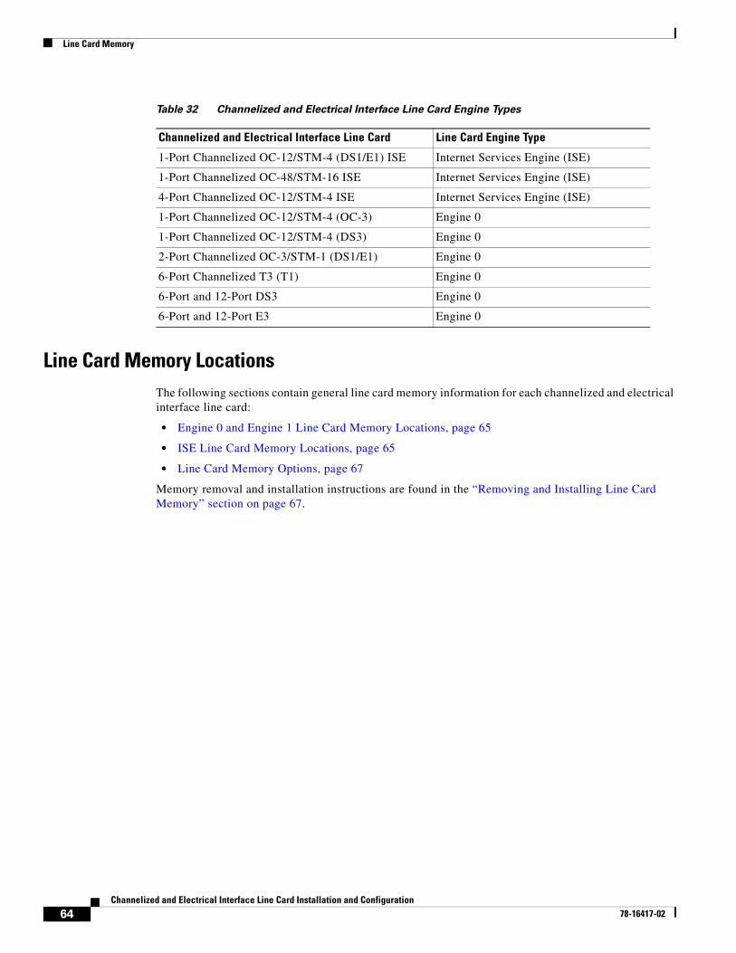
Line Card Memory
Line Card Memory LocationsThe following sections contain general line card memory information for each channelized and electrical interface line card:
• Engine 0 and Engine 1 Line Card Memory Locations, page 65
• ISE Line Card Memory Locations, page 65
• Line Card Memory Options, page 67
Memory removal and installation instructions are found in the “Removing and Installing Line Card Memory” section on page 67.
Table 32 Channelized and Electrical Interface Line Card Engine Types
Channelized and Electrical Interface Line Card Line Card Engine Type
1-Port Channelized OC-12/STM-4 (DS1/E1) ISE Internet Services Engine (ISE)
1-Port Channelized OC-48/STM-16 ISE Internet Services Engine (ISE)
4-Port Channelized OC-12/STM-4 ISE Internet Services Engine (ISE)
1-Port Channelized OC-12/STM-4 (OC-3) Engine 0
1-Port Channelized OC-12/STM-4 (DS3) Engine 0
2-Port Channelized OC-3/STM-1 (DS1/E1) Engine 0
6-Port Channelized T3 (T1) Engine 0
6-Port and 12-Port DS3 Engine 0
6-Port and 12-Port E3 Engine 0
64Channelized and Electrical Interface Line Card Installation and Configuration
78-16417-02
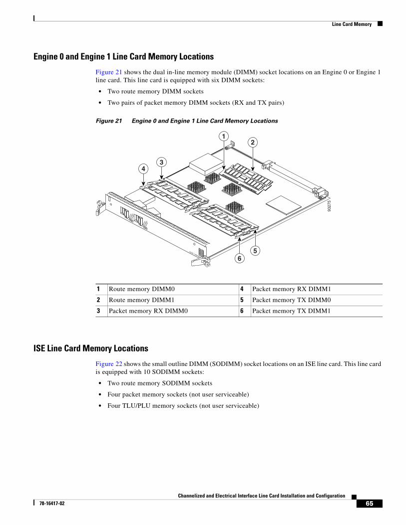
Line Card Memory
Engine 0 and Engine 1 Line Card Memory Locations
Figure 21 shows the dual in-line memory module (DIMM) socket locations on an Engine 0 or Engine 1 line card. This line card is equipped with six DIMM sockets:
• Two route memory DIMM sockets
• Two pairs of packet memory DIMM sockets (RX and TX pairs)
Figure 21 Engine 0 and Engine 1 Line Card Memory Locations
ISE Line Card Memory Locations
Figure 22 shows the small outline DIMM (SODIMM) socket locations on an ISE line card. This line card is equipped with 10 SODIMM sockets:
• Two route memory SODIMM sockets
• Four packet memory sockets (not user serviceable)
• Four TLU/PLU memory sockets (not user serviceable)
1 Route memory DIMM0 4 Packet memory RX DIMM1
2 Route memory DIMM1 5 Packet memory TX DIMM0
3 Packet memory RX DIMM0 6 Packet memory TX DIMM1
ACTIV
E
0 CARR
IER
RX PK
T
ACTIV
E
1 CARR
IER
RX PK
T
Q OC-3/STM-POS
9327
5
21
56
34
65Channelized and Electrical Interface Line Card Installation and Configuration
78-16417-02
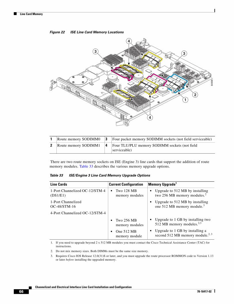
Line Card Memory
Figure 22 ISE Line Card Memory Locations
There are two route memory sockets on ISE (Engine 3) line cards that support the addition of route memory modules. Table 33 describes the various memory upgrade options.
1 Route memory SODIMM0 3 Four packet memory SODIMM sockets (not field serviceable)
2 Route memory SODIMM1 4 Four TLU/PLU memory SODIMM sockets (not field serviceable)
B
TX
RXRX P
KTCARRIERAC
TIVE
WRAP
PASS T
HRUA
TX
RX
RX PKTCAR
RIERACTIV
E
WRAP
PASS T
HRUB
TX
RXRX P
KTCARRIERAC
TIVE
WRAP
PASS T
HRUA
TX
RX
CLEANCONNECTOR
WITH ALCOHOL
WIPES BEFORE
CONNECTING
CLASS 1 LASER PRODUCT
LASERPRODUKT DER KLASSE 1
PRODUIT LASER DE CLASSE 1
PRODUCTO LASER DE CLASSE 1
1
0
4OC12X/SRP-IR-LC
RX PKTCAR
RIERACTIV
E
WRAP
PASS T
HRU
8499
8
12
33
4
4
Table 33 ISE/Engine 3 Line Card Memory Upgrade Options
Line Cards Current Configuration Memory Upgrade1
1. If you need to upgrade beyond 2 x 512 MB modules you must contact the Cisco Technical Assistance Center (TAC) for instructions.
1-Port Channelized OC-12/STM-4 (DS1/E1)
1-Port Channelized OC-48/STM-16
4-Port Channelized OC-12/STM-4
• Two 128 MB memory modules
• Two 256 MB memory modules
• One 512 MB memory module
• Upgrade to 512 MB by installing two 256 MB memory modules.2
• Upgrade to 512 MB by installing one 512 MB memory module.3
• Upgrade to 1 GB by installing two 512 MB memory modules.2,3
• Upgrade to 1 GB by installing a second 512 MB memory module.2, 3
2. Do not mix memory sizes. Both DIMMs must be the same size memory.
3. Requires Cisco IOS Release 12.0(31)S or later, and you must upgrade the route processor ROMMON code to Version 1.13 or later before installing the upgraded memory.
66Channelized and Electrical Interface Line Card Installation and Configuration
78-16417-02
Line Card Memory
Line Card Memory Options
Table 34 lists the available route memory options for channelized and electrical interface line cards.
Removing and Installing Line Card MemoryBefore beginning the memory replacement procedures in this section, ensure that you have the proper tools and equipment at hand, and that you are using appropriate ESD-prevention equipment and techniques. This section contains the following procedures:
• Removing a SODIMM, page 67
• Installing a SODIMM, page 69
• Checking the Installation of Line Card Memory, page 73
Refer to Figure 22 for the location of the memory on your line card.
Removing a SODIMM
To remove a SODIMM, follow these steps:
Step 1 Attach an ESD-preventive wrist or ankle strap and follow its instructions for use.
Step 2 Place the line card on an antistatic mat so that the faceplate is nearest to you.
Step 3 Locate the route memory socket on the line card.
Step 4 If present, remove the SODIMM retaining clip from the memory module socket. Grasp the latch arm intersection located on each side of the clip and gently slide the clip out. (See Figure 23.) Save the retaining clip.
Note Some line cards do not require a retaining clip.
Caution If the retaining clip is bent or damaged, do not attempt to fix or reuse it. This can cause serious damage to the line card. Each SODIMM replacement ships with a spare retaining clip, in case there is any damage to the existing clip.
Table 34 ISE Channelized Line Card Route Memory
Total Route Memory DIMM Module Cisco Product Number SODIMM Sockets
512 MB MEM-LC-ISE-512=1
1. This order number is used whether you are replacing or upgrading the route memory.
2 256-MB SODIMM DIMM0 and DIMM1
67Channelized and Electrical Interface Line Card Installation and Configuration
78-16417-02
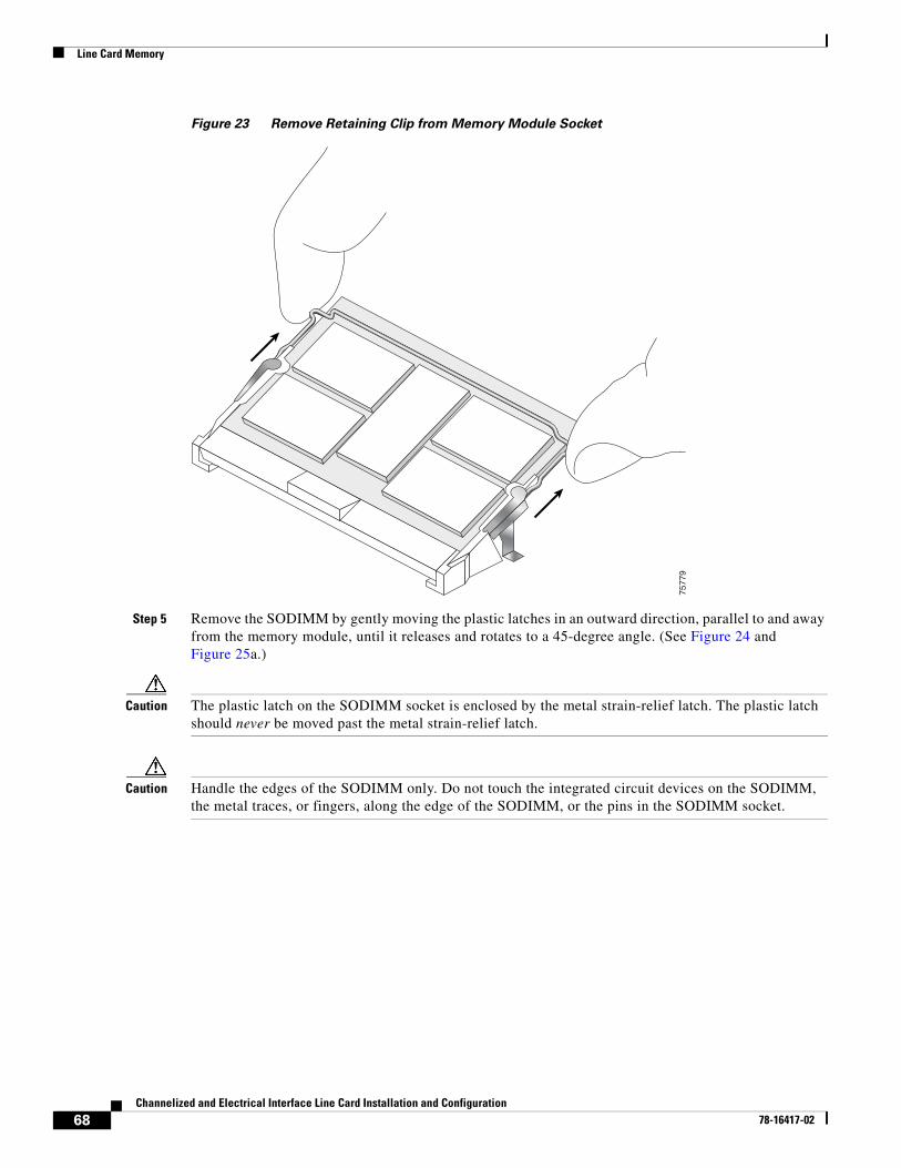
Line Card Memory
Figure 23 Remove Retaining Clip from Memory Module Socket
Step 5 Remove the SODIMM by gently moving the plastic latches in an outward direction, parallel to and away from the memory module, until it releases and rotates to a 45-degree angle. (See Figure 24 and Figure 25a.)
Caution The plastic latch on the SODIMM socket is enclosed by the metal strain-relief latch. The plastic latch should never be moved past the metal strain-relief latch.
Caution Handle the edges of the SODIMM only. Do not touch the integrated circuit devices on the SODIMM, the metal traces, or fingers, along the edge of the SODIMM, or the pins in the SODIMM socket.
7577
9
68Channelized and Electrical Interface Line Card Installation and Configuration
78-16417-02
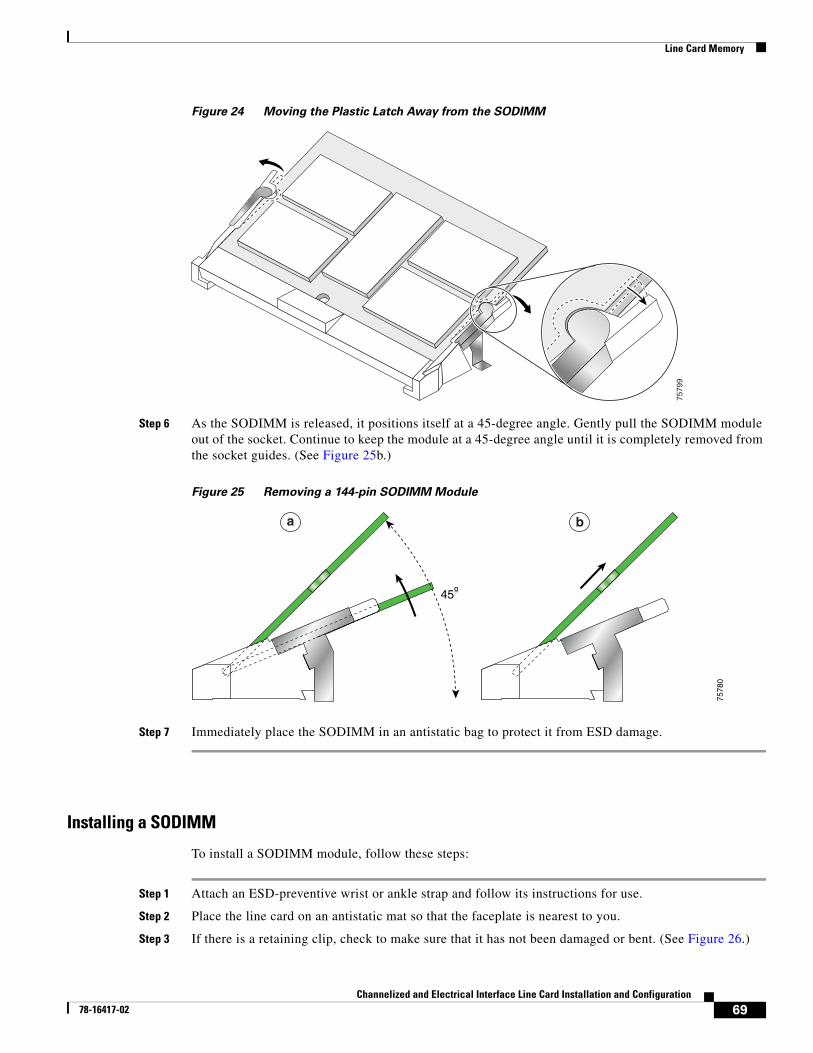
Line Card Memory
Figure 24 Moving the Plastic Latch Away from the SODIMM
Step 6 As the SODIMM is released, it positions itself at a 45-degree angle. Gently pull the SODIMM module out of the socket. Continue to keep the module at a 45-degree angle until it is completely removed from the socket guides. (See Figure 25b.)
Figure 25 Removing a 144-pin SODIMM Module
Step 7 Immediately place the SODIMM in an antistatic bag to protect it from ESD damage.
Installing a SODIMM
To install a SODIMM module, follow these steps:
Step 1 Attach an ESD-preventive wrist or ankle strap and follow its instructions for use.
Step 2 Place the line card on an antistatic mat so that the faceplate is nearest to you.
Step 3 If there is a retaining clip, check to make sure that it has not been damaged or bent. (See Figure 26.)
7579
9
45º
7578
0
a b
69Channelized and Electrical Interface Line Card Installation and Configuration
78-16417-02
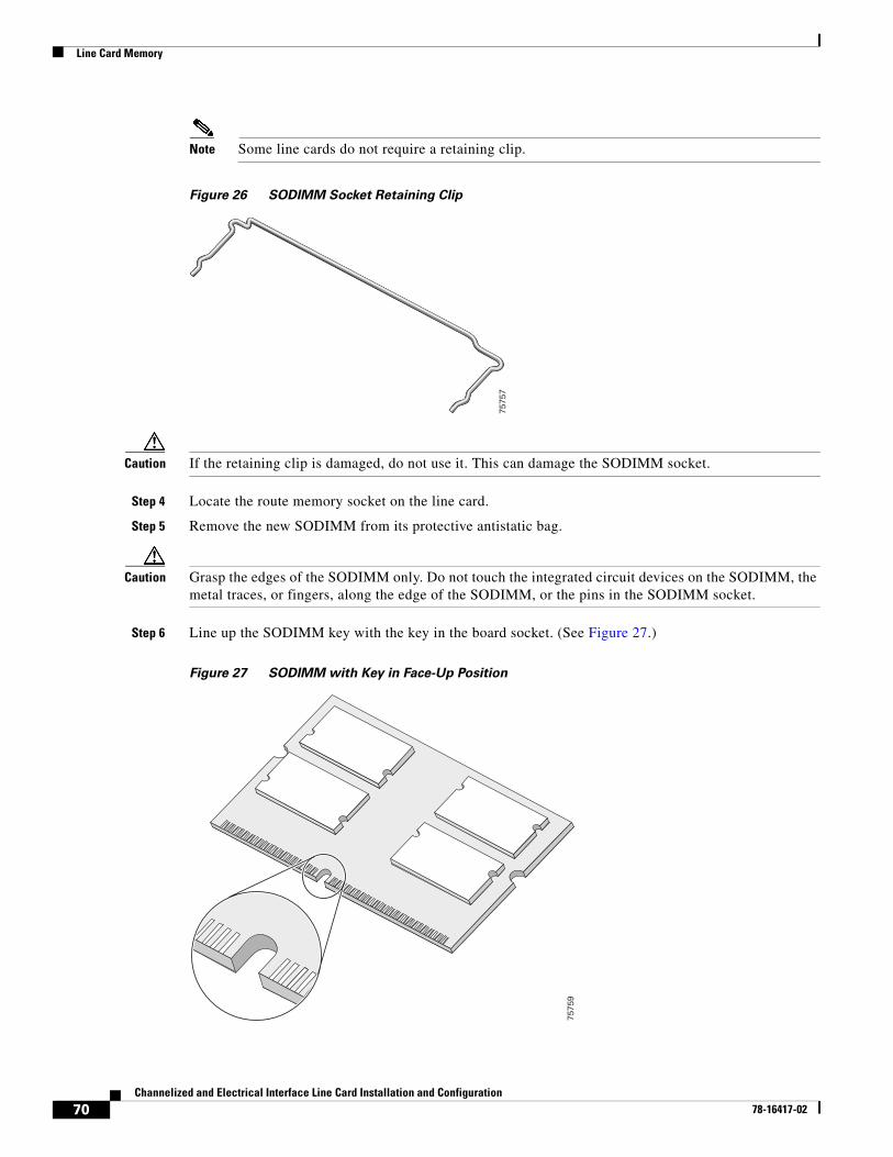
Line Card Memory
Note Some line cards do not require a retaining clip.
Figure 26 SODIMM Socket Retaining Clip
Caution If the retaining clip is damaged, do not use it. This can damage the SODIMM socket.
Step 4 Locate the route memory socket on the line card.
Step 5 Remove the new SODIMM from its protective antistatic bag.
Caution Grasp the edges of the SODIMM only. Do not touch the integrated circuit devices on the SODIMM, the metal traces, or fingers, along the edge of the SODIMM, or the pins in the SODIMM socket.
Step 6 Line up the SODIMM key with the key in the board socket. (See Figure 27.)
Figure 27 SODIMM with Key in Face-Up Position
7575
7
7575
9
70Channelized and Electrical Interface Line Card Installation and Configuration
78-16417-02
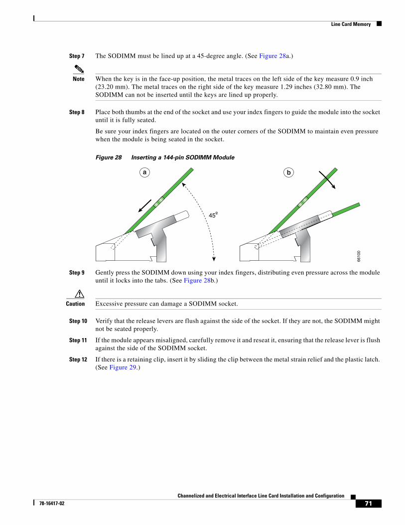
Line Card Memory
Step 7 The SODIMM must be lined up at a 45-degree angle. (See Figure 28a.)
Note When the key is in the face-up position, the metal traces on the left side of the key measure 0.9 inch (23.20 mm). The metal traces on the right side of the key measure 1.29 inches (32.80 mm). The SODIMM can not be inserted until the keys are lined up properly.
Step 8 Place both thumbs at the end of the socket and use your index fingers to guide the module into the socket until it is fully seated.
Be sure your index fingers are located on the outer corners of the SODIMM to maintain even pressure when the module is being seated in the socket.
Figure 28 Inserting a 144-pin SODIMM Module
Step 9 Gently press the SODIMM down using your index fingers, distributing even pressure across the module until it locks into the tabs. (See Figure 28b.)
Caution Excessive pressure can damage a SODIMM socket.
Step 10 Verify that the release levers are flush against the side of the socket. If they are not, the SODIMM might not be seated properly.
Step 11 If the module appears misaligned, carefully remove it and reseat it, ensuring that the release lever is flush against the side of the SODIMM socket.
Step 12 If there is a retaining clip, insert it by sliding the clip between the metal strain relief and the plastic latch. (See Figure 29.)
45º
6610
0
a b
71Channelized and Electrical Interface Line Card Installation and Configuration
78-16417-02
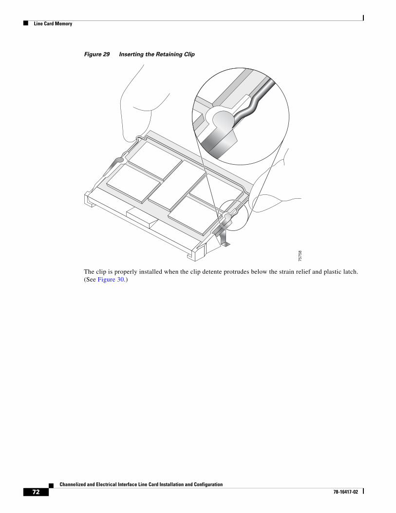
Line Card Memory
Figure 29 Inserting the Retaining Clip
The clip is properly installed when the clip detente protrudes below the strain relief and plastic latch. (See Figure 30.)
7575
8
72Channelized and Electrical Interface Line Card Installation and Configuration
78-16417-02
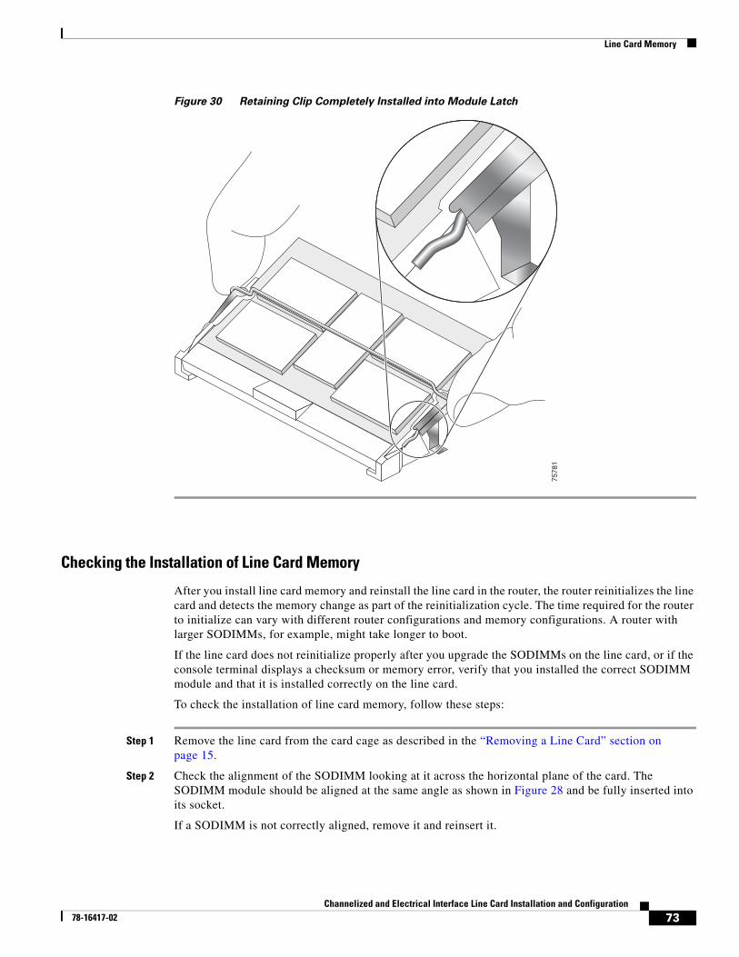
Line Card Memory
Figure 30 Retaining Clip Completely Installed into Module Latch
Checking the Installation of Line Card Memory
After you install line card memory and reinstall the line card in the router, the router reinitializes the line card and detects the memory change as part of the reinitialization cycle. The time required for the router to initialize can vary with different router configurations and memory configurations. A router with larger SODIMMs, for example, might take longer to boot.
If the line card does not reinitialize properly after you upgrade the SODIMMs on the line card, or if the console terminal displays a checksum or memory error, verify that you installed the correct SODIMM module and that it is installed correctly on the line card.
To check the installation of line card memory, follow these steps:
Step 1 Remove the line card from the card cage as described in the “Removing a Line Card” section on page 15.
Step 2 Check the alignment of the SODIMM looking at it across the horizontal plane of the card. The SODIMM module should be aligned at the same angle as shown in Figure 28 and be fully inserted into its socket.
If a SODIMM is not correctly aligned, remove it and reinsert it.
7578
1
73Channelized and Electrical Interface Line Card Installation and Configuration
78-16417-02
Regulatory, Compliance, and Safety Information
Step 3 Reinstall the line card in the card cage as described earlier in this publication and perform another installation check.
If the card fails to restart properly after several attempts and you are unable to resolve the problem, access Cisco.com or contact your Cisco service representative for assistance. Before calling, make note of any console error messages, unusual LED states, or other router indications or behaviors that might help to resolve the problem.
Regulatory, Compliance, and Safety InformationThis section includes regulatory, compliance, and safety information.
Translated Safety Warnings and Agency ApprovalsThe complete list of translated safety warnings and agency approvals is available in the Regulatory Compliance and Safety Information for Cisco 12000 Series Internet Routers publication. (Document Number 78-4347-xx.)
Electromagnetic Compatibility Regulatory Statements
FCC Class A Compliance
This equipment has been tested and found to comply with the limits for a Class A digital device, pursuant to part 15 of the FCC rules. These limits are designed to provide reasonable protection against harmful interference when the equipment is operated in a commercial environment. This equipment generates, uses, and can radiate radio-frequency energy and, if not installed and used in accordance with the instruction manual, may cause harmful interference to radio communications. Operation of this equipment in a residential area is likely to cause harmful interference, in which case users will be required to correct the interference at their own expense.
Modifying the equipment without Cisco’s authorization may result in the equipment no longer complying with FCC requirements for Class A digital devices. In that event, your right to use the equipment may be limited by FCC regulation and you may be required to correct any interference to radio or television communication at your own expense.
You can determine whether your equipment is causing interference by turning it off. If the interference stops, it was probably caused by the Cisco equipment or one of its peripheral devices. If the equipment causes interference to radio or television reception, try to correct the interference by using one or more of the following measures:
• Turn the television or radio antenna until the interference stops.
• Move the equipment to one side or the other of the television or radio.
• Move the equipment farther away from the television or radio.
• Plug the equipment into an outlet that is on a different circuit from the television or radio. (That is, make certain the equipment and the television or radio are on circuits controlled by different circuit breakers or fuses.)
74Channelized and Electrical Interface Line Card Installation and Configuration
78-16417-02
Regulatory, Compliance, and Safety Information
CISPR 22
This apparatus complies with CISPR 22/EN55022 Class B radiated and conducted emissions requirements.
Canada
English Statement of Compliance
This class A digital apparatus complies with Canadian ICES-003.
French Statement of Compliance
Cet appareil numérique de la classe A est conforme à la norme NMB-003 du Canada.
Europe (EU)
This apparatus complies with EN55022 Class B and EN55024 standards when used as ITE/TTE equipment, and EN300386 for Telecommunications Network Equipment (TNE) in both installation environments, telecommunication centers and other indoor locations.
Class A Notice for Hungary
Warning
This equipment is a class A product and should be used and installed properly according to the Hungarian EMC Class A requirements (MSZEN55022). Class A equipment is designed for typical commercial establishments for which special conditions of installation and protection distance are used.
75Channelized and Electrical Interface Line Card Installation and Configuration
78-16417-02
Regulatory, Compliance, and Safety Information
Class A Notice for Taiwan and Other Traditional Chinese Markets
VCCI Compliance for Class B Equipment
Note This notice is applicable to the 1-port channelized OC-12/STM-4 (DS1/E1) ISE line card.
Warning
This is a Class A Information Product, when used in residential environment, it may cause radio frequency interference, under such circumstances, the user may be requested to take appropriate countermeasures. Statement 257
Warning
This is a Class B product based on the standard of the Voluntary Control Council for Interference from Information Technology Equipment (VCCI). If this is used near a radio or television receiver in a domestic environment, it may cause radio interference. Install and use the equipment according to the instruction manual. Statement 157
76Channelized and Electrical Interface Line Card Installation and Configuration
78-16417-02
Regulatory, Compliance, and Safety Information
VCCI Class A Notice for Japan
Class A Notice for Korea
Laser Safetychannelized and electrical interface line cards are equipped with a Class 1 laser, which emits invisible radiation. Do not stare into operational line card ports. The following laser warnings apply to the channelized and electrical interface line card:
• Class 1 Laser Product Warning
• General Laser Warning
Class 1 Laser Product Warning
The following warning applies to single-mode SR, IR, and LR optics:
Warning
This is a Class A product based on the standard of the Voluntary Control Council for Interference by Information Technology Equipment (VCCI). If this equipment is used in a domestic environment, radio disturbance may arise. When such trouble occurs, the user may be required to take corrective actions. Statement 191
Warning
This is a Class A Device and is registered for EMC requirements for industrial use. The seller or buyer should be aware of this. If this type was sold or purchased by mistake, it should be replaced with a residential-use type. Statement 294
77Channelized and Electrical Interface Line Card Installation and Configuration
78-16417-02
Obtaining Documentation
Warning Class 1 laser product.
General Laser Warning
The following warning applies to the channelized and electrical interface line card:
Warning Invisible laser radiation can be emitted from the aperture of the port when no cable is connected. Avoid exposure to laser radiation and do not stare into open apertures.
For translated safety warnings, refer to the Regulatory Compliance and Safety Information for Cisco 12000 Series Internet Routers publication (Document Number 78-4347-xx).
Obtaining DocumentationCisco documentation and additional literature are available on Cisco.com. Cisco also provides several ways to obtain technical assistance and other technical resources. These sections explain how to obtain technical information from Cisco Systems.
Cisco.comYou can access the most current Cisco documentation on the World Wide Web at this URL:
http://www.cisco.com/univercd/home/home.htm
You can access the Cisco website at this URL:
http://www.cisco.com
International Cisco websites can be accessed from this URL:
http://www.cisco.com/public/countries_languages.shtml
Ordering DocumentationYou can find instructions for ordering documentation at this URL:
http://www.cisco.com/univercd/cc/td/doc/es_inpck/pdi.htm
You can order Cisco documentation in these ways:
• Registered Cisco.com users (Cisco direct customers) can order Cisco product documentation from the Networking Products MarketPlace:
http://www.cisco.com/en/US/partner/ordering/index.shtml
• Nonregistered Cisco.com users can order documentation through a local account representative by calling Cisco Systems Corporate Headquarters (California, USA) at 408 526-7208 or, elsewhere in North America, by calling 800 553-NETS (6387).
78Channelized and Electrical Interface Line Card Installation and Configuration
78-16417-02
Documentation Feedback
Documentation FeedbackYou can submit e-mail comments about technical documentation to [email protected].
You can submit comments by using the response card (if present) behind the front cover of your document or by writing to the following address:
Cisco SystemsAttn: Customer Document Ordering170 West Tasman DriveSan Jose, CA 95134-9883
We appreciate your comments.
Obtaining Technical AssistanceFor all customers, partners, resellers, and distributors who hold valid Cisco service contracts, the Cisco Technical Assistance Center (TAC) provides 24-hour-a-day, award-winning technical support services, online and over the phone. Cisco.com features the Cisco TAC website as an online starting point for technical assistance. If you do not hold a valid Cisco service contract, please contact your reseller.
Cisco TAC WebsiteThe Cisco TAC website provides online documents and tools for troubleshooting and resolving technical issues with Cisco products and technologies. The Cisco TAC website is available 24 hours a day, 365 days a year. The Cisco TAC website is located at this URL:
http://www.cisco.com/tac
Accessing all the tools on the Cisco TAC website requires a Cisco.com user ID and password. If you have a valid service contract but do not have a login ID or password, register at this URL:
http://tools.cisco.com/RPF/register/register.do
Opening a TAC CaseUsing the online TAC Case Open Tool is the fastest way to open P3 and P4 cases. (P3 and P4 cases are those in which your network is minimally impaired or for which you require product information.) After you describe your situation, the TAC Case Open Tool automatically recommends resources for an immediate solution. If your issue is not resolved using the recommended resources, your case will be assigned to a Cisco TAC engineer. The online TAC Case Open Tool is located at this URL:
http://www.cisco.com/tac/caseopen
For P1 or P2 cases (P1 and P2 cases are those in which your production network is down or severely degraded) or if you do not have Internet access, contact Cisco TAC by telephone. Cisco TAC engineers are assigned immediately to P1 and P2 cases to help keep your business operations running smoothly.
To open a case by telephone, use one of the following numbers:
Asia-Pacific: +61 2 8446 7411 (Australia: 1 800 805 227) EMEA: +32 2 704 55 55 USA: 1 800 553-2447
79Channelized and Electrical Interface Line Card Installation and Configuration
78-16417-02
Obtaining Additional Publications and Information
For a complete listing of Cisco TAC contacts, go to this URL:
http://www.cisco.com/warp/public/687/Directory/DirTAC.shtml
TAC Case Priority DefinitionsTo ensure that all cases are reported in a standard format, Cisco has established case priority definitions.
Priority 1 (P1)—Your network is “down” or there is a critical impact to your business operations. You and Cisco will commit all necessary resources around the clock to resolve the situation.
Priority 2 (P2)—Operation of an existing network is severely degraded, or significant aspects of your business operation are negatively affected by inadequate performance of Cisco products. You and Cisco will commit full-time resources during normal business hours to resolve the situation.
Priority 3 (P3)—Operational performance of your network is impaired, but most business operations remain functional. You and Cisco will commit resources during normal business hours to restore service to satisfactory levels.
Priority 4 (P4)—You require information or assistance with Cisco product capabilities, installation, or configuration. There is little or no effect on your business operations.
Obtaining Additional Publications and InformationInformation about Cisco products, technologies, and network solutions is available from various online and printed sources.
• Cisco Marketplace provides a variety of Cisco books, reference guides, and logo merchandise. Go to this URL to visit the company store:
http://www.cisco.com/go/marketplace/
• The Cisco Product Catalog describes the networking products offered by Cisco Systems, as well as ordering and customer support services. Access the Cisco Product Catalog at this URL:
http://cisco.com/univercd/cc/td/doc/pcat/
• Cisco Press publishes a wide range of general networking, training and certification titles. Both new and experienced users will benefit from these publications. For current Cisco Press titles and other information, go to Cisco Press online at this URL:
http://www.ciscopress.com
• Packet magazine is the Cisco quarterly publication that provides the latest networking trends, technology breakthroughs, and Cisco products and solutions to help industry professionals get the most from their networking investment. Included are networking deployment and troubleshooting tips, configuration examples, customer case studies, tutorials and training, certification information, and links to numerous in-depth online resources. You can access Packet magazine at this URL:
http://www.cisco.com/packet
• iQ Magazine is the Cisco bimonthly publication that delivers the latest information about Internet business strategies for executives. You can access iQ Magazine at this URL:
http://www.cisco.com/go/iqmagazine
80Channelized and Electrical Interface Line Card Installation and Configuration
78-16417-02
Obtaining Additional Publications and Information
• Internet Protocol Journal is a quarterly journal published by Cisco Systems for engineering professionals involved in designing, developing, and operating public and private internets and intranets. You can access the Internet Protocol Journal at this URL:
http://www.cisco.com/ipj
• Training—Cisco offers world-class networking training. Current offerings in network training are listed at this URL:
http://www.cisco.com/en/US/learning/index.html
This document is to be used in conjunction with the installation and configuration guide for your Cisco 12000 Series Router.
Copyright © 2005 Cisco Systems, Inc. All rights reserved.
CCVP, the Cisco logo, and the Cisco Square Bridge logo are trademarks of Cisco Systems, Inc.; Changing the Way We Work, Live, Play, and Learn is aservice mark of Cisco Systems, Inc.; and Access Registrar, Aironet, BPX, Catalyst, CCDA, CCDP, CCIE, CCIP, CCNA, CCNP, CCSP, Cisco, the CiscoCertified Internetwork Expert logo, Cisco IOS, Cisco Press, Cisco Systems, Cisco Systems Capital, the Cisco Systems logo, Cisco Unity,Enterprise/Solver, EtherChannel, EtherFast, EtherSwitch, Fast Step, Follow Me Browsing, FormShare, GigaDrive, HomeLink, Internet Quotient, IOS,iPhone, IP/TV, iQ Expertise, the iQ logo, iQ Net Readiness Scorecard, iQuick Study, LightStream, Linksys, MeetingPlace, MGX, Networking Academy,Network Registrar, PIX, ProConnect, ScriptShare, SMARTnet, StackWise, The Fastest Way to Increase Your Internet Quotient, and TransPath areregistered trademarks of Cisco Systems, Inc. and/or its affiliates in the United States and certain other countries.
All other trademarks mentioned in this document or Website are the property of their respective owners. The use of the word partner does not imply apartnership relationship between Cisco and any other company. (0709R)
81Channelized and Electrical Interface Line Card Installation and Configuration
78-16417-02

Obtaining Additional Publications and Information
82Channelized and Electrical Interface Line Card Installation and Configuration
78-16417-02