Embed Size (px)
Citation preview

1
2
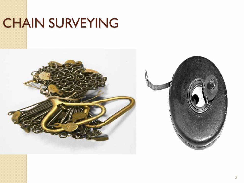
CHAIN SURVEYING
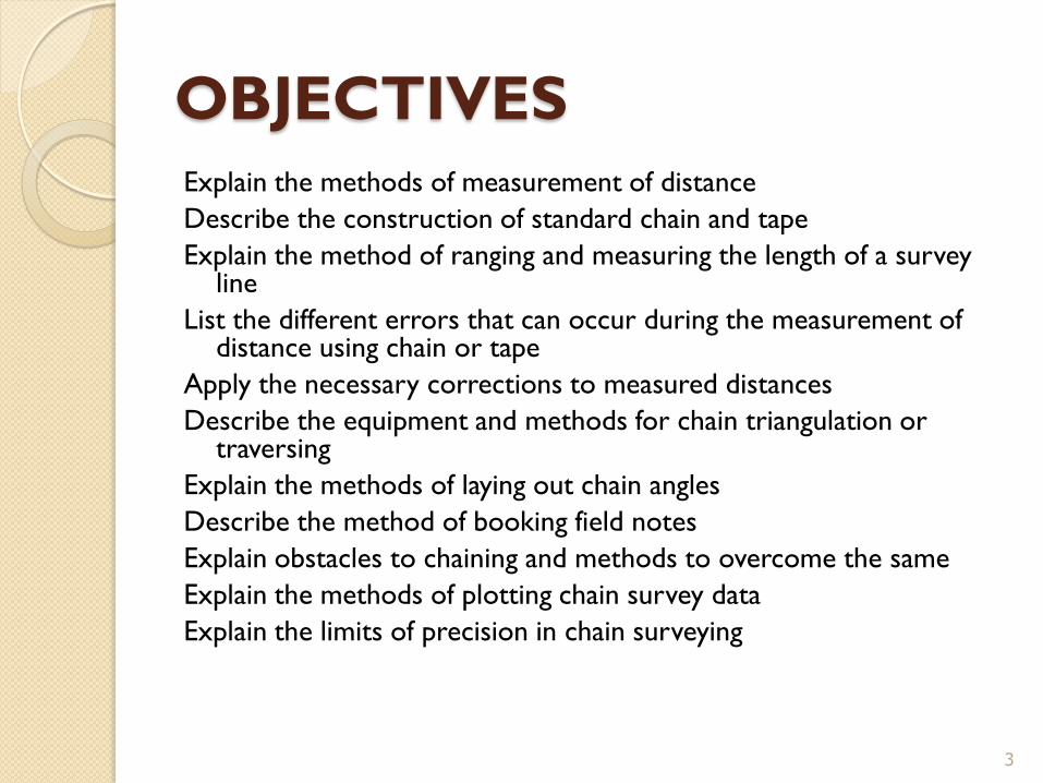
OBJECTIVES
Explain the methods of measurement of distance
Describe the construction of standard chain and tape
Explain the method of ranging and measuring the length of a survey line
List the different errors that can occur during the measurement of distance using chain or tape
Apply the necessary corrections to measured distances
Describe the equipment and methods for chain triangulation or traversing
Explain the methods of laying out chain angles
Describe the method of booking field notes
Explain obstacles to chaining and methods to overcome the same
Explain the methods of plotting chain survey data
Explain the limits of precision in chain surveying
3
THE METRIC CHAIN AND TAPE
ACCESSORIES FOR CHAIN SURVEY
RANGING A LINE
MEASURING ALONG SLOPE
CORRECTIONS TO MEASUREMENTS
CHAIN TRIANGULATION
PROBLEMS IN CHAINING
OBSTACLES TO CHAINING
CHAIN SURVEY
CROSS STAFF SURVEY
4
METRIC CHAIN AND TAPE
Metric chains come in lengths of 5 m, 10 m,
20 m and 30m
Older chains were in 100
feet(engineers),66 feet (Gunter’s) and 33
feet (revenue)
Chains have tallies and rings to identify
intermediate values
5
METRIC CHAINS
BIS standard for chains – is 1492- 1964
Made of 4mm galvanized iron wire
Made of links 200 mm long and connected
by circular or oval rings
End links shorter for providing handles
6

5M AND 10M CHAINS
7
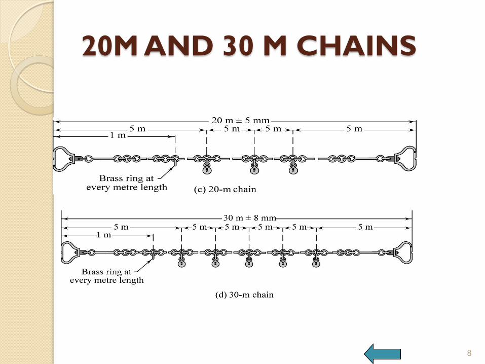
20M AND 30 M CHAINS
8
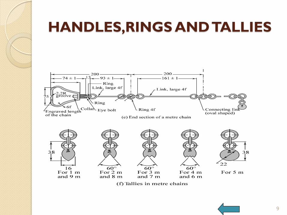
HANDLES,RINGS AND TALLIES
9
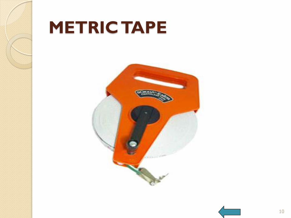
METRIC TAPE
10
TAPES
Cloth tape
Metallic tape
Steel tape
Invar tape
Cloth or linen tapes are not good for field
work as they shrink, tear easily and not
used for survey work.
11
TAPES
12
METALLIC TAPES
Lengths of 2m, 5m, 10 m, 20m, 30m, 50m etc
Yarn interwoven with metal fibres
Metal ring to hold at the outer end
16 mm wide, marked in cm and m
Rolled out by pulling and rolled back using rotating handle
Commonly used for ordinary survey work
13
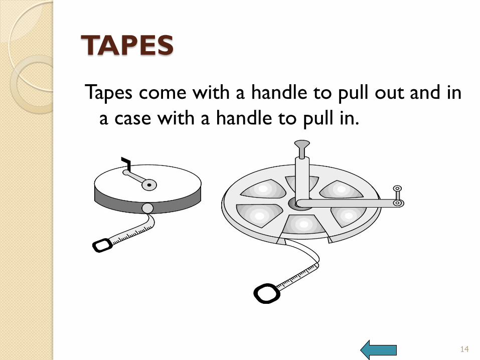
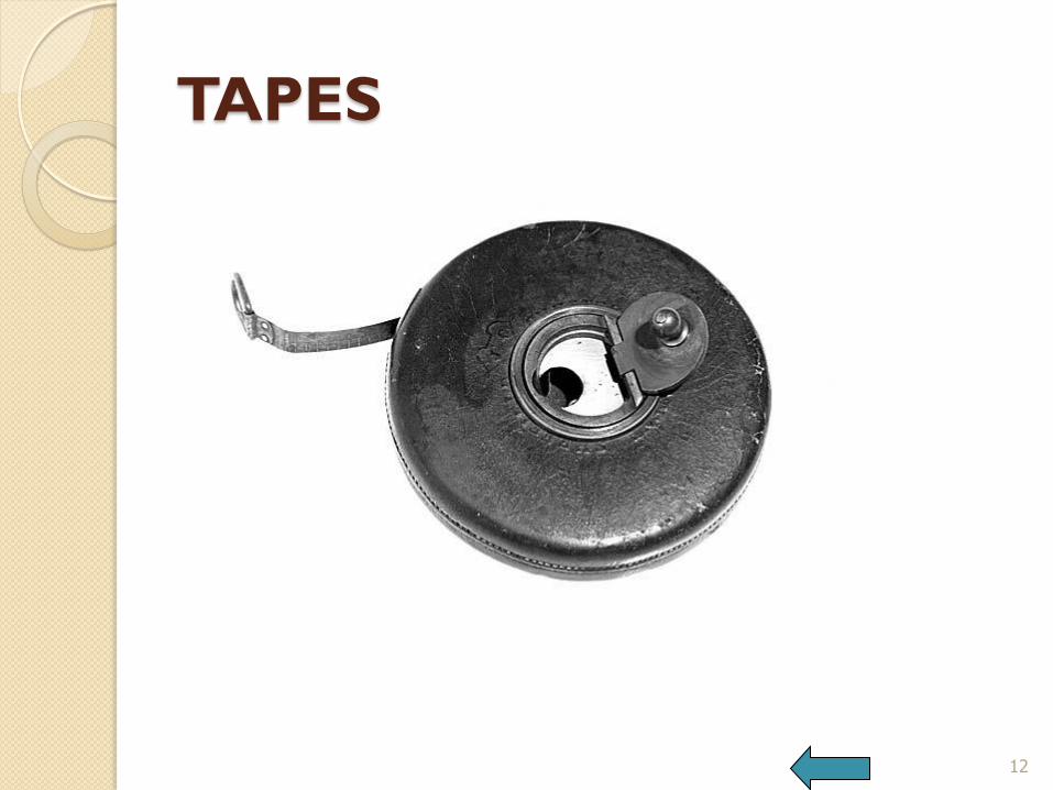
TAPES
Tapes come with a handle to pull out and in
a case with a handle to pull in.
14

STEEL TAPE
Steel tapes are made of galvanized steel or stainless steel
Lengths from 1 m to 50 m Marked in meters, decimeters and
centimeters with end section in millimeters
Costly but very accurate Can be pulled out with the handle and
rolled back automatically Used for accurate survey work
15
INVAR TAPE
Made of an alloy of steel and nickel
About 6 mm wide and in lengths of 30m,
50 m and 100m
Very low thermal coefficient
Used for very precise work as in base line
measurement
Should be handled very carefully
16 BACK
ACCESSORIES
1. Ranging rods
2. Ranging poles
3. Arrows
4. Offset rod
5. Wooden pegs
6. Laths and whites
7. Other equipment for clearing bushes, cleaning
ground
17

18
ACCESSORIES
BACK
RANGING
Ranging required when line is longer than a chain/tape length
Placing a line along the shortest distance between points
When end stations are inter-visible, direct ranging can be done
When end stations not inter-visible, indirect ranging is done
19

DIRECT RANGING
20
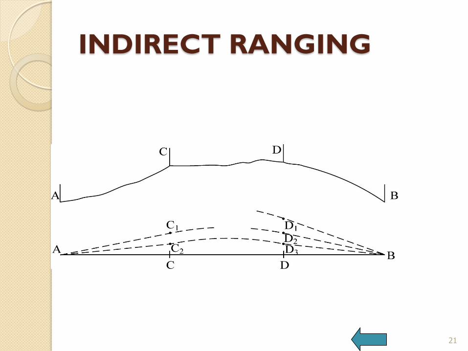
INDIRECT RANGING
21

LINE RANGER
Line ranger is an instrument for ranging
22
BACK
MEASURING ALONG SLOPE
For plotting, horizontal distances are required
For a measured distance along slope, horizontal
distance can be calculated.
Horizontal length is less than length along slope
For a given horizontal distance, slope distance can
be calculated
The increase in length along slope is called
hypotenusal allowance
23
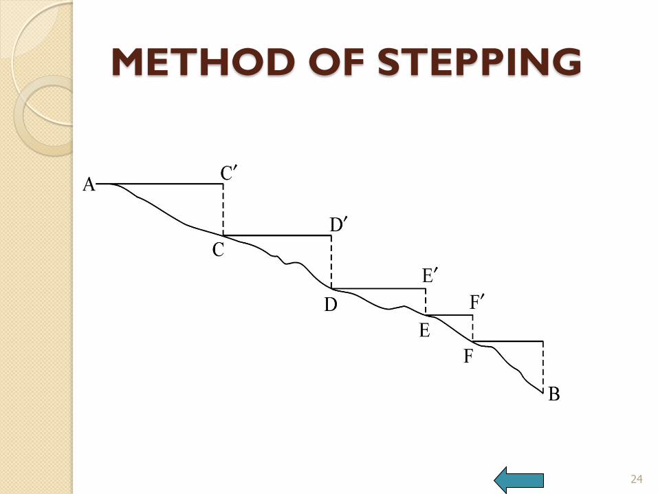
METHOD OF STEPPING
24
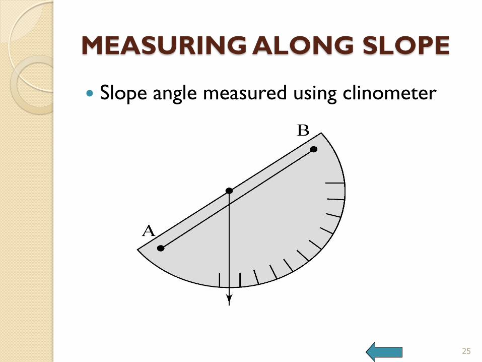
MEASURING ALONG SLOPE
Slope angle measured using clinometer
25

MEASURING ALONG SLOPE
When slope angle is known
26
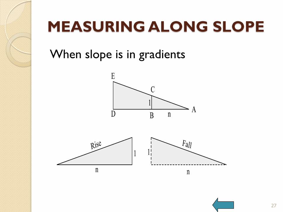
MEASURING ALONG SLOPE
When slope is in gradients
27
HORIZONTAL DISTANCE
Horizontal distance = L COS θ, Where L is
the slope distance and θ is the slope
angle.
If slope is in gradient, 1:n, then
Horizontal distance = L n/[√(1+n²)]
28
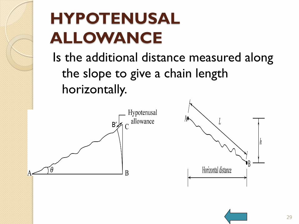
HYPOTENUSAL
ALLOWANCE Is the additional distance measured along
the slope to give a chain length
horizontally.
29
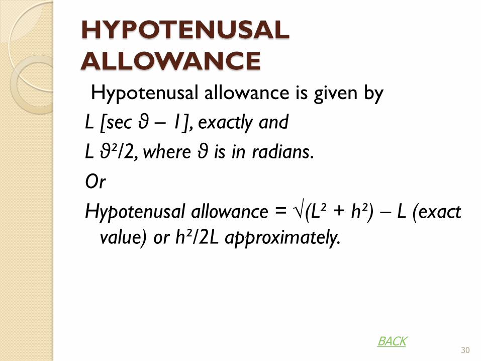
HYPOTENUSAL
ALLOWANCE Hypotenusal allowance is given by
L [sec θ – 1], exactly and
L θ²/2, where θ is in radians.
Or
Hypotenusal allowance = √(L² + h²) – L (exact
value) or h²/2L approximately.
30 BACK
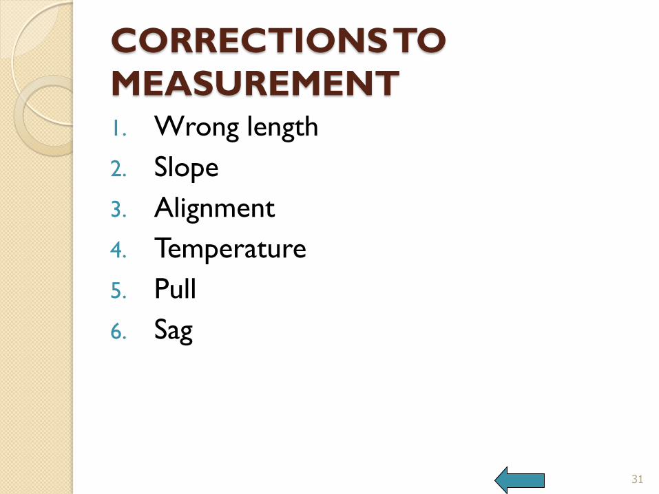
CORRECTIONS TO
MEASUREMENT 1. Wrong length
2. Slope
3. Alignment
4. Temperature
5. Pull
6. Sag
31
INCORRECT LENGTH
32
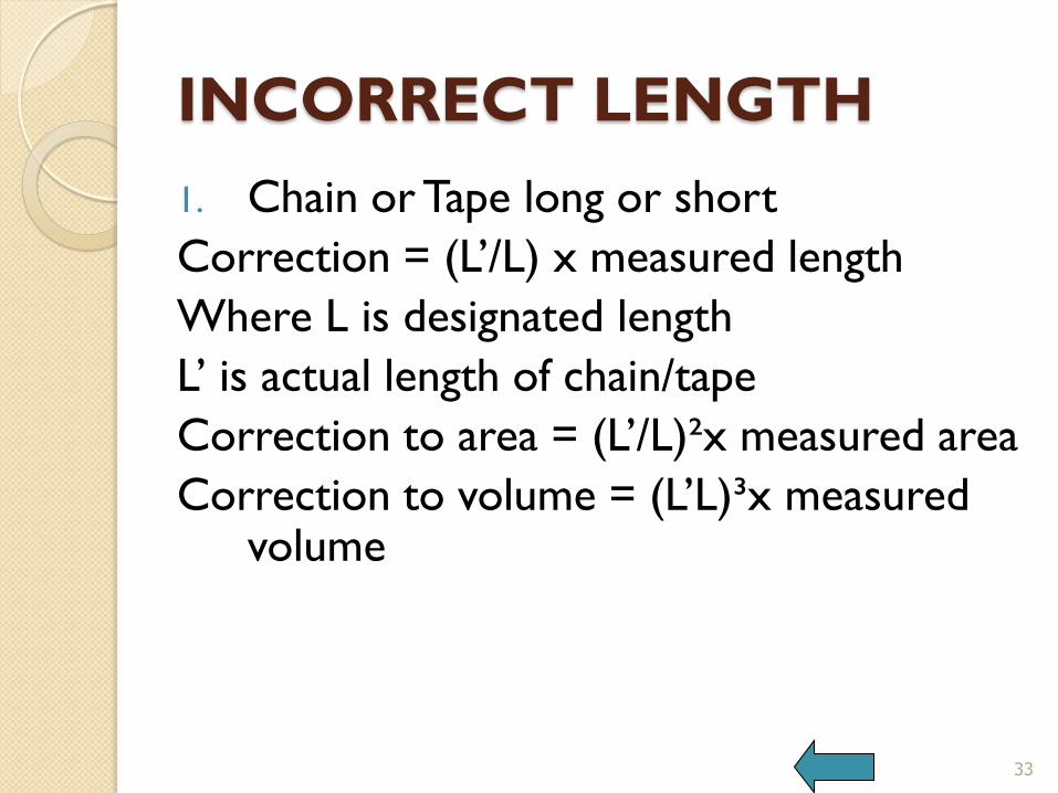
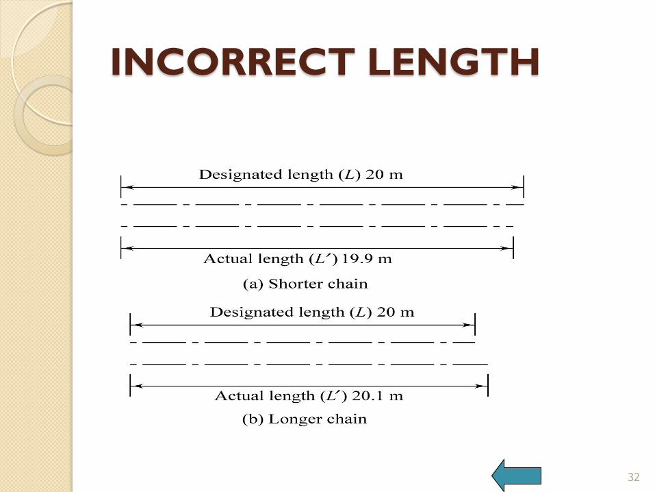
INCORRECT LENGTH
1. Chain or Tape long or short
Correction = (L’/L) x measured length
Where L is designated length
L’ is actual length of chain/tape
Correction to area = (L’/L)²x measured area
Correction to volume = (L’L)³x measured volume
33
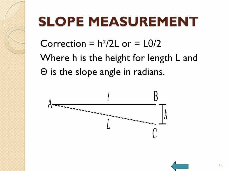
SLOPE MEASUREMENT
Correction = h²/2L or = Lθ/2
Where h is the height for length L and
Θ is the slope angle in radians.
34

INCORRECT ALIGNMENT
Correction = d²/2L
Where d is the deviation over length L
35
TEMPERATURE
Correction = ± Lα t
Where L = Length
α = Coefficient of thermal expansion
(12 x 10^(-6) for steel tape)
t = difference in temperature.
t = (T – T’), T is the ambient temperature and T’ is the standardising temperature.
36

PULL
Correction for pull = ± (P – P’)L/AE
Where P is the pull applied during measurement
P’ is the pull while standardising the tape
L is the length
A is the area of cross section of tape
E is the Young’s modulus of elasticity (200 GN/m²)
37
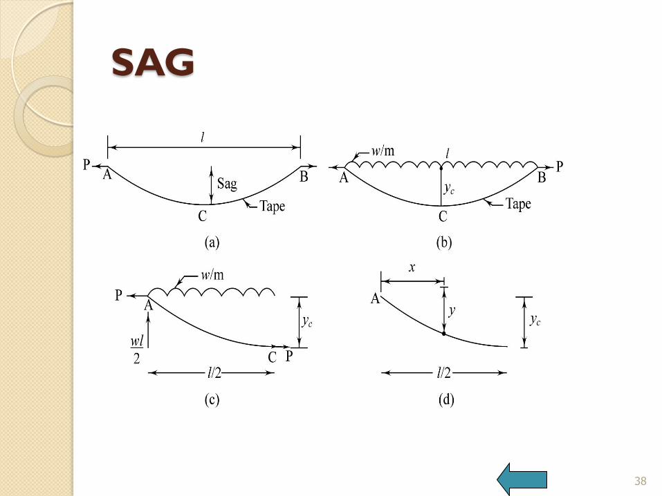
SAG
38
SAG
Correction for sag = Lw²/24n²P²
L is the length
w is the weight per meter
N is the number of spans
P is the pull applied.
39
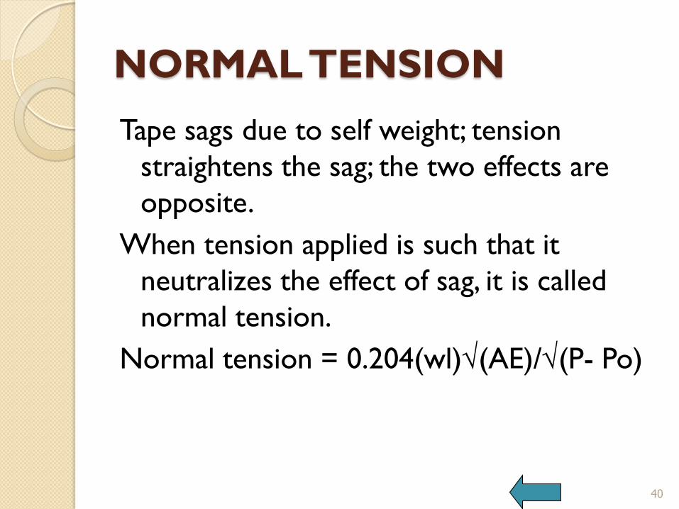
NORMAL TENSION
Tape sags due to self weight; tension
straightens the sag; the two effects are
opposite.
When tension applied is such that it
neutralizes the effect of sag, it is called
normal tension.
Normal tension = 0.204(wl)√(AE)/√(P- Po)
40
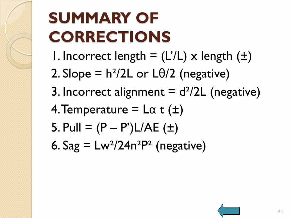
SUMMARY OF
CORRECTIONS 1. Incorrect length = (L’/L) x length (±)
2. Slope = h²/2L or Lθ/2 (negative)
3. Incorrect alignment = d²/2L (negative)
4. Temperature = Lα t (±)
5. Pull = (P – P’)L/AE (±)
6. Sag = Lw²/24n²P² (negative)
41
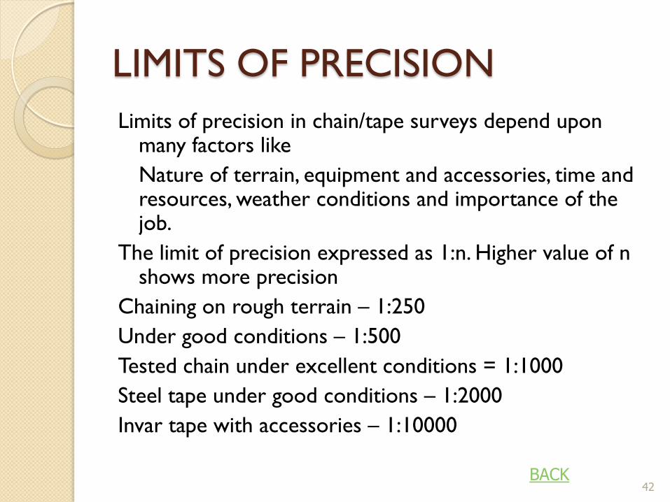
LIMITS OF PRECISION
Limits of precision in chain/tape surveys depend upon many factors like
Nature of terrain, equipment and accessories, time and resources, weather conditions and importance of the job.
The limit of precision expressed as 1:n. Higher value of n shows more precision
Chaining on rough terrain – 1:250
Under good conditions – 1:500
Tested chain under excellent conditions = 1:1000
Steel tape under good conditions – 1:2000
Invar tape with accessories – 1:10000
42 BACK
Problem 1
P and Q are the two points 517m apart on
the same bank of a river. The bearings of a
tree on the other bank observed from P
and Q are N 33 ̊ 40’ E and N 43 ̊ 20’ W. Find the width of the river if the bearings of PQ are N 78 ̊ 0’ E.
43

Problem 2
A survey line BAC crosses a river. A and C
being on the near and distant banks
respectively. Standing at D, a point 50
metres measured perpendicular to AB
from A, the bearings of C and B are 320 ̊ and 230 ̊ respectively. AB being 25 m, find the width of the river.
44
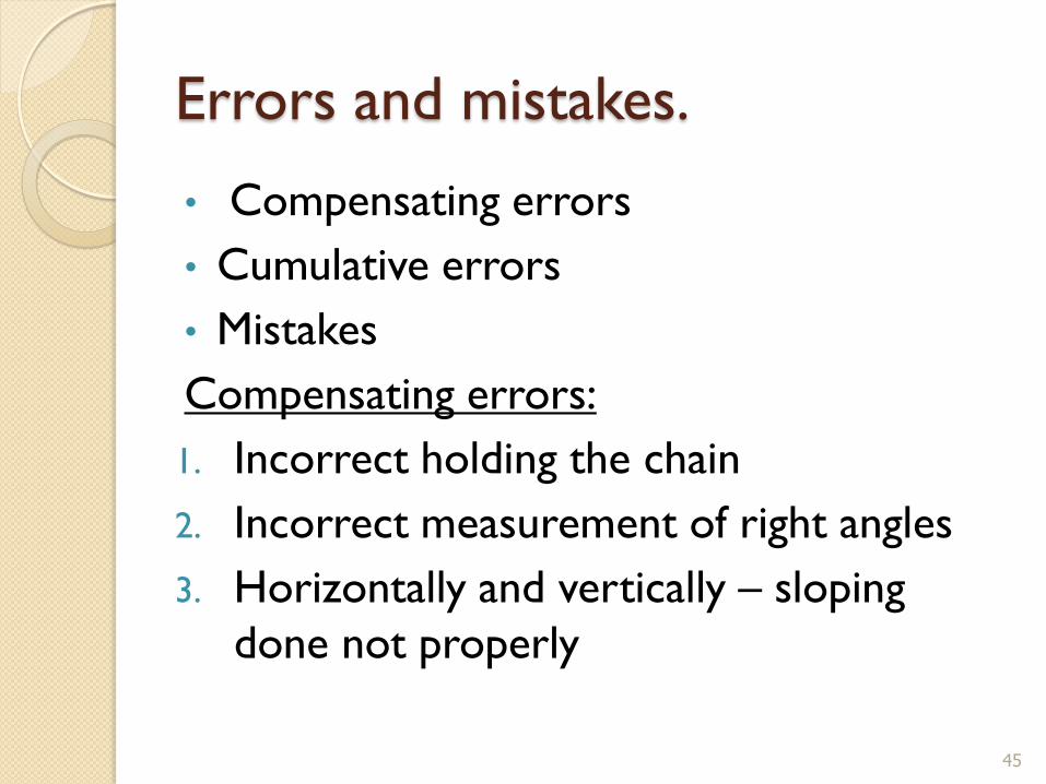
Errors and mistakes.
• Compensating errors
• Cumulative errors
• Mistakes
Compensating errors:
1. Incorrect holding the chain
2. Incorrect measurement of right angles
3. Horizontally and vertically – sloping
done not properly
45

Contd..
Cumulative errors:
Positive errors
Negative errors
Mistakes:
46
CHAIN TRIANGULATION
47
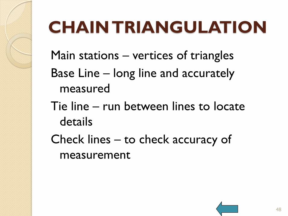
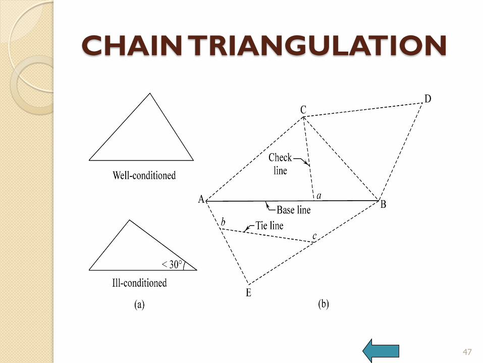
CHAIN TRIANGULATION
Main stations – vertices of triangles
Base Line – long line and accurately
measured
Tie line – run between lines to locate
details
Check lines – to check accuracy of
measurement
48
OFFSETS
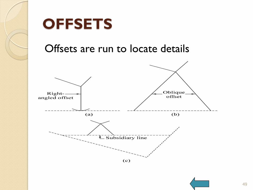
Offsets are run to locate details
49

OFFSETS
1. Offsets generally at right angles to chain
line
2. Oblique offsets are also taken
3. Number of offsets depend upon the
detail.
4. Very long offsets are avoided.
50
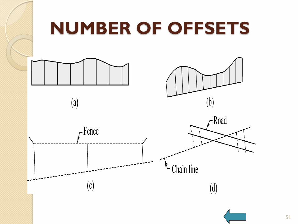
NUMBER OF OFFSETS
51
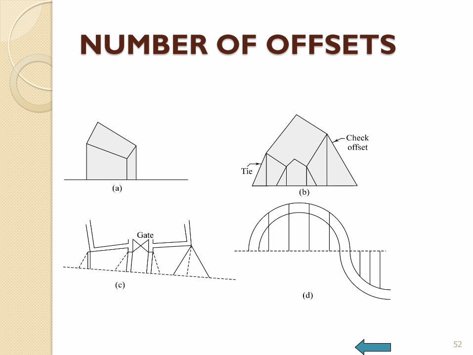
NUMBER OF OFFSETS
52

INSTRUMENTS FOR
SETTING RIGHT ANGLES For taking right-angled offsets, instruments
used are cross staff, optical square, prism
square.
53
Chain line
offset
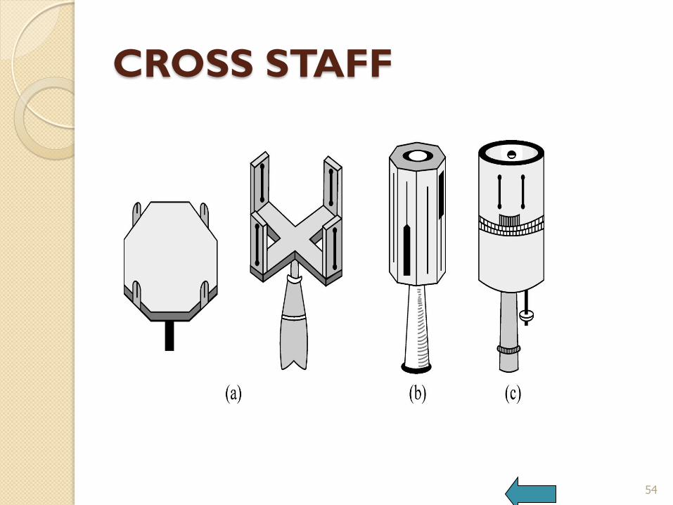
CROSS STAFF
54
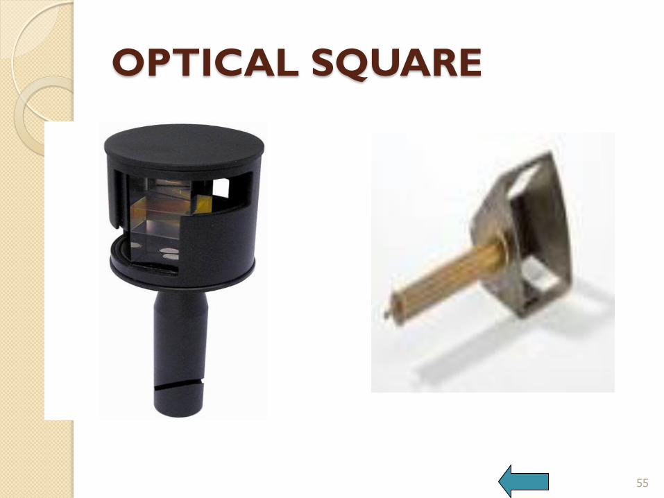
OPTICAL SQUARE
55

OPTICAL SQUARE
56

OPTICAL SQUARE
57
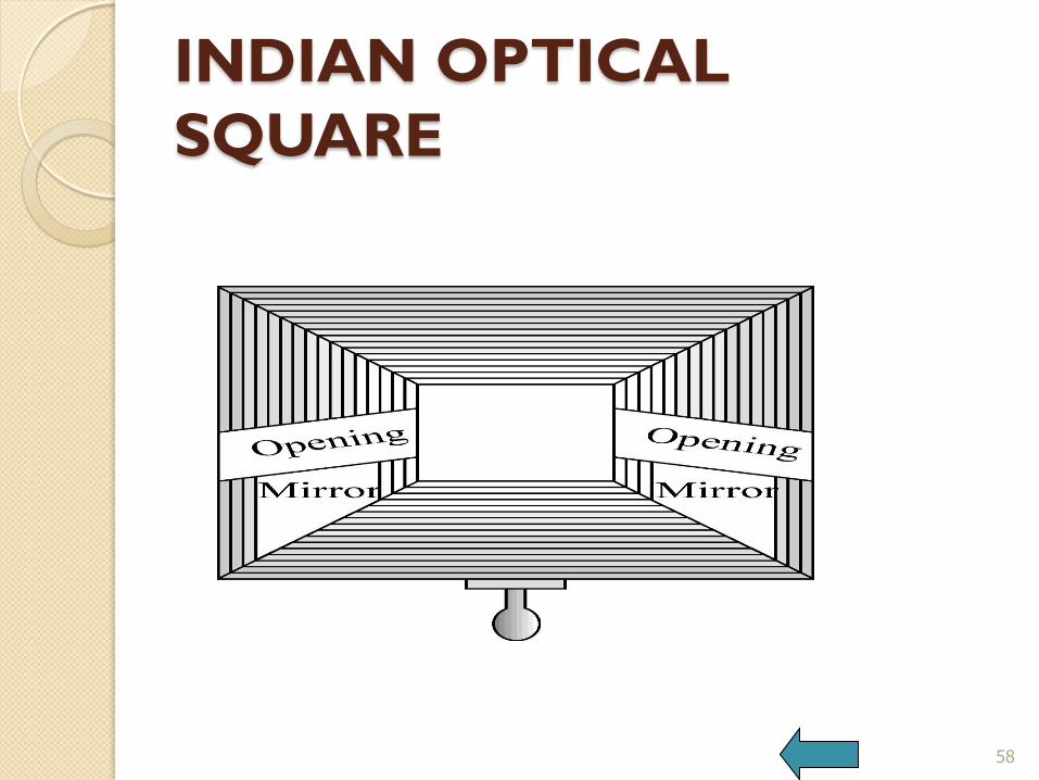
INDIAN OPTICAL
SQUARE
58
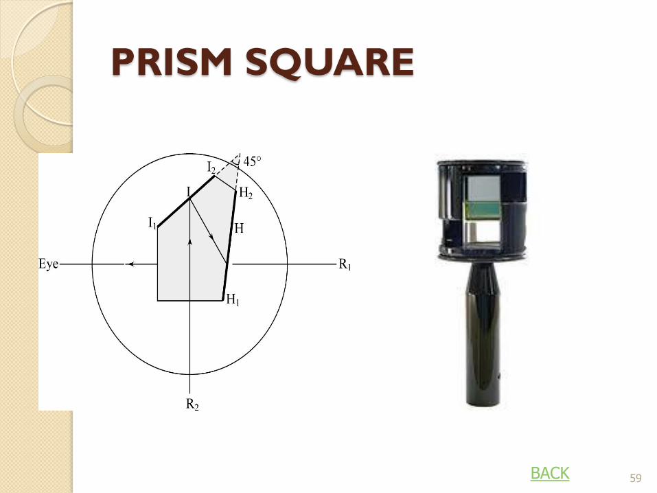
PRISM SQUARE
59 BACK

OBSTACLES TO CHAINING
Chaining not possible, No intervisibility
60
OBSTACLES TO CHAINING
61
OBSTACLES TO CHAINING
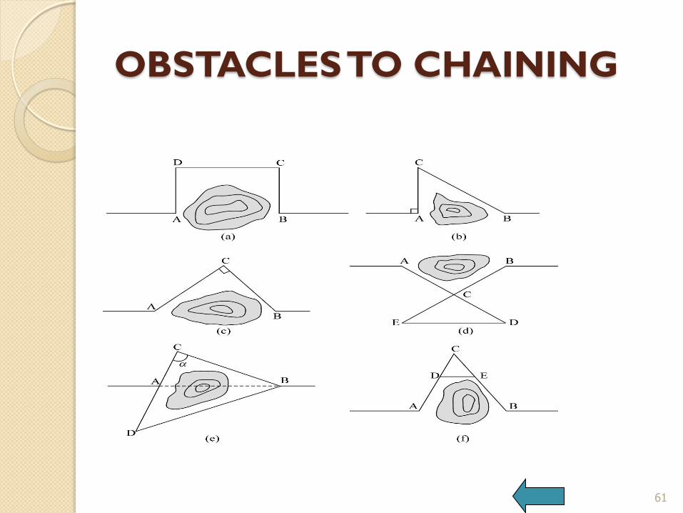
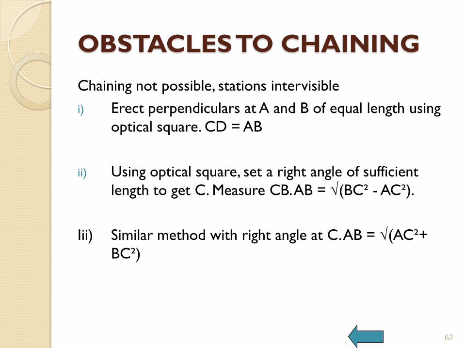
Chaining not possible, stations intervisible
i) Erect perpendiculars at A and B of equal length using
optical square. CD = AB
ii) Using optical square, set a right angle of sufficient
length to get C. Measure CB. AB = √(BC² - AC²).
Iii) Similar method with right angle at C. AB = √(AC²+
BC²)
62

OBSTACLES TO CHAINING
iv) Select point C such that A and B are visible. Range AC
and make CD = AC. Range BC and make CE = BC.
Measured ED which is equal to AB.
v) When it is not possible to set a right angle, select
point C. Range CA and make AD = CA.
Cosα = (BC² +CD² -BD²)/(2BCxCD)
AB² = BC² + CA² + 2 CA x BC x cos α.
vi) Select a point C approximately midway of AB and
such that A and B are visible. Measure CA and CB.
CD and CE are made proportional to CA and CB.
Measure DE and calculate AB from similar triangles.
63
OBSTACLES TO CHAINING
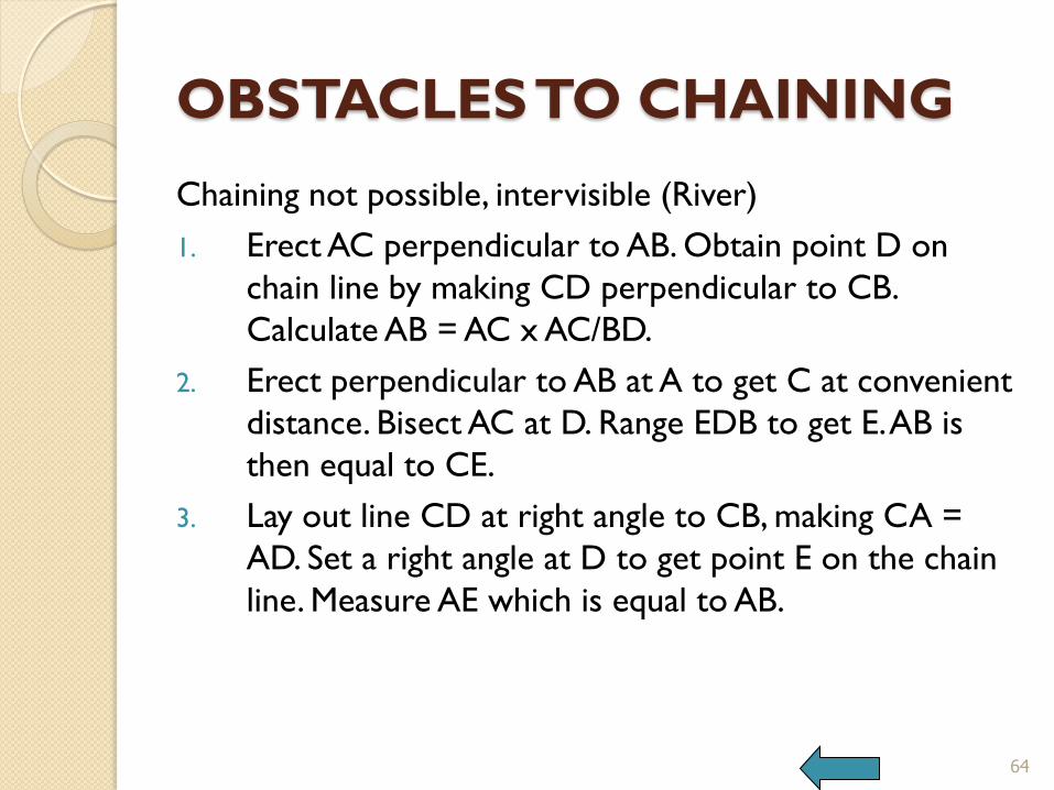
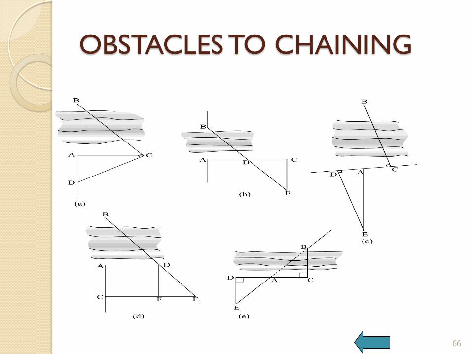
Chaining not possible, intervisible (River)
1. Erect AC perpendicular to AB. Obtain point D on
chain line by making CD perpendicular to CB.
Calculate AB = AC x AC/BD.
2. Erect perpendicular to AB at A to get C at convenient
distance. Bisect AC at D. Range EDB to get E. AB is
then equal to CE.
3. Lay out line CD at right angle to CB, making CA =
AD. Set a right angle at D to get point E on the chain
line. Measure AE which is equal to AB.
64

OBSTACLES TO CHAINING
4. Select a convenient distance CA. Erect perpendiculars at
A and C and make AC = DF. Extend the line CE to
obtain E in line with DB. AB = AC x DF/ FE.
5. When the chain line crosses the river obliquely, make a
line DAC such that CB and DE are perpendicular to this
line. Point E is so chosen that EAB is in line. AE = AB
65
OBSTACLES TO CHAINING
66
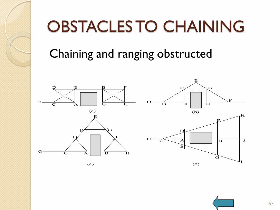
OBSTACLES TO CHAINING
Chaining and ranging obstructed
67
OBSTACLES TO CHAINING
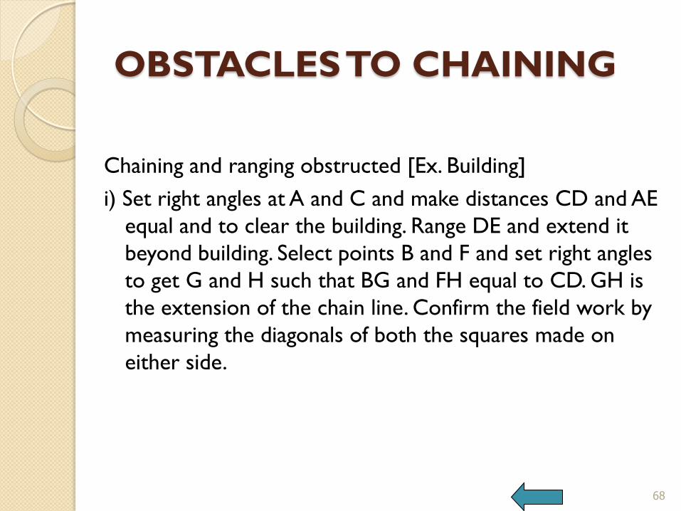
Chaining and ranging obstructed [Ex. Building]
i) Set right angles at A and C and make distances CD and AE
equal and to clear the building. Range DE and extend it
beyond building. Select points B and F and set right angles
to get G and H such that BG and FH equal to CD. GH is
the extension of the chain line. Confirm the field work by
measuring the diagonals of both the squares made on
either side.
68
OBSTACLES TO CHAINING
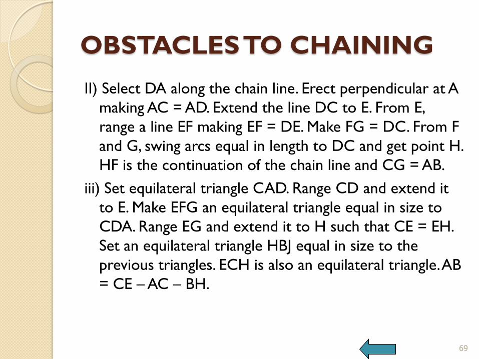
II) Select DA along the chain line. Erect perpendicular at A
making AC = AD. Extend the line DC to E. From E,
range a line EF making EF = DE. Make FG = DC. From F
and G, swing arcs equal in length to DC and get point H.
HF is the continuation of the chain line and CG = AB.
iii) Set equilateral triangle CAD. Range CD and extend it
to E. Make EFG an equilateral triangle equal in size to
CDA. Range EG and extend it to H such that CE = EH.
Set an equilateral triangle HBJ equal in size to the
previous triangles. ECH is also an equilateral triangle. AB
= CE – AC – BH.
69
OBSTACLES TO CHAINING
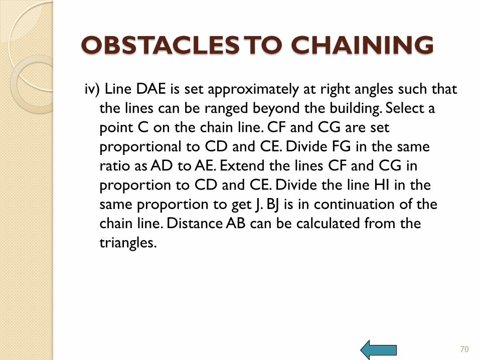
iv) Line DAE is set approximately at right angles such that
the lines can be ranged beyond the building. Select a
point C on the chain line. CF and CG are set
proportional to CD and CE. Divide FG in the same
ratio as AD to AE. Extend the lines CF and CG in
proportion to CD and CE. Divide the line HI in the
same proportion to get J. BJ is in continuation of the
chain line. Distance AB can be calculated from the
triangles.
70

OBSTACLES TO CHAINING
Distance between points past an obstacle
To find AB, Take a convenient point C and measure CA and CB.
Select point D on CA and find E as a proportional distance of CD x CB/CA.
Measure DE. AB can be found as DE x CD/CA.
71 BACK

CHAIN SURVEY
PROCEDURE
1. Reconnaissance
2. Equipment – chain/tape, arrows, ranging rods, ranging poles, offset rod, pegs etc
3. Marking stations
4. Triangulation
5. Locating details
72
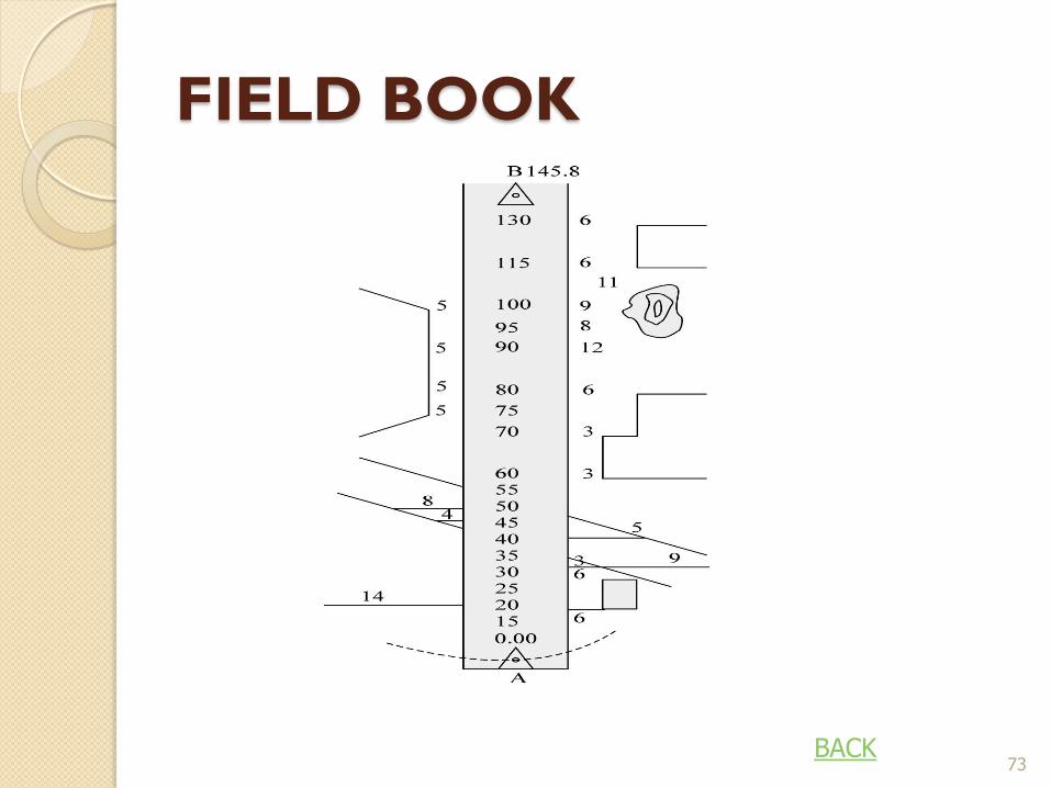
FIELD BOOK
73 BACK
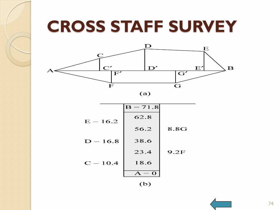
CROSS STAFF SURVEY
74

CROSS STAFF SURVEY
BOOKING READINGS The reading of cross staff survey are booked by chainages along
the central line and marking the offsets to points on the left and right sides.
The distances to the points are noted along with the point name.
75
END


![Hash Table [Chaining]](https://img.pdfslide.us/doc/110x75/55cf91c6550346f57b908924/hash-table-chaining.jpg)