Embed Size (px)
Citation preview
Ch. 3: Equilibrium
3.0 Outline 123 Mechanical System Isolation (FBD) 1252-D Systems Equilibrium Conditions 1443-D Systems Equilibrium Conditions 174
3.0 Outline
123
Ch. 3: Equilibrium
3.0 Outline
When a body is in equilibrium, the resultant on the body is zero.And if the resultant on a body is zero, the body is in equilibrium.
So,
is the necessary and sufficient conditions for equilibrium.
3.0 Outline
∑ ∑F = 0 M = 0
124
Ch. 3: Equilibrium
3.1 Mechanical System Isolation (FBD)
Free-Body Diagram (FBD) is the most important first step in the mechanics problems. It defines clearly the interested system to be analyzed. It represents all forces which act on the system. The system may be rigid, nonrigid, or their combinations. The system may be in fluid, gaseous, solid, or their combinations.
FBD represents the isolated / combination of bodies as a single body. Corresponding indicated forces may be
1. Contact force with other bodies that are removed virtually.
2. Body force such as gravitational or magnetic attraction forces.
3.1 FBD
125
Ch. 3: Equilibrium
3.1 FBD
126
Ch. 3: Equilibrium
3.1 FBD
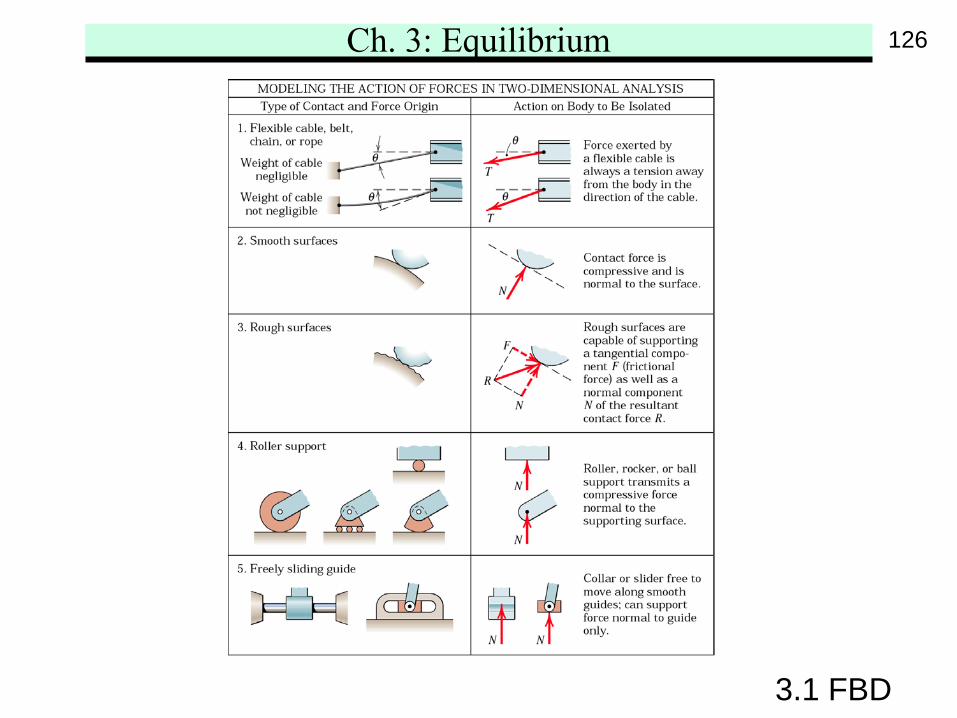
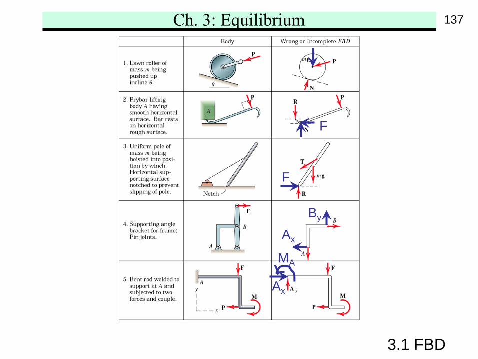
Remarks1. Force by flexible cable is always a tension. Weight
of the cable may be significant.2. Smooth surface ideally cannot support the tangential
or frictional force. Contact force of the rough surfacemay not necessarily be normal to the tangential surface.
3. Roller, rocker, smooth guide, or slider ideallyeliminate the frictional force. That is the supportscannot provide the resistance to motionin the tangential direction.
4. Pin connection provides support force in any directionnormal to the pin axis. If the joint is not free to turn,a resisting couple may also be supported.
127
Ch. 3: Equilibrium
3.1 FBD
128
Ch. 3: Equilibrium
3.1 FBD
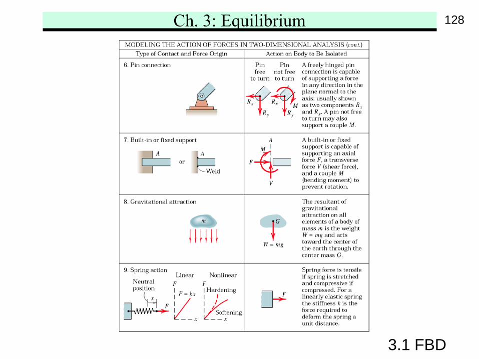
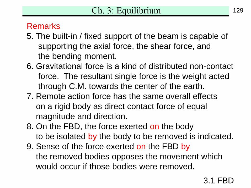
Remarks5. The built-in / fixed support of the beam is capable of
supporting the axial force, the shear force, andthe bending moment.
6. Gravitational force is a kind of distributed non-contactforce. The resultant single force is the weight actedthrough C.M. towards the center of the earth.
7. Remote action force has the same overall effectson a rigid body as direct contact force of equalmagnitude and direction.
8. On the FBD, the force exerted on the bodyto be isolated by the body to be removed is indicated.
9. Sense of the force exerted on the FBD bythe removed bodies opposes the movement whichwould occur if those bodies were removed.
129
Ch. 3: Equilibrium
3.1 FBD
Remarks10. If the correct sense cannot be known at first place,
the sense of the scalar component is arbitrarilyassigned. Upon computation, a negative algebraicsign indicates that the correct sense is oppositeto that assigned.
130
Ch. 3: Equilibrium
3.1 FBD
Construction of FBD1. Make decision which body or system is to be isolated.
That system will usually involve the unknown quantities.2. Draw complete external boundary of the system
to completely isolate it from all other contactingor attracting bodies.
3. All forces that act on the isolated body by the removedcontacting and attracting bodies are representedon the isolated body diagram. Forces should beindicated by vector arrows, each with its magnitude,direction, and sense. Consistency of the unknownsmust be carried throughout the calculation.
4. Assign the convenient coordinate axes.Only after the FBD is completed should the governingequations be applied.
131
Ch. 3: Equilibrium
3.1 FBD
132
Ch. 3: Equilibrium
3.1 FBD
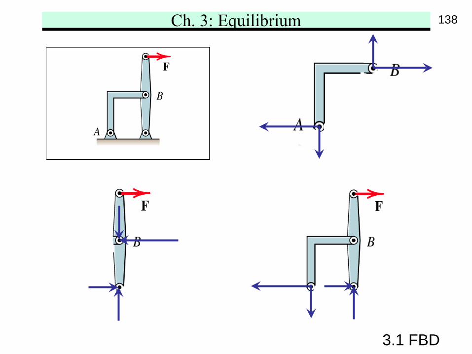
Note1. Include as much as possible the system in FBD
while the unknowns are still being revealed.2. Internal forces to a rigid assembly of members do not
influence the values of the external reactions. And sothe external response of the mechanism as a wholewould be unchanged.
3. Include the weights of the members on FBD.4. Try to get the correct sense of unknown vectors by
visualizing the motion of the whole system whenthe supports are pretended to disappear. The correctsense will oppose the motion’s direction.
5. Follow the action of force prototypes in determiningthe forces acted by the removed bodies.
133
Ch. 3: Equilibrium
3.1 FBD
134
Ch. 3: Equilibrium
3.1 FBD
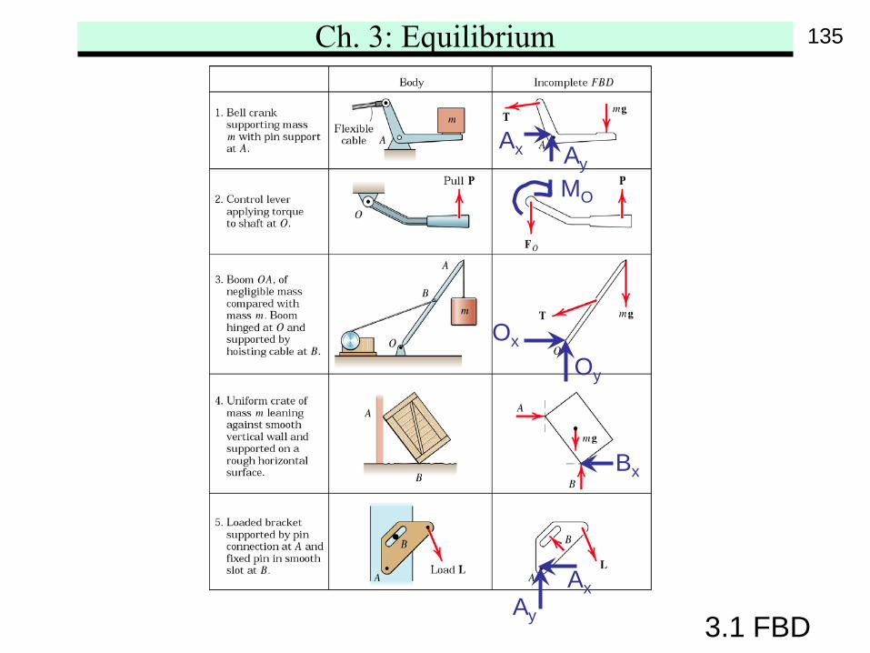
Ax Ay
MO
AxAy
Oy
Ox
Bx
135
Ch. 3: Equilibrium
3.1 FBD
136
Ch. 3: Equilibrium
3.1 FBD
Ax
MA
F
F
By
Ax
137
Ch. 3: Equilibrium
3.1 FBD
138
Ch. 3: Equilibrium
3.1 FBD
139
Ch. 3: Equilibrium
3.1 FBD
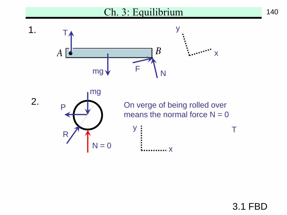
1. T
mg
x
NF
y
P
T
2.mg
R
On verge of being rolled overmeans the normal force N = 0
N = 0
y
x
140
Ch. 3: Equilibrium
3.1 FBD
y
x
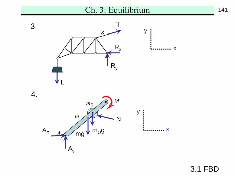
3.
L
T
Rx
Ry
4.
y
xmg mOg
N
Ay
AX
141
Ch. 3: Equilibrium
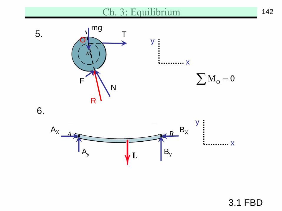
OM 0=∑
3.1 FBD
5.
FN
R
mgT
y
x
O
6.y
xAy
AX
By
BX
142
Ch. 3: Equilibrium
3.1 FBD
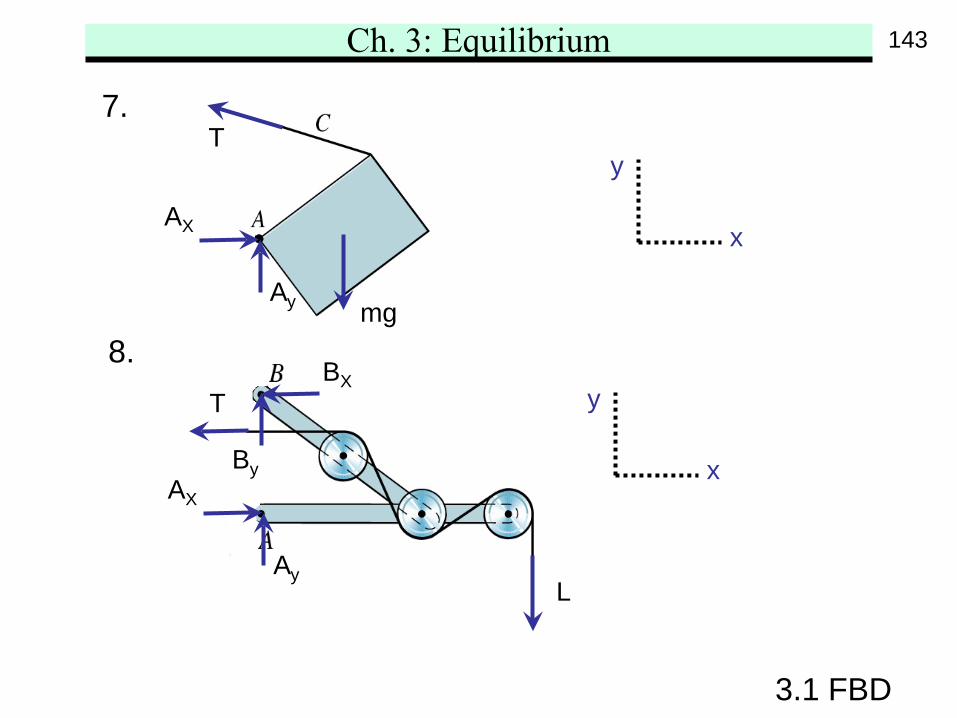
7.
y
x
8.mg
T
Ay
AX
y
x
L
T
Ay
AX
By
BX
143
Ch. 3: Equilibrium
3.2 2-D Eqilibrium Conditions
3.2 2-D Equilibrium Conditions
A body is in equilibrium if all forces and momentsapplied to it are in balance. In scalar form,
x y OF 0 F 0 M 0= = =∑ ∑ ∑• The x-y coordinate system and the moment point Ocan be chosen arbitrarily.• Complete equilibrium in 2-D motion must satisfy allthree equations. However, they are independentto each other. That is, equilibrium may only be satisfiedin some generalized coordinates.• System in equilibrium may stay still or move withconstant velocity. In both cases, the acceleration is zero.
144
Ch. 3: Equilibrium
3.2 2-D Eqilibrium Conditions
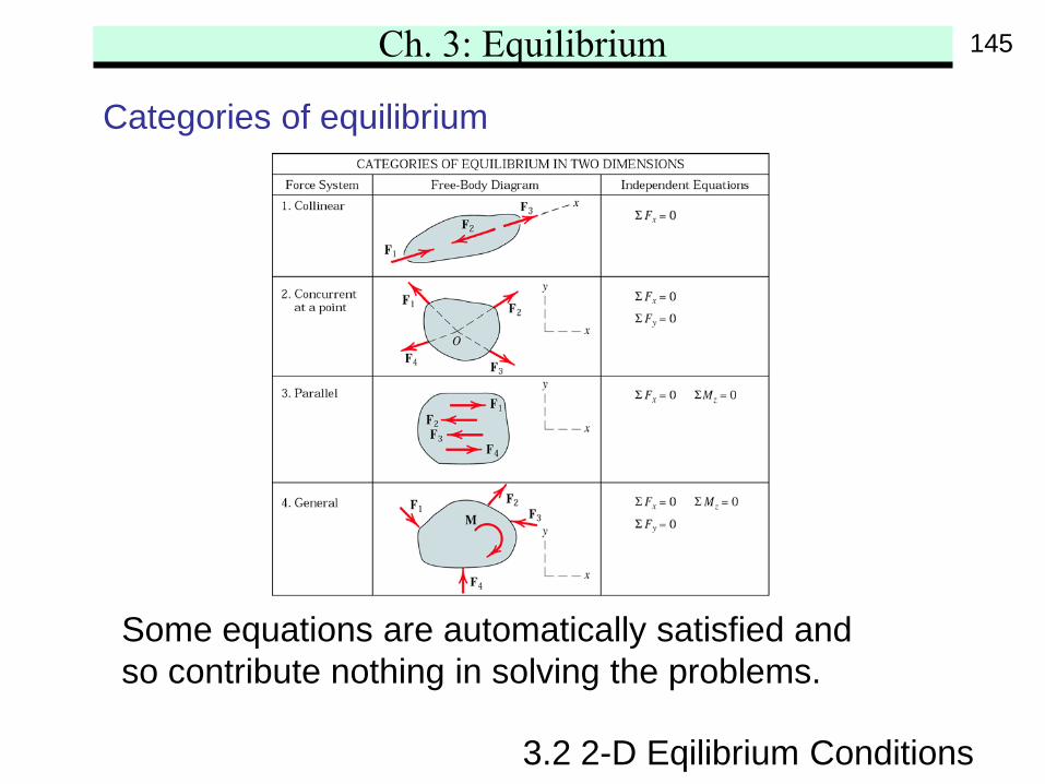
Categories of equilibrium
Some equations are automatically satisfied andso contribute nothing in solving the problems.
145
Ch. 3: Equilibrium
3.2 2-D Eqilibrium Conditions
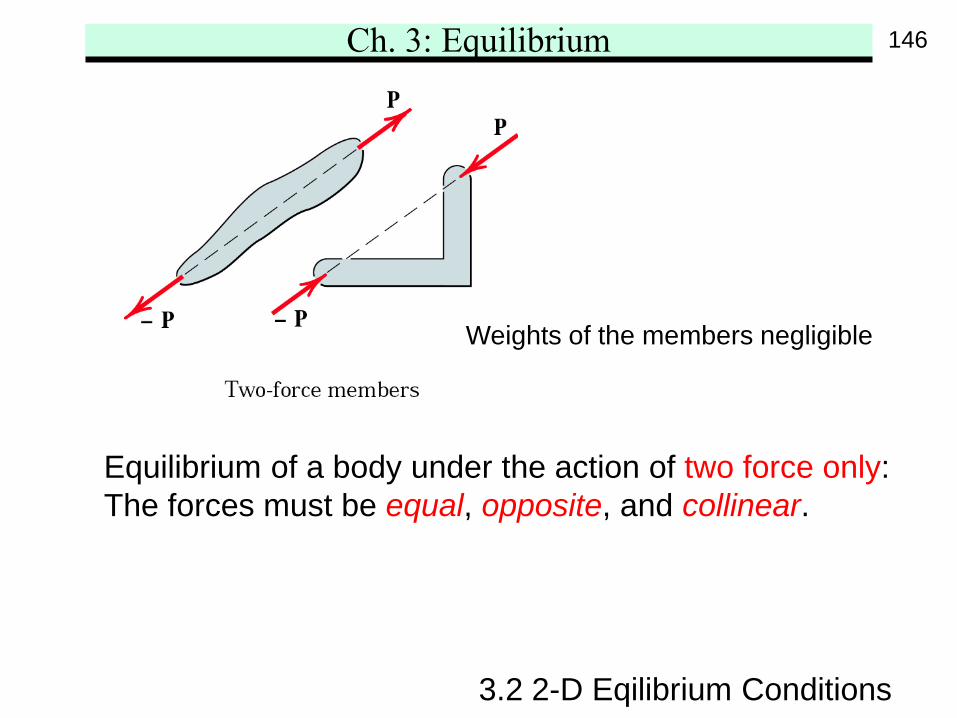
Equilibrium of a body under the action of two force only:The forces must be equal, opposite, and collinear.
Weights of the members negligible
146
Ch. 3: Equilibrium
3.2 2-D Eqilibrium Conditions
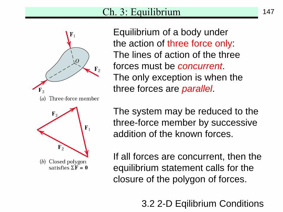
Equilibrium of a body underthe action of three force only:The lines of action of the three forces must be concurrent.The only exception is when the three forces are parallel.
The system may be reduced to the three-force member by successive addition of the known forces.
If all forces are concurrent, then the equilibrium statement calls for the closure of the polygon of forces.
147
Ch. 3: Equilibrium
3.2 2-D Eqilibrium Conditions
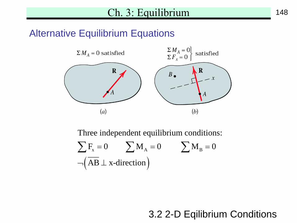
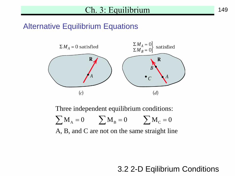
Alternative Equilibrium Equations
( )x A B
Three independent equilibrium conditions:F 0 M 0 M 0
AB x-direction
= = =
¬ ⊥
∑ ∑ ∑
148
Ch. 3: Equilibrium
A B C
Three independent equilibrium conditions:M 0 M 0 M 0
A, B, and C are not on the same straight line= = =∑ ∑ ∑
3.2 2-D Eqilibrium Conditions
Alternative Equilibrium Equations
149
Ch. 3: Equilibrium
3.2 2-D Eqilibrium Conditions
Constraints and Statical Determinacy
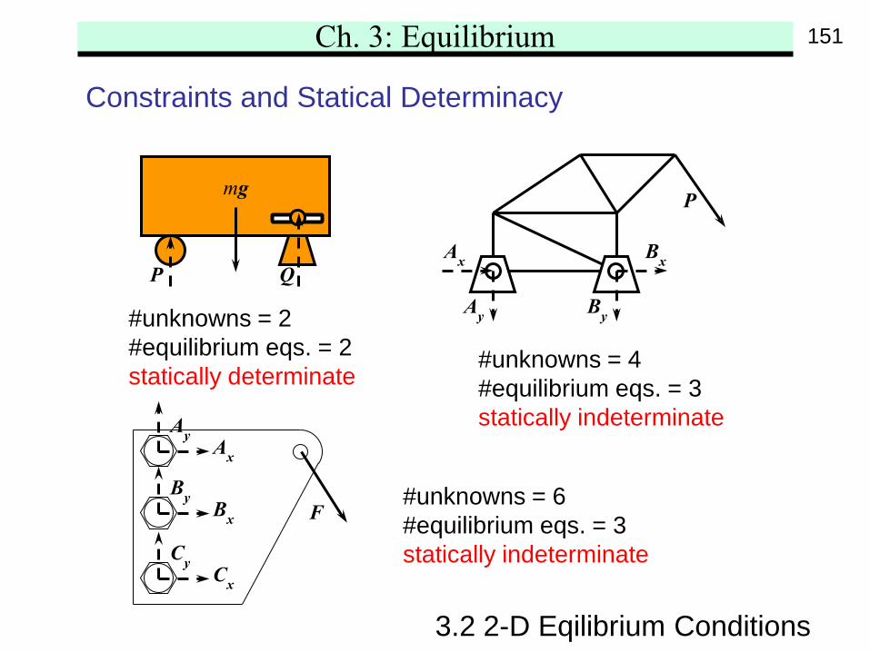
The equilibrium equations may not always solve allunknowns in the problem. Simply put, if #unknowns(including geometrical variables) > #equations, then wecannot solve it. This is because the system has moreconstraints than necessary to maintain the equilibruim.This is call statically indeterminate system. Extraequations, from force-deformation material properties,must also be applied to solve the redundant constraints.
150
Ch. 3: Equilibrium
3.2 2-D Eqilibrium Conditions
Constraints and Statical Determinacy
P Q
mg
#unknowns = 2#equilibrium eqs. = 2statically determinate
P
Ax
Ay
Bx
By
FBx
By
Ax
Ay
Cx
Cy
#unknowns = 4#equilibrium eqs. = 3statically indeterminate
#unknowns = 6#equilibrium eqs. = 3statically indeterminate
151
Ch. 3: Equilibrium
3.2 2-D Eqilibrium Conditions
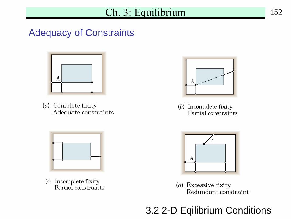
Adequacy of Constraints
152
Ch. 3: Equilibrium
3.2 2-D Eqilibrium Conditions
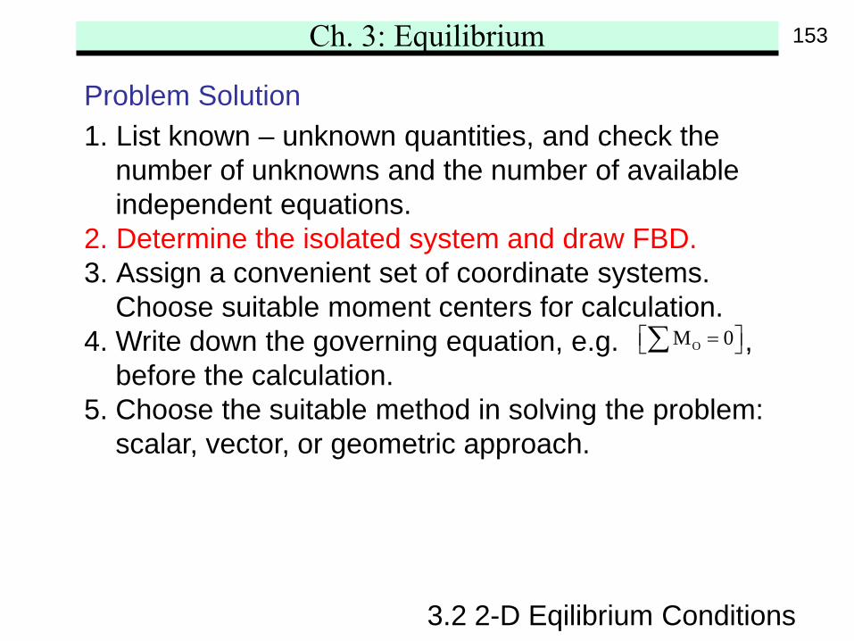
Problem Solution1. List known – unknown quantities, and check the
number of unknowns and the number of availableindependent equations.
2. Determine the isolated system and draw FBD.3. Assign a convenient set of coordinate systems.
Choose suitable moment centers for calculation.4. Write down the governing equation, e.g. ,
before the calculation.5. Choose the suitable method in solving the problem:
scalar, vector, or geometric approach.
OM 0 = ∑
153
Ch. 3: Equilibrium
3.2 2-D Eqilibrium Conditions
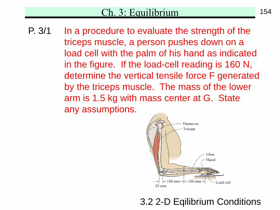
P. 3/1 In a procedure to evaluate the strength of thetriceps muscle, a person pushes down on aload cell with the palm of his hand as indicatedin the figure. If the load-cell reading is 160 N,determine the vertical tensile force F generatedby the triceps muscle. The mass of the lowerarm is 1.5 kg with mass center at G. Stateany assumptions.
154
Ch. 3: Equilibrium
3.2 2-D Eqilibrium Conditions
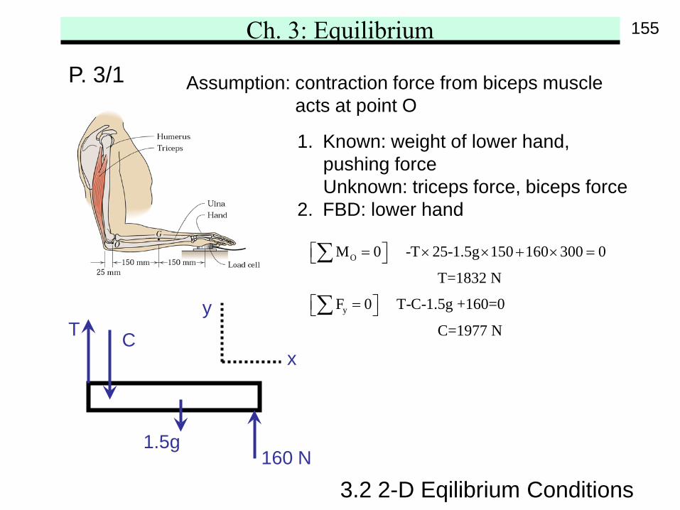
P. 3/1 Assumption: contraction force from biceps muscleacts at point O
1. Known: weight of lower hand,pushing forceUnknown: triceps force, biceps force
2. FBD: lower hand
y
x
O
y
M 0 -T 25-1.5g 150 160 300 0
T=1832 N
F 0 T-C-1.5g +160=0
C=1977 N
= × × + × =
=
∑
∑CT
160 N1.5g
155
Ch. 3: Equilibrium
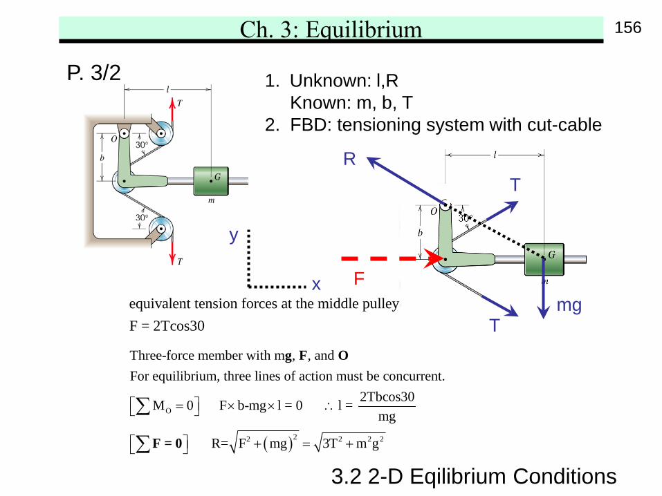
equivalent tension forces at the middle pulleyF = 2Tcos30
3.2 2-D Eqilibrium Conditions
P. 3/2 1. Unknown: l,RKnown: m, b, T
2. FBD: tensioning system with cut-cable
y
x
( )
O
22 2 2 2
Three-force member with m , , and For equilibrium, three lines of action must be concurrent.
2Tbcos30M 0 F b-mg l = 0 l = mg
R= F mg 3T m g
= × × ∴
+ = +
∑
∑
g F O
F = 0
F
RT
Tmg
156
Ch. 3: Equilibrium
3.2 2-D Eqilibrium Conditions
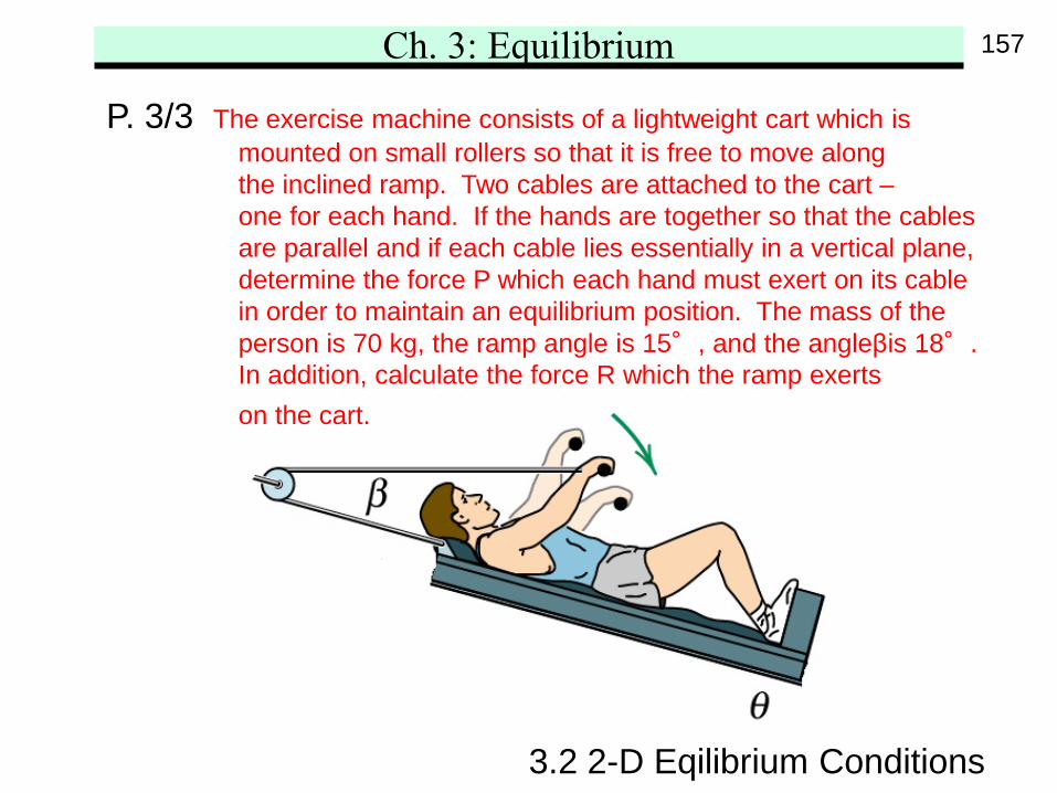
P. 3/3 The exercise machine consists of a lightweight cart which ismounted on small rollers so that it is free to move alongthe inclined ramp. Two cables are attached to the cart –one for each hand. If the hands are together so that the cablesare parallel and if each cable lies essentially in a vertical plane,determine the force P which each hand must exert on its cablein order to maintain an equilibrium position. The mass of theperson is 70 kg, the ramp angle is 15°, and the angleβis 18°.In addition, calculate the force R which the ramp exertson the cart.
157
Ch. 3: Equilibrium
3.2 2-D Eqilibrium Conditions
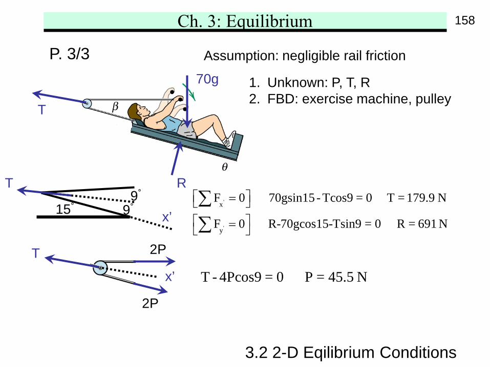
P. 3/3 Assumption: negligible rail friction
'
'
x
y
F 0 70gsin15 - Tcos9 = 0 T = 179.9 N
F 0 R-70gcos15-Tsin9 = 0 R = 691 N
= =
∑∑
T - 4Pcos9 = 0 P = 45.5 N
2P
2P
x’
T
T
70g
R
1. Unknown: P, T, R2. FBD: exercise machine, pulley
x’15° 9°9°
T
158
Ch. 3: Equilibrium
3.2 2-D Eqilibrium Conditions
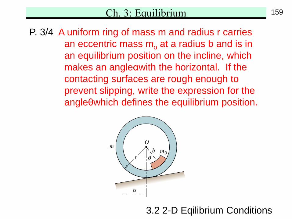
P. 3/4 A uniform ring of mass m and radius r carriesan eccentric mass mo at a radius b and is inan equilibrium position on the incline, whichmakes an angleαwith the horizontal. If thecontacting surfaces are rough enough toprevent slipping, write the expression for theangleθwhich defines the equilibrium position.
159
Ch. 3: Equilibrium
3.2 2-D Eqilibrium Conditions
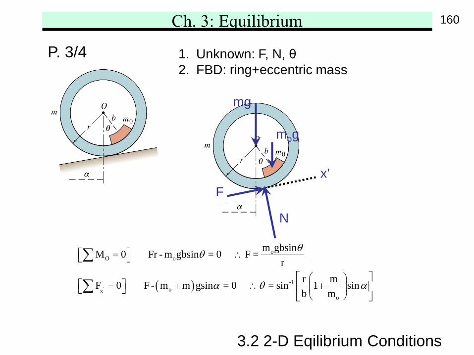
P. 3/4 1. Unknown: F, N, θ2. FBD: ring+eccentric mass
( )'
oO o
-1ox
o
m gbsinM 0 Fr - m gbsin = 0 F =r
r mF 0 F - m m gsin = 0 = sin 1 sinb m
θθ
α θ α
= ∴
= + ∴ +
∑
∑
x’
mg
mog
F
N
160
Ch. 3: Equilibrium
3.2 2-D Eqilibrium Conditions
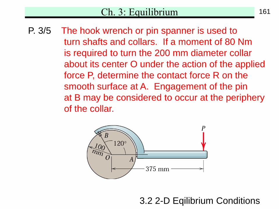
P. 3/5 The hook wrench or pin spanner is used toturn shafts and collars. If a moment of 80 Nmis required to turn the 200 mm diameter collarabout its center O under the action of the appliedforce P, determine the contact force R on thesmooth surface at A. Engagement of the pinat B may be considered to occur at the peripheryof the collar.
161
Ch. 3: Equilibrium
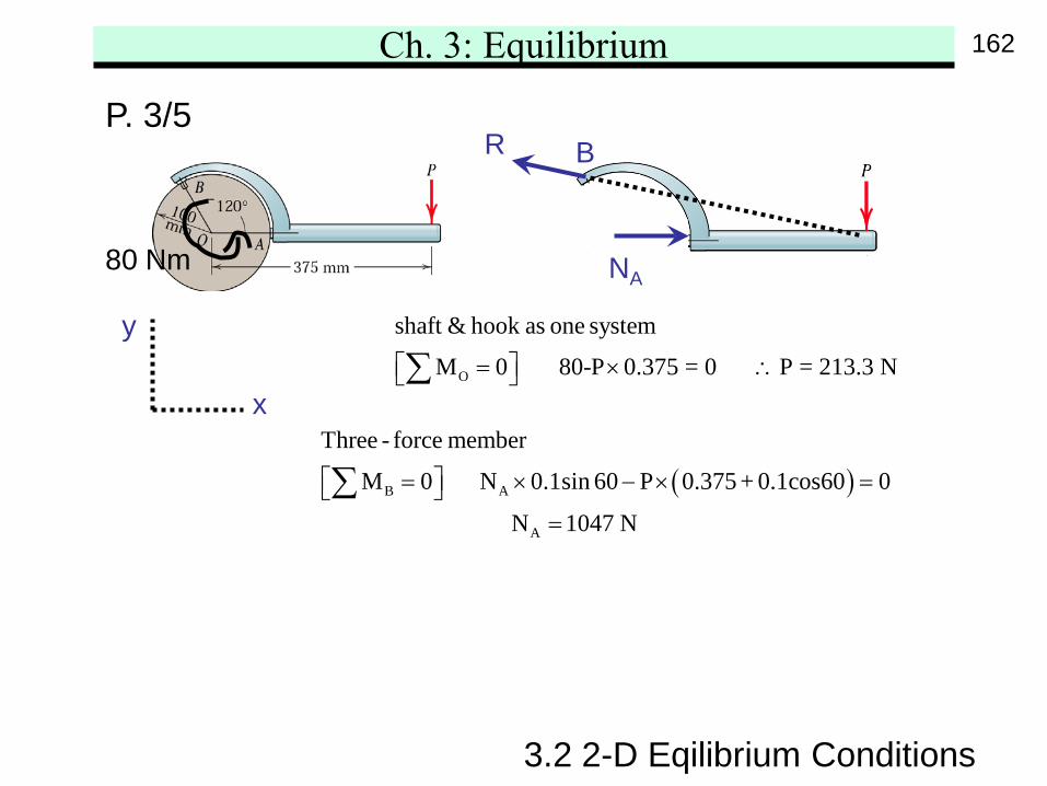
( )B A
A
Three - force member
M 0 N 0.1sin 60 P 0.375 + 0.1cos60 0
N 1047 N
= × − × = =
∑
3.2 2-D Eqilibrium Conditions
P. 3/5
O
shaft & hook as one system
M 0 80-P 0.375 = 0 P = 213.3 N = × ∴ ∑y
x
NA
R B
80 Nm
162
Ch. 3: Equilibrium
3.2 2-D Eqilibrium Conditions
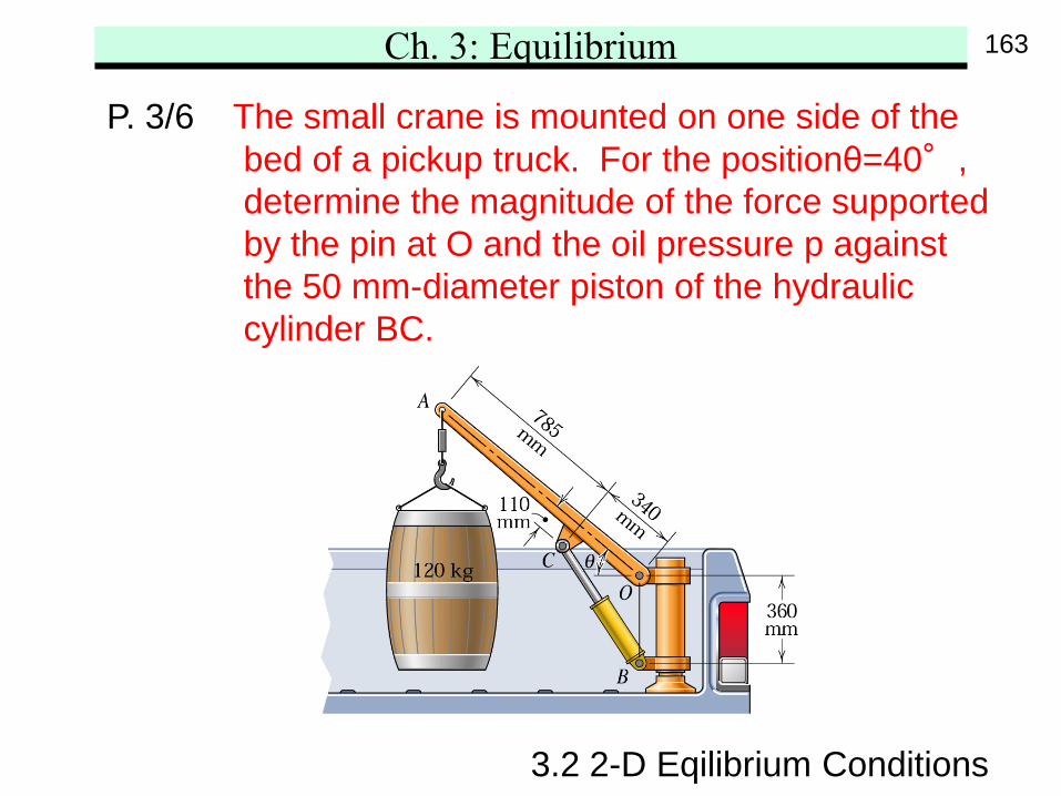
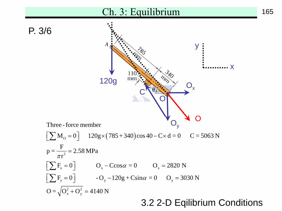
P. 3/6 The small crane is mounted on one side of thebed of a pickup truck. For the positionθ=40°,determine the magnitude of the force supportedby the pin at O and the oil pressure p againstthe 50 mm-diameter piston of the hydrauliccylinder BC.
163
Ch. 3: Equilibrium
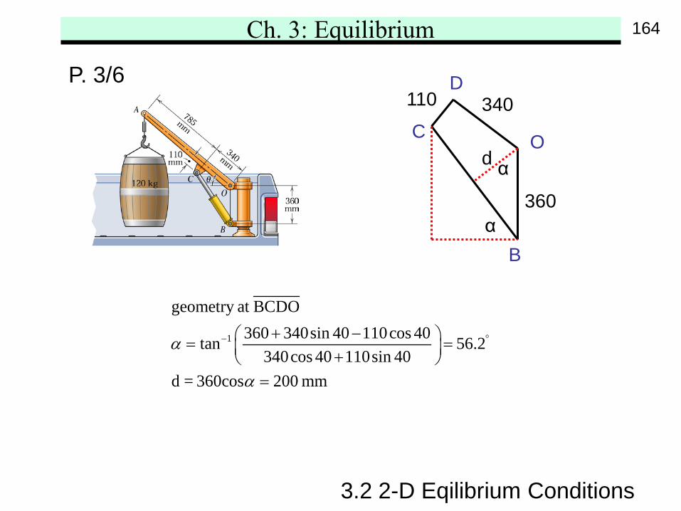
1
geometry at BCDO360 340sin 40 110cos 40tan 56.2
340cos 40 110sin 40d = 360cos 200 mm
α
α
− °+ − = = + =
3.2 2-D Eqilibrium Conditions
P. 3/6
B
C O
D
α
αd
360
110 340
164
Ch. 3: Equilibrium
3.2 2-D Eqilibrium Conditions
( )O
2
x x x
y y y
2 2x y
Three - force member
M 0 120g 785 + 340 cos 40 C d = 0 C = 5063 N
Fp = 2.58 MPar
F 0 O Ccos = 0 O 2820 N
F 0 - O 120g + Csin = 0 O 3030 N
O = O O
πα
α
= × − ×
=
= − = = − =
+
∑
∑∑
4140 N=
P. 3/6y
x
O
Oy
Ox
O
C120g
165
Ch. 3: Equilibrium
3.2 2-D Eqilibrium Conditions
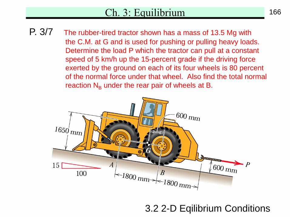
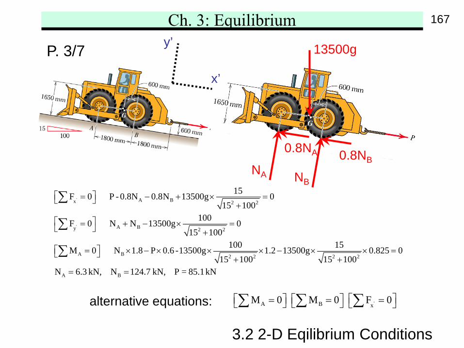
P. 3/7 The rubber-tired tractor shown has a mass of 13.5 Mg withthe C.M. at G and is used for pushing or pulling heavy loads.Determine the load P which the tractor can pull at a constantspeed of 5 km/h up the 15-percent grade if the driving forceexerted by the ground on each of its four wheels is 80 percentof the normal force under that wheel. Also find the total normalreaction NB under the rear pair of wheels at B.
166
Ch. 3: Equilibrium
'
'
A Bx 2 2
A By 2 2
A B 2 2 2 2
A B
15F 0 P - 0.8N 0.8N 13500g 015 100
100F 0 N N 13500g 015 100
100 15M 0 N 1.8 P 0.6 -13500g 1.2 13500g 0.825 015 100 15 100
N 6.3 kN, N 124.7 kN, P = 8
= − + × = +
= + − × = +
= × − × × × − × × = + += =
∑
∑
∑5.1 kN
3.2 2-D Eqilibrium Conditions
P. 3/7
'A B xM 0 M 0 F 0 = = = ∑ ∑ ∑
y’
x’
13500g
NA NB
0.8NA 0.8NB
alternative equations:
167
Ch. 3: Equilibrium
3.2 2-D Eqilibrium Conditions
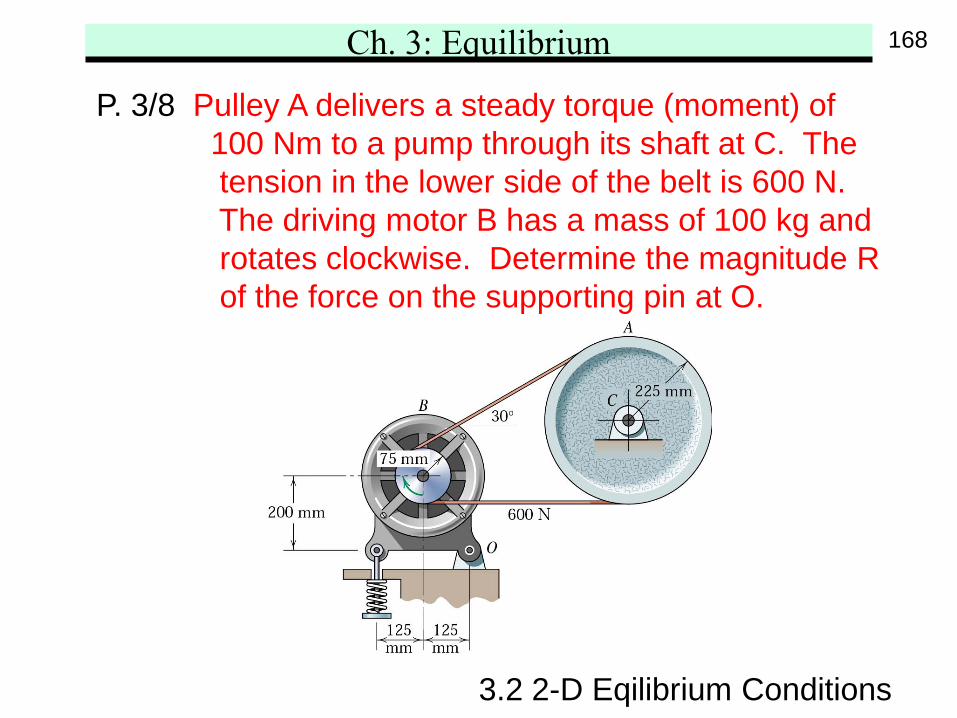
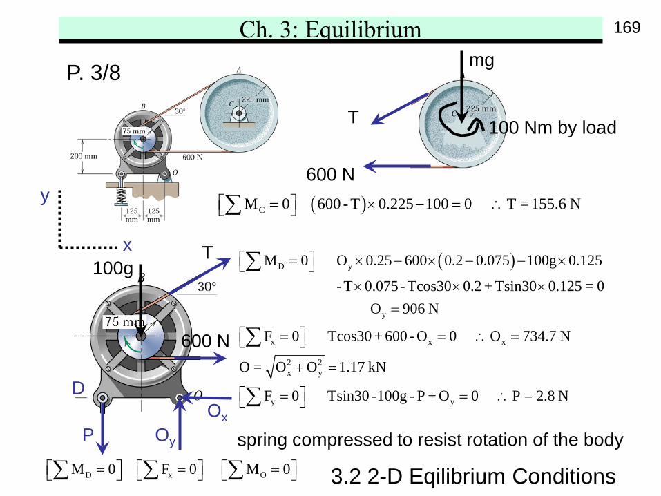
P. 3/8 Pulley A delivers a steady torque (moment) of100 Nm to a pump through its shaft at C. Thetension in the lower side of the belt is 600 N.The driving motor B has a mass of 100 kg androtates clockwise. Determine the magnitude Rof the force on the supporting pin at O.
168
Ch. 3: Equilibrium
3.2 2-D Eqilibrium Conditions
P. 3/8
( )CM 0 600 - T 0.225 100 0 T = 155.6 N = × − = ∴ ∑
( )D y
y
x x x
M 0 O 0.25 600 0.2 0.075 100g 0.125
- T 0.075 - Tcos30 0.2 + Tsin30 0.125 = 0 O 906 N
F 0 Tcos30 + 600 - O 0 O 734.7 N
O = O
= × − × − − × × × ×
=
= = ∴ =
∑
∑2 2x y
y y
O 1.17 kN
F 0 Tsin30 -100g - P + O 0 P = 2.8 N
+ =
= = ∴ ∑
600 N
T 100 Nm by load
mg
y
x
OxOy
600 N
T
P spring compressed to resist rotation of the body
100g
D
D x OM 0 F 0 M 0 = = = ∑ ∑ ∑
169
Ch. 3: Equilibrium
3.2 2-D Eqilibrium Conditions
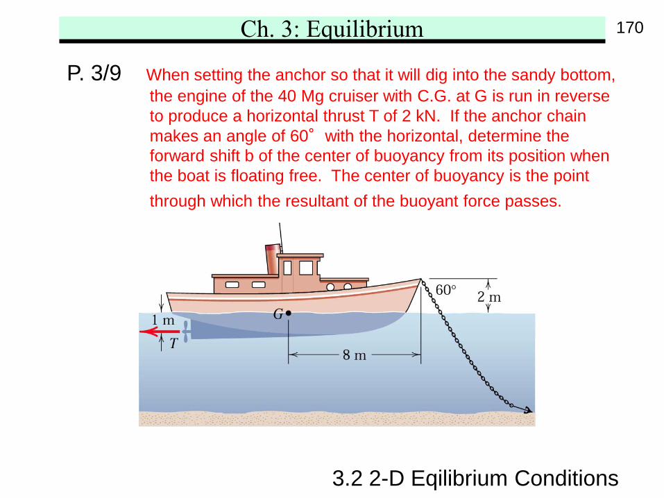
P. 3/9 When setting the anchor so that it will dig into the sandy bottom,the engine of the 40 Mg cruiser with C.G. at G is run in reverseto produce a horizontal thrust T of 2 kN. If the anchor chainmakes an angle of 60°with the horizontal, determine theforward shift b of the center of buoyancy from its position whenthe boat is floating free. The center of buoyancy is the pointthrough which the resultant of the buoyant force passes.
170
Ch. 3: Equilibrium
3.2 2-D Eqilibrium Conditions
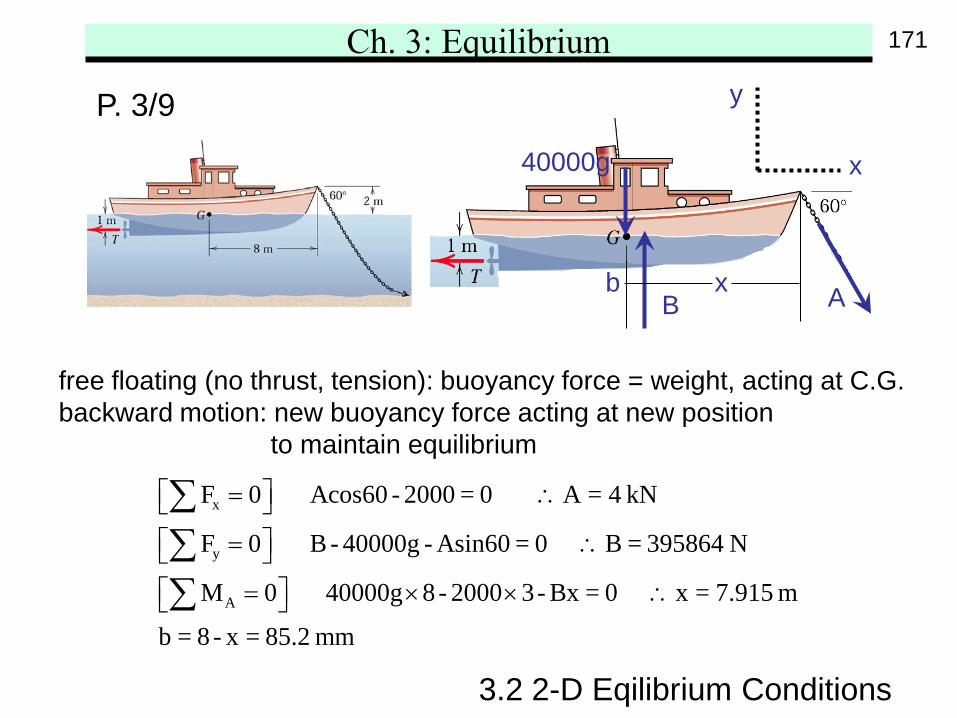
P. 3/9 y
x
x
y
A
F 0 Acos60 - 2000 = 0 A = 4 kN
F 0 B - 40000g - Asin60 = 0 B = 395864 N
M 0 40000g 8 - 2000 3- Bx = 0 x = 7.915 m
b = 8- x = 85.2 mm
= ∴ = ∴ = × × ∴
∑∑∑
free floating (no thrust, tension): buoyancy force = weight, acting at C.G.backward motion: new buoyancy force acting at new position
to maintain equilibrium
40000g
ABxb
171
Ch. 3: Equilibrium
3.2 2-D Eqilibrium Conditions
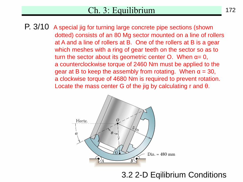
P. 3/10 A special jig for turning large concrete pipe sections (showndotted) consists of an 80 Mg sector mounted on a line of rollersat A and a line of rollers at B. One of the rollers at B is a gearwhich meshes with a ring of gear teeth on the sector so as toturn the sector about its geometric center O. When α= 0,a counterclockwise torque of 2460 Nm must be applied to thegear at B to keep the assembly from rotating. When α = 30,a clockwise torque of 4680 Nm is required to prevent rotation.Locate the mass center G of the jig by calculating r and θ.
172
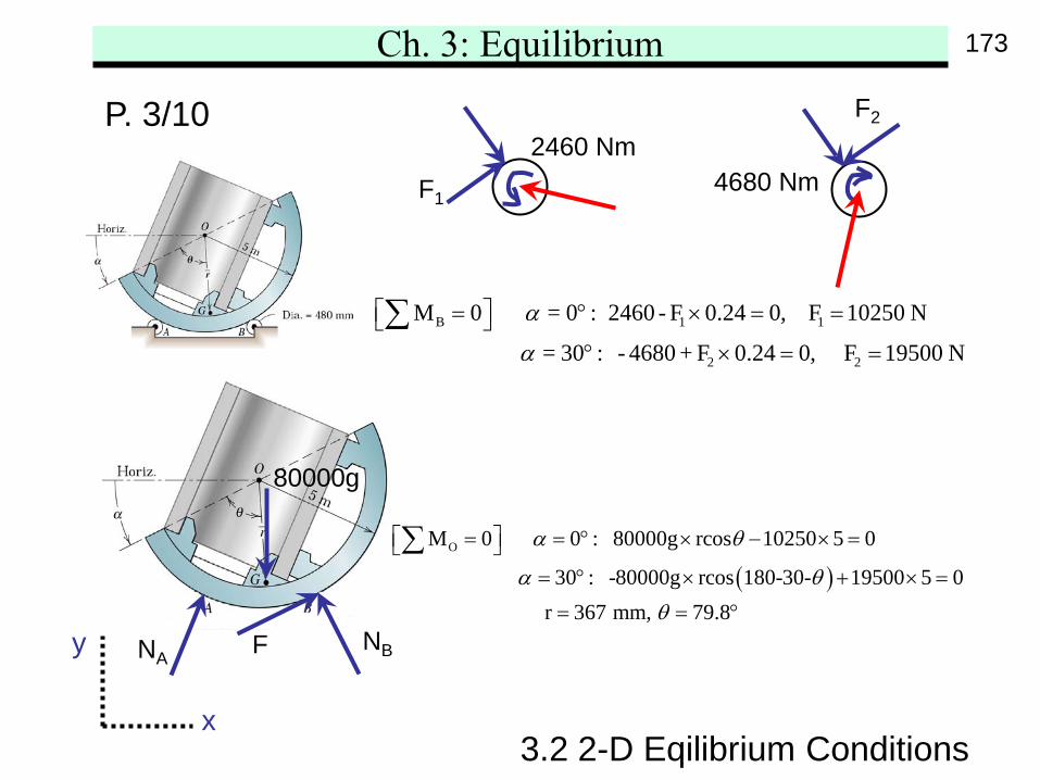
Ch. 3: Equilibrium
B 1 1
2 2
M 0 = 0 : 2460 - F 0.24 0, F 10250 N
= 30 : - 4680 + F 0.24 0, F 19500 N
α
α
= ° × = = ° × = =
∑
3.2 2-D Eqilibrium Conditions
P. 3/10
y
x
( )OM 0 0 : 80000g rcos 10250 5 0
30 : -80000g rcos 180-30- 19500 5 0 r 367 mm, 79.8
α θ
α θθ
= = ° × − × = = ° × + × =
= = °
∑
2460 NmF1
4680 Nm
F2
NANBF
80000g
173
Ch. 3: Equilibrium
3.3 3-D Eqilibrium Conditions
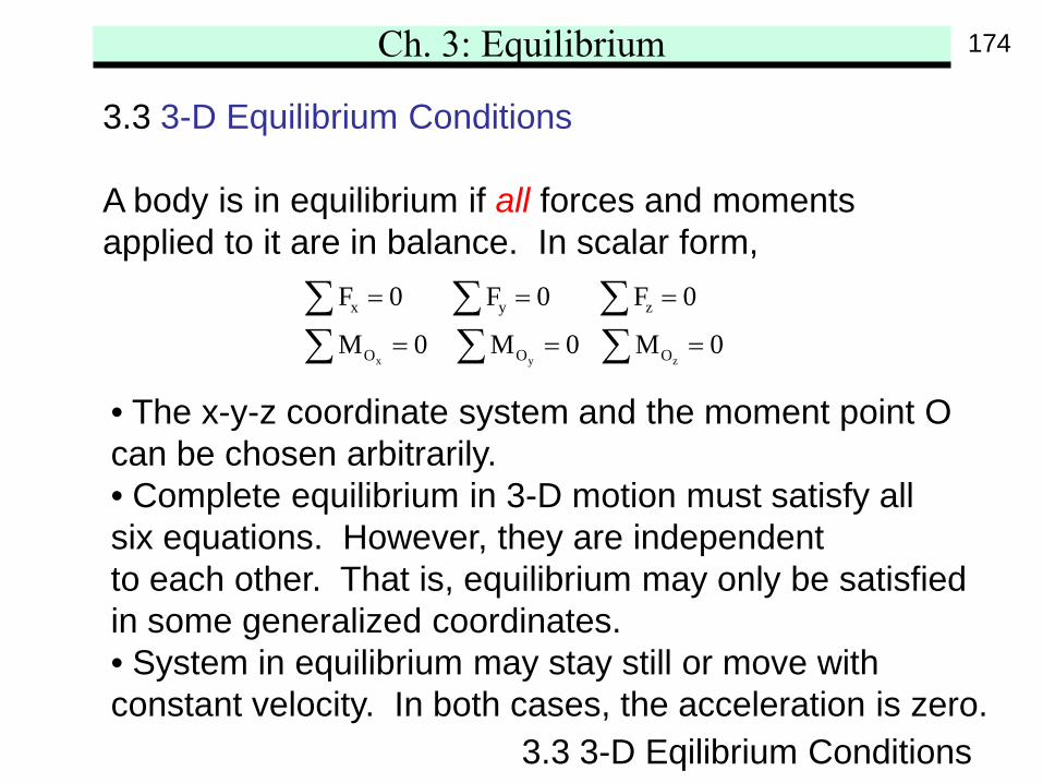
3.3 3-D Equilibrium Conditions
A body is in equilibrium if all forces and momentsapplied to it are in balance. In scalar form,
x y z
x y z
O O O
F 0 F 0 F 0
M 0 M 0 M 0
= = =
= = =∑ ∑ ∑∑ ∑ ∑
• The x-y-z coordinate system and the moment point Ocan be chosen arbitrarily.• Complete equilibrium in 3-D motion must satisfy allsix equations. However, they are independentto each other. That is, equilibrium may only be satisfiedin some generalized coordinates.• System in equilibrium may stay still or move withconstant velocity. In both cases, the acceleration is zero.
174
Ch. 3: Equilibrium
3.3 3-D Eqilibrium Conditions
175
Ch. 3: Equilibrium
3.3 3-D Eqilibrium Conditions
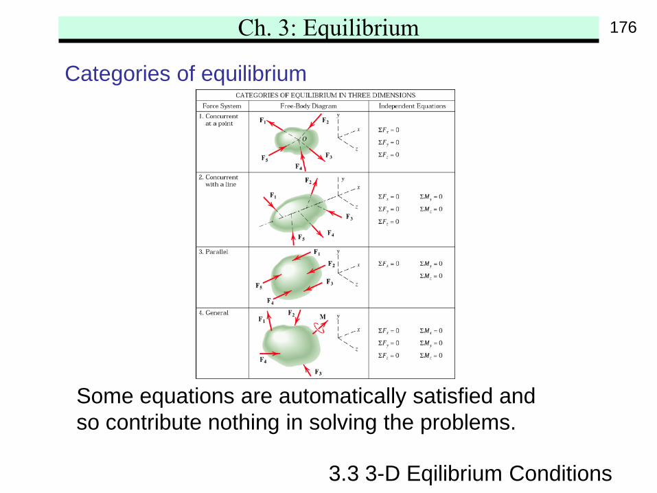
Categories of equilibrium
Some equations are automatically satisfied andso contribute nothing in solving the problems.
176

Ch. 3: Equilibrium
3.3 3-D Eqilibrium Conditions
Constraints and Statical Determinacy
The equilibrium equations may not always solve allunknowns in the problem. Simply put, if #unknowns(including geometrical variables) > #equations, then wecannot solve it. This is because the system has moreconstraints than necessary to maintain the equilibrium.This is call statically indeterminate system. Extraequations, from force-deformation material properties,must also be applied to solve the redundant constraints.
177
Ch. 3: Equilibrium
3.3 3-D Eqilibrium Conditions
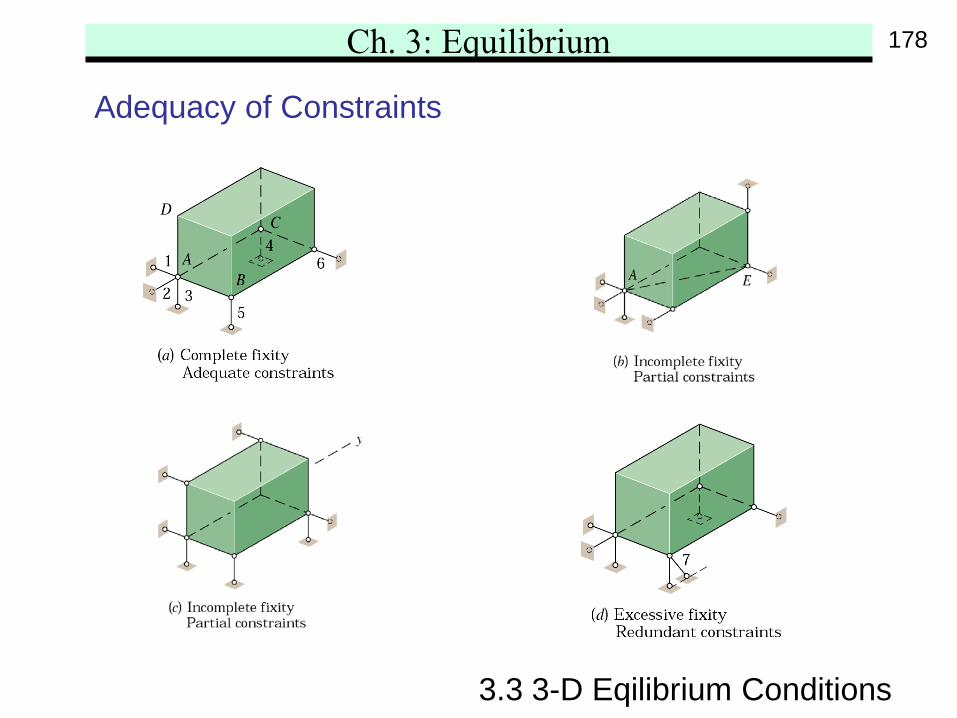
Adequacy of Constraints
178
Ch. 3: Equilibrium
3.3 3-D Eqilibrium Conditions
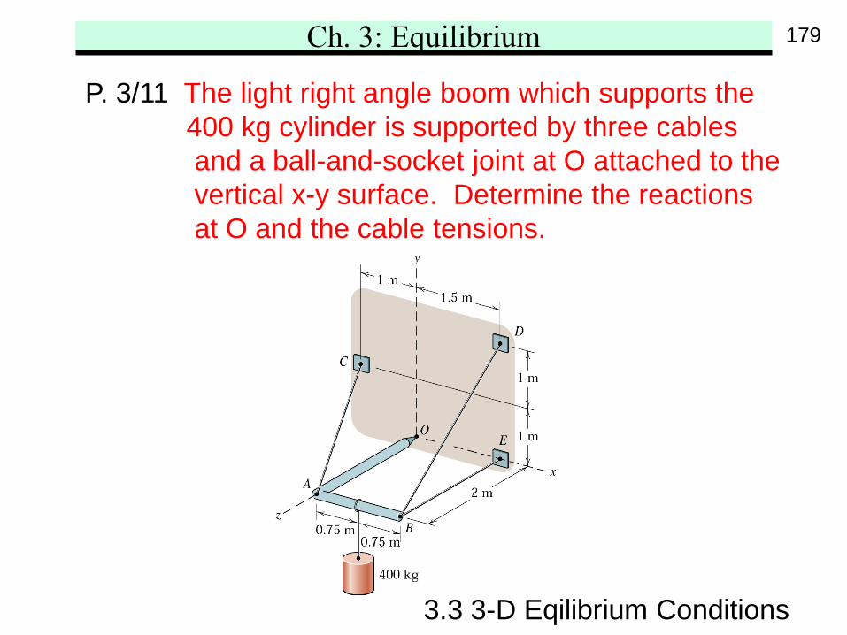
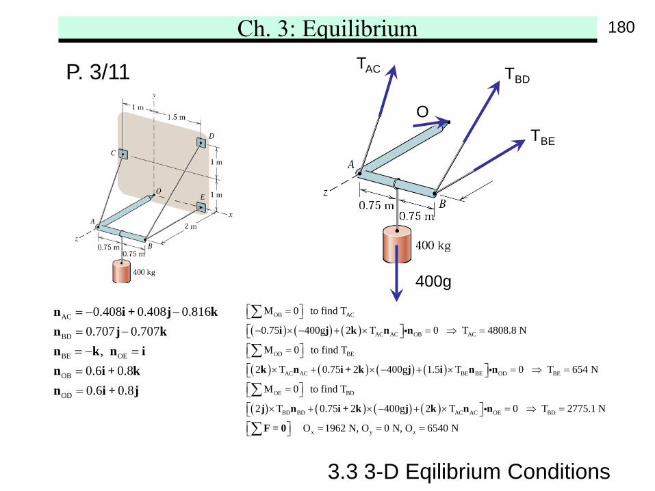
P. 3/11 The light right angle boom which supports the400 kg cylinder is supported by three cablesand a ball-and-socket joint at O attached to thevertical x-y surface. Determine the reactionsat O and the cable tensions.
179
Ch. 3: Equilibrium
AC
BD
BE OE
OB
OD
0.408 0.408 0.8160.707 0.707
, 0.6 0.80.6 0.8
= − −= −= − ===
n i + j kn j kn k n in i + kn i + j
3.3 3-D Eqilibrium Conditions
P. 3/11
( ) ( ) ( )
( ) ( ) ( ) ( )
( ) ( )
OB AC
AC AC OB AC
OD BE
AC AC BE BE OD BE
OE BD
BD BD
M 0 to find T
0.75 400g 2 T 0 T 4808.8 N
M 0 to find T
2 T 0.75 2 400g 1.5 T 0 T 654 N
M 0 to find T
2 T 0.75 2 40
= − × − + × = ⇒ =
= × + × − + × = ⇒ =
= × + × −
∑
∑
∑
i j k n n
k n i + k j i n n
j n i + k
( ) ( ) AC AC OE BD
x y z
0g 2 T 0 T 2775.1 N
O 1962 N, O 0 N, O 6540 N
+ × = ⇒ = = = = ∑
j k n n
F = 0
400g
OTBE
TBDTAC
180
Ch. 3: Equilibrium
3.3 3-D Eqilibrium Conditions
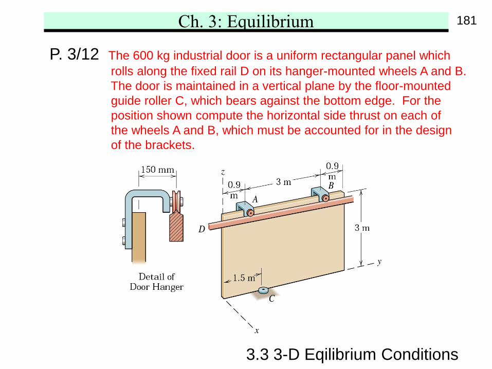
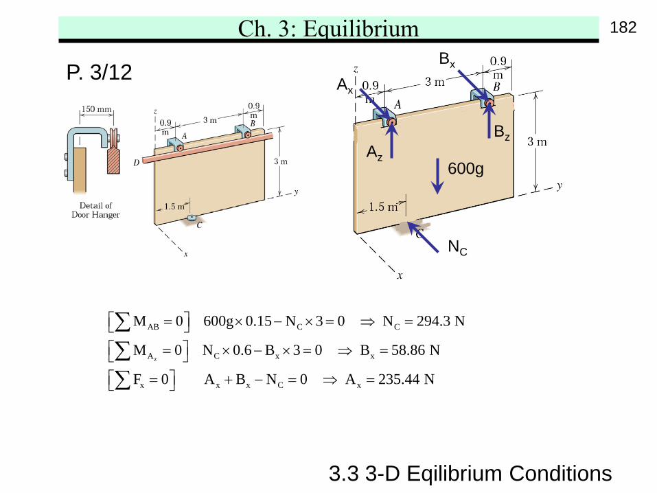
P. 3/12 The 600 kg industrial door is a uniform rectangular panel whichrolls along the fixed rail D on its hanger-mounted wheels A and B.The door is maintained in a vertical plane by the floor-mountedguide roller C, which bears against the bottom edge. For theposition shown compute the horizontal side thrust on each ofthe wheels A and B, which must be accounted for in the designof the brackets.
181
Ch. 3: Equilibrium
3.3 3-D Eqilibrium Conditions
P. 3/12
z
AB C C
A C x x
x x x C x
M 0 600g 0.15 N 3 0 N 294.3 N
M 0 N 0.6 B 3 0 B 58.86 N
F 0 A B N 0 A 235.44 N
= × − × = ⇒ = = × − × = ⇒ = = + − = ⇒ =
∑∑∑
NC
Ax
Az
Bz
Bx
600g
182
Ch. 3: Equilibrium
3.3 3-D Eqilibrium Conditions
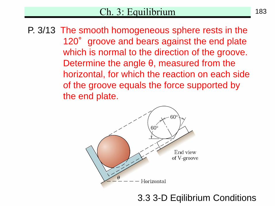
P. 3/13 The smooth homogeneous sphere rests in the120°groove and bears against the end platewhich is normal to the direction of the groove.Determine the angle θ, measured from thehorizontal, for which the reaction on each sideof the groove equals the force supported bythe end plate.
183
Ch. 3: Equilibrium
3.3 3-D Eqilibrium Conditions
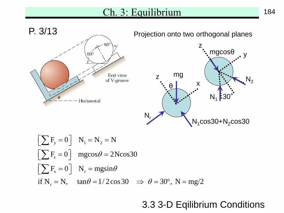
P. 3/13 Projection onto two orthogonal planes
y 1 2
z
x r
r
F 0 N N N
F 0 mgcos 2Ncos30
F 0 N mgsin
if N N, tan 1/ 2cos30 30 , N mg/2
θ
θ
θ θ
= = = = = = =
= = ⇒ = ° =
∑∑∑
x
yz
z mg
mgcosθ
θ
Nr
N2
N1
N1cos30+N2cos30
30°
184
Ch. 3: Equilibrium
3.3 3-D Eqilibrium Conditions
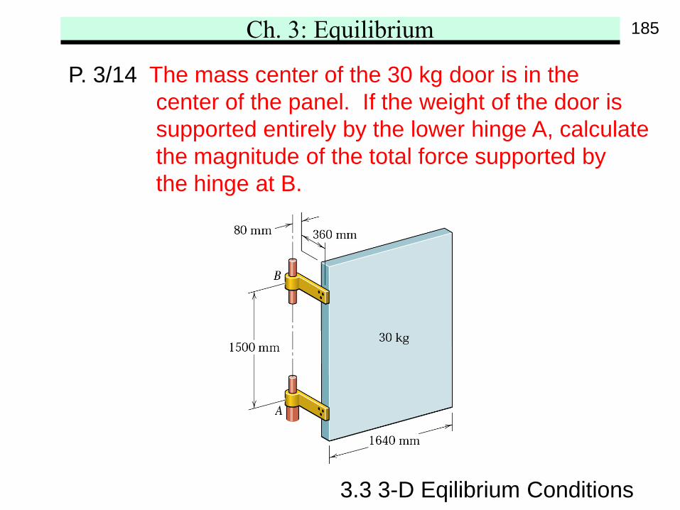
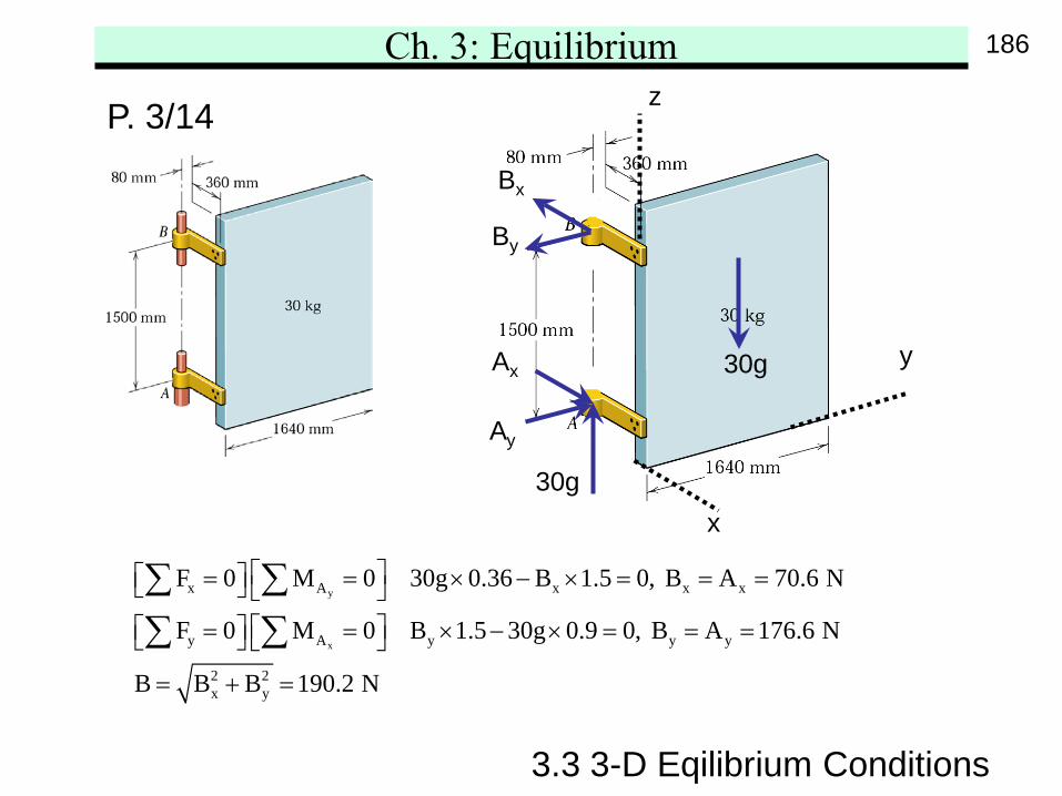
P. 3/14 The mass center of the 30 kg door is in thecenter of the panel. If the weight of the door issupported entirely by the lower hinge A, calculatethe magnitude of the total force supported bythe hinge at B.
185
Ch. 3: Equilibrium
3.3 3-D Eqilibrium Conditions
P. 3/14
y
x
x A x x x
y A y y y
2 2x y
F 0 M 0 30g 0.36 B 1.5 0, B A 70.6 N
F 0 M 0 B 1.5 30g 0.9 0, B A 176.6 N
B B B 190.2 N
= = × − × = = = = = × − × = = =
= + =
∑ ∑∑ ∑
30g
30gx
y
z
Ay
By
Bx
Ax
186
Ch. 3: Equilibrium
3.3 3-D Eqilibrium Conditions
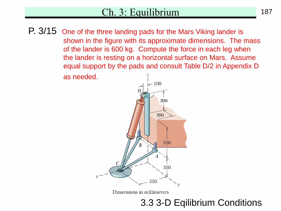
P. 3/15 One of the three landing pads for the Mars Viking lander isshown in the figure with its approximate dimensions. The massof the lander is 600 kg. Compute the force in each leg whenthe lander is resting on a horizontal surface on Mars. Assumeequal support by the pads and consult Table D/2 in Appendix Das needed.
187
Ch. 3: Equilibrium
3.3 3-D Eqilibrium Conditions
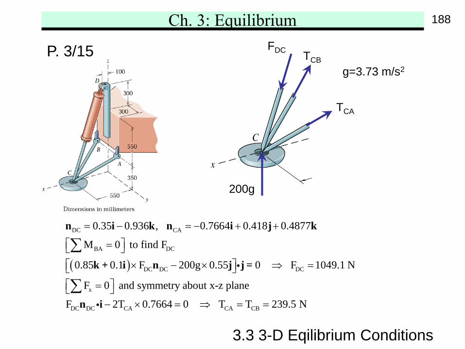
P. 3/15
( )
DC CA
BA DC
DC DC DC
x
DC DC CA CA CB
0.35 0.936 , 0.7664 0.418 0.4877
M 0 to find F
0.85 0.1 F 200g 0.55 0 F 1049.1 N
F 0 and symmetry about x-z plane
F 2T 0.7664 0 T T 239
= − = − + +
= × − × ⇒ =
= − × = ⇒ = =
∑
∑
n i k n i j k
k + i n j j =
n i
.5 N
g=3.73 m/s2
200g
FDC TCB
TCA
188
Ch. 3: Equilibrium
3.3 3-D Eqilibrium Conditions
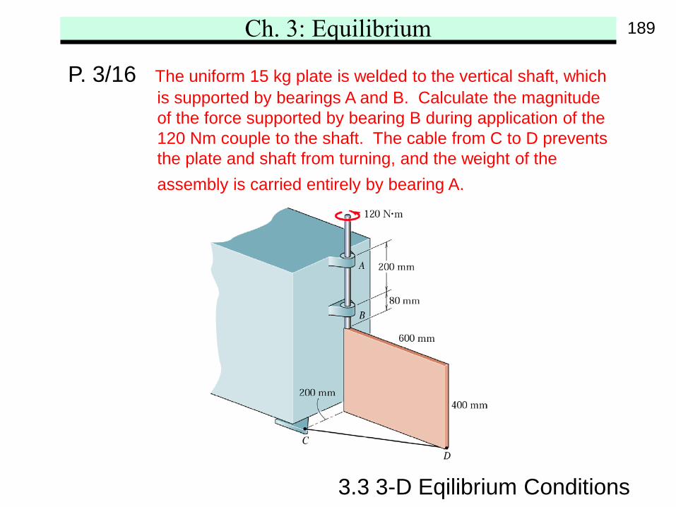
P. 3/16 The uniform 15 kg plate is welded to the vertical shaft, whichis supported by bearings A and B. Calculate the magnitudeof the force supported by bearing B during application of the120 Nm couple to the shaft. The cable from C to D preventsthe plate and shaft from turning, and the weight of theassembly is carried entirely by bearing A.
189
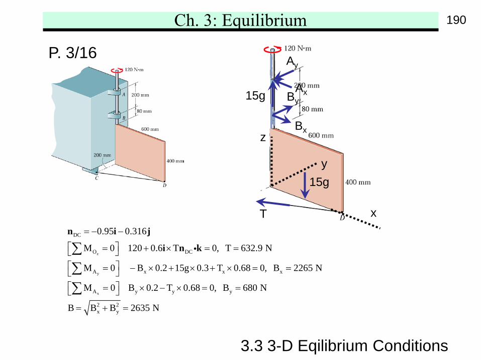
Ch. 3: Equilibrium
z
y
x
DC
O DC
A x x x
A y y y
2 2x y
0.95 0.316
M 0 120 0.6 T 0, T 632.9 N
M 0 B 0.2 15g 0.3 T 0.68 0, B 2265 N
M 0 B 0.2 T 0.68 0, B 680 N
B B B 2635 N
= − −
= + × = = = − × + × + × = = = × − × = =
= + =
∑∑∑
n i j
i n k
3.3 3-D Eqilibrium Conditions
P. 3/16
x
y
z
T
15g
Bx
By
Ay
Ax15g
190
Ch. 3: Equilibrium
3.3 3-D Eqilibrium Conditions
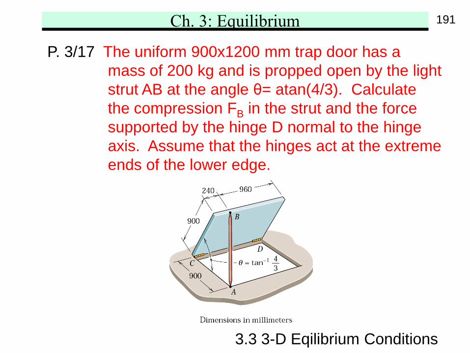
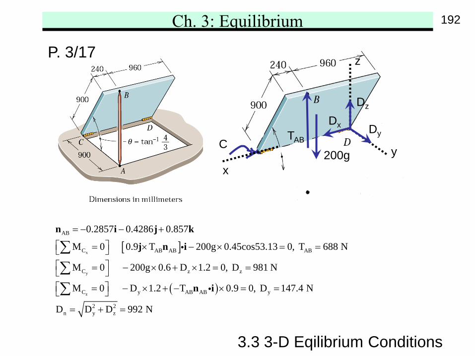
P. 3/17 The uniform 900x1200 mm trap door has amass of 200 kg and is propped open by the lightstrut AB at the angle θ= atan(4/3). Calculatethe compression FB in the strut and the forcesupported by the hinge D normal to the hingeaxis. Assume that the hinges act at the extremeends of the lower edge.
191
Ch. 3: Equilibrium
[ ]
( )
x
y
z
AB
C AB AB AB
C z z
C y AB AB y
2 2n y z
0.2857 0.4286 0.857
M 0 0.9 T 200g 0.45cos53.13 0, T 688 N
M 0 200g 0.6 D 1.2 0, D 981 N
M 0 D 1.2 T 0.9 0, D 147.4 N
D D D 992 N
= − − +
= × − × = = = − × + × = = = − × + − × = =
= + =
∑∑∑
n i j k
j n i
n i
3.3 3-D Eqilibrium Conditions
P. 3/17
xy
z
DyDx
Dz
200gC
TAB
192
Ch. 3: Equilibrium
3.3 3-D Eqilibrium Conditions
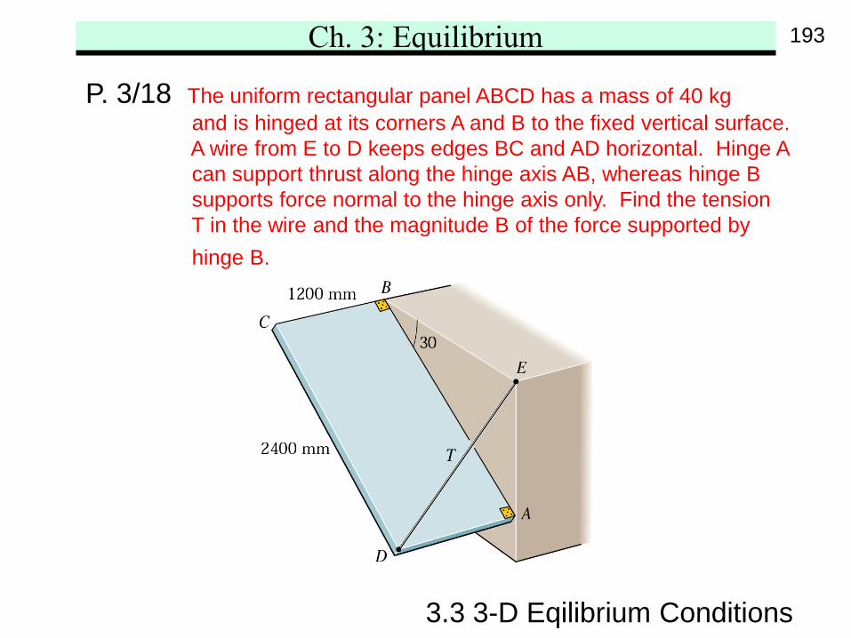
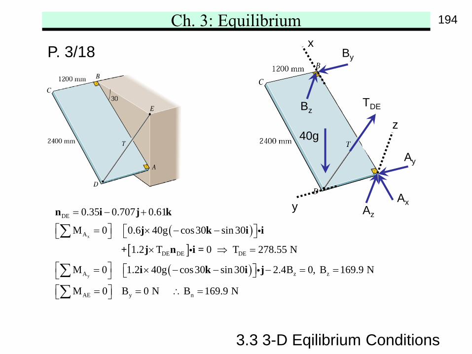
P. 3/18 The uniform rectangular panel ABCD has a mass of 40 kgand is hinged at its corners A and B to the fixed vertical surface.A wire from E to D keeps edges BC and AD horizontal. Hinge Acan support thrust along the hinge axis AB, whereas hinge Bsupports force normal to the hinge axis only. Find the tensionT in the wire and the magnitude B of the force supported byhinge B.
193
Ch. 3: Equilibrium
3.3 3-D Eqilibrium Conditions
P. 3/18
( )[ ]
( )
x
y
DE
A
DE DE DE
A z z
AE y
0.35 0.707 0.61
M 0 0.6 40g cos30 sin 30
1.2 T 0 T 278.55 N
M 0 1.2 40g cos30 sin 30 2.4B 0, B 169.9 N
M 0 B 0 N
= − +
= × − − × ⇒ =
= × − − − = = = =
∑
∑∑
n i j k
j k i i
+ j n i =
i k i j
n B 169.9 N∴ =
40g
y
x
z
TDE
Az
Ay
Ax
Bz
By
194
Ch. 3: Equilibrium
3.3 3-D Eqilibrium Conditions
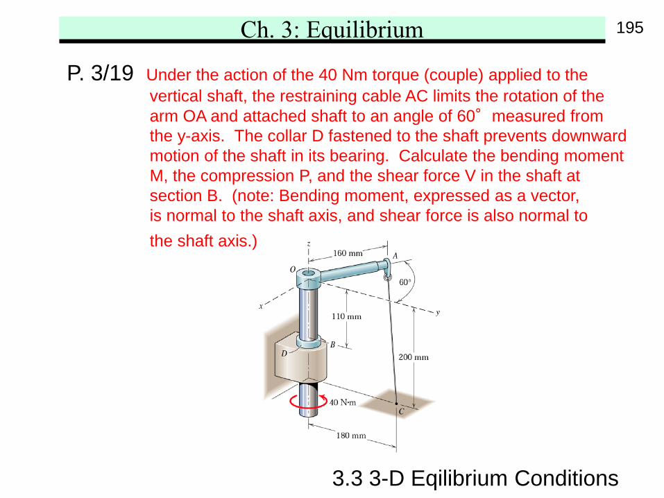
P. 3/19 Under the action of the 40 Nm torque (couple) applied to thevertical shaft, the restraining cable AC limits the rotation of thearm OA and attached shaft to an angle of 60°measured fromthe y-axis. The collar D fastened to the shaft prevents downwardmotion of the shaft in its bearing. Calculate the bending momentM, the compression P, and the shear force V in the shaft atsection B. (note: Bending moment, expressed as a vector,is normal to the shaft axis, and shear force is also normal tothe shaft axis.)
195
Ch. 3: Equilibrium
3.3 3-D Eqilibrium Conditions
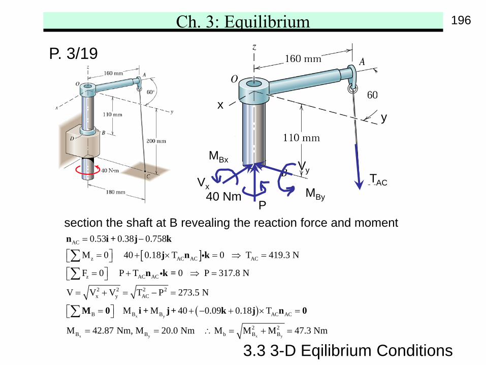
P. 3/19
section the shaft at B revealing the reaction force and moment
[ ]
( )x y
x y
AC
z AC AC AC
z AC AC
2 2 2 2x y AC
B B B AC AC
B B
0.53 0.38 0.758
M 0 40 0.18 T 0 T 419.3 N
F 0 P T 0 P 317.8 N
V V V T P 273.5 N
M M 40 0.09 0.18 T
M 42.87 Nm, M 20.0
= −
= + × = ⇒ = = + ⇒ =
= + = − =
= + − + × =
= =
∑∑
∑
n i + j k
j n k
n k =
M 0 i + j+ k j n 0
x y
2 2b B B Nm M M M 47.3 Nm∴ = + =
xy
TAC
MBx
MBy40 NmP
Vx
Vy
196
Ch. 3: Equilibrium
3.3 3-D Eqilibrium Conditions
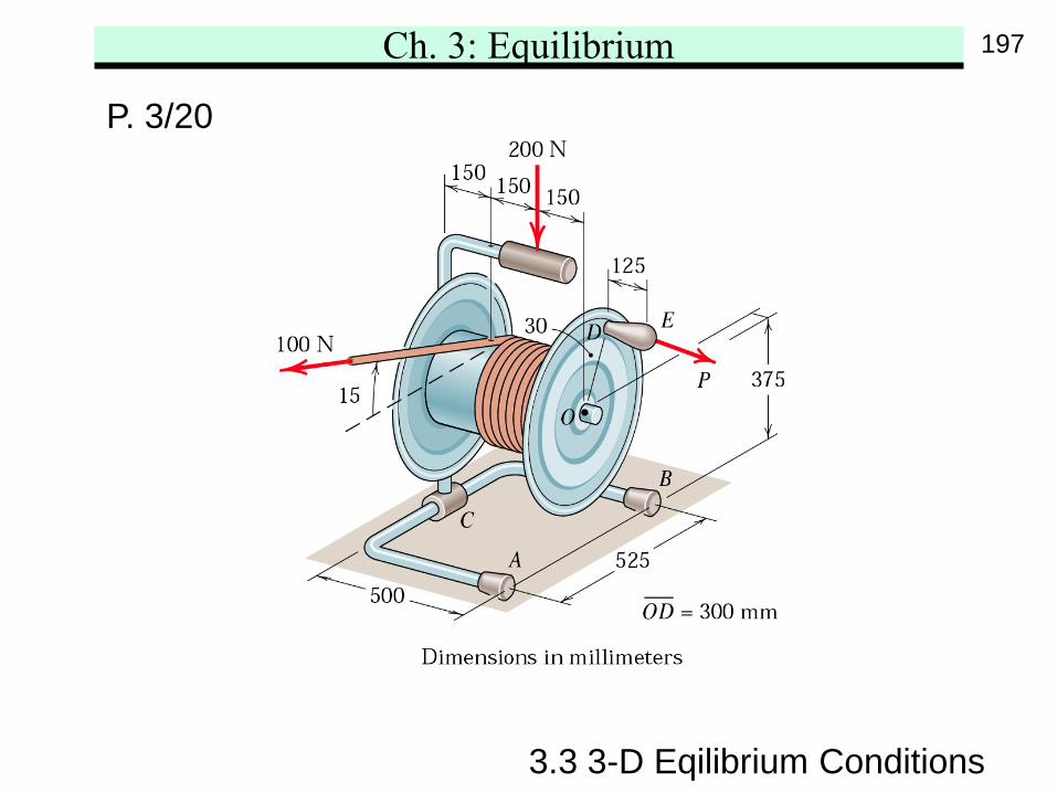
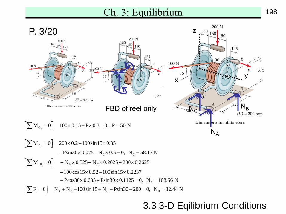
P. 3/20
197
Ch. 3: Equilibrium
yOM 0 100 0.15 P 0.3 0, P 50 N = × − × = = ∑
x
y
B
C C
B A C
M 0 200 0.2 100sin15 0.35
Psin30 0.075 N 0.5 0, N 58.13 N
M 0 N 0.525 N 0.2625 200 0.2625
100cos15 0.52 100sin15 0.2237
= × − × − × − × = =
= − × − × + × + × − ×
∑
∑
A
z A B C B
Pcos30 0.635 Psin30 0.1125 0, N 108.56 N
F 0 N N 100sin15 N Psin30 200 0, N 32.44 N
− × + × = =
= + + + − − = = ∑
3.3 3-D Eqilibrium Conditions
P. 3/20
FBD of reel only
x y
z
NA
NBNC
198
Ch. 3: Equilibrium
3.3 3-D Eqilibrium Conditions
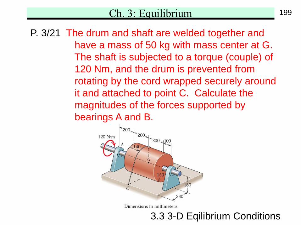
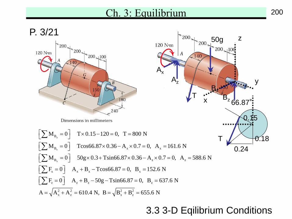
P. 3/21 The drum and shaft are welded together andhave a mass of 50 kg with mass center at G.The shaft is subjected to a torque (couple) of120 Nm, and the drum is prevented fromrotating by the cord wrapped securely aroundit and attached to point C. Calculate themagnitudes of the forces supported bybearings A and B.
199
Ch. 3: Equilibrium
y
z
x
B
B x x
B z z
x x x x
z
M 0 T 0.15 120 0, T 800 N
M 0 Tcos66.87 0.36 A 0.7 0, A 161.6 N
M 0 50g 0.3 Tsin66.87 0.36 A 0.7 0, A 588.6 N
F 0 A B Tcos66.87 0, B 152.6 N
F 0
= × − = = = × − × = = = × + × − × = = = + − = = =
∑∑∑∑∑ z z z
2 2 2 2x z x z
A B 50g Tsin66.87 0, B 637.6 N
A A A 610.4 N, B B B 655.6 N
+ − − = =
= + = = + =
3.3 3-D Eqilibrium Conditions
P. 3/21
0.180.24
0.15
66.87°
T
T
50g
Az
Ax
BxBzx
y
z
200
Ch. 3: Equilibrium
3.3 3-D Eqilibrium Conditions
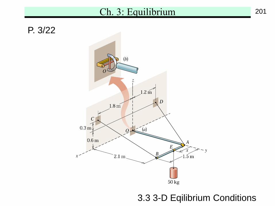
P. 3/22
201
Ch. 3: Equilibrium
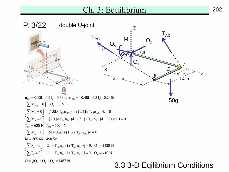
( ) ( )( ) ( )
BC AD
AB z
z BC BC AD AD
x BC BC AD AD
BC AD
y
0.13 0.91 0.39 , 0.48 0.84 0.241
M 0 O 0 N
M 0 1.8 T 2.1 T 0
M 0 2.1 T 2.1 T 50g 2.1 0
T 625 N, T 1024 N
M 0 M 50gx
= − + = − − +
= = = × + × = × + × − × =
= =
= + +
∑∑∑
∑
n i j k n i j k
i n k j n k =
j n i j n i
( )BC BC
y y BC BC AD AD y
x x BC BC AD AD x
2 2 2x y z
1.5 T 0
M 365.66 490.5
F 0 O T T 0, O 1429 N
F 0 O T T 0, O 410 N
O O O O 1487 N
x
×
= −
= + + = = = + + = =
= + + =
∑∑
i n j =
n j n j
n i n i
3.3 3-D Eqilibrium Conditions
P. 3/22 double U-joint
x
z
M
50g
TADTBC
Oz
OyOx
202
![[PPT]Financial Instruments, Markets and Institutionschaf/ba4345/trans/ch3.ppt · Web viewFinancial Instruments, Markets and Institutions Summary of Classification of Financial Markets](https://img.pdfslide.us/doc/110x75/5aa3fc217f8b9a7c1a8b862f/pptfinancial-instruments-markets-and-chafba4345transch3pptweb-viewfinancial.jpg)