Embed Size (px)
Citation preview
8/19/2019 Ch01 Standard Methods and Practises
http://slidepdf.com/reader/full/ch01-standard-methods-and-practises 1/44
Chap. 1 Standard Methods and Practises
MODEL: COMMON ©1997-2006 Murphy Aircraft Mfg. Ltd. All rights reserved
17/08/2007 Page 1
1.1 Metal Surface Preparation ....................................................................................................... 3
1.2 Drilling Holes ............................................................................................................................3
1.3 Standard Torque Table [Inch Pounds] *.................................................................................4
Fine Thread Series Coarse Thread Series..................................................................4
1.4 Bolt Lengths..............................................................................................................................4
Bolt Identification........................................................................................................................6
1.5 AN3-AN20 Hex Head Bolt Length............................................................................................7
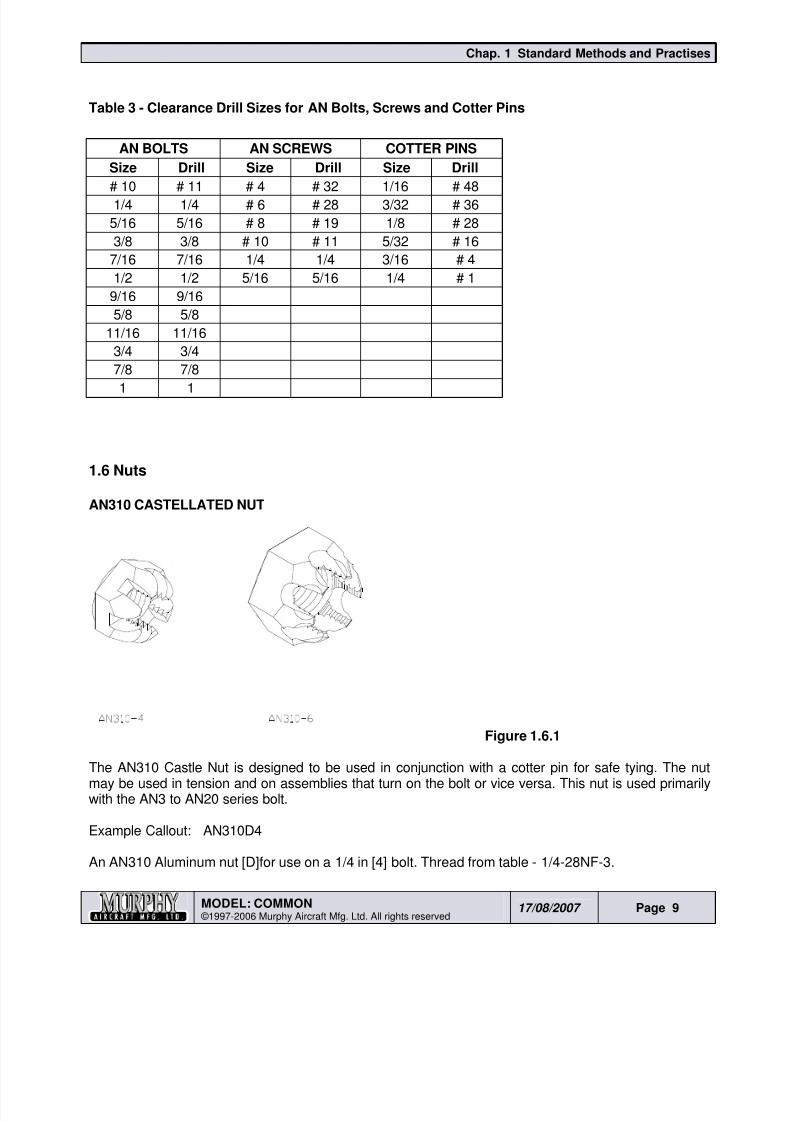
Table 1 - Bolts............................................................................................................................7 Table 2 - Screws ........................................................................................................................ 8 Table 3 - Clearance Drill Sizes for AN Bolts, Screws and Cotter Pins.......................................9
1.6 Nuts............................................................................................................................................9
AN310 CASTELLATED NUT..................................................................................................... 9 AN315 PLAIN NUT .................................................................................................................. 10 AN316 CHECK NUT ................................................................................................................ 10 AN365 SELF-LOCKING FIBRENUT........................................................................................11
1.7 Washers...................................................................................................................................11
1.8 Plastic Coating........................................................................................................................12
1.9 Layouts....................................................................................................................................12
1.10 Deburring ..............................................................................................................................12
1.11 Edges.....................................................................................................................................13
1.12 Inside Corners and Bend Radii ...........................................................................................13
1.13 Edge Distance.......................................................................................................................15
1.14 Riveting ................................................................................................................................. 15
Rivet Chart ...............................................................................................................................16
1.15 Aircraft Solid-Shank Rivets ................................................................................................. 17
1.16 Riveting Solid Shank............................................................................................................17
Rivet Pitch................................................................................................................................17
1.17 Bucking Bars ........................................................................................................................ 20
1.18 Rivet Codes and Identification............................................................................................21
1.19 Rivet Head Styles ................................................................................................................. 22
8/19/2019 Ch01 Standard Methods and Practises
http://slidepdf.com/reader/full/ch01-standard-methods-and-practises 2/44
Chap. 1 Standard Methods and Practises
MODEL: COMMON ©1997-2006 Murphy Aircraft Mfg. Ltd. All rights reserved
17/08/2007 Page 2
1.20 Universal Head Rivets..........................................................................................................23
1.21 Countersunk Rivets .............................................................................................................23
1.22 Dimpling ................................................................................................................................24
1.23 Inspection of a Rivet Joint...................................................................................................25
1.24 Fiberglass Construction ...................................................................................................... 27
1.25 Making Gussets....................................................................................................................28
1.26 Using Sealant........................................................................................................................30
1.27 Do’s and Don’ts in Handling Aluminum Sheets................................................................ 30
1.28 Cable Rigging ....................................................................................................................... 32
1.29 Push Pull Tube Fabrication ................................................................................................. 33
1.30 Reamers ................................................................................................................................34
1.31 Metal Working Glossary of Terms ...................................................................................... 35
1.32 Turnbuckle Assemblies ....................................................................................................... 36
1.33 Safety Methods for Turnbuckles.........................................................................................36
Double Wrap Method...............................................................................................................37
Swaged terminal method ......................................................................................................... 37
1.34 Nut Plates (Floating Anchor Nuts)......................................................................................38
Installing Nut Plates ................................................................................................................. 38
1.35 Some Final Thoughts...........................................................................................................39
1.36 Work Table Construction.....................................................................................................40
Material requirements ..............................................................................................................40
Throughout this manual various styles of “bullets” will be used to convey information, as a general rule
they will be used as follows:- Advisory information.
• Lists of facts to be adhered to, factual information or consequences.
1) Methods or processes to be followed.
a. Sequence of steps within the Methods or Processes to be followed.
8/19/2019 Ch01 Standard Methods and Practises
http://slidepdf.com/reader/full/ch01-standard-methods-and-practises 3/44
Chap. 1 Standard Methods and Practises
MODEL: COMMON ©1997-2006 Murphy Aircraft Mfg. Ltd. All rights reserved
17/08/2007 Page 3
Please read the following information carefully, you will need to refer to it often throughout thebuilding process. It contains information on corrosion protection, drilling, deburring, gussetbuilding etc. Also included is a section on bolt and rivet selection to assist you in areas of themanual where bolt or rivet sizes have not been indicated.
1.1 Metal Surface Preparation
As a protective measure against corrosion, mating metal surfaces should be fully deburred,cleaned with Acetone, and then coated liberally with primer. This provides a seal between thesurfaces to prevent corrosion and moisture ingress. It is a good practice to coat the end of therivet on the inside surface after installation.
As an optional measure, the rivets can be dipped in primer prior to installation. This providesprotection inside the hole and seals out moisture, be careful to avoid getting excess chromateon the exterior surfaces.
Epoxy primer must be mixed in accordance with the manufacturers directions as displayed on
the containers. It is advisable to mix only the amount required at the time in a small containerfor immediate use. However, it is possible to mix larger amounts for reuse but these must bekept in a sealed container and stored in a freezer or refrigerator.
1.2 Drilling Holes
It is good practice to only use a #40 drill to make pilot holes when doing any assembly work. Ifpossible never drill to final hole size until assembly is complete and you are confident to do so.This allows for any movement between parts or adjustment you may need to make which could
cause misalignment of the holes during final assembly.
Always use a sharp drill bit as:
• A sharp bit will not wander as easily as a dull one.
• You can drill faster with a sharp bit.
• You don’t have to push as hard, risking bending flanges etc.
Always be careful to drill square to the work surface.
Always make sure when drilling through multiple parts or layers that they are clamped togethertightly and there is no movement during drilling.
Always deburr holes on both sides of each part before final assembly.
Always keep work surfaces clean and free from swarf which can scratch and damage panels.
8/19/2019 Ch01 Standard Methods and Practises
http://slidepdf.com/reader/full/ch01-standard-methods-and-practises 4/44
Chap. 1 Standard Methods and Practises
MODEL: COMMON ©1997-2006 Murphy Aircraft Mfg. Ltd. All rights reserved
17/08/2007 Page 4
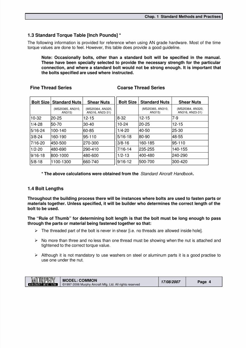
1.3 Standard Torque Table [Inch Pounds] *
The following information is provided for reference when using AN grade hardware. Most of the timetorque values are done to feel. However, this table does provide a good guideline.
Note: Occasionally bolts, other than a standard bolt will be specified in the manual.These have been specially selected to provide the necessary strength for the particularconnection, and where a standard bolt would not be strong enough. It is important thatthe bolts specified are used where instructed.
Fine Thread Series Coarse Thread Series
* The above calculations were obtained from the Standard Aircraft Handbook .
1.4 Bolt Lengths
Throughout the building process there will be instances where bolts are used to fasten parts ormaterials together. Unless specified, it will be builder who determines the correct length of thebolt to be used.
The “Rule of Thumb” for determining bolt length is that the bolt must be long enough to passthrough the parts or material being fastened together so that:
The threaded part of the bolt is never in shear [i.e. no threads are allowed inside hole].
No more than three and no less than one thread must be showing when the nut is attached andtightened to the correct torque value.
Although it is not mandatory to use washers on steel or aluminum parts it is a good practise touse one under the nut.
Bolt Size Standard Nuts Shear Nuts
(MS20365, AN310,AN315)
(MS20364, AN320,AN316, AN23-31)
10-32 20-25 12-151/4-28 50-70 30-40
5/16-24 100-140 60-85
3/8-24 160-190 95-110
7/16-20 450-500 270-300
1/2-20 480-690 290-410
9/16-18 800-1000 480-600
5/8-18 1100-1300 660-740
Bolt Size Standard Nuts Shear Nuts
(MS20365, AN310,AN315)
(MS20364, AN320,AN316, AN23-31)
8-32 12-15 7-910-24 20-25 12-15
1/4-20 40-50 25-30
5/16-18 80-90 48-55
3/8-16 160-185 95-110
7/16-14 235-255 140-155
1/2-13 400-480 240-290
9/16-12 500-700 300-420

8/19/2019 Ch01 Standard Methods and Practises
http://slidepdf.com/reader/full/ch01-standard-methods-and-practises 5/44
Chap. 1 Standard Methods and Practises
MODEL: COMMON ©1997-2006 Murphy Aircraft Mfg. Ltd. All rights reserved
17/08/2007 Page 5
More precise determinations of Grip Length are found in a number of books including theStandard Aircraft Worker’s Manual.
8/19/2019 Ch01 Standard Methods and Practises
http://slidepdf.com/reader/full/ch01-standard-methods-and-practises 6/44
Chap. 1 Standard Methods and Practises
MODEL: COMMON ©1997-2006 Murphy Aircraft Mfg. Ltd. All rights reserved
17/08/2007 Page 6
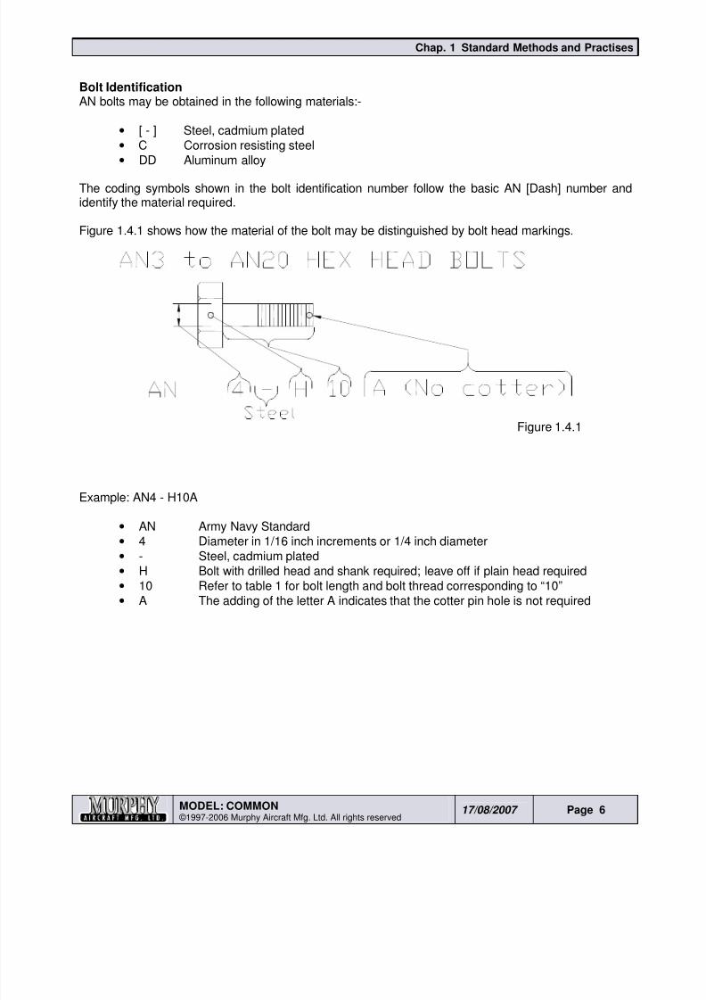
Bolt IdentificationAN bolts may be obtained in the following materials:-
• [ - ] Steel, cadmium plated
• C Corrosion resisting steel
• DD Aluminum alloy
The coding symbols shown in the bolt identification number follow the basic AN [Dash] number andidentify the material required.
Figure 1.4.1 shows how the material of the bolt may be distinguished by bolt head markings.
Figure 1.4.1
Example: AN4 - H10A
• AN Army Navy Standard
• 4 Diameter in 1/16 inch increments or 1/4 inch diameter
• - Steel, cadmium plated
• H Bolt with drilled head and shank required; leave off if plain head required
• 10 Refer to table 1 for bolt length and bolt thread corresponding to “10”
• A The adding of the letter A indicates that the cotter pin hole is not required
8/19/2019 Ch01 Standard Methods and Practises
http://slidepdf.com/reader/full/ch01-standard-methods-and-practises 7/44
Chap. 1 Standard Methods and Practises
MODEL: COMMON ©1997-2006 Murphy Aircraft Mfg. Ltd. All rights reserved
17/08/2007 Page 7
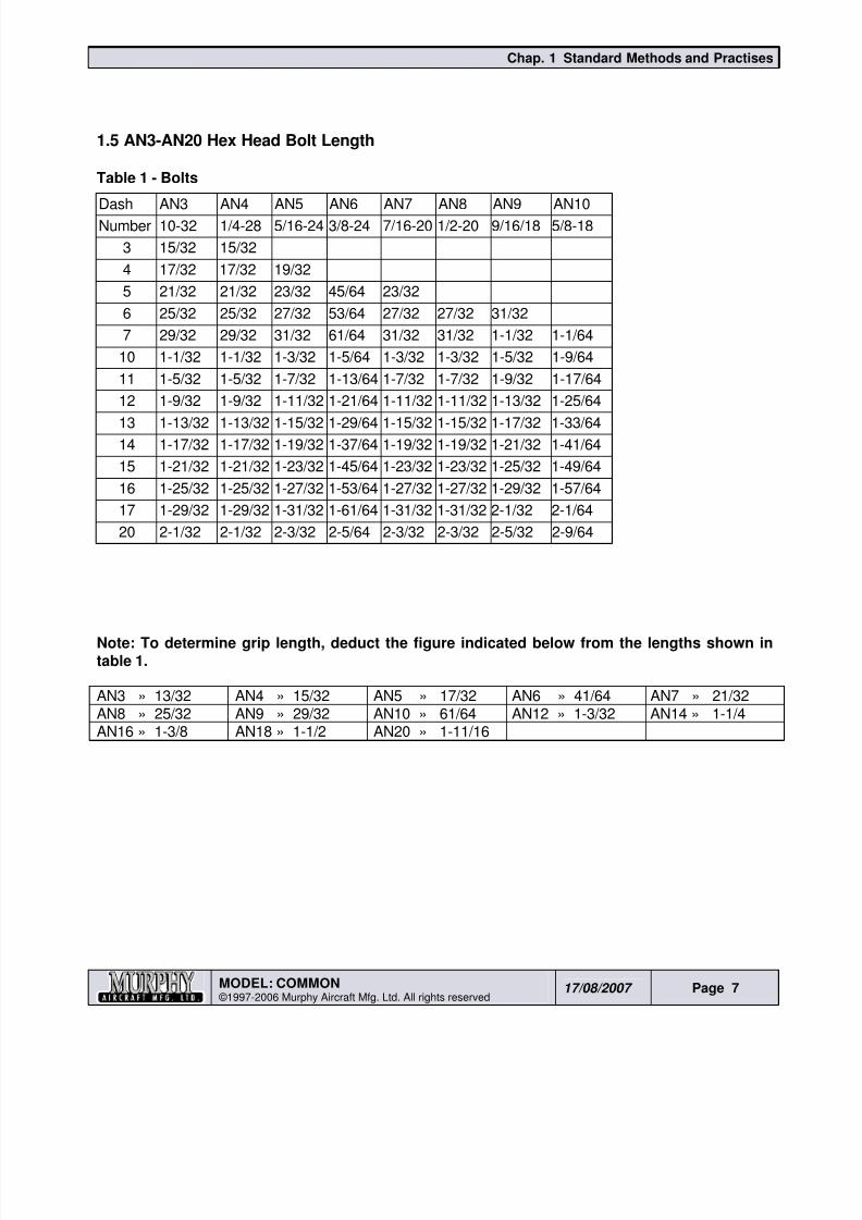
1.5 AN3-AN20 Hex Head Bolt Length
Table 1 - Bolts
Dash AN3 AN4 AN5 AN6 AN7 AN8 AN9 AN10Number 10-32 1/4-28 5/16-24 3/8-24 7/16-20 1/2-20 9/16/18 5/8-18
3 15/32 15/32
4 17/32 17/32 19/32
5 21/32 21/32 23/32 45/64 23/32
6 25/32 25/32 27/32 53/64 27/32 27/32 31/32
7 29/32 29/32 31/32 61/64 31/32 31/32 1-1/32 1-1/64
10 1-1/32 1-1/32 1-3/32 1-5/64 1-3/32 1-3/32 1-5/32 1-9/64
11 1-5/32 1-5/32 1-7/32 1-13/64 1-7/32 1-7/32 1-9/32 1-17/64
12 1-9/32 1-9/32 1-11/32 1-21/64 1-11/32 1-11/32 1-13/32 1-25/64
13 1-13/32 1-13/32 1-15/32 1-29/64 1-15/32 1-15/32 1-17/32 1-33/64
14 1-17/32 1-17/32 1-19/32 1-37/64 1-19/32 1-19/32 1-21/32 1-41/64
15 1-21/32 1-21/32 1-23/32 1-45/64 1-23/32 1-23/32 1-25/32 1-49/64
16 1-25/32 1-25/32 1-27/32 1-53/64 1-27/32 1-27/32 1-29/32 1-57/64
17 1-29/32 1-29/32 1-31/32 1-61/64 1-31/32 1-31/32 2-1/32 2-1/64
20 2-1/32 2-1/32 2-3/32 2-5/64 2-3/32 2-3/32 2-5/32 2-9/64
Note: To determine grip length, deduct the figure indicated below from the lengths shown intable 1.
AN3 » 13/32 AN4 » 15/32 AN5 » 17/32 AN6 » 41/64 AN7 » 21/32AN8 » 25/32 AN9 » 29/32 AN10 » 61/64 AN12 » 1-3/32 AN14 » 1-1/4AN16 » 1-3/8 AN18 » 1-1/2 AN20 » 1-11/16
8/19/2019 Ch01 Standard Methods and Practises
http://slidepdf.com/reader/full/ch01-standard-methods-and-practises 8/44
Chap. 1 Standard Methods and Practises
MODEL: COMMON ©1997-2006 Murphy Aircraft Mfg. Ltd. All rights reserved
17/08/2007 Page 8
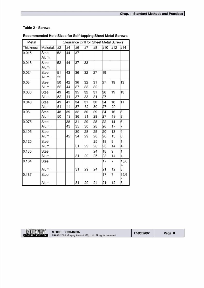
Table 2 - Screws
Recommended Hole Sizes for Self-tapping Sheet Metal Screws
Metal Clearance Drill for Sheet Metal Screws
Thickness Material. #2 #4 #6 #7 #8 #10 #12 #140.015 Steel 52 44 37
Alum.
0.018 Steel 52 44 37 33
Alum.
0.024 Steel 51 43 36 32 27 19
Alum. 52
0.03 Steel 50 42 36 32 31 27 19 13
Alum. 52 44 37 33 32
0.036 Steel 49 42 35 32 31 26 19 13
Alum. 52 44 37 33 31 270.048 Steel 49 41 34 31 30 24 18 11
Alum. 51 44 37 32 30 27 20
0.06 Steel 48 39 32 30 29 24 16 8
Alum. 50 43 36 31 29 27 19 8
0.075 Steel 38 31 29 28 22 14 6
Alum. 43 35 30 28 26 17 7
0.105 Steel 30 28 25 20 13 4
Alum. 42 34 29 26 26 15 6
0.125 Steel 25 18 9 1
Alum. 31 29 26 23 14 40.135 Steel 24 18 9 1
Alum. 31 29 25 23 14 4
0.164 Steel 17 7 15/64
Alum. 31 29 24 21 12 3
0.187 Steel 17 7 15/64
Alum. 31 29 24 21 12 3
8/19/2019 Ch01 Standard Methods and Practises
http://slidepdf.com/reader/full/ch01-standard-methods-and-practises 9/44
8/19/2019 Ch01 Standard Methods and Practises
http://slidepdf.com/reader/full/ch01-standard-methods-and-practises 10/44
Chap. 1 Standard Methods and Practises
MODEL: COMMON ©1997-2006 Murphy Aircraft Mfg. Ltd. All rights reserved
17/08/2007 Page 10
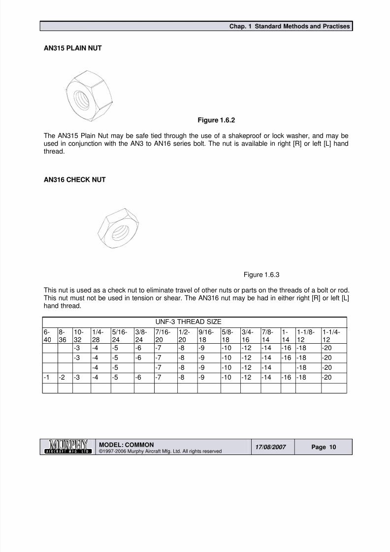
AN315 PLAIN NUT
Figure 1.6.2
The AN315 Plain Nut may be safe tied through the use of a shakeproof or lock washer, and may beused in conjunction with the AN3 to AN16 series bolt. The nut is available in right [R] or left [L] handthread.
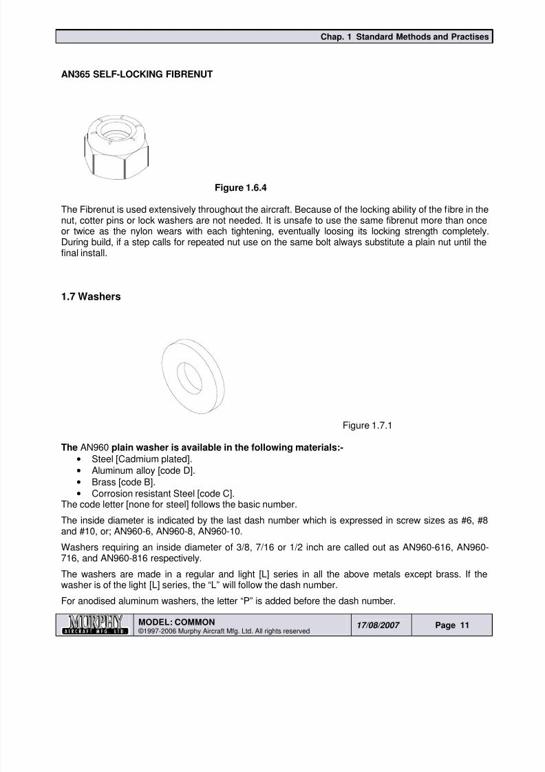
AN316 CHECK NUT
Figure 1.6.3
This nut is used as a check nut to eliminate travel of other nuts or parts on the threads of a bolt or rod.This nut must not be used in tension or shear. The AN316 nut may be had in either right [R] or left [L]hand thread.
UNF-3 THREAD SIZE
6-40
8-36
10-32
1/4-28
5/16-24
3/8-24
7/16-20
1/2-20
9/16-18
5/8-18
3/4-16
7/8-14
1-14
1-1/8-12
1-1/4-12
-3 -4 -5 -6 -7 -8 -9 -10 -12 -14 -16 -18 -20
-3 -4 -5 -6 -7 -8 -9 -10 -12 -14 -16 -18 -20
-4 -5 -7 -8 -9 -10 -12 -14 -18 -20
-1 -2 -3 -4 -5 -6 -7 -8 -9 -10 -12 -14 -16 -18 -20
8/19/2019 Ch01 Standard Methods and Practises
http://slidepdf.com/reader/full/ch01-standard-methods-and-practises 11/44
Chap. 1 Standard Methods and Practises
MODEL: COMMON ©1997-2006 Murphy Aircraft Mfg. Ltd. All rights reserved
17/08/2007 Page 11
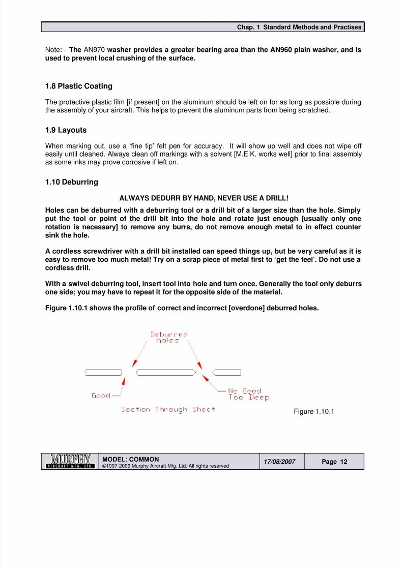
AN365 SELF-LOCKING FIBRENUT
Figure 1.6.4
The Fibrenut is used extensively throughout the aircraft. Because of the locking ability of the fibre in thenut, cotter pins or lock washers are not needed. It is unsafe to use the same fibrenut more than onceor twice as the nylon wears with each tightening, eventually loosing its locking strength completely.During build, if a step calls for repeated nut use on the same bolt always substitute a plain nut until thefinal install.
1.7 Washers
Figure 1.7.1
The AN960 plain washer is available in the following materials:-
• Steel [Cadmium plated].
• Aluminum alloy [code D].
• Brass [code B].
• Corrosion resistant Steel [code C].The code letter [none for steel] follows the basic number.
The inside diameter is indicated by the last dash number which is expressed in screw sizes as #6, #8and #10, or; AN960-6, AN960-8, AN960-10.
Washers requiring an inside diameter of 3/8, 7/16 or 1/2 inch are called out as AN960-616, AN960-716, and AN960-816 respectively.
The washers are made in a regular and light [L] series in all the above metals except brass. If thewasher is of the light [L] series, the “L” will follow the dash number.
For anodised aluminum washers, the letter “P” is added before the dash number.
8/19/2019 Ch01 Standard Methods and Practises
http://slidepdf.com/reader/full/ch01-standard-methods-and-practises 12/44
Chap. 1 Standard Methods and Practises
MODEL: COMMON ©1997-2006 Murphy Aircraft Mfg. Ltd. All rights reserved
17/08/2007 Page 12
Note: - The AN970 washer provides a greater bearing area than the AN960 plain washer, and isused to prevent local crushing of the surface.
1.8 Plastic Coating
The protective plastic film [if present] on the aluminum should be left on for as long as possible duringthe assembly of your aircraft. This helps to prevent the aluminum parts from being scratched.
1.9 Layouts
When marking out, use a ‘fine tip’ felt pen for accuracy. It will show up well and does not wipe offeasily until cleaned. Always clean off markings with a solvent [M.E.K. works well] prior to final assemblyas some inks may prove corrosive if left on.
1.10 Deburring
ALWAYS DEDURR BY HAND, NEVER USE A DRILL!
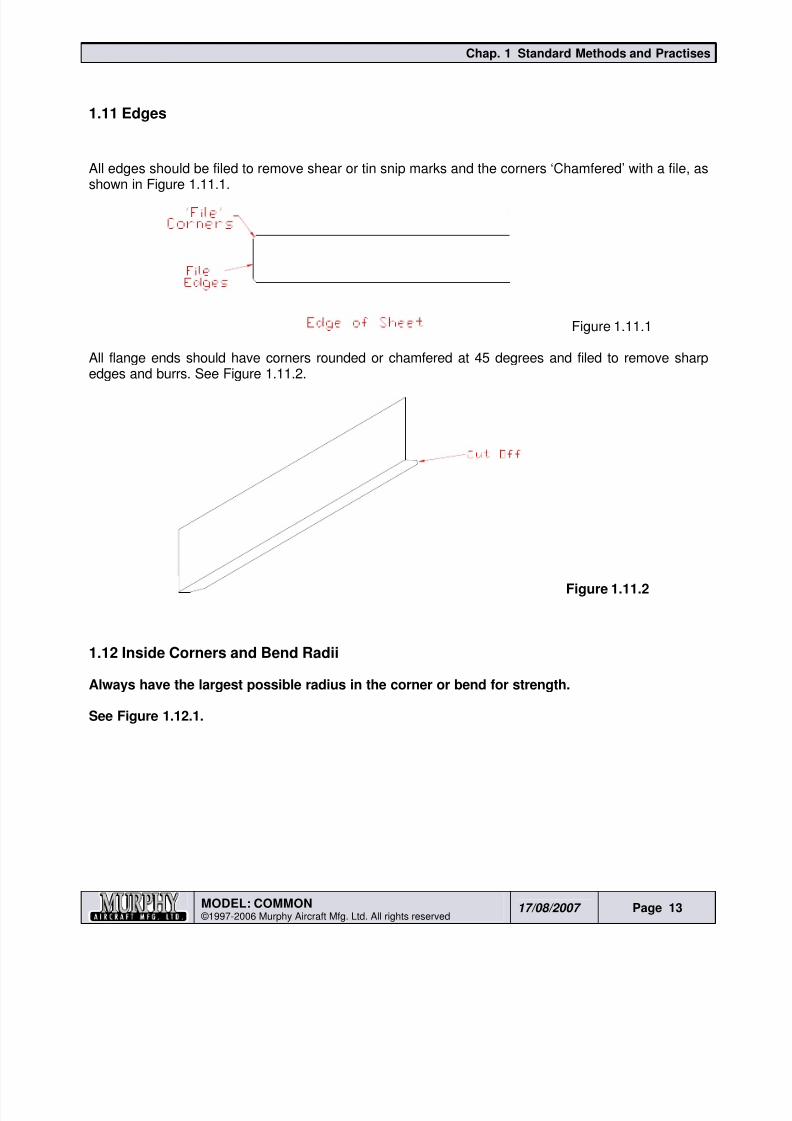
Holes can be deburred with a deburring tool or a drill bit of a larger size than the hole. Simplyput the tool or point of the drill bit into the hole and rotate just enough [usually only onerotation is necessary] to remove any burrs, do not remove enough metal to in effect countersink the hole.
A cordless screwdriver with a drill bit installed can speed things up, but be very careful as it iseasy to remove too much metal! Try on a scrap piece of metal first to ‘get the feel’. Do not use acordless drill.
With a swivel deburring tool, insert tool into hole and turn once. Generally the tool only deburrsone side; you may have to repeat it for the opposite side of the material.
Figure 1.10.1 shows the profile of correct and incorrect [overdone] deburred holes.
Figure 1.10.1
8/19/2019 Ch01 Standard Methods and Practises
http://slidepdf.com/reader/full/ch01-standard-methods-and-practises 13/44
Chap. 1 Standard Methods and Practises
MODEL: COMMON ©1997-2006 Murphy Aircraft Mfg. Ltd. All rights reserved
17/08/2007 Page 13
1.11 Edges
All edges should be filed to remove shear or tin snip marks and the corners ‘Chamfered’ with a file, as
shown in Figure 1.11.1.
Figure 1.11.1
All flange ends should have corners rounded or chamfered at 45 degrees and filed to remove sharp
edges and burrs. See Figure 1.11.2.
Figure 1.11.2
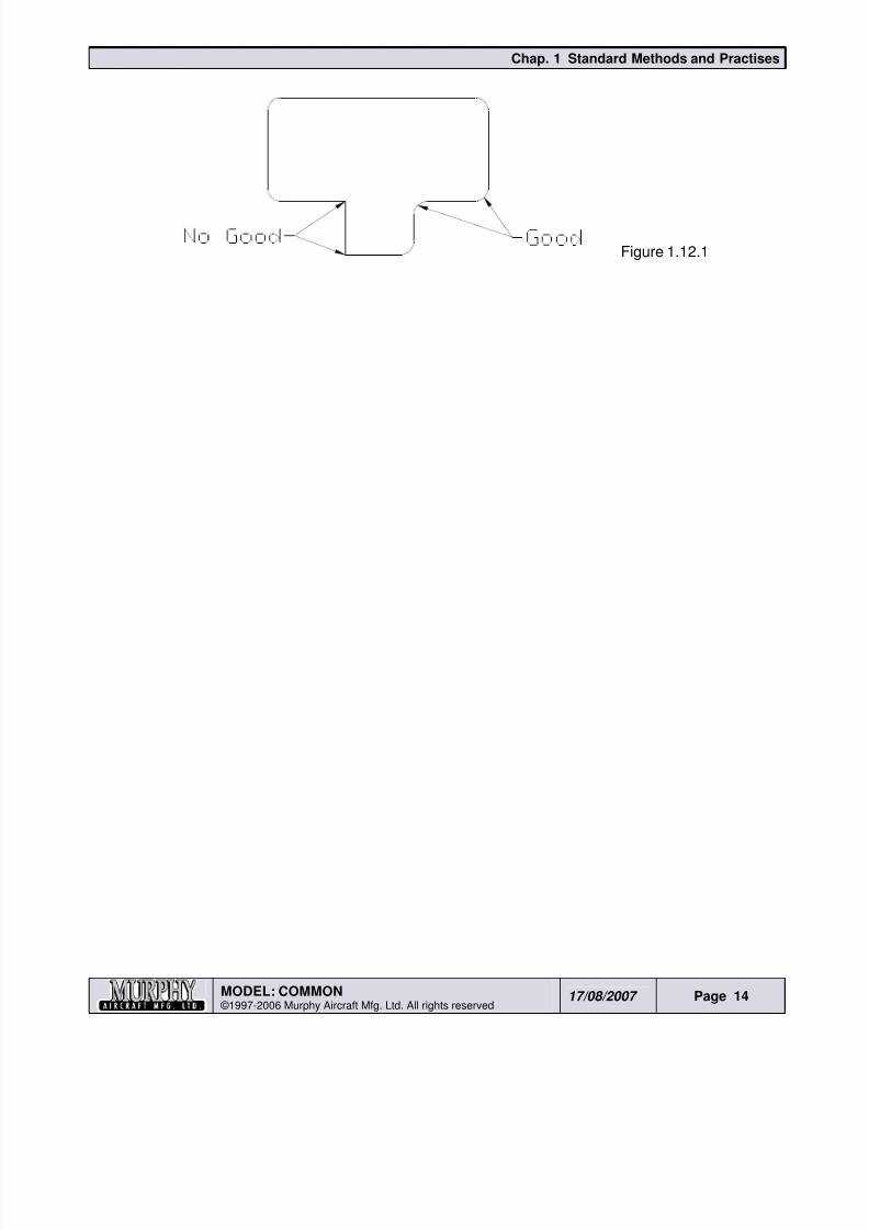
1.12 Inside Corners and Bend Radii
Always have the largest possible radius in the corner or bend for strength.
See Figure 1.12.1.
8/19/2019 Ch01 Standard Methods and Practises
http://slidepdf.com/reader/full/ch01-standard-methods-and-practises 14/44
Chap. 1 Standard Methods and Practises
MODEL: COMMON ©1997-2006 Murphy Aircraft Mfg. Ltd. All rights reserved
17/08/2007 Page 14
Figure 1.12.1
8/19/2019 Ch01 Standard Methods and Practises
http://slidepdf.com/reader/full/ch01-standard-methods-and-practises 15/44
Chap. 1 Standard Methods and Practises
MODEL: COMMON ©1997-2006 Murphy Aircraft Mfg. Ltd. All rights reserved
17/08/2007 Page 15
1.13 Edge Distance
Edge distance is simply the distance from the center of the rivet or bolt hole to the edge of the skin,flange or fitting. The proper edge distance is required to ensure that the rivets or bolts are not rippedfrom their location because of inadequate shear strength.
The ‘rule of thumb’ is that the edge distance from center line of the hole to edge of material shouldalways equal twice the rivet/bolt diameter.
At Murphy Aircraft we normally allow and additional 1/16” allowance in case we need to drill to the nextsize or trim material back. To go any greater dimension than this does not increase the strength, it justadds extra weight and can be unsightly.
A circle template will assist you in laying out edge distance, they are cheap and easily obtainableat most office or school supply store.
Always make sure that you have adequate edge distance on your parts.
Rule of thumb for edge distance is: Rivet or bolt diameter X 2
i.e. 1/8” rivet X 2 = 1/4” edge distance
or 3/16” bolt X 2 = 3/8” edge distance
Avoid more than 2 1/2 times edge distance
1.14 Riveting
The standard rivet used in all Murphy aircraft is the Avex rivet. Many people mistakenly refer to themas pop rivets. “Pop” is a brand name. The correct terminology is blind rivet which simply means it canbe used from one side only. There are considerable differences between the Avex rivet and the morecommon pop rivet.
Never substitute a pop type rivet for the Avex rivets.
In the kit there are three diameters of rivets, 1/8”, 5/32” and 3/16”. They come in variouslengths. There are also two head styles, countersunk and domed. In addition, there are twomaterials, aluminum and stainless steel. The stainless steel rivets are used in a few locations,normally in high shear application. In your kit you will also find a number of large head allaluminum rivets. These rivets are non-structural and are used in installing the windows.
Always check carefully with the instructions to ensure you use the correct diameter, lengths, headsand material of rivet for the various locations and applications.
Always check that you are using the proper grip length rivet for the job you are doing.
i.e. 1/8” X 1/8” rivet [refers to diameter x grip length] will secure only up to 1/8” ofmaterial thickness, just as a 1/4” grip length rivet will secure only up to 1/4” of material.
Make sure the rivet is all the way into the hole and that the parts being riveted have not pulled awayfrom each other or separated.
Keep rivet gun square to the work when pulling rivets.
8/19/2019 Ch01 Standard Methods and Practises
http://slidepdf.com/reader/full/ch01-standard-methods-and-practises 16/44
Chap. 1 Standard Methods and Practises
MODEL: COMMON ©1997-2006 Murphy Aircraft Mfg. Ltd. All rights reserved
17/08/2007 Page 16
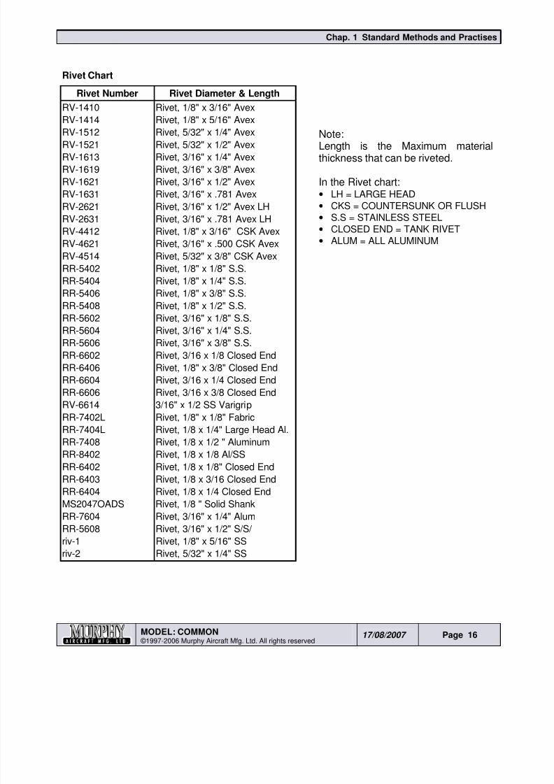
Rivet Chart
Rivet Number Rivet Diameter & Length
RV-1410 Rivet, 1/8" x 3/16" Avex
RV-1414 Rivet, 1/8" x 5/16" Avex
RV-1512 Rivet, 5/32" x 1/4" AvexRV-1521 Rivet, 5/32" x 1/2" Avex
RV-1613 Rivet, 3/16" x 1/4" Avex
RV-1619 Rivet, 3/16" x 3/8" Avex
RV-1621 Rivet, 3/16" x 1/2" Avex
RV-1631 Rivet, 3/16" x .781 Avex
RV-2621 Rivet, 3/16" x 1/2" Avex LH
RV-2631 Rivet, 3/16" x .781 Avex LH
RV-4412 Rivet, 1/8" x 3/16" CSK Avex
RV-4621 Rivet, 3/16" x .500 CSK Avex
RV-4514 Rivet, 5/32" x 3/8" CSK Avex
RR-5402 Rivet, 1/8" x 1/8" S.S.
RR-5404 Rivet, 1/8" x 1/4" S.S.
RR-5406 Rivet, 1/8" x 3/8" S.S.
RR-5408 Rivet, 1/8" x 1/2" S.S.
RR-5602 Rivet, 3/16" x 1/8" S.S.
RR-5604 Rivet, 3/16" x 1/4" S.S.
RR-5606 Rivet, 3/16" x 3/8" S.S.
RR-6602 Rivet, 3/16 x 1/8 Closed End
RR-6406 Rivet, 1/8" x 3/8" Closed End
RR-6604 Rivet, 3/16 x 1/4 Closed End
RR-6606 Rivet, 3/16 x 3/8 Closed EndRV-6614 3/16" x 1/2 SS Varigrip
RR-7402L Rivet, 1/8" x 1/8" Fabric
RR-7404L Rivet, 1/8 x 1/4" Large Head Al.
RR-7408 Rivet, 1/8 x 1/2 " Aluminum
RR-8402 Rivet, 1/8 x 1/8 Al/SS
RR-6402 Rivet, 1/8 x 1/8" Closed End
RR-6403 Rivet, 1/8 x 3/16 Closed End
RR-6404 Rivet, 1/8 x 1/4 Closed End
MS2047OADS Rivet, 1/8 " Solid Shank
RR-7604 Rivet, 3/16" x 1/4" Alum
RR-5608 Rivet, 3/16" x 1/2" S/S/riv-1 Rivet, 1/8" x 5/16" SS
riv-2 Rivet, 5/32" x 1/4" SS
Note:Length is the Maximum materialthickness that can be riveted.
In the Rivet chart:• LH = LARGE HEAD
• CKS = COUNTERSUNK OR FLUSH
• S.S = STAINLESS STEEL
• CLOSED END = TANK RIVET
• ALUM = ALL ALUMINUM
8/19/2019 Ch01 Standard Methods and Practises
http://slidepdf.com/reader/full/ch01-standard-methods-and-practises 17/44
Chap. 1 Standard Methods and Practises
MODEL: COMMON ©1997-2006 Murphy Aircraft Mfg. Ltd. All rights reserved
17/08/2007 Page 17
1.15 Aircraft Solid-Shank Rivets
The solid-shank rivet increases in girth and strength when properly installed. A steel bolt will actuallydecrease in diameter when it is installed and torqued. Some manufacturers of special fastenersattempt to duplicate the natural action of solid-shank rivets by putting expanding sections on the
fasteners’ pulling stems. Most of these special fasteners only approximate the natural shank expansionof a driven solid-shank rivet.
Since pure aluminum weighs one-third as much as steel, aluminum alloy solid-shank rivets arelighter than many other fasteners. Their lightness is an advantage, but it limits their usefulness:Solid-shank rivets greater than 1/2 inch in diameter are not used. However, the allowable range,between 3/32” and 1/2” in diameter, offers enough variety for the needs of most typical aircraftconstruction or repairs.
1.16 Riveting Solid Shank
Riveting is sometimes referred to as a “mushrooming” process. When the rivet is being driven certainphysical changes take place; the rivet diameter cross-sectional area increases, the manufactured headexpands, the shank expands to the size of the hole, and the hardness of the rivet increases due to thecold working action changing its temper designation from T4 to T3
There are three steps involved in planning and executing a solid-shank rivet joint for structural repair,layout, installation, and inspection.
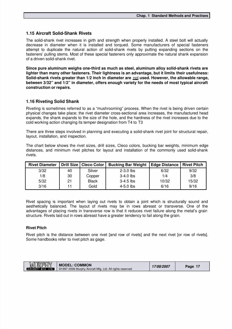
The chart below shows the rivet sizes, drill sizes, Cleco colors, bucking bar weights, minimum edgedistances, and minimum rivet pitches for layout and installation of the commonly used solid-shankrivets.
Rivet Diameter Drill Size Cleco Color Bucking Bar Weight Edge Distance Rivet Pitch3/32 40 Silver 2-3.0 lbs 6/32 9/32
1/8 30 Copper 3-4.0 lbs 1/4 3/8
5/32 21 Black 3-4.5 lbs 10/32 15/32
3/16 11 Gold 4-5.0 lbs 6/16 9/16
Rivet spacing is important when laying out rivets to obtain a joint which is structurally sound andaesthetically balanced. The layout of rivets may be in rows abreast or transverse. One of theadvantages of placing rivets in transverse row is that it reduces rivet failure along the metal’s grainstructure. Rivets laid out in rows abreast have a greater tendency to fail along the grain.
Rivet Pitch
Rivet pitch is the distance between one rivet [and row of rivets] and the next rivet [or row of rivets].Some handbooks refer to rivet pitch as gage.
8/19/2019 Ch01 Standard Methods and Practises
http://slidepdf.com/reader/full/ch01-standard-methods-and-practises 18/44
Chap. 1 Standard Methods and Practises
MODEL: COMMON ©1997-2006 Murphy Aircraft Mfg. Ltd. All rights reserved
17/08/2007 Page 18
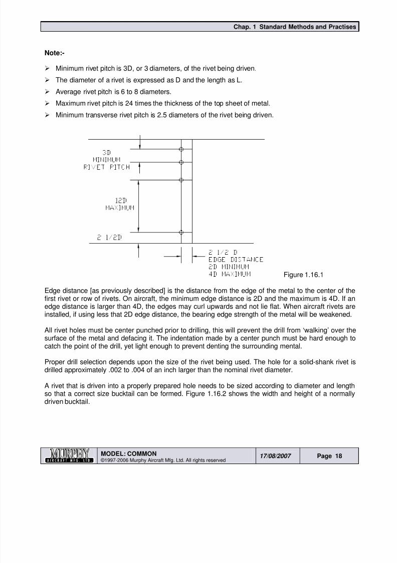
Note:-
Minimum rivet pitch is 3D, or 3 diameters, of the rivet being driven.
The diameter of a rivet is expressed as D and the length as L.
Average rivet pitch is 6 to 8 diameters. Maximum rivet pitch is 24 times the thickness of the top sheet of metal.
Minimum transverse rivet pitch is 2.5 diameters of the rivet being driven.
Figure 1.16.1
Edge distance [as previously described] is the distance from the edge of the metal to the center of thefirst rivet or row of rivets. On aircraft, the minimum edge distance is 2D and the maximum is 4D. If anedge distance is larger than 4D, the edges may curl upwards and not lie flat. When aircraft rivets areinstalled, if using less that 2D edge distance, the bearing edge strength of the metal will be weakened.
All rivet holes must be center punched prior to drilling, this will prevent the drill from ‘walking’ over thesurface of the metal and defacing it. The indentation made by a center punch must be hard enough tocatch the point of the drill, yet light enough to prevent denting the surrounding mental.
Proper drill selection depends upon the size of the rivet being used. The hole for a solid-shank rivet isdrilled approximately .002 to .004 of an inch larger than the nominal rivet diameter.
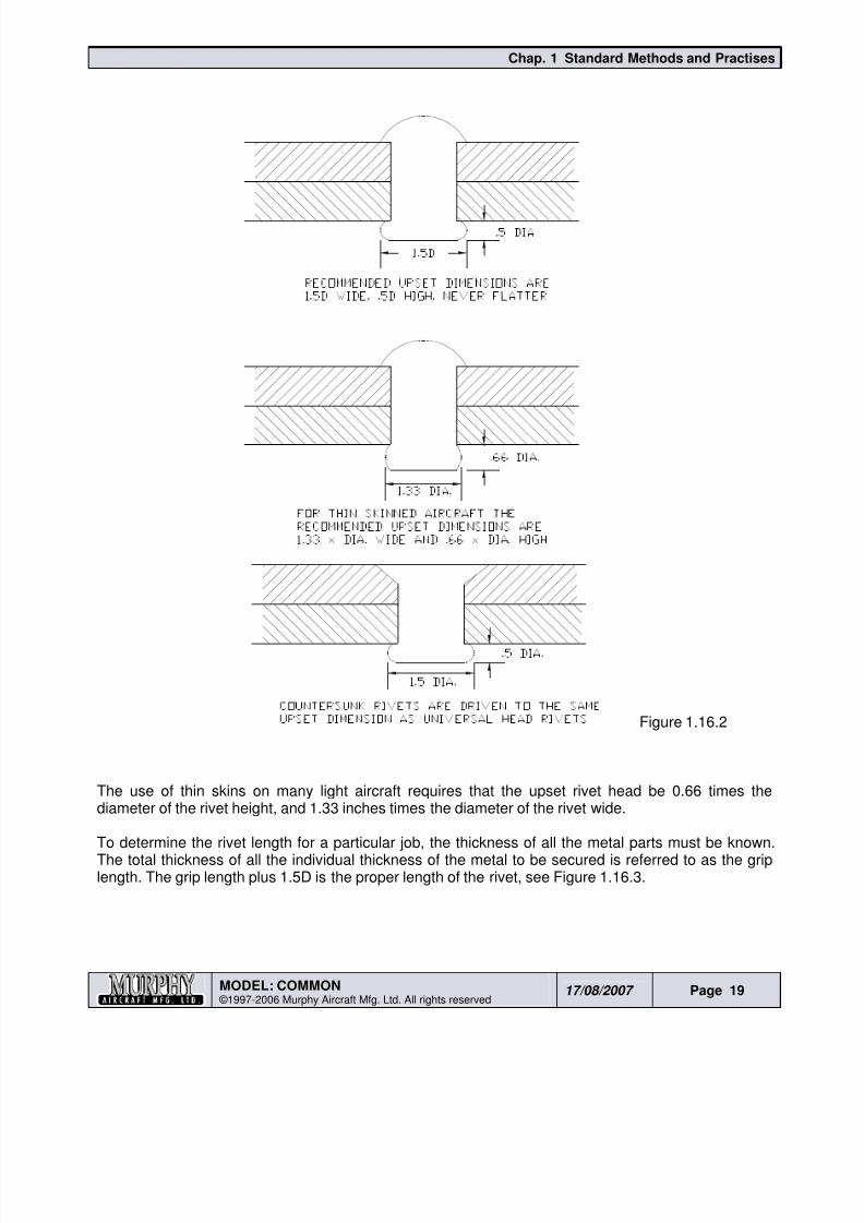
A rivet that is driven into a properly prepared hole needs to be sized according to diameter and lengthso that a correct size bucktail can be formed. Figure 1.16.2 shows the width and height of a normallydriven bucktail.
8/19/2019 Ch01 Standard Methods and Practises
http://slidepdf.com/reader/full/ch01-standard-methods-and-practises 19/44
8/19/2019 Ch01 Standard Methods and Practises
http://slidepdf.com/reader/full/ch01-standard-methods-and-practises 20/44
Chap. 1 Standard Methods and Practises
MODEL: COMMON ©1997-2006 Murphy Aircraft Mfg. Ltd. All rights reserved
17/08/2007 Page 20
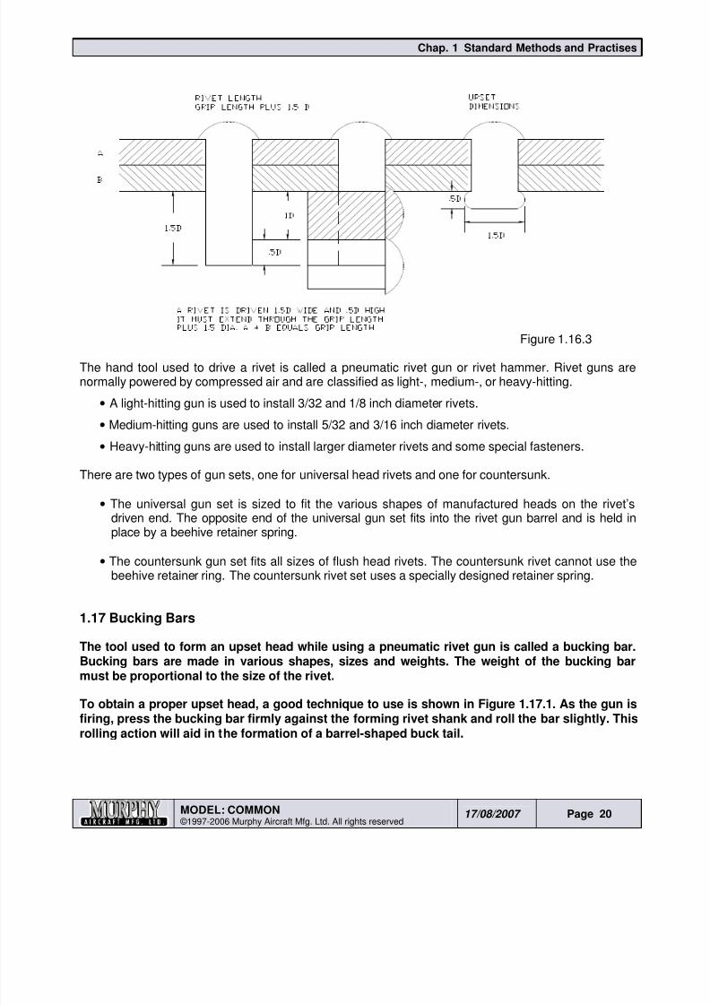
Figure 1.16.3
The hand tool used to drive a rivet is called a pneumatic rivet gun or rivet hammer. Rivet guns arenormally powered by compressed air and are classified as light-, medium-, or heavy-hitting.
• A light-hitting gun is used to install 3/32 and 1/8 inch diameter rivets.
• Medium-hitting guns are used to install 5/32 and 3/16 inch diameter rivets.
• Heavy-hitting guns are used to install larger diameter rivets and some special fasteners.
There are two types of gun sets, one for universal head rivets and one for countersunk.
•
The universal gun set is sized to fit the various shapes of manufactured heads on the rivet’sdriven end. The opposite end of the universal gun set fits into the rivet gun barrel and is held inplace by a beehive retainer spring.
• The countersunk gun set fits all sizes of flush head rivets. The countersunk rivet cannot use thebeehive retainer ring. The countersunk rivet set uses a specially designed retainer spring.
1.17 Bucking Bars
The tool used to form an upset head while using a pneumatic rivet gun is called a bucking bar.Bucking bars are made in various shapes, sizes and weights. The weight of the bucking bar
must be proportional to the size of the rivet.
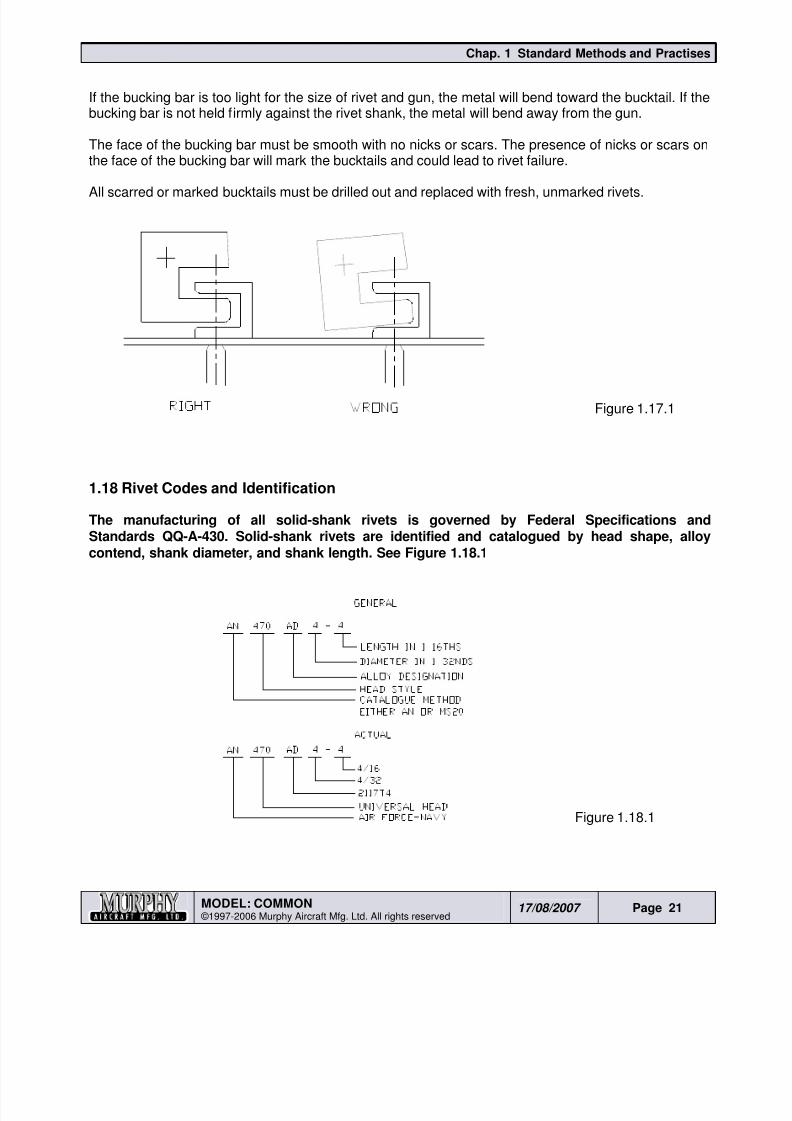
To obtain a proper upset head, a good technique to use is shown in Figure 1.17.1. As the gun isfiring, press the bucking bar firmly against the forming rivet shank and roll the bar slightly. Thisrolling action will aid in the formation of a barrel-shaped buck tail.
8/19/2019 Ch01 Standard Methods and Practises
http://slidepdf.com/reader/full/ch01-standard-methods-and-practises 21/44
Chap. 1 Standard Methods and Practises
MODEL: COMMON ©1997-2006 Murphy Aircraft Mfg. Ltd. All rights reserved
17/08/2007 Page 21
If the bucking bar is too light for the size of rivet and gun, the metal will bend toward the bucktail. If thebucking bar is not held firmly against the rivet shank, the metal will bend away from the gun.
The face of the bucking bar must be smooth with no nicks or scars. The presence of nicks or scars onthe face of the bucking bar will mark the bucktails and could lead to rivet failure.
All scarred or marked bucktails must be drilled out and replaced with fresh, unmarked rivets.
Figure 1.17.1
1.18 Rivet Codes and Identification
The manufacturing of all solid-shank rivets is governed by Federal Specifications andStandards QQ-A-430. Solid-shank rivets are identified and catalogued by head shape, alloycontend, shank diameter, and shank length. See Figure 1.18.1
Figure 1.18.1
8/19/2019 Ch01 Standard Methods and Practises
http://slidepdf.com/reader/full/ch01-standard-methods-and-practises 22/44
Chap. 1 Standard Methods and Practises
MODEL: COMMON ©1997-2006 Murphy Aircraft Mfg. Ltd. All rights reserved
17/08/2007 Page 22
Two shorthand methods of coding are used to identify all aircraft rivets.
For example: - AN470AD4-5, or MS20470AD4-5.
• AN means Air Force-Navy and MS20 means Military Standards 20.
• 470 designate a universal style rivet head.
• AD refers to the alloy 2117T4.
• The hyphenated numbers designate the rivet diameter in thirty-seconds of an inch and the lengthin sixteenths of an inch. Thus, in this example, 4 means 4/32nds-inch diameter, and 5 means5/16ths-inch length.
Although the AN and MS20 methods of cataloguing rivets are similar, it is important to be consistent inwhich of the two methods are used when ordering or identifying rivets. The rivet code is also used inblueprints, drawings, and technical manuals.
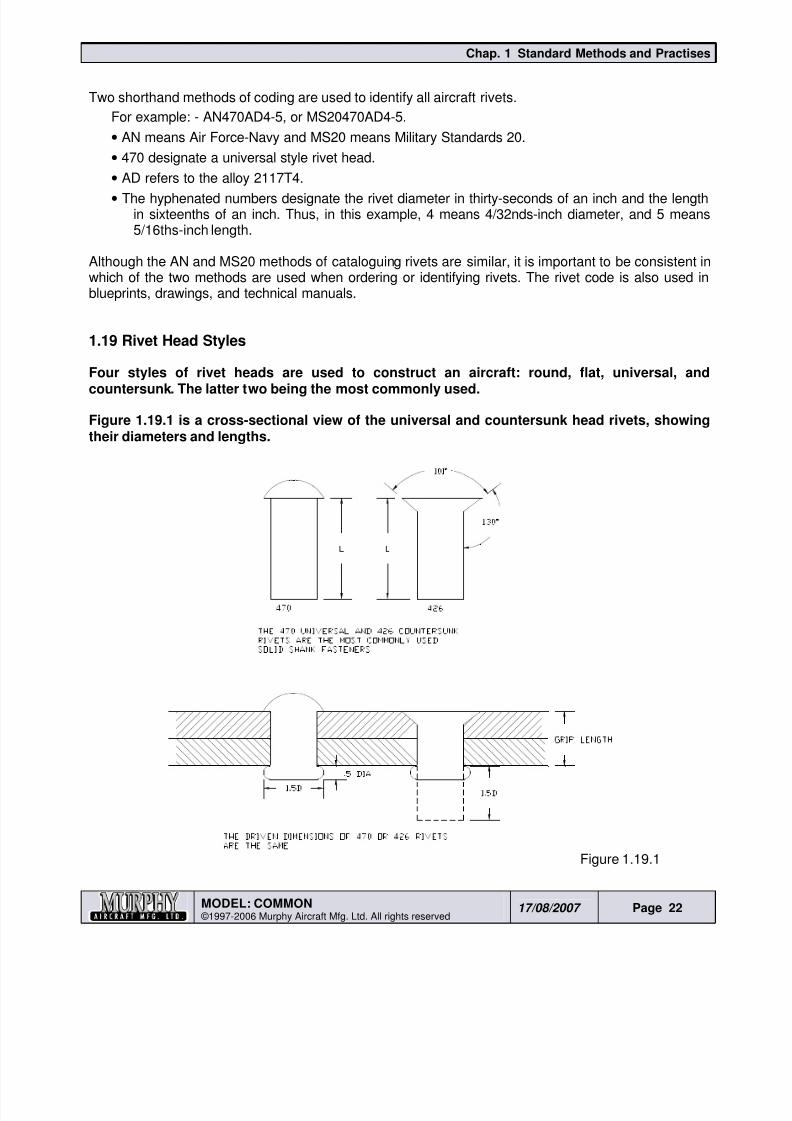
1.19 Rivet Head Styles
Four styles of rivet heads are used to construct an aircraft: round, flat, universal, andcountersunk. The latter two being the most commonly used.
Figure 1.19.1 is a cross-sectional view of the universal and countersunk head rivets, showingtheir diameters and lengths.
Figure 1.19.1
8/19/2019 Ch01 Standard Methods and Practises
http://slidepdf.com/reader/full/ch01-standard-methods-and-practises 23/44
Chap. 1 Standard Methods and Practises
MODEL: COMMON ©1997-2006 Murphy Aircraft Mfg. Ltd. All rights reserved
17/08/2007 Page 23
1.20 Universal Head Rivets
Universal head rivets, also known as protruding head rivets, are used internally in structuralareas and on the skin surfaces of low to medium speed aircraft. A universal head rivet can with
stand a much stronger bearing load than a countersunk rivet because the head is installed flatand binding on the surface of the riveted metal while the countersunk rivet is installed into amachine-tapered well.
The universal head rivet is a combination of several older head styles. When rivets were firstused, various rivet head styles were available. Round head (AN430) rivets were used internallyon high strength structural areas. The flat head (AN442) rivet was used in tight areas where theround head could not be installed. Some modern jet aircraft still use round and flat head rivetsin structural areas.
Aircraft built prior to World War II were low speed aircraft, so a smooth aerodynamic air flowover the wing was not a major concern. As the speed of the aircraft increased, the need forsmaller protruding head rivets accounted for the development of a modified brazier head (456),which causes less drag than larger protruding head rivets. Today, brazier head rivet styles arelikely to be found only on aircraft built before 1955. Because the rivet sets used to drive rivetsother than universals are difficult to obtain today, the older styles can be replaced by universalhead rivets. Advisory Circular 43.14-1 explains the procedure.
1.21 Countersunk Rivets
As aircraft speeds increased, the need for smooth airfoils led to the development of thecountersunk rivet. After experimenting with head angles of 78
o, 90
o and on high-speed jet
fighters, 110o, the aircraft industry adopted a 100o standard. All of these experiments wereattempts to increase the bearing strength of the rivet head around the skin.
The countersunk rivet has to be installed in a depression in such a way as to be flush with thesurface of the skins it is holding together. The depression in the skin is called a nest or a well.The well can be made using a freehand or microstop countersink cutter.
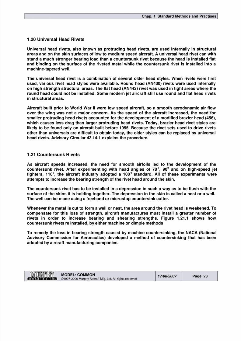
Whenever the metal is cut to form a well or nest, the area around the rivet head is weakened. Tocompensate for this loss of strength, aircraft manufactures must install a greater number ofrivets in order to increase bearing and shearing strengths. Figure 1.21.1 shows howcountersunk rivets re installed, by either machine or dimple methods
To remedy the loss in bearing strength caused by machine countersinking, the NACA (NationalAdvisory Commission for Aeronautics) developed a method of countersinking that has beenadopted by aircraft manufacturing companies.
8/19/2019 Ch01 Standard Methods and Practises
http://slidepdf.com/reader/full/ch01-standard-methods-and-practises 24/44
Chap. 1 Standard Methods and Practises
MODEL: COMMON ©1997-2006 Murphy Aircraft Mfg. Ltd. All rights reserved
17/08/2007 Page 24
Figure 1.21.1
Two different angles may be cut into the top skin, 60o or 82
o. Military aircraft were the first to use the
60o well on some of the older jet fighters. The 82
o well is used when installing wing slugs on the Boeing
747. On some aircraft, a universal is installed from the inside of the wing and driven into an 82o well.
Installing rivets using either the 60o or 82
o NACA countersink method makes them as strong as
universal head rivets. When coldworked, the bucktail formed in the 60o or 82
o angle well is stronger
than the conventional countersink riveting method because the driven head is packed into its well,creating a much stronger head than the regular countersunk rivet can produce.
1.22 Dimpling
Thin skins are never machine countersunk, because the cutter will go completely through thethin skin into the second skin and reduce the bearing strength around the countersunk rivethead. There is an alternative process called ‘dimpling’, which solves this problem.
Dimpling can be done in two ways, cold dimpling or hot dimpling [for thicker aluminum alloys,not discussed in this document]. Cold dimpling of sheet metal skins is done on material lessthan 0.040 of an inch thick if countersunk rivets are required. The benefit of cold dimpling is
that it produces stronger shearing and bearing strengths in the joint than would a drivenuniversal head rivet of the same size.
Dimpling bars or sets can be made in the shop by cutting steel stock to the same size as therivet to be used, and then setting a microstop countersink to cut about 0.015 of an inch deeperthan the rivet head.
8/19/2019 Ch01 Standard Methods and Practises
http://slidepdf.com/reader/full/ch01-standard-methods-and-practises 25/44
Chap. 1 Standard Methods and Practises
MODEL: COMMON ©1997-2006 Murphy Aircraft Mfg. Ltd. All rights reserved
17/08/2007 Page 25
To use the dimpling bar, drill a hole into the sheet metal just as you would for a universal headrivet, place the dimpling bar under the rivet hole and insert a countersink rivet. Using a rivetgun with a mushroom head set or a ball peen hammer, tap the rivet head into the dimpled well.Because dimpling does not produce the flushness of a machine countersunk rivet, be carefulnot to hit the area around the head too hard, or the metal surrounding the rivet will stretch,creating a problem which could be difficult to remedy. Metal that becomes stretched must beremoved and replaced either by a patch or by changing a complete skin panel.
1.23 Inspection of a Rivet Joint
There are three places to check when inspecting a rivet joint: The MFG [manufactured] head,the shop head, and the skin around the rivet heads. Any damage to either of the two rivet headsis not critical because rivets can be drilled out and replaced.
Note: Never oversize the hole when drilling out a damaged rivet!
If skin damage is extensive, a new skin panel must be installed.
The procedure for removing rivets depends upon the situation. If, for example, an aircraft has extensivedamage to a wing leading edge or a section of the spar, the mechanic will remove the damaged metalas well as some of the parts that are still useable. In removing rivets from reusable aircraft parts, it isessential that the rivet holes do not become oversized.
The correct way to remove the rivets is as follows:-
1. File a flat spot on all protruding head rivets except the 2117 rivets.
2. Center punch each MFG head.
3. Back up each rivet with a bucking bar.
4. Select a drill ONE SIZE SMALLER THAN THE RIVET BEING REMOVED .
5. Drill each rivet to only the depth of the MFG. head.
6. Use a pin punch, the same size as the drill, to snap off the drilled MFG. heads.
7. Back up each remaining stem by tapping out the shank without stretching the metal.
A different procedure is followed in removing the occasional rivet badly driven during re-assembly.
1. Such rivets should be removed by the same size drill as the rivets being installed.
2. Drill the depth of the MFG. head only.
3. Lightly tap off the MFG. head.
4. Gently knock out the remaining shank.
8/19/2019 Ch01 Standard Methods and Practises
http://slidepdf.com/reader/full/ch01-standard-methods-and-practises 26/44
Chap. 1 Standard Methods and Practises
MODEL: COMMON ©1997-2006 Murphy Aircraft Mfg. Ltd. All rights reserved
17/08/2007 Page 26
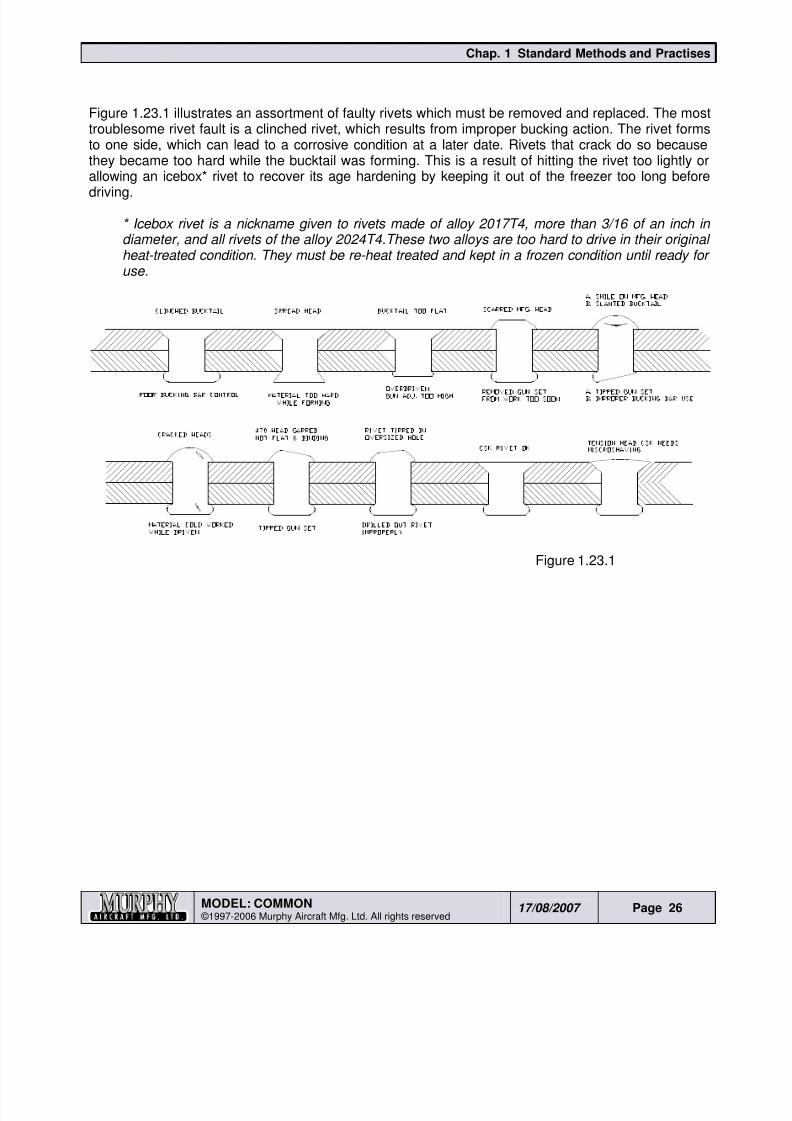
Figure 1.23.1 illustrates an assortment of faulty rivets which must be removed and replaced. The mosttroublesome rivet fault is a clinched rivet, which results from improper bucking action. The rivet formsto one side, which can lead to a corrosive condition at a later date. Rivets that crack do so becausethey became too hard while the bucktail was forming. This is a result of hitting the rivet too lightly orallowing an icebox* rivet to recover its age hardening by keeping it out of the freezer too long before
driving.
* Icebox rivet is a nickname given to rivets made of alloy 2017T4, more than 3/16 of an inch indiameter, and all rivets of the alloy 2024T4.These two alloys are too hard to drive in their originalheat-treated condition. They must be re-heat treated and kept in a frozen condition until ready foruse.
Figure 1.23.1
8/19/2019 Ch01 Standard Methods and Practises
http://slidepdf.com/reader/full/ch01-standard-methods-and-practises 27/44
Chap. 1 Standard Methods and Practises
MODEL: COMMON ©1997-2006 Murphy Aircraft Mfg. Ltd. All rights reserved
17/08/2007 Page 27
1.24 Fiberglass Construction
Fairings, cowlings and wing tips for the aircraft are fiberglass; you will be required to work withfibreglass to fit these parts. You will be required to purchase enough fiberglass cloth, resin and
catalyst to complete and fit these parts.
It is highly recommended that the builder review the construction of the fairing sections at thistime in order to understand the work they need to perform.
The following list has some recommendations about using fiberglass.
As the windshield installation involves the use of fiberglass, it is suggested that the builder installthe windshield before working on the fairings. This will give the builder practice using fiberglass.
If a builder chooses to follow our instructions, a proven fairing will result; the builder may also
employ some of his/her own creativity into the construction.
Keep the weave of the cloth straight and mark your cuts with a black felt pen. Cut the cloth withsharp scissors.
If the fiberglass cloth lies smoothly while dry, it will easily conform to the mold when wetted outwith resin.
Keep the fiberglass cloth clean. If possible, keep it in an area away from where you will be usingthe resin. Oil, dirt or solvents will deteriorate the cloth and prevent the resin from properlybonding to the cloth.
It is much easier to handle fiberglass cloth if you spread it over a smooth slick surface. Keep theloose ends of the fiberglass trimmed if possible.
Keep all necessary tools at hand. Ensure you have good light and work in a well ventilated area.Keep the room temperature between 68 to 80 degrees Fahrenheit.
Always abide by the instructions and warning labels provided on the resin containers.
Allow yourself plenty of time to work with the fiberglass and resin.
If more information is required about the use of fiberglass or lay-up procedures, an excellent referencebook is Sportplane Construction Techniques by Tony Bingelis. This book can be purchased at any EAA
Bookstore or EAA Chapter.
8/19/2019 Ch01 Standard Methods and Practises
http://slidepdf.com/reader/full/ch01-standard-methods-and-practises 28/44
Chap. 1 Standard Methods and Practises
MODEL: COMMON ©1997-2006 Murphy Aircraft Mfg. Ltd. All rights reserved
17/08/2007 Page 28
1.25 Making Gussets
A gusset is a flat, often triangular plate, used to connect and reinforce a joint where severalmembers meet at different angles. In this section we show the method by which gussets can be
made easily and that will fit and function correctly.
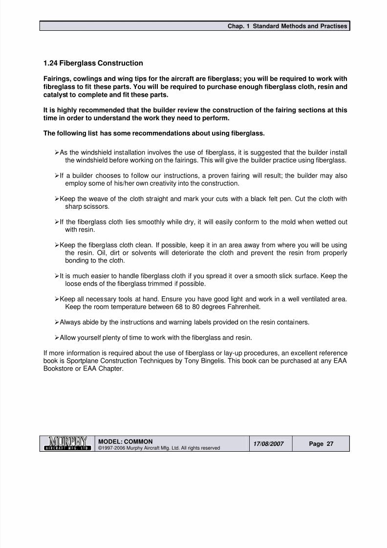
Figure 1.25.11. Where a gusset is required, decide the size and number of rivet holes to be reinforced. Cut a
piece of the appropriate material to a size greater than the holes to be covered. See Figure1.25.1.
2. If possible, backdrill through the rivet holes. Cleco while drilling.
3. If unable to backdrill, another method to transfer the hole pattern needs to be sought.
It may be possible to use a ‘hole finder’ as pictured
4. Remove the gusset.
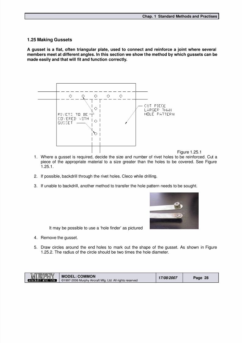
5. Draw circles around the end holes to mark out the shape of the gusset. As shown in Figure1.25.2. The radius of the circle should be two times the hole diameter.
8/19/2019 Ch01 Standard Methods and Practises
http://slidepdf.com/reader/full/ch01-standard-methods-and-practises 29/44
Chap. 1 Standard Methods and Practises
MODEL: COMMON ©1997-2006 Murphy Aircraft Mfg. Ltd. All rights reserved
17/08/2007 Page 29
Figure 1.25.2
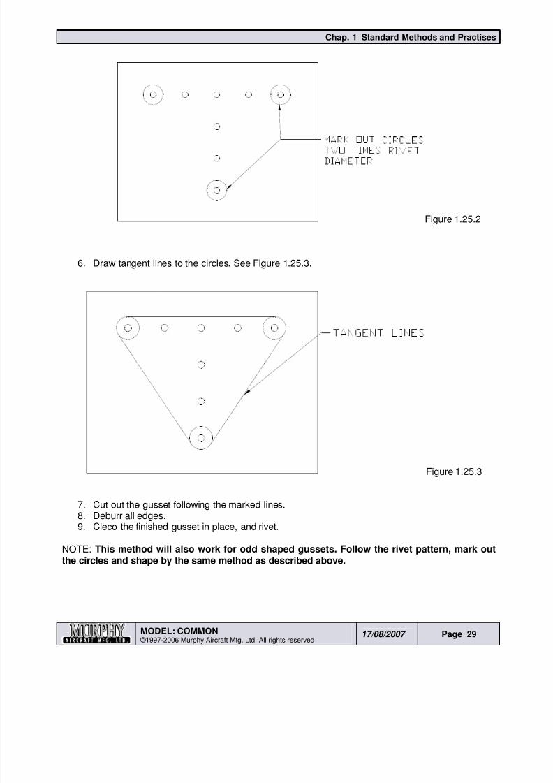
6. Draw tangent lines to the circles. See Figure 1.25.3.
Figure 1.25.3
7. Cut out the gusset following the marked lines.8. Deburr all edges.
9. Cleco the finished gusset in place, and rivet.
NOTE: This method will also work for odd shaped gussets. Follow the rivet pattern, mark outthe circles and shape by the same method as described above.
8/19/2019 Ch01 Standard Methods and Practises
http://slidepdf.com/reader/full/ch01-standard-methods-and-practises 30/44
Chap. 1 Standard Methods and Practises
MODEL: COMMON ©1997-2006 Murphy Aircraft Mfg. Ltd. All rights reserved
17/08/2007 Page 30
1.26 Using Sealant
WARNING –
When using sealants:-• Always wear good quality rubber gloves.
• Avoid getting sealant on your skin. If sealant does get on to your skin, use a brush and soapywater to remove. – do not use solvent, M.E.K. etc. on skin.
• Always work in a well ventilated area.
To prepare surfaces ready for applying sealant, use a Scotchbrite pad and scuff surfaces well.
Immediately before applying sealant, ensure all surfaces are clean and free of dust particles.
DO NOT USE ANY SOLVENT OR M.E.K. AFTER SCOTCHBRITING THE SURFACE
The sealant used is a two part mixture. It is very important that the mix ratio specified by themanufacturer is adhered to exactly and that it is used at room temperature. Improper mix ratio ortoo low a temperature may slow or stop the sealant from curing.
A small inexpensive digital scale is very useful in ensuring the right mixture.
Only mix enough sealant to do the job, it cannot be stored. It is better to under estimate and run outbefore completing an assembly. You can always mix a little more to finish up. Working time isabout 2 hrs.
The best way to mix the sealant is on a flat sheet of material, such as aluminum. Use a putty knifeor a piece of aluminum to mix.
When mixing, scrape sealant upwards from mixing surface to make ensure a complete and smoothand even mix.
How much do I use? - After riveting you should see a small amount of sealer being squeezed outall along the joint.
1.27 Do’s and Don’ts in Handling Aluminum Sheets
Do - use a soft leaded pencil or a fine tip felt pen to mark aluminum sheet.
Do - bend aluminum where possible so the flange bend line runs perpendicular to the metalgrain (direction or rolling).
Do - use the recommended minimum or larger bend radius in bending aluminum sheet.
Do - use a protective layer between adjacent alclad sheets.
Do - store aluminum sheet in a dry area.
Don’t - scratch the surface of aluminum – retain plastic film or protect sheet againstabrasion.

8/19/2019 Ch01 Standard Methods and Practises
http://slidepdf.com/reader/full/ch01-standard-methods-and-practises 31/44
Chap. 1 Standard Methods and Practises
MODEL: COMMON ©1997-2006 Murphy Aircraft Mfg. Ltd. All rights reserved
17/08/2007 Page 31
Don’t -use a brown sulphite sand paper -this paper, when wet, will cause corrosion

8/19/2019 Ch01 Standard Methods and Practises
http://slidepdf.com/reader/full/ch01-standard-methods-and-practises 32/44
Chap. 1 Standard Methods and Practises
MODEL: COMMON ©1997-2006 Murphy Aircraft Mfg. Ltd. All rights reserved
17/08/2007 Page 32
1.28 Cable Rigging
Follow the instructions that come with the nico press tools you use. It is very important that aGO-NO gauge or callipers are used after crimping to ensure the crimping is complete.
.
8/19/2019 Ch01 Standard Methods and Practises
http://slidepdf.com/reader/full/ch01-standard-methods-and-practises 33/44
Chap. 1 Standard Methods and Practises
MODEL: COMMON ©1997-2006 Murphy Aircraft Mfg. Ltd. All rights reserved
17/08/2007 Page 33
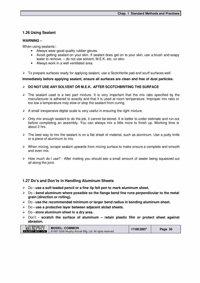
1.29 Push Pull Tube Fabrication
The following is a standard practice for manufacturing the push pull tubes used throughout the aircraft.
The example shown is for the 1/4” (HM-4M) Rod End Bearing in 3/4” x .035 tubing. Other combinations
are:• 1/4” HM-4M Rod End Bearing, AN316-4 Jam Nut and CC-28 End Plug for 1” x .058 tubing
• 5/16” HM-5M Rod End Bearing, AN316-5 Jam Nut and CC-30 End Plug for 1” x .058 tubing.
To determine the length of the tubing between the two Rod End Bearings:-
Figure 1.29.1
Calculate or measure the total length required between centers of the rod end bearings.
Add together: 2 x the head of the end plugs and 2 x [the thickness of the jam nut plus 3 to 5threads plus distance from top thread to center of the rod end].
Deduct the sum from the total length required.
Cut the tube and deburr the ends.
Insert the appropriate CC End Plug.
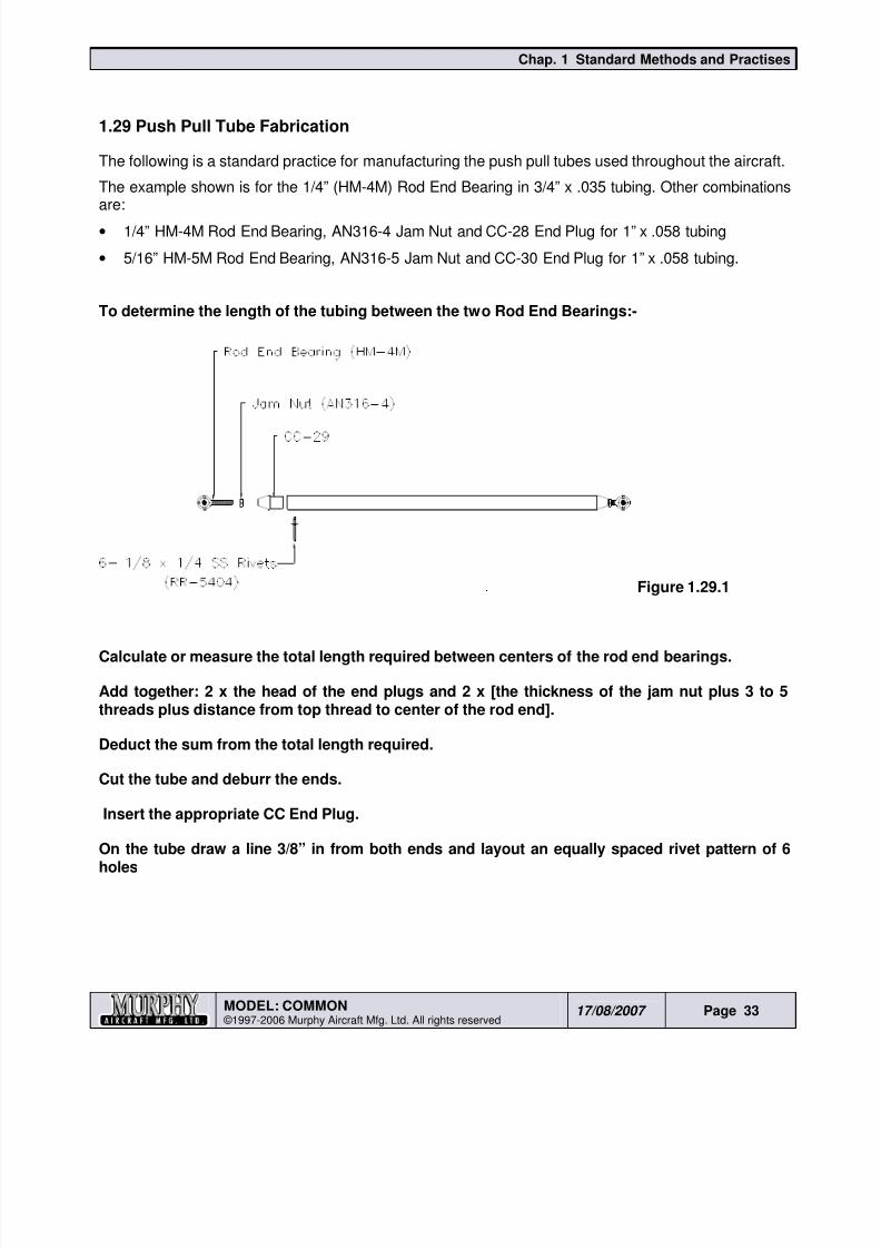
On the tube draw a line 3/8” in from both ends and layout an equally spaced rivet pattern of 6holes
8/19/2019 Ch01 Standard Methods and Practises
http://slidepdf.com/reader/full/ch01-standard-methods-and-practises 34/44
Chap. 1 Standard Methods and Practises
MODEL: COMMON ©1997-2006 Murphy Aircraft Mfg. Ltd. All rights reserved
17/08/2007 Page 34
Drill #30 holes. Remove the End Plugs. Deburr, zinc chromate and re-install the parts
Rivet together using RR-5404 1/8” x 1/4” SS rivet.
1.30 Reamers
The reamer is a tool used to produce holes of very close tolerances. Reamers are available in a rangeof sizes and types to cover the various hole diameters.
In using the reamer there are several pointers that bear mentioning:
Be sure the reamer is lined up perfectly with the hole.
Never remove more than 0.012 of material in one operation.
A reamer should never be turned backward after the reaming operation has been started.
8/19/2019 Ch01 Standard Methods and Practises
http://slidepdf.com/reader/full/ch01-standard-methods-and-practises 35/44
Chap. 1 Standard Methods and Practises
MODEL: COMMON ©1997-2006 Murphy Aircraft Mfg. Ltd. All rights reserved
17/08/2007 Page 35
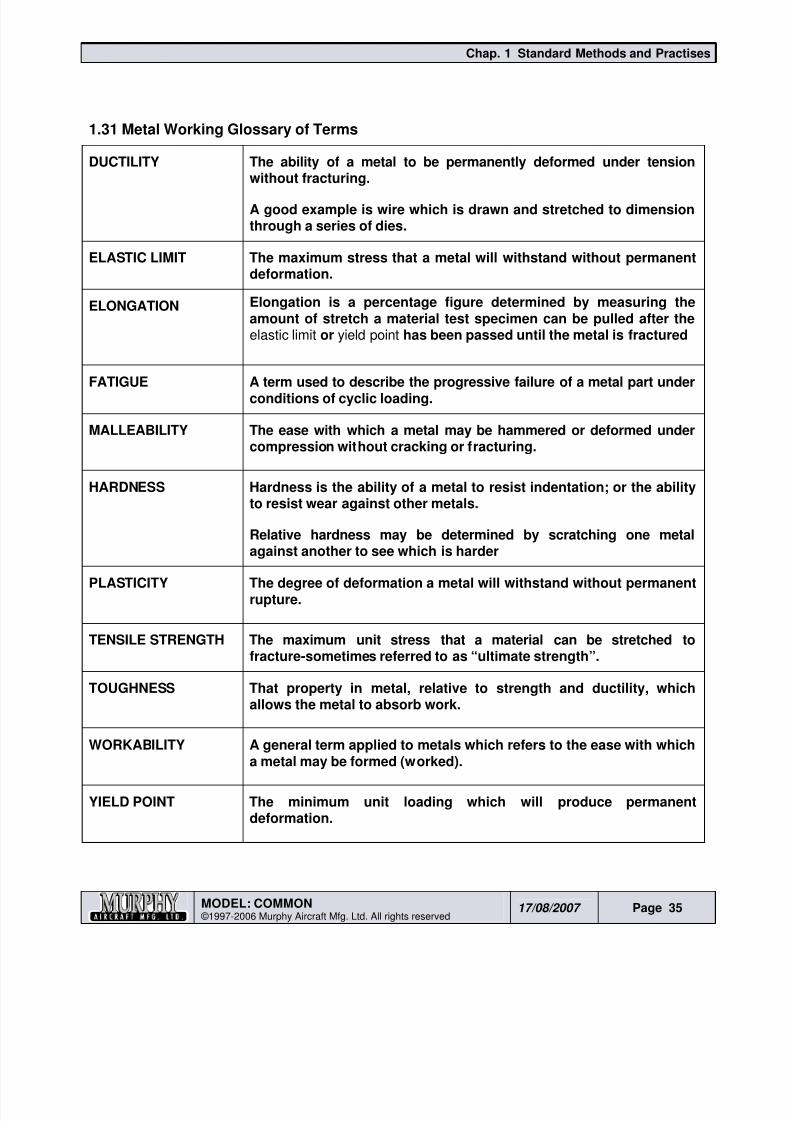
1.31 Metal Working Glossary of Terms
DUCTILITY The ability of a metal to be permanently deformed under tensionwithout fracturing.
A good example is wire which is drawn and stretched to dimensionthrough a series of dies.
ELASTIC LIMIT The maximum stress that a metal will withstand without permanentdeformation.
ELONGATION Elongation is a percentage figure determined by measuring theamount of stretch a material test specimen can be pulled after theelastic limit or yield point has been passed until the metal is fractured
FATIGUE A term used to describe the progressive failure of a metal part underconditions of cyclic loading.
MALLEABILITY The ease with which a metal may be hammered or deformed undercompression without cracking or fracturing.
HARDNESS Hardness is the ability of a metal to resist indentation; or the abilityto resist wear against other metals.
Relative hardness may be determined by scratching one metalagainst another to see which is harder
PLASTICITY The degree of deformation a metal will withstand without permanentrupture.
TENSILE STRENGTH The maximum unit stress that a material can be stretched tofracture-sometimes referred to as “ultimate strength”.
TOUGHNESS That property in metal, relative to strength and ductility, whichallows the metal to absorb work.
WORKABILITY A general term applied to metals which refers to the ease with which
a metal may be formed (worked).
YIELD POINT The minimum unit loading which will produce permanentdeformation.
8/19/2019 Ch01 Standard Methods and Practises
http://slidepdf.com/reader/full/ch01-standard-methods-and-practises 36/44
Chap. 1 Standard Methods and Practises
MODEL: COMMON ©1997-2006 Murphy Aircraft Mfg. Ltd. All rights reserved
17/08/2007 Page 36
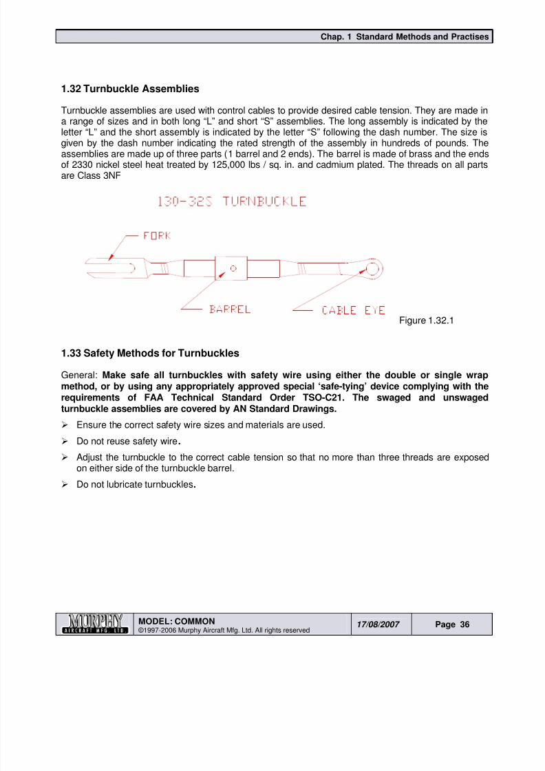
1.32 Turnbuckle Assemblies
Turnbuckle assemblies are used with control cables to provide desired cable tension. They are made ina range of sizes and in both long “L” and short “S” assemblies. The long assembly is indicated by the
letter “L” and the short assembly is indicated by the letter “S” following the dash number. The size isgiven by the dash number indicating the rated strength of the assembly in hundreds of pounds. Theassemblies are made up of three parts (1 barrel and 2 ends). The barrel is made of brass and the endsof 2330 nickel steel heat treated by 125,000 lbs / sq. in. and cadmium plated. The threads on all partsare Class 3NF
Figure 1.32.1
1.33 Safety Methods for Turnbuckles
General: Make safe all turnbuckles with safety wire using either the double or single wrap
method, or by using any appropriately approved special ‘safe-tying’ device complying with therequirements of FAA Technical Standard Order TSO-C21. The swaged and unswagedturnbuckle assemblies are covered by AN Standard Drawings.
Ensure the correct safety wire sizes and materials are used.
Do not reuse safety wire.
Adjust the turnbuckle to the correct cable tension so that no more than three threads are exposedon either side of the turnbuckle barrel.
Do not lubricate turnbuckles.
8/19/2019 Ch01 Standard Methods and Practises
http://slidepdf.com/reader/full/ch01-standard-methods-and-practises 37/44
Chap. 1 Standard Methods and Practises
MODEL: COMMON ©1997-2006 Murphy Aircraft Mfg. Ltd. All rights reserved
17/08/2007 Page 37
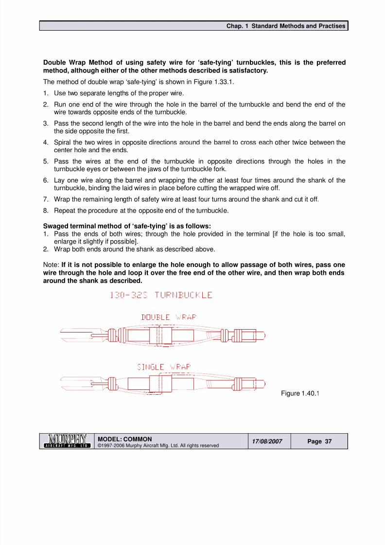
Double Wrap Method of using safety wire for ‘safe-tying’ turnbuckles, this is the preferredmethod, although either of the other methods described is satisfactory.
The method of double wrap ‘safe-tying’ is shown in Figure 1.33.1.
1. Use two separate lengths of the proper wire.
2. Run one end of the wire through the hole in the barrel of the turnbuckle and bend the end of thewire towards opposite ends of the turnbuckle.
3. Pass the second length of the wire into the hole in the barrel and bend the ends along the barrel onthe side opposite the first.
4. Spiral the two wires in opposite directions around the barrel to cross each other twice between thecenter hole and the ends.
5. Pass the wires at the end of the turnbuckle in opposite directions through the holes in theturnbuckle eyes or between the jaws of the turnbuckle fork.
6. Lay one wire along the barrel and wrapping the other at least four times around the shank of theturnbuckle, binding the laid wires in place before cutting the wrapped wire off.
7. Wrap the remaining length of safety wire at least four turns around the shank and cut it off.
8. Repeat the procedure at the opposite end of the turnbuckle.
Swaged terminal method of ‘safe-tying’ is as follows: 1. Pass the ends of both wires; through the hole provided in the terminal [if the hole is too small,
enlarge it slightly if possible].2. Wrap both ends around the shank as described above.
Note: If it is not possible to enlarge the hole enough to allow passage of both wires, pass onewire through the hole and loop it over the free end of the other wire, and then wrap both endsaround the shank as described.
Figure 1.40.1
8/19/2019 Ch01 Standard Methods and Practises
http://slidepdf.com/reader/full/ch01-standard-methods-and-practises 38/44
Chap. 1 Standard Methods and Practises
MODEL: COMMON ©1997-2006 Murphy Aircraft Mfg. Ltd. All rights reserved
17/08/2007 Page 38
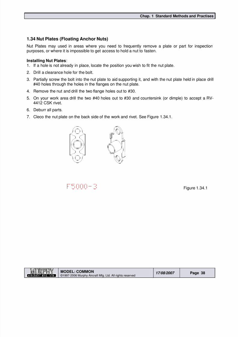
1.34 Nut Plates (Floating Anchor Nuts)
Nut Plates may used in areas where you need to frequently remove a plate or part for inspectionpurposes, or where it is impossible to get access to hold a nut to fasten.
Installing Nut Plates:1. If a hole is not already in place, locate the position you wish to fit the nut plate.
2. Drill a clearance hole for the bolt.
3. Partially screw the bolt into the nut plate to aid supporting it, and with the nut plate held in place drill#40 holes through the holes in the flanges on the nut plate.
4. Remove the nut and drill the two flange holes out to #30.
5. On your work area drill the two #40 holes out to #30 and countersink (or dimple) to accept a RV-4412 CSK rivet.
6. Deburr all parts.
7. Cleco the nut plate on the back side of the work and rivet. See Figure 1.34.1.
Figure 1.34.1
8/19/2019 Ch01 Standard Methods and Practises
http://slidepdf.com/reader/full/ch01-standard-methods-and-practises 39/44
Chap. 1 Standard Methods and Practises
MODEL: COMMON ©1997-2006 Murphy Aircraft Mfg. Ltd. All rights reserved
17/08/2007 Page 39
1.35 Some Final Thoughts...
The last page of this section contains instructions for building a work table, if you do not have one. Anytable will do as long as it is sufficient in size and robust enough to build all the components on. Themost important and critical thing is to ensure that the table is absolutely flat, containing no twists. Any
twist in the table will translate into twisted aircraft sections, which usually results in an aircraft thatdoesn’t fly straight hands off.
When you are reading the drawings, you will see both solid and dashed lines. This is standard drawingpractice and the solid lines denote the top most [visible] layer of material while dashed lines denote apart or material layer hidden [non visible] beneath another.
A common request throughout the manual is for you to draw a center line down the flange of parts.This center line is used for lining up the part with a pre-punched hole in another part. This line, drawnwith a felt pen, is for reference only and does not to be 100% accurate.
We have heard many stories of builders spending numerous hours measuring and drawing linesor creating apparatus to do the same. Such extremes are not necessary. At Murphy Aircraft, we
simply hold the felt pen between the thumb and forefinger and use the middle finger as a gauge.By eyeball estimating only, put the tip of the pen in the center of the flange and using the middlefinger as a slider, run the pen along the part, drawing your middle line.
Cleco, Cleco pliers, #40 holes, #30 holes. If these are strange sounding words, about a thousandhours from now they will be second nature to you.
A Cleco is a temporary “clamp” that utilizes existing pre-punched holes to secure parts to eachother.
Cleco pliers are used to install/remove Clecos. Clecos come in four colors to help differentiate between sizes.
• Silver Clecos are 3/32” and are used in #40 holes.
• Brass Clecos are 1/8” and are used in #30 holes.
•
Gold Clecos are 3/16” and are used in #11 holes.• Black Clecos are 5/32” and are used in #21 holes.
The majority of holes in the pre-punched panels are #40. These are pilot holes, and using 3/32” Clecos(silver) allow for aligning of parts for final drilling. As you drill out the holes to the required size, try toplace Cleco every forth or fifth hole to ensure proper part alignment. When the #40 holes are drilled outto #30, to maintain correct location, drill the first hole then fit a 1/8” Cleco (brass) into it beforeremoving the next 3/32” Cleco ready to drill, repeat hole by hole, replacing the small for the largeClecos as you go.
Before beginning construction of each component, read the relevant manual section to gain a fullunderstanding of what is required before starting, it may mean reading more than once and be referredto again during building.
Whenever possible, lay the all the parts out in order on the table as per the exploded drawings at thebeginning of the section. This will help to gain a better understanding of what you are building and theroute you have to take to do so. Also errors are less likely to occur.
8/19/2019 Ch01 Standard Methods and Practises
http://slidepdf.com/reader/full/ch01-standard-methods-and-practises 40/44
Chap. 1 Standard Methods and Practises
MODEL: COMMON ©1997-2006 Murphy Aircraft Mfg. Ltd. All rights reserved
17/08/2007 Page 40
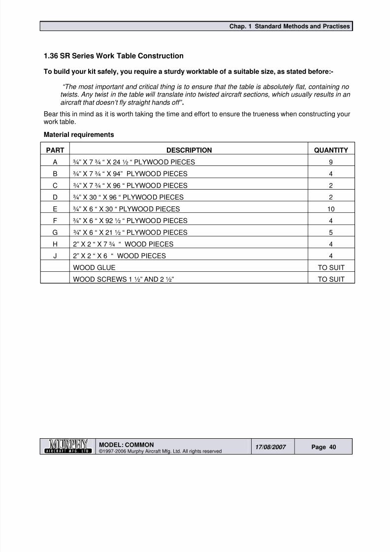
1.36 SR Series Work Table Construction
To build your kit safely, you require a sturdy worktable of a suitable size, as stated before:-
“The most important and critical thing is to ensure that the table is absolutely flat, containing no
twists. Any twist in the table will translate into twisted aircraft sections, which usually results in anaircraft that doesn’t fly straight hands off” .
Bear this in mind as it is worth taking the time and effort to ensure the trueness when constructing yourwork table.
Material requirements
PART DESCRIPTION QUANTITY
A ¾” X 7 ¾ “ X 24 ½ “ PLYWOOD PIECES 9
B ¾” X 7 ¾ “ X 94” PLYWOOD PIECES 4
C ¾” X 7 ¾ “ X 96 “ PLYWOOD PIECES 2D ¾” X 30 “ X 96 “ PLYWOOD PIECES 2
E ¾” X 6 “ X 30 “ PLYWOOD PIECES 10
F ¾” X 6 “ X 92 ½ “ PLYWOOD PIECES 4
G ¾” X 6 “ X 21 ½ “ PLYWOOD PIECES 5
H 2” X 2 “ X 7 ¾ “ WOOD PIECES 4
J 2” X 2 “ X 6 “ WOOD PIECES 4
WOOD GLUE TO SUIT
WOOD SCREWS 1 ½” AND 2 ½” TO SUIT
8/19/2019 Ch01 Standard Methods and Practises
http://slidepdf.com/reader/full/ch01-standard-methods-and-practises 41/44
Chap. 1 Standard Methods and Practises
MODEL: COMMON ©1997-2006 Murphy Aircraft Mfg. Ltd. All rights reserved
17/08/2007 Page 41
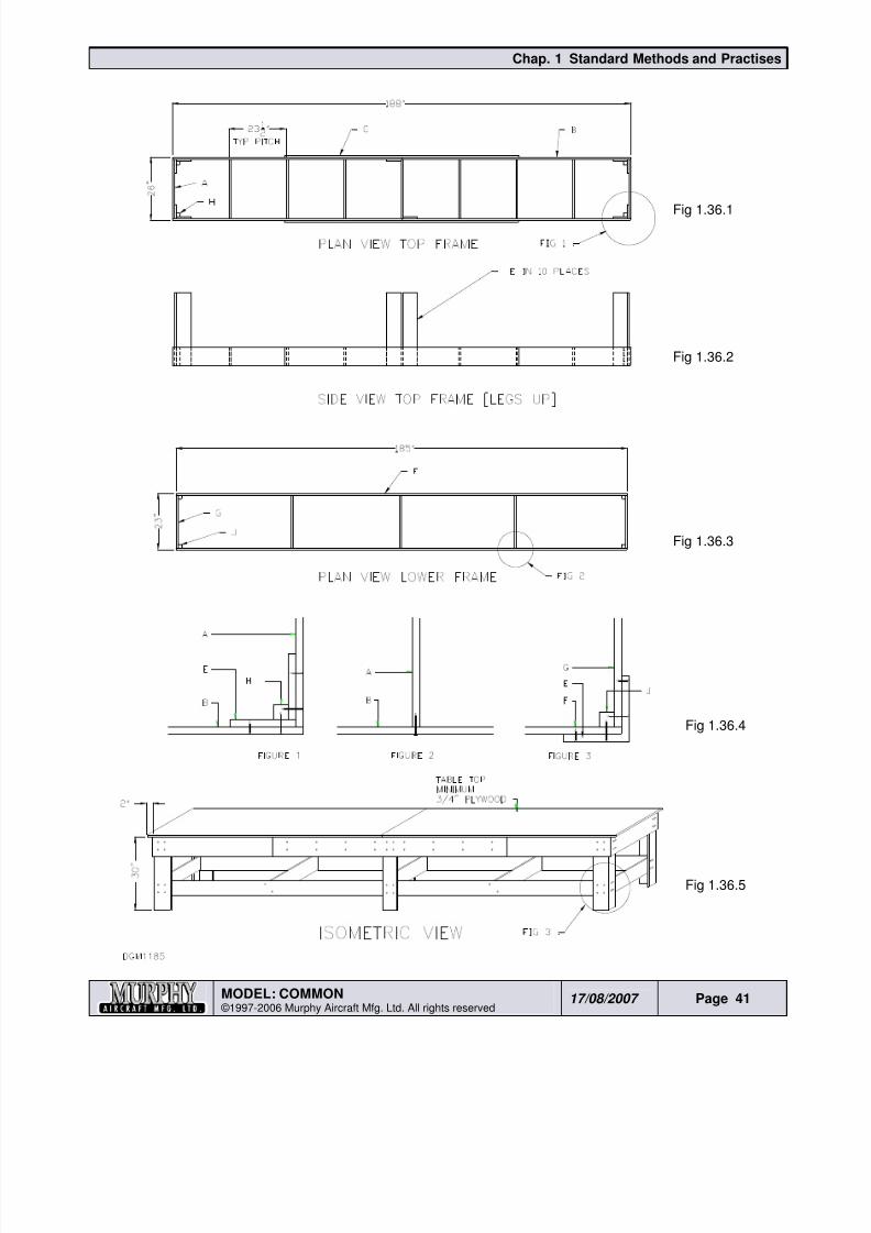
Fig 1.36.1
Fig 1.36.2
Fig 1.36.3
Fig 1.36.4
Fig 1.36.5
8/19/2019 Ch01 Standard Methods and Practises
http://slidepdf.com/reader/full/ch01-standard-methods-and-practises 42/44
Chap. 1 Standard Methods and Practises
MODEL: COMMON ©1997-2006 Murphy Aircraft Mfg. Ltd. All rights reserved
17/08/2007 Page 42
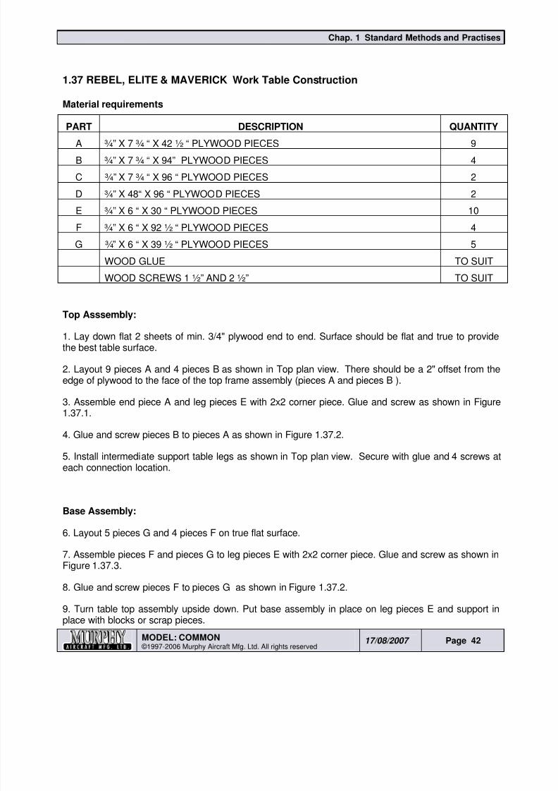
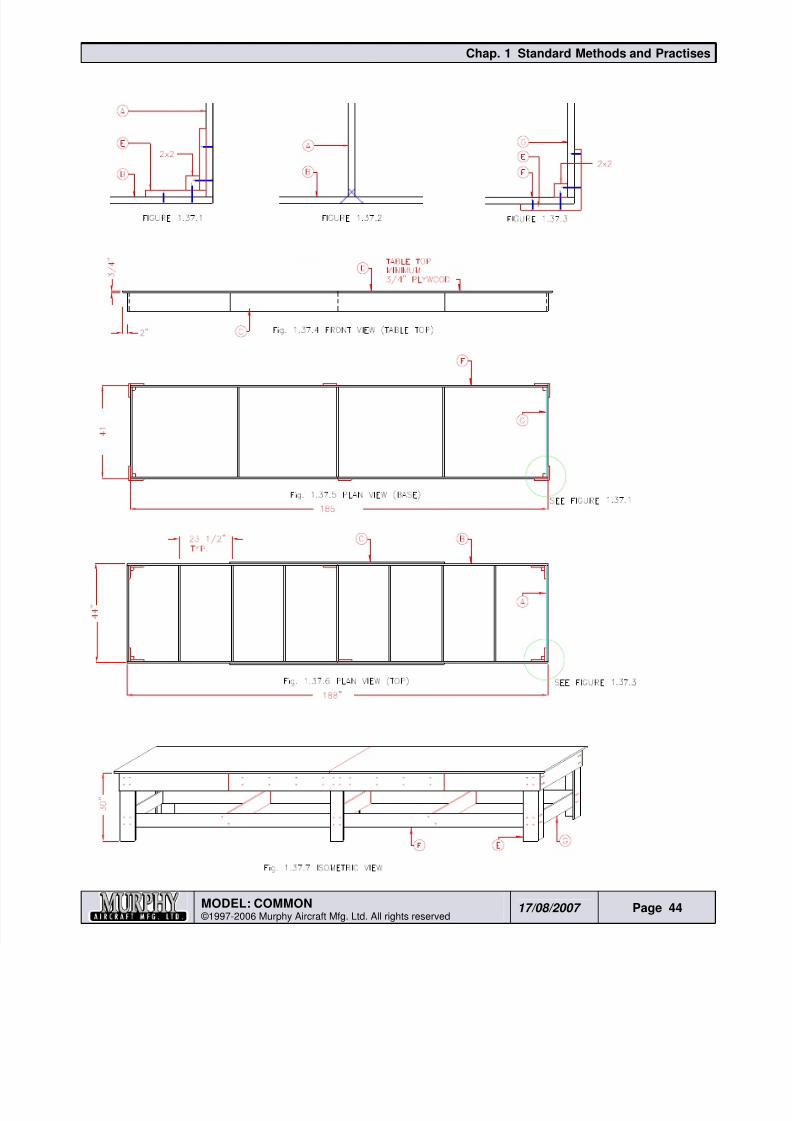
1.37 REBEL, ELITE & MAVERICK Work Table Construction
Material requirements
PART DESCRIPTION QUANTITY
A ¾” X 7 ¾ “ X 42 ½ “ PLYWOOD PIECES 9
B ¾” X 7 ¾ “ X 94” PLYWOOD PIECES 4
C ¾” X 7 ¾ “ X 96 “ PLYWOOD PIECES 2
D ¾” X 48“ X 96 “ PLYWOOD PIECES 2
E ¾” X 6 “ X 30 “ PLYWOOD PIECES 10
F ¾” X 6 “ X 92 ½ “ PLYWOOD PIECES 4
G ¾” X 6 “ X 39 ½ “ PLYWOOD PIECES 5
WOOD GLUE TO SUIT
WOOD SCREWS 1 ½” AND 2 ½” TO SUIT
Top Asssembly:
1. Lay down flat 2 sheets of min. 3/4" plywood end to end. Surface should be flat and true to providethe best table surface.
2. Layout 9 pieces A and 4 pieces B as shown in Top plan view. There should be a 2" offset from theedge of plywood to the face of the top frame assembly (pieces A and pieces B ).
3. Assemble end piece A and leg pieces E with 2x2 corner piece. Glue and screw as shown in Figure1.37.1.
4. Glue and screw pieces B to pieces A as shown in Figure 1.37.2.
5. Install intermediate support table legs as shown in Top plan view. Secure with glue and 4 screws ateach connection location.
Base Assembly:
6. Layout 5 pieces G and 4 pieces F on true flat surface.
7. Assemble pieces F and pieces G to leg pieces E with 2x2 corner piece. Glue and screw as shown inFigure 1.37.3.
8. Glue and screw pieces F to pieces G as shown in Figure 1.37.2.
9. Turn table top assembly upside down. Put base assembly in place on leg pieces E and support inplace with blocks or scrap pieces.
8/19/2019 Ch01 Standard Methods and Practises
http://slidepdf.com/reader/full/ch01-standard-methods-and-practises 43/44
Chap. 1 Standard Methods and Practises
MODEL: COMMON ©1997-2006 Murphy Aircraft Mfg. Ltd. All rights reserved
17/08/2007 Page 43
Glue and install 4 screws at all connecting locations. See isometric view.
Table Surface:
10. With assembled top frame sitting on plywood sheets mark a pencil line along edges of all framepieces. Lift frame about 2" off plywood and hold up with temporary blocks. Lay down a bead of gluebetween all pencil lines, and let frame down onto plywood sheets. Clamp plywood sheets to top frameassembly.
11. Flip entire top assembly and plywood over to right side up with clamps secured in place. Snap achalk line along centerlines of pieces A and pieces B on top side of plywood.
12. Drill, countersink and install screws at 12" o/c through plywood to all pieces A and pieces B .
13. Attach stiffener pieces C to o/s face of pieces B and install a double row of screws at 12" o/c.
8/19/2019 Ch01 Standard Methods and Practises
http://slidepdf.com/reader/full/ch01-standard-methods-and-practises 44/44
Chap. 1 Standard Methods and Practises


![Xcelsius Best Practises[1]](https://img.pdfslide.us/doc/110x75/547af7fdb4af9fce158b4d11/xcelsius-best-practises1.jpg)