Embed Size (px)
Citation preview


Labour-intensive
Public Works
Small earth dams and dugouts
Training guide and technical reference for LIPW personnel
Ghana Irrigation Development Agency International Labour Office, Geneva

Copyright © International Labour Organization 1988 First published 1988, Second edition 2012
Publications of the International Labour Office enjoy copyright under Protocol 2 of the Universal Copyright Convention. Nevertheless, short excerpts from them may be reproduced without authorization, on condition that the source is indicated. For rights of reproduction or translation, application should be made to ILO Publications (Rights and Permissions), International Labour Office, CH-1211 Geneva 22, Switzerland, or by email: [email protected]. The International Labour Office welcomes such applications.
Libraries, institutions and other users registered with reproduction rights organizations may make copies in accordance with the licences issued to them for this purpose. Visit www.ifrro.org to find the reproduction rights organization in your country. ISBN 92-2-105944-8 (print); xxxxxxxx (web pdf)
International Labour Organization; small earth dam construction and maintenance / rural public works / labour-intensive employment / rural employment / poverty alleviation
ILO Cataloguing in Publication Data The designations employed in ILO publications, which are in conformity with United Nations practice, and the presentation of material therein do not imply the expression of any opinion whatsoever on the part of the International Labour Office concerning the legal status of any country, area or territory or of its authorities, or concerning the delimitation of its frontiers.
The responsibility for opinions expressed in signed articles, studies and other contributions rests solely with their authors, and publication does not constitute an endorsement by the International Labour Office of the opinions expressed in them. Reference to names of firms and commercial products and processes does not imply their endorsement by the International Labour Office, and any failure to mention a particular firm, commercial product or process is not a sign of disapproval.
ILO publications can be obtained through major booksellers or ILO local offices in many countries, or direct from ILO Publications, International Labour Office, CH-1211 Geneva 22, Switzerland. Catalogues or lists of new publications are available free of charge from the above address, or by email: [email protected]
Visit our website: www.ilo.org/publns and www.ilo.org/eiip
This revision has been prepared in support of the Ghana Social Opportunities Project, the first version being produced with support from the UNDP and the German government.

Small earth dams and dugouts page
Table of contents iii
Contents page
Preliminary considerations v Notes on organising and conducting the training vi I Introduction vi
1 Purpose of training vi 2 Who needs training? vii 3 What do they need to be trained to do? viii
II Organising the training ix 1 Suggested training programme x 2 Training material xv 3 General advice to trainers xvi 4 Course evaluation xviii
1 General description 1 1.1 Function 1 1.2 Different types of earth dams 3 1.3 Main components of an earth dam 6
2 Location of the dam 17 2.1 Selection of dam site 17 2.2 Water requirements 19 2.3 Run-off estimate 21 2.4 Reservoir capacity 21
3 Embankment design 26 3.1 Locating and identifying construction material 26 3.2 Selecting appropriate soil material 27 3.3 Dam foundation 36 3.4 Embankment cross-section 39
4 The spillway 52 4.1 General considerations 52 4.2 Central spillway 55 4.3 Side spillway 55

Small earth dams and dugouts page
Table of contents iv
5 Constructing the dam 59 5.1 Setting out the dam 59 5.2 Clearing the dam site 65 5.3 Constructing a temporary cofferdam 66 5.4 Preparing the foundation 67 5.5 Timing of ancillary works 69 5.6 Excavating the cut-off trench 69 5.7 Excavating fill material from borrow pits 71 5.8 Transporting the fill material 76 5.9 Compaction 85 5.10 Other construction activities 98 5.11 Work organisation 100
6 Dam repair and maintenance 107 6.1 Settlement control 108 6.2 Seepage control 113 6.3 Sliding 116 6.4 Repairing a dam break 119 6.5 Maintenance of slopes 126 6.6 Burrowing animals 128 6.7 Maintaining the crest 129 6.8 Maintenance of ancillary structures 130 6.9 Silting of reservoir 132 6.10 Catchment protection 134 6.11 Monitoring and inspection 140 6.12 Community involvement 144
7 Dugouts and hillside dams 148 7.1 General 148 7.2 Design of hillside dams and dugouts 149 7.3 Location 151 7.4 Silt traps 151 7.5 Spillways 152 7.6 Construction 152 7.7 Soil bunds 154

Small earth dams and dugouts page
Organising the training v
Preliminary considerations The aim of the technical guide is to assist in the training of technical personnel in charge of the design, construction and maintenance of small earth dams undertaken in the context of Labour-intensive Public Works (LIPW). The presented methods and design principles are simple, easily implemented and can be applied to small structures of limited height and storage capacity where labour-intensive techniques are appropriate. On the other hand, this guide does not presume to set forward all design methods and construction techniques. For more comprehensive works, it may be necessary to call in specialists in this type of civil engineering. This document can be used as a technical reference guide for site personnel, as a reminder of basic principles involved in dam design and construction. It can also be used as a training guide. In this case, the trainer should refer to the trainer’s notes at the start and in the footnotes provided.

Small earth dams and dugouts page
Organising the training vi
Notes on organising and conducting the training I Introduction This document is concerned with the design, construction and maintenance of small earth dams.1 It can be used in many ways: as a simple reference manual, or field guide for technical personnel - or as a training guide to be used in the context of a training course. This section is intended to advise trainers on how to use this document during a training course. The tasks involved in design, construction and maintenance are, of course, quite different and are usually carried out by different categories of staff. Chapters 2, 3 and 4 fall under the broad heading of dam design while Chapters 5 and 6 treat the more operational aspects of dam construction and maintenance. The Guide needs not and indeed usually should not be taught cover to cover. Rather, training sessions should be tailor-made for the particular training needs in the programme. Therefore, before beginning any training programme it is important to ask three simple questions:
(i) What is the purpose of the training? (ii) Who in the project needs training? (iii) What jobs do they need to be trained to do?
1 Purpose of training Carrying out training takes up valuable time and costs money. Before commencing any training programme it is essential to first make sure that it is necessary. Training should be carried out in response to particular problems facing a project. The "problem" faced by many 1 The height of small earth dams built using labour-intensive methods seldom
exceeds 10 metres and in most cases considerably less.

Small earth dams and dugouts page
Organising the training vii
public works programmes may simply be the fact that project personnel has never been involved before in small dam construction - and that training is required to acquaint them with this new and unfamiliar subject. Other problems may be encountered once a project is already underway. These problems can take many forms. Perhaps a dam is seeping and requires corrective action. Perhaps workers are not able to compact earthwork on the embankment satisfactorily. Whatever the problem, always keep in mind that addressing these issues is the goal of the training. Providing training can be an effective measure to solve a problem. Do not waste time and resources in carrying out training for training's sake. This guide therefore needs to be adapted to fit the training needs found in a particular programme. Feel free to leave out sections which do not apply to a particular situation and also feel free to include new material which is not contained in this Guide which may be required for the particular training needs identified. 2 Who needs training? The contents of this Guide can be adapted to fit different categories of trainees, each concerned with particular aspects of small dam construction. Before embarking on the training, establish a clear view of who will be trained. This means knowing not only what particular job tasks the personnel are required to carry out, but also discovering what the personnel already know and their current level of knowledge, skills and work experience. Generally speaking, the Guide can be adapted for use by site engineers and site foremen, as well as by various categories of intermediate technical personnel.

Small earth dams and dugouts page
Organising the training viii
For project engineers, emphasis is usually given to location and design of dam sites.2 However, engineers also need to have a thorough understanding of the various tasks of dam construction since they will be required to train and instruct their site personnel accordingly. Worksite foremen are mainly concerned with Chapter 5 on dam construction. While foremen do not design dams and ancillary structures, Chapter 3 on Embankment design deals with location of construction materials and investigating the dam foundation, activities with which they are directly concerned. Although it may be helpful for site foremen to understand on what basis a dam site was chosen and how a dam was designed, clearly these tasks should be left to personnel with appropriate qualifications. The training of site foremen should therefore either adapt or omit altogether those sections of the Guide not appropriate for this category of personnel. Finally, training carried out with the aid of this Guide hopefully also benefits skilled and unskilled workers and members of water user organisations who are often key target groups in LIPWs. While the Guide is not designed for direct training of such an audience, site foremen are encouraged to pass on acquired skills, thereby creating greater awareness in the local community in particular in relation to the maintenance and utilisation of the dam. 3 What do they need to be trained to do? Once the programme's training needs have been clearly established and the category and level of personnel to be trained have been
2 The location and design of even small earth dams is not a matter for
amateurs and in many cases, specialised advice and inputs are required. While this Guide covers key elements, which are apt to crop up in the context of labour-intensive public works programmes, the information provided is by no means sufficient to make site engineers fully competent and operational in this regard.

Small earth dams and dugouts page
Organising the training ix
determined, it is useful to identify the specific job tasks which have to be carried out by the trainees. Certain sections of this Guide may not be directly concerned with planned activities but may nevertheless be included in the training in order to create greater awareness and job satisfaction. However, training should be planned around the required jobs - both in the interest of saving time and resources and in order to ensure that new skills learnt as a result of training are put to immediate use. II Organising the training Once it has been decided who to train, and what they will be trained to do, it is possible to start planning the course programme in detail. The training sessions can be carried out anywhere, in a classroom or a nearby community centre or even in a calm, shaded spot outdoors close to a worksite. A plan for a five-day training course is proposed below, covering all topics presented. This schedule can be modified to fit specific training needs and the identified category of personnel. In all likelihood, the training needs will demand that more time is given to each training subject and that the contents of this Guide is divided into several training sessions interspersed with periods of on-the-job training on dam sites. Training sessions should include field visits and numerous practical exercises. The exercises provide the bridge between classroom training sessions and the job the personnel is being trained to do. The trainees should visit at least two dam sites, one new site and one dam under construction. If time permits, several sites presenting different characteristics should be included in the training programme.

Small earth dams and dugouts page
Organising the training x
1 Suggested training programme
1st day Subject: Description of small earth dams (Chapter 1)
Objective: At the end of this session, the trainees should be able to:
• explain the purpose of dams proposed under the programme,
• identify and describe the three different types of earth dams,
• identify and explain the purpose served by the principal components of a dam.
Schedule: morning: training session, presentation and discussion
afternoon: visit to existing dam sites

Small earth dams and dugouts page
Organising the training xi
2nd day Subject: Selection of dam site, calculation of water requirements and dam storage capacity, site investigation (Chapter 2, Chapter 3: 3.1 and 3.2)
Objectives: At the end of this session, the trainees should be able to:
• carry out, in the field, a preliminary reconnaissance of appropriate dam sites, including siting of spillway,
• carry out a site investigation including inspection of the foundation and identify suitable construction materials,
• estimate water requirements of the rural community benefitting from the dam,
• calculate the estimated storage capacity of a proposed dam project.
Schedule: morning: training session, presentation and discussion or lesson in the field
afternoon: visit to a dam site with practical exercises in site reconnaissance, spillway siting, investigating the foundation and identification of construction materials.

Small earth dams and dugouts page
Organising the training xii
3rd day Subject: Embankment and spillway design (Chapter 3: 3.3 and Chapter 4)
Objectives: At the end of this session, the trainees should be able to:
• define the basic design criteria for dam embankments and spillways,
• select the slope gradients appropriate for the embankment materials to be used,
• define appropriate embankment design specifications as related to seepage protection, drains and protection of slopes,
• make a rough estimate of maximum expected flow over a spillway making use of a simple formula,
• define essential design specifications and criteria for central and lateral spillways,
• estimate flow velocity in side spillway channel.
Schedule: morning and afternoon: indoor lessons with practical exercises to be prepared in advance by the trainer.

Small earth dams and dugouts page
Organising the training xiii
4th day Subject: Dam construction (Chapter 5)
Objectives: At the end of this session, the trainees should be able to:
• describe the major work activities involved and precautions to be taken for each of the operations entailed by small earth dam construction.
• These operations include: ü setting out the dam ü clearing the dam site ü construction of a temporary cofferdam
(optional, depending on whether or not a cofferdam is required in the projects)
ü preparing the foundation ü excavating fill materials ü spreading and compaction ü construction of ancillary works.
Schedule: morning: lesson in the field afternoon: practical exercises at on-going dam
construction sites (to be extended based on training needs)3
3 For trainees to demonstrate their ability to carry out any or all of these
operations satisfactorily requires considerably more time than that available in a single day session. The training programme should be modified for this purpose, if necessary to include sessions where the trainees actually carry out these operations. When training worksite supervisors, the course should concentrate almost exclusively on these operations.

Small earth dams and dugouts page
Organising the training xiv
5th day Subject: Dam maintenance (Chapter 6)
Objectives: At the end of this session, the trainees should be able to:
• identify the basic routine maintenance activities required for small earth dams (embankment, spillway and ancillary structures),
• describe how to recognise settlement damage to a dam embankment and describe steps that can be taken to control the situation,
• describe corrective action to be taken in the event of seepage and of sliding of the embankment,
• describe how to correct for siltation of the reservoir.
Schedule: morning: visit to dam requiring maintenance afternoon: training session: presentation and
discussion, Final evaluation of training programme.

Small earth dams and dugouts page
Organising the training xv
2 Training material Before starting the course, the trainer needs to assemble the following material:
ü presentation tools, i.e. a blackboard, white board, flip charts and/or projector
ü board dusters, chalk, marker pens ü survey equipment for the setting out exercises, including:
o levelling instrument o ranging rods o gradient board o transparent water hose o measuring tape o decametre o sledge hammer o pegs
ü equipment for the supervision of the construction4 o templates (gradient triangles) o spirit level
ü tools o pickaxes, shovels, hand rammers, water can, axe, rake
ü other material o survey maps (scale 1:50,000) o planimeter (or transparent millimetre paper) o note pads and pencils
4 The trainer should mention the existence of laboratory equipment to analyse
soils and to check compaction: sieves, proctor equipment, drying oven, etc. A visit to an existing soil laboratory should be organized, if possible.

Small earth dams and dugouts page
Organising the training xvi
3 General advice to trainers (a) Encourage active participation: minimise lecturing There is sometimes a tendency in training courses for the trainer to act like a teacher in school and to read or lecture directly from the training material. This tendency should be avoided. Trainees remember information better if they participate actively in discussions and if there is a free exchange of views and of questions between everyone participating in the course. (b) Guiding the discussion There are times during a discussion when everyone wants to speak at the same time. When such situations arise, the trainer should insist that the group listen to one person at the time. If one speaker holds the floor too long, the trainer needs to interrupt, pointing out that other participants may also want to speak. (c) Listen attentively Equal attention should be paid to each speaker. Listen attentively and let the speaker understand that ideas and opinions expressed are both interesting and relevant. It is sometimes useful to take a brief note of participants’ suggestions while they are speaking, noting them down on a flipchart or blackboard. A summary of these notes may prove useful for later discussions. (d) Emphasise important points Each time the participants makes an important point or expresses an interesting opinion, the trainer should draw the group’s attention to it by repeating the idea in simple terms which are understood by the majority of the trainees.

Small earth dams and dugouts page
Organising the training xvii
(e) Preparing the sessions When trainees only listen to a description of how a particular job should be done, they are apt to forget what they heard. If however, they actually carry out the task concerned, they will remember how to do it. For this reason, every effort should be made to include as many practical exercises and demonstrations as possible, be they carried out on the worksite or in the training room. Practical sessions should always be carefully planned in advance. (f) Recapping A discussion is more than just a conversation. A subject is discussed with an aim in mind. It may occasionally be worthwhile recapping the topic considered and recalling the aim of the discussion by intervening from time to time to give a brief summary of the main points dealt with so far. (g) Questioning An important role of the trainer is to ensure that the atmosphere during training is sufficiently relaxed to allow participants to feel at ease to speak freely. Questions set by the trainer should not be regarded by the trainees as tests. Often there is no strict “right or wrong” answer to a question. Questions should simply give your trainees the opportunity to put forward their individual points of view.

Small earth dams and dugouts page
Organising the training xviii
4 Course Evaluation Make sure that trainees have really learnt how to carry out the jobs they are being trained for. For this reason, it is important to frequently evaluate how effective the training course has been. This evaluation can be done in different ways.
• At times it may be useful to ask questions in order to be sure a presentation has been understood. The questions at the end of this booklet can be used, and the trainer should prepare additional questions drawn from the trainees’ own experience and the project situation;
• The best way to evaluate training is by asking trainees to carry out a particular task required. Such a “task” may be anything from calculating the storage capacity of a dam which is being planned to demonstrating (rather than simply describing) how to protect the embankment of a dam;
• The real test whether a training course has been worthwhile is the trainees’ ability to do their job at the end of the course – and not their ability to recite an answer to any particular question;
• Evaluation should be carried out frequently, in the middle as well as at the end of each training session. This way, it is possible to avoid beginning a new subject before trainees have understood the material already presented;
• In evaluating the training, refer to the objectives of each session. Use the objectives outlined in the suggested Training Programme (see Section II.1) – or draw up more specific training objectives. A training objective is simply what job trainees should be capable of doing as a result of the training session.

Small earth dams and dugouts chapter page
General description 1 1
1 General description 1.1 Function An earth dam is a structure built of natural materials with the objective to retain water. It consists mainly of an earth embankment (dike) constructed across a valley where there is a stream of river with seasonal or permanent flow of water. Water is stored in a reservoir upstream of the dam to be used later when the rainfall and the river flow are insufficient to meet the demand. The dam may store all or part of the flow. In most cases only part of the flow is retained. Thus, the dam serves to store water collected during the rainy season to be used thereafter during the dry season.5 The water stored in the dam can serve one or several purposes:
5 Examine with the participants the role of dams studied in the context of the
training programme and visited during site tours. ü Is the watercourse temporary or permanent? ü What is the purpose of the dam? ü Does it provide adequate flows of water?

Small earth dams and dugouts chapter page
General description 1 2
• domestic water supply, • livestock watering, • small-scale irrigation, • aquaculture • soil and water conservation, • flood control • minor agricultural applications such as the cultivation of crops
within the reservoir area as the water level drops or in adjacent flat areas to where the water has been diverted by the dam embankment during floods (spate irrigation).
In general, water used for irrigation downstream from the dam is supplied by gravity, but it may be pumped from the reservoir if gravity-fed irrigation is not feasible.6 Water for domestic supply needs to be treated before use as it is often polluted by the drainage of waste into the reservoir and the increasing loss of quality of stagnant water.
Reservoir uses
6 Make sure trainees understand the difference between gravity-fed and
pumped irrigation schemes.

Small earth dams and dugouts chapter page
General description 1 3
1.2 Different types of dams
Small earth dams There are essentially three different types of earth fill dams. The selection of the type to be constructed depends largely on the materials available close to the site.7
A homogeneous earth dam is composed of one single type of material. The soil needs to be impervious to form an effective water barrier. Typical examples are dams composed of clay soil. 8 A zoned embankment dam has an impervious core in the centre surrounded by zones of more pervious materials. The third type with a membrane is constructed in places where no impervious material can be found and a thin layer of bitumen, concrete, plastic or other impermeable material is used as a seal. The embankment consists of pervious material.
7 Classify with the participants the different dams seen during site visits. 8 Make sure that trainees understand that even so-called “impervious”
materials do permit a certain amount of seepage.

Small earth dams and dugouts chapter page
General description 1 4
Dugouts and hillside dams Dugouts and hillside dams are in general smaller water retaining structures as compared to earth fill dams. The main feature of a dugout is that a major part of the water storage is created by excavating a pond. The excavated material is used for building a small embankment thus increasing the water storage capacity. Dugouts are used to harvest surface water or for storing water from streams occurring during short periods during the rainy season. Since a major part of the reservoir is created by excavating a pond, it is a structure requiring less oversight and is less prone to dam breaks. Dugouts are commonly built by communities, relying entirely on the use of manual labour. Since most of the water is stored below prevailing ground level, the quality requirements for the embankment are less stringent than on small earth dams.

Small earth dams and dugouts chapter page
General description 1 5
Sand dams Sand dams9 are located in depressions in the terrain or dry riverbeds in areas with predominantly sandy soils. The sand dam is constructed below ground level to block the groundwater flow and thereby increase water supply to a well constructed upstream of the dam. The advantage of sand dams is that water is stored below the surface. This increases the quality of the water as it is filtrated through the soils as well as reducing the amount of evaporation.
Sand dams are common in arid areas where rivers and streams run dry most of the year but where the groundwater can be reached using shallow wells. Since the water being harvested is located below the ground, this type of dams require thorough site investigations before commencing construction to be sure that the chosen design actually produces the expected water outputs.
9 Also referred to as subsurface dams.

Small earth dams and dugouts chapter page
General description 1 6
1.3 Main components of a small earth dam An earth dam is composed of three main components:
• an earth embankment, • a spillway and • ancillary structures such as the inlet, draw-off pipe and valve
chamber. In the following chapters, each of these structures is described in turn as well as explaining the main principles for design and construction. 1.3.1 The embankment The figure below shows a typical cross-section of an embankment.10
Typical cross-section The dam is built of successive compacted earth layers, which should be relatively impervious in order to create an effective water barrier.
10 Make a sketch of the cross section on the board and describe the different
parts. Ask the participants to name the different parts of the embankment. Ask the participants to identify the different parts during the site visits.

Small earth dams and dugouts chapter page
General description 1 7
The crest is the flat part at the top of the embankment. There are two sloping faces on the embankment, the upstream slope on the reservoir side (on the upstream side of the river flow) and the downstream slope (situated on the dry side). Slope protection, using different materials such as stone rip-rap and vegetation, is required to protect the slopes from erosion. The upstream slope is eroded by the impact of waves on it. The downstream slope is eroded by the drainage of rainwater. Both slopes also need to be protected against the destructive action of animals. The dam embankment is the entire earth fill. It can be composed of one single material (homogeneous fill) or several materials (zoned fill). In the last case the zone of impervious fill is called the core, while the other pervious fills are referred to as zones. The cut-off trench is a trench excavated to an impervious foundation layer or rock, backfilled with impermeable materials to cut off seepage under the embankment. If there is no impervious stratum nearby, the cut-off trench serves to reduce seepage by lengthening the flow path. A toe drain can be placed horizontally at the bottom of the downstream end (horizontal blanket) or at the foot of the embankment in a triangular shape. It is made from pervious material (one or several layers) and serves to collect water seeping through and under the embankment. An evacuation drain at the end of the filter helps to evacuate seepage water and rainwater from the downstream slope. The freeboard is the vertical difference between the dam crest and the maximum water level in the reservoir.

Small earth dams and dugouts chapter page
General description 1 8
1.3.2 The spillway This is an essential safety element preventing the overtopping of the embankment by floods when the reservoir is full. The spillway releases surplus water that cannot be stored. All dams needs to have a spillway.11 Overtopping can result in damage or even in total collapse of the dam embankment. Depending on its position in relation to the embankment, we can distinguish between a central spillway placed in the middle of the embankment axis, and a side spillway located on the side of the valley.12
Spillway location
11 The importance of the spillway must be emphasised. 12 Ask the participants to identify the type of spillways observed during the
site visits.

Small earth dams and dugouts chapter page
General description 1 9
The selection of the type of spillway mainly depends on the topographical features, availability of construction materials and site conditions.13 A few examples illustrates this: (i) If the excavated material from the spillway channel can be used
for the earth fill, a side spillway is often the most economical solution as it also serves as a borrow pit located close to the embankment.
(ii) If sufficient riprap stone and boulders can be found near the dam site, then a central spillway made out of gabions may be the best solution.14
(iii) If the bank consists of bare rock then a side spillway is excluded due to the high costs of rock excavation.
(iv) Sometimes a tributary or natural depression along one of the banks can serve as a spillway.
In any case, the engineer in charge of the design needs to make the final choice of spillway. The overseer can assist by taking into account the above considerations.
13 Let the trainees investigate during site visits why a specific type of spillway
was selected for a particular dam. 14 Remember that the upstream side of a spillway needs to be impermeable.
If gabions are used, appropriate precautions such as the use of bitumen, sealing membrane, etc. must be taken. See drawing on page 11.

Small earth dams and dugouts chapter page
General description 1 10
Different kinds of spillways are shown in the following sketches.15
15 These drawings do not show downstream protection installed below the
spillway to avoid erosion. The most appropriate solution (stilling basin, rip-rap, etc.) depends on the flow characteristics.
Central spillway with stop logs
Concrete central spillway

Small earth dams and dugouts chapter page
General description 1 11
Central spillway made of gabions
Notes: Discuss with the trainees the advantages and disadvantages of the different types of construction materials (gabions, wood or concrete) shown in the three designs above. In making use of a gabion spillway, precaution must be taken to assure it does not permit water seepage.

Small earth dams and dugouts chapter page
General description 1 12
On dam sites with small catchment areas but high run-off, where a side spillway is not feasible, a large part of the embankment can be used as a central spillway. This dam is of a heterogeneous type, reinforced with gabions and rip-rap to allow overtopping. Some possible designs are shown below.

Small earth dams and dugouts chapter page
General description 1 13
1.3.3 Draw-off structures Draw-off structures serve to supply water downstream from the dam.16 They are composed of the following elements:
• An intake tower made of a concrete structure with a control valve to cut off the water supply to the pipe or a perforated pipe based in a concrete support. The perforated pipe should be protected by a cage of weldmesh and iron angles.
• A draw-off pipe with a diameter varying mostly between 100 mm and 200 mm. The material may be steel, cast iron or PVC. Cut-off collars are placed at regular intervals along the pipe to prevent seepage. A strainer is placed at the start of the pipe.
• A gate valve to control the supply. Wherever possible, this should be located in the intake tower, though it is sometimes placed in a downstream valve chamber.17
16 Considerable variations are found in the design and type of draw-off
structures. The figure above describes one of many options. Select the type of intake based on local experience and the function of the dam under investigation. A footbridge is shown as a point of information, although these are rarely necessary for small earth dams.
17 The trainer should discuss the advantages and disadvantages of placing the control valve in the intake tower.

Small earth dams and dugouts chapter page
General description 1 14
Some low-cost intake structures different from the concrete intake tower are shown below.
Intake designs Other ancillary structures included in the scheme can be a communal water point or a cattle trough.

Small earth dams and dugouts chapter page
General description 1 15
The draw-off pipe is usually placed in a trench with battered sides excavated in natural ground under the embankment. Its construction requires the utmost care and attention in order to avoid piping (see Section 3.3.4). The lower third of the pipe is bedded on concrete and the remainder of the trench carefully backfilled with compacted impermeable soil. Concrete cut-off collars are cast before backfilling.
Location of draw-off pipe
Detail of draw-off pipe

Small earth dams and dugouts chapter page
General description 1 16
As mentioned before, the intake tower can be made of a concrete structure with a gate valve. This concept requires a footbridge in order to be able to operate the valve.18 A cheaper solution is the inlet with a perforated pipe. Another draw-off structure used for dams of small height (less than 5 m) is the siphon. A draw-off relying on a siphon is less expensive and easy to install. Furthermore, there is no possibility of seepage along the draw-off pipe. On the other hand, siphons have a reputation of being troublesome. The siphon pipes must be completely airtight. A strainer and non-return valve is provided on the intake side of the siphon and an ordinary gate valve at the discharge end. There is a tapping at the highest point of the siphon that can be closed with a small hand valve. If the discharge valve is closed and the top valve opened, it is possible to fill the siphon completely with water; the filler valve is then closed, the discharge valve opened and siphoning can commence.
Siphon
18 Refer to the low-cost intakes presented on page 14.
Ask the participants to make suggestions about the draw-off system to be adopted in the case of the programme. Remark on their suggestions. Ask the trainees to name the different intake structures.

Small earth dams and dugouts chapter page
Location of the dam 2 17
2 Location of the dam 2.1 Selection of dam site The best site for a dam is generally where the greatest volume of water can be stored with the smallest possible and hence least expensive embankment. Other selection criteria include suitable foundation, availability of building materials and location of the dam in relation to the area to be supplied with water. Look for places where the valley narrows. Upstream from this narrow section, the valley should widen with a gentle gradient, thereby securing a large storage capacity. The best areas are often found just downstream from the confluence of two rivers as shown below.
Favourable site for dam location

Small earth dams and dugouts chapter page
Location of the dam 2 18
Another possibility is a location where a small tributary can be utilised as part of a natural spillway. The dam is then sited just upstream from the tributary allowing for the installation of a short and inexpensive spillway.
For both options, suitable materials in sufficient quantities should be located within the immediate vicinity of the site.19 Valleys with steeper slopes will produce a smaller reservoir. The option then is to build several dams up the valley. 19 Examine potential locations of dam sites on survey maps 1:50,000 (or
smaller) and investigate some sites selected beforehand on the survey maps during field visits and compare them with each other.

Small earth dams and dugouts chapter page
Location of the dam 2 19
2.2 Water requirements The dam should be designed to satisfy the water needs of future users. An estimate of the future water consumption is an important parameter during the design stage. Needs can be domestic, pastoral or for irrigation purposes. For domestic water usage, particularly supply of drinking water, daily consumption varies between 10 and 150 litres per person. The consumption tends to increase when water is more accessible. If water is taken from a reservoir in buckets and has to be carried to the village, daily consumption can be estimated at between 10 and 50 litres per person. On the other hand, if water is from a directly piped water supply, consumption is much higher.
Water consumption Type of water supply Range Communal water point: (litres/person/day) considerable distance > 1000 m 10 medium distance 500 – 1000 m 10 - 15 walking distance < 250 m 20 - 50 Yard connection 20 – 80 House connection: single tap 30 - 60 multiple taps 70 - 150

Small earth dams and dugouts chapter page
Location of the dam 2 20
For livestock watering, the following table gives a good indication:
Livestock watering Type of livestock daily consumption cattle 30 litres/head horses and mules 25 litres/head goats 20 litres/head pigs 15 litres/head poultry (chicken) 20 litres/100 heads
Water requirements for irrigation vary depending on the type of crop and climate. A rough estimate can be based on the figures in the following table:
Water requirements for irrigation
Crop m3/hectare for each growing season
vegetables (garden) 5,000 to 7,000 maize, sorghum 7,000 to 10,000 rice 15,000 to 20,000
If there is rainfall during the cropping season, the need for irrigation is reduced by a quantity of water equal to the total amount of rainfall. For instance, 100 mm rainfall may reduce the irrigation water requirement by 500 m3 per hectare.20 However, for more details on irrigation applications it is advisable to consult an irrigation engineer.
20 On the basis of data given in this section, examine with the participants the
possible water requirements of the areas under investigation in a particular project.

Small earth dams and dugouts chapter page
Location of the dam 2 21
2.3 Run-off estimate The flow in a river depends mainly on two groups of parameters:
(i) the catchment area – its size, shape, topography, vegetation, soil types, etc. and
(ii) the rainfall – annual quantity and the frequency, intensity and duration of storms.
In general, it can be said that:
• for a given dam location, a larger catchment area results in a greater run-off, and
• for a given catchment area and rainfall, higher rainfall intensity leads to a greater run-off.
For perennial rivers the run-off can be estimated if the flow is measured at different times of the year. For seasonal rivers it is often necessary to use empirical formulae. It is advisable to consult a hydrologist in the relevant regional or national service. 2.4 Reservoir capacity To estimate the storage capacity of the reservoir it is necessary to know the topography of the reservoir basin. The reservoir therefore needs to be surveyed. A square survey grid of 50m x 50m (levels to be taken at every 50 metres) is normally adequate. From this survey, contour lines can be drawn, areas and volumes calculated and a storage curve prepared. (see example later in this Section).

Small earth dams and dugouts chapter page
Location of the dam 2 22
A simple method of roughly estimating the storage capacity is to calculate the surface area and the height at the level of the spillway crest. The reservoir volume in cubic metres is roughly equal to:
(formula of Gresillon)21 where H = water level at the crest of the spillway in metres and S = surface area of the reservoir in square metres.
Reservoir volume
21 Estimate the reservoir of the dam site under investigation using the above
formula.
V =1
2.67 ! ! ! !

Small earth dams and dugouts chapter page
Location of the dam 2 23
To determine the height of the dam, it is necessary to calculate the required storage capacity, taking into account the various losses occurring during the filling and use of the reservoir. Losses consist of:
• Evaporation from the surface of the reservoir. Its value can reach 2 to 2.5 m per year in arid areas;
• Infiltration at the base of the reservoir basin. This can be considerable in permeable soils;
• Silt accumulation through sediment transport during the run-off. If the catchment area is liable to erosion, the reservoir can silt up very quickly;22
• Seepage through the embankment, foundation and abutments. Its value is negligible if the dam is well constructed.
Water losses
Ideally, the reservoir volume is equivalent to the sum of the water needs and losses.
Volume = water needs + losses
22 It may be time to raise the issue of how to protect the catchment area in
order to avoid siltation. Anti-erosion bunds or terraces and reforestation are possible solutions. This question should be explored in greater depth during the presentation of Section 6.10.

Small earth dams and dugouts chapter page
Location of the dam 2 24
In many cases, in arid and semi-arid areas, water needs are rarely met for the entire dry season. The reservoir volume should be less than or equal to the total run-off, i.e. the volume of water available from the catchment area. Otherwise the reservoir will not fill up. Knowing the volume to be given to the reservoir, it is possible to estimate the normal water level to be reached after filling. This is the level at which the top of the spillway should be set. The height of the dam is determined by adding the flow depth over the spillway plus the freeboard to the normal water level. An example of a simple reservoir calculation is shown hereunder:23
23 While the establishment of storage curves is not a necessary task for site
overseers, they should be familiar with the expected loss of water from evaporation and siltation. Using the above curve, trainees can estimate the extra volume of storage capacity created by adding another metre to the dam’s embankment. Establish a storage curve for a dam under investigation and estimate the principal losses.

Small earth dams and dugouts chapter page
Location of the dam 2 25
This graphical method comprises the following steps: (i) Dead storage Dead storage is estimated in cubic metres. Some indicative figures are given hereunder.24
Knowing the size of the catchment area and estimating the lifetime of the dam, the dead storage can be estimated. The volume reserved for the dead storage is set out horizontally from the point zero. Vertical transport of the
volume (a) up to the storage curve gives the corresponding reservoir depth (point a1). (ii) Water needs The consumption (estimated in m3) is set out horizontally from the point a1 and then transported vertically back to the curve (point b1). (iii) Evaporation The evaporation is set out vertically from point b1 and then transported horizontally back to the curve giving point c1. The abscissa (horizontal axis) indicates the reservoir volume required while the ordinate gives the corresponding normal water level. The example on the previous page shows a graph based on annual values. It can also be drawn step-by-step using monthly values of consumption and evaporation. Each dam has its own particular storage curve.
24 See if there are figures available for similar catchment areas in the local
soil conservation department.
Annual siltation Erosion of catchment area
sediment load (m3/km2/year)
low 250 – 500 moderate 500 – 1000 heavy 1000 - 2000

Small earth dams and dugouts chapter page
Embankment design 3 26
3 Embankment design 3.1 Locating construction material During the selection of the dam site, it is useful to locate suitable materials for the construction of the earth embankment. Materials for ancillary structures also need to be sourced, such as aggregate (sand and gravel) for filters and concrete and stone for slope protection. Materials used for the earth embankment should be located near the dam site, preferably within a distance of less than 500 metres. For small dams longer haul distances may be prohibitively expensive. The site investigation in the vicinity of the dam site is carried out in two stages:25
(i) first a general reconnaissance aimed at identifying the most favourable areas, and
(ii) a second survey aimed at estimating the quantities of available building materials.
Materials are identified at ground level and in manually excavated test pits. General reconnaissance is done in a radius of 500 metres around the dam site. One should particularly study:
• the nature of the river banks and valley sides, and • the nature of the river-bed.26
25 This part of the lesson on locating materials could take place on site. 26 In general it is not recommended to borrow clay material from the riverbed
just upstream from the dam as this can lead to the exposure of pervious layers underneath and compromise the retaining capacity of the reservoir.

Small earth dams and dugouts chapter page
Embankment design 3 27
3.2 Selecting appropriate soil material 3.2.1 Soil classification Soils are classified according to the size and shape of the individual particles, which make up the soil. There are four fundamental groups, consisting of clay, silt, sand and gravel. For the purpose of dam construction works it is important to establish their composition and the engineering properties of each of the ingredients. Gravel is a term commonly used for a variety of soils, however in soil technology, it refers to the larger particles of a soil, with a diameter of 2 to 60 mm. Sand consists of smaller rock or mineral fragments. Particles classified as sand have a diameter of 0.06 to 2mm. Both gravel and sand particles are visible to the human eye. Silts consist of very small particles (0.002 – 0.06 mm), appearing soft and floury when dry. Silt particles are too small to be seen without a microscope. Lumps of silt crumble easily when dry. Clay consists of the finest particles found in soils (< 0.002 mm). It has a very fine texture, which forms hard lumps or clods when dried. When moist, it is sticky and soft.
Size of soil particles Cohesive and granular soils When it comes to engineering properties, soils can be divided into two distinct groups: cohesive or granular. The cohesive features are caused by the clay fraction of the soil. When dry, cohesive soils become very hard. When wet, they become plastic and can be moulded. Granular soils consist of silt, sand and gravel and are non-

Small earth dams and dugouts chapter page
Embankment design 3 28
cohesive. These soils display very different features when applying pressure and water. Due to their non-cohesive features, they cannot be moulded and easily crumble both when wet and dry. Granular soils are easily identified through a sieve test since most of the grain particles are large enough to be retained on the sieves. Smaller particles such as clay and silt cannot be distinguished from each other using a sieve analysis. Since silt is noticeably less cohesive than clay, the soil analysis instead distinguishes between these two fractions based on their plastic features.
Features Granular soils Cohesive soils Appearance The grains can be seen
or felt. The soil feels gritty when rubbed between fingers.
Feels smooth and greasy when moist. Has a flowery texture when dry. Grains cannot be seen by the naked eye.
Water movement
Easy to mix with water. Water easily drains out of the soil.
Do not easily absorb water. Excessive amounts of water turn the material liquid.
When moist Very limited plasticity and crumbles easily.
Shows plastic features i.e. it can be rolled into threads and easily moulded.
When dry Limited or no cohesion at all and will easily crumble.
Becomes very hard when dry.
Natural soils normally consist of a mixture of large and small particles. This mixture and the proportion of each fraction determine how appropriate the soils are for dam building. The larger soil particles provide strength to a soil, while finer soils provide adhesive properties and the required impermeability in order to retain water.

Small earth dams and dugouts chapter page
Embankment design 3 29
3.2.2 Soil properties The behaviour of soils and its prevalent features are important when used as a building material: Permeability is the ease with which water can pass through the soil. Soil texture, grading and the degree of compaction determine the permeability. Course grained soils are more permeable than fine-grained soils, due to the larger voids between the particles. Cohesion relates to the ability of the material to stick together. Clay provides good cohesion and can act as a binding agent between larger particles such as sand and gravel. Plasticity refers to a soil’s compressibility and the degree to which it can be moulded into different shapes. More scientifically, it is defined as the range of water content within which a soil exhibits a plastic behaviour. Compressibility is the extent to which the volume of the soil can be reduced when a force is applied to it. Soils with high compressibility have particles that easily reorient themselves to reduce the space of air and water voids. Grading defines the proportions of different grain sizes. Natural soils occur as a combination of soil types with different particle sizes and shapes. A mixture of these will carry the combined features of each of the soil types, depending on the proportion of each. A well-graded material contains a wide range of particle sizes. A poorly graded soil consists of material with too much of some sizes and too little of others. Well-graded materials are stronger and compact better than poorly graded materials. Angular shaped particles are preferable, because they lock together better than round particles.

Small earth dams and dugouts chapter page
Embankment design 3 30
The larger particles are the main structural members, however, if the soil only consists of large particles there will be a considerable amount of unfilled voids between the particles. Soils with less voids is denser and less permeable. Ideal density is obtained by filling the voids between the largest particles with smaller particles and so on, right down through the whole range of sizes from the coarsest to finest. For dam building purposes, it is preferred to use graded materials. When properly compacted, this type of soil becomes dense and impermeable. On the other hand, poorly graded granular material is useful as filter material due to its good drainage properties.
3.2.3 Distinguishing soils A lot can be said about a soil by just looking at it, touching it and smelling it. Before any proper tests are carried out, the following preliminary identification can be done at the source where the material is located. Grain size It is easy to establish whether the soil consists of coarse or fine material. Coarse material such as gravel and sand is detectable by just looking at the size of the particles. Sand also feels gritty when rubbed between two fingers. By squeezing larger particles between your fingers, it is possible to establish whether these are solid particles or lumps of finer materials.

Small earth dams and dugouts chapter page
Embankment design 3 31
Silt/clay or sand/gravel Dry soils containing a large portion of sand and gravel feel course and gritty, while dry clay feels hard and smooth. Water added to clean sand and gravels sinks in immediately without turning into mud. Dry silt feels floury and disintegrates into a fine powder when rubbed between two fingers. When wet, sand and gravel do not stick to the fingers, while wet clays and silts feel sticky and stains the fingers. While silt is easily removed, clays leave a crusty dry residue, which is harder to remove from the fingers. Sand and gravel with little clay may still soil the hand when kneading a moist sample, however it will not contain enough clay to allow a lump or ball to be formed. With higher clay contents, a ball can easily be shaped in your hand and also stands up to some pressure when pinching it. With lower clay contents, the ball crumbles more easily. The proportion of stone, sand, silt and clay in a soil determines the properties and behaviour when exposed to water and compaction. The following table describes some of the main features of the various soil fractions. Type and effect in soil mixtures Shape Cohesion Plasticity Permeability Compres
sibility Volume change
Gravel contributes to stability and strength
Various None None High Little Slight
Sand provides strength and stability
Angular or rounded
Apparent when damp
None High to medium
Slight Slight
Silt contributes to instability, especially when vibrated or wet
Angular or rounded
Very little Slight to medium
Medium to low
Slight Medium
Clay provides strength by cohesion, but is unstable due to its plastic features
Plates and sometimes
rods High High Low High
Consi-derable

Small earth dams and dugouts chapter page
Embankment design 3 32
3.2.4 Grading envelope The particle size distribution is by far the simplest way of broadly classifying a soil in terms of it being granular, medium grained or fine grained. By passing a sample through a number of sieves with different size mesh, it is possible to separate the particles according to their size. By weighing the material remaining on each sieve, the exact distribution of sand, gravel and fine materials is established. Specifications for a dam embankment prescribe materials with a certain composition of fine and coarse material. Soil used for the core of a dam needs to contain a higher content of fines than what is required in the outer zones. The reason for this is that the core needs a certain amount of plastic material, filling the voids between larger particles in order to reach the desired level of impermeability. The figure below provides the recommended composition of soils used in an embankment. The soil envelopes shown allow for a wide variety of soil compositions. The final selection often depends on the distance between the dam embankment and the sources of material.27 The preferred soils are well-graded soils. For homogenous embankments the optimal choice is a mixture of clay, silt and sand or gravelly and sandy soils with at least 20 percent clay and loam. For zoned embankments, the core would consist of impervious soils (clay or silty clay and the other zones consisting of sand, gravel and rock.
27 Organise a material investigation for the trainees, equipping them with
hand tools (e.g. shovels, pickaxes, etc.). Establish whether observed materials are suitable for dam construction and suggest the most appropriate type of embankment using the prevailing soil types.

Small earth dams and dugouts chapter page
Embankment design 3 33
Soils, which are not acceptable, include:
• Peaty soils containing more than five percent of organic matter. These soils are usually recognisable from their dark colour and the presence of partly decomposed vegetation and an odour of decay;

Small earth dams and dugouts chapter page
Embankment design 3 34
• Clays that are too wet to compact or which expand or shrink too much at different moisture contents (such as black cotton soils);
• Soils with high contents of silt. 3.2.5 Homogeneity of soils In the borrow pit, the soil should be as homogeneous as possible in order to avoid any screening of material before placing. Although the materials in the selected borrow pits have been evaluated during the initial field surveys, it is important to closely monitor the quality of the soils being excavated and used for the embankment fill. Before the excavation of the material from the borrow pit takes place, it is necessary to undertake the following site investigation:
• The area is gridded off at regular intervals with stakes (for example 20m x 20m squares).
• A test pit is dug at each stake to examine the soil.

Small earth dams and dugouts chapter page
Embankment design 3 35
• The number and depth of test pits depend on the required amount of fill material and the homogeneity of the soil. If the same suitable soil layers at comparable depths are found in most of the test pits, the grid can be widened.
• From the investigation of each test pit, a volume of available fill material can be estimated. It is equal to the size of the grid multiplied by the thickness of the suitable soil layer.
Once the investigation of the borrow pit has been completed, its boundaries are marked with solid stakes.28 3.2.6 Moisture content The soils should not be too damp. It is better to have dry soils that can be watered, rather than wet soils which need to be dried before compacting. This is one reason why the water table (underground water level) should not be too close to the ground surface. Adding water to a dry soil is best carried out at the time when the soil is spread and then compacted.29
28 Based on the site investigation carried out during the field visit, calculate
the volume of fill material available in the borrow pits. 29 The optimal water content varies depending on the composition of the soil.
In most cases it will be between 12 and 18 percent.
Example: 20m x 20m grid
thickness of soil layer: 0.8 m amount of fill material: 20 x 20 x 0.8 = 320 m3

Small earth dams and dugouts chapter page
Embankment design 3 36
3.3 Dam foundation The foundation of a dam is the area located under the embankment, including the riverbed and the valley banks. It should provide a stable support for the earth fill and prevent excessive seepage under the embankment. A poor foundation endangers the safety of the dam:
• Settlement (sinking) under the weight of the earth fill if the foundation material is compressible.
• Sliding if the dam is based on soft and poorly graded clays. • Spreading (widening at the base) on foundations containing thin
horizontal layers of clay. • Seepage if the foundation is permeable.
Quality of dam foundation

Small earth dams and dugouts chapter page
Embankment design 3 37
In the case of small dams, the risk of settlement, sliding or spreading is not very high. A limited investigation of the foundation layers is sufficient to determine whether the type of soils is adequate (see figure below). Test pits should be dug along the proposed dam axis. The depth of the test pits will vary depending on the local conditions: up to rock level if the underlying rock is shallow, 2 to 3 metres deep in other conditions and up to a depth equal to the height of the dam for test pits dug along the riverbed. The frequency of test pits along the dam axis is normally 100 to 150 metres. Extra test pits should be dug in the area where the spillway will be located.30
Layout of test pits
An extra height is given to the embankment in order to compensate for anticipated settlement of the foundation and consolidation of the embankment fill. This extra fill is referred to as a camber or
30 After completing a site investigation, discuss with the trainees the potential
risks at a particular dam foundation site.

Small earth dams and dugouts chapter page
Embankment design 3 38
settlement allowance as shown in the figure below.31 For well-compacted embankments, this allowance is in the order of 5 to 10 percent. If the dam is built relying only on natural consolidation and the traffic during the construction period for compaction, the middle of the crest should be raised by 20 to 30 percent. Settlements will be larger where the embankment is at the highest, and for this reason, the crest is given a convex shape, adding more height to the middle of the dam. Maintaining a convex shape on the crest is also important for the purpose of limiting damage in the case of water overflowing the dam. With the lowest points of the crest at each end of the embankment, a potential overflow will take place at the two ends where it can cause less damage to the embankment.
Convex dam crest
If the foundation is permeable, a cut-off trench should be excavated to an impervious layer to avoid seepage and/or piping.
31 Calculate the required settlement allowance of a particular dam under
investigation and establish the depth of the cut-off trench.

Small earth dams and dugouts chapter page
Embankment design 3 39
3.4 Embankment cross-section 3.4.1 Embankment slopes The slopes of an earth dam tend to slide under their own weight, particularly when they are too steep and waterlogged.
Sliding
In order to avoid sliding, the slope should have a sufficiently gentle gradient depending on the type of fill material used.

Small earth dams and dugouts chapter page
Embankment design 3 40
The gradients for small earth dams are given in the following table (if there are two ratios, the first figure or steeper slope is recommended for zoned embankments and the second one for homogeneous embankments).32
Slope gradients
fill material upstream slope (base:height)
downstream slope (base:height)
clay 3:1 to 4:1 2.5:1 to 3:1 loam 3:1 2:1 to 2.5:1 sandy soils* 2:1 to 2.5:1 2:1 stone, rip-rap** 1.75:1 to 2:1 1.75:1 * Sandy soils in the upstream zone require a clay core ** If the embankment is composed of only sandy soils, stone and
rip-rap, it is necessary to install a sealing membrane to form a tight water barrier
3.4.2 Crest width The crest should be at least 3 metres wide to enable a smooth construction with a cross slope of 5 percent to permit the evacuation of rainwater. If the dam is used for vehicle crossing, the crest width should be increased to between 4 and 6 metres, according to the type of traffic.
32 Provide exercises in calculating embankment gradients.

Small earth dams and dugouts chapter page
Embankment design 3 41
Crest design
3.4.3 Minimum freeboard The minimum freeboard is the vertical distance between the highest water level and the embankment crest. The minimum freeboard should be at least one metre (1 m).
Securing adequate freeboard
The freeboard serves to avoid the overtopping of the embankment by wave action. When the longest distance across the reservoir area, also referred to as the fetch, is more than one kilometre the freeboard is increased to compensate for larger waves produced by the wind. The fetch is normally the distance from the embankment to the location where the main river enters the reservoir.
Fetch (km)
Freeboard increase
(m) 1.5 0.1 2.0 0.2 2.5 0.3 3.0 0.4 4.0 0.5 5.0 0.6

Small earth dams and dugouts chapter page
Embankment design 3 42
3.4.4 Seepage prevention Whatever the nature of the foundation layers and fill material, there is always some seepage under and through the embankment. Seepage is caused by the head of water applied to the upstream slope. Seepage can be dangerous, particularly in soils with poor cohesion and uniform grading such as silts and fine sands, because they can result in piping. If the seepage path is too short and if there is not enough resistance against the flow, water coming out at the base of the downstream slope will carry off fine elements of soil. This erosion will progress under the embankment until it reaches the reservoir bottom, creating a pipe, leading to an increased escape of water. Gradually, the pipe becomes larger, resulting in a failure of the dam. Piping is difficult to stop. Hence it is during the dam design that special precautions should be taken to avoid this.33
Piping Piping and surface erosion can also occur in the embankment itself. The chance of this happening is increased when some layers are poorly compacted or if the foundation is poorly prepared. Various methods can be applied to avoid piping or to control seepage. Some of these methods are given below.
33 Provide examples of dams destroyed by the development of piping.

Small earth dams and dugouts chapter page
Embankment design 3 43
(a) Downstream drainage Dam safety against piping and erosion of the downstream slope can be increased by installing a filter at or under the toe of the downstream slope. The filter is constructed as follows: • a layer of fine sand touching the natural ground and embankment, • a layer of coarse sand, • a layer of gravel in the centre of the drain.
Downstream drains
Two types of toe drains are possible: a horizontal blanket or a drain with a triangular shape. The horizontal drain should be at least 60 cm thick for small dams and preferably 1 m in other cases. The height of the triangular drain should be approximately one third (1/3) of the height of the dam. The slopes are indicated on the sketches. An evacuation drain made from free-draining coarse granular fill discharges water from the toe drain as well as rainwater from the downstream slope.34 If the supply of sand and gravel is insufficient for the designs shown, coarser material from the borrow pit should be identified for use in the downstream shoulder. The drain requirement will then be reduced.
34 Examine with the trainees the different types of seepage prevention which
can be applied for a particular dam under study.

Small earth dams and dugouts chapter page
Embankment design 3 44
The drain should be placed over a length corresponding to the maximum stretch (high water level - HWL) of the water surface of the reservoir. Its maximum width will vary between 4 to 8 metres depending on the height of the dam. The width may be reduced gradually from a maximum near the riverbed to a few metres at both ends of the embankment (see the layout below).

Small earth dams and dugouts chapter page
Embankment design 3 45
(b) Cut-off trench Seepage can be controlled by excavating a trench in the centre of the foundation and then backfilling and compacting with impervious material. This method is used in foundations composed of pervious soils. The trench should extend if feasible to rock or to an impervious layer.35 The minimum bottom width of the trench should be 3 metres and the sides should have a slope of 1:1. A cut-off wall made of concrete or masonry can also be constructed if the backfill material is not impervious enough.
Cut-off trench
35 If it is not feasible to extend the cut-off trench to the impervious layer, then
make it at least 50 percent of the depth to the impervious layer. This will have little effect on the flows in the permeable layer, but it reduces the risk of seepage along the foundation, especially if differential settlement occurs.

Small earth dams and dugouts chapter page
Embankment design 3 46
(c) Upstream blanket A blanket of impervious material can be extended upstream from the toe of the dam for a homogeneous embankment or from the core for a zoned embankment. The blanket creates a longer seepage path thereby reducing the loss of water. The more the blanket is extended, the less the seepage loss. The blanket should have a thickness of about 10 percent of the depth of water in the reservoir with a minimum of 0.5 m.
Zoned embankment
Homogeneous embankment

Small earth dams and dugouts chapter page
Embankment design 3 47
3.4.5 Slope protection Embankment slopes are attacked in several ways:36
• erosion through rainwater run-off, creating gullies on the surface of the slopes,37
• erosion through wave action on the upstream surface. • erosion through the destructive action of grazing and burrowing
animals, and • internal erosion such as draw-down and piping.
(a) Protecting the upstream slope Depending on the availability of local materials, the protection of the upstream slope can be provided using the following methods: 36 The trainer should point out the kinds of erosion seen on existing works. 37 Erosion by rainwater run-off is commonly seen on the side slopes of road
embankments.

Small earth dams and dugouts chapter page
Embankment design 3 48
(i) Rip-rap dumped in bulk The average size of stone should be between 20 and 30 cm and the total thickness of the protection twice that size.
Rip-rap dumped in bulk
(ii) Hand placed rip-rap Stone of 30 to 40 cm thickness are laid on the slope. If larger stone is available, they may be set into the filter layer at about one metre (1 m) intervals, or as available.
Hand-placed rip-rap

Small earth dams and dugouts chapter page
Embankment design 3 49
Hand-placed stone rip-rap will take longer to install as compared to stone dumped in bulk. The hand-placed protection is however more durable and makes more efficient use of the stone. For both forms of rip-rap, a layer of gravel should be placed beneath the stone, particularly if the fill material is fine grained. (iii) Poles and brushwood Poles and brushwood installed in rows one to two metres apart can be used when there is no stone available. (b) Protecting the downstream slope and dam crest The most common protective measures for the downstream slope and dam crest are as follows:

Small earth dams and dugouts chapter page
Embankment design 3 50
(i) Planting grass on the slope
This calls for favourable climatic conditions with sufficient rainfall and short dry seasons. A layer of topsoil is spread on the slope and crest before seeding or planting grass. Local varieties should be selected, preferably one with deep roots.38
(ii) Protecting the slope with gravel or cobbles If the fill material consists of impervious material, place a 15 cm layer of sand between the embankment and the gravel layer. The crest can
be protected using the same approach, with a cross-slope allowing the surface water to be drained into the reservoir.
38 Examine the rainfall distribution of the area, and decide whether it is
feasible to grass the slope.

Small earth dams and dugouts chapter page
Embankment design 3 51
(iii) Terracing the slope This is a kind of staircase dug out in the slope to slow down the velocity of the rainwater runoff down the slope. The same effect is achieved by the inclusion of a few drainage berms, each level roughly one metre high. (iv) Covering the slope If none of the above methods can be utilised, then consider covering the slope with straw, small branches or bushes.39
Slope protection
39 Decide with the participants the best kind of slope protection to be used in
a specific area, considering the availability of local materials.

Small earth dams and dugouts chapter page
The spillway 4 52
4 The spillway 4.1 General considerations This is an essential component of the dam. Its function is to release excess water or floodwater and to prevent overtopping of the embankment. In order to design the spillway it is necessary to know the maximum flow. This is best estimated by an expert (i.e. a hydrologist).40 For small dams it is recommended to estimate the 25 years’ flood. This is the most intense flood that will occur on average once in every ten years. Failing precise information, a rough estimate can be made using the following formula:
Q is the expected 10 years’ flood in m3/sec K is the run-off factor (see table below), q the unit flow in m3/sec/km2 (see table below41) and S the size of the catchment area in km2
Run-off factor, K
Type of catchment large* small and steep
Rocky and impermeable 0.80 to 1.00 Slightly permeable, bare 0.60 to 0.80 Partly cultivated or covered with vegetation 0.40 to 0.60 Cultivated absorbent soil 0.30 to 0.40 Sandy absorbent soil 0.20 to 0.30 Heavy forest 0.10 to 0.20 *larger than 20 km2
40 During this session, emphasize that the spillway should be designed or
checked by an experienced engineer. This chapter serves only as general information and may be omitted entirely in a course for site overseers.
41 These figures vary from country to country. Check these figures with the hydrology department of the relevant ministry.
Q = K x q x S

Small earth dams and dugouts chapter page
The spillway 4 53
Unit flow values, q
Size of catchment area, S (km2) q (m3/sec/km2) less than 1 km2 25 1 to 10 km2 15 to 25 10 to 50 km2 5 to 15 50 to 100 km2 3 to 5
Knowing the flow, the spillway should have dimensions that allow the flood to be evacuated without damaging the dam. If the structure has a broad-crested weir, the length of the weir can be determined using the following table:
Spillway flow head of water on
the weir in metres
flow per unit length of weir in
m3/sec/m 0.1 0.05 0.2 0.15 0.3 0.28 0.4 0.43 0.5 0.60 0.6 0.79 0.7 1.00 0.8 1.19 0.9 1.42 1.0 1.66
Example: What is the maximum expected 10 years’ flood in a steep catchment area, partly cultivated, of 10 km2?
Answer: The flow Q = K x q x S = 0.60 x 15 x 10 = 90 m3/sec

Small earth dams and dugouts chapter page
The spillway 4 54
Remark: The freeboard needs to be added to the head of water on the weir, in order to arrive at the total height of the dam crest. As a result, the head of water on the weir should be limited in order not to overly increase the level of the dam crest.42 The spillway can be placed either at the centre of the embankment or on one side (see Chapter 1).
42 Work on this and other examples with the trainees.
Example: The flood to be evacuated by the weir is 12 m3/sec. What length must the weir have, knowing that the head of water must not exceed 0.5 m? Answer: length = 12 m3/sec / 0.6 m3/sec/m = 20 m

Small earth dams and dugouts chapter page
The spillway 4 55
4.2 Central spillway The central spillway is a weir made of concrete, gabions, masonry or wood with lateral walls (walls which convey the flow within the structure) to protect the embankment. Downstream from the structure, a stilling basin reduces the energy of the water after its fall. The length of the stilling basin should be at least 1.5 times the fall. Its depth should be between 30 and 40 cm. The stilling basin should be designed by an experienced dam engineer. 4.3 Side spillway The side spillway is an open channel, excavated on a riverbank and located beside one end of the embankment. Its alignment depends on local conditions, the topography of the area and type of foundation. In general, it is composed of:
• a short inlet section which directs the flow into the descending part of the spillway,
• a middle section with a gentle gradient which diverts the flow a safe distance away from the embankment,
• an outlet section with steeper gradient which connects the spillway channel to the original riverbed.
Central weir

Small earth dams and dugouts chapter page
The spillway 4 56
Side spillway
The spillway is located on the riverbank with the gentlest slope to minimise the amount of excavation. If shallow rock (1 to 2 metres deep) is available, it is advisable to base the spillway channel on the rock surface thereby avoiding the risk of erosion.
Location of side spillway
Knowing the size of flow, the dimensions of the spillway can be calculated. The width of the channel can be roughly estimated using the design formula for a broad-crested weir. The depth of the channel is equal to the depth of the flow and the required freeboard. The exact depth should be calculated by an engineer.

Small earth dams and dugouts chapter page
The spillway 4 57
One of the most important design criteria is the flow velocity in the spillway channel:
v =QA
where: v is the velocity in m/sec
Q is flow in m3/sec A is flow section in m2 which is equivalent to W (width) x d (water depth) in wide channels43
The velocity should be less than 2 m/sec if the channel is based on an earth foundation. On rock foundations the velocity may be increased to 5 to 6 m/sec (and even more on sound hard rock).
Typical spillway cross-sections
43 Water depth, d, can be calculated using Manning’s formula or a similar
formula of flow.
Longitudinal section of spillway

Small earth dams and dugouts chapter page
The spillway 4 58
The spillway channel can be widened if the velocity is high. If this solution is too expensive or not feasible, the bottom and side slopes of the channel should be protected with rip-rap, gabions or gabion mattresses. It is also possible to construct small drop structures, as illustrated below, if the difference in level between the highest point of the spillway and the old riverbed cannot be overcome with a gentle slope. The top of the spillway and every change in slope are fixed by sills made in masonry, concrete or with gabions. Grass should be grown on the unprotected surfaces.
Typical sill cross-sections
The spillway is excavated with stable side slopes. In soil, the gradient should be 1.5:1 to 2:1. As mentioned in Chapter 2, it is always economical to locate the outlet section of the spillway in a tributary of the river or a side gully.

Small earth dams and dugouts chapter page
Constructing the dam 5 59
5 Constructing the dam 5.1 Setting out the dam Once the location of the dam has been established, the longitudinal axis of the embankment is marked with a solid concrete benchmark positioned at each end of the site. These benchmarks act as reference levels during construction work and should not be moved. The dam axis is in most cases perpendicular to the valley axis or to the contour lines. The setting out of the dam axis is carried out is carried out with the use of ranging rods. First a ranging rod is placed at each end of the dam axis. By sighting along the rods, a straight line can be established by marking it at intervals of 50 to 100 metres. 44
Setting out the dam axis with ranging rods
44 This section only deals with labour-based work methods. This should be
made clear to the participants, whilst pointing out the existence of other construction methods not described in this document.

Small earth dams and dugouts chapter page
Constructing the dam 5 60
Having established the exact location of the dam axis, the ranging rods are replaced with wooden stake planted at regular intervals along the dam axis. Intermediate stakes can be sighted in using a measuring tape between the ranging rods (for example, every 10 m so there are a minimum of 5 to 10 stakes). The interval distance may be more than 10 metres when the slopes of the riverbanks are gentle. The levelling stakes are marked with a number or with the distance from the preceding stake.
Each stake is levelled. The stakes are set out in reference to a fixed levelling point such as one of the benchmarks at the end of the dam axis. On the basis of the survey along the axis of the dam, it is possible to determine:
• the height of the fill at any point along the dam axis, • the width of the embankment at ground level, and • the exact volume of the earth fill.

Small earth dams and dugouts chapter page
Constructing the dam 5 61
The height of the cross-section is read from the longitudinal section along the dam axis as shown in the figure below.
Longitudinal section along the dam axis
The conventional method of measuring the dam height is by using a leveller. For the purpose of transferring the correct level to the benchmarks at each end of the dam axis, it is advisable to use this method. For measuring the dam height at various intervals along the dam axis, the use of a tube level will provide sufficient accuracy. The tube level consists of a transparent plastic hose attached at each end to a wooden levelling staff. The tube is filled with water until the level is about one metre high from the ground. The total length of the tube defines the range of the instrument, usually limited to 20 m by the difficulty of moving the level around.
Measuring elevation difference with a tube level

Small earth dams and dugouts chapter page
Constructing the dam 5 62
Having measured the height of the embankment at regular intervals, it is now possible to establish the exact width of the embankment at any given location along the dam axis. The locations of the toes of the slopes are measured out from the dam axis, and depend on the crest width and the slope gradients as shown in the figure below.
Setting out the embankment
The boundaries of the slopes are marked with stakes. These stakes are shifted one metre (1 m) outwards in order not to get buried under the fill, as an extra width of fill is needed during construction to secure good compaction. Having surveyed the height of the embankment at regular intervals, it is possible to locate the entire boundary of the dam embankment at ground level. 45 45 Calculate the width of the embankment for different heights and ask the
trainees to draw on paper a dam section at ground level for sites with different topography.

Small earth dams and dugouts chapter page
Constructing the dam 5 63
Setting out
With the heights of the embankment already measured, it is now possible to make an accurate calculation of its total volume.

Small earth dams and dugouts chapter page
Constructing the dam 5 64
The area S = (! + !)
2 ℎ
= (! + !!ℎ + ! + !!ℎ)
2 ℎ
= ! x ℎ +(!! + !!)
2 ℎ!
The volume of the embankment is estimated by applying the above formula for different heights at regular intervals (d = 5m or 10m).46
The volume of the first section !! = (!! + !!)
2 ! !! = 0
!! = (!! + !!)
2 !
!! = (!! + !!)
2 !
!!"! = !! + !! + !! + !! +⋯ !!
The total volume !!"! = d (!! + !! + !! +⋯ !!)
46 Calculate the volume of the earth fill for a specific dam project.

Small earth dams and dugouts chapter page
Constructing the dam 5 65
5.2 Clearing the dam site Vegetation should be removed from:
• the dam foundation area and one metre to each side of it, • the surface of the future reservoir area, • the areas where ancillary structures are constructed (intake
tower, valve chamber, cattle trough, etc.), • the spillway site if a side spillway is excavated.
The dam foundation area and extensions should be cleared of all vegetation, including trees, shrubs and grass. Trees and shrubs need to be dug up with their roots. Roots can be extracted by tying a steel cable or solid rope to the trunk and pulled by several persons. Alternatively, a hand winch or tractor can be used to topple and uproot the stub. The uprooting of big trees can be made easier by digging a circular ditch around the roots. Shrubs and grass are removed using hoes or pickaxes. Holes created by roots and trees uprooted at the location of the dam foundation need to be filled and properly compacted. After clearing, the dam foundation should be totally free of roots and vegetation.

Small earth dams and dugouts chapter page
Constructing the dam 5 66
Trees and shrubs in the reservoir area should be removed to avoid their decay once the dam fills up. Otherwise, the quality of the water would be unfit for domestic or livestock water supply. All dead wood in the reservoir along with cleared material should be removed to areas that cannot be flooded. 5.3 Constructing a temporary cofferdam A cofferdam is a small dam built for the duration of the construction and is aimed at protecting the work site against any water damage. A cofferdam is not necessary if the construction takes place during a dry period when there is no water flowing in the river. If the river has a permanent flow, or flood hazards exist during the construction period, a cofferdam needs to be built.47 The cofferdam is normally a small earth dam placed upstream from the main embankment. An outlet to drain the water must be installed in a manner which does not disturb the construction works. If, for example, there is a permanent flow in the river during the construction of the dam, a bypass needs to be installed for its drainage. The part of the embankment under construction should then be protected by a cofferdam. The water stored in a cofferdam can be used for the watering the earth fill.
47 Is it necessary to build a cofferdam? If so, determine which is the best
period in the area concerned to construct the dam.

Small earth dams and dugouts chapter page
Constructing the dam 5 67
5.4 Preparing the foundation 5.4.1 Rock foundations The area of contact between the rock surface and the dam embankment should not be more permeable than the rest of the fill material. It is important to avoid:
• smooth surfaces between rock and earth fill, and • unfilled fissures and crevices through which water can flow.
Topsoil and weathered rock are stripped using shovels, pickaxes and crowbars and removed to a depth where sound rock is exposed. Locate all cracks and holes and remove all earth and rock fragments they may be filled with. Above all, locate any cracks perpendicular to the dam axis which can become channels for water leakage.
Cracks which are too narrow to be easily unblocked are made bigger in order to permit their cleaning. Eliminate any overhanging rock and peaks with a crowbar or sledgehammer. If the rock surface is too smooth, it should be made rough using pick-axes.

Small earth dams and dugouts chapter page
Constructing the dam 5 68
Before starting the major backfill operation, the following activities should be carried out:
• first water the rock surface, particularly if the rock is porous or tends to soak up water.
• Fill in holes and cracks preferably with clay soil. Compact carefully using a hand rammer or big wooden sticks for narrow cracks without leaving any gaps which could create an excessive loss of water. If clay is not available, a cement-water mixture can be used to fill the cracks. Small, narrow and deep cracks can also be filled with mortar.
• Place a 10 cm layer of fill material on the rock surface. Water
and compact carefully with a hand tamper. 5.4.2 Earth foundations The foundation area should be stripped until reaching a clean surface free of organic or other unsuitable material. The required depth of stripping is normally between 10 and 20 cm. The stripped area should be scarified in order to obtain a rough surface. It should then be watered and compacted before the first layer of earth fill is placed.

Small earth dams and dugouts chapter page
Constructing the dam 5 69
The stripped topsoil should be stockpiled as it can be used for grassing the embankment slopes. All other excavated material is disposed in a safe place (for example downstream of the dam) where it does not hinder the construction of the dam or the drainage of water. It should not be dumped in the catchment area as it is not compacted and could be washed into the reservoir thereby reducing its storage capacity. If the foundation is pervious, a cut-off trench should be excavated preferably deep enough to reach a rock layer. The exposed rock should be treated in the same way as any naturally outcropping rock (see above). 5.5 Timing of ancillary works It is recommended that ancillary structures, especially central spillways, be built at the beginning of the construction period. The compaction of fill material around it will as a result be much easier. If a side spillway is used, its channel should be excavated together with the construction of the embankment, as the excavated soil can be used as fill material. The draw-off structure consists partly of a draw-off pipe laid in a trench dug out of the natural ground. This trench needs to be excavated, the pipe laid and the trench backfilled and compacted before starting the construction of the embankment. The construction should be supervised by a qualified supervisor or technician. 5.6 Excavating the cut-off trench Once the area of the dam foundation has been cleared, the first step of the building works is to excavate a cut-off trench.

Small earth dams and dugouts chapter page
Constructing the dam 5 70
Trench excavation is best done in two stages. First, a trench with a rectangular shape is excavated, then the side slopes are excavated. Normally, one or two days are allowed between each stage to allow sufficient working space. The excavation is set out using string lines and pegs. Equally, a measuring stick marked with the correct depth of the trench is useful for guiding the work. A mark on a tool handle can also be used for this purpose.
Both the ditching and sloping tasks are calculated as a fixed length of the trench. The sloping task is set at a rate higher than the ditching task, since excavating soils on the slope face is easier to carry out than excavating the core trench. If the trench is more than one metre deep, the vertical sides of the trench may become unstable. For this reason, it is recommended that the excavation of the full depth is carried out in two stages. First excavate a rectangular trench down to a maximum of one metre and cut the adjacent side slopes. This is carried out in the same fashion as described above. During the second step, extend the rectangular trench to the full depth and once again cut the side slopes.
Trench excavation

Small earth dams and dugouts chapter page
Constructing the dam 5 71
The excavated material can be used to build up the downstream zone of the embankment, while the trench is filled and compacted in layers of materials with higher clay content.
5.7 Excavating fill material from borrow pits Borrow pits are used to supply the large quantities of material required to construct the dam embankment. Different locations may be selected in order to obtain various types of soil material such as gravel, stone, sand and clay. The excavated soils from building a spillway can also be used for the dam construction. Borrow pits are used for a limited period of time during the construction of the dam. Once the necessary soils have been extracted, the borrow pit needs to be reinstated, thus allowing the land to be returned to its original use. Borrow pits are normally located close to the dam site in order to minimise transport distances. Depending on the availability of good building materials, they can be located inside or outside the future reservoir. From an environmental point of view, it is better to locate the borrow pits inside the reservoir since such locations require less restoration works. When borrowing materials in the reservoir area it is however important to choose locations on a safe distance from the dam. Although it is preferable to be as close as possible to the dam site, the borrow pit should be located far enough away from the embankment to avoid that it causes any damages to the dam. When borrowing soils

Small earth dams and dugouts chapter page
Constructing the dam 5 72
upstream of the dam, there is also a risk of penetrating impermeable soil layers and exposing permeable sands which may increase the seepage under the dam. When borrow pits are located outside the reservoir area, it often involves encroachment on farmlands. For this reason, the use of land for borrowing material needs to be resolved before commencing works. It is also important to operate the borrow pit in a way which keeps the reinstatement works at a minimum. The correct use of borrow pits involves careful planning of the earthworks operation. To access appropriate soil materials, any vegetation and topsoil need to be cleared away. Topsoil should be stored at a safe distance from the work site and returned once the borrow pit is no longer in use. Excavation works in borrow pits need to be planned in a manner so it causes the least damage or interference to the normal use of the land. Deep borrow pits should be avoided as they may become a hazard to people and animals. Equally, deep pits will fill with stagnant water and thereby cause health problems. When using labour-based work methods, it is possible to operate borrow pits in a more environmentally friendly manner by increasing the area of excavation and thereby limiting the depth of excavation. With a limited excavation depth, it is easier to reinstate the land and allow for the continuation of previous farming activities. Equally, the opening of a borrow pit should not commence before farmers have been allowed to harvest their crops. During the site investigation, the location of the borrow pit has already been marked with solid stakes. The exact location of the borrow works is set out by the supervisors. When allocating tasks to the workers, the work is often set out in the borrow pit. If the hauling distance is short, the transport to a designated fill location can be included in the task, thereby allowing the task to be measured both in

Small earth dams and dugouts chapter page
Constructing the dam 5 73
the borrow pit as well as where the fill is placed. The various activities should progress in the following sequence:
Excavation from borrow pit

Small earth dams and dugouts chapter page
Constructing the dam 5 74
• Stretch a string between the stakes and, using a pickaxe, dig a furrow along the string line. This marks the boundaries of the borrow pit.
• Remove from the surface of the borrow pit all trees, shrubs and grass. Stockpile all material that can be utilised for the construction of a fence around the reservoir. Dump the remainder outside the borrow area where it can be burnt or collected and used for firewood.
• Strip the topsoil with pickaxes and shovels to obtain a clean surface, free of organic debris. Stockpile the topsoil that can be used later. Remove the rest to a place where it does not hinder construction or obstruct the natural drainage or cause any other environmental damage.
• Using pickaxes and shovels, excavate the material suitable for building the embankment. Excavation is done in cuts progressing as shown in the figure above. A worker with a pickaxe loosens vertical cuts, while one or two other workers proceed to load. Depending on the required output and available space in the borrow pit, several teams of workers excavate and load in line.
Depending on how hard the soil is, one worker can normally excavate two to three cubic metres per day when paid on a task basis. Unsuitable material such as roots, organic matter and lumps are sorted out and discarded in a safe manner. Excavating and loading can be carried out using a large variety of work methods and equipment. In all cases, it is important to organise the works in an orderly fashion in which equipment and labour have ample space to operate without being in conflict with each other. Unless the soils are very loose and easy to excavate, it is common practice to carry out the excavation works in advance of the loading and transport of the material.

Small earth dams and dugouts chapter page
Constructing the dam 5 75
The number of vehicles and how fast they deliver their loads and return to the borrow pit determines the required production rate required for soil excavation. Transport equipment is a major cost component, so it is essential that work in the borrow pit is organised efficiently to minimise the idle time on the transport vehicles.
The excavation can be carried out using hand tools such as pickaxes, crowbars, hoes and shovels. When loading manually into trailers or trucks, work should be organised in such a way that the loading height is kept at a minimum. This is most important
when the loading height is 1.5 m or more. The loading heights can be reduced by arranging loading bays and directing the trucks or trailers to the lowest spot of the loading area. The loading place for the vehicles needs to be excavated at a gradient thereby ensuring that it is well drained and remains dry after rains. It is advisable to spread stockpiled topsoil on the bottom of the borrow pit once it has been exhausted to quicken the growth of natural vegetation.

Small earth dams and dugouts chapter page
Constructing the dam 5 76
5.8 Transporting the fill material Choice of equipment Hauling involves the transport of soil from its sources (i.e. borrow pit, quarry, river, etc.) to wherever it is required at the work site. It also involves removing excess or unsuitable materials from the dam site. The most effective mode of haulage varies with the distance and quantity of work. The transport of materials can be carried out using baskets, stretchers, wheelbarrows, animal carts, hand tractors, tractor-trailers or trucks. Efficient loading is important since the waiting time for equipment needs to be kept at a minimum.
If the transport is limited to short distances, it can be organised using manual labour. Depending on the site conditions and volumes of work, hauling material over short distances can be organised using stretchers, head baskets or wheelbarrows. Longer distances require some form of mechanised equipment. If the volumes required are limited, locally available tractors and trailers may be sufficient for the
Hauling distance Mode of haulage Material to be moved 0 – 5m
5 – 120m 5 – 150m
5 – 150m 150 – 1500m 150 – 2000m 500 – 5000m
more than 1000m
shoveling baskets/head pans
stretchers wheelbarrows animal carts hand tractors tractor-trailers
trucks
soil soil, sand, stone soil, sand, stone
soil, sand, stone, concrete soil, sand, stone, gravel, water soil, sand, stone, gravel, water
all construction material all construction material

Small earth dams and dugouts chapter page
Constructing the dam 5 77
task. With larger volumes and longer hauling distances, the use of conventional trucks is more effective. Haulage of materials is expensive, so minimizing the demand for this activity is essential when organising the works. The table above gives a general picture of the modes of haulage at various distances. Not all these modes of haulage may be available and a second best solution may have to be applied. For smaller volumes of work, the choice of transport is often determined on the basis of what is available and can be quickly mobilized. In rural areas, there exists a great variety of haulage equipment which has a tradition of use in a specific area or region. All these modes of transport have not been listed, and the project management needs to find the most effective way of addressing the transport needs. The loading arrangements should be matched to the capacity of the haulage equipment so that neither loaders nor transport vehicles have to wait unnecessarily. It is therefore important to plan the hauling operation carefully, thus ensuring that there is a good balance between labour and equipment during loading, hauling and unloading. Tractors and trailers can be used effectively together with manual loading for distances from 500 m to 5 km. Ideally, each tractor should have two trailers so that while the tractor hauls one trailer another can be loaded. When the loading is carried out using manual labour, it is essential that the time spent on loading is as short as possible. This can be done

Small earth dams and dugouts chapter page
Constructing the dam 5 78
by stockpiling excavated materials in advance of the arrival of the transport equipment. Once the tractor or truck arrives the materials can be loaded from the stockpile. The excavated soils are transported to the embankment area where it is unloaded and spread to give the required layer thickness. If the soil already has a suitable water content, then the unloading sequence can be arranged so that the spread soil is trampled by the heavily laden haulers on their way to the unloading point. The sequence is illustrated in the left hand figure below. This sequence ensures the maximum primary compaction, but does not alone provide full compaction. The right-hand figure below shows the sequence preferred when the fill requires moistening before compaction.
Organisation of unloading the earth fill The haul route depends on the location of the borrow areas, the type of spillway and other local conditions. It is preferred to separate the

Small earth dams and dugouts chapter page
Constructing the dam 5 79
supply route from the return trips to the borrow area. Some possible layouts of construction sites are illustrated below.
Separate haul routes to and from borrow pits

Small earth dams and dugouts chapter page
Constructing the dam 5 80
Organising wheelbarrow runs For shorter distances, up to 150 metres, wheelbarrows can be used for transporting material. It is important that the wheelbarrow works are properly organised and supervised. Before the actual loading can start, the following preparations have to be made:
ü locate the source of fill material and prepare the borrow area, ü estimate the volume of soil to be transported, ü obtain sufficient wheelbarrows and excavation tools, ü set out the place where the soil should be dumped (fill), ü prepare wheelbarrow runs.
The highest productivity is reached when the number of wheelbarrows is more than the number of workers assigned to hauling material. When a worker returns to the loading place with an empty wheelbarrow there should always be a loaded one waiting. The proportion of wheelbarrows per hauler varies with the hauling distance but an average of 1.5 to 2 wheelbarrows per hauler is the most effective configuration. The workers should be assigned to only one activity at the time, excavating, loading, hauling, spreading or compacting. It is good practice to rotate the workers between the different activities. The wheelbarrow runs should be organised on firm and dry ground. Planks should be used to avoid wheelbarrows getting stuck in loose or wet soil. The runs can be built either by levelling and compacting an earth path or by placing wooden planks as runners. There should be different paths for going to and from the dumping site to avoid congestion.

Small earth dams and dugouts chapter page
Constructing the dam 5 81
Spreading Before unloading it is useful to once again check the levels and quality of the surface on which the material is placed. Since the completion of the previous layer, the surface may have been damaged from traffic and weather. If any repairs are required, these should be carried out before the next layer is added to the embankment.
Unloading in designated areas
The soil should be dumped within an area clearly marked with pegs and string lines, thereby ensuring that the final thickness is according to the drawings. When transporting soils with tipper trucks, instruct the drivers to move slowly forward while dumping, so that the material is evenly distributed along the length of the rectangular area. The area set out for each load depends on (i) the dimensions of the surface and (ii) the average load carried by each transporter. The site supervisor is responsible for calculating the area and organising the unloading in order to ensure the correct distribution and thickness. When transport is organised with head pans or wheelbarrows, the volumes transported are much smaller. Therefore, the workers transporting the material are instructed to provide several loads in order to fill a specific area. By setting out an area equivalent to the

Small earth dams and dugouts chapter page
Constructing the dam 5 82
volume of a daily task rate, each worker or a group of workers knows exactly how much material they need to excavate, transport and spread. The easiest way to measure the tasks is to set out the exact volume at the location where the soils are required.
After unloading, the material is spread out in layers of 15 to 20 cm thickness depending on how compaction is organised, such as hand tamping, light trafficking or with mechanical equipment (larger equipment allows for thicker layers).
Spreading is effectively done manually, using common hand tools such as rakes, shovels and hoes. One person can spread 2 to 3 cubic metres per hour. If the soils are not too dry, it is useful to spread the material immediately and apply compaction. If the soils are left to dry before
Example: With a desired (loose) layer thickness of 20 cm, then one square metre of the surface will need a volume as follows: 0.2 m x (1m x 1m) = 0.2 m3 One load from a tractor drawn trailer with a capacity of 1.2 m3 would then be able to cover an area of:
1.2 m3 / 0.2 m3 = 6.0 square metres If the soils are unloaded at one side of the dam axis at the time, then the frequency of the unloading is dependent on the distance from the centre line to the outer edge of the layer. If the total embankment width at the current layer is 6 metres, then the width from the centre line to the edge is 3 metres. The trailers should then be offloaded at intervals of:
6 m2 / 3 m = 2.0 metres.

Small earth dams and dugouts chapter page
Constructing the dam 5 83
spreading and compaction takes place, it will require more water before being compacted. Spreading is best carried out from the dam axis towards the edges, levelling one side of the centre line at the time. Any oversize pieces of rock should be removed. Hard lumps of soil are crushed using a sledgehammer. The correct levels of the surface can be set out using profile boards and a line level. To provide further guidance to the workers, it is useful to indicate the levels using pegs and string. Organising earthworks The embankment works consists of three major components, (i) soil excavation, (ii) transport of materials, and (iii) spreading and compaction. Each of these components needs to be carefully planned, thereby ensuring that they are properly fine-tuned to work efficiently together. A major objective when planning the works is therefore to ensure that the production rates in each of the main group of activities are at sufficient levels thereby avoiding that any activity causes delays to the other works. The work activities can be divided into two distinct groups depending on the location. In the borrow pit, works include soil excavation, stockpiling materials and loading. In addition, there are several activities relating to the overall operation of the borrow pit, such as maintaining access roads, removing topsoil and other unsuitable material, and eventually restoring the borrow pit or sections of it to its original condition. At the other end of the chain of activities, where the soil is delivered, there needs to an effective organisation which ensures that unloading,
Line level

Small earth dams and dugouts chapter page
Constructing the dam 5 84
spreading, watering and compaction are carried out to the expected rate of progress. Before supplying any soil at the dam site, it is necessary to first check that the previous earthworks have been properly carried out to exact levels and required standards. Equally, the new areas where soil is to be delivered need to be set out with the correct levels.
Careful planning and preparation is required in order to secure the necessary progress under each work activity. The works rely on a combination of inputs including equipment, tools and labour. To avoid any idle time on any of the resource inputs, it is essential that this operation is properly planned. This plan should contain details on inputs (number of workers and equipment), productivities, outputs and timing of the work.

Small earth dams and dugouts chapter page
Constructing the dam 5 85
5.9 Compaction 5.9.1 Purpose The purpose of compaction is to increase the quality of soils used as building materials for embankment fills. The main effect of compaction is that it reduces the volume of air in the material. By forcing the soil particles closer together, the density is increased and the soil becomes stronger. This enables the materials to carry heavier loads and increases their resistance to erosion. A dense material is also less permeable thereby improving its performance. Equally, a densely compacted material resists any further decreases in its volume when exposed to heavy loads. The effect of compaction applied to soils used for dam embankments is several. The increased shear strength and load capacity of the soils contributes to the stability of the dam, thus reducing the risk of slides, cracks and future settlement. Dense soils are less prone to erosion and hence increase the stability of the embankment slopes. Equally, a dense material allows less water to penetrate through the crest and side slopes. As compaction reduces the volume of air voids, the soils become less permeable, thereby reducing seepage. Finally, well-compacted surfaces resist the abrasive wear from people, animals and any vehicles travelling on the embankment surfaces. Inadequate compaction increases the maintenance burden at an early stage, and warrants early repair works, which could have been avoided if proper attention was given to the compaction activities. 5.9.2 Fundamentals of compaction Good compaction is not difficult to achieve, however, it requires a good understanding of what is actually taking place when applying compaction to soils and surfacing materials. Good knowledge of the properties and performance of the materials, combined with the

Small earth dams and dugouts chapter page
Constructing the dam 5 86
correct use of available equipment should result in reaching the prescribed quality levels. Soils in their natural state consist of solid particles, water and air. Air does not contribute to the strength and stability of the soil - it reduces the stability and increases the permeability of a soil. A certain amount of water, usually between 8 to 20%, depending on the soil type, provides the best lubricating effect between the soil particles and facilitates the compaction. A certain amount of water in the soils during compaction therefore has a significant effect in terms of achieving the required pavement strength and stability. The effect of compaction varies depending on the nature of the soil. Materials on site are normally a combination of clay, sand and gravel, requiring a careful analysis of the soils and on this basis prescribe the necessary compaction method. Clayey materials behave different from sandy materials or gravel. Clayey soils have the ability to contain more water than granular soils, and the optimal moisture content is higher in clays than in sands and gravels. The water lubricates the particles and allows them to settle in a dense mass. If the soil contains too much moisture and is too wet, the soil particles are kept apart by the water. When the soil is too moist and attempts are made to compact it, it will not compress, but flow out sideways when pressure is applied. This can be clearly seen when trying to compact very wet soils.

Small earth dams and dugouts chapter page
Constructing the dam 5 87
5.9.3 Optimal moisture content A simple way to check the moisture content is to take a sample of the material and compact it in the hand by squeezing it into a ball. If a ball cannot be formed, the material is too dry. The correct level of moisture is reached when a ball can be formed and the material packs well together. When applying pressure, the ball should retain its shape. If the formed ball is flattened easily when applying pressure to it, the sample most probably contains too much water. When the water oozes out of the sample when applying very light pressure it is obviously far too wet. The material should be just malleable in the hand without becoming sticky. When recently excavated soil is spread and compacted immediately, the natural moisture content is usually sufficient for achieving good compaction. If, however, the soil comes from a dry stockpile it needs to be watered. Soils are often excavated and transported to their intended location and then left for a while before they are levelled and compacted. During this period, the materials lose their natural moisture. This water needs to be replaced in order to achieve optimal
moisture content during compaction. For this reason, arrangements for supplying water to the construction site need to be considered at the time of planning the compaction activities. Hauling water often involves long and costly transport distances, so the option of using the natural moisture in the soils should be taken seriously.

Small earth dams and dugouts chapter page
Constructing the dam 5 88
A common arrangement is to provide water to the spread and levelled soils at the end of the day, leaving it to soak overnight. The soils are then compacted the next morning before the water evaporates. During rainy periods excavated soils may contain too much water (soaked soils). In such cases the soil needs to be left to dry until the water content is reduced to the optimal levels for compaction. 5.9.4 Compaction Methods There are basically four methods of compaction:
ü manually or mechanically operated tampers or rammers, ü deadweight rollers,ü vibrating compaction, or ü natural compaction.
Hand Rammers Hand rammers compact the soils by impact. They are cheap to manufacture and can be made locally. A common design consists of a long wooden handle with a cast iron or concrete weight at the end. It is lifted and dropped on the surface repeatedly to produce compaction. Its weight is usually 6 to 8 kilograms. Using hand rammers is difficult to apply evenly over large areas. Hand rammers are more useful in small and confined areas such as in trenches, around abutments and other places where it is impractical or difficult to access with larger equipment. Compaction carried out using hand rammers requires roughly the same number of workers as used for excavating the soil. Deadweight Rollers There are several types of deadweight rollers, ranging from single or double steel drums, towed or self-propelled or with a load container to

Small earth dams and dugouts chapter page
Constructing the dam 5 89
hold the deadweight. A major concern when choosing the appropriate type of compaction equipment is:
ü its availability in the area close to the work site, ü how to deliver it to the construction site, ü how easy it is to operate and how easily it can be reversed, and ü its cost, reliability and access to repair facilities.
Large and heavy towed rollers have a good compaction capacity but may prove difficult to turn. Most self-propelled rollers can be operated in both directions however they are more prone to breakdowns. Commonly, deadweight rollers are former vibrating rollers with defunct vibration mechanisms. If these machines are large (heavy) enough, they may still prove effective in achieving the prescribed levels of compaction. Some rollers can be ballasted with weights of one tonne or more, using water, sand or stone. The first passes can be provided with relatively light ballast in order to avoid traction problems. After the first few passes the ballast can be increased. Compaction by vibration The most common pieces of equipment are the plate compactors and vibrating rollers. The advantage of vibrating compaction equipment is that it is effective on most types of soils. The vibration reduces the friction between the soil particles during compaction, and thereby allow the particles to move more easily into tighter interlocking positions. Compaction with vibration is more effective than without vibration. Plate compactors are used in confined spaces such as in trenches, close to abutments and on edges of fills. They are easy to transport and are more effective than hand rammers.

Small earth dams and dugouts chapter page
Constructing the dam 5 90
Vibrating rollers generally compact to a greater depth than a deadweight roller. The effect of the vibrating motion depends on the intensity of the vibrations and the type of material on which it is applied. Vibrating equipment require less moisture in the soil as compared to compaction carried out using deadweight rollers. It is important to maintain an even speed to achieve even compaction. With deadweight rollers this is less important. In loose soils, the first passes are often carried out without vibration to avoid that the roller sinks into the soil. The speed should be around 3 kilometres per hour, equivalent to a slow walking pace. The operators should be instructed to run the roller at a slow and constant speed. The speed of the rolling should not be increased in order to increase production. This only compromises the performance of the compaction works. If the capacity of the available rollers on site is insufficient, the only solution is to obtain additional compaction equipment. Rollers are manufactured in a wide variety of sizes and shapes, ranging from small manually guided drum rollers to large self-propelled machines. Smaller pedestrian versions, weighing from 600 kg to 1.2 tonnes, are easy to transport. These rollers are useful for repair works such as the widening of embankments and filling breaches since the small equipment can be manoeuvred into narrower surface areas.

Small earth dams and dugouts chapter page
Constructing the dam 5 91
Larger rollers are commonly found on large projects and works requiring higher capacity in order to cover all surfaces in a timely manner – in other words more suitable for construction of new embankments. Good compaction of the earth fill can be obtained with a variety of rollers. Sheepsfoot rollers, due to their asperities and weight, have a kneading effect on the soils thereby decreasing the amount of voids and lumps. This type of roller is more effective on clayey soils. For granular or non-cohesive soils, vibrating rollers with smooth drums are more effective. Vibrating rollers fitted with steel drums are the most common and can be used for most soil types. Natural compaction The simplest method of compaction is by leaving the soils to settle naturally over a period of time. The soil will eventually consolidate by its own weight, rainfall and people and animals travelling on it. Most dugout embankments are produced using this approach. This so called `indirect compaction' method or natural consolidation is a slow process. It is normally only used on low fills, and is more effective if the fill material is very moist and is allowed to dry out after it has been placed. Given sufficient time, soils compacted by natural consolidation can achieve similar densities as when compacted by equipment. The main disadvantage is that while the soil is not consolidated, it is more permeable and prone to erosion. In most cases, it is necessary to leave the fill for a period of at least six months to achieve any substantial degree of compaction. If compaction equipment is not available, the fill should still be built up in layers. By organising the soil transport so it travels on top of the newly spread material before it reaches its unloading point this traffic will provide some basic compaction.

Small earth dams and dugouts chapter page
Constructing the dam 5 92
Embankments built without applying any mechanised compaction need an increased height to accommodate the increased settlements which will take place. Equally, it is recommended that a higher freeboard is applied on such embankments since the top layers remain less dense for a longer period of time. 5.9.5 Compaction procedures In order to achieve high quality outputs, it is useful to assign and train specific workers to operate the compaction equipment. They will eventually build up the experience to efficiently operate in a manner producing uniform and good compaction results. Equally important is that they are trained in how to maintain and service the rollers.
The operation of mechanical compaction equipment as well as water bowsers requires some safety measures on site. Manual labour needs to be directed away from the construction equipment to avoid accidents. The machine operators will be working in
a noisy environment, so it is important that they are equipped with adequate noise protection gear. To produce a good quality fill, it is essential that all soils are properly compacted. Compaction should be carried out in layers, running the rollers in straight lines parallel to the dam axis, starting at the outer edges of the layer, gradually working towards the centre. Compaction of the edges should be done using hand rammers or plate compactors.

Small earth dams and dugouts chapter page
Constructing the dam 5 93
Maintaining a camber of 2 to 3 percent on the compacted surface allows for any rainwater to drain off to the sides. After compaction, it is important to check that all levels are correct and that the surface is smooth and does not contain any depressions or uneven areas. An accurate and quick method of checking the levels is by using profile boards and a traveller. In order to achieve a homogenous compaction of the materials, large fills are built up in layers, where each layer is compacted properly before the next is added. Each of the layers should be spread in an even and uniform manner to ensure that the final layer remains even and provides a smooth surface. Any adjustment layers due to
unevenness in the original terrain should be placed at the bottom of the fill, and thereby provide a level base for the remaining layers to be constructed at equal thickness until the crest is reached.
Compaction in layers Any large stones or lumps of soil should be removed (larger than two thirds of the layer thickness). If any layer is not properly compacted, the material continues to settle after the works have been completed. If several layers have not been sufficiently compacted, the amount of settlement will accumulate. To secure good compaction of the slopes, the embankment is initially constructed with an extra width of 40 to 60 cm, depending on the desired side slope. After compacting the full width, the slopes are cut to the required gradient and protected with grass, stone rip-rap, etc.

Small earth dams and dugouts chapter page
Constructing the dam 5 94
Example The volume of each layer needs to be calculated in order to allocate the correct number of workers to the various activities relating to the earthworks. The figure below shows the volumes (compacted) for 15 cm layers for a 4 metres high homogenous embankment with a crest width of 3 metres and an upstream slope of 1:3 and a downstream slope of 1:2. One linear metre of the top and bottom layers can then be calculated as follows:
Vtop = (3m + 3 x 0.15m + 2 x 0.15m) x 0.15 m x 1m = 0.56 m3 Vbottom = (3m + 3 x 4m + 2 x 4m) x 0.15 x 1m = 3.45 m3
10 linear metres of the bottom layer of this embankment would require 34.5 cubic metres of soil. If the task rate is set at 2.5 cubic metres for soil excavation, this would require roughly 14 workers allocated to this activity in the borrow pit. In addition, some workers would need to be allocated to loading, transporting and spreading. The loose layer will obviously be thicker than 15 cm before the compaction compresses the layer to the desired thickness. Depressions in the compacted surface should be filled with additional soil thereby ensuring that the completed layer has a uniform thickness of 15 cm - on which the next layer is placed.

Small earth dams and dugouts chapter page
Constructing the dam 5 95
When cutting the final shape of the slopes, the gradient can be checked using a template and a spirit level and finally with string lines.
If an existing embankment is being widened, it is important to pay close attention to compaction. The density of the already existing embankment is normally high due to years of consolidation since it was originally constructed. When extending a fill adjacent to an existing embankment it is therefore important that the extended section is thoroughly compacted in order to avoid a partial settlement. Fills next to structures such as spillway abutments require careful attention when building up the fill. If these sections are not properly compacted, these locations may be prone to excessive seepage. Compaction effort With most compaction equipment, fills are compacted in layers not more than 15 cm thickness. When using hand rammers, the thickness of the layers should not be more than 10 cm. A common cause of poor compaction is attempting to compact thicker layers of material. The amount of compaction to be applied depends on the type of soil and the compaction equipment being used. Each layer is normally rolled four to six times. Heavier vibrating rollers require less passes than lighter equipment. Trial compaction runs and measuring the

Small earth dams and dugouts chapter page
Constructing the dam 5 96
resulting impact on the soils are useful in order to establish the amount of compaction required to reach the prescribed quality levels. Such trials should be carried out for each type of equipment available to the work site and for each type of soil. Surface evenness A number of different methods can be applied to check the longitudinal evenness of the compacted surface. First of all, it is important that the levels are correctly set out when spreading the loose soils. This can be done by first setting out all levels using profile boards and transferring these levels to string lines indicating the top of the layers. Soils compact unevenly and the spread is looser further away from where it was unloaded. This becomes apparent during the initial passes of the compaction equipment. With profile boards and a traveller, or by maintaining the correct levels on string lines, any unevenness is rectified by adding additional material to the low spots. 5.9.6 Quality standards Work specifications prescribe how compaction should be carried out. This is either done by describing how a specific type of equipment should be used on various types of soils, or by specifying the end result in terms of the degree of soil compaction. In some cases, work specifications prescribe both the method and the end result.

Small earth dams and dugouts chapter page
Constructing the dam 5 97
When specifying the method of compaction, soils are divided into different classes, depending on their strength and other characteristics. For each of these soil classifications, the specifications will then prescribe the type and size of equipment, maximum layer thickness, number of passes and how the outer edges are treated. When specifying the end result, the required level of compaction is normally prescribed relative to a standard laboratory compaction test. For example, compaction to 95% means that the dry density of samples taken in the field should be 95% of the dry density obtained in a standard laboratory compaction test. There are a number of methods to check the results of compaction – some are applicable in the field and others require laboratory facilities. A cone penetrometer is commonly used to verify compaction results in the field. The advantage of this test method is that it can check the degree of compaction through several layers. Although the cone penetrometers provide easy and quick test results, it should be backed up with more accurate test methods such as a sand displacement test. Due to the complexity of soils and varying degrees of moisture, any general guidelines need to be verified with field trials and testing. For each type of soil encountered, the engineer needs to prescribe the appropriate method and equipment for compaction and then monitor the result in order to make sure the prescribed quality levels are achieved. A loaded vehicle can be used as a simple way of checking whether compaction has generally been carried out to acceptable standards, by driving over the compacted section a few times to see if it leaves any wheel-ruts in the surface. If ruts are created then more compaction is needed.

Small earth dams and dugouts chapter page
Constructing the dam 5 98
Quality testing of earthworks is often included as a paid activity in civil works contracts. The contracts then specify (i) when tests should be carried out, and (ii) when clearances are required from the supervising engineer, before the ensuing works can commence. The contractor would then equip the construction site with some field-testing equipment. Larger contractors have their own laboratory facilities, while others rely on buying such services from other contracting firms or government institutions. 5.10 Other construction activities 5.10.1 Filter At the same time as commencing the embankment fill, the first layers of the filter are placed at the downstream end. The filter material is temporarily separated from the ordinary back fill by wooden boards or plastic sheets to avoid the different materials being mixed. The wooden boards or plastic sheets are pulled up as the filling proceeds. The excavation of sand and gravel from borrow pits and the unloading, spreading, watering and compaction is organised as described in the previous sections. 5.10.2 Settlement allowance Upon completion of the main embankment fill, a settlement allowance is added by increasing the height of the crest at the centre of the dam. This allowance is usually 10 to 20 percent of the dam height, depending on the compaction methods used when building the embankment fill. If no compaction equipment has been used, it is recommended that a higher allowance is applied, allowing for the increased settlement which will take place. If the fill has been properly compacted in layers using the right moisture content, a settlement allowance of 5 to 10 percent should be sufficient. The

Small earth dams and dugouts chapter page
Constructing the dam 5 99
material used for this purpose may be coarser than the other fill material. 5.10.3 Evacuation drain At the end of the toe drain an evacuation drain is placed for the drainage of seepage water and rainwater run-off from the downstream slope. It is made of gravel and/or stone. It is also advisable that the last metre (or 0.5 m) of the filter is made of the same material (see figure below).
5.10.4 Fencing the reservoir If possible, the reservoir area should be fenced to prevent animals entering the area and contaminating the water or damaging the slopes of the dam. Depending on the project’s budget and local ecology, a fence made of wooden posts and barbed wire or a simple fence of thorn bushes can be constructed.

Small earth dams and dugouts chapter page
Constructing the dam 5 100
5.11 Work organisation 5.11.1 Community involvement Labour-intensive infrastructure works can often be effectively organised through the mobilisation of local communities. With the provision of simple hand tools, cash for the payment of wages and some technical guidance, simple infrastructure can be built or improved relying on the communities. The involvement of local communities can further strengthen ownership of the infrastructure assets being created. It also develops skills and knowledge on how earthfill dams are built and operated. The choice of labour-intensive work methods generates employment and cash income during the construction period. 5.11.2 Use of private contractors Rural infrastructure, including small earth dams and dugouts can also be built through the engagement of local construction firms. The advantage of involving local contractors is that they can provide the necessary technical skills and equipment required for a planned infrastructure development project and thus take on more technically

Small earth dams and dugouts chapter page
Constructing the dam 5 101
advanced works as compared with what would usually be the case in community-driven projects. When involving private contractors, it is also possible to enforce more sophisticated quality assurance schemes, which is often required on more advanced types of infrastructure. Still, the use of private contractors does not rule out the option of using labour-based work methods and providing temporary employment to local communities during the construction period. 5.11.3 Site organisation Whether works are carried out using contractors or by mobilising local communities, the essence of an effective work organisation is to make good use of the resources available on site. When carrying out works using labour-based work methods there are three basic elements that have a major impact on the work performance. These are (i) good supervision, (ii) the use of incentive schemes, and (iii) establishing an appropriate balance between labour and machines. Amongst the three, the skills of the supervisors have the greatest impact on the productivity and quality levels on site.

Small earth dams and dugouts chapter page
Constructing the dam 5 102
It is important to establish an organisation in which the supervision of the workers is carried out in an effective manner. The exact structure of the organisation varies depending on the nature of the works, but in general it would be as shown in the diagram below when constructing an earth dam.
5.11.4 Payment schemes In order to achieve high and sustained production levels, it is essential to plan the work against specific productivity rates and outputs. With a good knowledge of achievable work norms, it is possible to introduce effective incentives to motivate the workers sufficiently and thereby reach the desired production targets. Daily paid work Daily paid work is the conventional approach of engaging casual labour. The workers are paid a fixed amount for every full working day, regardless of what they produce. The disadvantage of daily paid work is that the amount of supervision efforts required to maintain reasonable outputs is relatively high. The productivity, and hence the rate of progress and the resulting unit costs, are therefore difficult to predict accurately.

Small earth dams and dugouts chapter page
Constructing the dam 5 103
With effective incentives offered to the workers, production rates can however be increased two to three times. Even if there are some uncertainties regarding the appropriate work norms, it is more effective to introduce a production-based payment scheme as soon as possible. Task work This system is based on a defined volume of work for the payment of one day's wage. The worker is given a defined task to complete and is then free to leave the site when it has been inspected and approved. His/her output is then recorded as a full day's work in the payroll. Task work is the most common incentive scheme used for labour-based works. As compared to daily paid work, it achieves considerably higher outputs. The fact that workers know the exact content of their work at the beginning of the day is a good motivating factor. Combined with the value of the extra free time they receive by completing work early, this incentive can generate significant productivity increases. Furthermore, work planning is simplified
Preparing the next day’s work
On the day before the work is executed: 1 2 3 4 5 6
Determine roughly how many workers will be working on a particular activity. Set the rates applicable to each type of work activities. Estimate the quantity of work to be carried out by multiplying the number of workers with the task rates. Establish the exact location where the work will be carried out. Ensure that every worker has enough working space. Show the gangleaders where they will be working the next day, which tools to be used and how many workers will be assigned to each gang.
In the afternoon after the workers have left the site: 7 8
Using pegs and strings, the tasks for the following day are set out. If the planned number of workers is more than the current workforce, arrange for additional labour recruitment.

Small earth dams and dugouts chapter page
Constructing the dam 5 104
because the daily output of each worker is known. The preparation of tasks needs to take place before the workforce arrives on site - usually the day before. This forces the supervisors to carry out proper work planning and as part of this exercise, provides a good opportunity to assess the overall distribution of workers on site. The fact that each task is set out in detail also improves the overall quality of the end product. Piecework In this system, payments are directly linked to the amount of work actually carried out. This allows the workers to earn more than the standard daily pay by producing more. Similar to task work, the main advantage is higher productivity rates from the workforce. Piecework is initially more difficult to organize than task work. However, once it works smoothly, piecework provides a great incentive and relieves the supervisory staff of the continuous oversight required when the workers are engaged on a pay system only based on attendance. Outputs must be measured much more accurately when using piecework. Since the output forms the basis for the amount paid to the workers, it is important that the method of measurement is clear and well understood by the workers. It is therefore essential that adequate supervision is provided to (i) set out and distribute sufficient work, and (ii) carry out the detailed measurement of completed works. To avoid any disputes, it is useful to carry out the measurement in the presence of the workers. Although not as widely used as task work, piecework is commonly applied for production of setting out pegs and stone aggregate and collection of rock.

Small earth dams and dugouts chapter page
Constructing the dam 5 105
5.11.5 Setting task rates The challenge of using task work is the time required to set out the individual tasks for the entire workforce. Good work planning is essential as the workers prefer to start as early as possible, thereby allowing them to complete their task before the hottest time of the day. The correct task rate, i.e. the quantity of work assigned to each worker, is first established on the basis of detailed monitoring of productivity rates under various conditions. Once the initial rates have been established, it is the responsibility of the supervisors to set and distribute the daily tasks. There are basically two parameters that determine the distribution of tasks:
ü the quantity of work (area, volume or quantity);
ü the appropriate production rate for the activity taking into account the difficulty of the work – such as loose or hard soils, thick or sparse bush, etc.
If a task is set correctly, the average worker should be able to finish it in approximately 75% of the normal 8-hour working day. The table below shows common work activities suitable for task work.

Small earth dams and dugouts chapter page
Constructing the dam 5 106
Task rates
Activity Tools Rates
BUSH CLEARING bush knife, axe 150 – 300 m2/wd GRUBBING slasher, hoe, shovel 100 – 250 m2/wd
EXCAVATION WORKS Loose, non-cohesive soil Firm soil Very hard or stony soil, gravel
shovel, hoe
forked hoe, shovel pickaxe, shovel
5-6 fm3/wd
3.5-4.5 fm3/wd 2-3 fm3/wd
LOADING Loose soil into wheelbarrows Loose gravel onto trailers
shovel
12 – 15 lm3/wd 7 – 10 lm3/wd
SPREADING Loose soil Loose gravel
shovel, hoe,
spreader
15 – 18 fm3/wd
5 fm3/wd COMPACTION Loose soil, 10-15 cm thickness
hand rammer
3 – 4 m3/wd
EXCAVATING TRENCHES Loose, non-cohesive soil Firm soil Stony soil
hoe, shovel
mattock, shovel pickaxe, shovel
4 – 5 fm3/wd 2 – 3 fm3/wd
1.5 – 2 fm3/wd HAULING Hauling distance 10 - 40 m Hauling distance 50 m Hauling distance 75 m Hauling distance 100 m
wheelbarrows
10 – 12 m3/wd 7.5 – 9 m3/wd 5.5 - 6 m3/wd
4.5 – 5.5 m3/wd
fm3 = firm cubic metres (the volume of in-situ soil) lm3 = loose cubic metres (the volume after excavation)
m2 = square metres wd = workday (one person)

Small earth dams and dugouts chapter page
Dam repair and maintenance 6 107
6 Dam repair and maintenance As any other civil engineering structure, dams require regular control and maintenance. Regular inspections are essential for the timely inputs of maintenance. Sufficiently frequent inspections make it possible to detect damage and potential problems at an early stage. Maintenance should be carried out as a preventive measure when damages are limited rather than waiting for larger problems to develop requiring larger repair works. This section describes common maintenance and repair work carried out on earth dams. With appropriate designs, using quality construction methods and proving timely maintenance, it should be possible to avoid major damages to small earth dams. Unfortunately, these conditions are not always fulfilled, with the result that major repairs are sometimes required to re-establish or maintain the function of some dams. Dam maintenance and repair work need a fixed set of procedures for control and inspection. This in turn requires skilled technical staff provided by a competent organisation or authority. Finally but equally important, there needs to be sufficient funds available to carry out the maintenance and repair work. The users and owners of dams need a basic understanding of the potential problems which may lead to the failure of a dam. When problems are identified, specialist advice should be sought to determine the appropriate remedial measures. In this process, it is important to identify the underlying causes of the failure to avoid a repetition of the problems encountered. Major repairs need the assistance of qualified specialists to ensure that the remedial works actually eliminates the problems. The main reasons for dam failures can be categorised into three groups, overtopping, excessive seepage and structural failures. In

Small earth dams and dugouts chapter page
Dam repair and maintenance 6 108
many cases, a dam failure can be traced back to a combination of these reasons. A structural problem may have caused increased settlement of the embankment, which in turn allowed for the overtopping of the dam crest. With regular and competent inspection of the dam, such problems can be managed and remedial action can be taken in a timely manner before a complete dam failure takes place. 6.1 Settlement control Settlements occur both during the construction of an earth dam and after it has been completed. Good compaction during construction reduces the extent of settlement, however, it does not eliminate it. For this reason, the crest is built to a slightly higher level to compensate for the anticipated settlement. Excessive settlements are due to a weak foundation or insufficient compaction during the construction of the embankment. A reduction of the level of the crest can also be caused by slips in the embankment slopes or by severe piping.
Embankment settlement

Small earth dams and dugouts chapter page
Dam repair and maintenance 6 109
The dam crest level should be checked annually. This can be done using a level instrument, profile boards and the benchmarks established at both ends of the embankment when it was constructed. The dam will be overtopped if the freeboard (the vertical difference between the top water level and the crest level) is overly reduced. The overtopping of an earth dam can cause major erosion to the crest and eventually break the embankment. It is also useful to check for ground disturbances at the embankment toes, as these indicate whether the dam is sinking into compressible materials.
Weak foundation
When the settlement is caused by weak compressible foundation soils, it is probably necessary to install flatter side slopes to ensure long-term stability. If the settlement is excessive then additional fill needs to be added to restore the design crest level. If the crest is wide enough, the additional height can be added on top of the crest. If there is not sufficient space on the crest, the embankment needs to be widened in order to build up the crest to the required level. By widening the embankment on the downstream side, it is possible to continue the operation of the dam during the repair works.
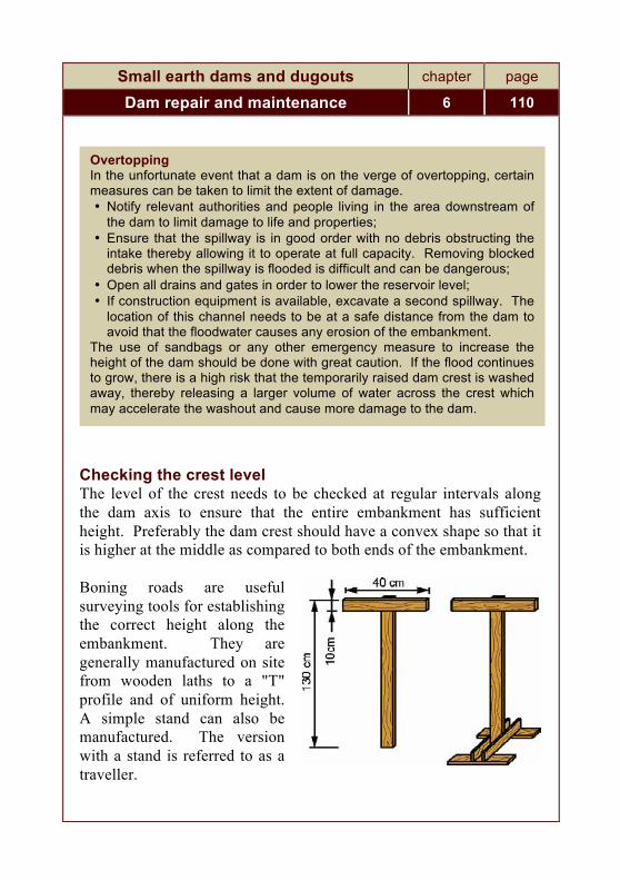
Small earth dams and dugouts chapter page
Dam repair and maintenance 6 110
Checking the crest level The level of the crest needs to be checked at regular intervals along the dam axis to ensure that the entire embankment has sufficient height. Preferably the dam crest should have a convex shape so that it is higher at the middle as compared to both ends of the embankment. Boning roads are useful surveying tools for establishing the correct height along the embankment. They are generally manufactured on site from wooden laths to a "T" profile and of uniform height. A simple stand can also be manufactured. The version with a stand is referred to as a traveller.
Overtopping In the unfortunate event that a dam is on the verge of overtopping, certain measures can be taken to limit the extent of damage. • Notify relevant authorities and people living in the area downstream of
the dam to limit damage to life and properties; • Ensure that the spillway is in good order with no debris obstructing the
intake thereby allowing it to operate at full capacity. Removing blocked debris when the spillway is flooded is difficult and can be dangerous;
• Open all drains and gates in order to lower the reservoir level; • If construction equipment is available, excavate a second spillway. The
location of this channel needs to be at a safe distance from the dam to avoid that the floodwater causes any erosion of the embankment.
The use of sandbags or any other emergency measure to increase the height of the dam should be done with great caution. If the flood continues to grow, there is a high risk that the temporarily raised dam crest is washed away, thereby releasing a larger volume of water across the crest which may accelerate the washout and cause more damage to the dam.

Small earth dams and dugouts chapter page
Dam repair and maintenance 6 111
Boning rods are used to establish additional levels between fixed levels (interpolation) or beyond (extrapolation). It is a quick and inexpensive method for checking levels on surfaces and the depth of trenches. In the figure below, it can be seen that the crest level at point 3 of an embankment is lower than at locations 1 and 2. The levels at points 1 and 2 can be established by using already existing benchmarks or by using the crest level of the spillway. Transferring the correct level to the points 1 and 2 can be done using a tube level or a leveller. By raising the middle boning rod, the bottom end of this rod will indicate the correct level in order to achieve a uniform level between points 1 and 2. Equally, the boning rods can be used in order to create a convex shape of the crest.
Checking the level of the dam crest The same exercise can also be carried out using profile boards. Often, a single boning rod is then used to check the surface levels between the profile boards. This method is commonly applied to secure the correct levels of earthworks layers when building up fills.

Small earth dams and dugouts chapter page
Dam repair and maintenance 6 112
Cracks Settlement can also occur in an irregular way referred to as “differential settlement”. The main reason for this is varying shear forces in the embankment due to different loads exerted on the earth fill. The higher fills in the middle of the dam will settle more than at each end of the embankment, which may cause transverse cracks through the embankment. These cracks and fissures allow water to enter the embankment and provide channels for water leakage.
Differential settlement
Cracks parallel to the dam axis may be caused by varying degrees of compaction in the different zones of the dam. Longitudinal cracks may also be an indication of an emerging slip on the embankment slopes.
Longitudinal cracks

Small earth dams and dugouts chapter page
Dam repair and maintenance 6 113
The best remedy against these problems is obviously to provide good quality compaction at the time when the embankment is constructed. Cracks both perpendicular and parallel to the dam axis can lead to serious damage, however, cracks crossing the embankment are obviously of more concern as it may lead water through the dam and cause a complete washout of the dam. Cracks should be sealed with compacted clay as soon as possible and monitored over time to see if they continue to grow. In order to gain access with compaction equipment the voids need to be widened. The most appropriate equipment for this purpose would be tampers or hand rammers. The seal prevents surface water from entering the embankment and avoids the soils becoming saturated with water thereby reducing its strength. Saturated soils reduce the stability of the embankment slopes and can trigger slides. Major settlements and cracks in the embankment may indicate serious problems with the embankment. Although remedial action such as filling cracks can be carried out straight away, it is useful to consult an experienced dam engineer to establish the full extent and nature of the problem and on this basis determine the most appropriate remedial action. 6.2 Seepage control There is always some seepage through and under an earth dam. Up to a certain limit, the dam can handle this seepage. With the correct design and proper construction, the seepage can be kept at a minimum and cause no damage.

Small earth dams and dugouts chapter page
Dam repair and maintenance 6 114
Excessive seepage causes the washing out of fine particles in the embankment or the foundation eventually eroding the soil in its path. The erosion starts on the downstream side of the embankment and gradually works its way back towards the reservoir, resulting in a pipe through which increased seepage takes place. The seepage can emerge on the downstream slope, the downstream side of the abutments or at the foot of the dam. These are obviously areas warranting particular attention during dam inspections. At first the seepage may appear as moist soils leading to more lush vegetation in the locations where the water exits. If the seepage increases, it turns into wet surfaces and eventually as a flowing spring. Severe piping is recognised when muddy or discoloured water is discharged and creating sinkholes on or near the embankment. Due to the high flow of water, severe piping may cause whirlpools in the reservoir surface, at which time serious damage has already been done to the dam with a high chance of dam failure.
Seepage can also trigger slope failure by saturating the soils and thereby reducing the slope stability. Failing slopes due to saturated soils can therefore be an indicator of excessive seepage. Regular and close inspection of seepage at the base of the downstream slope will detect whether there is a substantial increase in leakage in the course of

Small earth dams and dugouts chapter page
Dam repair and maintenance 6 115
time, indicating whether piping may occur. Excessive seepage is difficult to correct and precautions are best taken during the design and construction stage. One option to reduce the seepage under the dam is to place a clay blanket at the bottom of the reservoir upstream from the dam and extend it up the slope over a limited distance (≈ H/3). This work can be done only once the reservoir has dried up.
Upstream clay blanket to counter seepage
Another solution, complementary to the first, consists of placing a drainage trench at the base of the downstream slope of the embankment. A one metre deep trench is excavated and filled with a sand and gravel filter. The filter stops the loss of fines resulting from the increased seepage and the gravel trench discharges the water in a controlled manner.
Downstream drain

Small earth dams and dugouts chapter page
Dam repair and maintenance 6 116
Alternatively, a weighted filter can be placed at the foot of the downstream slope. This berm at the toe of the embankment consists of a layer of gravel and sand acting as a filter weighted down with a free draining layer of rock placed on top of the filter. The purpose of this berm is once again to stop the loss of soil particles while still allowing the water to exit.
Downstream berm
This solution can also be a viable emergency measure to stop piping which has still not developed all the way through the embankment reaching the reservoir. 6.3 Sliding Sections that are too steep and waterlogged can slide. The soil can become waterlogged as a result of cracks allowing surface water to enter the earth fill or from excessive seepage. Non-cohesive soils have a higher risk of sliding than well-graded materials. Sliding can take place on both the upstream and downstream sides of the embankment.

Small earth dams and dugouts chapter page
Dam repair and maintenance 6 117
Sliding After sliding, the section will have a steeper gradient at the summit and an accumulation of earth at the base. The steeper section will run the risk of further slips. The slide also results in a narrower embankment, which in combination with seepage increases the risk of a dam breach. On the upstream side, the steeper section is also at risk of increased erosion from wave action. During the dry season, the slopes can be strengthened by constructing a berm at the base, which helps to decrease the average gradient. Repair works on the upstream side however can only be corrected by lowering the water level in the reservoir. The repair of slides is a major earthworks operation. The collapsed soils need to be removed in order to reach the undamaged part of the embankment where the soils remain firm. In addition, a stable foundation needs to be excavated onto which the new slope can be built. The slope should be rebuilt to its former shape, preferably with a gentler slope or with a berm. The new fill material needs to be properly compacted and keyed into the existing part of the dam.

Small earth dams and dugouts chapter page
Dam repair and maintenance 6 118
Stabilising a slope with a berm
Building a proper berm on the upstream side of the embankment essentially implies that the reservoir needs to be drained in order to access the damaged area. Before this takes place, it is possible to carry out some temporary repair works while there is still water in the reservoir. One approach is to dump rock at the damaged area in order to form a stable base up to a level above the current water level. This new base can then be topped up with additional material above the water level in order to reinstate the full width of the embankment where the slide took place.

Small earth dams and dugouts chapter page
Dam repair and maintenance 6 119
6.4 Repairing a dam break 6.4.1 Damage assessment Before commencing any repair works to a breached dam, it is important to establish the exact cause of the failure. There are enough examples of dams being repaired and being breached again. It is therefore important to establish the exact cause or combination of reasons why a particular dam failed. Damage assessments are often carried out some time after the dam broke at which time it is more difficult to establish the exact causes of the failure. When the embankment is no longer retaining any water, it is obviously more difficult to determine the reasons for its poor performance. For this reason, it is useful to carry out regular inspections of the dam

Small earth dams and dugouts chapter page
Dam repair and maintenance 6 120
when it is still in operation and to keep records of its performance. A monitoring system in which local villagers are involved in observing the performance of the dam could also provide clues to its failure. Past monitoring and inspection of dams can provide valuable information as to why a dam has failed. Without much information about past performance of a dam, it is still necessary to carry out a proper investigation in order to find out what were the possible causes of the dam breach. Inspection of the remaining embankment can provide some clues. Equally, discussions with local villagers may provide essential information relating to the nature of the failure and also reveal some tell-tale signs indicating plausible reasons for the dam failure. Some villagers may also have participated in the construction of the dam and can describe the work methods applied during the building works – or previous repair works. (i) Inadequate capacity of spillway Unfortunately, this is a common reason for dams overflowing. Many spillways have been designed with insufficient capacity to deal with freak floods. Any obstructions caused by debris will obviously exacerbate the problem. Through discussions with local villagers, it is possible to establish the highest water levels during the floods which caused the damages to the dam. From this information, it is possible to estimate whether the spillway had sufficient capacity.
(ii) Blocked spillway Debris left at a blocked spillway is obviously a good indicator of the reason why a dam overflowed. Accounts from local villagers on the performance of the spillway would also be relevant in this respect.
(iii) Seepage The extent of seepage is difficult to establish after a dam is no longer retaining any water. It is however possible to obtain some information from local villagers on the extent of seepage. Local farmers may have used the seepage for watering gardens established immediately

Small earth dams and dugouts chapter page
Dam repair and maintenance 6 121
downstream of the embankment. The vegetation on the downstream slope of the remaining part of the embankment may also be an indicator.
(iv) Burrows Animal burrows may on their own, or in combination with seepage problems, be the cause of a dam breach. For this reason it is useful to inspect the remaining parts of the dam for similar problems.
(v) Roots from trees Equally, decaying roots from trees may have caused passages for water and combined with other seepage problems accelerated piping problems, leading to a dam breach. The extent to which there are trees and large bushes growing on the remaining parts of the embankment is an indicator whether this is a likely reason for the dam failure. (vi) Settlements A dam breach may have started as a result of the dam overtopping due to excessive floods. If the spillway could not cater for the high amounts of water, floods would overtop the crest. If the dam had a particular section with excessive settlements, the overtopping would be concentrated to this area of the embankment, where the crest would be eroded and eventually result in a wash out. This chain of events can normally be established by checking the level of the remaining crest. If it appears that the area of the breach is much lower than the rest of the embankment, it is likely that the overflow has been concentrated to a short section and thereby caused extensive erosion that developed into a washout. If the dam crest had been at a similar level across the embankment, the risk of a washout would have been reduced, as the water topping over the dam would have been more evenly distributed and less intense.
(vii) Cracks Cracks in the dam may have a similar effect in periods with high water levels and combined with settlements may have concentrated the flow

Small earth dams and dugouts chapter page
Dam repair and maintenance 6 122
of water across the embankment. For this reason, it is useful to inspect the remaining parts of the dam for any additional cracks.
(viii) Slides Whether slides contributed to a dam breach can be established by talking to local villagers. They should be able to inform whether the embankment crest had a uniform width or whether the section of the crest where the breach took place had a narrower width before the failure. Slides at other parts of the dam would of course indicate the need for improved slope protection.
(ix) Poor compaction If a dam was built with insufficient compaction of soils, this problem may be apparent from inspecting the remaining parts of the embankment. Probably, the breach is located in the part where the soils had the poorest compaction works. Villagers who observed the construction works should be able to tell what kind of compaction methods were applied. Equally, they should know whether any water was provided to achieve optimal moisture contents during compaction. (x) Inadequate soils The quality of soils used in the dam can be assessed by examining the remaining embankment and also the old borrow pits. Poor soils may not have been the sole reason for the failure, however, in combination with other problems, it may have contributed to the final damages. The use of poorly graded soils with high contents of silt or clay or use of clay with highly expansive properties may have been a contributing factor to the dam failure.
Finally, it should be stressed that once a dam has been repaired, it is important to closely monitor its performance when the reservoir is re-filled. As the repair work mainly focus on the damaged sections, there are still many unknowns relating the to the performance of the old sections of the dam. Equally, the performance of the repaired section needs to be closely watched, similar to when building a new dam.

Small earth dams and dugouts chapter page
Dam repair and maintenance 6 123
6.4.2 Filling the breach In the unfortunate event that a dam breaks, repair works need to be carried out using sound construction procedures to ensure that the failure is not repeated. It should be acknowledged that many dams have been built with limited technical guidance. When a dam is restored or rehabilitated, ensure that adequate technical expertise is obtained providing expert guidance on how to rehabilitate the dam to a standard which has a better chance of survival. At the same time as rebuilding the embankment, it is useful to make an overall assessment of the condition of the dam and also consider other corrective measures. This may involve additional activities in addition to plugging the hole in the embankment. Perhaps measures are also required to deal with seepage, settlements, structural defects or improving the spillway. As the water supply has already been disrupted, this is an appropriate time to deal with any additional defects of the dam and taking appropriate corrective action. Due to the breach, the reservoir is empty thus allowing for repair works to take place on the upstream side of the embankment and the dam intake. It is also a good opportunity to repair or install proper dam intakes. Plan the repair work to commence at the start of the dry season, thereby allowing for sufficient time to complete works before the next rainy season arrive. Before commencing the fill works, the breached area of the dam first needs to be cleared of all loose soils and debris. Excavate all loose soils down to the part of the dam still consisting of firm and compacted soil. If the dam has a core, re-establish the extent of the core material. Cut back the sides of the breach to a relatively gentle slope, preferably to a gradient of 1:3. This will ensure that most of the destabilised section is removed and also provides better access to the

Small earth dams and dugouts chapter page
Dam repair and maintenance 6 124
work site. Workers, equipment and material supply can then access from the crest rather than climbing up the embankment slope.
Clearing a dam breach
Excavate a cut-off trench to ensure that the filled breach is well keyed into the ground thereby reducing any seepage under the dam. Extend the trench up the breach sides in order to reduce any seepage in the joints between the old and the new dam section.
Key trench The earthworks need to follow similar construction standards as when building a new dam. New soils with the appropriate properties need to

Small earth dams and dugouts chapter page
Dam repair and maintenance 6 125
be sourced and should be spread in layers and properly compacted at optimal moisture content. If a core is installed, it should be built up in layers at the same pace as the surrounding fill. The layers should be cut in steps where the new fill meets the breach sides - in a similar fashion as when expanding an earth fill, thereby securing a tight bond between the old and new dam sections and avoiding that the joints do not become conduits for seepage or a potential slip surface.
Building the filled breach in layers Rather than rushing off to plug the breach, organise the work applying quality work methods, ensuring that the repaired section is properly keyed into the old sections, and thereby achieving joints and a new section which at least is of equal quality if not better than the old dam. This approach reduces the risk of having to return to deal with a new dam breach in the same location. Once a major repair has been completed, it is important to closely monitor the performance of the dam when the reservoir is filled. When filling the reservoir, water will once again soak the old and new sections of the embankment and cause further settlements. A gradual filling of the reservoir allows this process to take place in a controlled

Small earth dams and dugouts chapter page
Dam repair and maintenance 6 126
manner during which period the dam can be closely monitored to assess the effectiveness of the repairs. For this reason, it is also recommended to keep the reservoir below the maximum level during the first year. For the same reasons, avoid rapid filling and emptying of the dam, allowing the new embankment fill to first settle properly. 6.5 Maintenance of slopes The most effective maintenance measures depend on the type of slope protection used. Each year, any erosion gullies on unprotected slopes due to rainwater run-off need to be filled up with earth or gravel. If there is too much erosion, a general protective layer of gravel or stone can be used. Another method for limiting the development of gullies consists of constructing a series of small horizontal terraces on the slope.
Terracing to protect slopes

Small earth dams and dugouts chapter page
Dam repair and maintenance 6 127
All trees and shrubs growing on the embankment should be regularly uprooted. Vegetation should never be allowed to grow to the size of trees on the embankment. However, if a tree is encountered on the embankment of an old dam, which was not properly maintained, uprooting it may cause more harm than good since the resulting holes or rotting roots may further weaken the embankment.
The grass on slopes should be cut every year, after it has produced seeds for re-grassing. Small trees and shrubs can be uprooted at the same time. Keeping the grass short and removing shrubs provides a tidy surface which can easily be inspected for structural problems or possible seepage.

Small earth dams and dugouts chapter page
Dam repair and maintenance 6 128
Slopes protected with gravel or stone rip-rap need to be inspected every year to check whether material has been washed away, requiring some replacement. 6.6 Burrowing animals Burrowing animals can also cause trouble for an embankment dam. Checking for burrows should be part of the regular inspection of the dam. Any burrows found in the embankment need to be filled as soon as possible Rodents, rabbits and crocodiles are known to create burrows in dam embankments. Burrows may be created both on the upstream and downstream side of the embankment. During high water levels, the burrows are filled with water and as a result compromise the water retaining capacity of the embankment. Burrows can substantially reduce already existing leakage paths, thus increasing the risk of piping failure. If the burrows are not too deep, they can be filled by first excavating the material above the burrow and then filling the void with soil compacted in layers. Alternatively, the burrow entrance can be filled with a soil and cement slurry which is poured into the borrow using a large size pipe (more than four inches).

Small earth dams and dugouts chapter page
Dam repair and maintenance 6 129
Burrows causing increased seepage
Placing stone rip-rap or cement-based masonry on the surface may reduce future burrowing activities. 6.7 Maintaining the crest The crest of the embankment needs to be maintained at the originally planned height and shape in order to secure the necessary freeboard and thereby avoid any risk of water overtopping the dam. Similar to the downstream slope, appropriate measures should be taken to avoid any water entering the earth fill and to avoid any erosion of the surface of the crest.

Small earth dams and dugouts chapter page
Dam repair and maintenance 6 130
Drainage on the crest surface is easily arranged by providing a 5 percent cross slope, thereby leading rainwater into the reservoir. Planting grass on this surface increases its strength and reduces erosion. If there is any traffic on the crest, it may be useful to place a 10 cm layer of gravel to protect its surface. Well-graded and compacted gravel also acts as an excellent seal, preventing erosion and any rainwater entering the dam body through the crest. 6.8 Maintenance of ancillary structures
6.8.1 Intake structure
Branches, floating objects or sediments deposited on the reservoir bottom can obstruct the entrance to the intake.
The entrance to the strainer or a perforated intake pipe should be cleared and cleaned whenever possible, and particularly if there is a drop in the water pressure at the draw-off.
Remember that the intake should be located somewhat higher than the lowest point of the reservoir bottom to allow for the inevitable deposit of sediments carried into the reservoir by the river flow or by erosion in the catchment area. 6.8.2 Spillway A blocked or improperly functioning spillway is a common cause of damage to both the spillway and the dam itself. If sufficient water cannot exit through the spillway there is a risk of both overtopping of the spillway and the embankment, causing serious damage to both. The spillway therefore needs to be inspected on a regular basis.

Small earth dams and dugouts chapter page
Dam repair and maintenance 6 131
Remove any floating objects or branches in the vicinity of the inlet which could get jammed and block the spillway. Any debris at the inlet should be cleared as soon as possible. The spillway channel and outlet should be checked for possible erosion after each time water has passed through. All possible scouring at the downstream part of the weir or sills should be prevented. It can be corrected by placing stone rip-rap, gabions or other types of protection. Planting and maintaining grass on the channel surfaces may be a sufficient measure to control erosion. Any scouring of the channel and its outlet indicates that the surface in the channel is not sufficiently strong to resist the flow of water. This may indicate the need for more drop structures and a stronger channel surface. Alternatively, it may be possible to widen the channel, thereby reducing the flow intensity. A too narrow spillway is a common reason for major problems with spillways and can also lead to overtopping of the channel as well as the dam embankment. A too wide channel will never be a problem. Estimating the required capacity of the spillway is often a difficult task. Runoff characteristics in the catchment area may have been under-estimated when the dam was built or it may have changed during the lifetime of the dam. Considering the importance of the spillway for the safety of the dam, it is therefore crucial that serious attention is also given to the adequacy of the spillway when planning and carrying out major dam repairs. Equally, during maintenance and operation of a dam, the spillway needs due attention.

Small earth dams and dugouts chapter page
Dam repair and maintenance 6 132
6.9 Silting of reservoir It is often the case that erosion in the catchment area over the years silts up the reservoir more quickly than expected, with a consequent loss of storage capacity. This is a common feature in arid and semi-arid areas. There are two methods to rectify this situation.48 First, the reservoir can be dredged, i.e. the accumulated silt is excavated and removed. This requires that the reservoir is drained for the period of time when the works take place, leaving the users of the dam without their regular source of water. Dredging is also a large civil works endeavour, which not only involves excavating the silt. The removed soils needs to be transported away from the reservoir and securely placed in a location where there is no risk that it returns into the waterways or causes new silting problems. For the above reasons, dredging is in most cases not a feasible option for valley dams.49 Instead, the preferred option is often to raise the embankment, provided that the riverbanks are high enough. This option does however also has its drawbacks as the raised reservoir will lead to new areas being flooded in the catchment area. This solution is in most cases cheaper as it involves less earth moving. Leaving the accumulated silt in the reservoir also reduces potential environmental problems. When increasing the size and height of an embankment, the existing surfaces is first cleared and stripped on the crest and downstream sides. Equally, the area for the extended dam base needs to be cleared.
48 The best way to fight siltation of the reservoir is to decrease the erosion in
the catchment area by a soil and water conservation programme. 49 De-silting is however commonly carried out for smaller water storage
facilities such as ponds and dugouts.

Small earth dams and dugouts chapter page
Dam repair and maintenance 6 133
Raising the embankment
From the downstream base, fill material is placed in layers watered and compacted. When extending the width on an embankment, it is important that a good bond is achieved between the old and the new parts of the embankment. The new layers therefore need to be keyed into the existing embankment as show in the figure below. Equally, it is important that the new fill is compacted properly to avoid any partial settlement which may lead to longitudinal cracks and potential slip surfaces.
Widening an embankment

Small earth dams and dugouts chapter page
Dam repair and maintenance 6 134
The spillway crest has to be increased by the same height. To do so, a weir can be constructed in the open channel of a side spillway. 6.10 Catchment protection Protecting the reservoir against silting is important in order to ensure that the newly acquired water source may benefit the local community for a long period of time. Silting of the reservoir is caused by poor land management in the catchment area such as extensive farming activities close to the reservoir or soil erosion taking place in the rivers and streams supplying the dam with water. Remedial measures dealing with silting of a reservoir is a major undertaking. To restore the capacity of the dam, there are essentially only two options, either removing the silt by dredging the reservoir or by building a higher dam. Both solutions are expensive and due to this, dams are often abandoned when the silt has filled the reservoir.

Small earth dams and dugouts chapter page
Dam repair and maintenance 6 135
The best approach is therefore to take preventive action to reduce the amount of silt entering the reservoir. A number of these measures are inexpensive, basically related to good management of the land areas surrounding the dam. Other measures such as reducing soil erosion in streams and rivers can be carried out as part of the original dam construction project. 6.10.1 Farming activities Farming activities close to the reservoir is often a common cause of siltation. With a regular supply of water from the dam, farmers are tempted to start or increase farming activities in the catchment area and in particular close to the banks of the reservoir. When this takes place, it is important to provide guidance to the communities on how soil erosion can be minimized, thereby reducing the about of silt entering the reservoir. The catchment area is often used for farming activities both before and after a dam has been constructed. Ploughing of soils can cause excessive soil erosion increasing the silt entering the reservoir. Soil tilling activities should therefore be banned in the immediate vicinity of the reservoir. A buffer area along the reservoir banks with healthy vegetation and can act good barrier against silt entering into the dam. Siltation can also be reduced by ploughing in parallel to the contour lines, thereby retaining more of the surface water. Equally, terracing and drainage running parallel with the contour lines will limit soil erosion. Planting trees along the contour lines or establishing forests in the catchment area reduces the amount of surface water entering the reservoir. It also reduces the intensity of the flow of water to the reservoir. Trees also act as an effective windbreaker, reducing wind erosion of bare lands, and decrease the amount of water evaporating

Small earth dams and dugouts chapter page
Dam repair and maintenance 6 136
from the reservoir. Planting fruit trees or establishing wood lots can be a viable alternative income for farmers owning land in this area. Dams are often a source of water for livestock. Domestic animals have a tendency to remove all surface vegetation in the surrounding areas where they obtain drinking water. Rather than leading the animals to the shore of the dam, watering troughs should be build downstream of the dam, thereby reducing animal traffic in the catchment area. 6.10.2 Soil protection Terracing In the catchment area, the land areas are sloping towards the reservoir. Surface water during rains may cause some erosion and carry silt to the reservoir. Steeper gradients and areas that are not properly vegetated are more prone to erosion. Areas that are farmed and ploughed on a regular basis have a higher risk of erosion. A common solution to limit soil erosion is to build terraces in the areas where there is a risk of soil erosion. With less steep gradients the water flow is slowed down and less silt is carried away. Catch-dams Catch-dams are commonly used to limit the amount of silt entering dugouts. These can also be used on seasonal streams containing high amounts of silt before the water reaches the reservoir. Catch-dams need regular maintenance. The accumulated silt needs to be removed and disposed of in a safe place on a regular basis in order to make sure the catch-dam is functioning properly. The silt can be used for fertilizing vegetable gardens. Weirs Building weirs in eroded gullies can be an effective method of reducing erosion in small rivers and streams. The weirs reduce the

Small earth dams and dugouts chapter page
Dam repair and maintenance 6 137
longitudinal gradient in the riverbeds and thereby decrease the amount of silt carried by the water. Weirs are commonly built with stone placed on the gully bed. In general, the height of these dams is one metre or less. The weir should measure at least 50cm in width at the top, sloping down at an angle to its base (maximum 1:1). A buttress of earth is placed against the uphill side of the wall, thus ensuring greater water tightness.
Weir
Weir construction is often combined with planting of grass and bushes on the sides of gullies and streams to further reduce soil erosion. Scour checks Scour checks are commonly used in road drains for the same purpose as weirs. They can also be used on drainage ditches in farmlands to reduce the speed of water and thus decrease its silt content. Scour checks can be built using stone or wood.

Small earth dams and dugouts chapter page
Dam repair and maintenance 6 138
Scour checks
The frequency of the scour checks depends on the gradient of the drain. The appropriate distance between the scour checks are shown in the adjacent table. Water from roads Excavated cuts and fills along the road line can trigger increased soil erosion in areas where non-cohesive soils are prevalent. Side slopes on cuts and fills should therefore be stabilised using similar methods as applied on the downstream dam embankment. Equally, water from the drainage systems on local roads can be a major cause of erosion. Road drainage systems often concentrate the flow of water at outlets from drains and culverts. Such outlets need to be carefully located and designed to avoid triggering soil erosion, which may contribute to the siltation of dam reservoirs.
Gradient of drain [%]
Scour check interval [m]
4 not required 5 20 6 15 7 10 8 8 9 7
10 6

Small earth dams and dugouts chapter page
Dam repair and maintenance 6 139
6.10.3 Hygiene Keeping animals away at a distance from the reservoir is also a hygienic issue. Water from dams is commonly used for household purposes so it is important to avoid having animals and humans defecating near the reservoir, and also avoid such waste being transported to the dam during rains. The preferred solution to these concerns is to provide access to the water for household purposes and livestock downstream of the dam. If water is pumped to communities situated in the catchment area, it is important to make arrangements so that wastewater does not return to the reservoir. Water from washing can be used for garden plots. Equally, excess water from stand pipes and cattle troughs can be used for such purposes. Rural communities are often not adequately equipped with latrines, with the result that people often relieve themselves behind bushes. Human excrements left on the surface may be washed into the reservoir during rains, where germs and pathogens may be stored and cause transmission of water-borne diseases. For this reason, it is important that there are sufficient latrines accessible to all inhabitants living in a catchment area. Equally, public facilities such as schools, clinics and markets need similar facilities. The latrines should be located at a safe distance from the reservoir banks (at their highest flood levels).

Small earth dams and dugouts chapter page
Dam repair and maintenance 6 140
6.11 Monitoring and inspection Similar to other types of infrastructure, dams and dugouts are in need of regular maintenance in order to protect the investments carried out during the initial construction stage. After all, the main benefits from the construction of water harvesting structures are accrued through a long-term operation of the facilities. To achieve this, there is a need for continuous follow-up after the construction stage during which the performance of the dam is monitored and when required provided essential maintenance and repair. As shown earlier in this chapter, dams and its ancillary structures are prone to wear and tear and therefore need maintenance and repair works at regular intervals. The exact nature of the maintenance works is dependent on the damages occurring on the dam. For this reason, the dams and all their components require regular monitoring and inspection in order to assess their performance and detect any damages. Furthermore, if damages can be detected at an early stage before they become critical to the performance of the dam, the required repair inputs may remain limited in size and technical complexity and can often be carried out without disrupting the operation of the dam. Inspection and monitoring of dams needs to be carried out in close collaboration with the users of the dam. Maintenance works may have to be fully financed by the users of the reservoir and for this reason it is important that they are actively involved in the monitoring of the performance of the dam. Regular monitoring of the dam can be organised through a village committee. However, if major changes are observed in regards to the performance of the dam, the users need to be able to contact relevant technical authorities in order to obtain guidance on appropriate remedial measures. If the problems appear to be serious, it may be necessary for technical staff to immediately carry out a field

Small earth dams and dugouts chapter page
Dam repair and maintenance 6 141
inspection. For this to take place at the right time, it is important to establish proper communication lines between the local users, its management committee and the relevant technical authorities. It is useful for the village dam committee to keep a logbook in which any observations as well as instructions from technical staff are recorded. When technical staff returns to the site, the earlier recommendations can be reviewed and any follow-up action can be discussed on the basis of the results of earlier advice. Still, with a local monitoring system established, it is important that technical staff visit the facilities on a regular basis. Such visits are not only useful for ensuring that the dam is in good order, but is also a good opportunity for providing advice and guidance on maintenance and operation of the dam. The following tables summarise the most common items to look out for during a dam inspection. Carrying out the inspection and recording the observations made should be carried out together with members from the village dam committee. Their close involvement in this process improves their understanding of proper operation and maintenance of the dam. When problems are discovered, these need to be closely explained to the local users. When repairs are required the best solutions are normally the ones that rely on local inputs. Provision of external inputs may take longer time during which the observed deficiencies may grow into critical problems.

Small earth dams and dugouts chapter page
Dam repair and maintenance 6 142
Dam Inspection
Name of dam:
Location:
Inspector(s): Date:
Condition/ problem observed Observations Remedial action
Ups
tream
slo
pe surface protection
beaching, slides, cracks
erosion
animal burrows
Cre
st
ruts, potholes, edge erosion
insufficient cross slope
settlement
cracks
trees and bushes
Dow
nstre
am s
lope
erosion
slides, cracks
seepage or wet surface
animal burrows
trees and bushes
Toe
and
dow
n-st
ream
are
a
cracks, slumps
wet surface, seepage, boils
erosion
trees and bushes
Abut
men
ts erosion, scouring
seepage, wet surface
slides, cracks
Additional comments:

Small earth dams and dugouts chapter page
Dam repair and maintenance 6 143
Inspection of spillway and other components
Name of dam:
Location:
Inspector(s): Date:
Condition/ problem observed Observations Remedial action
Spillw
ay
inle
t
debris and vegetation
cracks
erosion
Spillw
ay c
anal
debris and vegetation
erosion/scouring
cracks
insufficient capacity
Stilli
ng b
asin
, sp
illway
out
let debris and vegetation
erosion/scouring
undercutting
cracks
Inle
t, ou
tlet
Wat
ersh
ed erosion, scouring
animals
farming activities
Additional comments:

Small earth dams and dugouts chapter page
Dam repair and maintenance 6 144
6.12 Community involvement Land usage The construction of a dam requires large land areas where the dam and its reservoir will be located. This implies that major changes will take place in the usage of the land areas in the catchment area of the dam, which in the past may have been used for farming or grazing purposes. When embarking on a dam project intended for the inhabitants of nearby communities, it is obviously important to ensure that they are in full support of such an initiative and that they are properly informed about the future changes to the land usage. Some members of the community may loose major portions of their land holdings as a result of such a development project, and therefore needs to be compensated for such losses. This is not only important for farmers with clear ownership titles of land but also applies to users of leased or communal lands. The issue of land compensation can be a long and tedious process but needs to be addressed in a proper manner so all affected parties actually see a net benefit from the planned scheme. During the planning stage, it is also important to raise awareness about future land management in the areas surrounding the reservoir. To reduce siltation, the communities need to agree to certain farming and grazing practices which limits soil erosion in the catchment area. Involvement during construction and maintenance The use of labour-based construction methods provides increased employment opportunities in particular during the construction of the dam. Equally, the areas intended for the reservoir need to be cleared for bush and trees before the dam is filled – thus providing additional employment. When recruiting workers for these purposes, preference is normally given to the nearby communities benefiting from the improved water source.

Small earth dams and dugouts chapter page
Dam repair and maintenance 6 145
Once the dam is in operation, there is a need for regular maintenance. Again, the best solution is to source labour for such work from the local communities. Clear conditions of employment When recruiting the workforce, it is important to brief them in advance of the employment conditions, including hours of work, remuneration, pay days, the use of task work, who is in charge of supervision, etc. Giving advance notice of the employment opportunities allows people to rearrange their normal chores and work tasks so they are available for work on the dam. Paid work Community development schemes are commonly designed with certain levels of contributions from the beneficiaries. It is often argued that such inputs strengthen the ownership of the project. Whether this is the case or not in each individual project, it is important that such contributions are equally leveraged on all the beneficiaries. A common approach is to ask the poorest to contribute with free labour. When schemes target a larger group of beneficiaries, there is a risk that poor members of the community ends up taking a larger burden of such contributions. It is important to bear in mind that the poorest families may not necessarily have any free labour to spare. Equally, it should be acknowledged that the use of unpaid labour does not yield similar work outputs as when the workforce is paid a decent salary. The issue of community contributions through their labour inputs is an equally important issue both during the construction and the operation stages. During the construction stage, there is often funding from outside, i.e. central or provincial government, donors or NGOs. However during the maintenance and operation of the completed scheme, there is very seldom any external financial support, so any repairs and maintenance needs to be funded from local sources.

Small earth dams and dugouts chapter page
Dam repair and maintenance 6 146
Rather than relying on voluntary labour, it is better to recruit paid worker for maintenance, financed through user fees.50 Water usage If a single user owns a water scheme, such as a borehole or a dugout, it is easy to regulate the water usage and also to deal with maintenance issues. When the water supply scheme is benefitting one or several communities with different types of water needs, its management becomes more complicated. Water is a limited resource and its use needs to first give priority to the basic needs of the households. Any remaining surplus can then be used for commercial activities such as livestock, vegetable gardens, irrigation schemes, etc. In any of these scenarios there is a need to regulate the usage. Equally, it is necessary to secure sufficient funding for its maintenance and operation. To address these usage related issues, it is common practice to establish a Water User Committee (WUC). The water user committee is charged with the responsibility to regulate the usage of water in accordance with a set of guidelines (by-laws), which the community has agreed upon. The WUC is often in charge of the collection of water usage fees, using this income for maintaining the water supply scheme. Gender issues Water from dams is commonly used as the prime source of water for households in the vicinity of such schemes. The community will build up a certain reliance on this water source for household and other purposes. Providing a sufficient and continuous supply has a great impact on the livelihood of these households. Its use and distribution
50 In many cases, the term “voluntary labour” is misused in relation to unpaid
workers who have been ordered by local authorities to carry out community work.

Small earth dams and dugouts chapter page
Dam repair and maintenance 6 147
is therefore of great importance to the community to which it is provided. Collecting water for household purposes is often the responsibility of women. Access to clean water has a great impact on the health of the household and in particular the children. This implies that women will often take greater interest in a new water supply scheme. It is therefore important to observe the particular concerns and needs of women when designing and operating a water supply scheme. Ensuring their full participation during the planning and construction stage can therefore build strong ownership into the investments. Equally, it is important that women are well represented in the decision making process for the management and distribution of the water once the scheme is complete and in operation.

SPWP TECHNICAL GUIDE chapter page
Small earth dams and dugouts 7 148
7 Dugouts and hillside dams 7.1 General Schemes for storage of water come in several sizes and designs. The simplest is rainwater harvested from roofs. Another very simple arrangement commonly used in rural areas is hand-dug ponds. More advanced schemes include dugouts, hillside dams, sand dams and small earth dams. Dugouts are traditional, earthen basins used for collecting and storing rainwater from seasonal streams or in depressions in the terrain where surface water tends to collect. In arid areas where there is limited access to groundwater or other water sources, many communities rely on dugouts.
Hillside dams are similar to dugouts, harvesting surface run-off water during the rainy season. Hillside dams and dugouts are very much the same type of structures, the main difference being their location. Both can first be built to a modest size and later on enlarged by deepening the reservoir. As they are simple and inexpensive to construct, these small schemes are commonly used by a single farmer or a small group of users. Due to their simple design, they are easy to maintain. Since they supply water to a small group of users, issues of water distribution and operation are also easier to deal with.

SPWP TECHNICAL GUIDE chapter page
Small earth dams and dugouts 7 149
7.2 Design of hillside dams and dugouts The basic design of a dugout or hillside dam is not too different from harvesting rainwater in man-made ponds. The main storage area consists of the excavated volume similar to digging a pond. As the dugout is located in sloping terrain, the excavated material can be used to increase the water storage capacity by building an embankment at the lower side of the reservoir. Similar to ponds, the main water storage is in the excavated area. The surrounding natural soils, if reasonably impermeable, will contain the water. These in-situ soils are in most cases dense enough to resist the water pressure. As most of the reservoir is under ground level, there is limited pressure on the embankment, thus reducing potential seepage problems. The embankments on dugouts are not as high as on conventional earth dams, normally not exceeding two to three metres. The height of the embankment depends on how deep the dugout is, since all material is sourced from the dugout. Due to the limited size of the embankment, the width of the crest is normally not more than one to two metres. Dugouts are also common in valleys where there is only temporary flow of water in the rainy season. The shape of these dugouts is often similar to small earth dams, essentially building a straight

SPWP TECHNICAL GUIDE chapter page
Small earth dams and dugouts 7 150
embankment crossing the valley or terrain depression. If carefully planned, dugouts and hillside dams can be built in stages, first starting off with a shallow pond. Deeper reservoirs have less evaporation than shallow dams covering a wide surface area. The reservoir can be deepened during the next dry season(s) using the excavated soils to increase the size of the embankment.
Dugout built in stages The rationale for building the dugout in stages is twofold. Dugouts are usually designed to cater for individual farms or a small group of users, relying only on the labour available in these households. The availability of labour is higher in the dry season. The most appropriate time to schedule improvement works to dugouts would be towards the end of the dry season when the water levels are low. Secondly, a gradual construction of the dugout allows for a careful expansion, which can be fine-tuned to the availability of run-off water. The shape of the embankment depends on the local terrain. Some are constructed as a straight embankment blocking a valley or other depressions in the terrain. Embankments for dugouts located in uniform sloping terrain are commonly built as a half circle as shown below.

SPWP TECHNICAL GUIDE chapter page
Small earth dams and dugouts 7 151
7.3 Location The best location for both dugouts and hillside dams are at places where surface water tend to collect during rains. These can be gullies, dry riverbeds and similar shape depressions. The soils at this location should contain a certain amount of clay to avoid excessive seepage. Areas with predominantly sandy soils should be avoided since such soils will not retain the water. During site investigations, it is useful to dig a test pit to ensure that there are no strata of sandy soils below the surface. 7.4 Silt traps Dugouts harvest surface water that may contain a considerable amount of silt. For this reason, it is useful to build silt traps thereby avoiding that the silt reaches the reservoir. The silt traps are excavated upstream of the dugout to a depth of approximately one metre at locations as shown below.

SPWP TECHNICAL GUIDE chapter page
Small earth dams and dugouts 7 152
To further reduce the siltation, the channel entering the reservoir can be constructed with a series of sills thereby reducing the speed of the water entering the reservoir. This measure counters any erosion in the entry channel. 7.5 Spillways Similar to small earth dams, dugouts also need spillways with adequate design and capacity to direct excess water away in a safe manner avoiding any damage to the embankment. Some dugouts are built adjacent to roads, using road embankments to retain water. When road fills are used for retaining water, it is important that adequate cross drainage is provided to the road to avoid floodwater from crossing the road surface. 7.6 Construction Before commencing the excavation works, the exact location of the dugout needs to be set out. Similar to a small earth dam the base of the embankment needs to be set out in detail. The two ends of the embankment should be at the same level. As the terrain is sloping, the exact position can be determined using a tube level.

SPWP TECHNICAL GUIDE chapter page
Small earth dams and dugouts 7 153
The centre of the pond is located at the middle between the two end points of the embankment. If the embankment is shaped as a semi-circle, it can be set out by placing a peg at the centre of the pond and using a string line with a fixed distance to set out the toe of the embankment fill. The width of the base of the fill depends on the height of the fill at any given place along the embankment. With a 1:2 slope on the upstream side and a 1:1.5 slope on the downstream side, the width of the embankment at its base is:
W = C + H x 2 + H x 1.5 = C + 3.5H
where C is the crest width and H is the embankment height. Leave a distance of two to three metres between the pond and the foot of the embankment. This buffer improves the stability of the pond walls. It also keeps the embankment at a safe distance in case there is any erosion of the walls of the pond. The walls of the pond should be excavated at a maximum slope of 1:2. Any steeper gradient may cause erosion or slides when the pond is filled with water. Dugouts and hillside dams are often excavated by hand during the dry season. They can be built over several years, gradually increasing the size of the pond. The pond does not necessarily need to be excavated to full depth during the first dry season. A shallow pond can still be taken into use during the first rainy season. It is however important to create a spillway to avoid excess water spilling over the embankment.

SPWP TECHNICAL GUIDE chapter page
Small earth dams and dugouts 7 154
Dugouts and hillside dams are often built using manual labour only. Some compaction of the embankment can be achieved with hand rammers or by driving a tractor across the fill material. These methods do not provide the same density of materials as when using proper compaction equipment. As a result, the soils in the embankment will have a higher degree of seepage. On the other hand, most of the water is stored in the excavated part of the reservoir where the surrounding soils are well compacted. Over time, the embankment will continue to settle as a result of its own weight and the action of water and become more impermeable. Still, these dams are more permeable than dams constructed using mechanical compaction equipment and for this reason, great care should be taken to avoid overfilling the dam.
7.7 Soil bunds Soil bunds are essentially drains excavated roughly in parallel to the contour lines of the terrain with the purpose of expanding the catchment area from which run-off rainwater is harvested. These catch-water drains are aligned in the terrain so that they provide a longitudinal slope of 2 to 3 percent. A steeper slope increases soil erosion and silting of the pond.
Soil bunds

SPWP TECHNICAL GUIDE chapter page
Small earth dams and dugouts 7 155
The drains are excavated to a depth of about 30 centimetres, placing the soils on the downside of the drain. The surfaces of the bund and the drain itself should be stabilised by planting grass. Keeping the grass short in the drain will improve its performance. Constructing soil bunds parallel to the shores of the reservoir of a small earth dam is also an effective measure to reduce the amount of siltation of such dams.