Embed Size (px)
Citation preview
DOE/WIPP-02-3184
CH Packaging OperationsManual
U.S. Department of Energy
Revision 5
May 2007
This document supersedes DOE/WIPP-02-3184, Revision 4.
DOE/WIPP-02-3184Revision 5
CH Packaging Operations Manual
Approval on File May 2007 Casey Gadbury Date Office Director, Office of the National TRU Program
Processing and final preparation of this paper was performed by Washington TRU Solutions LLC, theWIPP management and operating (M&O) contractor for the Waste Isolation Pilot Plant underU.S. Department of Energy contract number DE-AC29-01AL66444.
DOE/WIPP 02-3184 Rev. 5 Page 3 of 112
This document has been submitted as required to:
Office of Scientific and Technical InformationP.O. Box 62
Oak Ridge, TN 37831(865) 576-8401
Additional Information about this document may be obtained by calling (800) 336-9477. Copies may be obtained by contacting the National Technical Information Service,U.S. Department of Commerce, 5285 Port Royal Road, Springfield, VA 22101.
DOE/WIPP 02-3184 Rev. 5 Page 4 of 112
RECORD OF REVISION
Revision Reason for Revision/Change
0 New CH Packaging Operations Manual. This document supercedesDOE/WIPP 93-1001 and must be used in conjunction with DOE/WIPP 02-3183,CH Packaging Program Guidance, and DOE/WIPP 02-3185, CH PackagingMaintenance Manual.
1 Revisions are as follows:! Update references! Add titles at first reference to tables, figures, sections, subsections, and
new acronyms! Add steps to adapt procedure to new equipment, materials, and processes
such as:
- Installation of bumper pads on drums and SWBs- Verification of He bottles for test- Verification of cotter pin installation in new style pallets
! Add clarifying text to reduce risks of using incorrect equipment, materials,and specifications such as:
- Clarification of procedural compliance- Clarification of packaging position on trailers- Clarification of stuck lid pressurization procedure and diagram of system
! Improve instructions to document actions on attachments! Change format and text to achieve inter- and intradocument consistency! Delete extraneous material or revise text to improve clarity ! Add Subsections 1.2, 1.3, and 1.4 and supporting figures for shipments of
55-gallon, 85-gallon, and 100-gallon drums. Revise other text inSections 1.0 and 2.0 accordingly
! Add explanatory notes and text in Sections 1.0 and 2.0 for operations usingHalfPACT
! Change tolerances for ACGLF CAUTIONs from (+1 degree) to(+2 degrees)
2 Revisions as follows:
! Update references! Provide reference to SWB, TDOP, and CH trailer operations and
maintenance manuals! Clarify the performance of parallel activities! Provide guidance for component inspections! Define "clean" o-rings! Clarify calibration data recording requirements! Clarify leak rate calculation requirements based on post-test conditions! Provide guidance for performing post-test calibration deviation guidance! Require pallet ID and ratchet strap serial numbers to be recorded on
shipping papers
DOE/WIPP 02-3184 Rev. 5 Page 5 of 112
3. Revisions as follows:
! Added a torque value to OCV guide plates.! Added an "or" to the torque paint on Z-flange screws and ICV upper spacer
screws. This will allow the user to check torque if the torque paint was notused.
! Added a note to Subsection 4.3.16 clarifying the values for post-testcalibration deviation.
! Added guidance for drum payload assembly height.! Added notes to allow tape on reinforcing plate tabs.! Deleted specified number of filters installed on SWB/TDOP.! Revised range on pound-inch torque wrench.! Moved step for verification of airflow through ICV/OCV test ports.! Revised note in Section 2.16 regarding WWIS data.! Clarified trailer inspection steps.! Referenced DOE/WIPP 02-3183, Section 4.2.9, for leak test guidance.! Corrected numbering in attachments.
4. Revisions as follows:
! Corrected nomenclature for consistency with the SAR.! Added a precaution in Section 2.1.4 that requires marking devices to
be low in chloride, fluoride, halide, and sulfur content.! Clarified inspection requirements.! Added additional inspection steps at Steps 2.18.1 and 2.34.1.! Added a torque range to Steps 2.7.2 and 2.26.2.! Added following text to Note preceding Step 2.19.7 to state, "If the
total weight of the tractor, trailer, and payload is greater than or equalto 77,500 lb, the shipment should be scaled to ensure the 20,000 lbtrailer axle weight limitation and 80,000 lb gross weight limitation arenot exceeded."
! Revised bullets in Notes before Steps 2.19.1 and 2.35.1 to adjustweight difference from 2,000 lb to 1,000 lb, and to revise table toremove items 2 and 4 and the notation of "Preferred method."
5. Revisions as follows:||
! Changed the inspection and acceptance criteria for upper spacer and|locking Z-flange screws found in Steps 2.7.2, 2.8.2, 2.26.2, and|2.27.2 |
! Changed cover page to indicate new Office Director.|! Added "C of C" (certificate of conformance) to last bullets of|
Steps 4.2.1 and 4.4.1.|! Added "C of C" to Attachment 7, Step 4.2.1; and Attachment 8,|
Step 4.4.1.|
DOE/WIPP 02-3184 Rev. 5 Page 6 of 112
M&O CONTRACTOR TECHNICAL REVIEW ORGANIZATIONS
WASHINGTON TRU SOLUTIONS
CBFO REVIEW ORGANIZATIONS
OFFICE OF THE NATIONAL TRU PROGRAM
QUALITY ASSURANCE
EDITORIAL
DOE/WIPP 02-3184 Rev. 5 Page 7 of 112
TABLE OF CONTENTS
1.0 PAYLOAD PREPARATION . . . . . . . . . . . . . . . . . . . . . . . . . . . . . . . . . . . . . . . . 91.1 Basic Information . . . . . . . . . . . . . . . . . . . . . . . . . . . . . . . . . . . . . . . . . . 91.2 Preparing 55-Gallon Drum Payload Assembly . . . . . . . . . . . . . . . . . . . 101.3 Preparing "Short" 85-Gallon Drum Payload Assembly . . . . . . . . . . . . . 131.4 Preparing "Tall" 85-Gallon Drum Payload Assembly (HalfPACT
Only) . . . . . . . . . . . . . . . . . . . . . . . . . . . . . . . . . . . . . . . . . . . . . . . . . . . 161.5 Preparing 100-Gallon Drum Payload Assembly . . . . . . . . . . . . . . . . . . 181.6 Preparing SWB Payload Assembly . . . . . . . . . . . . . . . . . . . . . . . . . . . . 211.7 Preparing TDOP Payload Assembly . . . . . . . . . . . . . . . . . . . . . . . . . . . 22
2.0 NORMAL OPERATING INSTRUCTIONS . . . . . . . . . . . . . . . . . . . . . . . . . . . . 302.1 Basic Information . . . . . . . . . . . . . . . . . . . . . . . . . . . . . . . . . . . . . . . . . 302.2 Packaging (Empty) Receipt . . . . . . . . . . . . . . . . . . . . . . . . . . . . . . . . . . 322.3 Releasing Tiedowns and Removal of Packaging from Trailer . . . . . . . . 332.4 OCA Lid Removal . . . . . . . . . . . . . . . . . . . . . . . . . . . . . . . . . . . . . . . . . 342.5 ICV Lid Removal . . . . . . . . . . . . . . . . . . . . . . . . . . . . . . . . . . . . . . . . . . 362.6 Preloading/Shipping Operational Checks and Examinations . . . . . . . . . 372.7 OCA Lid Inspection and Cleaning . . . . . . . . . . . . . . . . . . . . . . . . . . . . . 372.8 ICV Lid Inspection and Cleaning . . . . . . . . . . . . . . . . . . . . . . . . . . . . . . 392.9 OCA Body Inspection and Cleaning . . . . . . . . . . . . . . . . . . . . . . . . . . . 402.10 OCA Components Inspection and Cleaning . . . . . . . . . . . . . . . . . . . . . 412.11 ICV Body Inspection and Cleaning . . . . . . . . . . . . . . . . . . . . . . . . . . . . 422.12 ICV Components Inspection and Cleaning . . . . . . . . . . . . . . . . . . . . . . 432.13 ICV Cavity Inspection . . . . . . . . . . . . . . . . . . . . . . . . . . . . . . . . . . . . . . 442.14 Pre-Loading Operations . . . . . . . . . . . . . . . . . . . . . . . . . . . . . . . . . . . . 452.15 Packaging Receipt and Inspection Data Sheet Validation . . . . . . . . . . . 452.16 Loading Payload Assembly . . . . . . . . . . . . . . . . . . . . . . . . . . . . . . . . . . 452.17 ICV Lid Installation . . . . . . . . . . . . . . . . . . . . . . . . . . . . . . . . . . . . . . . . 472.18 OCA Lid Installation . . . . . . . . . . . . . . . . . . . . . . . . . . . . . . . . . . . . . . . . 482.19 Installation of Package onto Transport Trailer . . . . . . . . . . . . . . . . . . . . 502.20 Package (Loaded) Receipt . . . . . . . . . . . . . . . . . . . . . . . . . . . . . . . . . . 532.21 Releasing Tiedowns and Removal of Package from Trailer . . . . . . . . . 532.22 OCA Lid Removal . . . . . . . . . . . . . . . . . . . . . . . . . . . . . . . . . . . . . . . . . 542.23 ICV Lid Removal . . . . . . . . . . . . . . . . . . . . . . . . . . . . . . . . . . . . . . . . . . 562.24 Unloading Payload Assembly . . . . . . . . . . . . . . . . . . . . . . . . . . . . . . . . 582.25 Packaging Operational Checks and Examinations . . . . . . . . . . . . . . . . 582.26 OCA Lid Inspection and Cleaning . . . . . . . . . . . . . . . . . . . . . . . . . . . . . 592.27 ICV Lid Inspection and Cleaning . . . . . . . . . . . . . . . . . . . . . . . . . . . . . . 602.28 OCA Body Inspection and Cleaning . . . . . . . . . . . . . . . . . . . . . . . . . . . 612.29 OCA Components Inspection and Cleaning . . . . . . . . . . . . . . . . . . . . . 632.30 ICV Body Inspection and Cleaning . . . . . . . . . . . . . . . . . . . . . . . . . . . . 642.31 ICV Components Inspection and Cleaning . . . . . . . . . . . . . . . . . . . . . . 652.32 ICV Cavity Inspection . . . . . . . . . . . . . . . . . . . . . . . . . . . . . . . . . . . . . . 662.33 ICV Lid Installation . . . . . . . . . . . . . . . . . . . . . . . . . . . . . . . . . . . . . . . . 662.34 OCA Lid Installation . . . . . . . . . . . . . . . . . . . . . . . . . . . . . . . . . . . . . . . . 682.35 Installation of Packaging onto Transport Trailer . . . . . . . . . . . . . . . . . . 69
DOE/WIPP 02-3184 Rev. 5 Page 8 of 112
3.0 ABNORMAL OPERATIONS . . . . . . . . . . . . . . . . . . . . . . . . . . . . . . . . . . . . . . 723.1 Empty ICV Assembly Removal . . . . . . . . . . . . . . . . . . . . . . . . . . . . . . . 723.2 Using Heat Guns to Remove Stuck Lids . . . . . . . . . . . . . . . . . . . . . . . . 743.3 Pressurizing with Nitrogen or Compressed Air to Remove Stuck
Lids . . . . . . . . . . . . . . . . . . . . . . . . . . . . . . . . . . . . . . . . . . . . . . . . . . . . 753.4 Venting . . . . . . . . . . . . . . . . . . . . . . . . . . . . . . . . . . . . . . . . . . . . . . . . . 77
4.0 PRESHIPMENT LEAKAGE RATE TESTING . . . . . . . . . . . . . . . . . . . . . . . . . 794.1 Basic Information . . . . . . . . . . . . . . . . . . . . . . . . . . . . . . . . . . . . . . . . . 794.2 ICV Upper Main O-Ring Seal . . . . . . . . . . . . . . . . . . . . . . . . . . . . . . . . 814.3 ICV Outer Vent Port Plug Seal O-Ring . . . . . . . . . . . . . . . . . . . . . . . . . 854.4 OCV Upper Main O-Ring Seal . . . . . . . . . . . . . . . . . . . . . . . . . . . . . . . 884.5 OCV Vent Port Plug Seal O-Ring . . . . . . . . . . . . . . . . . . . . . . . . . . . . . 92
Attachment 1 - CH Packaging Receipt and Inspection Data Sheet . . . . . . . . . . . . . 100Attachment 2 - CH Packaging Loading Data Sheet . . . . . . . . . . . . . . . . . . . . . . . . . 101Attachment 3 - Loaded CH Package Trailer Data Sheet . . . . . . . . . . . . . . . . . . . . . 102Attachment 4 - Loaded Package Receipt and Processing Data Sheet . . . . . . . . . . . 103Attachment 5 - Empty Packaging Shipment Data Sheet . . . . . . . . . . . . . . . . . . . . . . 104Attachment 6 - Trailer Data Sheet . . . . . . . . . . . . . . . . . . . . . . . . . . . . . . . . . . . . . . 106Attachment 7 - ICV Preshipment Leakage-Rate Test Data Sheet . . . . . . . . . . . . . . 107Attachment 8 - OCV Preshipment Leakage-Rate Test Data Sheet . . . . . . . . . . . . . 110
LIST OF FIGURES
Figure 1.1 - 55-Gallon Drum Placement . . . . . . . . . . . . . . . . . . . . . . . . . . . . . . . . . . 23
Figure 1.2 - 55-Gallon Drum Payload Assembly . . . . . . . . . . . . . . . . . . . . . . . . . . . . 24
Figure 1.3 - 85-Gallon Drum Placement . . . . . . . . . . . . . . . . . . . . . . . . . . . . . . . . . . 25
Figure 1.4 - 85-Gallon Drum Payload Assembly . . . . . . . . . . . . . . . . . . . . . . . . . . . . 26
Figure 1.5 - 100-Gallon Drum Payload Assembly . . . . . . . . . . . . . . . . . . . . . . . . . . . 27
Figure 1.6 - SWB Payload Assembly . . . . . . . . . . . . . . . . . . . . . . . . . . . . . . . . . . . . . 28
Figure 1.7 - TDOP Payload Assembly . . . . . . . . . . . . . . . . . . . . . . . . . . . . . . . . . . . . 29
Figure 3.1 - Flow Diagram for Nitrogen Bottle/Compressed Air ICV/OCA LidPressurization . . . . . . . . . . . . . . . . . . . . . . . . . . . . . . . . . . . . . . . . . . . . . 78
Figure 4.1 - ICV Main O-Ring Seal Test . . . . . . . . . . . . . . . . . . . . . . . . . . . . . . . . . . 96
Figure 4.2 - ICV Outer Vent Port Plug Seal O-Ring Test . . . . . . . . . . . . . . . . . . . . . . 97
Figure 4.3 - OCV Main O-Ring Seal Test . . . . . . . . . . . . . . . . . . . . . . . . . . . . . . . . . . 98
Figure 4.4 - OCV Vent Port Plug Seal O-Ring Test . . . . . . . . . . . . . . . . . . . . . . . . . . 99
DOE/WIPP 02-3184 Rev. 5 Page 9 of 112
1.0 PAYLOAD PREPARATION
CAUTION
If the payload pallet will be placed on a square pallet for subsequentmovement by forklift, care must be taken to ensure all three pockets usedfor lifting with the Adjustable Center of Gravity Lift Fixture (ACGLF) rest ona flat surface. Failure to ensure this may result in pallet damage due tothe weight of the ACGLF driving the pallet lift point through the pallet.
NOTEThis section provides the user with instructions for assembling a payload. All the steps in Subsections 1.2, Preparing 55-Gallon Drum PayloadAssembly; 1.3, Preparing "Short" 85-Gallon Drum Payload Assembly(TRUPACT-II and HalfPACT); 1.4, Preparing "Tall" 85-Gallon DrumPayload Assembly (HalfPACT only); 1.5, Preparing 100-Gallon DrumPayload Assembly; 1.6, Preparing SWB Payload Assembly; and1.7, Preparing TDOP Payload Assembly, must be completed, but may beperformed in any order as long as radiological control steps are notbypassed.
1.1 Basic Information
1.1.1 Introduction - This procedure provides instructions forassembling the following CH packaging payload:
! Drum payload assembly! Standard Waste Box (SWB) assembly! Ten-Drum Overpack (TDOP)
1.1.2 References
BASELINE DOCUMENTS
! U.S. Nuclear Regulatory Commission(NRC)-Docket-71-9218, Safety Analysis Report for theTRUPACT-II Shipping Package
! NRC-Docket-71-9218, TRUPACT-II Certificate ofCompliance, No. 9218
! NRC-Docket-71-9279, Safety Analysis Report for theHalfPACT Shipping Package
! NRC-Docket-71-9279, HalfPACT Certificate ofCompliance, No. 9279
DOE/WIPP 02-3184 Rev. 5 Page 10 of 112
! Contact-Handled Transuranic Waste Authorized Methodsfor Payload Control (CH-TRAMPAC), U.S. Department ofEnergy
! WP 08-PT.01, Standard Waste Box Handling andOperation Manual
! WP 08-PT.02, Ten-Drum Overpack Handling andOperation Manual
1.1.3 Equipment
! SWB ratchet straps or turnbuckles! Payload spacer (HalfPACT only)! Drum payload pallet! Guide tubes! Stretch wrap! Slip sheets! Reinforcement plates
1.1.4 Prerequisite Actions
! Each waste container and payload assembly shall beverified to meet CH TRAMPAC requirements beforeshipment.
! Verify each payload container is less than the limitsspecified in Table 3.2-1 of the CH-TRAMPAC (totalexternal dose rate).
1.2 Preparing 55-Gallon Drum Payload Assembly
1.2.1 Verify cotter pins are installed in lift pin assemblies on new stylepallets.
1.2.2 Place clean pallet, right-side-up on floor or stretch wrap machinefor use as the bottom support of the drum payload assembly.
1.2.3 Place slip sheet on top of pallet.
1.2.4 Verify guide tube holes on slip sheet and pallet are aligned.
DOE/WIPP 02-3184 Rev. 5 Page 11 of 112
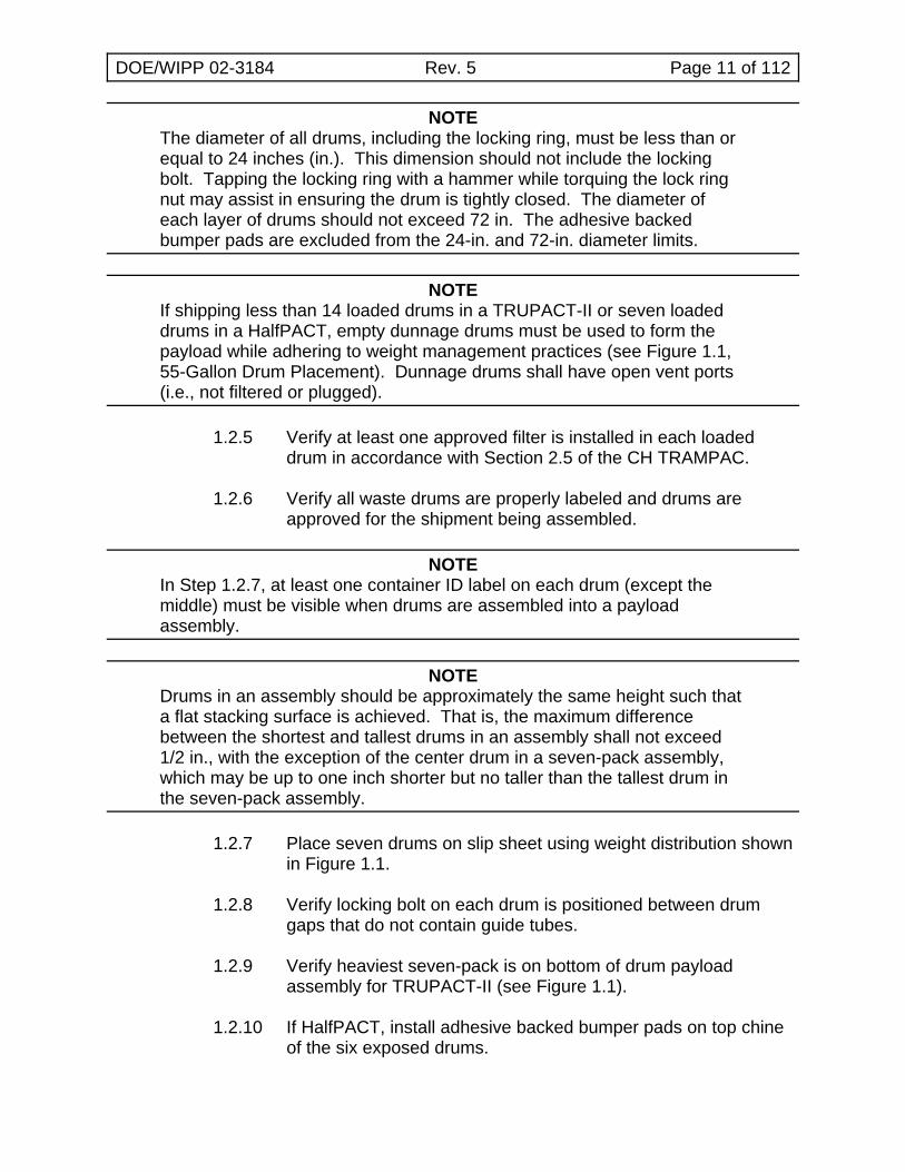
NOTEThe diameter of all drums, including the locking ring, must be less than orequal to 24 inches (in.). This dimension should not include the lockingbolt. Tapping the locking ring with a hammer while torquing the lock ringnut may assist in ensuring the drum is tightly closed. The diameter ofeach layer of drums should not exceed 72 in. The adhesive backedbumper pads are excluded from the 24-in. and 72-in. diameter limits.
NOTEIf shipping less than 14 loaded drums in a TRUPACT-II or seven loadeddrums in a HalfPACT, empty dunnage drums must be used to form thepayload while adhering to weight management practices (see Figure 1.1,55-Gallon Drum Placement). Dunnage drums shall have open vent ports(i.e., not filtered or plugged).
1.2.5 Verify at least one approved filter is installed in each loadeddrum in accordance with Section 2.5 of the CH TRAMPAC.
1.2.6 Verify all waste drums are properly labeled and drums areapproved for the shipment being assembled.
NOTEIn Step 1.2.7, at least one container ID label on each drum (except themiddle) must be visible when drums are assembled into a payloadassembly.
NOTEDrums in an assembly should be approximately the same height such thata flat stacking surface is achieved. That is, the maximum differencebetween the shortest and tallest drums in an assembly shall not exceed1/2 in., with the exception of the center drum in a seven-pack assembly,which may be up to one inch shorter but no taller than the tallest drum inthe seven-pack assembly.
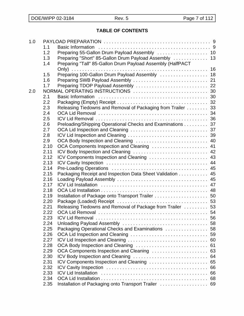
1.2.7 Place seven drums on slip sheet using weight distribution shownin Figure 1.1.
1.2.8 Verify locking bolt on each drum is positioned between drumgaps that do not contain guide tubes.
1.2.9 Verify heaviest seven-pack is on bottom of drum payloadassembly for TRUPACT-II (see Figure 1.1).
1.2.10 If HalfPACT, install adhesive backed bumper pads on top chineof the six exposed drums.
DOE/WIPP 02-3184 Rev. 5 Page 12 of 112
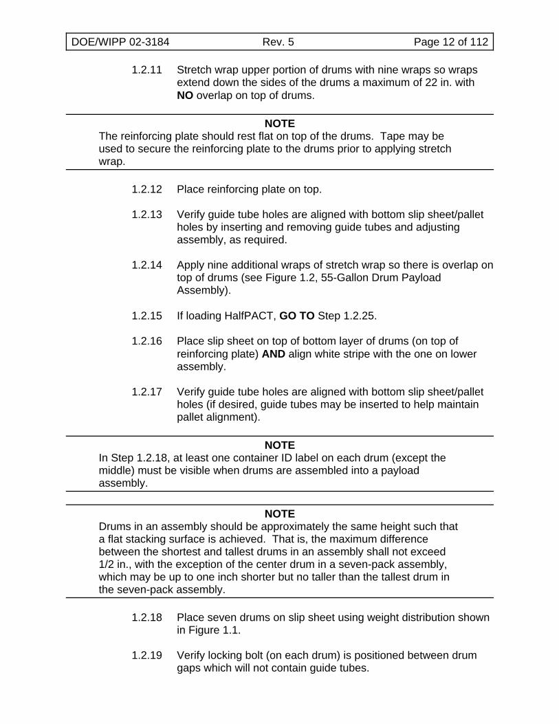
1.2.11 Stretch wrap upper portion of drums with nine wraps so wrapsextend down the sides of the drums a maximum of 22 in. withNO overlap on top of drums.
NOTEThe reinforcing plate should rest flat on top of the drums. Tape may beused to secure the reinforcing plate to the drums prior to applying stretchwrap.
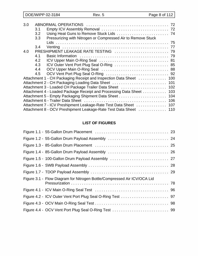
1.2.12 Place reinforcing plate on top.
1.2.13 Verify guide tube holes are aligned with bottom slip sheet/palletholes by inserting and removing guide tubes and adjustingassembly, as required.
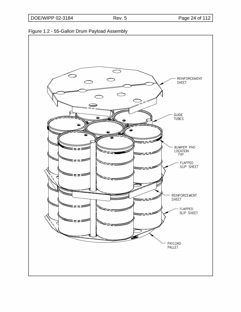
1.2.14 Apply nine additional wraps of stretch wrap so there is overlap ontop of drums (see Figure 1.2, 55-Gallon Drum PayloadAssembly).
1.2.15 If loading HalfPACT, GO TO Step 1.2.25.
1.2.16 Place slip sheet on top of bottom layer of drums (on top ofreinforcing plate) AND align white stripe with the one on lowerassembly.
1.2.17 Verify guide tube holes are aligned with bottom slip sheet/palletholes (if desired, guide tubes may be inserted to help maintainpallet alignment).
NOTEIn Step 1.2.18, at least one container ID label on each drum (except themiddle) must be visible when drums are assembled into a payloadassembly.
NOTEDrums in an assembly should be approximately the same height such thata flat stacking surface is achieved. That is, the maximum differencebetween the shortest and tallest drums in an assembly shall not exceed1/2 in., with the exception of the center drum in a seven-pack assembly,which may be up to one inch shorter but no taller than the tallest drum inthe seven-pack assembly.
1.2.18 Place seven drums on slip sheet using weight distribution shownin Figure 1.1.
1.2.19 Verify locking bolt (on each drum) is positioned between drumgaps which will not contain guide tubes.
DOE/WIPP 02-3184 Rev. 5 Page 13 of 112
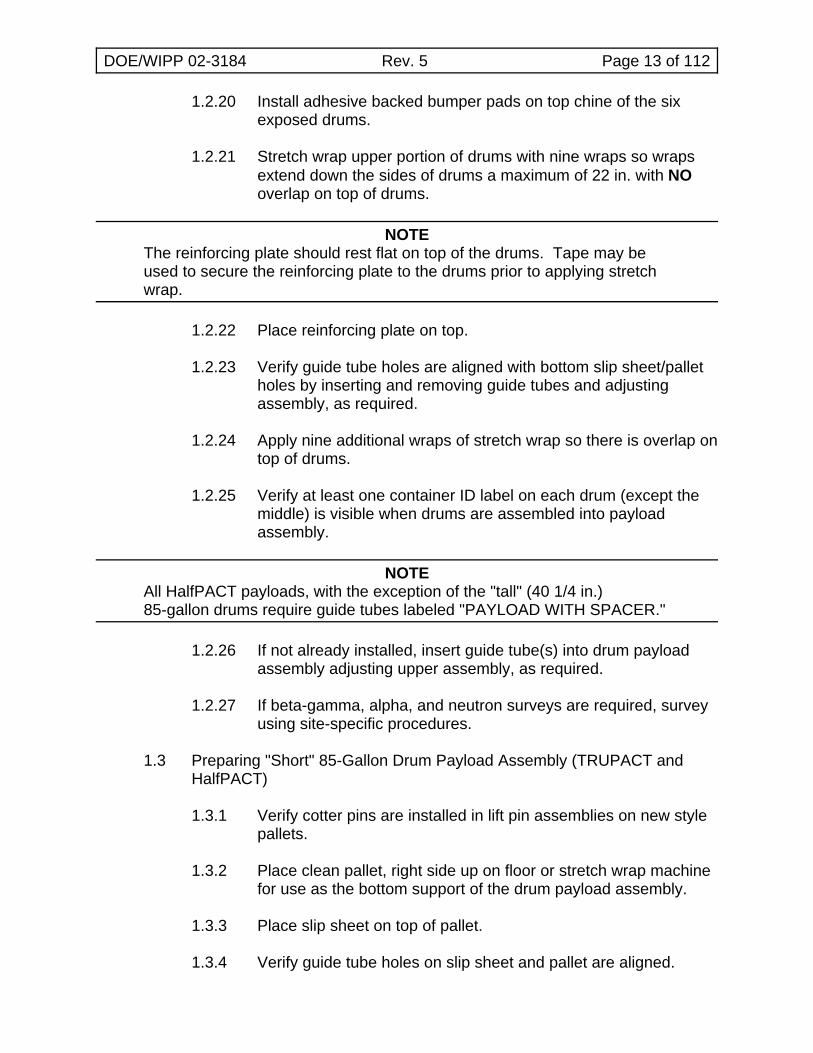
1.2.20 Install adhesive backed bumper pads on top chine of the sixexposed drums.
1.2.21 Stretch wrap upper portion of drums with nine wraps so wrapsextend down the sides of drums a maximum of 22 in. with NOoverlap on top of drums.
NOTEThe reinforcing plate should rest flat on top of the drums. Tape may beused to secure the reinforcing plate to the drums prior to applying stretchwrap.
1.2.22 Place reinforcing plate on top.
1.2.23 Verify guide tube holes are aligned with bottom slip sheet/palletholes by inserting and removing guide tubes and adjustingassembly, as required.
1.2.24 Apply nine additional wraps of stretch wrap so there is overlap ontop of drums.
1.2.25 Verify at least one container ID label on each drum (except themiddle) is visible when drums are assembled into payloadassembly.
NOTEAll HalfPACT payloads, with the exception of the "tall" (40 1/4 in.)85-gallon drums require guide tubes labeled "PAYLOAD WITH SPACER."
1.2.26 If not already installed, insert guide tube(s) into drum payloadassembly adjusting upper assembly, as required.
1.2.27 If beta-gamma, alpha, and neutron surveys are required, surveyusing site-specific procedures.
1.3 Preparing "Short" 85-Gallon Drum Payload Assembly (TRUPACT andHalfPACT)
1.3.1 Verify cotter pins are installed in lift pin assemblies on new stylepallets.
1.3.2 Place clean pallet, right side up on floor or stretch wrap machinefor use as the bottom support of the drum payload assembly.
1.3.3 Place slip sheet on top of pallet.
1.3.4 Verify guide tube holes on slip sheet and pallet are aligned.
DOE/WIPP 02-3184 Rev. 5 Page 14 of 112
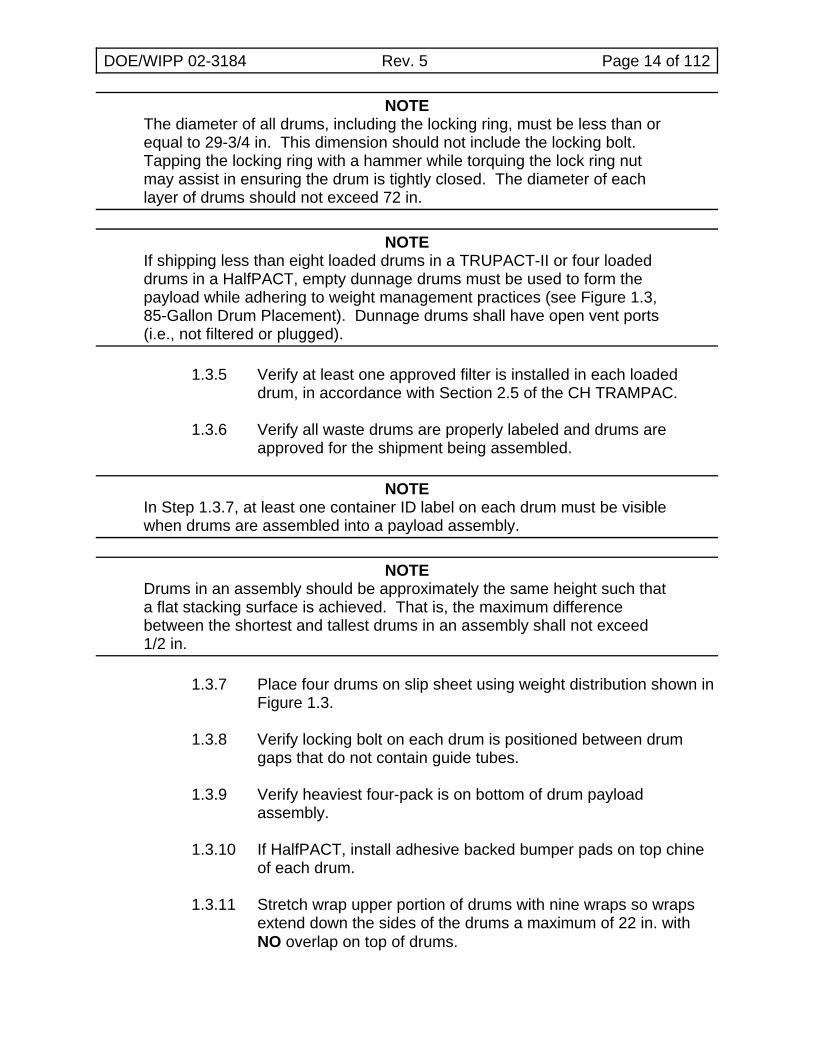
NOTEThe diameter of all drums, including the locking ring, must be less than orequal to 29-3/4 in. This dimension should not include the locking bolt. Tapping the locking ring with a hammer while torquing the lock ring nutmay assist in ensuring the drum is tightly closed. The diameter of eachlayer of drums should not exceed 72 in.
NOTEIf shipping less than eight loaded drums in a TRUPACT-II or four loadeddrums in a HalfPACT, empty dunnage drums must be used to form thepayload while adhering to weight management practices (see Figure 1.3,85-Gallon Drum Placement). Dunnage drums shall have open vent ports(i.e., not filtered or plugged).
1.3.5 Verify at least one approved filter is installed in each loadeddrum, in accordance with Section 2.5 of the CH TRAMPAC.
1.3.6 Verify all waste drums are properly labeled and drums areapproved for the shipment being assembled.
NOTEIn Step 1.3.7, at least one container ID label on each drum must be visiblewhen drums are assembled into a payload assembly.
NOTEDrums in an assembly should be approximately the same height such thata flat stacking surface is achieved. That is, the maximum differencebetween the shortest and tallest drums in an assembly shall not exceed1/2 in.
1.3.7 Place four drums on slip sheet using weight distribution shown inFigure 1.3.
1.3.8 Verify locking bolt on each drum is positioned between drumgaps that do not contain guide tubes.
1.3.9 Verify heaviest four-pack is on bottom of drum payloadassembly.
1.3.10 If HalfPACT, install adhesive backed bumper pads on top chineof each drum.
1.3.11 Stretch wrap upper portion of drums with nine wraps so wrapsextend down the sides of the drums a maximum of 22 in. withNO overlap on top of drums.
DOE/WIPP 02-3184 Rev. 5 Page 15 of 112
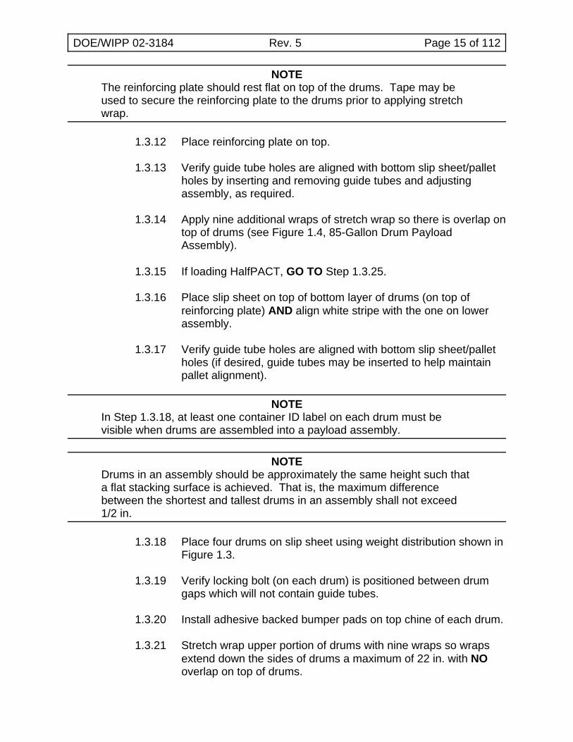
NOTEThe reinforcing plate should rest flat on top of the drums. Tape may beused to secure the reinforcing plate to the drums prior to applying stretchwrap.
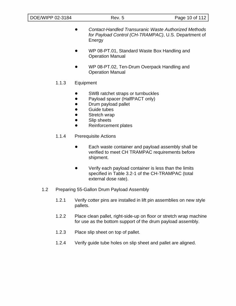
1.3.12 Place reinforcing plate on top.
1.3.13 Verify guide tube holes are aligned with bottom slip sheet/palletholes by inserting and removing guide tubes and adjustingassembly, as required.
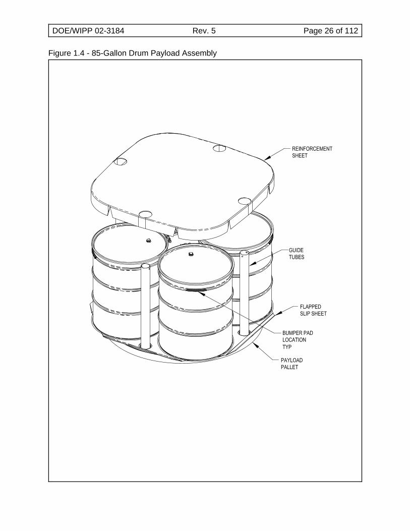
1.3.14 Apply nine additional wraps of stretch wrap so there is overlap ontop of drums (see Figure 1.4, 85-Gallon Drum PayloadAssembly).
1.3.15 If loading HalfPACT, GO TO Step 1.3.25.
1.3.16 Place slip sheet on top of bottom layer of drums (on top ofreinforcing plate) AND align white stripe with the one on lowerassembly.
1.3.17 Verify guide tube holes are aligned with bottom slip sheet/palletholes (if desired, guide tubes may be inserted to help maintainpallet alignment).
NOTEIn Step 1.3.18, at least one container ID label on each drum must bevisible when drums are assembled into a payload assembly.
NOTEDrums in an assembly should be approximately the same height such thata flat stacking surface is achieved. That is, the maximum differencebetween the shortest and tallest drums in an assembly shall not exceed1/2 in.
1.3.18 Place four drums on slip sheet using weight distribution shown inFigure 1.3.
1.3.19 Verify locking bolt (on each drum) is positioned between drumgaps which will not contain guide tubes.
1.3.20 Install adhesive backed bumper pads on top chine of each drum.
1.3.21 Stretch wrap upper portion of drums with nine wraps so wrapsextend down the sides of drums a maximum of 22 in. with NOoverlap on top of drums.
DOE/WIPP 02-3184 Rev. 5 Page 16 of 112
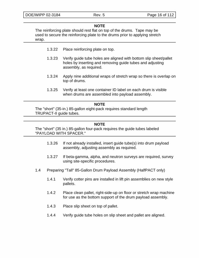
NOTEThe reinforcing plate should rest flat on top of the drums. Tape may beused to secure the reinforcing plate to the drums prior to applying stretchwrap.
1.3.22 Place reinforcing plate on top.
1.3.23 Verify guide tube holes are aligned with bottom slip sheet/palletholes by inserting and removing guide tubes and adjustingassembly, as required.
1.3.24 Apply nine additional wraps of stretch wrap so there is overlap ontop of drums.
1.3.25 Verify at least one container ID label on each drum is visiblewhen drums are assembled into payload assembly.
NOTEThe "short" (35-in.) 85-gallon eight-pack requires standard lengthTRUPACT-II guide tubes.
NOTEThe "short" (35 in.) 85-gallon four-pack requires the guide tubes labeled"PAYLOAD WITH SPACER."
1.3.26 If not already installed, insert guide tube(s) into drum payloadassembly, adjusting assembly as required.
1.3.27 If beta-gamma, alpha, and neutron surveys are required, surveyusing site-specific procedures.
1.4 Preparing "Tall" 85-Gallon Drum Payload Assembly (HalfPACT only)
1.4.1 Verify cotter pins are installed in lift pin assemblies on new stylepallets.
1.4.2 Place clean pallet, right-side-up on floor or stretch wrap machinefor use as the bottom support of the drum payload assembly.
1.4.3 Place slip sheet on top of pallet.
1.4.4 Verify guide tube holes on slip sheet and pallet are aligned.
DOE/WIPP 02-3184 Rev. 5 Page 17 of 112
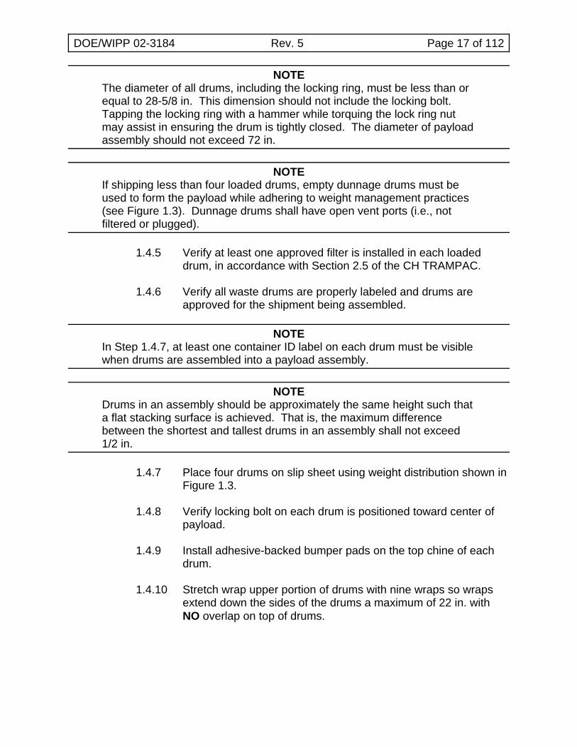
NOTEThe diameter of all drums, including the locking ring, must be less than orequal to 28-5/8 in. This dimension should not include the locking bolt. Tapping the locking ring with a hammer while torquing the lock ring nutmay assist in ensuring the drum is tightly closed. The diameter of payloadassembly should not exceed 72 in.
NOTEIf shipping less than four loaded drums, empty dunnage drums must beused to form the payload while adhering to weight management practices(see Figure 1.3). Dunnage drums shall have open vent ports (i.e., notfiltered or plugged).
1.4.5 Verify at least one approved filter is installed in each loadeddrum, in accordance with Section 2.5 of the CH TRAMPAC.
1.4.6 Verify all waste drums are properly labeled and drums areapproved for the shipment being assembled.
NOTEIn Step 1.4.7, at least one container ID label on each drum must be visiblewhen drums are assembled into a payload assembly.
NOTEDrums in an assembly should be approximately the same height such thata flat stacking surface is achieved. That is, the maximum differencebetween the shortest and tallest drums in an assembly shall not exceed1/2 in.
1.4.7 Place four drums on slip sheet using weight distribution shown inFigure 1.3.
1.4.8 Verify locking bolt on each drum is positioned toward center ofpayload.
1.4.9 Install adhesive-backed bumper pads on the top chine of eachdrum.
1.4.10 Stretch wrap upper portion of drums with nine wraps so wrapsextend down the sides of the drums a maximum of 22 in. withNO overlap on top of drums.
DOE/WIPP 02-3184 Rev. 5 Page 18 of 112
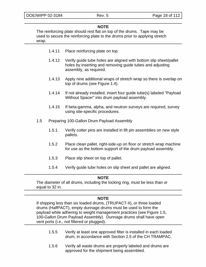
NOTEThe reinforcing plate should rest flat on top of the drums. Tape may beused to secure the reinforcing plate to the drums prior to applying stretchwrap.
1.4.11 Place reinforcing plate on top.
1.4.12 Verify guide tube holes are aligned with bottom slip sheet/palletholes by inserting and removing guide tubes and adjustingassembly, as required.
1.4.13 Apply nine additional wraps of stretch wrap so there is overlap ontop of drums (see Figure 1.4).
1.4.14 If not already installed, insert four guide tube(s) labeled "PayloadWithout Spacer" into drum payload assembly.
1.4.15 If beta-gamma, alpha, and neutron surveys are required, surveyusing site-specific procedures.
1.5 Preparing 100-Gallon Drum Payload Assembly
1.5.1 Verify cotter pins are installed in lift pin assemblies on new stylepallets.
1.5.2 Place clean pallet, right-side-up on floor or stretch wrap machinefor use as the bottom support of the drum payload assembly.
1.5.3 Place slip sheet on top of pallet.
1.5.4 Verify guide tube holes on slip sheet and pallet are aligned.
NOTEThe diameter of all drums, including the locking ring, must be less than orequal to 32 in.
NOTEIf shipping less than six loaded drums, (TRUPACT-II), or three loadeddrums (HalfPACT), empty dunnage drums must be used to form thepayload while adhering to weight management practices (see Figure 1.5,100-Gallon Drum Payload Assembly). Dunnage drums shall have openvent ports (i.e., not filtered or plugged).
1.5.5 Verify at least one approved filter is installed in each loadeddrum, in accordance with Section 2.5 of the CH TRAMPAC.
1.5.6 Verify all waste drums are properly labeled and drums areapproved for the shipment being assembled.
DOE/WIPP 02-3184 Rev. 5 Page 19 of 112
NOTEIn Step 1.5.7, at least one container ID label on each drum must be visiblewhen drums are assembled into a payload assembly.
NOTEDrums in an assembly should be approximately the same height such thata flat stacking surface is achieved. That is, the maximum differencebetween the shortest and tallest drums in an assembly shall not exceed1/2 in.
1.5.7 Place three drums on slip sheet.
1.5.8 If the drums are equipped with lock rings/bolts, verify locking bolton each drum is NOT located in the center or near the outerperimeter.
1.5.9 Verify heaviest three-pack is on bottom of drum payloadassembly for TRUPACT-II (see Figure 1.5).
1.5.10 If payload assembly is for HalfPACT, install adhesive-backedbumper pads on the top chine of each drum.
1.5.11 Stretch wrap upper portion of drums with nine wraps so wrapsextend down the sides of the drums a maximum of 22 in. withNO overlap on top of drums.
NOTEThe reinforcing plate should rest flat on top of the drums. Tape may beused to secure the reinforcing plate to the drums prior to applying stretchwrap.
1.5.12 Place reinforcing plate on top.
1.5.13 Verify guide tube holes are aligned with bottom slip sheet/palletholes by inserting and removing guide tubes and adjustingassembly, as required.
1.5.14 Apply nine additional wraps of stretch wrap so there is overlap ontop of drums (see Figure 1.5).
1.5.15 If payload assembly is for HalfPACT, GO TO Step 1.5.25.
1.5.16 Place slip sheet on top of bottom layer of drums (on top ofreinforcing plate).
1.5.17 Verify guide tube holes are aligned with bottom slip sheet/palletholes (if desired, guide tubes may be inserted to help maintainpallet alignment).
DOE/WIPP 02-3184 Rev. 5 Page 20 of 112
NOTEIn Step 1.5.18, at least one container ID label on each drum must bevisible when drums are assembled into a payload assembly.
NOTEDrums in an assembly should be approximately the same height such thata flat stacking surface is achieved. That is, the maximum differencebetween the shortest and tallest drums in an assembly shall not exceed1/2 in.
1.5.18 Place three drums on slip sheet.
1.5.19 Verify locking bolt (on each drum) is NOT located in the center ornear the outer perimeter.
1.5.20 Install adhesive backed bumper pads on top chine of each drum.
1.5.21 Stretch wrap upper portion of drums with nine wraps so wrapsextend down the sides of drums a maximum of 22 in. with NOoverlap on top of drums.
NOTEThe reinforcing plate should rest flat on top of the drums. Tape may beused to secure the reinforcing plate to the drums prior to applying stretchwrap.
1.5.22 Place reinforcing plate on top.
1.5.23 Verify guide tube holes are aligned with bottom slip sheet/palletholes by inserting and removing guide tubes and adjustingassembly, as required.
1.5.24 Apply nine additional wraps of stretch wrap so there is overlap ontop of drums.
1.5.25 Verify at least one container ID label on each drum is visiblewhen drums are assembled into payload assembly.
DOE/WIPP 02-3184 Rev. 5 Page 21 of 112
NOTEThe 100-gallon drum three-pack requires the guide tubes labeled"PAYLOAD with SPACER."
NOTEThe 100-gallon drum six-pack requires the standard length TRUPACT-IIguide tubes.
1.5.26 If not already installed, insert guide tube(s) into drum payloadassembly adjusting assembly, as required.
1.5.27 If beta-gamma, alpha, and neutron surveys are required, surveyusing site-specific procedures.
1.6 Preparing SWB Payload Assembly
NOTEAdditional guidance regarding SWB activities, such as loading, handling,filter installation, maintenance, inspection, and repair, is provided inWP 08-PT.01. This document is available on the Internet athttp://www.wipp.energy.gov/library/caolib.htm#containers.
NOTEHalfPACT payloads include one SWB and a HalfPACT payload spacer.
NOTEThe maximum SWB payload assembly height is 74-5/8 in.
1.6.1 Verify approved filters are installed in each SWB and theremaining ports are plugged (if not filtered), in accordance withSection 2.5 of the CH TRAMPAC.
NOTEIf shipping only one loaded SWB in a TRUPACT-II, a second emptydunnage SWB must be used in the top position to form the payload. Toallow for pressure changes, dunnage SWBs shall have open vent ports(i.e., not filtered or plugged).
1.6.2 Verify SWBs are properly labeled and SWBs are approved forthe shipment being assembled.
NOTEAn SWB forklift adapter may be used in lieu of a crane/ACGLF.
1.6.3 Place heaviest SWB on floor.
DOE/WIPP 02-3184 Rev. 5 Page 22 of 112
CAUTION
Operator shall verify two ACGLF counterweights are at 180 degrees and000 degrees (+ 2 degrees) BEFORE lifting ACGLF or lid.
1.6.4 Place second SWB on top of first and align the edges.
1.6.5 Attach SWB turnbuckles or adjustable slings (in three places) totop and bottom SWBs as follows:
! One on each outer lift clip on one side
! One on the middle clip on the opposite side (seeFigure 1.6, SWB Payload Assembly)
1.6.6 Install SWB bumper pads (On the top SWB, the bumpers shouldbe placed at the end of the top ribs only. On the bottom SWB,the bumpers should be placed at the end of the bottom ribs only).
1.6.7 If beta-gamma, alpha, and neutron surveys are required, surveyusing site-specific procedures.
1.7 Preparing TDOP Payload Assembly (TRUPACT-II only)
NOTEAdditional guidance regarding TDOP operations, such as handling, filterinstallation, loading, lifting, inspection, maintenance, and repair, isprovided in WP 08-PT.02. This document is available on the Internet athttp://www.wipp.energy.gov/library/caolib.htm#containers.
1.7.1 Verify approved filters are installed and the remaining ports areplugged (if not filtered), in accordance with Section 2.5 of theCH TRAMPAC.
1.7.2 Verify the TDOP is properly labeled and TDOP is approved forthe shipment being assembled.
1.7.3 Install bumper pads on the top and bottom rib of TDOP(four pads on each rib). (See Figure 1.7, TDOP PayloadAssembly.)
1.7.4 If beta-gamma, alpha, and neutron surveys are required, surveyusing site-specific procedures.
DOE/WIPP 02-3184 Rev. 5 Page 23 of 112
(2) (7)
(4)
(3)(6)
(5) (1)
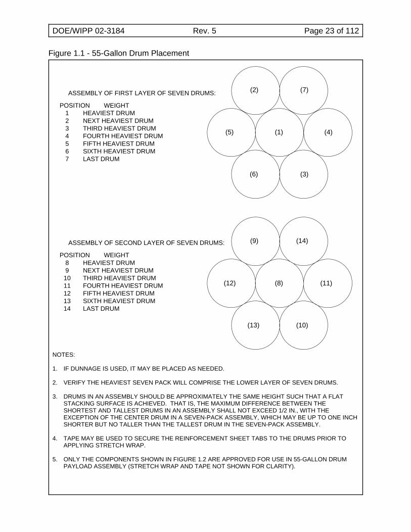
ASSEMBLY OF FIRST LAYER OF SEVEN DRUMS:
(8)(12)
(13)
(9)
(10)
(11)
(14)
POSITION WEIGHT 1 HEAVIEST DRUM 2 NEXT HEAVIEST DRUM 3 THIRD HEAVIEST DRUM 4 FOURTH HEAVIEST DRUM 5 FIFTH HEAVIEST DRUM 6 SIXTH HEAVIEST DRUM 7 LAST DRUM
POSITION WEIGHT 8 HEAVIEST DRUM 9 NEXT HEAVIEST DRUM 10 THIRD HEAVIEST DRUM 11 FOURTH HEAVIEST DRUM 12 FIFTH HEAVIEST DRUM 13 SIXTH HEAVIEST DRUM 14 LAST DRUM
ASSEMBLY OF SECOND LAYER OF SEVEN DRUMS:
Figure 1.1 - 55-Gallon Drum Placement
NOTES:
1. IF DUNNAGE IS USED, IT MAY BE PLACED AS NEEDED.
2. VERIFY THE HEAVIEST SEVEN PACK WILL COMPRISE THE LOWER LAYER OF SEVEN DRUMS.
3. DRUMS IN AN ASSEMBLY SHOULD BE APPROXIMATELY THE SAME HEIGHT SUCH THAT A FLATSTACKING SURFACE IS ACHIEVED. THAT IS, THE MAXIMUM DIFFERENCE BETWEEN THESHORTEST AND TALLEST DRUMS IN AN ASSEMBLY SHALL NOT EXCEED 1/2 IN., WITH THEEXCEPTION OF THE CENTER DRUM IN A SEVEN-PACK ASSEMBLY, WHICH MAY BE UP TO ONE INCHSHORTER BUT NO TALLER THAN THE TALLEST DRUM IN THE SEVEN-PACK ASSEMBLY.
4. TAPE MAY BE USED TO SECURE THE REINFORCEMENT SHEET TABS TO THE DRUMS PRIOR TOAPPLYING STRETCH WRAP.
5. ONLY THE COMPONENTS SHOWN IN FIGURE 1.2 ARE APPROVED FOR USE IN 55-GALLON DRUMPAYLOAD ASSEMBLY (STRETCH WRAP AND TAPE NOT SHOWN FOR CLARITY).
DOE/WIPP 02-3184 Rev. 5 Page 24 of 112
Figure 1.2 - 55-Gallon Drum Payload Assembly
DOE/WIPP 02-3184 Rev. 5 Page 25 of 112
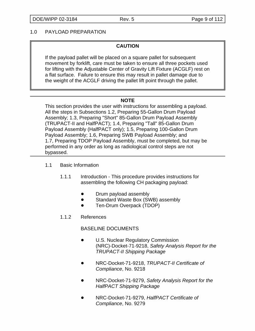
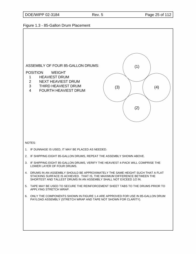
ASSEMBLY OF FOUR 85-GALLON DRUMS:
POSITION WEIGHT 1 HEAVIEST DRUM 2 NEXT HEAVIEST DRUM 3 THIRD HEAVIEST DRUM 4 FOURTH HEAVIEST DRUM
(1)
(2)
(4)(3)
Figure 1.3 - 85-Gallon Drum Placement
NOTES:
1. IF DUNNAGE IS USED, IT MAY BE PLACED AS NEEDED.
2. IF SHIPPING EIGHT 85-GALLON DRUMS, REPEAT THE ASSEMBLY SHOWN ABOVE.
3. IF SHIPPING EIGHT 85-GALLON DRUMS, VERIFY THE HEAVIEST 4-PACK WILL COMPRISE THELOWER LAYER OF FOUR DRUMS.
4. DRUMS IN AN ASSEMBLY SHOULD BE APPROXIMATELY THE SAME HEIGHT SUCH THAT A FLATSTACKING SURFACE IS ACHIEVED. THAT IS, THE MAXIMUM DIFFERENCE BETWEEN THESHORTEST AND TALLEST DRUMS IN AN ASSEMBLY SHALL NOT EXCEED 1/2 IN.
5. TAPE MAY BE USED TO SECURE THE REINFORCEMENT SHEET TABS TO THE DRUMS PRIOR TOAPPLYING STRETCH WRAP.
6. ONLY THE COMPONENTS SHOWN IN FIGURE 1.4 ARE APPROVED FOR USE IN 85-GALLON DRUMPAYLOAD ASSEMBLY (STRETCH WRAP AND TAPE NOT SHOWN FOR CLARITY).
DOE/WIPP 02-3184 Rev. 5 Page 26 of 112
Figure 1.4 - 85-Gallon Drum Payload Assembly
DOE/WIPP 02-3184 Rev. 5 Page 27 of 112
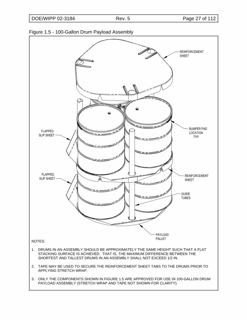
Figure 1.5 - 100-Gallon Drum Payload Assembly
NOTES:
1. DRUMS IN AN ASSEMBLY SHOULD BE APPROXIMATELY THE SAME HEIGHT SUCH THAT A FLATSTACKING SURFACE IS ACHIEVED. THAT IS, THE MAXIMUM DIFFERENCE BETWEEN THESHORTEST AND TALLEST DRUMS IN AN ASSEMBLY SHALL NOT EXCEED 1/2 IN.
2. TAPE MAY BE USED TO SECURE THE REINFORCEMENT SHEET TABS TO THE DRUMS PRIOR TOAPPLYING STRETCH WRAP.
3. ONLY THE COMPONENTS SHOWN IN FIGURE 1.5 ARE APPROVED FOR USE IN 100-GALLON DRUMPAYLOAD ASSEMBLY (STRETCH WRAP AND TAPE NOT SHOWN FOR CLARITY).
DOE/WIPP 02-3184 Rev. 5 Page 28 of 112
BUMPER PADLOCATION
TYP
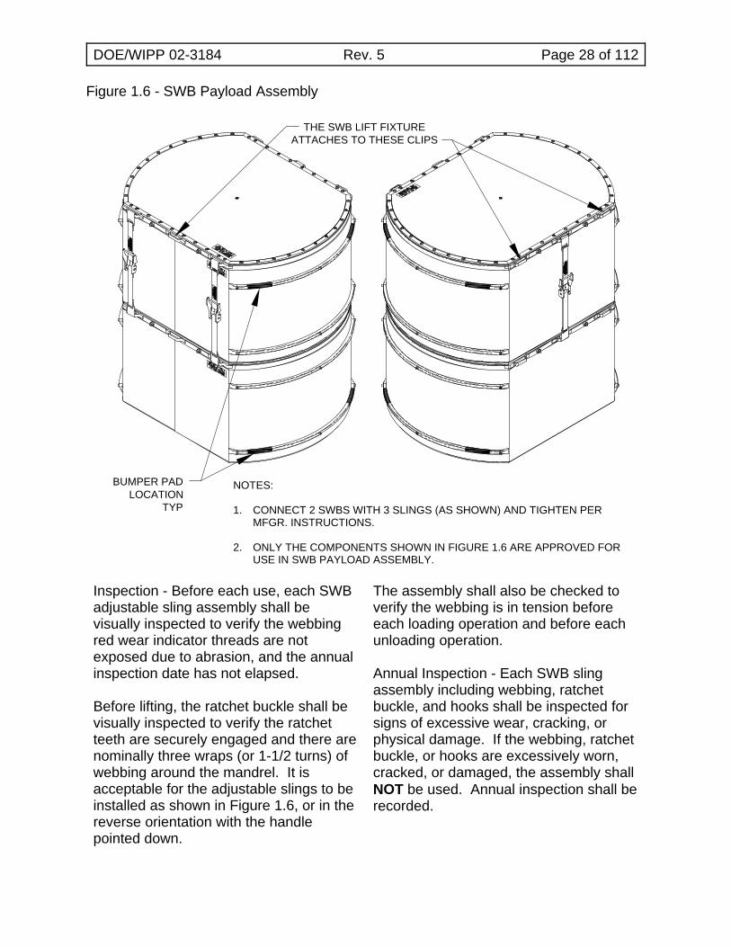
THE SWB LIFT FIXTUREATTACHES TO THESE CLIPS
Figure 1.6 - SWB Payload Assembly
NOTES:
1. CONNECT 2 SWBS WITH 3 SLINGS (AS SHOWN) AND TIGHTEN PERMFGR. INSTRUCTIONS.
2. ONLY THE COMPONENTS SHOWN IN FIGURE 1.6 ARE APPROVED FORUSE IN SWB PAYLOAD ASSEMBLY.
Inspection - Before each use, each SWBadjustable sling assembly shall bevisually inspected to verify the webbingred wear indicator threads are notexposed due to abrasion, and the annualinspection date has not elapsed.
Before lifting, the ratchet buckle shall bevisually inspected to verify the ratchetteeth are securely engaged and there arenominally three wraps (or 1-1/2 turns) ofwebbing around the mandrel. It isacceptable for the adjustable slings to beinstalled as shown in Figure 1.6, or in thereverse orientation with the handlepointed down.
The assembly shall also be checked toverify the webbing is in tension beforeeach loading operation and before eachunloading operation.
Annual Inspection - Each SWB slingassembly including webbing, ratchetbuckle, and hooks shall be inspected forsigns of excessive wear, cracking, orphysical damage. If the webbing, ratchetbuckle, or hooks are excessively worn,cracked, or damaged, the assembly shallNOT be used. Annual inspection shall berecorded.
DOE/WIPP 02-3184 Rev. 5 Page 29 of 112
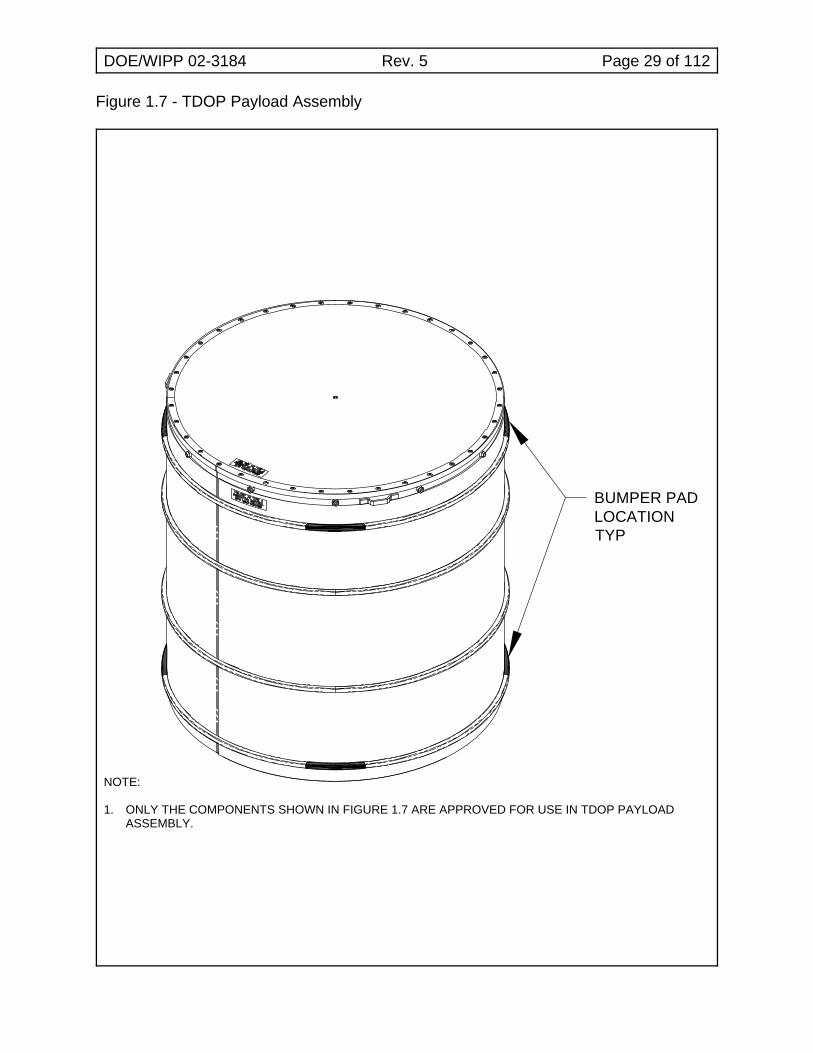
BUMPER PADLOCATIONTYP
Figure 1.7 - TDOP Payload Assembly
NOTE:
1. ONLY THE COMPONENTS SHOWN IN FIGURE 1.7 ARE APPROVED FOR USE IN TDOP PAYLOADASSEMBLY.
DOE/WIPP 02-3184 Rev. 5 Page 30 of 112
2.0 NORMAL OPERATING INSTRUCTIONS
CAUTION
If the payload pallet will be placed on a square pallet for subsequentmovement by forklift, care must be taken to ensure all three pockets usedfor lifting with the ACGLF rest on a flat surface. Failure to ensure this mayresult in pallet damage due to the weight of the ACGLF driving the palletlift point through the pallet.
NOTETorquing of components that are replaced using the minor maintenancework instructions (WIs) may be completed during assembly step and donot require a second or repeat torque when using minor maintenanceform.
NOTETransport trailer operations, package loading and unloading from transporttrailers, hoisting and rigging activities such as ACGLF operations,equipment checkout and shutdown, and component inspection activitiesmust be performed, but may be performed in any order and in parallel withother activities as long as radiological control steps are not bypassed. Steps involving OCA/ICV lid removal/installation and payloadremoval/loading may be performed in parallel if there are multipleoperators working on the same packaging.
2.1 Basic Information
2.1.1 Introduction - This procedure provides operating instructions forthe following CH packaging:
! TRUPACT-II! HalfPACT
2.1.2 References
! 49 CFR Part 172, "Hazardous Materials Table, SpecialProvisions, Hazardous Materials Communications,Emergency Response Information, and TrainingRequirements"
! 49 CFR Part 173, "Shippers - General Requirements forShipments and Packagings"
! U.S. Department of Energy, Safety Analysis Report for theTRUPACT-II Shipping Package
DOE/WIPP 02-3184 Rev. 5 Page 31 of 112
! TRUPACT-II Certificate of Compliance No. 9218
! U.S. Department of Energy, Safety Analysis Report for theHalfPACT Shipping Package
! HalfPACT Certificate of Compliance No. 9279
! Contact-Handled Transuranic Waste Authorized Methodsfor Payload Control (CH-TRAMPAC)
! DOE/WIPP 02-3183, CH Packaging Program Guidance
! DOE/WIPP 02-3185, CH Packaging Maintenance Manual
! WP 08-PT.04, CH Packaging Trailer O&M Manual
2.1.3 Equipment
! Calibrated Measuring and Test Equipment
- Pressure/vacuum gauge, 30-in. Hg to 30 psig
- Torque wrench with 10 to 65 pound inches (lb-in.)range
- Torque wrench with 30 to 50 pound feet (lb-ft) range
- Crane load cell, 10,000 lb minimum rating
! Other Equipment
- Inner Containment Vessel (ICV)/Outer ContainmentVessel (OCV) vent port plug removal/pressure relieftool
- Miscellaneous hardware and vacuum assemblyconnections
- Vacuum pump
- ICV/OCV outer vent port plug removal and installationtool
! Consumable Materials
- Vacuum grease- Nickel bearing lubricant- Denatured alcohol- Lint free rags
DOE/WIPP 02-3184 Rev. 5 Page 32 of 112
2.1.4 Precautions and Limitations
! Failure to rotate the counterweights on ACGLF to thebalance position may cause ACGLF to swinguncontrollably.
! Measures shall be implemented by all users for theidentification and control of parts and components. Thesemeasures shall be designed to prevent the use ofincorrect or defective parts and components on thepackaging.
! Jack stands are required on freestanding trailers onlywhen loading/unloading packaging on the trailer.
! Metal tools must not be used to remove O-rings.
! OCV/ICV lids shall be removed using a straight (vertical)pull; side pulls are not permitted.
! Marking devices used on packaging components shall below in chloride, fluoride, halide, and sulfur content.
2.2 Packaging (Empty) Receipt
NOTEThe packaging loading/unloading operation shall only be performed in adry environment. In the event of precipitation during outdoor operations,the OCV and ICV cavities shall be covered to prevent precipitation fromentering the package interior cavities. If precipitation does enter theinterior cavities, all freestanding water shall be removed before shipmentand liquid handled according to the sites waste management procedures.
2.2.1 Record OCA serial number on Attachment 1, CH PackagingReceipt and Inspection Data Sheet.
SIGN-OFF
DOE/WIPP 02-3184 Rev. 5 Page 33 of 112
2.2.2 Verify site representative performed the following:
! Released packaging for loading
! Validated shipping documents
! Inspected packaging for damage
! Checked nameplate to verify packages are proper forcontents being shipped
SIGN-OFF
2.2.3 Verify packaging maintenance labels are legible andmaintenance is current by checking maintenance labels adjacentto name plate and initial Attachment 1.
SIGN-OFF
2.2.4 Check for LEAK TEST REQUIRED tag near OCA vent port.
2.2.5 If LEAK TEST REQUIRED tag is present, remove tag andforward to supervisor so a leak test report will be sent to theWIPP M&O CH Packaging Maintenance Engineer.
CAUTION
A physical check shall be made to verify air bags on trailer have fullyinflated before trailer is moved. Failure to do so may cause the tires to rubon bottom of rear package.
2.2.6 Position transport trailer in designated parking area.
2.2.7 Lower trailer jacks (landing gear) ensuring trailer is level.
2.2.8 Install wheel chocks.
2.2.9 Install trailer stands on freestanding trailers.
2.3 Releasing Tiedowns and Removal of Packaging from Trailer
2.3.1 IF packaging will NOT be removed from trailer for loadingoperations,THEN GO TO Subsection 2.4, OCA Lid Removal.
2.3.2 Release tiedowns from packaging.
DOE/WIPP 02-3184 Rev. 5 Page 34 of 112
NOTETrailer tiedown guidance is provided in WP 08-PT.04. This document isavailable on the Internet athttp://www.wipp.energy.gov/library/caolib.htm#containers.
2.3.3 Rotate forklift pocket covers (4) to UP position,OR remove covers and store in designated area.
2.3.4 If required, dry packaging before transport to designated area.
CAUTION
Forklift tip-back beyond level may damage package exterior surface.
2.3.5 Transfer packaging to designated area.
2.4 OCA Lid Removal
2.4.1 Prepare OCA lid by removing the following:
! OCA lift pocket covers! OCA lock bolts (6)! OCV seal test port access plug and thermal plug! OCV vent port access plug and thermal plug
NOTEIf OCA lid is turned so that the OCV seal test port plug is not accessible,Step 2.4.2 cannot be performed; operator must proceed to Step 2.4.3.
2.4.2 Verify OCV seal test port plug is fully seated.
2.4.3 Remove OCV vent port cover.
2.4.4 Remove OCV vent port plug.
CAUTION
Operator shall verify two ACGLF counterweights are at 180 degreesand 000 degrees (+ 2 degrees) BEFORE lifting ACGLF or lid.
2.4.5 Attach ACGLF to OCA lid.
2.4.6 Install OCV vent port tool.
2.4.7 Connect vacuum line to vent port tool.
DOE/WIPP 02-3184 Rev. 5 Page 35 of 112
2.4.8 Start vacuum pump and evacuate to 3 to 15 in. Hg vacuumgauge.
2.4.9 Rotate OCV lock ring to UNLOCKED position.
2.4.10 Stop vacuum pump.
2.4.11 Disconnect vacuum line from vent port tool.
2.4.12 Remove vent port tool.
2.4.13 Let OCV vent to atmosphere.
CAUTION
Operator shall verify two ACGLF counterweights are at 180 degrees and000 degrees (+ 2 degrees) BEFORE lifting ACGLF or lid.
CAUTION
Load cell reading MUST NOT exceed 7,500 lb when weight of ACGLF iszeroed out, OR 10,000 lb when weight of ACGLF is included.
2.4.14 Remove OCA lid.
2.4.15 IF lid does not lift off, THEN perform the following:
[ A ] Contact supervisor.
[ B ] GO TO Subsection 3.2, Using Heat GunsOR Subsection 3.3, Pressurizing with Nitrogen orCompressed Air, attempt to remove lid andRETURN TO Step 2.4.16.
2.4.16 Place OCA lid on storage stand.
DOE/WIPP 02-3184 Rev. 5 Page 36 of 112
2.5 ICV Lid Removal
CAUTION
Operator shall verify two ACGLF counterweights are at 180 degreesand 000 degrees (+ 2 degrees) BEFORE lifting ACGLF or lid.
2.5.1 Attach ACGLF to ICV lid.
2.5.2 Remove ICV vent port cover.
2.5.3 Remove the following:
! ICV outer vent port plug ! ICV lock bolts (3)! ICV seal test port plug! OCV seal test port plug
2.5.4 Remove ICV inner vent port plug.
2.5.5 Install ICV vent port tool.
2.5.6 Connect vacuum line to vent port tool.
2.5.7 Start vacuum pump and evacuate to 3 to 15 in. Hg vacuumgauge.
2.5.8 Rotate ICV lock ring to UNLOCKED position.
2.5.9 Stop vacuum pump.
2.5.10 Disconnect vacuum line from vent port tool.
2.5.11 Remove vent port tool.
2.5.12 Vent ICV to atmosphere.
CAUTION
Load cell reading MUST NOT exceed 5,000 lb when weight of ACGLF iszeroed out, OR 7,500 lb when weight of ACGLF is included.
2.5.13 Remove ICV lid using ACGLF and crane.
DOE/WIPP 02-3184 Rev. 5 Page 37 of 112
2.5.14 IF lid does not lift off ICV, THEN perform the following:
[ A ] Contact supervisor.
[ B ] GO TO Subsection 3.2,OR Subsection 3.3, attempt to remove lid andRETURN TO Step 2.5.15.
2.5.15 Place ICV lid on storage stand.
NOTEUse of the ACGLF with short legs to remove items from the ICV is NOTpermitted.
2.5.16 Remove any payload pallets, guide tubes, slip sheets,reinforcement sheets, dunnage containers, etc.
2.6 Preloading/Shipping Operational Checks and Examinations
2.6.1 Radiological Control Technician (RCT), IF surveys for items inStep 2.7.1, Step 2.8.1, or Step 2.9.1 have been completedpreviously AND results are below contamination limits,THEN enter applicable data for each step on Attachment 1.
2.6.2 RCT, IF surveys have NOT been completed previously,THEN GO TO Subsection 2.7, OCA Lid Inspection and Cleaning,Subsection 2.8, ICV Lid Inspection and Cleaning, orSubsection 2.9, OCA Body Inspection and Cleaning, asapplicable.
NOTESubsections 2.7 through 2.13, ICV Cavity Inspection (and included steps),MUST be completed, but may be performed in any order as long asradiological control steps are not bypassed.
2.7 OCA Lid Inspection and Cleaning
2.7.1 RCT, IF survey has not been completed previously,THEN survey interior and exterior of OCA lid and recordapplicable data on Attachment 1.
SIGN-OFF
DOE/WIPP 02-3184 Rev. 5 Page 38 of 112
2.7.2 Inspect OCA lid for the following:
! Visible deformation
! Dents or abnormal flat spots > 1/2 in.
! Abnormal scratches or gouges
! Obvious punctures, tears, or cracks in exposed welds
! Plastic burnout plugs (3) in place and intact
! Fiberglass lift pocket tubes in place
! Distortions or cracks on or around lifting attachments
! Lift pocket covers attached and serviceable
! OCV locking Z-flange screws in place and no visible|space between screw head and locking Z-flange; if screws|are missing, or a space appears between screw head and|locking Z-flange, then go to corresponding WI.|
! Guide plates and screws in place, and screws torqued to21 + 2 lb-in., or verify no looseness in plate and screwsrecessed.
! Seal surfaces for scratches/gouges perpendicular tomachining marks
2.7.3 Remove foreign material from the following:
! Lock ring! Sealing surfaces! Test port access threads
2.7.4 Verify arrow above seal test port aligns with UNLOCKED arrowon lock ring.
2.7.5 Initial Attachment 1 to document OCA lid components andhardware are satisfactory.
SIGN-OFF
DOE/WIPP 02-3184 Rev. 5 Page 39 of 112
2.8 ICV Lid Inspection and Cleaning
NOTEO-rings are considered clean when they are absent of free-standingvacuum grease, dirt, debris, and other foreign matter.
2.8.1 RCT, IF survey has NOT been completed previously,THEN survey interior and exterior of ICV lid and recordapplicable data on Attachment 1.
SIGN-OFF
2.8.2 Inspect ICV lid for the following:
! Visible deformation
! Punctures
! Abnormal scratches or gouges
! Distortions on or around lifting attachments
! Upper spacer and screws installed and no visible space|between screw head and spacer top plate; if screws are|missing, or a space appears between screw head and|spacer top plate, then go to corresponding WI.|
! Debris shield installed and undamaged
! Lock ring undamaged
! Damaged or missing screws from wiper O-ring holder
! Seal surfaces for scratches/gouges perpendicular tomachining marks
2.8.3 Remove foreign material from the following:
! Lock ring flange! Debris shield! Sealing surfaces
2.8.4 Remove ICV wiper O-ring.
2.8.5 Clean ICV wiper O-ring and inspect for wear or damage thatcould impair its function.
DOE/WIPP 02-3184 Rev. 5 Page 40 of 112
2.8.6 IF O-ring is damaged,THEN GO TO corresponding WI and RETURN TO Step 2.8.9.
2.8.7 Lubricate wiper O-ring with a light coat of vacuum grease.
2.8.8 Install wiper O-ring.
2.8.9 Initial Attachment 1 to document ICV lid components andhardware are satisfactory.
SIGN-OFF
2.9 OCA Body Inspection and Cleaning
2.9.1 RCT, IF survey has NOT been completed previously,THEN survey OCA body exterior and ICV body interior andrecord applicable data on Attachment 1.
SIGN-OFF
2.9.2 Remove upper and lower main O-rings and set aside for cleaningand inspection.
2.9.3 Inspect OCA body for the following:
! Visible deformation
! Obvious punctures or tears
! Obvious cracks in exposed welds
! Dents or abnormal flat spots > 1/2 in.
! Abnormal scratches or gouges
! Plastic burnout plugs (6) in place and undamaged
! Forklift pocket cover threaded inserts (8) intact andthreads undamaged
! Lock bolt threaded inserts (6) intact and threadsundamaged
! Tears or fraying > 1/4 in. in ceramic fiber gasket
! Full width and length of ceramic fiber gasket adhered tolower Z-flange
DOE/WIPP 02-3184 Rev. 5 Page 41 of 112
! Lock ring stop(s) undamaged
! Upper and lower O-ring grooves and seal surfaces forscratches/gouges perpendicular to machining marks
2.9.4 Remove foreign material from the following:
! Test port threads! Vent port threads! Lock ring flange! O-ring grooves! Sealing surfaces
2.9.5 Verify air flow through OCV helium test ports.
2.9.6 Initial Attachment 1 to document OCA body inspection issatisfactory.
SIGN-OFF
2.10 OCA Components Inspection and Cleaning
NOTEO-rings are considered clean when they are absent of free-standingvacuum grease, dirt, debris, and other foreign matter.
2.10.1 Clean and inspect the following for wear or damage that couldimpair their function:
! OCV vent port plug and handling O-ring! OCV vent port cover and O-rings! OCV seal test port plug and seal O-ring! Lock bolts (6)! OCV seal test port access plug! OCV vent port access plug
2.10.2 IF components are damaged,THEN GO TO corresponding WI and RETURN TO Step 2.10.4.
2.10.3 Apply a light coat of vacuum grease to the following:
! OCV vent port plug threads! OCV vent port cover threads and seal O-ring! OCV seal test port plug threads and seal O-ring
2.10.4 Verify annulus debris seal is installed and undamaged.
DOE/WIPP 02-3184 Rev. 5 Page 42 of 112
2.10.5 Lightly coat the following with nickel bearing lubricant:
! OCA lock bolt threads (6)! OCV seal test port access plug threads! OCV vent port access plug threads
2.10.6 Clean and inspect upper and lower main O-rings and vent portplug seal O-ring for damage that could impair containmentintegrity.
2.10.7 IF O-rings are damaged,THEN GO TO corresponding WI and RETURN TO Step 2.10.10.
NOTELubrication and installation of upper and lower main O-rings may beperformed after Step 2.16.19, but prior to Subsection 2.18, OCA LidInstallation.
2.10.8 Lubricate upper and lower main O-rings and vent port plug sealO-ring with a light coat of vacuum grease.
2.10.9 Install upper and lower main O-rings and vent port plug sealO-ring.
2.10.10 Initial Attachment 1 to document OCA component and hardwareinspections are satisfactory.
SIGN-OFF
2.11 ICV Body Inspection and Cleaning
2.11.1 Remove upper and lower main O-rings and set aside for cleaningand inspection.
2.11.2 Inspect for the following:
! Lock ring stop(s) undamaged! Lock bolt threaded inserts installed and threads
undamaged
2.11.3 Remove foreign material from the following:
! Test port threads! Vent port threads! Lock ring flange! O-ring grooves! Filter ports! Sealing surfaces
DOE/WIPP 02-3184 Rev. 5 Page 43 of 112
2.11.4 Inspect the following:
! Upper and lower O-ring grooves and sealing surfaces forscratches/gouges perpendicular to machining marks
! Vent port threads for damage
! Seal test port threads for damage
! Lock ring flange for galling and burrs
! Lower spacer installed with no punctures in top plate
! Lower spacer screws installed and no detectable gapbetween screw head and spacer top plate
2.11.5 Verify airflow through ICV helium test ports.
2.11.6 Initial Attachment 1 to document ICV body inspection issatisfactory.
SIGN-OFF
2.12 ICV Components Inspection and Cleaning
NOTEO-rings are considered clean when they are absent of free-standingvacuum grease, dirt, debris, and other foreign matter.
2.12.1 Clean and inspect the following for wear or damage that couldimpair their function:
! ICV vent port cover and seal (gasket or O-ring)! ICV outer vent port plug! ICV inner vent port plug and seal O-ring! ICV seal test port plug and seal O-ring! ICV lock bolts (3)
2.12.2 IF components are damaged,THEN GO TO corresponding WI and RETURN TO Step 2.12.4.
2.12.3 Apply a light coat of vacuum grease to the following:
! ICV vent port cover threads (and O-ring if installed)! ICV outer vent port plug threads! ICV inner vent port plug threads and seal O-ring! ICV seal test port plug threads and seal O-ring
2.12.4 Coat ICV lock bolt threads (3) lightly with nickel bearing lubricant.
DOE/WIPP 02-3184 Rev. 5 Page 44 of 112
2.12.5 Clean upper and lower main O-rings and ICV outer vent port plugseal O-ring, and inspect for damage that could impaircontainment integrity.
2.12.6 IF O-rings are damaged,THEN GO TO corresponding WI and RETURN TO Step 2.12.9.
NOTELubrication and installation of upper and lower main O-rings may beperformed after Step 2.16.18, but prior to Subsection 2.17, ICV LidInstallation.
2.12.7 Lubricate upper and lower main O-rings and ICV outer vent portplug seal O-ring with a light coat of vacuum grease.
2.12.8 Install upper and lower main O-rings and ICV outer vent port plugseal O-ring.
2.12.9 Initial Attachment 1 to document ICV components and hardwareinspections are satisfactory.
SIGN-OFF
2.13 ICV Cavity Inspection
2.13.1 Check ICV cavity for water by visually inspecting the absorbentmaterial inserted into hole in lower spacer assembly.
NOTEDisposal of absorbent material and water will be at direction of RCT.
2.13.2 IF water is inside ICV,THEN perform one of the following:
! Remove water through center hole of lower spacerassembly using wet/dry vacuum
! Attach absorbent material to rod and insert in hole incenter of lower spacer assembly
2.13.3 IF water is inside ICV,THEN GO TO Subsection 3.1, Empty ICV Assembly Removal,perform steps and RETURN TO Step 2.13.4.
2.13.4 Initial Attachment 1 to document ICV is free of water.
SIGN-OFF
DOE/WIPP 02-3184 Rev. 5 Page 45 of 112
2.14 Pre-Loading Operations
2.14.1 Verify all pre-loading cleaning and inspections are complete.
SIGN-OFF
2.15 Packaging Receipt and Inspection Data Sheet Validation
2.15.1 Supervisor, review/validate and sign Attachment 1.
SIGN-OFF
2.16 Loading Payload Assembly
NOTEFor shipments to WIPP, shipper shall verify each payload containernumber has been entered into WIPP Waste Information System (WWIS)and verify shipment has been approved by WIPP WWIS DataAdministrator, and the final submittal has occurred.
2.16.1 Record OCA serial number on Attachment 2, CH PackagingLoading Data Sheet.
SIGN-OFF
2.16.2 Record pallet or SWB ratchet strap serial numbers onAttachment 2.
SIGN-OFF
2.16.3 Verify payload is assembled using requirements delineated in theCH-TRAMPAC and initial Attachment 2.
SIGN-OFF
CAUTION
Operator shall verify two ACGLF counterweights are at 180 degrees and000 degrees (+ 2 degrees) BEFORE lifting ACGLF or lid.
2.16.4 Attach appropriate legs/adapter to ACGLF.
DOE/WIPP 02-3184 Rev. 5 Page 46 of 112
NOTEHalfPACT payloads require a HalfPACT payload spacer for all assembliesexcept the "tall" (40-1/4 in.) 85-gallon four-pack.
2.16.5 Install HalfPACT payload spacer, if needed, otherwise,GO TO Step 2.16.6.
2.16.6 Lower ACGLF long legs into drum payload assembly guidetubes,OR lower SWB or TDOP adaptor until no load is indicated oncrane load cell.
2.16.7 Lock ACGLF legs,OR attach SWB lift fixture to upper SWB or TDOP adaptor toTDOP as applicable.
2.16.8 Raise payload 2 to 6 in.
2.16.9 If necessary, balance payload using counter weight controls atACGLF console until a reading of ± 0.5 degrees is obtained.
NOTEPayload assembly weight shall be equal to or less than the limits specifiedin the CH-TRAMPAC.
2.16.10 Record payload assembly weight (drum [or SWBs, TDOP] +spacer + pallet + guide tubes + slip sheets + ratchet straps +bumper pads + stretch wrap, etc.) on Attachment 2.
SIGN-OFF
2.16.11 Obtain packaging weight from WIPP WWIS PackagingReference Data Table.
2.16.12 Record empty packaging weight on Attachment 2.
SIGN-OFF
2.16.13 Add two previously recorded weight values to calculate the totalpackage weight and record on data sheet.
SIGN-OFF
2.16.14 Verify total loaded package weight does not exceed the limitsbelow:
! TRUPACT-II 19,250 lb! HalfPACT 18,100 lb
DOE/WIPP 02-3184 Rev. 5 Page 47 of 112
2.16.15 Raise and position payload assembly over ICV cavity usingcrane and ACGLF.
2.16.16 Verify payload is centered over ICV BEFORE lowering load.
CAUTION
Care should be exercised to avoid hitting, scraping, or binding the payloadassembly against ICV body flange and internal surface.
2.16.17 Lower payload assembly into ICV.
2.16.18 Record weight positions of ACGLF on top of payload near legopposite the electrical junction boxes.
CAUTION
Operator shall verify two ACGLF counterweights are at 180 degrees and000 degrees (± 2 degrees) BEFORE lifting ACGLF or lid.
2.16.19 Remove ACGLF/adaptor from payload.
2.17 ICV Lid Installation
2.17.1 Match ICV lid and body serial numbers and record ICV serialnumber on Attachment 2.
SIGN-OFF
2.17.2 Record torque wrench serial numbers and calibration due dateon Attachment 2.
SIGN-OFF
CAUTION
Operator shall verify two ACGLF counterweights are at 180 degrees and000 degrees (+ 2 degrees) BEFORE lifting ACGLF or lid.
2.17.3 Attach ACGLF to ICV lid.
2.17.4 Align UNLOCKED arrows and install ICV lid onto ICV body usingcrane and ACGLF.
DOE/WIPP 02-3184 Rev. 5 Page 48 of 112
2.17.5 Install ICV vent port tool into ICV vent port.
2.17.6 Connect vacuum line to ICV vent port tool.
CAUTION
Vacuum should not exceed 15-in. Hg when evacuating ICV cavity.
2.17.7 Start vacuum pump and evacuate to 3 to 15 in. Hg vacuumgauge.
2.17.8 Rotate ICV lock ring to LOCKED position.
2.17.9 Stop vacuum pump.
2.17.10 Disconnect vacuum line from vent port tool.
2.17.11 Remove ICV vent port tool.
2.17.12 Install ICV inner vent port plug.
2.17.13 Torque inner vent port plug to 55 to 65 lb-in.
SIGN-OFF
2.17.14 Perform ICV preshipment leakage rate test per Section 4.0,Preshipment Leakage Rate Testing.
SIGN-OFF
2.17.15 Install ICV lock bolts (3).
2.17.16 Torque each ICV lock bolt to 28 to 32 lb-ft.
SIGN-OFF
2.18 OCA Lid Installation
2.18.1 Verify that all items (tools, parts, rags, etc.) have been removedfrom the lower Z-flange/seal flange area(s).
SIGN-OFF
2.18.2 Match OCA lid and body serial numbers.
DOE/WIPP 02-3184 Rev. 5 Page 49 of 112
2.18.3 Record OCA serial number on Attachment 2.
SIGN-OFF
CAUTION
Operator shall verify two ACGLF counterweights are at 180 degrees and000 degrees (+ 2 degrees) BEFORE lifting ACGLF or lid.
2.18.4 Attach ACGLF to OCA lid.
2.18.5 Align UNLOCKED arrows and install OCA lid onto OCA body.
2.18.6 Verify OCV vent port plug is retracted into OCV vent port tool.
2.18.7 Install OCV vent port tool into OCV vent port.
2.18.8 Connect vacuum line to OCV vent port tool.
2.18.9 Start vacuum pump and evacuate to 3 to 15 in. Hg vacuumgauge.
2.18.10 Rotate OCV lock ring to LOCKED position.
2.18.11 Stop vacuum pump.
2.18.12 IF existing connection will be used for OCV leak test, THEN GO TO Step 2.18.14.
2.18.13 Disconnect vacuum line from vent port tool.
2.18.14 GO TO Section 4.0, perform OCV preshipment leakage rate test.
SIGN-OFF
2.18.15 Install OCA lock bolts (6).
2.18.16 Torque each OCA lock bolt to 28 to 32 lb-ft and initialAttachment 2.
SIGN-OFF
2.18.17 Install OCA lift pocket covers.
2.18.18 Install tamper-indicating security seal in both lock bolt on OCAlock ring assembly and OCV vent port access plug.
DOE/WIPP 02-3184 Rev. 5 Page 50 of 112
2.18.19 Record tamper-indicating security seals serial numbers onAttachment 2.
SIGN-OFF
2.18.20 Supervisor, review/validate and sign Attachment 2.
SIGN-OFF
2.19 Installation of Package onto Transport Trailer
NOTEWhen loading packages on trailer, or loading payload into packaging thatis already on trailer, the following applies:
! Packages having a gross weight difference (heaviest to lightest) of1,000 lb or less can be considered equal and do not require aspecific sequence for positioning on the trailer.
! Packages having a gross weight difference (heaviest to lightest),greater than 1,000 lb shall be positioned on the trailer as follows:
TRAILERFRONT
1. Heaviest Medium LightestTRAILERREAR2. Heaviest Lightest None
3. Heaviest None None
2.19.1 Record the following on Attachment 3, Loaded CH PackageTrailer Data Sheet:
! Shipment number! Trailer number! Package number(s)
SIGN-OFF
2.19.2 Verify annual trailer inspection is current.
2.19.3 Record trailer inspection performed date on Attachment 3.
SIGN-OFF
DOE/WIPP 02-3184 Rev. 5 Page 51 of 112
NOTETrailer tiedown guidance is provided in WP 08-PT.04. This document isavailable on the Internet athttp://www.wipp.energy.gov/library/caolib.htm#containers.
2.19.4 Inspect tiedowns for the following:
! Damage! Defects
2.19.5 IF packaging was removed for loading operations, THEN perform the following:
[ A ] Position transport trailer in designated area.
[ B ] Lower trailer jacks (landing gear), ensuring trailer is level.
[ C ] Install wheel chocks.
[ D ] Install jack stands on freestanding trailers.
CAUTION
Forklift tip-back beyond level may damage package exterior surface.
[ E ] Transport package to transport trailer.
[ F ] Load package designated for position #1 onto trailer withvent port on driver side of trailer.
[ G ] If applicable, load package designated for position #2 ontotrailer with vent port on driver side of trailer.
[ H ] If applicable, load package designated for position #3 ontotrailer with vent port on driver side of trailer.
NOTETrailer tiedown guidance is provided in WP 08-PT.04. This document isavailable on the Internet athttp://www.wipp.energy.gov/library/caolib.htm#containers.
[ I ] Install four tiedown assemblies for each package loadedon trailer.
[ J ] Install package forklift pocket access covers.
DOE/WIPP 02-3184 Rev. 5 Page 52 of 112
2.19.6 Record package positions and weights on Attachment 3.
SIGN-OFF
NOTEThe total weight of tractor, trailer, and payload cannot exceed 80,000 lb. Ifthe total weight of the tractor, trailer, and payload is greater than or equalto 77,500 lb, the shipment should be scaled to ensure that the 20,000 lbtrailer axle weight limitation and 80,000 lb gross weight limitation are notexceeded.
2.19.7 Record total weight of all loaded packages as payload weight onAttachment 3.
SIGN-OFF
2.19.8 Verify package(s) is in compliance with 49 CFR Part 172,Subpart D "Marking," Subpart E, "Labeling," and Subpart F,"Placarding," and initial Attachment 3.
SIGN-OFF
2.19.9 Complete information transfer to shipping papers, includingpackaging pallet ID numbers and SWB ratchet strap serialnumbers, as required, for the specific shipment.
2.19.10 Verify shipping papers are in accordance with 49 CFR Part 172,Subpart C, "Shipping Papers," and initial Attachment 3.
SIGN-OFF
2.19.11 Initial for trailer loading complete on Attachment 3.
SIGN-OFF
2.19.12 Supervisor, review/validate and sign Attachment 3.
SIGN-OFF
DOE/WIPP 02-3184 Rev. 5 Page 53 of 112
2.20 Package (Loaded) Receipt
NOTEThe package unloading operation shall only be performed in a dryenvironment. In the event of precipitation during outdoor unloading orloading operations, OCV and ICV cavities shall be covered to preventprecipitation from entering the interior cavities. If precipitation does enterinterior cavities, all freestanding water shall be removed before shipmentand liquid handled according to the site's waste management procedures.
2.20.1 Record OCA serial number on Attachment 4, Loaded PackageReceipt and Processing Data Sheet.
SIGN-OFF
2.20.2 Verify site representative has performed the following and initialAttachment 4:
! Validated shipping documents! Inspected package(s) for damage! Released package(s) for unloading
SIGN-OFF
2.20.3 Survey package for external radiation and contamination usingsite-specific procedures and initial Attachment 4.
SIGN-OFF
CAUTION
A physical check shall be made to verify air bags on the trailer have fullyinflated before trailer is moved. Failure to do so may cause the tires to rubon bottom of rear package.
2.20.4 Position transport trailer in designated area.
2.20.5 Lower trailer jacks (landing gear), ensuring trailer is level.
2.20.6 Install wheel chocks.
2.20.7 Install trailer stands on freestanding trailers.
2.21 Releasing Tiedowns and Removal of Package from Trailer
2.21.1 IF package will NOT be removed from trailer,THEN GO TO Subsection 2.22, OCA Lid Removal.

DOE/WIPP 02-3184 Rev. 5 Page 54 of 112
2.21.2 Release tiedowns from packaging.
NOTEAdditional trailer tiedown guidance is provided in WP 08-PT.04. Thisdocument is available on the Internet athttp://www.wipp.energy.gov/library/caolib.htm#containers.
2.21.3 Rotate four forklift pocket covers to UP position,OR remove four covers and store in designated area.
2.21.4 If required, dry package before transport to designated area.
CAUTION
Forklift tip-back beyond level may damage package exterior surface.
2.21.5 Transfer package to unloading area.
2.22 OCA Lid Removal
2.22.1 Remove and dispose of security seals.
2.22.2 If seal is broken or missing, follow applicable site policy.
2.22.3 Remove the following components to prepare OCA lid forremoval:
! OCA lift pocket covers! OCV test port access plug and thermal plug! OCV vent port access plug and thermal plug! OCA lock bolts (6)
NOTEIf OCA lid is turned so that the OCV seal test port plug is not accessible,Step 2.22.4 cannot be performed, and operator must proceed toStep 2.22.5.
2.22.4 Verify OCV seal test port plug is fully seated.
2.22.5 Remove OCV vent port cover.
NOTETorque on OCV vent port plug may be relieved prior to installation of OCVvent port tool.
2.22.6 Install OCV vent port tool.
DOE/WIPP 02-3184 Rev. 5 Page 55 of 112
2.22.7 Retrieve OCV vent port plug into vent port tool.
2.22.8 Connect vacuum line to vent port tool.
2.22.9 Start vacuum pump and evacuate to 3 to 15 in. Hg vacuumgauge.
2.22.10 Rotate OCV Lock ring to UNLOCKED position.
2.22.11 Stop vacuum pump.
2.22.12 Disconnect vacuum line from vent port tool.
2.22.13 Remove vent port tool.
CAUTION
Operator shall verify two ACGLF counterweights are at 180 degrees and000 degrees (+ 2 degrees) BEFORE lifting ACGLF or lid.
2.22.14 Attach ACGLF to OCA lid.
CAUTION
Load cell reading MUST NOT exceed 7,500 lb when weight of ACGLF iszeroed out, OR 10,000 lb when weight of ACGLF is included.
2.22.15 Raise OCA lid slowly about 6 in. above the top of ICV lid,OR as directed by RCT.
2.22.16 IF lid does not lift off,THEN perform the following:
[ A ] Contact supervisor.
[ B ] GO TO Subsection 3.2 or Subsection 3.3, attempt toremove lid, and RETURN TO Step 2.22.17.
HOLD POINT
2.22.17 RCT, survey OCA lid interior surface and ICV lid exteriorsurface for radiation/contamination following site-specificprocedures.
SIGN-OFF
DOE/WIPP 02-3184 Rev. 5 Page 56 of 112
2.22.18 Place OCA lid on storage stand.
2.23 ICV Lid Removal
CAUTION
Operator shall verify two ACGLF counterweights are at 180 degrees and000 degrees (+ 2 degrees) BEFORE lifting ACGLF or lid.
2.23.1 Attach ACGLF to ICV lid.
2.23.2 Remove ICV vent port cover.
2.23.3 Remove the following:
! ICV outer vent port plug! ICV seal test port plug! ICV lock bolts (3)! OCV seal test port plug
WARNING
ICV inner vent port plug MUST NOT be removed if torque is relieved priorto installing ICV vent port tool. Plug removal may result in contaminationof personnel and area.
NOTETorque on ICV inner vent port plug may be relieved prior to installation ofICV vent port tool.
2.23.4 Install ICV vent port tool.
2.23.5 Connect vacuum hose to vent port tool.
2.23.6 Retrieve ICV inner vent port plug into ICV vent port tool.
CAUTION
Vacuum should not exceed 15-in. Hg when attempting to open ICV.
2.23.7 Start vacuum pump and evacuate to 3 to 15 in. Hg vacuumgauge.
2.23.8 Rotate ICV lock ring to UNLOCKED position.
DOE/WIPP 02-3184 Rev. 5 Page 57 of 112
2.23.9 Stop vacuum pump.
2.23.10 Disconnect vacuum line from ICV vent port tool.
HOLD POINT
2.23.11 RCT, survey for radiation/contamination using site-specificprocedures.
SIGN-OFF
2.23.12 Remove ICV vent port tool and ICV inner vent port plug.
CAUTION
Load cell reading MUST NOT exceed 5,000 lb when weight of ACGLF iszeroed out, OR 7,500 lb when weight of ACGLF is included.
2.23.13 Raise ICV lid slowly to clear ICV body and hold it about 2 ftabove the top of ICV body flange,OR as directed by RCT.
2.23.14 IF lid does not lift off ICV, THEN perform the following:
[ A ] Contact Supervisor.
[ B ] GO TO Subsection 3.2,OR Subsection 3.3, attempt to remove lid, andRETURN TO Step 2.23.15.
HOLD POINT
2.23.15 RCT, survey ICV lid interior surface and top of payload forradiation/contamination using site-specific procedures.
SIGN-OFF
2.23.16 Place ICV lid on storage stand.
DOE/WIPP 02-3184 Rev. 5 Page 58 of 112
2.24 Unloading Payload Assembly
CAUTION
Operator shall verify two ACGLF counterweights are at 180 degrees and000 degrees (+ 2 degrees) BEFORE lifting ACGLF or lid.
2.24.1 Attach ACGLF with appropriate legs/adaptor to payload.
2.24.2 Position ACGLF counterweights to predetermined positions asmarked on top of payload.
NOTESteps 2.24.3 and 2.24.4 are to be performed concurrently to removepayload.
2.24.3 Raise payload assembly slowly.
2.24.4 Inspect payload for damage.
SIGN-OFF
HOLD POINT
2.24.5 RCT, survey payload assembly as it is raised forradiation/contamination using site-specific procedures.
SIGN-OFF
2.24.6 If payload is damaged, follow site-specific procedures.
2.24.7 Place payload assembly in designated area.
2.24.8 Supervisor, review/validate and sign Attachment 4.
SIGN-OFF
2.25 Packaging Operational Checks and Examinations
2.25.1 Record OCA serial number on Attachment 5, Empty PackagingShipment Data Sheet.
SIGN-OFF
DOE/WIPP 02-3184 Rev. 5 Page 59 of 112
2.25.2 Record torque wrench serial numbers and calibration due dateon Attachment 5.
SIGN-OFF
2.25.3 Verify packaging maintenance labels are legible andmaintenance is current by checking maintenance labels adjacentto name plate and initial Attachment 5.
SIGN-OFF
2.25.4 RCT, IF surveys for items in Step 2.26.1, Step 2.27.1, orStep 2.28.1 have been completed previously AND results arebelow contamination limits,THEN enter applicable data for each step on Attachment 5.
2.25.5 RCT, IF surveys have NOT been completed previously,THEN GO TO Subsection 2.26, OCA Lid Inspection andCleaning, Subsection 2.27, ICV Lid Inspection and Cleaning, orSubsection 2.28, OCA Components Inspection and Cleaning, asapplicable.
NOTESubsections 2.26 through 2.32, ICV Cavity Inspection (and includedsteps), must be completed, but may be performed in any order as long asradiological control steps are not bypassed.
2.26 OCA Lid Inspection and Cleaning
2.26.1 RCT, IF survey has NOT been completed previously,THEN survey OCV lid interior and exterior and record applicabledata on Attachment 5.
SIGN-OFF
2.26.2 Inspect OCA lid for the following:
! Visible deformation
! Dents or abnormal flat spots > 1/2 in.
! Abnormal scratches or gouges
! Obvious punctures, tears, or cracks in exposed welds
! Plastic burnout plugs (3) in place and intact
! Fiberglass lift pocket tubes in place

DOE/WIPP 02-3184 Rev. 5 Page 60 of 112
! Distortions or cracks on or around lifting attachments
! Lift pocket covers attached and serviceable
! OCV locking Z-flange screws in place and no visible|space between screw head and locking Z-flange; if screws|are missing, or a space appears between screw head and|locking Z-flange, then go to corresponding WI.|
! Guide plates and screws in place and screws torqued to21 + 2 lb-in., or verify no looseness in plate and screwsrecessed.
! Seal surfaces for scratches/gouges perpendicular tomachining marks
2.26.3 Remove foreign material from the following:
! Lock ring flange! Sealing surfaces! Test port access threads
2.26.4 Verify arrow above seal test port aligns with UNLOCKED arrowon lock ring.
2.26.5 Initial Attachment 5 to document OCA lid components andhardware are satisfactory.
SIGN-OFF
2.27 ICV Lid Inspection and Cleaning
NOTEO-rings are considered clean when they are absent of free-standingvacuum grease, dirt, debris, and other foreign matter.
2.27.1 RCT, IF survey has NOT been completed previously, THEN survey ICV lid interior and exterior and record applicabledata on Attachment 5.
SIGN-OFF
2.27.2 Inspect ICV lid for the following:
! Visible deformation
! Punctures
! Abnormal scratches or gouges
DOE/WIPP 02-3184 Rev. 5 Page 61 of 112
! Distortions on or around lifting attachments
! Upper spacer and screws installed and no visible space|between screw head and spacer top plate; if screws are|missing, or a space appears between screw head and|spacer top plate, then go to corresponding WI.|
! Debris shield installed and undamaged
! Lock ring undamaged
! Damaged or missing screws from wiper O-ring holder
! Seal surfaces for scratches/gouges perpendicular tomachining marks
2.27.3 Remove foreign material from the following:
! Lock ring flange! Debris shield! Sealing surfaces
2.27.4 Remove ICV wiper O-ring.
2.27.5 Clean ICV wiper O-ring and inspect for wear or damage thatcould impair its function.
2.27.6 IF O-ring is damaged,THEN GO TO corresponding WI and RETURN TO Step 2.27.9.
2.27.7 Lubricate wiper O-ring with a light coat of vacuum grease.
2.27.8 Install wiper O-ring.
2.27.9 Initial Attachment 5 to document ICV lid, components, andhardware are satisfactory.
SIGN-OFF
2.28 OCA Body Inspection and Cleaning
2.28.1 RCT, IF survey was NOT completed previously,THEN survey OCA body exterior and ICV body interior andrecord applicable data on Attachment 5.
SIGN-OFF
2.28.2 Remove upper and lower main O-rings and set aside for cleaningand inspection.
DOE/WIPP 02-3184 Rev. 5 Page 62 of 112
2.28.3 Inspect OCA body for the following:
! Visible deformation
! Obvious punctures or tears
! Obvious cracks in exposed welds
! Dents or abnormal flat spots > 1/2 in.
! Abnormal scratches or gouges
! Plastic burnout plugs (6) in place and undamaged
! Forklift pocket cover threaded inserts (8) intact andthreads undamaged
! Lock bolt threaded inserts (6) intact and threadsundamaged
! Tears or fraying > 1/4 in. in the ceramic fiber gasket
! Full width and length of ceramic fiber gasket adhered tolower Z-flange
! Lock ring stop(s) undamaged
! Upper and lower O-ring grooves and seal surfaces forscratches/gouges perpendicular to machining marks
2.28.4 Remove foreign material from the following:
! Test port threads! Vent port threads! Lock ring flange! Sealing surfaces! O-ring grooves
2.28.5 Verify airflow through OCV helium test ports.
2.28.6 Initial Attachment 5 to document OCA body inspection issatisfactory.
SIGN-OFF
DOE/WIPP 02-3184 Rev. 5 Page 63 of 112
2.29 OCA Components Inspection and Cleaning
NOTEO-rings are considered clean when they are absent of free-standingvacuum grease, dirt, debris, and other foreign matter.
2.29.1 Clean and inspect the following for wear or damage that couldimpair their function:
! OCV vent port cover and O-rings! OCV vent port access plug! OCV vent port plug and handling O-ring! OCV seal test port access plug! OCV seal test port plug and seal O-ring! Lock bolts (6)
2.29.2 IF components are damaged,THEN GO TO corresponding WI and RETURN TO Step 2.29.4.
2.29.3 Apply a light coat of vacuum grease to the following:
! OCV vent port plug threads! OCV vent port cover threads and seal O-ring! OCV seal test port plug threads and O-ring
2.29.4 Verify annulus debris seal is installed and undamaged.
2.29.5 Apply a light coat of nickel bearing lubricant to the following:
! OCA lock bolt threads (6)! OCV seal test port access plug threads! OCV vent port access plug threads
2.29.6 Clean upper and lower main O-rings and vent port plug sealO-ring, and inspect for damage that could impair containmentintegrity.
2.29.7 IF O-rings are damaged,THEN GO TO corresponding WI and RETURN TO Step 2.29.10.
2.29.8 Lubricate upper and lower main O-rings and vent port plug sealO-ring with a light coat of vacuum grease.
2.29.9 Install upper and lower main O-rings and vent port plug sealO-ring.
DOE/WIPP 02-3184 Rev. 5 Page 64 of 112
2.29.10 Initial Attachment 5 to document OCA component and hardwareinspections are satisfactory.
SIGN-OFF
2.30 ICV Body Inspection and Cleaning
2.30.1 Remove upper and lower main O-rings and set aside for cleaningand inspection.
2.30.2 Inspect ICV body for the following:
! Lock ring stop(s) undamaged! Lock bolt threaded inserts (3) installed and threads
undamaged
2.30.3 Remove foreign material from the following:
! Test port threads! Vent port threads! O-ring grooves! Filter ports! Sealing surfaces! Lock ring flange
2.30.4 Inspect the following:
! Upper and lower O-ring grooves and seal surfaces forscratches/gouges perpendicular to machining marks
! Vent port threads for damage
! Seal test port threads for damage
! Lock ring flange for galling and burrs
! Lower spacer installed with no punctures in top plate
! Lower spacer screws installed and no detectable gapbetween screw head and spacer top plate
2.30.5 Verify airflow through ICV helium test ports.
2.30.6 Initial Attachment 5 to document ICV body inspection issatisfactory.
SIGN-OFF
DOE/WIPP 02-3184 Rev. 5 Page 65 of 112
2.31 ICV Components Inspection and Cleaning
NOTEO-rings are considered clean when they are absent of free-standingvacuum grease, dirt, debris, and other foreign matter.
2.31.1 Clean and inspect the following for wear or damage that couldimpair their function:
! ICV vent port cover and seal (gasket or O-ring)! ICV outer vent port plug! ICV inner vent port plug and seal O-ring! ICV seal test port plug and seal O-ring! ICV lock bolts (3)
2.31.2 IF components are damaged,THEN GO TO corresponding WI and RETURN TO Step 2.31.4.
2.31.3 Apply a light coat of vacuum grease to the following:
! ICV vent port cover threads (and O-ring if installed)! ICV outer vent port plug threads! ICV inner vent port plug threads and seal O-ring! ICV seal test port plug threads and seal O-ring
2.31.4 Apply a light coat of nickel bearing lubricant to threads of ICVlock bolts (3).
2.31.5 Clean and inspect upper and lower main O-rings and ICV outervent port plug seal O-ring for damage that could impaircontainment integrity.
2.31.6 IF O-rings are damaged,THEN GO TO corresponding WI and RETURN TO Step 2.31.9.
2.31.7 Lubricate upper and lower main O-rings and ICV outer vent portplug seal O-ring with a light coat of vacuum grease.
2.31.8 Install upper and lower main O-rings and ICV outer vent port plugseal O-ring.
2.31.9 Initial Attachment 5 to document ICV components and hardwareinspections are satisfactory.
SIGN-OFF
DOE/WIPP 02-3184 Rev. 5 Page 66 of 112
2.32 ICV Cavity Inspection
2.32.1 Check ICV cavity for water by visually inspecting the absorbentmaterial inserted into hole in lower spacer assembly.
NOTEDisposal of absorbent material and water will be at direction of RCT.
2.32.2 IF water is inside ICV,THEN remove water as follows:
! Remove water through center hole of lower spacerassembly using wet/dry vacuum.
! Attach absorbent material to rod and insert in hole incenter of lower spacer assembly.
2.32.3 IF water is inside ICV,THEN GO TO Subsection 3.1, perform steps andRETURN TO Step 2.32.4.
2.32.4 Initial Attachment 5 to document ICV is free of water.
SIGN-OFF
2.32.5 Verify all preshipment inspections are complete and initialAttachment 5.
SIGN-OFF
NOTEIf items are loaded into the ICV, the ACGLF may be used with the long orshort legs.
NOTEIf the ACGLF with short legs is used to load items into the ICV, a separatetechnician shall guide the cables into and out of the ICV to preventdamage to the lower seal flange.
2.32.6 If applicable, load pallets, guide tubes and other items into ICV.
2.33 ICV Lid Installation
2.33.1 Match ICV lid and body serial numbers.
2.33.2 Record ICV serial number on Attachment 5.
SIGN-OFF
DOE/WIPP 02-3184 Rev. 5 Page 67 of 112
CAUTION
Operator shall verify two ACGLF counterweights are at 180 degrees and000 degrees (+ 2 degrees) BEFORE lifting ACGLF or lid.
2.33.3 Attach ACGLF to ICV lid.
2.33.4 Align UNLOCKED arrows and install ICV lid onto ICV body usingcrane and ACGLF.
2.33.5 Install ICV vent port tool into ICV vent port.
2.33.6 Connect vacuum line to ICV vent port tool.
2.33.7 Start vacuum pump and evacuate to 3 to 15 in. Hg vacuumgauge.
2.33.8 Rotate ICV lock ring to LOCKED position.
2.33.9 Stop vacuum pump.
2.33.10 Disconnect vacuum line from vent port tool.
2.33.11 Remove ICV vent port tool.
2.33.12 Let ICV vent to atmosphere.
2.33.13 Install and torque the following components:
! ICV inner vent port plug; torque to 55 to 65 lb-in.! ICV seal test port plug; torque to 55 to 65 lb-in.! OCV seal test port plug; torque to 55 to 65 lb-in.! ICV lock bolts (3); torque to 28 to 32 lb-ft.
2.33.14 Install ICV outer vent port plug; torque to 55 to 65 lb-in.
2.33.15 Install ICV vent port cover; torque to 55 to 65 lb-in.
2.33.16 Initial on Attachment 5 that ICV hardware and OCV seal test portplug are torqued within designated range.
SIGN-OFF
DOE/WIPP 02-3184 Rev. 5 Page 68 of 112
2.34 OCA Lid Installation
2.34.1 Verify that all items (tools, parts, rags, etc.) have been removedfrom the lower Z-flange/seal flange area(s).
SIGN-OFF
2.34.2 Match OCA lid and body serial numbers.
2.34.3 Record OCA serial number on Attachment 5.
SIGN-OFF
CAUTION
Operator shall verify two ACGLF counterweights are at 180 degrees and000 degrees (+ 2 degrees) BEFORE lifting ACGLF or lid.
2.34.4 Attach ACGLF to OCA lid.
2.34.5 Align UNLOCKED arrows and install OCA lid onto OCA body.
2.34.6 Install OCV vent port tool into OCV vent port.
2.34.7 Connect vacuum line to OCV vent port tool.
2.34.8 Start vacuum pump and evacuate to 3 to 15 in. Hg vacuumgauge.
2.34.9 Rotate OCV lock ring to LOCKED position.
2.34.10 Stop vacuum pump.
2.34.11 Disconnect vacuum line from vent port tool.
2.34.12 Remove OCV vent port tool.
2.34.13 Let OCV vent to atmosphere.
2.34.14 Install OCV vent port plug; torque to 55 to 65 lb-in.
2.34.15 Install OCV vent port cover; torque to 55 to 65 lb-in.
DOE/WIPP 02-3184 Rev. 5 Page 69 of 112
2.34.16 Install the following:
! OCV seal test port thermal plug and access plug; torqueaccess plug to 35 to 45 lb-ft.
! OCV vent port thermal plug and access plug; torqueaccess plug to 35 to 45 lb-ft.
! OCA lock bolts (6); torque to 28 to 32 lb-ft.
! OCA lift pocket covers.
2.34.17 Initial on Attachment 5 that OCV/OCA hardware is torqued withindesignated range.
SIGN-OFF
2.34.18 Verify preshipment preparations complete and unit is ready fortransport and initial Attachment 5.
SIGN-OFF
2.34.19 Supervisor, review/validate and sign Attachment 5.
SIGN-OFF
2.35 Installation of Packaging onto Transport Trailer
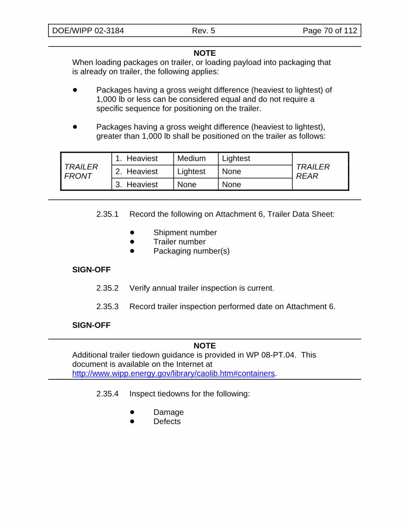
DOE/WIPP 02-3184 Rev. 5 Page 70 of 112
NOTEWhen loading packages on trailer, or loading payload into packaging thatis already on trailer, the following applies:
! Packages having a gross weight difference (heaviest to lightest) of1,000 lb or less can be considered equal and do not require aspecific sequence for positioning on the trailer.
! Packages having a gross weight difference (heaviest to lightest),greater than 1,000 lb shall be positioned on the trailer as follows:
TRAILERFRONT
1. Heaviest Medium LightestTRAILERREAR2. Heaviest Lightest None
3. Heaviest None None
2.35.1 Record the following on Attachment 6, Trailer Data Sheet:
! Shipment number! Trailer number! Packaging number(s)
SIGN-OFF
2.35.2 Verify annual trailer inspection is current.
2.35.3 Record trailer inspection performed date on Attachment 6.
SIGN-OFF
NOTEAdditional trailer tiedown guidance is provided in WP 08-PT.04. Thisdocument is available on the Internet athttp://www.wipp.energy.gov/library/caolib.htm#containers.
2.35.4 Inspect tiedowns for the following:
! Damage! Defects
DOE/WIPP 02-3184 Rev. 5 Page 71 of 112
2.35.5 IF TRUPACT-II was removed for unloading operations, THEN perform the following:
[ A ] Position transport trailer in designated area.
[ B ] Lower trailer jacks (landing gear) ensuring trailer is level.
[ C ] Install wheel chocks.
[ D ] Install jack stands on freestanding trailers.
CAUTION
Tip-back beyond level may damage package exterior surface.
[ E ] Transport packaging to transport trailer.
[ F ] Load packaging designated for position #1 onto trailer withvent port on driver side of trailer.
[ G ] If applicable, load packaging designated for position #2onto trailer with vent port on driver side of trailer.
[ H ] If applicable, load packaging designated for position #3onto trailer with vent port on driver side of trailer.
NOTEAdditional trailer tiedown guidance is provided in WP 08-PT.04. This document is available on the Internet athttp://www.wipp.energy.gov/library/caolib.htm#containers.
[ I ] Install four tiedown assemblies for each packaging loadedon trailer.
[ J ] Install packaging forklift pocket access covers.
2.35.6 Record packaging serial number(s) and weights onAttachment 6.
SIGN-OFF
2.35.7 Record total weight of all loaded packaging as payload weight onAttachment 6.
SIGN-OFF
DOE/WIPP 02-3184 Rev. 5 Page 72 of 112
2.35.8 Verify shipment is in compliance with 49 CFR 172, Subpart D,Subpart E, and Subpart F and initial Attachment 6.
SIGN-OFF
2.35.9 Complete information transfer to shipping documents as requiredfor the specific shipment.
2.35.10 Verify shipping papers are in accordance with 49 CFR 172,Subpart C, and initial Attachment 6.
SIGN-OFF
2.35.11 Initial for trailer loading complete on Attachment 6.
SIGN-OFF
2.35.12 Supervisor, review/validate entries and sign Attachment 6.
SIGN-OFF
3.0 ABNORMAL OPERATIONS
NOTEWIPP Packaging Maintenance Engineer shall be contacted whenperforming Subsections 3.1, 3.2, or 3.3.
3.1 Empty ICV Assembly Removal
3.1.1 Verify ICV lid has been installed and locked.
3.1.2 Mark ICV and OCV with match lines using a low-chloride marker. (These marks will be used to orient the ICV in the OCV duringreinstallation.)
CAUTION
Operator shall verify two ACGLF counterweights are at 180 degrees and000 (+2 degrees) degrees respectively.
3.1.3 Attach ACGLF to ICV lid.
3.1.4 If annulus foam ring is present, remove and set aside for lateruse.
DOE/WIPP 02-3184 Rev. 5 Page 73 of 112
CAUTION
Load cell reading MUST NOT exceed 5,000 lb when weight of ACGLF iszeroed out, OR 7,500 lb when weight of ACGLF is included.
3.1.5 Remove empty ICV assembly from OCV body using crane andACGLF.
NOTEIf required by site-specific policy to ensure personnel safety, RCT shallsurvey OCV interior for radiation/contamination BEFORE initiating OCVinspection process.
3.1.6 Inspect visually for presence of water in bottom of OCV.
3.1.7 If freestanding water is NOT observed in bottom of OCV body,GO TO Step 3.1.11.
CAUTION
Operator shall obtain protective clothing and equipment in accordancewith site Safety Manual before entering OCV cavity. Operator also shallenter the OCV cavity using precautions to preclude damage to OCV bodysealing flange.
3.1.8 Use wet/dry vacuum and/or absorbent materials to removefreestanding water.
NOTECleaning and waste materials shall be managed according to site wastemanagement procedures.
3.1.9 Remove equipment and exit OCV cavity using precautions not todamage OCV body sealing flange.
3.1.10 Verify OCV is free of standing water.
DOE/WIPP 02-3184 Rev. 5 Page 74 of 112
CAUTION
Operator shall verify two ACGLF counterweights are at 180 degrees and000 degrees (+ 2 degrees) respectively.
NOTEWhen Step 3.1.11 is complete, ICV vent port should be within one foot ofOCV vent port and the ICV should be sitting vertically within the OCV(i.e., not leaning to the side).
3.1.11 Reinstall ICV assembly into OCV body using crane and ACGLF.
3.1.12 If annulus debris seal was removed in Step 3.1.4, reinstallannulus debris seal.
3.2 Using Heat Guns to Remove Stuck Lids
3.2.1 Heat ICV or OCV lid O-rings (as necessary) for up to 1 hourusing heat guns.
CAUTION
Operator shall verify two ACGLF counterweights are at 180 degrees and000 degrees (+ 2 degrees) respectively.
CAUTION
When lifting ICV lid, load cell reading MUST NOT exceed 5,000 lb whenweight of ACGLF is zeroed out, OR 7,500 lb when weight of ACGLF isincluded.
CAUTION
When lifting OCA lid, load cell reading MUST NOT exceed 7,500 lb whenweight of ACGLF is zeroed out, OR 10,000 lb when weight of ACGLF isincluded.
3.2.2 Attempt to raise lid using the slowest possible speed.
3.2.3 Raise lid as directed by RCT and RETURN TO normaloperations.
DOE/WIPP 02-3184 Rev. 5 Page 75 of 112
3.3 Pressurizing with Nitrogen or Compressed Air to Remove Stuck Lids
3.3.1 Obtain the following:
! Nitrogen bottle with $ 500 lb pressure or other air sourcecapable of being regulated in 1-psi increments
! Pressure Assembly (Figure 3.1, Flow Diagram forNitrogen Bottle/Compressed Air ICV/OCA LidPressurization)
! If not already installed, ICV/OCV vent port tools, asapplicable
3.3.2 Perform the following for compressed air or nitrogen:
[ A ] Assemble Pressure Assembly (see Figure 3.1 for exampleof a pressure assembly).
[ B ] If not already installed, install vent port tool hand-tight.
[ C ] Connect Pressure Assembly to quick disconnect on ventport tool.
[ D ] Close valve V-1.
[ E ] Close valve V-2.
[ F ] Verify supply valve is closed.
[ G ] Verify back pressure relief valve is fully backed-off.
[ H ] Verify pressure regulator is fully backed off.
[ I ] Connect supply line and regulator to nitrogen-bottle orcompressed air source.
[ J ] Open supply valve and adjust N2 or air supply regulator toa maximum of 150 psig.
[ K ] Adjust R1 to about 2.1 psig.
[ L ] Adjust R2 until it begins to relieve pressure.
[ M ] Adjust R1 to fully backed off.
[ N ] Bleed briefly through V-1.
[ O ] Adjust R1 to about 1 psig.
DOE/WIPP 02-3184 Rev. 5 Page 76 of 112
3.3.3 Verify counterweights are at 180 degrees and 000 degrees.
WARNING
The ICV or OCV should not be pressurized above 2 psi to avoid personnelinjury. A loaded ICV MUST NOT be pressurized unless precautions aretaken to prevent possible contamination when lid is raised.
CAUTION
When lifting ICV lid, load cell reading MUST NOT exceed 5,000 lb whenweight of ACGLF is zeroed out, OR 7,500 lb when weight of ACGLF isincluded.
CAUTION
When lifting OCV lid, load cell reading MUST NOT exceed 7,500 lb whenweight of ACGLF is zeroed out, OR 10,000 lb when weight of ACGLF isincluded.
3.3.4 Attempt to lift lid using crane at the slowest rate possible whilemonitoring load cell.
3.3.5 Perform the following while attempting to lift lid with crane:
[ A ] Throttle valve V-2, keeping pressure # 2 psi.
[ B ] When lid becomes loose, close V-2.
[ C ] Close supply valve.
[ D ] Open V-1 to depressurize assembly.
[ E ] Disconnect supply line from pressure assembly.
[ F ] Disconnect pressure assembly from vent port tool.
[ G ] Disconnect vent port tool and survey tool if applicable.
[ H ] Disconnect supply line and regulator from nitrogen bottleor compressed air source.
3.3.6 Raise lid as directed by RCT AND continue with normaloperations.
DOE/WIPP 02-3184 Rev. 5 Page 77 of 112
3.3.7 IF after pressurizing to 2 psi lid still does not lift, THEN contact the WIPP M&O Contractor CH PackagingMaintenance Engineer.
3.4 Venting
NOTEIn the event a sealed package cannot be shipped within the time frame setforth in the TRUPACT-II or HalfPACT Packaging SAR, the package mustbe vented.
3.4.1 IF venting is required,THEN perform applicable Subsections 2.22, OCA Lid Removal, and 2.23, ICV Lid Removal.
3.4.2 Wait three minutes.
3.4.3 GO TO Subsection 2.17, reinstall lids using Subsections 2.17and 2.18.
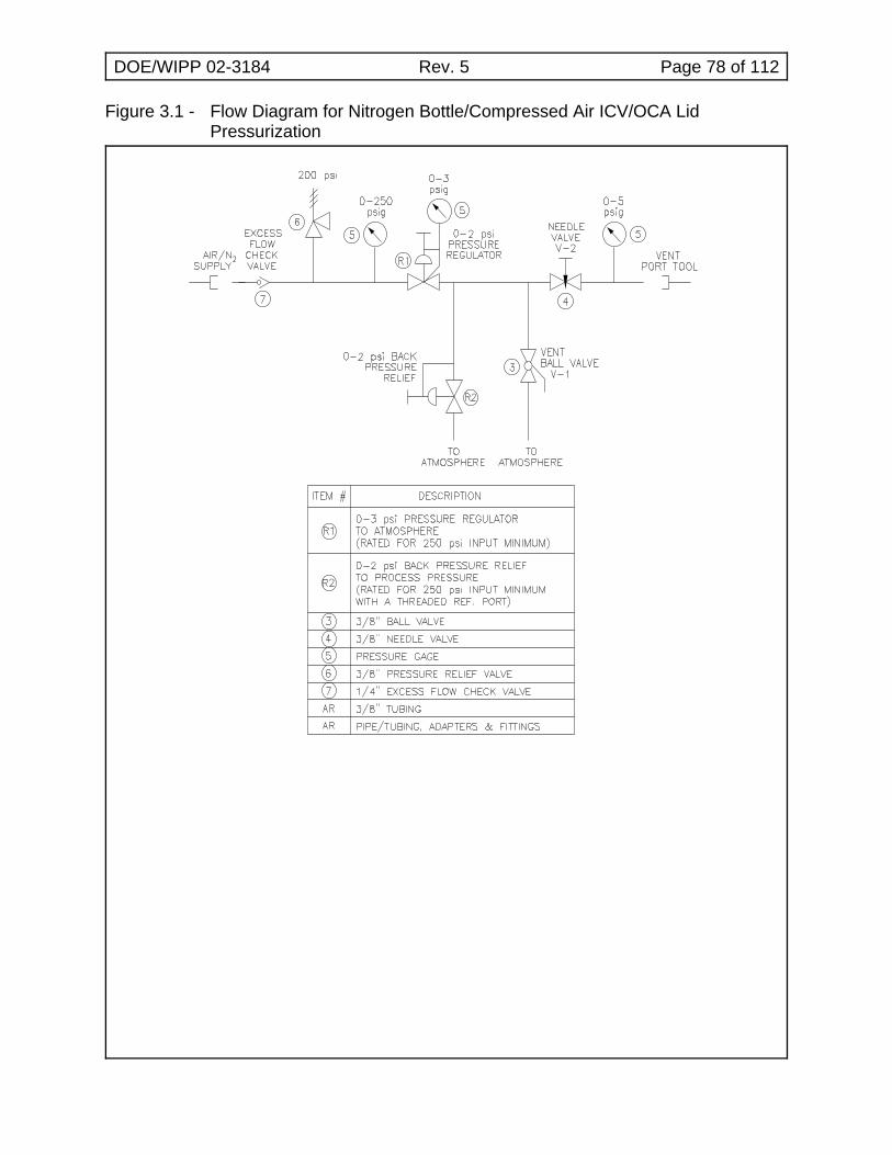
DOE/WIPP 02-3184 Rev. 5 Page 78 of 112
Figure 3.1 - Flow Diagram for Nitrogen Bottle/Compressed Air ICV/OCA LidPressurization
DOE/WIPP 02-3184 Rev. 5 Page 79 of 112
4.0 PRESHIPMENT LEAKAGE RATE TESTING
4.1 Basic Information
4.1.1 Introduction - This procedure provides instructions for performingICV and OCV preshipment leakage rate tests on the followingpackaging seals, using a nondestructive helium (He) leak test:
! ICV upper main O-ring seal! ICV outer vent port plug seal O-ring! OCV upper main O-ring seal! OCV vent port plug seal O-ring
4.1.2 References
! U.S. Department of Energy, Safety Analysis Report for theTRUPACT-II Shipping Package
! U.S. Department of Energy, Safety Analysis Report for theHalfPACT Shipping Package
! DOE/WIPP 02-3183, CH Packaging Program Guidance
! DOE/WIPP 02-3185, CH Packaging Maintenance Manual
! ANSI N 14.5, 1997, Radioactive Materials Leakage Testson Packages for Shipment
! ASNT, Recommended Practice No. SNT-TC-1A, June1980
! WP 13-RP.01, Test Report for WP 13-QA1082 ProcedureQualification
4.1.3 Equipment
MEASURING AND TEST EQUIPMENT
! Varian 938-41 or 959 Helium Leak Detector with7 to 14 cfm mechanical vacuum pump
! Roughing pump
! Helium leak standard for calibrating leak detector
! Pressure/vacuum gauge, 30-in. Hg to 30 psig
! Temperature measuring device, 32EF to 120EF(0EC to 50EC)
DOE/WIPP 02-3184 Rev. 5 Page 80 of 112
! Ambient atmospheric pressure measuring device
! Watch or stopwatch, digital or sweep second hand (nocalibration required)
! Torque wrench with 10 to 65 lb-in. range
! Torque wrench with 30 to 50 lb-ft range
SPECIAL TEST EQUIPMENT
! ICV/OCV vent port plug removal/pressure relief tools
! ICV/OCV vent port plug/cover removal and installationtools
! ICV/OCV seal leak check tools
! ICV/OCV leak detection tools
! Miscellaneous hardware and test connections
CONSUMABLE MATERIALS
! Welding grade helium (with certificate of conformance[C of C])|
! Argon or nitrogen (purge gas)
4.1.4 Precautions and Limitations
The following leak test procedure may be used, or each usermay develop and qualify a procedure in accordance with theguidelines of ANSI N14.5, 1997. Sites that opt to qualify theirown leak test procedure must submit procedure qualificationrecord and procedure to Site [email protected], for approval.
! Leak testing of CH packaging shall be performed bypersonnel qualified in accordance with the AmericanSociety for Nondestructive Testing PracticeNo. SNT-TC-1A, June 1980 edition and supplement.
! This procedure is qualified per WP 13-RP.01, Test Reportfor WP 13-QA1082 Procedure Qualification for theVarian 938-41 and 959 MSLD and test line configurationdefined in that report. CH packaging users adopting thisleak test must not deviate from the test configuration(s)used to qualify the procedure.
DOE/WIPP 02-3184 Rev. 5 Page 81 of 112
! The helium leak detector shall be calibrated to a minimumsensitivity of 1.3×10⁻⁷ standard cubic centimeters persecond (scc/s) He.
! The leakage rate acceptance criteria of < 1.0×10⁻⁷ scc/s ofair equates to a leakage rate of < 2.6×10⁻⁷ scc/s He. TheHe leakage rate is only valid for a component of > 4.4EC. The acceptable He leakage rate increases withtemperature, but as a conservative measure, anacceptance criteria of < 2.6×10⁻⁷ scc/s He will be used.
4.1.5 Prerequisite Actions
! Verify air flow through leak check and leak detection tools.
! Verify packaging surface is free of contaminates thatmight mask a leak. The interior and exterior surfacesshall be dry.
4.2 ICV Upper Main O-Ring Seal
4.2.1 Record the following on Attachment 7, ICV PreshipmentLeakage-Rate Test Data Sheet:
! ICV body serial number (S/N)! ICV lid S/N! Date of leak test! Helium leak detector S/N and model! Pressure/vacuum gauge S/N and calibration due date! Thermometer S/N and calibration due date! Torque wrench S/Ns and calibration due dates! Standard leak S/N and calibration due date! Barometer S/N and calibration due date! Helium source with C of C connected to backfill system|
SIGN-OFF
NOTESteps 4.2.15 through 4.2.19 may be performed in parallel with Steps 4.2.2through 4.2.14.
4.2.2 Measure ICV surface temperature.
4.2.3 If temperature is less than 4.4EC, stop test until surfacetemperature > 4.4EC.
4.2.4 Record surface temperature on Attachment 7.
SIGN-OFF
DOE/WIPP 02-3184 Rev. 5 Page 82 of 112
4.2.5 Verify outer vent port plug is retracted into ICV vent port plugremoval/pressure relief tool.
4.2.6 Install ICV vent port tool into ICV vent port.
4.2.7 Attach vacuum pump assembly and He gas supply to vent porttool (see Figure 4.1, ICV Main O-Ring Seal Test).
4.2.8 Open isolation valve to vacuum pump.
4.2.9 Start vacuum pump.
4.2.10 Record ambient atmospheric pressure (Patm) on Attachment 7.
SIGN-OFF
4.2.11 Evacuate ICV vent port cavity to 90% vacuum (90% ofatmospheric pressure) or better.
4.2.12 Record vacuum reading (V1) on Attachment 7.
SIGN-OFF
4.2.13 Calculate He concentration correction factor (CCF) as follows:
CCF = Patm V1
4.2.14 Record CCF on Attachment 7.
SIGN-OFF
4.2.15 Perform pretest calibration of leak detector (to the temperature-corrected standard leak value) and record results onAttachment 7.
SIGN-OFF
4.2.16 Install ICV seal leak check tool in ICV seal test port.
4.2.17 Connect leak detector to ICV leak check tool (see Figure 4.1).
4.2.18 Verify isolation valve open.
4.2.19 Evacuate space between O-ring seals through ICV seal test port.
4.2.20 Close vacuum pump isolation valve AND stop vacuum pump.
DOE/WIPP 02-3184 Rev. 5 Page 83 of 112
NOTETo measure a > 2.6×10⁻⁷ scc/s He leakage rate, the indicated Hebackground will be allowed to stabilize at 7×10⁻⁷ scc/s He or less andremain below the limit for a minimum of 3 minutes.
4.2.21 Record He background (RB) on Attachment 7.
SIGN-OFF
4.2.22 Open He valve and backfill cavity with He to a pressure slightlygreater than atmospheric pressure (+1 psi, -0 psi).
4.2.23 Close He valve.
4.2.24 Record backfill pressure reading on Attachment 7.
SIGN-OFF
4.2.25 Begin timing for 3-minute dwell time.
4.2.26 Monitor pressure gauge and add He as required to maintain Heatmosphere in the cavity.
NOTEA dwell time of 3 minutes will be used to determine leakage rate of ICVupper main O-ring seal.
4.2.27 Record displayed He reading (RT) after 3-minute dwell time onAttachment 7.
SIGN-OFF
NOTESteps 4.3.1 through 4.3.6 may be performed in parallel withSteps 4.2.28 through 4.2.35.
4.2.28 Remove test assembly from leak detector.
4.2.29 Install calibrated leak to leak detector.
4.2.30 Perform post-test calibration deviation check of leak detector andrecord results on Attachment 7.
SIGN-OFF
4.2.31 Calculate the ICV upper main O-ring seal leakage rate using thecorrect condition below and record on Attachment 7:
DOE/WIPP 02-3184 Rev. 5 Page 84 of 112
NOTEIf the He background (RB) is greater than the displayed He reading at theend of dwell time (RT), the value of (RT) will be substituted for the value of(RB) when performing leak rate calculations. If condition [ C ] applies, andthis note is applicable to that condition (ending up with a negativenumber), zero will be used as the leakage rate.
NOTEThe difference between displayed He reading (DR) with standard leakinstalled, including Zero Reading Variance (if applicable) and TemperatureCorrection Value (TC), is used to determine post-test calibration deviation. Additional guidance is provided in DOE/WIPP 02-3183, Section 4.2.9.
[ A ] If there is no difference in the Temperature CorrectionValue (TC) from the displayed He reading with standardleak installed (DR), use the following equation: subtractthe He background at the start of test (RB) from thedisplayed He reading at end of test (RT). The leakagerate is (RT – RB) × CCF. This equals the leakage rate forthis segment of the test.
[ B ] If Temperature Correction Value (TC) is LESS than thedisplayed He reading with standard leak installed (DR),use the following calculation: (RT + calibration deviation –RB) × CCF. This equals the leakage rate for this segmentof the test under this condition of recalibration.
[ C ] If Temperature Correction Value (TC) is MORE than thedisplayed He reading with standard leak installed (DR),use the following calculation: (RT - calibration deviation –RB) × CCF. This equals the leakage rate for this segmentof the test under this condition of recalibration.
SIGN-OFF
4.2.32 If the acceptance criterion is satisfied (< 2.6×10⁻⁷ scc/s of He),this segment of the test procedure is complete.
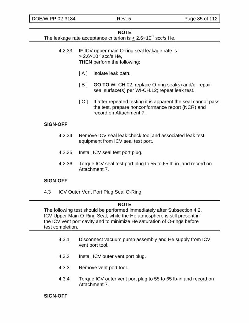
DOE/WIPP 02-3184 Rev. 5 Page 85 of 112
NOTEThe leakage rate acceptance criterion is < 2.6×10⁻⁷ scc/s He.
4.2.33 IF ICV upper main O-ring seal leakage rate is> 2.6×10⁻⁷ scc/s He,THEN perform the following:
[ A ] Isolate leak path.
[ B ] GO TO WI-CH.02, replace O-ring seal(s) and/or repairseal surface(s) per WI-CH.12; repeat leak test.
[ C ] If after repeated testing it is apparent the seal cannot passthe test, prepare nonconformance report (NCR) andrecord on Attachment 7.
SIGN-OFF
4.2.34 Remove ICV seal leak check tool and associated leak testequipment from ICV seal test port.
4.2.35 Install ICV seal test port plug.
4.2.36 Torque ICV seal test port plug to 55 to 65 lb-in. and record onAttachment 7.
SIGN-OFF
4.3 ICV Outer Vent Port Plug Seal O-Ring
NOTEThe following test should be performed immediately after Subsection 4.2,ICV Upper Main O-Ring Seal, while the He atmosphere is still present inthe ICV vent port cavity and to minimize He saturation of O-rings beforetest completion.
4.3.1 Disconnect vacuum pump assembly and He supply from ICVvent port tool.
4.3.2 Install ICV outer vent port plug.
4.3.3 Remove vent port tool.
4.3.4 Torque ICV outer vent port plug to 55 to 65 lb-in and record onAttachment 7.
SIGN-OFF
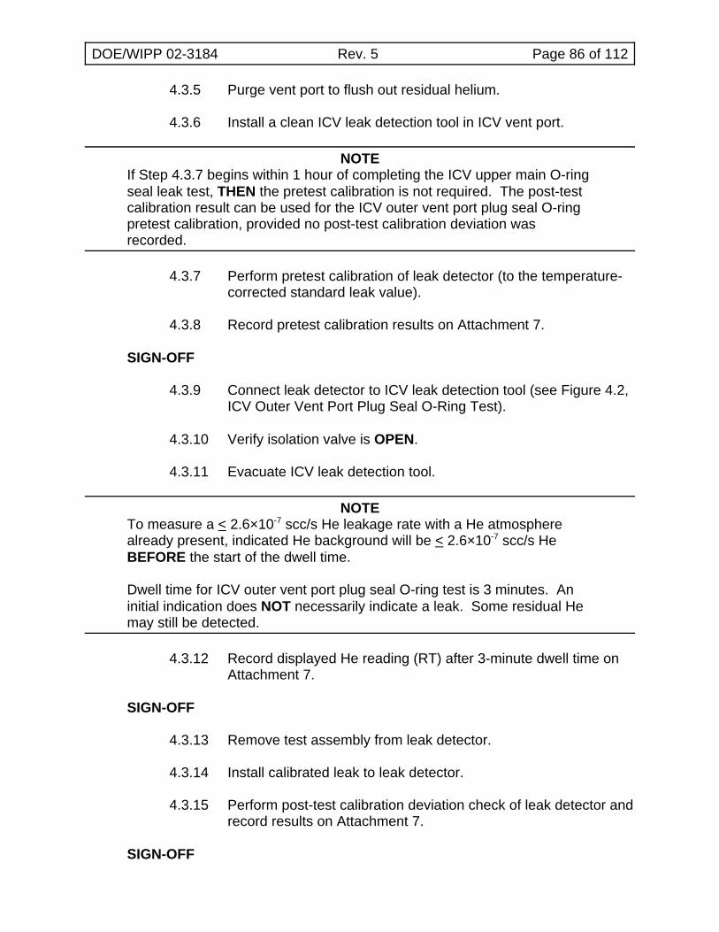
DOE/WIPP 02-3184 Rev. 5 Page 86 of 112
4.3.5 Purge vent port to flush out residual helium.
4.3.6 Install a clean ICV leak detection tool in ICV vent port.
NOTEIf Step 4.3.7 begins within 1 hour of completing the ICV upper main O-ringseal leak test, THEN the pretest calibration is not required. The post-testcalibration result can be used for the ICV outer vent port plug seal O-ringpretest calibration, provided no post-test calibration deviation wasrecorded.
4.3.7 Perform pretest calibration of leak detector (to the temperature-corrected standard leak value).
4.3.8 Record pretest calibration results on Attachment 7.
SIGN-OFF
4.3.9 Connect leak detector to ICV leak detection tool (see Figure 4.2,ICV Outer Vent Port Plug Seal O-Ring Test).
4.3.10 Verify isolation valve is OPEN.
4.3.11 Evacuate ICV leak detection tool.
NOTETo measure a < 2.6×10⁻⁷ scc/s He leakage rate with a He atmospherealready present, indicated He background will be < 2.6×10⁻⁷ scc/s HeBEFORE the start of the dwell time.
Dwell time for ICV outer vent port plug seal O-ring test is 3 minutes. Aninitial indication does NOT necessarily indicate a leak. Some residual Hemay still be detected.
4.3.12 Record displayed He reading (RT) after 3-minute dwell time onAttachment 7.
SIGN-OFF
4.3.13 Remove test assembly from leak detector.
4.3.14 Install calibrated leak to leak detector.
4.3.15 Perform post-test calibration deviation check of leak detector andrecord results on Attachment 7.
SIGN-OFF
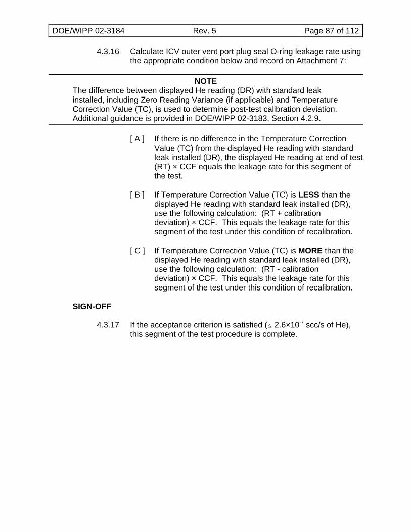
DOE/WIPP 02-3184 Rev. 5 Page 87 of 112
4.3.16 Calculate ICV outer vent port plug seal O-ring leakage rate usingthe appropriate condition below and record on Attachment 7:
NOTEThe difference between displayed He reading (DR) with standard leakinstalled, including Zero Reading Variance (if applicable) and TemperatureCorrection Value (TC), is used to determine post-test calibration deviation. Additional guidance is provided in DOE/WIPP 02-3183, Section 4.2.9.
[ A ] If there is no difference in the Temperature CorrectionValue (TC) from the displayed He reading with standardleak installed (DR), the displayed He reading at end of test(RT) × CCF equals the leakage rate for this segment ofthe test.
[ B ] If Temperature Correction Value (TC) is LESS than thedisplayed He reading with standard leak installed (DR),use the following calculation: (RT + calibrationdeviation) × CCF. This equals the leakage rate for thissegment of the test under this condition of recalibration.
[ C ] If Temperature Correction Value (TC) is MORE than thedisplayed He reading with standard leak installed (DR),use the following calculation: (RT - calibrationdeviation) × CCF. This equals the leakage rate for thissegment of the test under this condition of recalibration.
SIGN-OFF
4.3.17 If the acceptance criterion is satisfied (# 2.6×10⁻⁷ scc/s of He),this segment of the test procedure is complete.
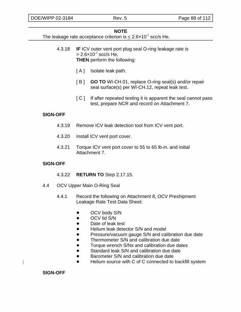
DOE/WIPP 02-3184 Rev. 5 Page 88 of 112
NOTEThe leakage rate acceptance criterion is < 2.6×10⁻⁷ scc/s He.
4.3.18 IF ICV outer vent port plug seal O-ring leakage rate is> 2.6×10⁻⁷ scc/s He,THEN perform the following:
[ A ] Isolate leak path.
[ B ] GO TO WI-CH.01, replace O-ring seal(s) and/or repairseal surface(s) per WI-CH.12, repeat leak test.
[ C ] If after repeated testing it is apparent the seal cannot passtest, prepare NCR and record on Attachment 7.
SIGN-OFF
4.3.19 Remove ICV leak detection tool from ICV vent port.
4.3.20 Install ICV vent port cover.
4.3.21 Torque ICV vent port cover to 55 to 65 lb-in. and initialAttachment 7.
SIGN-OFF
4.3.22 RETURN TO Step 2.17.15.
4.4 OCV Upper Main O-Ring Seal
4.4.1 Record the following on Attachment 8, OCV PreshipmentLeakage Rate Test Data Sheet:
! OCV body S/N! OCV lid S/N! Date of leak test! Helium leak detector S/N and model! Pressure/vacuum gauge S/N and calibration due date! Thermometer S/N and calibration due date! Torque wrench S/Ns and calibration due dates! Standard leak S/N and calibration due date! Barometer S/N and calibration due date! Helium source with C of C connected to backfill system|
SIGN-OFF
DOE/WIPP 02-3184 Rev. 5 Page 89 of 112
NOTESteps 4.4.12 through 4.4.17 may be performed in parallel with Steps 4.4.2through 4.4.11.
4.4.2 Measure OCV surface temperature and record on Attachment 8.
SIGN-OFF
4.4.3 If temperature is less than 4.4EC, stop test until surfacetemperature > 4.4EC.
4.4.4 Attach vacuum pump assembly and He gas supply to vent porttool (see Figure 4.3, OCV Main O-Ring Seal Test).
4.4.5 Open isolation valve to vacuum pump.
4.4.6 Start vacuum pump.
4.4.7 Record ambient atmospheric pressure (Patm) on Attachment 8.
SIGN-OFF
4.4.8 Evacuate OCV cavity to 90% vacuum (90% of atmosphericpressure) or better.
4.4.9 Record vacuum reading (V1) on Attachment 8.
SIGN-OFF
4.4.10 Calculate He concentration correction factor as follows:
CCF = Patm V1
4.4.11 Record CCF on Attachment 8.
SIGN-OFF
4.4.12 Perform pretest calibration of leak detector (to the temperature-corrected standard leak value).
4.4.13 Record pretest calibration results on Attachment 8.
SIGN-OFF
4.4.14 Install OCV seal leak check tool in OCV seal test port.
4.4.15 Connect leak detector to OCV leak check tool (see Figure 4.3).
DOE/WIPP 02-3184 Rev. 5 Page 90 of 112
4.4.16 Verify isolation valve open.
4.4.17 Evacuate space between O-ring seals through OCV seal testport.
4.4.18 Close vacuum pump isolation valve AND stop vacuum pump.
NOTETo measure a 2.6×10⁻⁷ scc/s He leakage rate, the indicated Hebackground will be allowed to stabilize at < 7×10⁻⁷ scc/s He and remainbelow the limit for a minimum of 3 minutes.
4.4.19 Record He background (RB) on Attachment 8.
SIGN-OFF
4.4.20 Open He valve and backfill OCV cavity with He to a pressureslightly greater than atmospheric pressure (+1 psi, -0 psi).
4.4.21 Close He valve.
4.4.22 Record backfill pressure reading on Attachment 8.
SIGN-OFF
4.4.23 Begin timing for 3-minute dwell time.
4.4.24 Monitor pressure gauge and add He as required to maintain Heatmosphere in the cavity.
NOTEA dwell time of 3 minutes will be used to determine leakage rate of OCVupper main O-ring seal.
4.4.25 Record displayed He reading (RT) after 3-minute dwell time onAttachment 8.
SIGN-OFF
NOTESteps 4.5.1 through 4.5.6 may be performed in parallel with Steps 4.4.26through 4.4.34.
4.4.26 Remove test assembly from leak detector.
4.4.27 Install calibrated leak to leak detector.
DOE/WIPP 02-3184 Rev. 5 Page 91 of 112
4.4.28 Perform post-test calibration deviation check of leak detector andrecord results on Attachment 8.
SIGN-OFF
4.4.29 Calculate OCV main O-ring seal leakage rate using theappropriate condition below and record on Attachment 8.
NOTEIf the He background (RB) is greater than the displayed He reading at theend of dwell time (RT), the value of (RT) will be substituted for the value of(RB) when performing leak rate calculations. If condition [ C ] applies, andthis note is applicable to that condition (ending up with a negativenumber), zero will be used as the leakage rate.
NOTEThe difference between displayed He reading (DR) with standard leakinstalled, including Zero Reading Variance (if applicable) and TemperatureCorrection Value (TC), is used to determine post-test calibration deviation. Additional guidance is provided in DOE/WIPP 02-3183, Section 4.2.9.
[ A ] If there is no difference in the Temperature CorrectionValue (TC) from the displayed He reading with standardleak installed (DR), use the following equation: subtractthe He background at the start of test (RB) from thedisplayed He reading at end of test (RT). The leakagerate is (RT – RB) × CCF. This equals the leakage rate forthis segment of the test.
[ B ] If Temperature Correction Value (TC) is LESS than thedisplayed He reading with standard leak installed (DR),use the following calculation: (RT + calibration deviation –RB) × CCF. This equals the leakage rate for this segmentof the test under this condition of recalibration.
[ C ] If Temperature Correction Value (TC) is MORE than thedisplayed He reading with standard leak installed (DR),use the following calculation: (RT - calibration deviation –RB) × CCF. This equals the leakage rate for this segmentof the test under this condition of recalibration.
SIGN-OFF
4.4.30 If acceptance criterion is satisfied (< 2.6×10⁻⁷ scc/s of He), thissegment of the test procedure is complete.
DOE/WIPP 02-3184 Rev. 5 Page 92 of 112
NOTEThe leakage rate acceptance criterion is < 2.6×10⁻⁷ scc/s He.
4.4.31 IF OCV main O-ring seal leakage rate is > 2.6×10⁻⁷ scc/s He,THEN perform the following:
[ A ] Isolate leak path.
[ B ] GO TO WI-CH.02, replace O-ring seal(s) and/or repairseal surface(s) per WI-CH.12, and repeat leak test.
[ C ] If after repeated testing it is apparent the seal cannot passtest, prepare NCR and record on Attachment 8.
SIGN-OFF
4.4.32 Remove OCV seal leak check tool and associated leak testequipment from OCV seal test port.
4.4.33 Install OCV seal test port plug.
4.4.34 Torque OCV seal test port plug to 55 to 65 lb-in and record onAttachment 8.
SIGN-OFF
4.5 OCV Vent Port Plug Seal O-Ring
NOTEThe following test should be performed immediately after Subsection 4.4,OCV Upper Main O-Ring Seal, while the He atmosphere is still present inthe OCV cavity and to minimize He saturation of the O-rings before testcompletion.
4.5.1 Disconnect vacuum pump assembly and He supply from OCVvent port tool.
4.5.2 Install OCV vent port plug.
4.5.3 Remove vent port tool.
4.5.4 Torque OCV vent port plug to 55 to 65 lb-in. and record onAttachment 8.
SIGN-OFF
4.5.5 Purge vent port to flush out residual helium.
DOE/WIPP 02-3184 Rev. 5 Page 93 of 112
4.5.6 Install a clean OCV leak detection tool in OCV vent port.
NOTEIf Step 4.5.7 begins within 1 hour of completing the OCV upper mainO-ring seal leak test, THEN the pretest calibration is not required. Thepost-test calibration result can be used for the OCV vent port plug sealO-ring pretest calibration, provided no post-test calibration deviation wasrecorded.
4.5.7 Perform pretest calibration of leak detector (to the temperature-corrected standard leak value).
4.5.8 Record pretest calibration results on Attachment 8.
SIGN-OFF
4.5.9 Connect leak detector to OCV leak detection tool (seeFigure 4.4, OCV Vent Port Plug Seal O-Ring Test).
4.5.10 Verify isolation valve is OPEN.
4.5.11 Evacuate OCV leak detection tool.
NOTETo measure a < 2.6×10⁻⁷ scc/s He leakage rate with a He atmospherealready present, the indicated He background will be < 2.6×10⁻⁷ scc/s Hebefore the start of the dwell time.
Dwell time for OCV vent port plug seal O-ring test is 3 minutes. An initialindication does NOT necessarily indicate a leak. Some residual He maystill be detected.
4.5.12 Record displayed He reading (RT) after 3-minute dwell time onAttachment 8.
SIGN-OFF
4.5.13 Remove test assembly from leak detector.
4.5.14 Install calibrated leak to leak detector.
4.5.15 Perform post-test calibration deviation check of leak detector andrecord results on Attachment 8.
SIGN-OFF
DOE/WIPP 02-3184 Rev. 5 Page 94 of 112
4.5.16 Calculate OCV vent port plug seal O-ring leakage rate using theappropriate condition below and record on Attachment 8:
NOTEThe difference between displayed He reading (DR) with standard leakinstalled, including Zero Reading Variance (if applicable) and TemperatureCorrection Value (TC), is used to determine post-test calibration deviation. Additional guidance is provided in DOE/WIPP 02-3183, Section 4.2.9.
[ A ] If there is no difference in the Temperature CorrectionValue (TC) from the displayed He reading with standardleak installed (DR), the displayed He reading at end of test(RT) × CCF equals the leakage rate for this segment ofthe test.
[ B ] If Temperature Correction Value (TC) is LESS than thedisplayed He reading with standard leak installed (DR),use the following calculation: (RT + calibrationdeviation) × CCF. This equals the leakage rate for thissegment of the test under this condition of recalibration.
[ C ] If Temperature Correction Value (TC) is MORE than thedisplayed He reading with standard leak installed (DR),use the following calculation: (RT – calibrationdeviation) × CCF. This equals the leakage rate for thissegment of the test under this condition of recalibration.
SIGN-OFF
4.5.17 If acceptance criterion is satisfied (< 2.6×10⁻⁷ scc/s of He), thissegment of the test procedure is complete.
NOTEThe leakage rate acceptance criterion is < 2.6×10⁻⁷ scc/s He.
4.5.18 IF OCV vent port plug seal O-ring leakage rate is> 2.6×10⁻⁷ scc/s He,THEN perform the following:
[ A ] Isolate leak path.
[ B ] GO TO WI-CH.01, replace O-ring seal(s) and/or repairseal surface(s) per WI-CH.12, and repeat leak test.
[ C ] If after repeated testing it is apparent the seal cannot passtest, prepare NCR and record on Attachment 8.
SIGN-OFF
DOE/WIPP 02-3184 Rev. 5 Page 95 of 112
4.5.19 Remove OCV leak detection tool from OCV vent port.
4.5.20 Install OCV vent port cover.
4.5.21 Torque OCV vent port cover to 55 to 65 lb-in. and record onAttachment 8.
SIGN-OFF
4.5.22 Install OCV seal test port thermal plug and access plug.
4.5.23 Torque OCV seal test port access plug to 35 to 45 lb-ft andrecord on Attachment 8.
SIGN-OFF
4.5.24 Install OCV vent port thermal plug and access plug.
4.5.25 Torque OCV vent port access plug to 35 to 45 lb-ft and record onAttachment 8.
SIGN-OFF
4.5.26 RETURN TO Step 2.18.15.
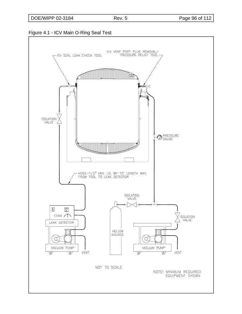
DOE/WIPP 02-3184 Rev. 5 Page 96 of 112
Figure 4.1 - ICV Main O-Ring Seal Test
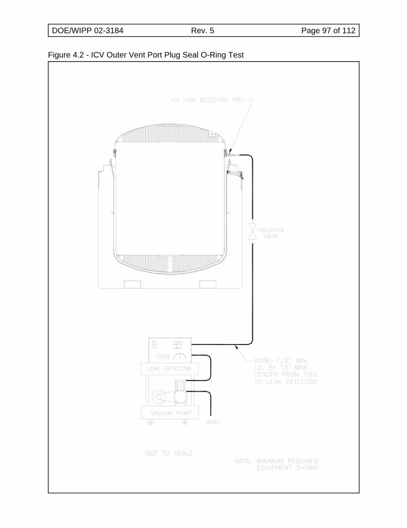
DOE/WIPP 02-3184 Rev. 5 Page 97 of 112
Figure 4.2 - ICV Outer Vent Port Plug Seal O-Ring Test
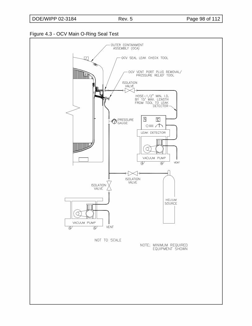
DOE/WIPP 02-3184 Rev. 5 Page 98 of 112
Figure 4.3 - OCV Main O-Ring Seal Test
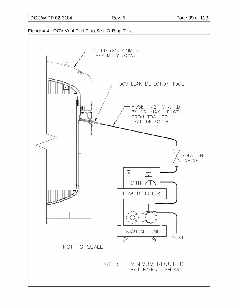
DOE/WIPP 02-3184 Rev. 5 Page 99 of 112
Figure 4.4 - OCV Vent Port Plug Seal O-Ring Test
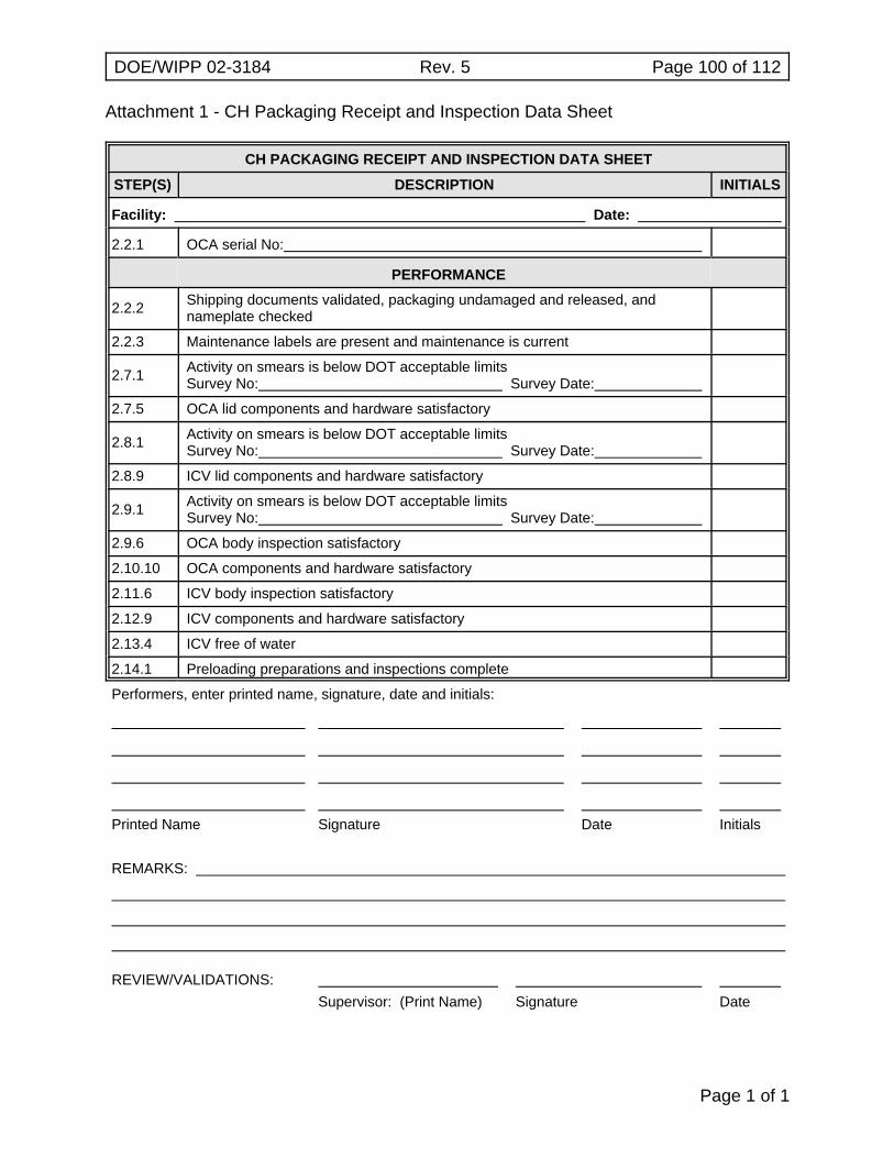
DOE/WIPP 02-3184 Rev. 5 Page 100 of 112
Page 1 of 1
Attachment 1 - CH Packaging Receipt and Inspection Data Sheet
CH PACKAGING RECEIPT AND INSPECTION DATA SHEET
STEP(S) DESCRIPTION INITIALS
Facility: Date:
2.2.1 OCA serial No:
PERFORMANCE
2.2.2 Shipping documents validated, packaging undamaged and released, andnameplate checked
2.2.3 Maintenance labels are present and maintenance is current
2.7.1 Activity on smears is below DOT acceptable limitsSurvey No: Survey Date:
2.7.5 OCA lid components and hardware satisfactory
2.8.1 Activity on smears is below DOT acceptable limitsSurvey No: Survey Date:
2.8.9 ICV lid components and hardware satisfactory
2.9.1 Activity on smears is below DOT acceptable limitsSurvey No: Survey Date:
2.9.6 OCA body inspection satisfactory
2.10.10 OCA components and hardware satisfactory
2.11.6 ICV body inspection satisfactory
2.12.9 ICV components and hardware satisfactory
2.13.4 ICV free of water
2.14.1 Preloading preparations and inspections complete
Performers, enter printed name, signature, date and initials:
Printed Name Signature Date Initials
REMARKS:
REVIEW/VALIDATIONS:Supervisor: (Print Name) Signature Date
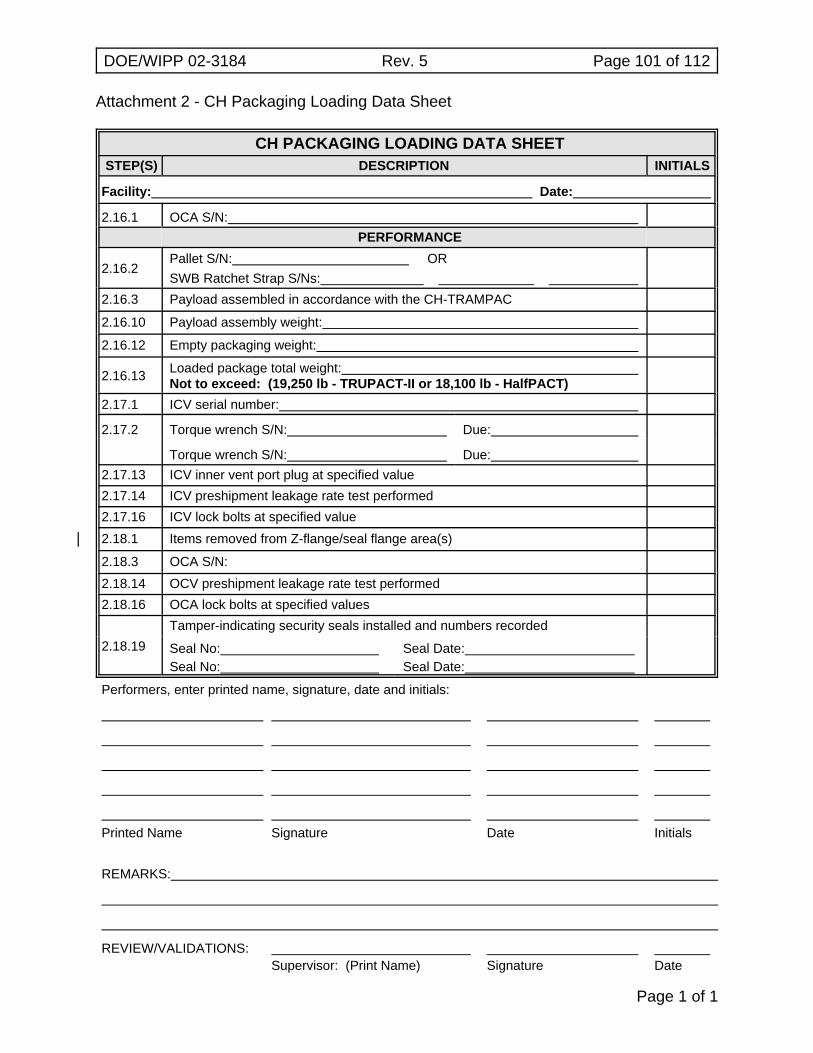
DOE/WIPP 02-3184 Rev. 5 Page 101 of 112
Page 1 of 1
Attachment 2 - CH Packaging Loading Data Sheet
CH PACKAGING LOADING DATA SHEETSTEP(S) DESCRIPTION INITIALS
Facility: Date:
2.16.1 OCA S/N:PERFORMANCE
2.16.2Pallet S/N: ORSWB Ratchet Strap S/Ns:
2.16.3 Payload assembled in accordance with the CH-TRAMPAC
2.16.10 Payload assembly weight:
2.16.12 Empty packaging weight:
2.16.13 Loaded package total weight:Not to exceed: (19,250 lb - TRUPACT-II or 18,100 lb - HalfPACT)
2.17.1 ICV serial number:
2.17.2 Torque wrench S/N: Due:
Torque wrench S/N: Due:2.17.13 ICV inner vent port plug at specified value2.17.14 ICV preshipment leakage rate test performed2.17.16 ICV lock bolts at specified value2.18.1| Items removed from Z-flange/seal flange area(s)|2.18.3 OCA S/N:2.18.14 OCV preshipment leakage rate test performed2.18.16 OCA lock bolts at specified values
2.18.19Tamper-indicating security seals installed and numbers recorded
Seal No: Seal No:
Seal Date: Seal Date:
Performers, enter printed name, signature, date and initials:
Printed Name Signature Date Initials
REMARKS:
REVIEW/VALIDATIONS:Supervisor: (Print Name) Signature Date
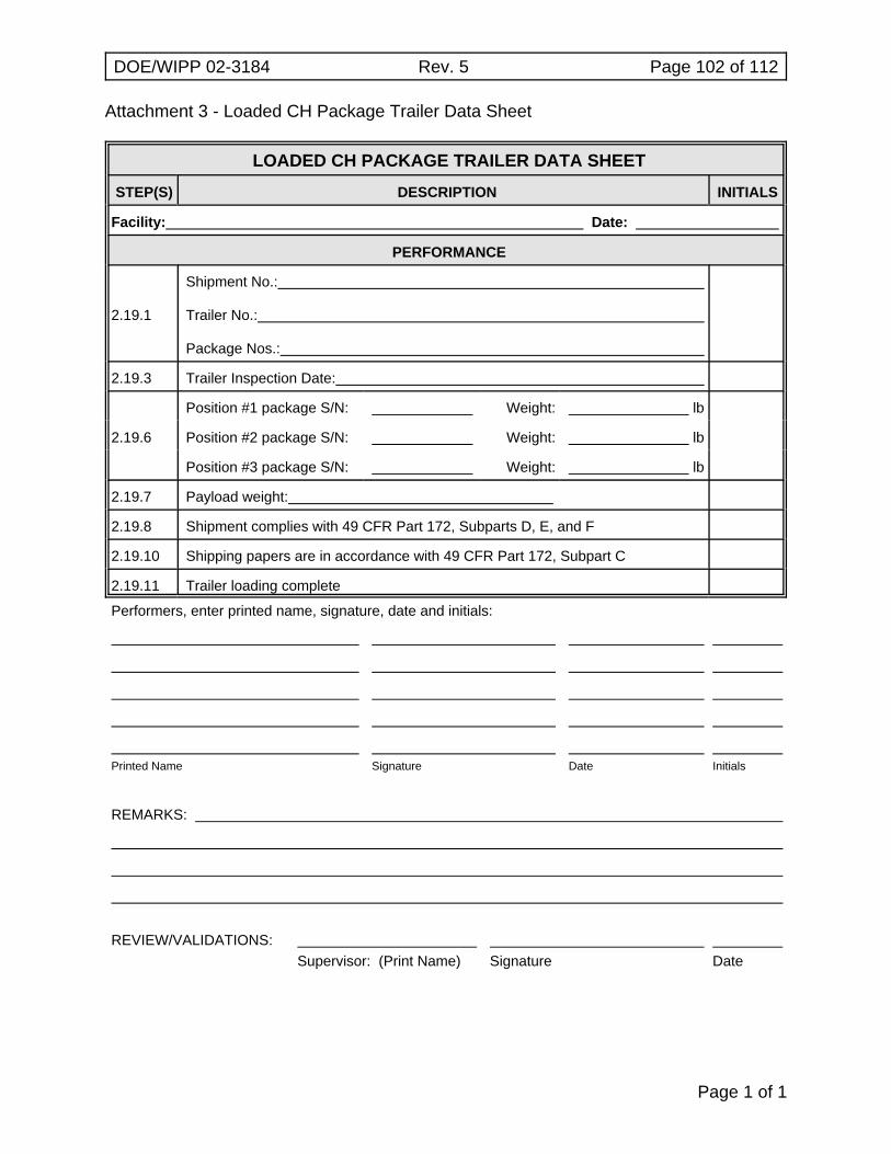
DOE/WIPP 02-3184 Rev. 5 Page 102 of 112
Page 1 of 1
Attachment 3 - Loaded CH Package Trailer Data Sheet
LOADED CH PACKAGE TRAILER DATA SHEET
STEP(S) DESCRIPTION INITIALS
Facility: Date:
PERFORMANCE
2.19.1
Shipment No.:
Trailer No.:
Package Nos.:
2.19.3 Trailer Inspection Date:
2.19.6
Position #1 package S/N: Weight: lb
Position #2 package S/N: Weight: lb
Position #3 package S/N: Weight: lb
2.19.7 Payload weight:
2.19.8 Shipment complies with 49 CFR Part 172, Subparts D, E, and F
2.19.10 Shipping papers are in accordance with 49 CFR Part 172, Subpart C
2.19.11 Trailer loading complete
Performers, enter printed name, signature, date and initials:
Printed Name Signature Date Initials
REMARKS:
REVIEW/VALIDATIONS:Supervisor: (Print Name) Signature Date
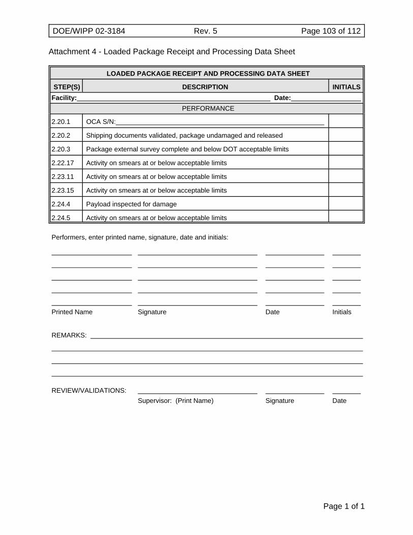
DOE/WIPP 02-3184 Rev. 5 Page 103 of 112
Page 1 of 1
Attachment 4 - Loaded Package Receipt and Processing Data Sheet
LOADED PACKAGE RECEIPT AND PROCESSING DATA SHEET
STEP(S) DESCRIPTION INITIALSFacility: Date:
PERFORMANCE
2.20.1 OCA S/N:
2.20.2 Shipping documents validated, package undamaged and released
2.20.3 Package external survey complete and below DOT acceptable limits
2.22.17 Activity on smears at or below acceptable limits
2.23.11 Activity on smears at or below acceptable limits
2.23.15 Activity on smears at or below acceptable limits
2.24.4 Payload inspected for damage
2.24.5 Activity on smears at or below acceptable limits
Performers, enter printed name, signature, date and initials:
Printed Name Signature Date Initials
REMARKS:
REVIEW/VALIDATIONS:Supervisor: (Print Name) Signature Date
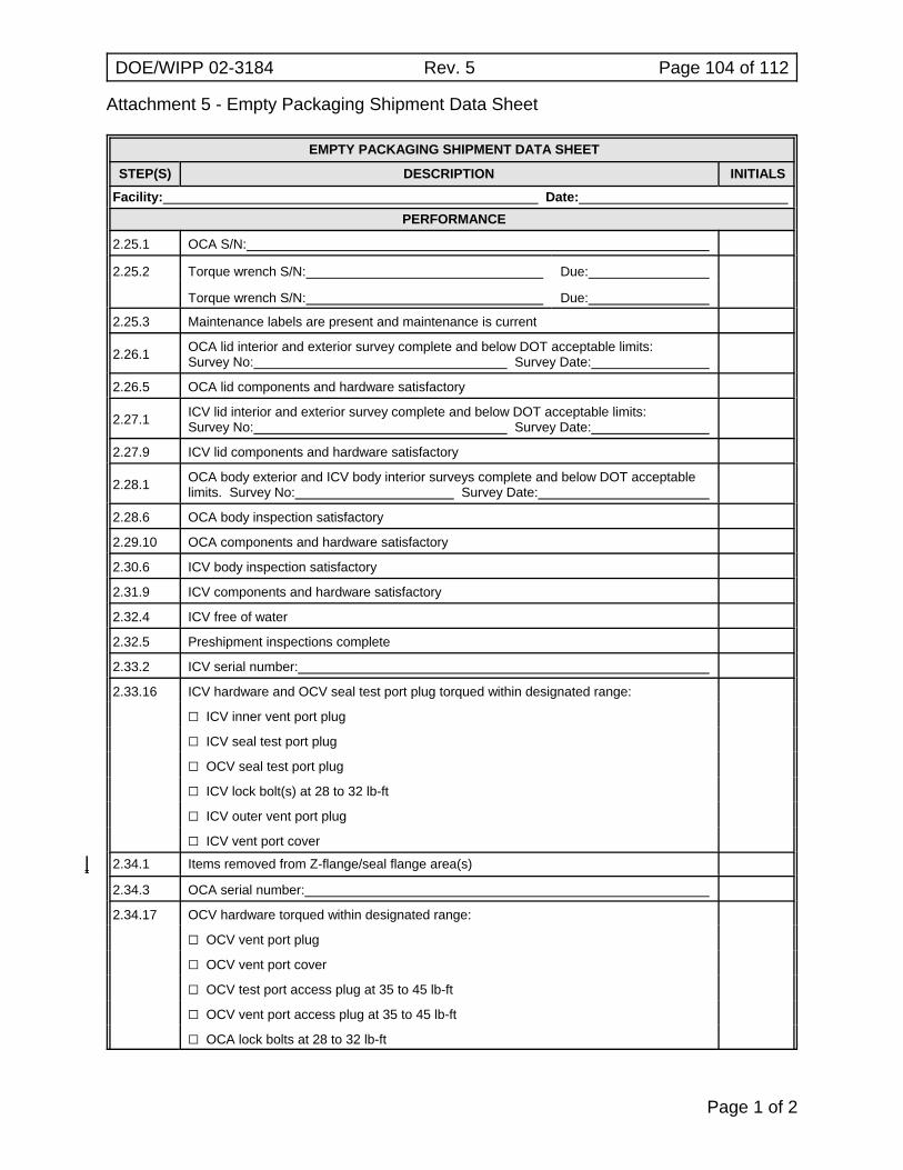
Attachment 5 - Empty Packaging Shipment Data Sheet
DOE/WIPP 02-3184 Rev. 5 Page 104 of 112
Page 1 of 2
EMPTY PACKAGING SHIPMENT DATA SHEET
STEP(S) DESCRIPTION INITIALS
Facility: Date:
PERFORMANCE
2.25.1 OCA S/N:
2.25.2 Torque wrench S/N: Due:
Torque wrench S/N: Due:
2.25.3 Maintenance labels are present and maintenance is current
2.26.1 OCA lid interior and exterior survey complete and below DOT acceptable limits:Survey No: Survey Date:
2.26.5 OCA lid components and hardware satisfactory
2.27.1 ICV lid interior and exterior survey complete and below DOT acceptable limits:Survey No: Survey Date:
2.27.9 ICV lid components and hardware satisfactory
2.28.1 OCA body exterior and ICV body interior surveys complete and below DOT acceptablelimits. Survey No: Survey Date:
2.28.6 OCA body inspection satisfactory
2.29.10 OCA components and hardware satisfactory
2.30.6 ICV body inspection satisfactory
2.31.9 ICV components and hardware satisfactory
2.32.4 ICV free of water
2.32.5 Preshipment inspections complete
2.33.2 ICV serial number:
2.33.16 ICV hardware and OCV seal test port plug torqued within designated range:
G ICV inner vent port plug
G ICV seal test port plug
G OCV seal test port plug
G ICV lock bolt(s) at 28 to 32 lb-ft
G ICV outer vent port plug
G ICV vent port cover
2.34.1| Items removed from Z-flange/seal flange area(s)||2.34.3 OCA serial number:
2.34.17 OCV hardware torqued within designated range:
G OCV vent port plug
G OCV vent port cover
G OCV test port access plug at 35 to 45 lb-ft
G OCV vent port access plug at 35 to 45 lb-ft
G OCA lock bolts at 28 to 32 lb-ft
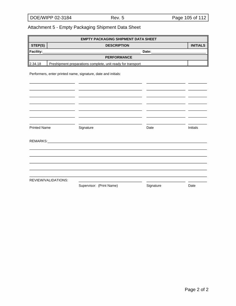
Attachment 5 - Empty Packaging Shipment Data Sheet
DOE/WIPP 02-3184 Rev. 5 Page 105 of 112
EMPTY PACKAGING SHIPMENT DATA SHEET
STEP(S) DESCRIPTION INITIALS
Facility: Date:
PERFORMANCE
Page 2 of 2
2.34.18 Preshipment preparations complete, unit ready for transport
Performers, enter printed name, signature, date and initials:
Printed Name Signature Date Initials
REMARKS:
REVIEW/VALIDATIONS:
Supervisor: (Print Name) Signature Date
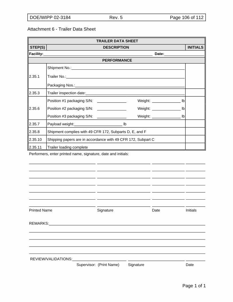
DOE/WIPP 02-3184 Rev. 5 Page 106 of 112
Page 1 of 1
Attachment 6 - Trailer Data Sheet
TRAILER DATA SHEETSTEP(S) DESCRIPTION INITIALSFacility: Date:
PERFORMANCE
2.35.1
Shipment No.:
Trailer No.:
Packaging Nos.:
2.35.3 Trailer inspection date:
2.35.6
Position #1 packaging S/N: Weight: lb
Position #2 packaging S/N: Weight: lb
Position #3 packaging S/N: Weight: lb
2.35.7 Payload weight: lb
2.35.8 Shipment complies with 49 CFR 172, Subparts D, E, and F
2.35.10 Shipping papers are in accordance with 49 CFR 172, Subpart C
2.35.11 Trailer loading complete
Performers, enter printed name, signature, date and initials:
Printed Name Signature Date Initials
REMARKS:
REVIEW/VALIDATIONS:Supervisor: (Print Name) Signature Date
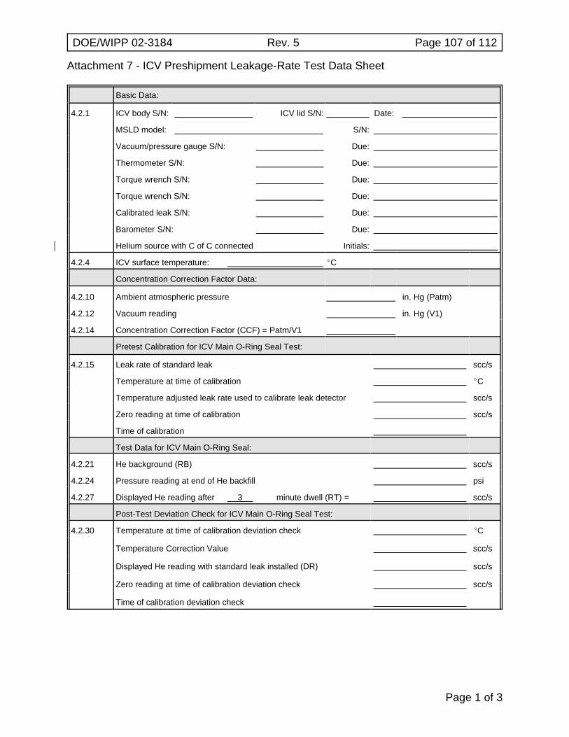
Attachment 7 - ICV Preshipment Leakage-Rate Test Data Sheet
DOE/WIPP 02-3184 Rev. 5 Page 107 of 112
Page 1 of 3
Basic Data:
4.2.1 ICV body S/N: ICV lid S/N: Date:
MSLD model: S/N:
Vacuum/pressure gauge S/N: Due:
Thermometer S/N: Due:
Torque wrench S/N: Due:
Torque wrench S/N: Due:
Calibrated leak S/N: Due:
Barometer S/N: Due:
Helium source with C of C connected| Initials:
4.2.4 ICV surface temperature: EC
Concentration Correction Factor Data:
4.2.10 Ambient atmospheric pressure in. Hg (Patm)
4.2.12 Vacuum reading in. Hg (V1)
4.2.14 Concentration Correction Factor (CCF) = Patm/V1
Pretest Calibration for ICV Main O-Ring Seal Test:
4.2.15 Leak rate of standard leak scc/s
Temperature at time of calibration EC
Temperature adjusted leak rate used to calibrate leak detector scc/s
Zero reading at time of calibration scc/s
Time of calibration
Test Data for ICV Main O-Ring Seal:
4.2.21 He background (RB) scc/s
4.2.24 Pressure reading at end of He backfill psi
4.2.27 Displayed He reading after 3 minute dwell (RT) = scc/s
Post-Test Deviation Check for ICV Main O-Ring Seal Test:
4.2.30 Temperature at time of calibration deviation check EC
Temperature Correction Value scc/s
Displayed He reading with standard leak installed (DR) scc/s
Zero reading at time of calibration deviation check scc/s
Time of calibration deviation check
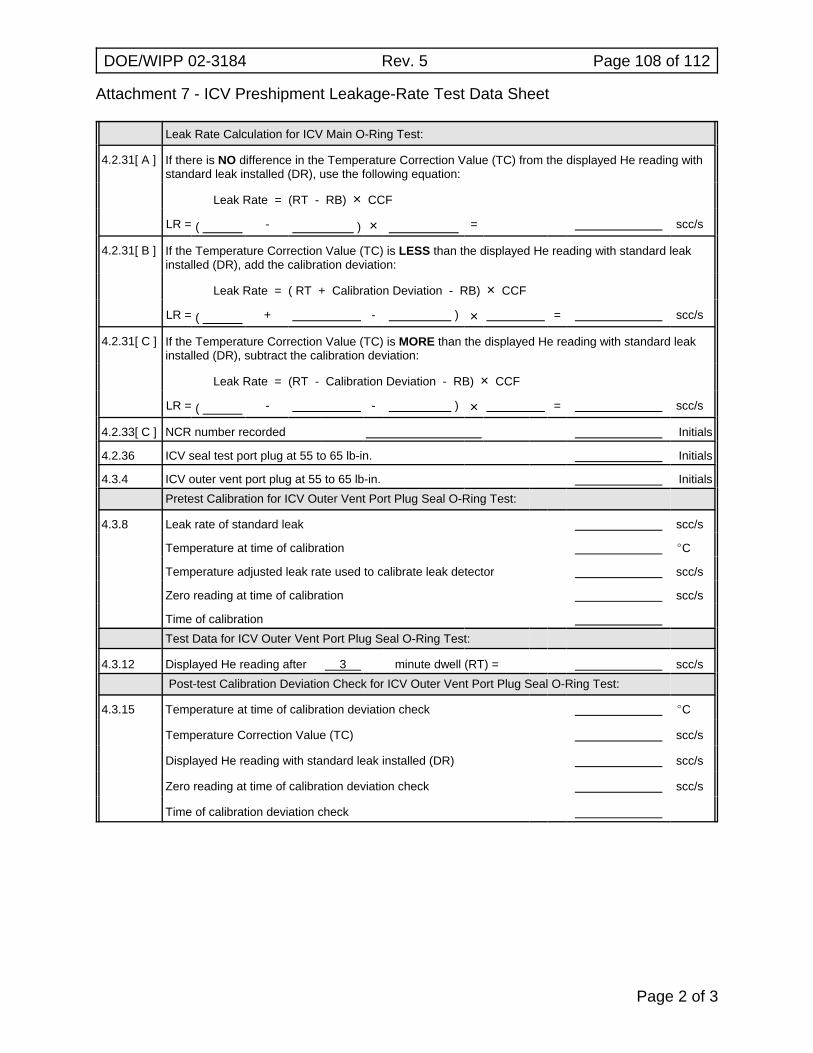
Attachment 7 - ICV Preshipment Leakage-Rate Test Data Sheet
DOE/WIPP 02-3184 Rev. 5 Page 108 of 112
Page 2 of 3
Leak Rate Calculation for ICV Main O-Ring Test:
4.2.31[ A ] If there is NO difference in the Temperature Correction Value (TC) from the displayed He reading withstandard leak installed (DR), use the following equation:
Leak Rate = (RT - RB) × CCF
LR = ( - ) × = scc/s
4.2.31[ B ] If the Temperature Correction Value (TC) is LESS than the displayed He reading with standard leakinstalled (DR), add the calibration deviation:
Leak Rate = ( RT + Calibration Deviation - RB) × CCF
LR = ( + - ) × = scc/s
4.2.31[ C ] If the Temperature Correction Value (TC) is MORE than the displayed He reading with standard leakinstalled (DR), subtract the calibration deviation:
Leak Rate = (RT - Calibration Deviation - RB) × CCF
LR = ( - - ) × = scc/s
4.2.33[ C ] NCR number recorded Initials
4.2.36 ICV seal test port plug at 55 to 65 lb-in. Initials
4.3.4 ICV outer vent port plug at 55 to 65 lb-in. InitialsPretest Calibration for ICV Outer Vent Port Plug Seal O-Ring Test:
4.3.8 Leak rate of standard leak scc/s
Temperature at time of calibration EC
Temperature adjusted leak rate used to calibrate leak detector scc/s
Zero reading at time of calibration scc/s
Time of calibrationTest Data for ICV Outer Vent Port Plug Seal O-Ring Test:
4.3.12 Displayed He reading after 3 minute dwell (RT) = scc/s Post-test Calibration Deviation Check for ICV Outer Vent Port Plug Seal O-Ring Test:
4.3.15 Temperature at time of calibration deviation check EC
Temperature Correction Value (TC) scc/s
Displayed He reading with standard leak installed (DR) scc/s
Zero reading at time of calibration deviation check scc/s
Time of calibration deviation check
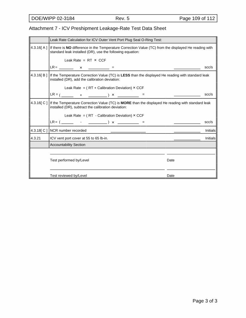
Attachment 7 - ICV Preshipment Leakage-Rate Test Data Sheet
DOE/WIPP 02-3184 Rev. 5 Page 109 of 112
Page 3 of 3
Leak Rate Calculation for ICV Outer Vent Port Plug Seal O-Ring Test:
4.3.16[ A ] If there is NO difference in the Temperature Correction Value (TC) from the displayed He reading withstandard leak installed (DR), use the following equation:
Leak Rate = RT × CCF
LR = × = scc/s
4.3.16[ B ] If the Temperature Correction Value (TC) is LESS than the displayed He reading with standard leakinstalled (DR), add the calibration deviation:
Leak Rate = ( RT + Calibration Deviation) × CCF
LR = ( + ) × = scc/s
4.3.16[ C ] If the Temperature Correction Value (TC) is MORE than the displayed He reading with standard leakinstalled (DR), subtract the calibration deviation:
Leak Rate = ( RT - Calibration Deviation) × CCF
LR = ( - ) × = scc/s
4.3.18[ C ] NCR number recorded Initials
4.3.21 ICV vent port cover at 55 to 65 lb-in. Initials
Accountability Section
Test performed by/Level Date
Test reviewed by/Level Date
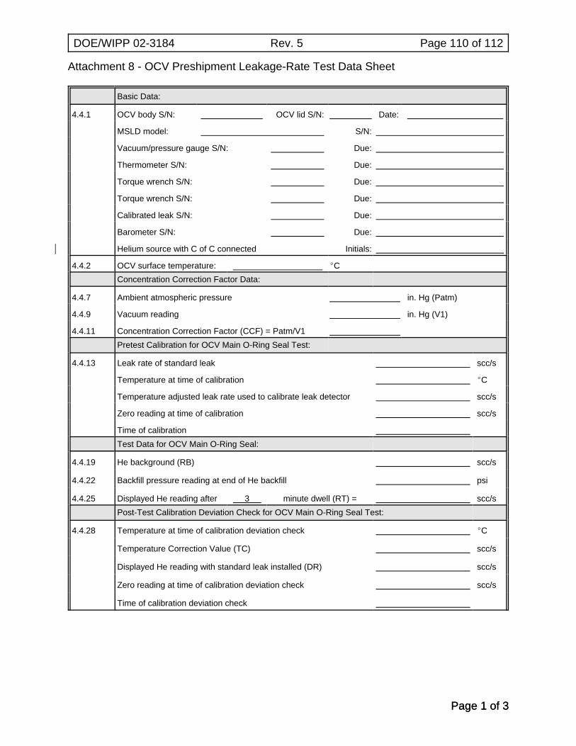
Attachment 8 - OCV Preshipment Leakage-Rate Test Data Sheet
DOE/WIPP 02-3184 Rev. 5 Page 110 of 112
Page 1 of 3Page 1 of 3
Basic Data:
4.4.1 OCV body S/N: OCV lid S/N: Date:
MSLD model: S/N:
Vacuum/pressure gauge S/N: Due:
Thermometer S/N: Due:
Torque wrench S/N: Due:
Torque wrench S/N: Due:
Calibrated leak S/N: Due:
Barometer S/N: Due:
Helium source with C of C connected| Initials:
4.4.2 OCV surface temperature: ECConcentration Correction Factor Data:
4.4.7 Ambient atmospheric pressure in. Hg (Patm)
4.4.9 Vacuum reading in. Hg (V1)
4.4.11 Concentration Correction Factor (CCF) = Patm/V1Pretest Calibration for OCV Main O-Ring Seal Test:
4.4.13 Leak rate of standard leak scc/s
Temperature at time of calibration EC
Temperature adjusted leak rate used to calibrate leak detector scc/s
Zero reading at time of calibration scc/s
Time of calibrationTest Data for OCV Main O-Ring Seal:
4.4.19 He background (RB) scc/s
4.4.22 Backfill pressure reading at end of He backfill psi
4.4.25 Displayed He reading after 3 minute dwell (RT) = scc/sPost-Test Calibration Deviation Check for OCV Main O-Ring Seal Test:
4.4.28 Temperature at time of calibration deviation check EC
Temperature Correction Value (TC) scc/s
Displayed He reading with standard leak installed (DR) scc/s
Zero reading at time of calibration deviation check scc/s
Time of calibration deviation check
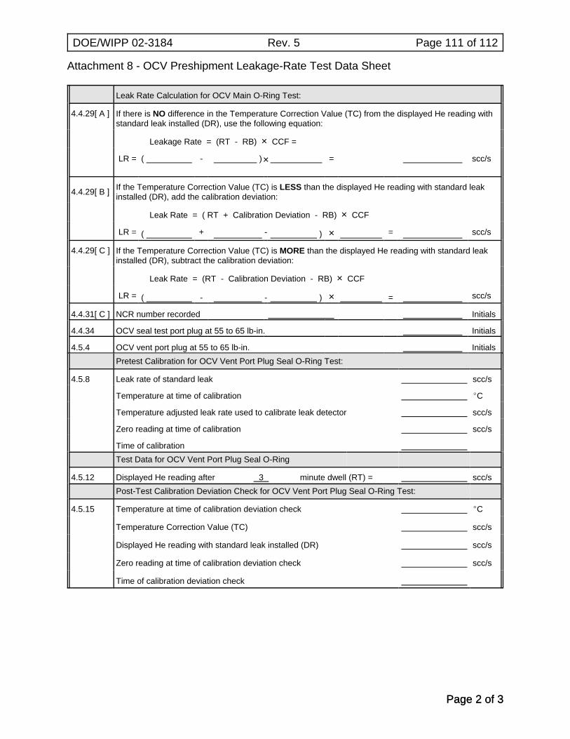
Attachment 8 - OCV Preshipment Leakage-Rate Test Data Sheet
DOE/WIPP 02-3184 Rev. 5 Page 111 of 112
Page 2 of 3Page 2 of 3
Leak Rate Calculation for OCV Main O-Ring Test:
4.4.29[ A ] If there is NO difference in the Temperature Correction Value (TC) from the displayed He reading withstandard leak installed (DR), use the following equation:
Leakage Rate = (RT - RB) × CCF =
LR = ( - )× = scc/s
4.4.29[ B ] If the Temperature Correction Value (TC) is LESS than the displayed He reading with standard leakinstalled (DR), add the calibration deviation:
Leak Rate = ( RT + Calibration Deviation - RB) × CCF
LR = ( + - ) × = scc/s
4.4.29[ C ] If the Temperature Correction Value (TC) is MORE than the displayed He reading with standard leakinstalled (DR), subtract the calibration deviation:
Leak Rate = (RT - Calibration Deviation - RB) × CCF
LR = ( - - ) × = scc/s
4.4.31[ C ] NCR number recorded Initials
4.4.34 OCV seal test port plug at 55 to 65 lb-in. Initials
4.5.4 OCV vent port plug at 55 to 65 lb-in. InitialsPretest Calibration for OCV Vent Port Plug Seal O-Ring Test:
4.5.8 Leak rate of standard leak scc/s
Temperature at time of calibration EC
Temperature adjusted leak rate used to calibrate leak detector scc/s
Zero reading at time of calibration scc/s
Time of calibrationTest Data for OCV Vent Port Plug Seal O-Ring
4.5.12 Displayed He reading after 3 minute dwell (RT) = scc/sPost-Test Calibration Deviation Check for OCV Vent Port Plug Seal O-Ring Test:
4.5.15 Temperature at time of calibration deviation check EC
Temperature Correction Value (TC) scc/s
Displayed He reading with standard leak installed (DR) scc/s
Zero reading at time of calibration deviation check scc/s
Time of calibration deviation check
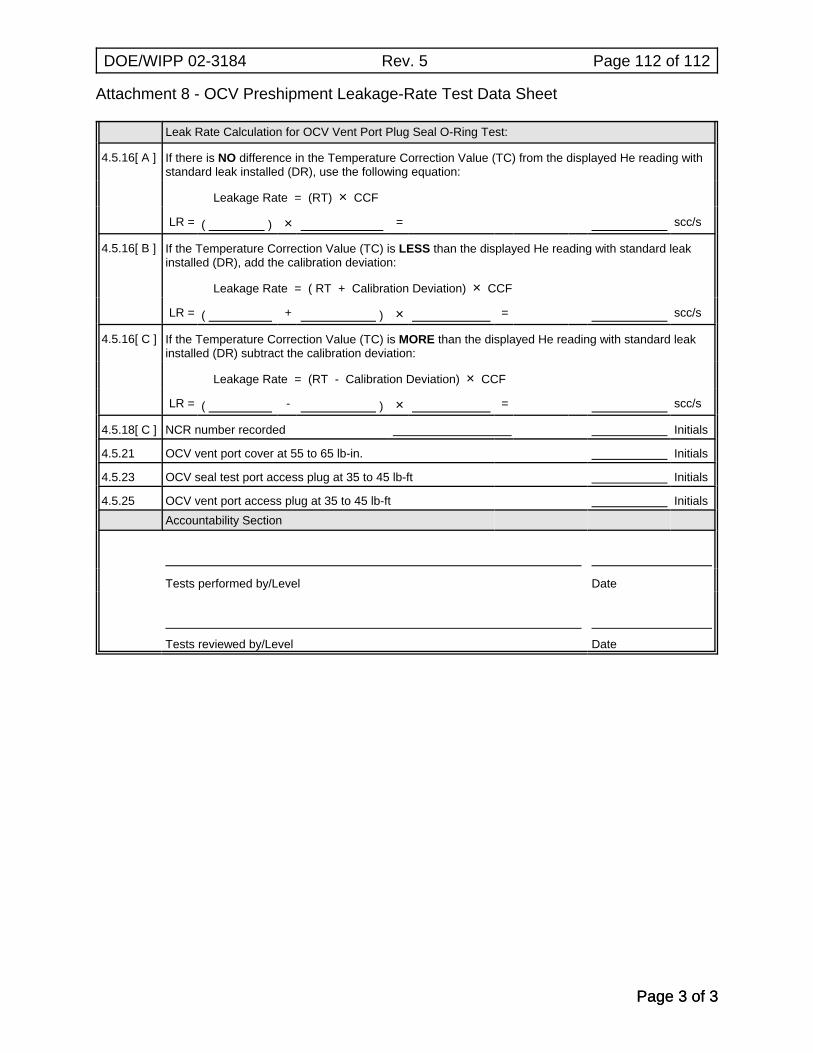
Attachment 8 - OCV Preshipment Leakage-Rate Test Data Sheet
DOE/WIPP 02-3184 Rev. 5 Page 112 of 112
Page 3 of 3Page 3 of 3
Leak Rate Calculation for OCV Vent Port Plug Seal O-Ring Test:
4.5.16[ A ] If there is NO difference in the Temperature Correction Value (TC) from the displayed He reading withstandard leak installed (DR), use the following equation:
Leakage Rate = (RT) × CCF
LR = ( ) × = scc/s
4.5.16[ B ] If the Temperature Correction Value (TC) is LESS than the displayed He reading with standard leakinstalled (DR), add the calibration deviation:
Leakage Rate = ( RT + Calibration Deviation) × CCF
LR = ( + ) × = scc/s
4.5.16[ C ] If the Temperature Correction Value (TC) is MORE than the displayed He reading with standard leakinstalled (DR) subtract the calibration deviation:
Leakage Rate = (RT - Calibration Deviation) × CCF
LR = ( - ) × = scc/s
4.5.18[ C ] NCR number recorded Initials
4.5.21 OCV vent port cover at 55 to 65 lb-in. Initials
4.5.23 OCV seal test port access plug at 35 to 45 lb-ft Initials
4.5.25 OCV vent port access plug at 35 to 45 lb-ft InitialsAccountability Section
Tests performed by/Level Date
Tests reviewed by/Level Date