Embed Size (px)
Citation preview

D202472-16
You can also download the latest manual from our website.
MIMAKI ENGINEERING CO., LTD.URL: http://eng.mimaki.co.jp/
i
CAUTION ......................................................................... vCAUTION ........................................................................ vRequests ......................................................................... vFCC Statement (USA) ..................................................... vInterference to televisions and radios .............................. v
Foreword ......................................................................... viAbout media ....................................................................viOn This Operation manual ..............................................vi
Features ..........................................................................viiSafety Precautions .........................................................viii
Pictorial signs ................................................................ viiiSafety Labels ................................................................... x
How to Read This Operation Manual .............................. xi
CHAPTER 1 Before Use
Where to install this machine .................................. 1-2Configuration and function ...................................... 1-3
The Front ...................................................................1-3The Rear ...................................................................1-4Operation Panel ........................................................1-5Tray ...........................................................................1-6Carriage ....................................................................1-6Pinch rollers and grit rollers .......................................1-7Clamp ........................................................................1-8Sheet sensor .............................................................1-8
Connecting the cables ............................................ 1-9USB Cable Connection .............................................1-9RS-232C Cable Connection ......................................1-9LAN Cable connection ..............................................1-9Connecting the power cable ....................................1-10
Menu mode .......................................................... 1-11
CHAPTER 2 Basic Operations
Installing a tool ....................................................... 2-3Using a cutter ............................................................2-3How to Install a Ballpoint Pen ...................................2-6
Turning the power on .............................................. 2-8Setting the tool conditions ...................................... 2-9
Kinds of the Tool Conditions .....................................2-9Select the tool condition ..........................................2-10Set the Tool Conditions ...........................................2-10
TABLE OF CONTENS
ii
Setting a sheet ..................................................... 2-13Setting a leaf sheet (cut sheet) ............................... 2-16How to Place the Roll Sheet (CG-60SRIII) ............. 2-17How to Place the Roll Sheet (CG-100SRIII/CG-130SRIII) ................................... 2-19
Test cutting (plotting) ........................................... 2-22Cutting (plotting) ................................................... 2-23
Setting the origin ..................................................... 2-23Start cutting (plotting) ............................................. 2-24Cut off the Sheet (Manual Cutting) ......................... 2-25
Turning the power off ........................................... 2-26
CHAPTER 3 Useful Function
Functions in the Jog Mode ..................................... 3-2Setting the origin ....................................................... 3-2Two-point axis alignment .......................................... 3-3Cutting area .............................................................. 3-4Digitization operation ................................................ 3-5
Set the distance compensation .............................. 3-6Perform Multiple Cuttings ....................................... 3-9Cut Out Data with Registration Mark ................... 3-11
The Flow of Cutting out the Registered Data ......... 3-11Enter the registration mark detection mode ............ 3-11Precautions in inputting data with registration marks . 3-12Set for Detecting the Registration Marks ................ 3-16Method of detecting registration marks .................. 3-21Confirm the following when failed in cutting correctly. 3-29
Expand the cutting (plotting) area ........................ 3-35Set the EXPANDS function to ON. ......................... 3-35
Switch the cutting (plotting) direction ................... 3-37The Setting of ROTATION. ..................................... 3-37
Perform DIVISION cut .......................................... 3-39Set the Y direction (width direction) DIVISION cut . 3-39Set the X direction (feeding direction) DIVISION cut .. 3-41Cut Data via DIVISION CUT. .................................. 3-43
Change the cutting (plotting) order ...................... 3-44Set SORTING . ....................................................... 3-44Sorting sequence .................................................... 3-46

iii
Other Useful Functions ......................................... 3-47Feed the paper ........................................................3-47HOLD ......................................................................3-48DATA CLEAR - Discontinue Plotting - ..................3-48Perform SAMPLE CUT to Find out the Cause of Cutting Error. .......................................................................3-49Output the Setting List .............................................3-50Output the received data by the ASCII code [ASCII DUMP] .....................................................................3-51Set the configurations with a computer ...................3-52Make the media without uncut area ........................3-54Select the number of pinch roller to use ..................3-56Setting the FEED OFFSET .....................................3-57Setting the FEED SPEED .......................................3-58Setting the PRE FEED ............................................3-59Set the network .......................................................3-61Setting event mail function ......................................3-63
Miscellaneous Settings ......................................... 3-74Switch the display language ....................................3-74Switch the User .......................................................3-75Other Convenient Settings ......................................3-76Copy the set value from the other user setting. ......3-84Reset the setting values to the initial state. .............3-85
CHAPTER 4 In Case of Trouble
Before taking a phenomenon as a trouble .............. 4-2Troubles for which error messages are given on the LCD ........................................................................ 4-4
Error message ...........................................................4-4Status message ........................................................4-7
CHAPTER 5 Appendix
Specifications of the main unit ................................ 5-2Repeatability condition ..............................................5-3
Cutter blade ............................................................ 5-4Replacing the cutter ..................................................5-4Adjusting the cutter blade ..........................................5-4Replacing the cutter other than supplied one ............5-5Adjusting blade edge of cutter other than supplied one 5-5
Note slip ................................................................. 5-6

iv
Function Flowchart ................................................. 5-7Functions invoked with the specific keys .................. 5-7Functions invoked with the jog mode (jog keys) ....... 5-9Functions ................................................................ 5-10

v
CAUTIONCAUTION
DISCLAIMER OF WARRANTY : THIS LIMITED WARRANTY OF MIMAKI SHALL BE THE SOLE ANDEXCLUSIVE WARRANTY AND IS IN LIEU OF ALL OTHER WARRANTIES,EXPRESS OR IMPLIED,INCLUDING, BUT NOT LIMITED TO, ANY IMPLIED WARRANTY OF MERCHANTABILITY OR FITNESS,AND MIMAKI NEITHER ASSUMES NOR AUTHORIZES DEALER TO ASSUME FOR IT ANY OTHEROBLIGATION OR LIABILITY OR MAKE ANY OTHER WARRANTY OR MAKE ANY OTHER WARRANTY INCONNECTION WITH ANY PRODUCT WITHOUT MIMAKI’S PRIOR WRITTEN CONSENT. IN NO EVENTSHALL MIMAKI BE LIABLE FOR SPECIAL, INCIDENTAL OR CONSEQUENTIAL DAMAGES OR FOR LOSSOF PROFITS OF DEALER OR CUSTOMERS OF ANY PRODUCT.
Requests
• This Operation manual has been carefully prepared for your easy understanding.However, please do nothesitate to contact a distributor in your district or our office if you have any inquiry.
• Description contained in this Operation manual are subject to change without notice for improvement.• Generally, names and designations referred to in this Operation manual are trade marks or registered trade
marks of the manufacturers or suppliers.
FCC Statement (USA)
This equipment has been tested and found to comply with the limits for a Class A digital device, pursuant toPart 15 of the FCC Rules. These limits are designed to provide reasonable protection against harmfulinterference when the equipment is operated in a commercial environment. This equipment generates, usesand can radiate radio frequency energy and, if not installed and used in accordance with the Operation manual,may cause harmful interference to radio communications. Operation of this equipment in a residential area islikely to cause harmful interference in which cause the user will be required to correct the interference at hisown expense.
Interference to televisions and radios
The product described in this manual generates high frequency when operating.The product can interfere with radios and televisions if set up or commissioned under improper conditions. Theproduct is not guaranteed against any damage to specific-purpose radio and televisions.The product’s interference with your radio or television will be checked by turning on/off the power switch of theproduct.In the event that the product is the cause of interference, try to eliminate it by taking one of the followingcorrective measures or taking some of them in combination.
• Change the orientation of the antenna of the television set or radio to find a position without reception difficulty.• Separate the television set or radio from this product.• Plug the power cord of this product into an outlet which is isolated from power circuits connected to the
television set or radio.
• In the case where MIMAKI-recommended cable is not used for connection of this device, limits provided by FCC rules can be exceeded.To prevent this, use of MIMAKI-recommended cable is essential for the connection of this plotter.

vi
1
2
3
4
5
6
ForewordAbout media
Please follow the local regulations to dispose of roll sheets or other media.Congratulations on your purchase of a CG-SRII series cutting plottver.CG-SRII series cutting plotter is a highly functional cutting plotter with the high-speed registration markdetection.Read this Operation manual carefully and make the most effective use of your plotter.
On This Operation manual
• This Operation manual describes the operation and maintenance of CG-SRII series cutting plotter (hereinafterreferred to as the plotter).
• Please read and fully understand this Operation manual before putting the machine into service. It is alsonecessary to keep this peration manual on hand.
• Make arrangements to deliver this Operation manual to the person in charge of the operation of this plotter.• This Operation manual has been carefully prepared for your easy understanding. However, please do not
hesitate to contact a distributor in your district or our office if you have any inquiry.• Description contained in this Operation manual are subject to change without notice for improvement.• In the case where this Operation manual should be illegible due to destruction or lost by fire or breakage,
purchase another copy of the Operation manual from our office.• You can also download the latest operation manual from our website.
Reproduction of this manual is strictly prohibited.All Rights Reserved. Copyright © 2014 MIMAKI ENGINEERING Co., Ltd.

vii
FeaturesThe features of the plotter are described below. Together with the method of operation of the plotter explainedin this manual, they help you understand how to use the machine properly.
Mark Sensor
The high accuracy mark-detection sensor enables the plotter to read the mark plotted on sheets automatically,compensate distances, set the plotting origin and correct paper skew.
Roll Sheet Stopper
The roll sheet stopper helps the plotter feed a roll paper without sagging. In addition, the improved sheet let-offsurface reduces the jam of a roll sheet. Thus the troubles are minimized.
Two Clamp Pressure Modes Changeover Mechanism
The sheet clamp system incorporate two clamp pressure modes changeover mechanism to widen the availablesheet size range.Strong pressure mode substantially increases the clamp pressure to prevent a long sheet from slipping.The moderate pressure mode prevents the media from getting scratched by the grit roller during plot operation.
Front Loading
You can mount the roll-placing table in the front side to cut the front-loaded roll sheet.
Plug-in Cutting Software (FineCut) Attached
The plug-in software FineCut, enables easy and fine cutting of the characters or illustrations edited on theIllustrator or CorelDRAW.
viii
1
2
3
4
5
6
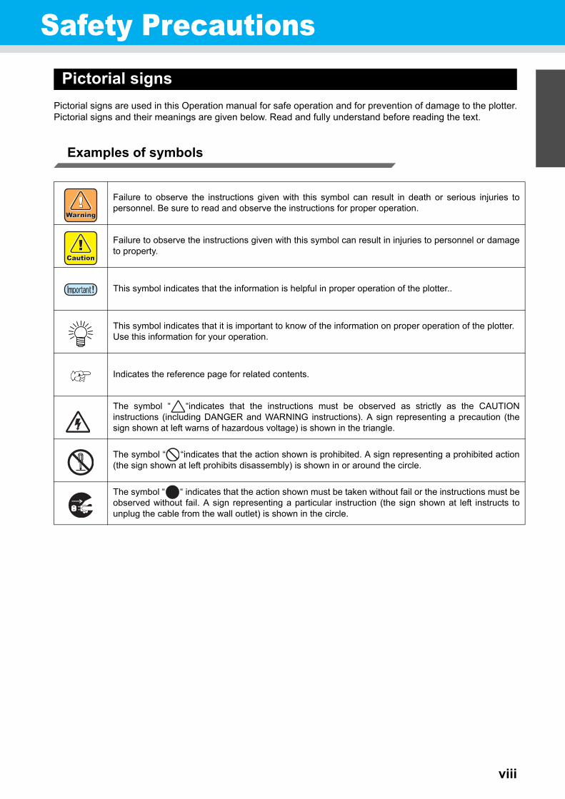
Safety PrecautionsPictorial signs
Pictorial signs are used in this Operation manual for safe operation and for prevention of damage to the plotter.Pictorial signs and their meanings are given below. Read and fully understand before reading the text.
Examples of symbols
Failure to observe the instructions given with this symbol can result in death or serious injuries topersonnel. Be sure to read and observe the instructions for proper operation.
Failure to observe the instructions given with this symbol can result in injuries to personnel or damageto property.
This symbol indicates that the information is helpful in proper operation of the plotter..
This symbol indicates that it is important to know of the information on proper operation of the plotter.Use this information for your operation.
Indicates the reference page for related contents.
The symbol “ “indicates that the instructions must be observed as strictly as the CAUTIONinstructions (including DANGER and WARNING instructions). A sign representing a precaution (thesign shown at left warns of hazardous voltage) is shown in the triangle.
The symbol “ “indicates that the action shown is prohibited. A sign representing a prohibited action(the sign shown at left prohibits disassembly) is shown in or around the circle.
The symbol “ “ indicates that the action shown must be taken without fail or the instructions must beobserved without fail. A sign representing a particular instruction (the sign shown at left instructs tounplug the cable from the wall outlet) is shown in the circle.
ix
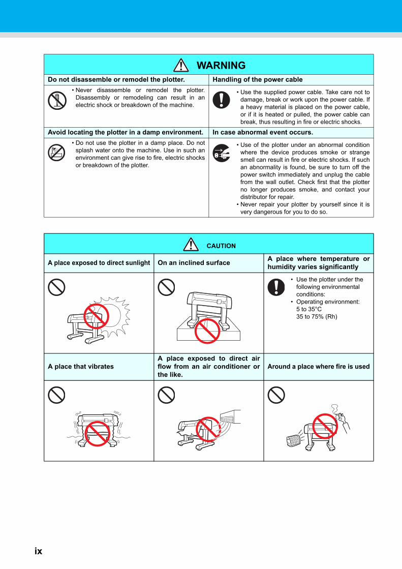
WARNINGDo not disassemble or remodel the plotter. Handling of the power cable
• Never disassemble or remodel the plotter.Disassembly or remodeling can result in anelectric shock or breakdown of the machine.
• Use the supplied power cable. Take care not todamage, break or work upon the power cable. Ifa heavy material is placed on the power cable,or if it is heated or pulled, the power cable canbreak, thus resulting in fire or electric shocks.
Avoid locating the plotter in a damp environment. In case abnormal event occurs.
• Do not use the plotter in a damp place. Do notsplash water onto the machine. Use in such anenvironment can give rise to fire, electric shocksor breakdown of the plotter.
• Use of the plotter under an abnormal conditionwhere the device produces smoke or strangesmell can result in fire or electric shocks. If suchan abnormality is found, be sure to turn off thepower switch immediately and unplug the cablefrom the wall outlet. Check first that the plotterno longer produces smoke, and contact yourdistributor for repair.
• Never repair your plotter by yourself since it isvery dangerous for you to do so.
CAUTION
A place exposed to direct sunlight On an inclined surfaceA place where temperature orhumidity varies significantly
• Use the plotter under the following environmental conditions:
• Operating environment:5 to 35°C35 to 75% (Rh)
A place that vibratesA place exposed to direct airflow from an air conditioner orthe like.
Around a place where fire is used
Safety Precautions
x
1
2
3
4
5
6
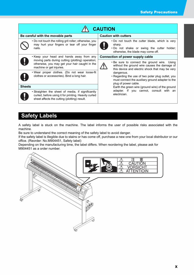
Safety Labels
A safety label is stuck on the machine. The label informs the user of possible risks associated with themachine.Be sure to understand the correct meaning of the safety label to avoid danger. If the safety label is illegible due to stains or has come off, purchase a new one from your local distributor or ouroffice. (Reorder: No.M904451, Safety label)Depending on the manufacturing time, the label differs. When reordering the label, please ask forM904451 as a order number.
CAUTIONBe careful with the movable parts Caution with cutters
• Do not touch the rolling grit roller; otherwise, youmay hurt your fingers or tear off your fingernails.
• Do not touch the cutter blade, which is verysharp.
• Do not shake or swing the cutter holder;otherwise, the blade may come off.
• Keep your head and hands away from anymoving parts during cutting (plotting) operation;otherwise, you may get your hair caught in themachine or get injuries.
Connection of power supply cable
• Be sure to connect the ground wire. Usingwithout the ground wire causes the damage ofthis device and electric shock that may be verydangerous.
• Regarding the use of two polar plug outlet, youmust connect the auxiliary ground adapter to theplug of power cable.Earth the green wire (ground wire) of the groundadapter. If you cannot, consult with anelectrician.
• Wear proper clothes. (Do not wear loose-fitclothes or accessories). Bind a long hair.
Sheets
• Straighten the sheet of media, if significantlycurled, before using it for printing. Heavily curledsheet affects the cutting (plotting) result.
xi
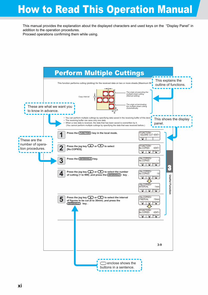
How to Read This Operation ManualThis manual provides the explanation about the displayed characters and used keys on the “Display Panel” inaddition to the operation procedures.Proceed operations confirming them while using.
3-9
33
Useful Function
Perform Multiple CuttingsThis function performs cutting (plotting) for the received data on two or more sheets.(Maximum 999 cuttings)
• You can perform multiple cuttings by specifying data saved in the receiving buffer of this device.• The receiving buffer can save only one data.• When a new data is received, the data that has been saved is overwritten by it.
(You cannot perform multiple cuttings by specifying the data that was received before.)
1 Press the key in the local mode.
2 Press the jog key or to select [No.COPIES].
3 Press the key.
4 Press the jog key or to select the number of cutting (1 to 999) ,and press the key .
5 Press the jog key or to select the interval of figures to be cut (0 to 30mm) ,and press the
key .
Copy interval
The origin at executing the multiple sheet cutting.(Manual setting)
The origin at terminating the multiple sheet cutting(Automatically
FUNCTION
ENTER/HOLD
ENTER/HOLD
ENTER/HOLD
<FUNCTION> SQUARE CUT <ENT>
F U N C
<FUNCTION>No.COPIES <ENT>
R E M O T ET O O LF U N C
<FUNCTION>No.COPIES <ENT>
R E M O T ET O O LF U N C
<No.COPIES>No.COPIES : 1
R E M O T ET O O LF U N C
<No.COPIES>No.COPIES :10
R E M O T ET O O LF U N C
<No.COPIES>INTERVAL :1mm
R E M O T ET O O LF U N C
<No.COPIES>ITNERVAL :10mm
R E M O T ET O O LF U N C
enclose shows the buttons in a sentence.
This shows the display panel.
These are what we want you to know in advance.
These are the number of opera-tion procedures.
This explains the outline of functions.
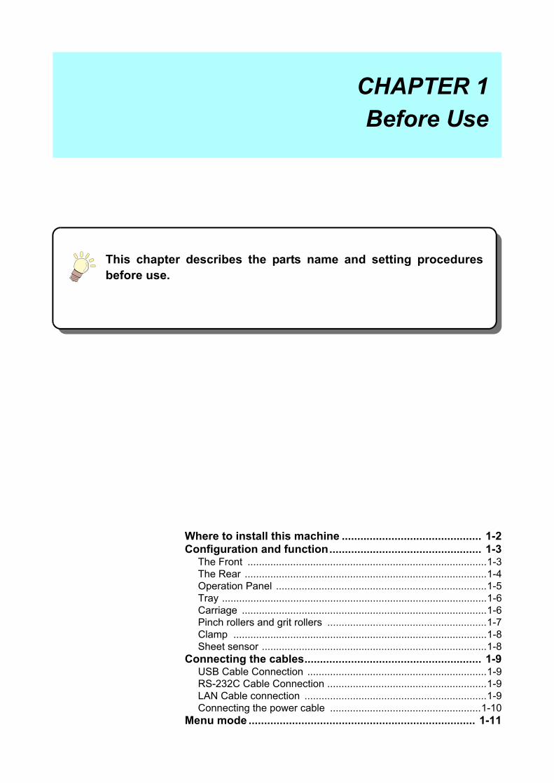
This chapter describes the parts name and setting proceduresbefore use.
Where to install this machine ............................................. 1-2Configuration and function................................................. 1-3
The Front ....................................................................................1-3The Rear .....................................................................................1-4Operation Panel ..........................................................................1-5Tray .............................................................................................1-6Carriage ......................................................................................1-6Pinch rollers and grit rollers ........................................................1-7Clamp .........................................................................................1-8Sheet sensor ...............................................................................1-8
Connecting the cables......................................................... 1-9USB Cable Connection ...............................................................1-9RS-232C Cable Connection ........................................................1-9LAN Cable connection ................................................................1-9Connecting the power cable .....................................................1-10
Menu mode ......................................................................... 1-11
CHAPTER 1
Before Use
1-2
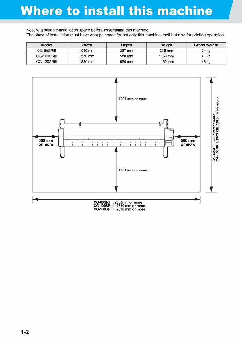
Where to install this machineSecure a suitable installation space before assembling this machine.The place of installation must have enough space for not only this machine itself but also for printing operation.
Model Width Depth Height Gross weight
CG-60SRIII 1030 mm 287 mm 335 mm 24 kg
CG-100SRIII 1530 mm 580 mm 1150 mm 41 kg
CG-130SRIII 1830 mm 580 mm 1150 mm 46 kg
CG-60SRIII : 2030mm or moreCG-100SRIII : 2530 mm or moreCG-130SRIII : 2830 mm or more
500 mmor more
500 mmor more
1000 mm or more
1000 mm or more
CG
-60
SR
III:
22
87
mm
or
mo
reC
G-1
00
SR
III/1
30S
RII
I: 2
580
mm
or
mo
re
1-3
1
Befo
re Use
3
4
5
6
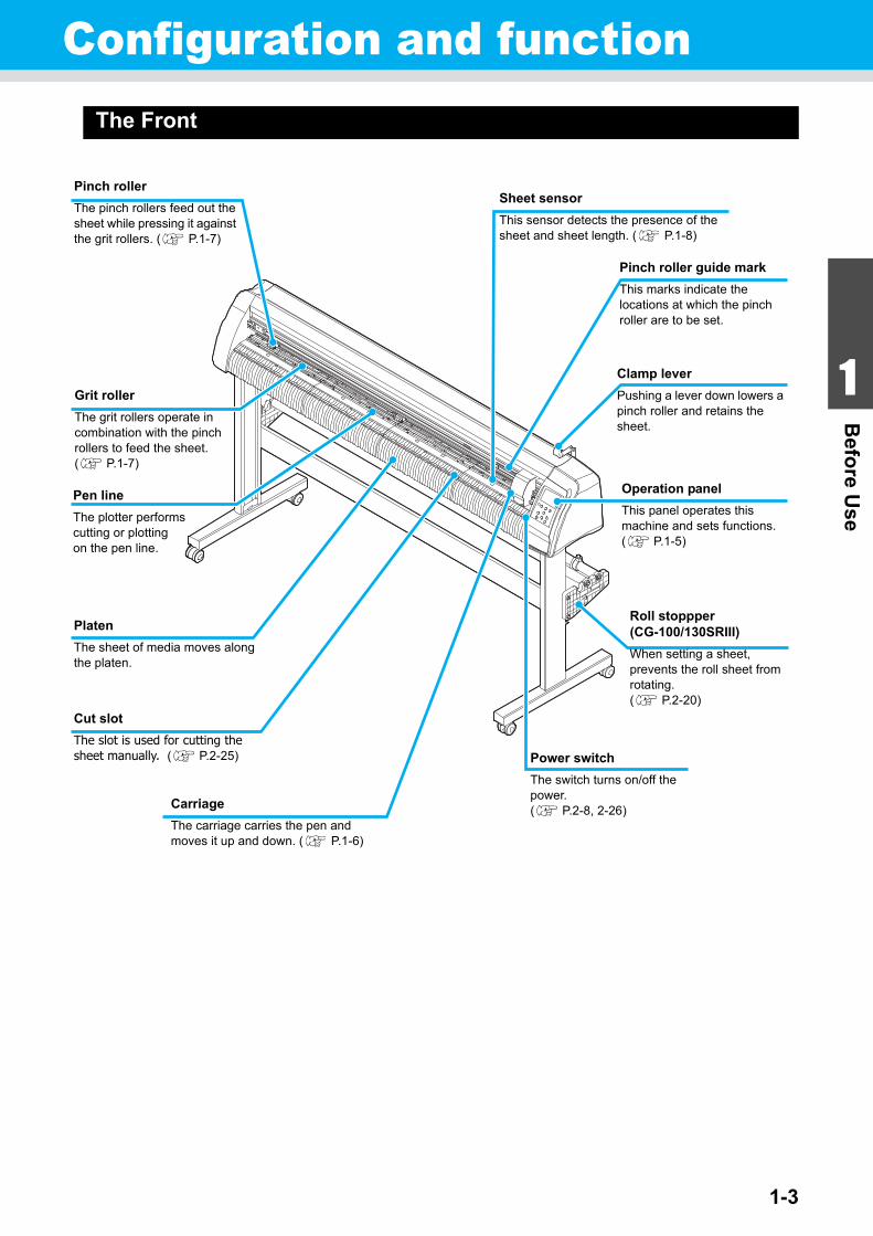
Configuration and functionThe Front
Carriage
The carriage carries the pen and moves it up and down. ( P.1-6)
Power switch
The switch turns on/off the power.( P.2-8, 2-26)
Grit roller
The grit rollers operate in combination with the pinch rollers to feed the sheet. ( P.1-7)
Platen
The sheet of media moves along the platen.
Operation panel
This panel operates this machine and sets functions. ( P.1-5)
Clamp lever
Pushing a lever down lowers a pinch roller and retains the sheet.
Pinch roller
The pinch rollers feed out the sheet while pressing it against the grit rollers. ( P.1-7)
Pen line
The plotter performs cutting or plotting on the pen line.
Pinch roller guide mark
This marks indicate the locations at which the pinch roller are to be set.
Roll stoppper(CG-100/130SRIII)
When setting a sheet, prevents the roll sheet from rotating. ( P.2-20)
Cut slot
The slot is used for cutting the sheet manually. ( P.2-25)
Sheet sensor
This sensor detects the presence of the sheet and sheet length. ( P.1-8)
1-4
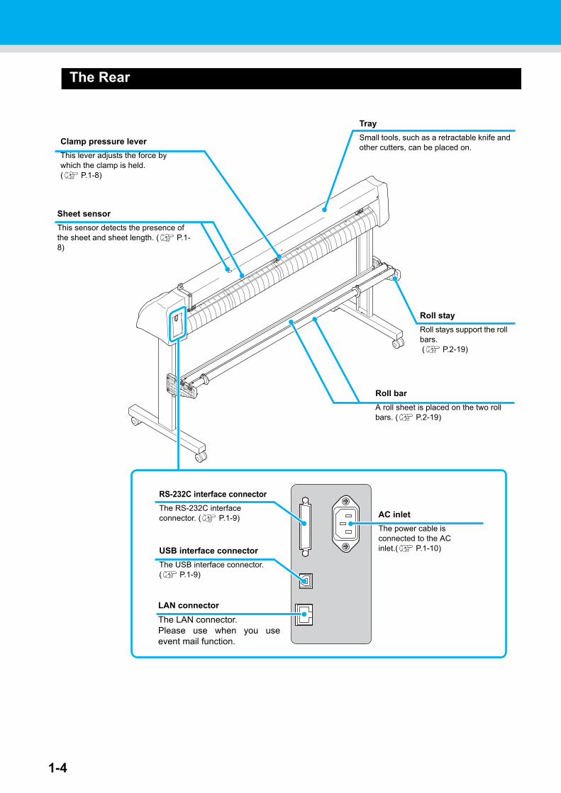
The Rear
Clamp pressure lever
This lever adjusts the force by which the clamp is held.( P.1-8)
Tray
Small tools, such as a retractable knife and other cutters, can be placed on.
Roll bar
A roll sheet is placed on the two roll bars. ( P.2-19)
AC inlet
The power cable is connected to the AC inlet.( P.1-10)
Sheet sensor
This sensor detects the presence of the sheet and sheet length. ( P.1-8)
Roll stay
Roll stays support the roll bars. ( P.2-19)
RS-232C interface connector
The RS-232C interface connector. ( P.1-9)
LAN connector
The LAN connector.Please use when you useevent mail function.
USB interface connector
The USB interface connector. ( P.1-9)
Configuration and function
1-5
1
Befo
re Use
3
4
5
6
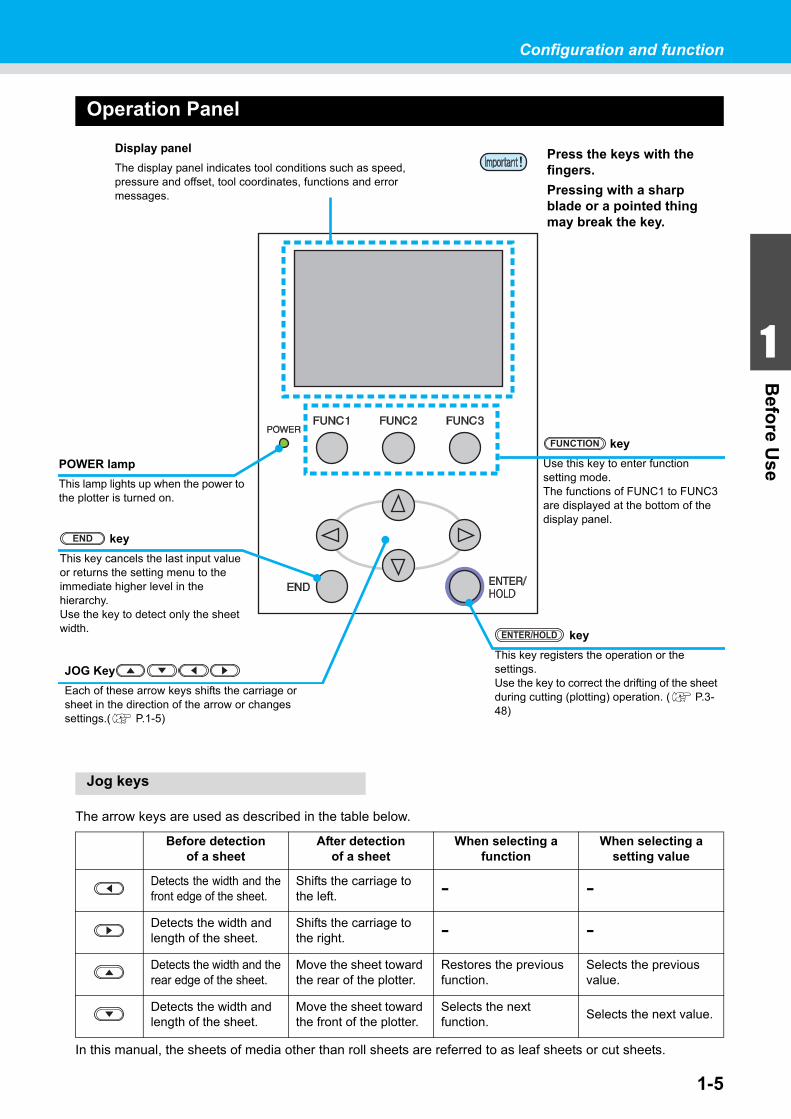
Operation Panel
Jog keys
The arrow keys are used as described in the table below.
In this manual, the sheets of media other than roll sheets are referred to as leaf sheets or cut sheets.
Before detectionof a sheet
After detectionof a sheet
When selecting a function
When selecting a setting value
Detects the width and thefront edge of the sheet.
Shifts the carriage to the left.
- -
Detects the width and length of the sheet.
Shifts the carriage to the right.
- -
Detects the width and therear edge of the sheet.
Move the sheet toward the rear of the plotter.
Restores the previous function.
Selects the previous value.
Detects the width and length of the sheet.
Move the sheet toward the front of the plotter.
Selects the next function.
Selects the next value.
key
Press this key to execute sheet feeding.( P.3-47)
FEED
key
This key switches the operation mode between REMOTE mode and LOCAL mode.If this key is pressed when the plotter is in operation, the plotter will come to a halt. Press the key again to restart the plotter,( P.1-11)
REMOTE
key
Use this key to select a tool and establish tool conditions. ( P.2-10)
TOOL key
Use this key for detection of the sheet or clearing of the detection result.( P.2-16)
SHEET SET key
Use this key for detection of the sheet or clearing of the detection result.( P.2-16)
SHEET SET
key
This key registers the operation or the settings.Use the key to correct the drifting of the sheet during cutting (plotting) operation. ( P.3-48)
ENTER/HOLD
Display panel
The display panel indicates tool conditions such as speed, pressure and offset, tool coordinates, functions and error messages.
POWER lamp
This lamp lights up when the power to the plotter is turned on.
key
Use this key to enter function setting mode.The functions of FUNC1 to FUNC3 are displayed at the bottom of the display panel.
FUNCTION
key
This key cancels the last input value or returns the setting menu to the immediate higher level in the hierarchy.Use the key to detect only the sheet width.
END
Press the keys with the fingers.
Pressing with a sharp blade or a pointed thing may break the key.
JOG Key
Each of these arrow keys shifts the carriage or sheet in the direction of the arrow or changes settings.( P.1-5)
1-6
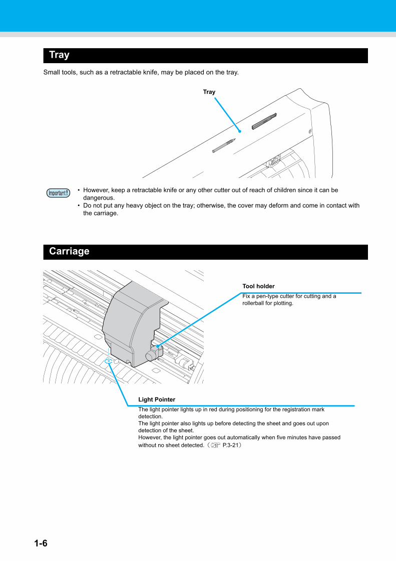
Tray
Small tools, such as a retractable knife, may be placed on the tray.
Carriage
• However, keep a retractable knife or any other cutter out of reach of children since it can be dangerous.
• Do not put any heavy object on the tray; otherwise, the cover may deform and come in contact with the carriage.
Tray
Light Pointer
The light pointer lights up in red during positioning for the registration mark detection.The light pointer also lights up before detecting the sheet and goes out upon detection of the sheet.However, the light pointer goes out automatically when five minutes have passed without no sheet detected.( P.3-21)
Tool holder
Fix a pen-type cutter for cutting and a rollerball for plotting.
Configuration and function
1-7
1
Befo
re Use
3
4
5
6
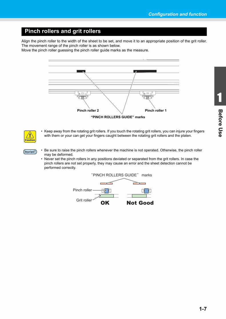
Pinch rollers and grit rollers
Align the pinch roller to the width of the sheet to be set, and move it to an appropriate position of the grit roller.The movement range of the pinch roller is as shown below.Move the pinch roller guessing the pinch roller guide marks as the measure.
• Keep away from the rotating grit rollers. If you touch the rotating grit rollers, you can injure your fingers with them or your can get your fingers caught between the rotating grit rollers and the platen.
• Be sure to raise the pinch rollers whenever the machine is not operated. Otherwise, the pinch roller may be deformed.
• Never set the pinch rollers in any positions deviated or separated from the grit rollers. In case the pinch rollers are not set properly, they may cause an error and the sheet detection cannot be performed correctly.
“PINCH ROLLERS GUIDE” marks
Pinch roller 2 Pinch roller 1
Not GoodOK
Configuration and function
1-8
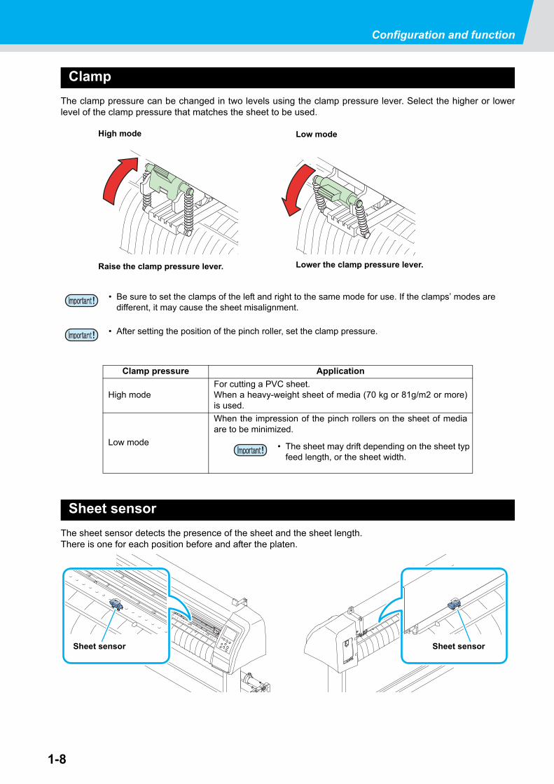
Clamp
The clamp pressure can be changed in two levels using the clamp pressure lever. Select the higher or lowerlevel of the clamp pressure that matches the sheet to be used.
Sheet sensor
The sheet sensor detects the presence of the sheet and the sheet length.There is one for each position before and after the platen.
• Be sure to set the clamps of the left and right to the same mode for use. If the clamps’ modes are different, it may cause the sheet misalignment.
• After setting the position of the pinch roller, set the clamp pressure.
Clamp pressure Application
High modeFor cutting a PVC sheet.When a heavy-weight sheet of media (70 kg or 81g/m2 or more)is used.
Low mode
When the impression of the pinch rollers on the sheet of mediaare to be minimized.
High mode Low mode
Raise the clamp pressure lever. Lower the clamp pressure lever.
• The sheet may drift depending on the sheet typfeed length, or the sheet width.
Sheet sensorSheet sensor

1-9
1
Befo
re Use
3
4
5
6
Connecting the cablesThis plotter uses the USB, LAN and RS232C connector for connection to the host computer.
USB Cable Connection
When connecting the USB cable, you must observe the followings.
Connecting USB driver
As for USB driver connection, refer to “USB Driver Installation Guide” in the FineCut supplied with this machine.
(1) Set the supplied CD for FineCut into the disk drive.(2) Click [CD-ROM Contents] on the menu.(3) Open [InstallGuid(en).pdf] for the plotter used in [Mimaki Device Driver] folder.
RS-232C Cable Connection
When you want to connect the RS-232C cable, you must observe the following notabilia.
LAN Cable connection
When connecting LAN cable, be sure to follow the note below:
• Connect or disconnect the connectors carefully. Applying undue force to a connector may damage the connector.
• Do not plug in or unplug any cable during data transferring.• Follow the instructions on the LCD if the wizard is displayed when connecting the USB cable.
• When connecting the cables, turn off first the power to the device and that tothe host computer which the power cable is to be connected.
• Do not plug in or unplug any cable during data transferring.
• Surely insert LAN cable until clicking noise sounds.• Do not plug in or unplug any cable during data transferring.
Connecting the cables
1-10
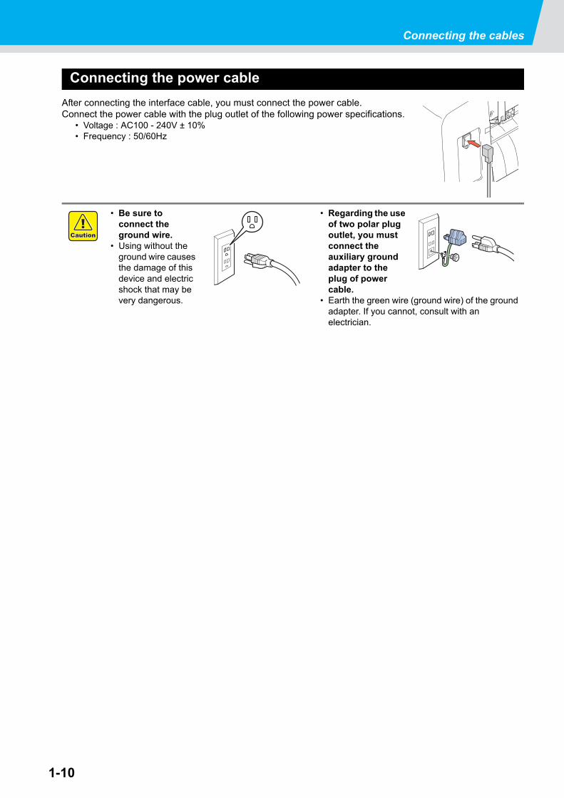
Connecting the power cable
After connecting the interface cable, you must connect the power cable.Connect the power cable with the plug outlet of the following power specifications.
• Voltage : AC100 - 240V ± 10%• Frequency : 50/60Hz
• Be sure to connect the ground wire.
• Using without the ground wire causes the damage of this device and electric shock that may be very dangerous.
• Regarding the use of two polar plug outlet, you must connect the auxiliary ground adapter to the plug of power cable.
• Earth the green wire (ground wire) of the ground adapter. If you cannot, consult with an electrician.
1-11
1
Befo
re Use
3
4
5
6
Menu modeThis plotter is provided with the following four modes:
< NOT-READY > mode
The plotter is in this mode until the media is detected.The keys other than the key are effective.
< LOCAL > mode
The plotter enters this mode after the sheet detection.All the keys are effective.The plotter can receive data from the computer. However, data processing of cutting (plotting) and similar datais not performed.(Doing so could result in a processing error depending on the application software.)
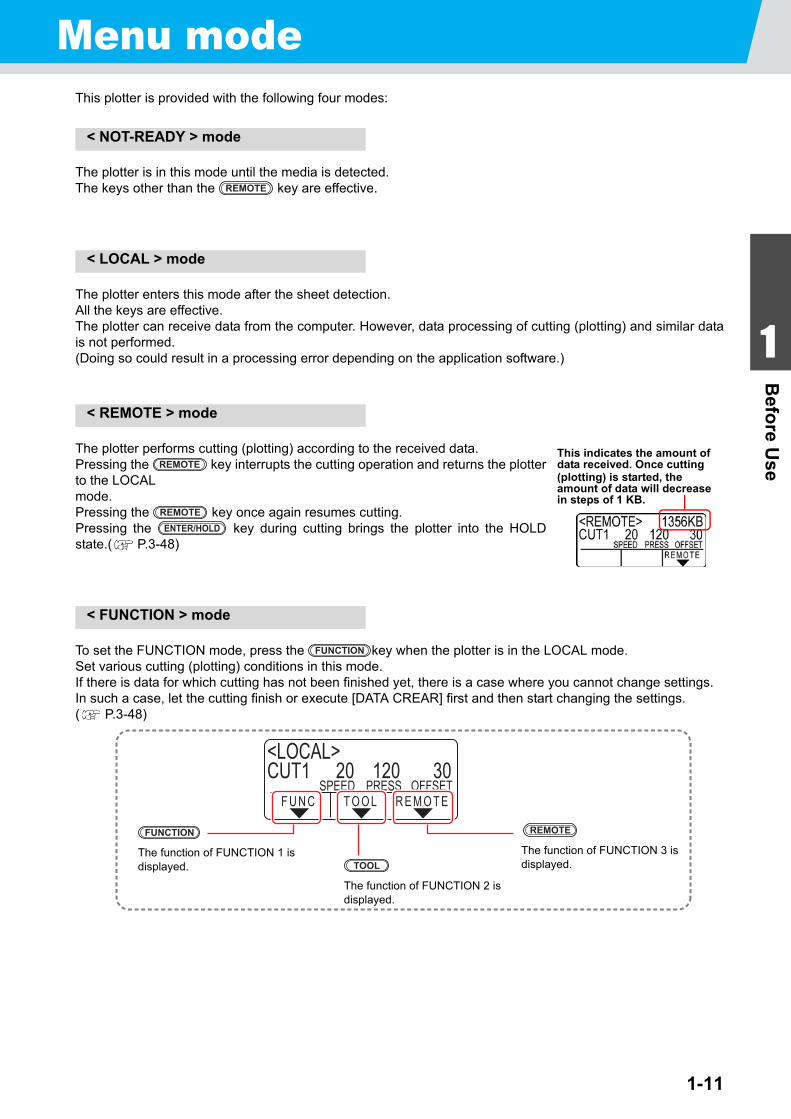
< REMOTE > mode
The plotter performs cutting (plotting) according to the received data.Pressing the key interrupts the cutting operation and returns the plotterto the LOCALmode.Pressing the key once again resumes cutting.Pressing the key during cutting brings the plotter into the HOLDstate.( P.3-48)
< FUNCTION > mode
To set the FUNCTION mode, press the key when the plotter is in the LOCAL mode.Set various cutting (plotting) conditions in this mode.If there is data for which cutting has not been finished yet, there is a case where you cannot change settings.In such a case, let the cutting finish or execute [DATA CREAR] first and then start changing the settings.( P.3-48)
REMOTE
This indicates the amount of data received. Once cutting (plotting) is started, the amount of data will decrease in steps of 1 KB.
REMOTE
REMOTEENTER/HOLD
FUNCTION
<LOCAL>CUT1 20 120 30
R E M O T ET O O LF U N CSPEED PRESS OFFSET
The function of FUNCTION 1 is displayed.
FUNCTION
The function of FUNCTION 2 is displayed.
TOOLThe function of FUNCTION 3 is displayed.
REMOTE

1-12

This chapter describes the procedures and settings ranging fromtool installation to cutting (plotting) operation.
Installing a tool..................................................................... 2-3Using a cutter ..............................................................................2-3How to Install a Ballpoint Pen .....................................................2-6
Turning the power on .......................................................... 2-8Setting the tool conditions.................................................. 2-9
Kinds of the Tool Conditions .......................................................2-9Select the tool condition ............................................................2-10Set the Tool Conditions .............................................................2-10
Setting a sheet ................................................................... 2-14Setting a leaf sheet (cut sheet) .................................................2-17How to Place the Roll Sheet (CG-60SRIII) ...............................2-18How to Place the Roll Sheet (CG-100SRIII/CG-130SRIII) ........2-20
Test cutting (plotting) ........................................................ 2-23Cutting (plotting)................................................................ 2-25
Setting the origin .......................................................................2-25Start cutting (plotting) ................................................................2-26Cut off the Sheet (Manual Cutting) ...........................................2-27
Turning the power off ........................................................ 2-28
CHAPTER 2
Basic Operations
2-2
Operation flow
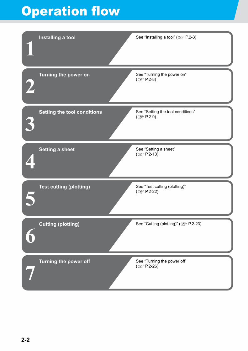
1Installing a tool
2Turning the power on
3Setting the tool conditions
4Setting a sheet
5Test cutting (plotting)
6Cutting (plotting)
See “Installing a tool” ( P.2-3)
See “Turning the power on” ( P.2-8)
See “Setting the tool conditions” ( P.2-9)
See “Setting a sheet” ( P.2-13)
See “Test cutting (plotting)” ( P.2-22)
See “Cutting (plotting)” ( P.2-23)
7Turning the power off See “Turning the power off”
( P.2-26)
2-3
1
2
Basic O
peratio
ns
4
5
6
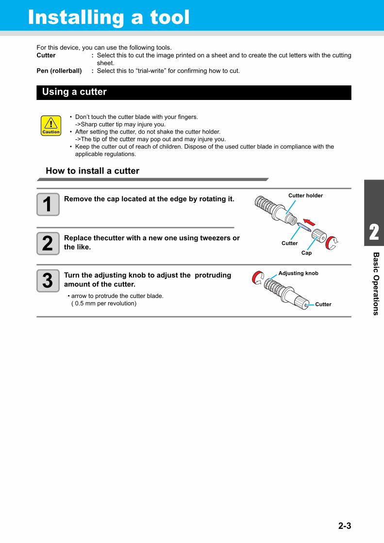
Installing a toolFor this device, you can use the following tools.Cutter : Select this to cut the image printed on a sheet and to create the cut letters with the cutting
sheet.Pen (rollerball) : Select this to “trial-write” for confirming how to cut.
Using a cutter
How to install a cutter
1 Remove the cap located at the edge by rotating it.
2 Replace thecutter with a new one using tweezers or the like.
3 Turn the adjusting knob to adjust the protruding amount of the cutter.
• arrow to protrude the cutter blade. ( 0.5 mm per revolution)
• Don’t touch the cutter blade with your fingers.->Sharp cutter tip may injure you.
• After setting the cutter, do not shake the cutter holder.->The tip of the cutter may pop out and may injure you.
• Keep the cutter out of reach of children. Dispose of the used cutter blade in compliance with the applicable regulations.
Cutter holder
Cutter
Cap
Cutter
Adjusting knob
2-4
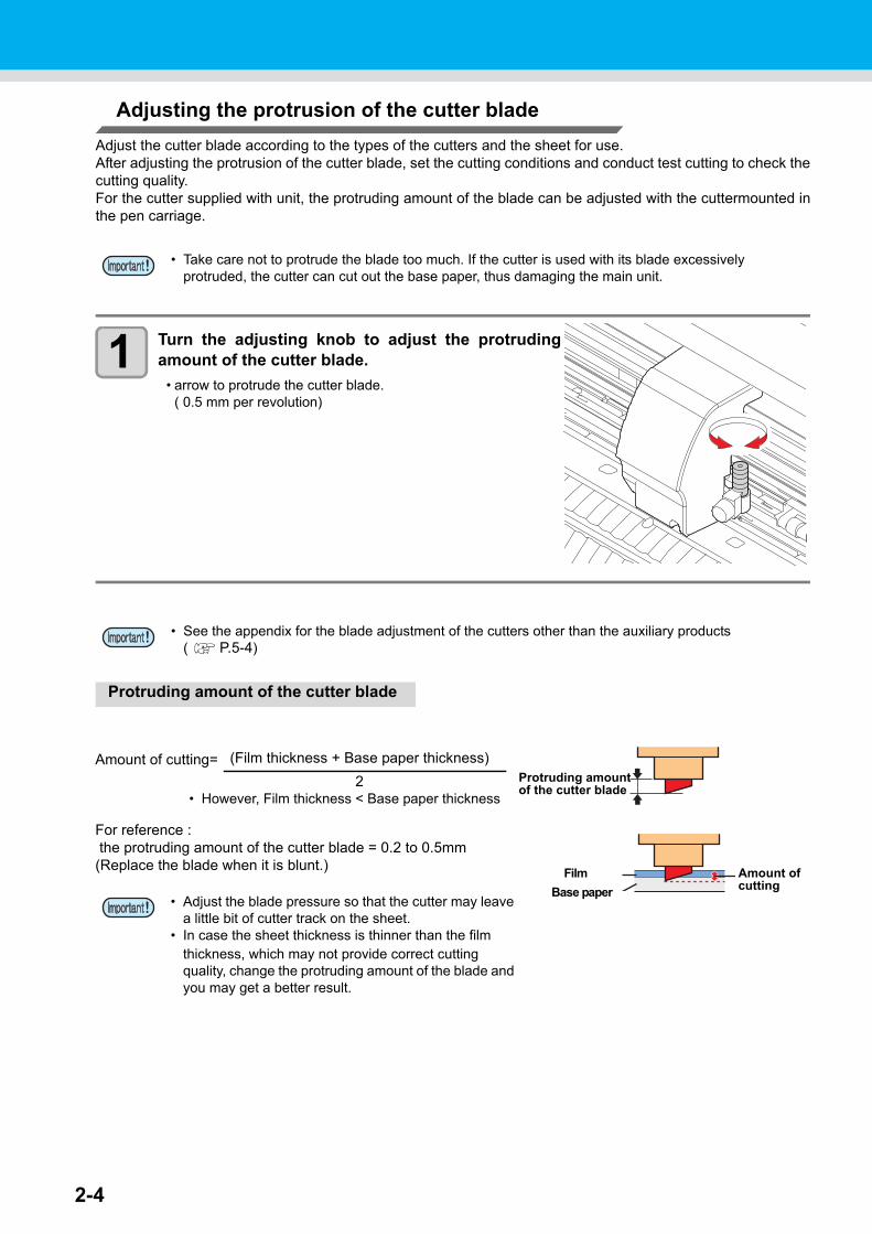
Adjusting the protrusion of the cutter blade
Adjust the cutter blade according to the types of the cutters and the sheet for use.After adjusting the protrusion of the cutter blade, set the cutting conditions and conduct test cutting to check thecutting quality.For the cutter supplied with unit, the protruding amount of the blade can be adjusted with the cuttermounted inthe pen carriage.
1 Turn the adjusting knob to adjust the protrudingamount of the cutter blade.
• arrow to protrude the cutter blade. ( 0.5 mm per revolution)
Protruding amount of the cutter blade
• Take care not to protrude the blade too much. If the cutter is used with its blade excessively protruded, the cutter can cut out the base paper, thus damaging the main unit.
• See the appendix for the blade adjustment of the cutters other than the auxiliary products ( P.5-4)
Amount of cutting=
For reference : the protruding amount of the cutter blade = 0.2 to 0.5mm(Replace the blade when it is blunt.)
• Adjust the blade pressure so that the cutter may leave a little bit of cutter track on the sheet.
• In case the sheet thickness is thinner than the film thickness, which may not provide correct cutting quality, change the protruding amount of the blade and you may get a better result.
Protruding amountof the cutter blade
Amount of cutting
Film
Base paper
(Film thickness + Base paper thickness)
2• However, Film thickness < Base paper thickness
2-5
1
2
Basic O
peratio
ns
4
5
6
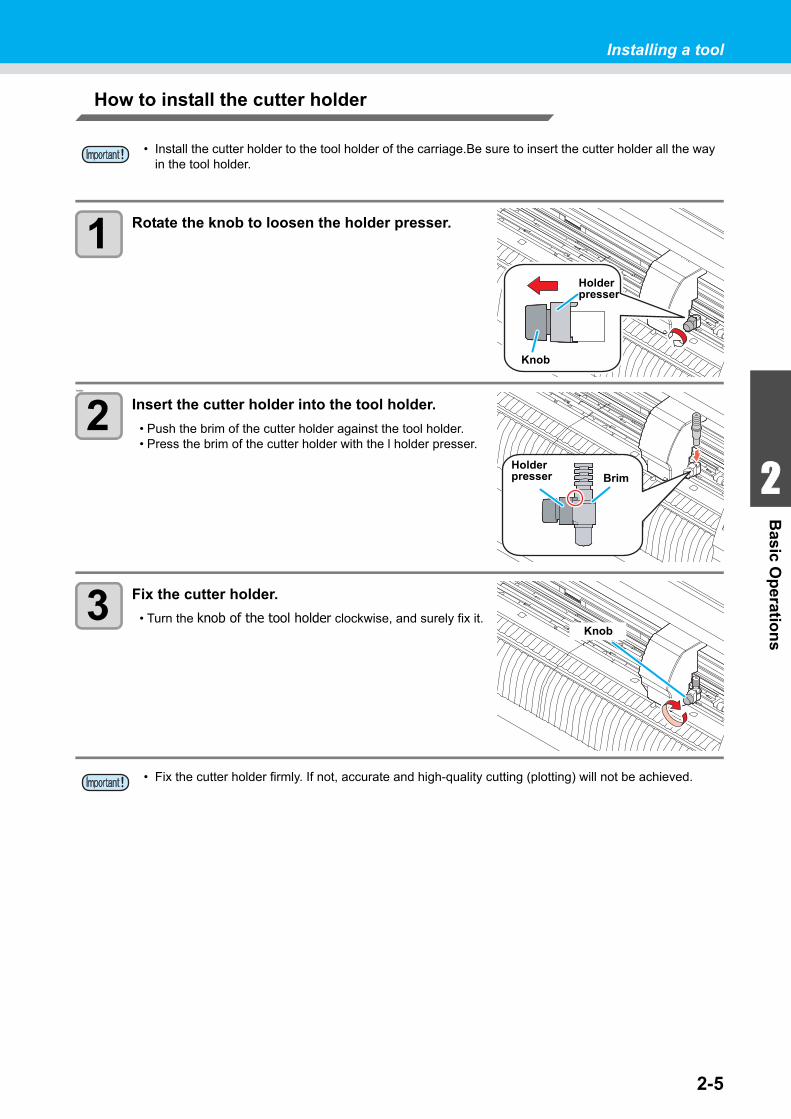
Installing a tool
How to install the cutter holder
1 Rotate the knob to loosen the holder presser.
holder
2 Insert the cutter holder into the tool holder.
• Push the brim of the cutter holder against the tool holder.• Press the brim of the cutter holder with the l holder presser.
3 Fix the cutter holder.
• Turn the knob of the tool holder clockwise, and surely fix it.
• Install the cutter holder to the tool holder of the carriage.Be sure to insert the cutter holder all the way in the tool holder.
• Fix the cutter holder firmly. If not, accurate and high-quality cutting (plotting) will not be achieved.
Holder presser
Knob
BrimHolder presser
Knob
2-6
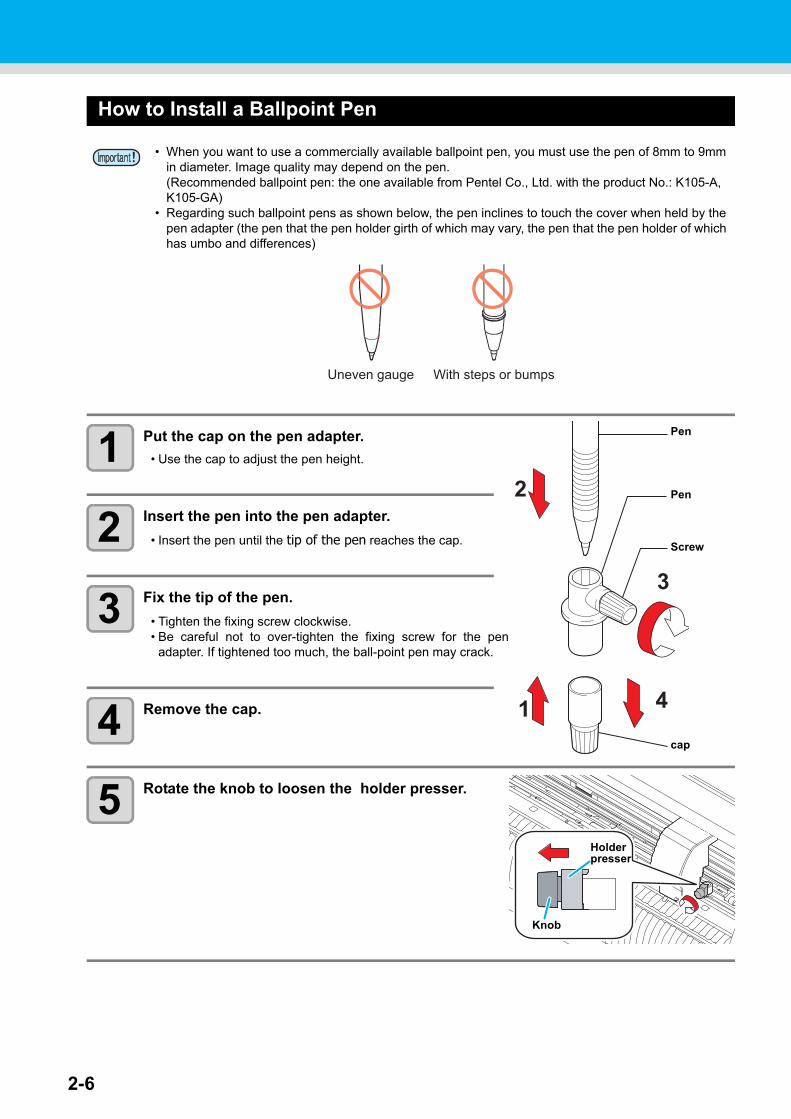
How to Install a Ballpoint Pen
1 Put the cap on the pen adapter.
• Use the cap to adjust the pen height.
2 Insert the pen into the pen adapter.
• Insert the pen until the tip of the pen reaches the cap.
3 Fix the tip of the pen.
• Tighten the fixing screw clockwise.• Be careful not to over-tighten the fixing screw for the pen
adapter. If tightened too much, the ball-point pen may crack.
4 Remove the cap.
5 Rotate the knob to loosen the holder presser.
• When you want to use a commercially available ballpoint pen, you must use the pen of 8mm to 9mm in diameter. Image quality may depend on the pen.(Recommended ballpoint pen: the one available from Pentel Co., Ltd. with the product No.: K105-A, K105-GA)
• Regarding such ballpoint pens as shown below, the pen inclines to touch the cover when held by the pen adapter (the pen that the pen holder girth of which may vary, the pen that the pen holder of which has umbo and differences)
Uneven gauge With steps or bumps
1
2
4
3
Pen
Pen
Screw
cap
Holder presser
Knob

Installing a tool
2-7
1
2
Basic O
peratio
ns
4
5
6
6 Insert the pen adapter with the pen into the tool holder.
• Make sure that the brim of the pen adapter is rested on the toolholder.
• Set the adapter in such a way that the fixing screw will notobstruct operation.
• Press the brim of the pen adapter with the holder presser.
7 Turn the knob clockwise to fix the tool.
Insert untilit is rested
Holder presser
Brim
2-8
Turning the power on
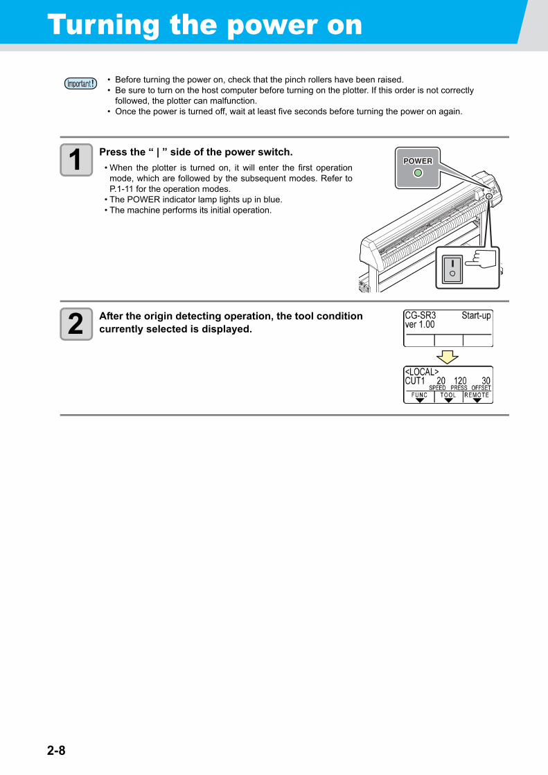
1 Press the “ | ” side of the power switch.
• When the plotter is turned on, it will enter the first operationmode, which are followed by the subsequent modes. Refer toP.1-11 for the operation modes.
• The POWER indicator lamp lights up in blue.• The machine performs its initial operation.
2 After the origin detecting operation, the tool condition currently selected is displayed.
• Before turning the power on, check that the pinch rollers have been raised.• Be sure to turn on the host computer before turning on the plotter. If this order is not correctly
followed, the plotter can malfunction.• Once the power is turned off, wait at least five seconds before turning the power on again.
2-9
1
2
Basic O
peratio
ns
4
5
6
Setting the tool conditionsYou can register the cutting speed and the pressure depending on the sheet or the tool type to be used. (Toolcondition)
Kinds of the Tool Conditions
A tool condition consists of cutting conditions (CUT1 to CUT7), printing-with-a-pen condition (PEN).
Kinds Description
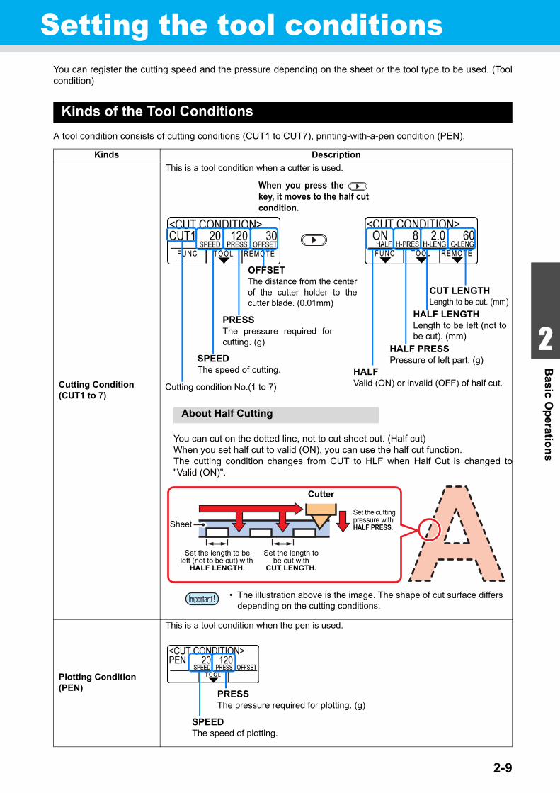
Cutting Condition (CUT1 to 7)
This is a tool condition when a cutter is used.
About Half Cutting
You can cut on the dotted line, not to cut sheet out. (Half cut)When you set half cut to valid (ON), you can use the half cut function.The cutting condition changes from CUT to HLF when Half Cut is changed to"Valid (ON)".
Plotting Condition (PEN)
This is a tool condition when the pen is used.
OFFSETThe distance from the centerof the cutter holder to thecutter blade. (0.01mm)
PRESSThe pressure required forcutting. (g)
SPEEDThe speed of cutting.
Cutting condition No.(1 to 7)
When you press the key, it moves to the half cutcondition.
CUT LENGTHLength to be cut. (mm)
HALF LENGTHLength to be left (not tobe cut). (mm)
HALF PRESSPressure of left part. (g)
HALFValid (ON) or invalid (OFF) of half cut.
Cutter
Set the length to be left (not to be cut) with
HALF LENGTH.
Sheet
Set the length to be cut with
CUT LENGTH.
Set the cutting pressure with HALF PRESS.
• The illustration above is the image. The shape of cut surface differs depending on the cutting conditions.
PRESSThe pressure required for plotting. (g)
SPEEDThe speed of plotting.
2-10
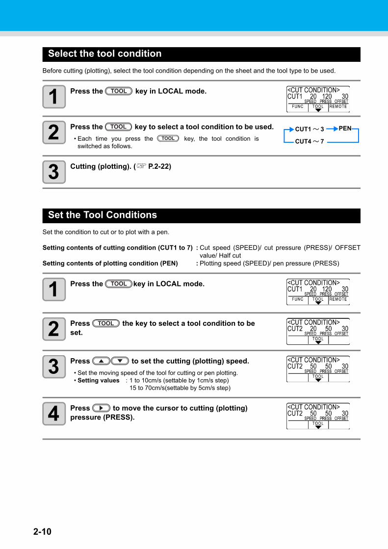
Select the tool condition
Before cutting (plotting), select the tool condition depending on the sheet and the tool type to be used.
1 Press the key in LOCAL mode.
2 Press the key to select a tool condition to be used.
• Each time you press the key, the tool condition isswitched as follows.
3 Cutting (plotting). ( P.2-22)
Set the Tool Conditions
Set the condition to cut or to plot with a pen.
Setting contents of cutting condition (CUT1 to 7) : Cut speed (SPEED)/ cut pressure (PRESS)/ OFFSETvalue/ Half cut
Setting contents of plotting condition (PEN) : Plotting speed (SPEED)/ pen pressure (PRESS)
1 Press the key in LOCAL mode.
2 Press the key to select a tool condition to be set.
3 Press to set the cutting (plotting) speed.
• Set the moving speed of the tool for cutting or pen plotting.• Setting values : 1 to 10cm/s (settable by 1cm/s step)
15 to 70cm/s(settable by 5cm/s step)
4 Press to move the cursor to cutting (plotting) pressure (PRESS).
TOOL
TOOL CUT1 ~ 3 PEN
CUT4 ~ 7TOOL
TOOL
TOOL
2-11
1
2
Basic O
peratio
ns
4
5
6
Setting the tool conditions
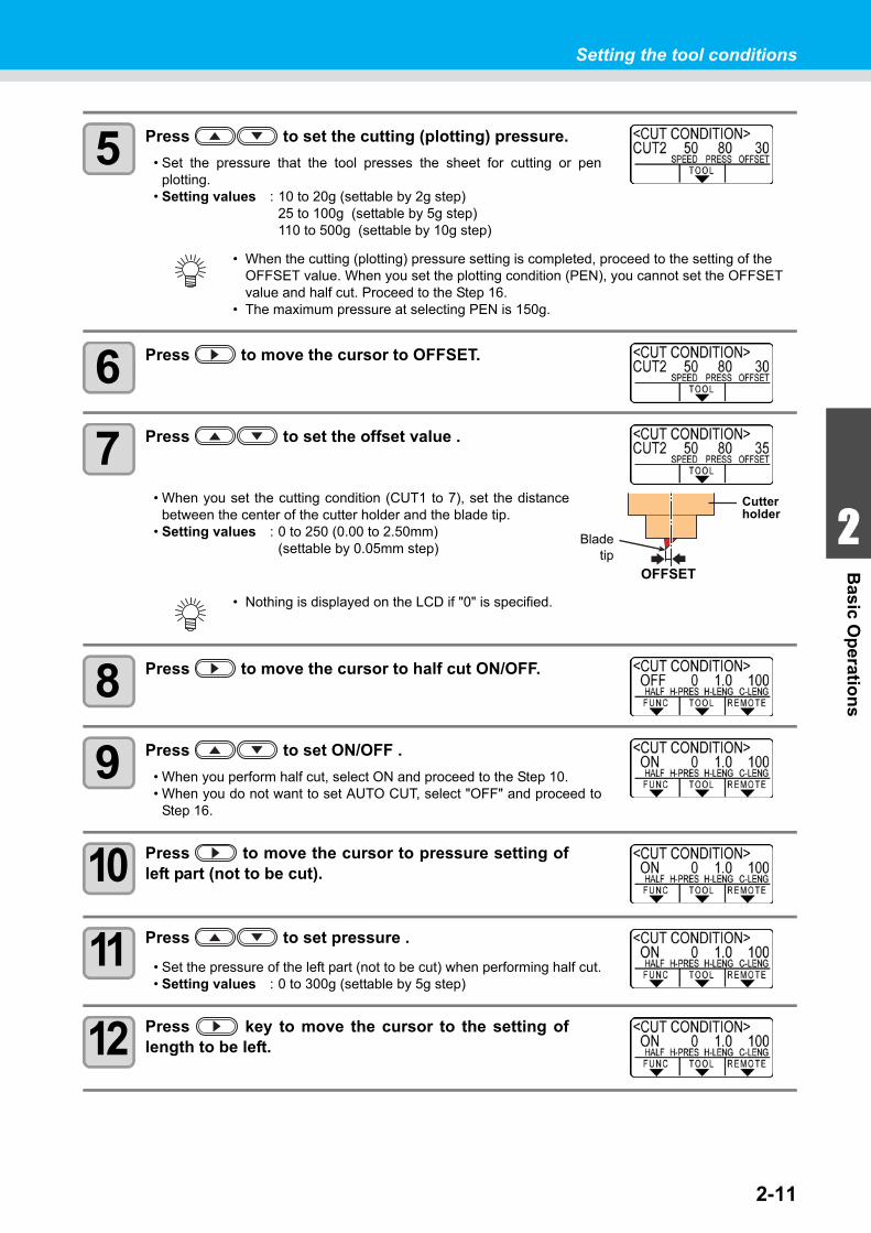
5 Press to set the cutting (plotting) pressure.
• Set the pressure that the tool presses the sheet for cutting or penplotting.
• Setting values : 10 to 20g (settable by 2g step)25 to 100g (settable by 5g step)110 to 500g (settable by 10g step)
6 Press to move the cursor to OFFSET.
7 Press to set the offset value .
• When you set the cutting condition (CUT1 to 7), set the distancebetween the center of the cutter holder and the blade tip.
• Setting values : 0 to 250 (0.00 to 2.50mm) (settable by 0.05mm step)
8 Press to move the cursor to half cut ON/OFF.
9 Press to set ON/OFF .
• When you perform half cut, select ON and proceed to the Step 10.• When you do not want to set AUTO CUT, select "OFF" and proceed to
Step 16.
10 Press to move the cursor to pressure setting ofleft part (not to be cut).
11 Press to set pressure .
• Set the pressure of the left part (not to be cut) when performing half cut.• Setting values : 0 to 300g (settable by 5g step)
12 Press key to move the cursor to the setting oflength to be left.
• When the cutting (plotting) pressure setting is completed, proceed to the setting of the OFFSET value. When you set the plotting condition (PEN), you cannot set the OFFSET value and half cut. Proceed to the Step 16.
• The maximum pressure at selecting PEN is 150g.
• Nothing is displayed on the LCD if "0" is specified.
Cutter holder
OFFSET
Bladetip
2-12
Setting the tool conditions
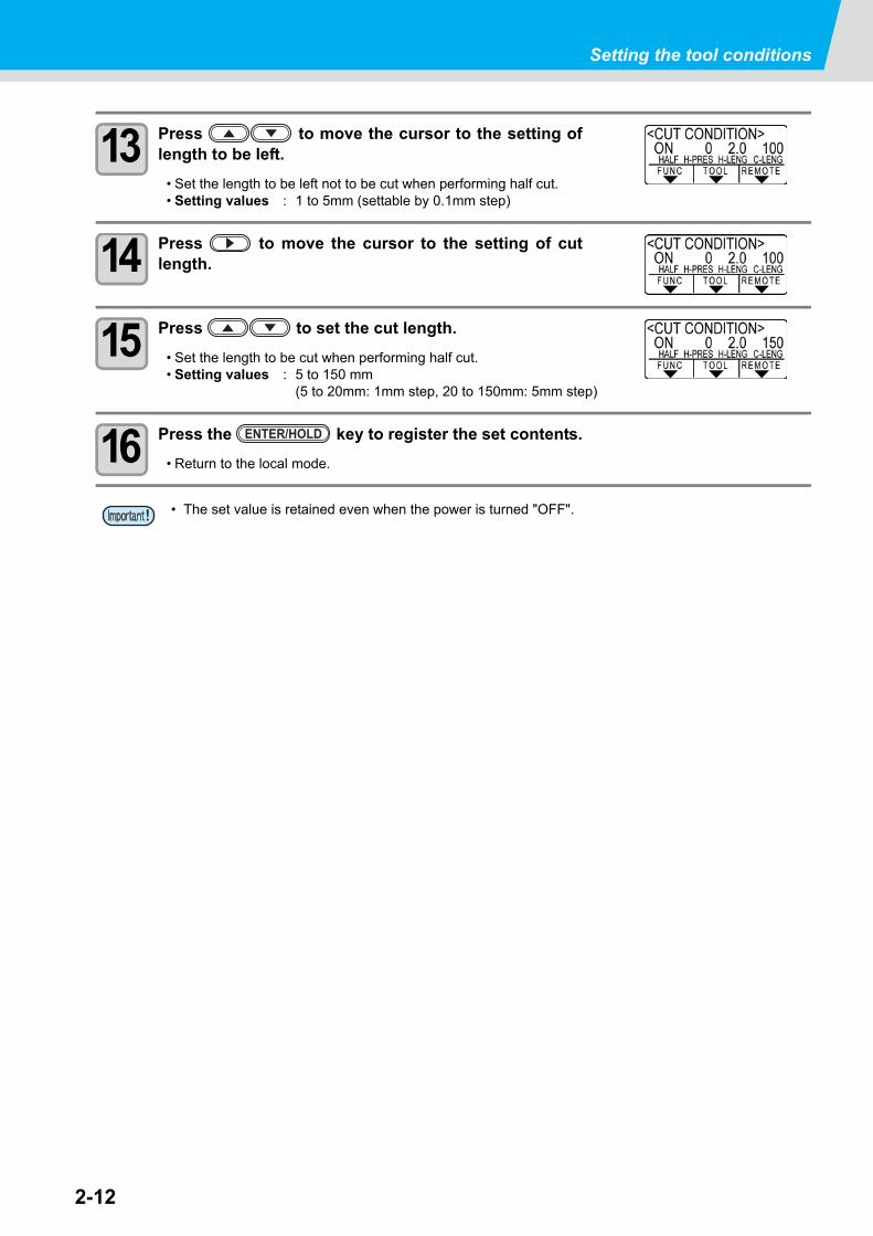
13 Press to move the cursor to the setting oflength to be left.
• Set the length to be left not to be cut when performing half cut.• Setting values : 1 to 5mm (settable by 0.1mm step)
14 Press to move the cursor to the setting of cutlength.
15 Press to set the cut length.
• Set the length to be cut when performing half cut.• Setting values : 5 to 150 mm
(5 to 20mm: 1mm step, 20 to 150mm: 5mm step)
16 Press the key to register the set contents.
• Return to the local mode.
• The set value is retained even when the power is turned "OFF".
ENTER/HOLD
2-13
1
2
Basic O
peratio
ns
4
5
6
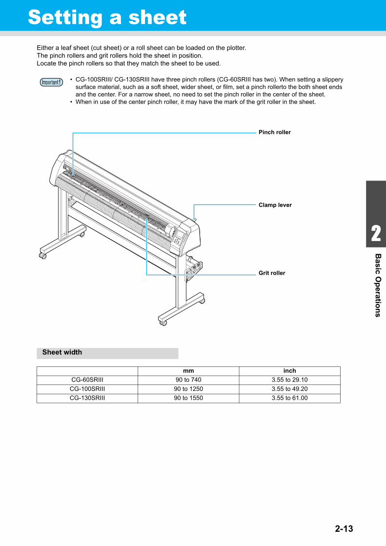
Setting a sheetEither a leaf sheet (cut sheet) or a roll sheet can be loaded on the plotter.The pinch rollers and grit rollers hold the sheet in position.Locate the pinch rollers so that they match the sheet to be used.
Sheet width
• CG-100SRIII/ CG-130SRIII have three pinch rollers (CG-60SRIII has two). When setting a slippery surface material, such as a soft sheet, wider sheet, or film, set a pinch rollerto the both sheet ends and the center. For a narrow sheet, no need to set the pinch roller in the center of the sheet.
• When in use of the center pinch roller, it may have the mark of the grit roller in the sheet.
mm inch
CG-60SRIII 90 to 740 3.55 to 29.10
CG-100SRIII 90 to 1250 3.55 to 49.20
CG-130SRIII 90 to 1550 3.55 to 61.00
Pinch roller
Clamp lever
Grit roller
2-14
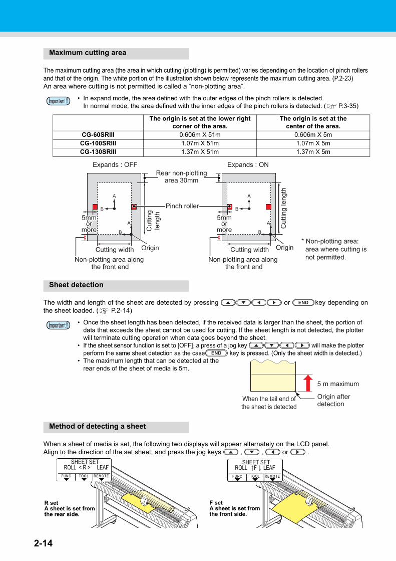
Maximum cutting area
The maximum cutting area (the area in which cutting (plotting) is permitted) varies depending on the location of pinch rollersand that of the origin. The white portion of the illustration shown below represents the maximum cutting area. (P.2-23)An area where cutting is not permitted is called a “non-plotting area”.
Sheet detection
The width and length of the sheet are detected by pressing or key depending onthe sheet loaded. ( P.2-14)
Method of detecting a sheet
When a sheet of media is set, the following two displays will appear alternately on the LCD panel.Align to the direction of the set sheet, and press the jog keys , , or .
• In expand mode, the area defined with the outer edges of the pinch rollers is detected. In normal mode, the area defined with the inner edges of the pinch rollers is detected. ( P.3-35)
The origin is set at the lower right corner of the area.
The origin is set at thecenter of the area.
CG-60SRIII 0.606m X 51m 0.606m X 5mCG-100SRIII 1.07m X 51m 1.07m X 5mCG-130SRIII 1.37m X 51m 1.37m X 5m
• Once the sheet length has been detected, if the received data is larger than the sheet, the portion of data that exceeds the sheet cannot be used for cutting. If the sheet length is not detected, the plotter will terminate cutting operation when data goes beyond the sheet.
• If the sheet sensor function is set to [OFF], a press of a jog key will make the plotter perform the same sheet detection as the case key is pressed. (Only the sheet width is detected.)
• The maximum length that can be detected at the rear ends of the sheet of media is 5m.
5mm5mmoror
moremore
5mmor
more
Cutting width Origin Cutting width
Expands : OFF Expands : ON
Origin
Cut
ting
leng
th
Cut
ting
leng
th
Non-plotting area along the front end
* Non-plotting area:area where cutting is not permitted.
Pinch roller
Rear non-plottingarea 30mm
Non-plotting area along the front end
5mm5mmoror
moremore
5mmor
more
END
END
Origin after detection
5 m maximum
When the tail end ofthe sheet is detected
R setA sheet is set from the rear side.
F setA sheet is set from the front side.
<>
2-15
1
2
Basic O
peratio
ns
4
5
6
Setting a sheet
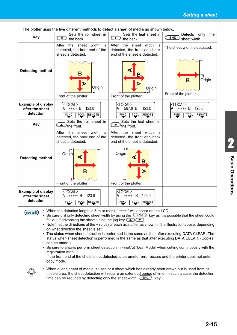
The plotter uses the five different methods to detect a sheet of media as shown below.
KeySets the roll sheet inthe back.
Sets the leaf sheet inthe back.
Detects only thesheet width.
Detecting method
After the sheet width isdetected, the front end of thesheet is detected.
Front of the plotter
After the sheet width isdetected, the front and backend of the sheet is detected.
Front of the plotter
The sheet width is detected.
Front of the plotter
Example of display after the sheet
detection
KeySets the roll sheet inthe front.
Sets the leaf sheet inthe front.
Detecting method
After the sheet width isdetected, the back end of thesheet is detected.
Front of the plotter
After the sheet width isdetected, the front and backend of the sheet is detected.
Front of the plotter
Example of display after the sheet
detection
• When the detected length is 3 m or more, “ ∗∗∗∗ ” will appear on the LCD.• Be careful if only detecting sheet width by using the key as it is possible that the sheet could
fall out if advancing the sheet using the jog key .• Note that the directions of the + (plus) of each axis differ as shown in the illustration above, depending
on what direction the sheet is set.• The status when sheet detection is performed is the same as that after executing DATA CLEAR. The
status when sheet detection is performed is the same as that after executing DATA CLEAR. (Copies can be made.)
• Be sure to always perform sheet detection in FineCut “Leaf Mode” when cutting continuously with the registration mark.If the front end of the sheet is not detected, a parameter error occurs and the printer does not enter copy mode.
• When a long sheet of media is used or a sheet which has already been drawn out is used from its middle area, the sheet detection will require an extended period of time. In such a case, the detection time can be reduced by detecting only the sheet width key.
END
B
Origin
A
A
A
B
Origin
B OriginA
B
Origin
B
A
A
Origin
END
END
2-16
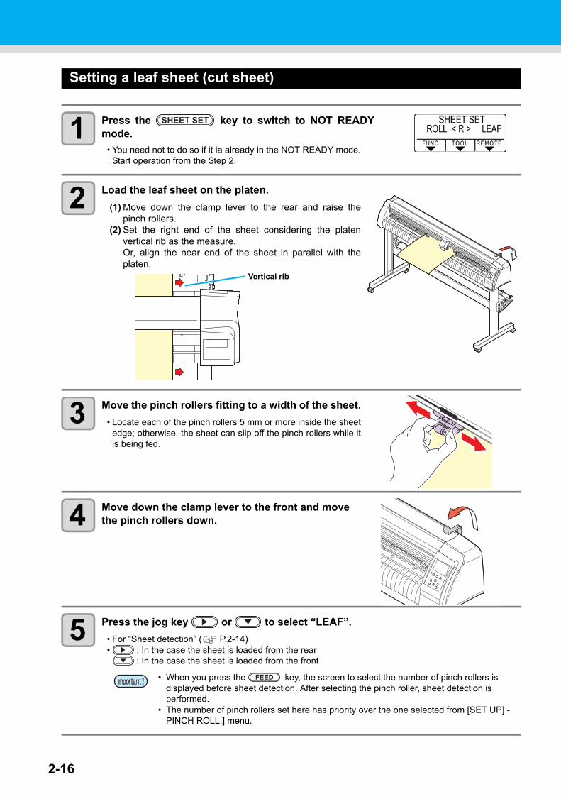
Setting a leaf sheet (cut sheet)
1 Press the key to switch to NOT READYmode.
• You need not to do so if it ia already in the NOT READY mode.Start operation from the Step 2.
2 Load the leaf sheet on the platen.
(1) Move down the clamp lever to the rear and raise thepinch rollers.
(2) Set the right end of the sheet considering the platenvertical rib as the measure.Or, align the near end of the sheet in parallel with theplaten.
3 Move the pinch rollers fitting to a width of the sheet.
• Locate each of the pinch rollers 5 mm or more inside the sheetedge; otherwise, the sheet can slip off the pinch rollers while itis being fed.
4 Move down the clamp lever to the front and move the pinch rollers down.
5 Press the jog key or to select “LEAF”.
• For “Sheet detection” ( P.2-14)• : In the case the sheet is loaded from the rear
: In the case the sheet is loaded from the front
• When you press the key, the screen to select the number of pinch rollers is displayed before sheet detection. After selecting the pinch roller, sheet detection is performed.
• The number of pinch rollers set here has priority over the one selected from [SET UP] - PINCH ROLL.] menu.
SHEET SET
Vertical rib
FEED
2-17
1
2
Basic O
peratio
ns
4
5
6
Setting a sheet
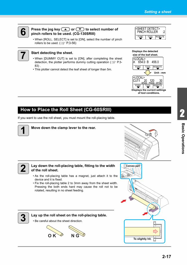
6 Press the jog key or to select number of pinch rollers to be used. (CG-130SRIII)
• When [ROLL. SELECT] is set to [ON], select the number of pinchrollers to be used. ( P.3-56)
7 Start detecting the sheet.
• When [DUMMY CUT] is set to [ON], after completing the sheetdetection, the plotter performs dummy cutting operation ( P.3-83) .
• This plotter cannot detect the leaf sheet of longer than 5m.
How to Place the Roll Sheet (CG-60SRIII)
If you want to use the roll sheet, you must mount the roll-placing table.
1 Move down the clamp lever to the rear.
2 Lay down the roll-placing table, fitting to the width of the roll sheet.
• As the roll-placing table has a magnet, just attach it to thedevice and it is fixed.
• Fix the roll-placing table 2 to 3mm away from the sheet width.Pressing the both ends hard may cause the roll not to berotated, resulting in no sheet feeding.
3 Lay up the roll sheet on the roll-placing table.
• Be careful about the sheet direction.
Unit : mm
Displays the detected
size of the leaf sheet.
Displays the current settings of tool conditions.
To slightly hit.
Convex part
O K N G
2-18
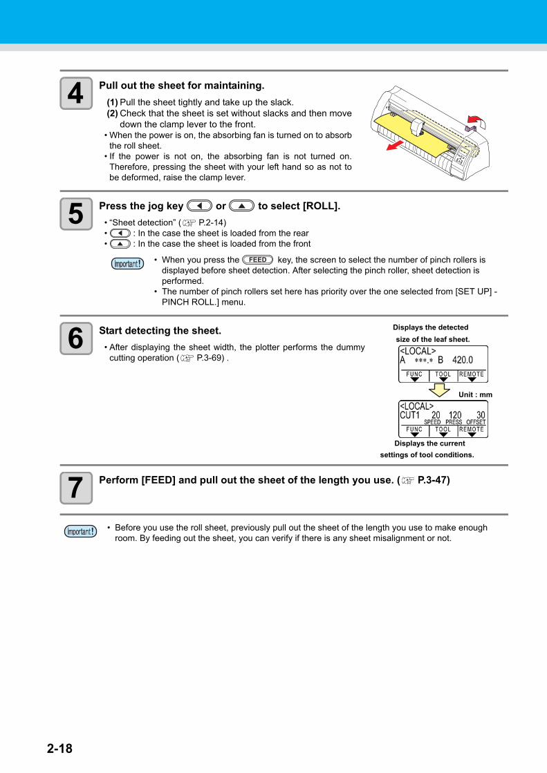
4 Pull out the sheet for maintaining.
(1) Pull the sheet tightly and take up the slack.(2) Check that the sheet is set without slacks and then move
down the clamp lever to the front.• When the power is on, the absorbing fan is turned on to absorb
the roll sheet.• If the power is not on, the absorbing fan is not turned on.
Therefore, pressing the sheet with your left hand so as not tobe deformed, raise the clamp lever.
5 Press the jog key or to select [ROLL].
• “Sheet detection” ( P.2-14)• : In the case the sheet is loaded from the rear• : In the case the sheet is loaded from the front
6 Start detecting the sheet.
• After displaying the sheet width, the plotter performs the dummycutting operation ( P.3-69) .
7 Perform [FEED] and pull out the sheet of the length you use. ( P.3-47)
• When you press the key, the screen to select the number of pinch rollers is displayed before sheet detection. After selecting the pinch roller, sheet detection is performed.
• The number of pinch rollers set here has priority over the one selected from [SET UP] - PINCH ROLL.] menu.
• Before you use the roll sheet, previously pull out the sheet of the length you use to make enough room. By feeding out the sheet, you can verify if there is any sheet misalignment or not.
FEED
Unit : mm
size of the leaf sheet.
Displays the current
settings of tool conditions.
Displays the detected
2-19
1
2
Basic O
peratio
ns
4
5
6
Setting a sheet
How to Place the Roll Sheet (CG-100SRIII/CG-130SRIII)
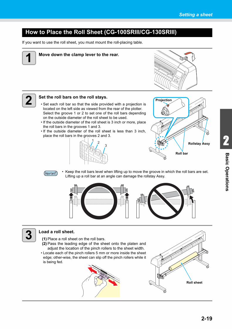
If you want to use the roll sheet, you must mount the roll-placing table.
1 Move down the clamp lever to the rear.
2 Set the roll bars on the roll stays.
• Set each roll bar so that the side provided with a projection islocated on the left side as viewed from the rear of the plotter.Select the groove 1 or 2 to set one of the roll bars dependingon the outside diameter of the roll sheet to be used.
• If the outside diameter of the roll sheet is 3 inch or more, placethe roll bars in the grooves 1 and 3.
• If the outside diameter of the roll sheet is less than 3 inch,place the roll bars in the grooves 2 and 3.
3 Load a roll sheet.
(1) Place a roll sheet on the roll bars.(2) Pass the leading edge of the sheet onto the platen and
adjust the location of the pinch rollers to the sheet width.• Locate each of the pinch rollers 5 mm or more inside the sheet
edge; other-wise, the sheet can slip off the pinch rollers while itis being fed.
• Keep the roll bars level when lifting up to move the groove in which the roll bars are set.Lifting up a roll bar at an angle can damage the rollstay Assy.
Roll bar
Rollstay Assy
Projection
1 23
Roll sheet
2-20
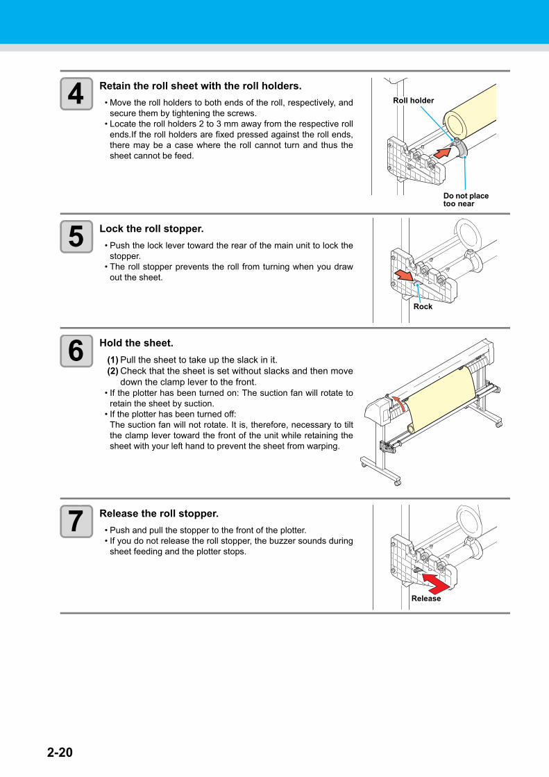
4 Retain the roll sheet with the roll holders.
• Move the roll holders to both ends of the roll, respectively, andsecure them by tightening the screws.
• Locate the roll holders 2 to 3 mm away from the respective rollends.If the roll holders are fixed pressed against the roll ends,there may be a case where the roll cannot turn and thus thesheet cannot be feed.
5 Lock the roll stopper.
• Push the lock lever toward the rear of the main unit to lock thestopper.
• The roll stopper prevents the roll from turning when you drawout the sheet.
6 Hold the sheet.
(1) Pull the sheet to take up the slack in it.(2) Check that the sheet is set without slacks and then move
down the clamp lever to the front.• If the plotter has been turned on: The suction fan will rotate to
retain the sheet by suction.• If the plotter has been turned off:
The suction fan will not rotate. It is, therefore, necessary to tiltthe clamp lever toward the front of the unit while retaining thesheet with your left hand to prevent the sheet from warping.
7 Release the roll stopper.
• Push and pull the stopper to the front of the plotter.• If you do not release the roll stopper, the buzzer sounds during
sheet feeding and the plotter stops.
Do not place too near
Roll holder
Rock
Release
2-21
1
2
Basic O
peratio
ns
4
5
6
Setting a sheet
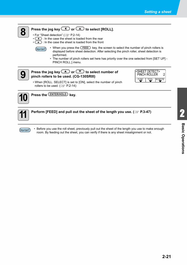
8 Press the jog key or to select [ROLL].
• For “Sheet detection” ( P.2-14)• : In the case the sheet is loaded from the rear• : In the case the sheet is loaded from the front
9 Press the jog key or to select number of pinch rollers to be used. (CG-130SRIII)
• When [ROLL. SELECT] is set to [ON], select the number of pinchrollers to be used. ( P.2-14)
10 Press the key.
11 Perform [FEED] and pull out the sheet of the length you use. ( P.3-47)
• When you press the key, the screen to select the number of pinch rollers is displayed before sheet detection. After selecting the pinch roller, sheet detection is performed.
• The number of pinch rollers set here has priority over the one selected from [SET UP] - PINCH ROLL.] menu.
• Before you use the roll sheet, previously pull out the sheet of the length you use to make enough room. By feeding out the sheet, you can verify if there is any sheet misalignment or not.
FEED
ENTER/HOLD
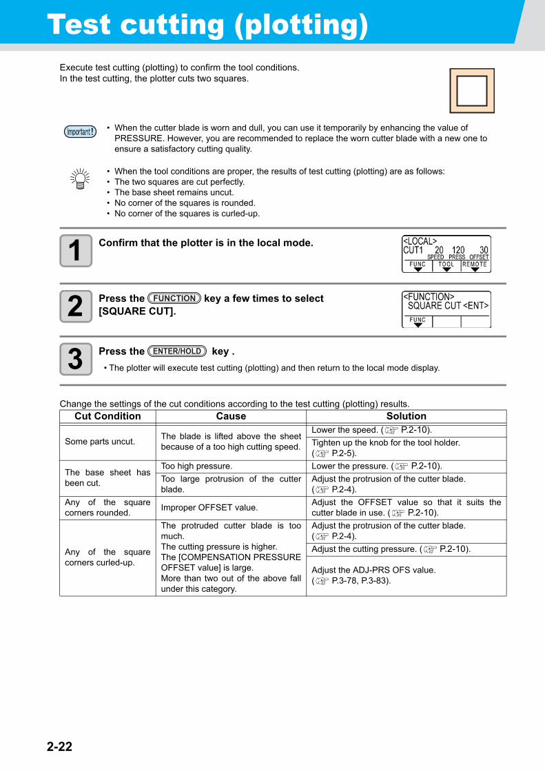
2-22
Test cutting (plotting)Execute test cutting (plotting) to confirm the tool conditions.In the test cutting, the plotter cuts two squares.
1 Confirm that the plotter is in the local mode.
2 Press the key a few times to select [SQUARE CUT].
3 Press the key .
• The plotter will execute test cutting (plotting) and then return to the local mode display.
Change the settings of the cut conditions according to the test cutting (plotting) results.
• When the cutter blade is worn and dull, you can use it temporarily by enhancing the value of PRESSURE. However, you are recommended to replace the worn cutter blade with a new one to ensure a satisfactory cutting quality.
• When the tool conditions are proper, the results of test cutting (plotting) are as follows:• The two squares are cut perfectly.• The base sheet remains uncut.• No corner of the squares is rounded.• No corner of the squares is curled-up.
Cut Condition Cause Solution
Some parts uncut.The blade is lifted above the sheetbecause of a too high cutting speed.
Lower the speed. ( P.2-10).
Tighten up the knob for the tool holder. ( P.2-5).
The base sheet hasbeen cut.
Too high pressure. Lower the pressure. ( P.2-10).
Too large protrusion of the cutterblade.
Adjust the protrusion of the cutter blade. ( P.2-4).
Any of the squarecorners rounded.
Improper OFFSET value.Adjust the OFFSET value so that it suits thecutter blade in use. ( P.2-10).
Any of the squarecorners curled-up.
The protruded cutter blade is toomuch.The cutting pressure is higher.The [COMPENSATION PRESSUREOFFSET value] is large.More than two out of the above fallunder this category.
Adjust the protrusion of the cutter blade. ( P.2-4).
Adjust the cutting pressure. ( P.2-10).
Adjust the ADJ-PRS OFS value. ( P.3-78, P.3-83).
FUNCTION
ENTER/HOLD
2-23
1
2
Basic O
peratio
ns
4
5
6
Cutting (plotting)You can start cutting (plotting) after completion of setting up a tool, a sheet and the tool conditions.
Setting the origin
The origin is a reference point for the cutting (plotting) data.When the origin is changed, set the new origin before starting cutting (plotting).
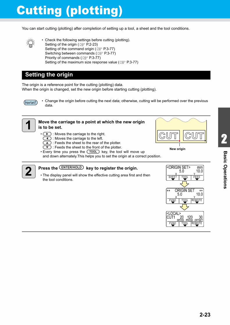
1 Move the carriage to a point at which the new originis to be set.
• : Moves the carriage to the right. : Moves the carriage to the left. : Feeds the sheet to the rear of the plotter. : Feeds the sheet to the front of the plotter.
• Every time you press the key, the tool will move upand down alternately.This helps you to set the origin at a correct position.
2 Press the key to register the origin.
• The display panel will show the effective cutting area first and thenthe tool conditions.
• Check the following settings before cutting (plotting).Setting of the origin ( P.2-23)Setting of the command origin ( P.3-77)Switching between commands ( P.3-77)Priority of commands ( P.3-77)Setting of the maximum size response value ( P.3-77)
• Change the origin before cutting the next data; otherwise, cutting will be performed over the previous data.
New originTOOL
ENTER/HOLD
2-24
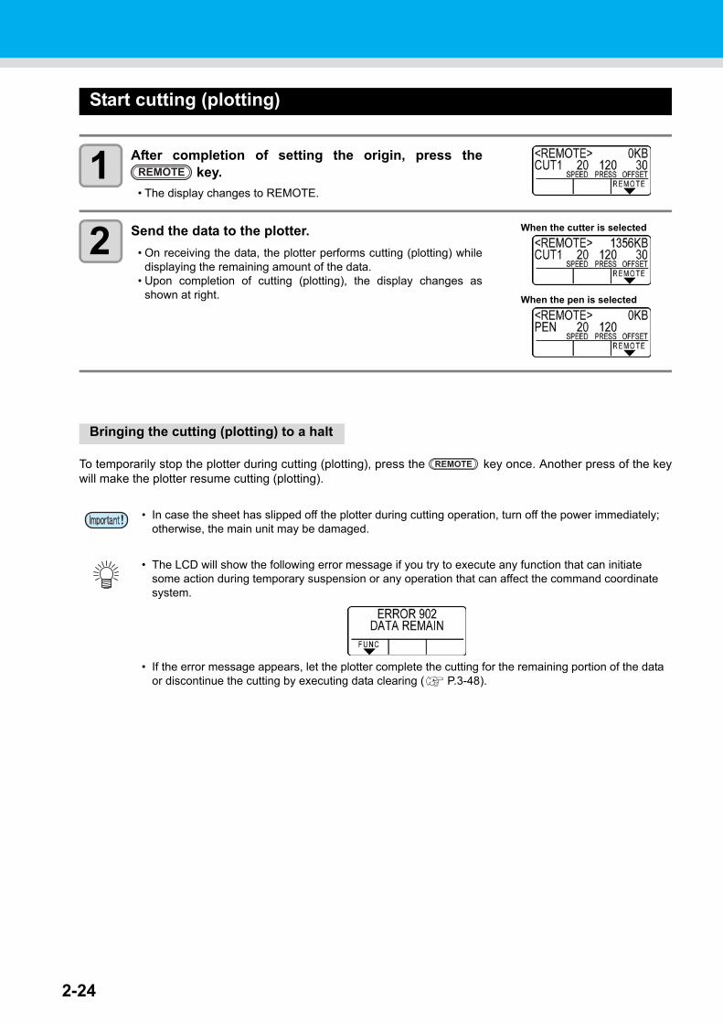
Start cutting (plotting)
1 After completion of setting the origin, press the key.
• The display changes to REMOTE.
2 Send the data to the plotter.
• On receiving the data, the plotter performs cutting (plotting) whiledisplaying the remaining amount of the data.
• Upon completion of cutting (plotting), the display changes asshown at right.
Bringing the cutting (plotting) to a halt
To temporarily stop the plotter during cutting (plotting), press the key once. Another press of the keywill make the plotter resume cutting (plotting).
• In case the sheet has slipped off the plotter during cutting operation, turn off the power immediately; otherwise, the main unit may be damaged.
• The LCD will show the following error message if you try to execute any function that can initiate some action during temporary suspension or any operation that can affect the command coordinate system.
• If the error message appears, let the plotter complete the cutting for the remaining portion of the data or discontinue the cutting by executing data clearing ( P.3-48).
REMOTE
When the cutter is selected
When the pen is selected
REMOTE
Cutting (plotting)
2-25
1
2
Basic O
peratio
ns
4
5
6
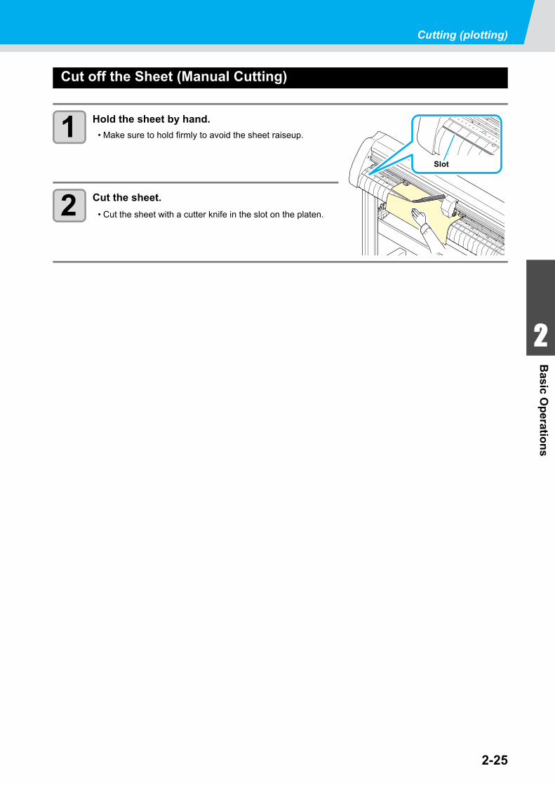
Cut off the Sheet (Manual Cutting)
1 Hold the sheet by hand.
• Make sure to hold firmly to avoid the sheet raiseup.
2 Cut the sheet.
• Cut the sheet with a cutter knife in the slot on the platen.
Slot
2-26
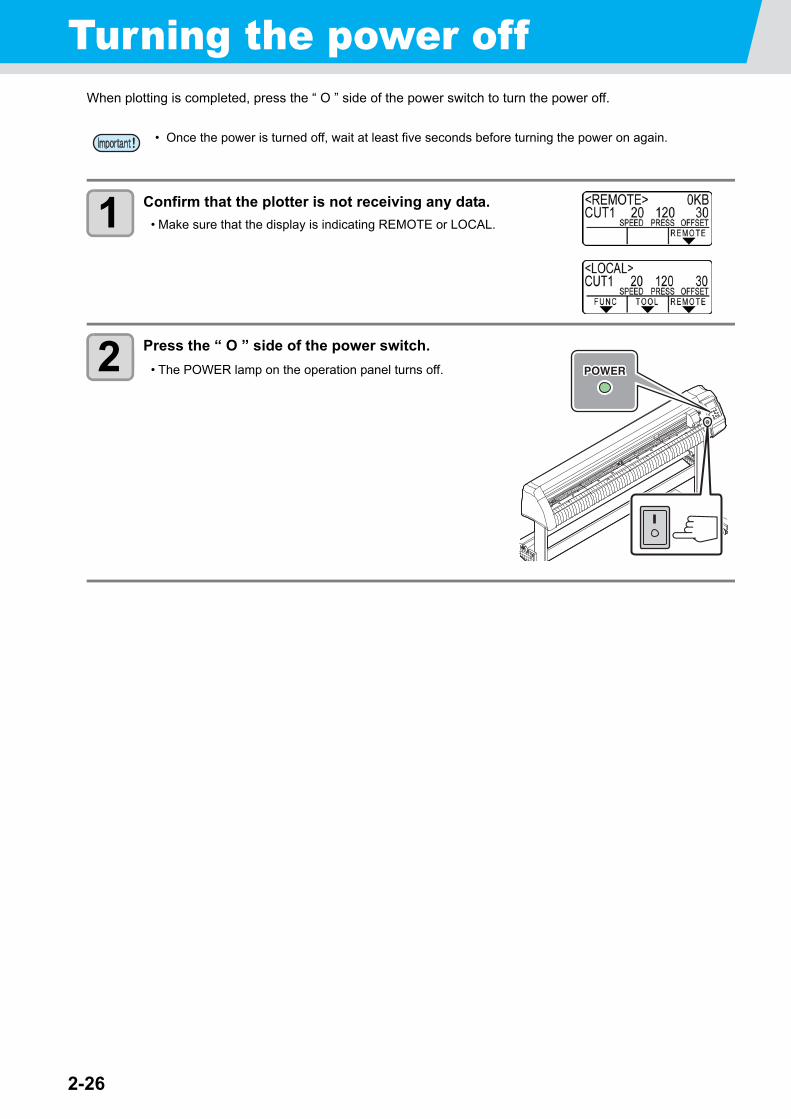
Turning the power offWhen plotting is completed, press the “ O ” side of the power switch to turn the power off.
1 Confirm that the plotter is not receiving any data.
• Make sure that the display is indicating REMOTE or LOCAL.
2 Press the “ O ” side of the power switch.
• The POWER lamp on the operation panel turns off.
• Once the power is turned off, wait at least five seconds before turning the power on again.
This chapter describes the setting procedures of each functions,and how to operate the plotter usefully.
Functions in the Jog Mode ................... 3-2Setting the origin .................................... 3-2Two-point axis alignment ........................ 3-3Cutting area ............................................ 3-4Digitization operation .............................. 3-5
Set the distance compensation............ 3-6Perform Multiple Cuttings..................... 3-9Cut Out Data with Registration Mark . 3-11
The Flow of Cutting out the Registered Data ............................. 3-11Enter the registration mark detection mode ..................................... 3-11Precautions in inputting data with registration marks ................................. 3-12Set for Detecting the Registration Marks . 3-16Method of detecting registration marks 3-21Confirm the following when failed in cutting correctly. ............................................... 3-29
Expand the cutting (plotting) area ..... 3-35Set the EXPANDS function to ON. ....... 3-35
Switch the cutting (plotting) direction 3-37The Setting of ROTATION. .................. 3-37
Perform DIVISION cut.......................... 3-39Set the Y direction (width direction) DIVISION cut ........................................ 3-39Set the X direction (feeding direction) DIVISION cut ........................................ 3-41Cut Data via DIVISION CUT. ............... 3-43
Change the cutting (plotting) order ... 3-44Set SORTING . .....................................3-44Sorting sequence ..................................3-46
Other Useful Functions ....................... 3-47Feed the paper .....................................3-47HOLD ....................................................3-48DATA CLEAR - Discontinue Plotting - 3-48Perform SAMPLE CUT to Find out the Cause of Cutting Error. ....................................3-49Output the Setting List ..........................3-50Output the received data by the ASCII code [ASCII DUMP] .......................................3-51Set the configurations with a computer .3-52Make the media without uncut area ......3-54Select the number of pinch roller to use ..3-56Setting the FEED OFFSET ...................3-57Setting the FEED SPEED .....................3-58Setting the PRE FEED ..........................3-59Set the network .....................................3-61Setting event mail function ....................3-63
Miscellaneous Settings ....................... 3-74Switch the display language .................3-74Switch the User .....................................3-75Other Convenient Settings ....................3-76Copy the set value from the other user setting. ...................3-84Reset the setting values to the initial state. ..................................3-85
CHAPTER 3
Useful Function
3-2
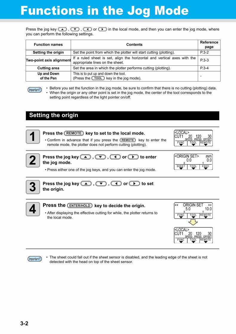
Functions in the Jog ModePress the jog key , , or in the local mode, and then you can enter the jog mode, whereyou can perform the following settings.
Setting the origin
1 Press the key to set to the local mode.
• Confirm in advance that if you press the key to enter theremote mode, the plotter does not perform cutting (plotting).
2 Press the jog key , , or to enter the jog mode.
• Press either one of the jog keys, and you can enter the jog mode.
3 Press the jog key , , or to set the origin.
4 Press the key to decide the origin.
• After displaying the effective cutting for while, the plotter returns tothe local mode.
Function names ContentsReference
page
Setting the origin Set the point from which the plotter will start cutting (plotting). P.3-2
Two-point axis alignmentIf a ruled sheet is set, align the horizontal and vertical axes with theappropriate lines on the sheet.
P.3-3
Cutting area Set the area in which the plotter performs cutting (plotting). P.3-4
Up and Down of the Pen
This is to put up and down the tool. (Press the key in the jog mode).
-
• Before you set the function in the jog mode, be sure to confirm that there is no cutting (plotting) data.• When the origin or any other point is set in the jog mode, the center of the tool corresponds to the
setting point regardless of the light pointer on/off.
• The sheet could fall out if the sheet sensor is disabled, and the leading edge of the sheet is not detected with the head on top of the sheet sensor.
TOOL
REMOTE
REMOTE
ENTER/HOLD
3-3
1
1
3
Usefu
l Fu
nctio
n
5
6
Functions in the Jog Mode
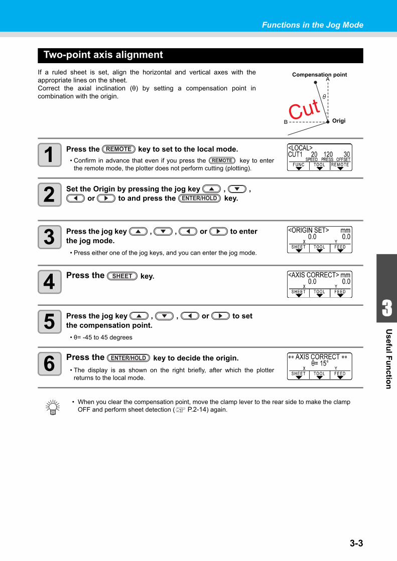
Two-point axis alignment
If a ruled sheet is set, align the horizontal and vertical axes with theappropriate lines on the sheet.Correct the axial inclination (θ) by setting a compensation point incombination with the origin.
1 Press the key to set to the local mode.
• Confirm in advance that even if you press the key to enterthe remote mode, the plotter does not perform cutting (plotting).
2 Set the Origin by pressing the jog key , , or to and press the key.
3 Press the jog key , , or to enter the jog mode.
• Press either one of the jog keys, and you can enter the jog mode.
4 Press the key.
5 Press the jog key , , or to set the compensation point.
• θ= -45 to 45 degrees
6 Press the key to decide the origin.
• The display is as shown on the right briefly, after which the plotterreturns to the local mode.
• When you clear the compensation point, move the clamp lever to the rear side to make the clamp OFF and perform sheet detection ( P.2-14) again.
Origi
Compensation point
REMOTE
REMOTE
ENTER/HOLD
SHEET
ENTER/HOLD

3-4
Cutting area
Set the area in which the plotter performs cutting (plotting).The area that has a diagonal line extending from the originto a given UL (upper left) point is the available cutting area.The cutting area setting will be cleared by performing sheetdetection again.
1 Press the key to set to the local mode.
• Confirm in advance that even if you press the key to enterthe remote mode, the plotter does not perform cutting (plotting).
2 Press the jog key , , or to enter the jog mode.
• Press either one of the jog keys, and you can enter the jog mode.
3 Press the key.
4 Press the jog key , , or to set the point UL.
5 Press the key to decide the point UL.
• The display is as shown on the right briefly, after which the plotterreturns to the local mode.
• Be sure to set the upper left point in the area located in the normal direction from the origin.• Be sure to set the origin in the cutting area. If the origin is located outside the cutting area, the plotter
will go into an error state.
Point UL
Origin
Available cuttingarea
REMOTE
REMOTE
FEED
ENTER/HOLD
3-5
1
1
3
Usefu
l Fu
nctio
n
5
6
Functions in the Jog Mode
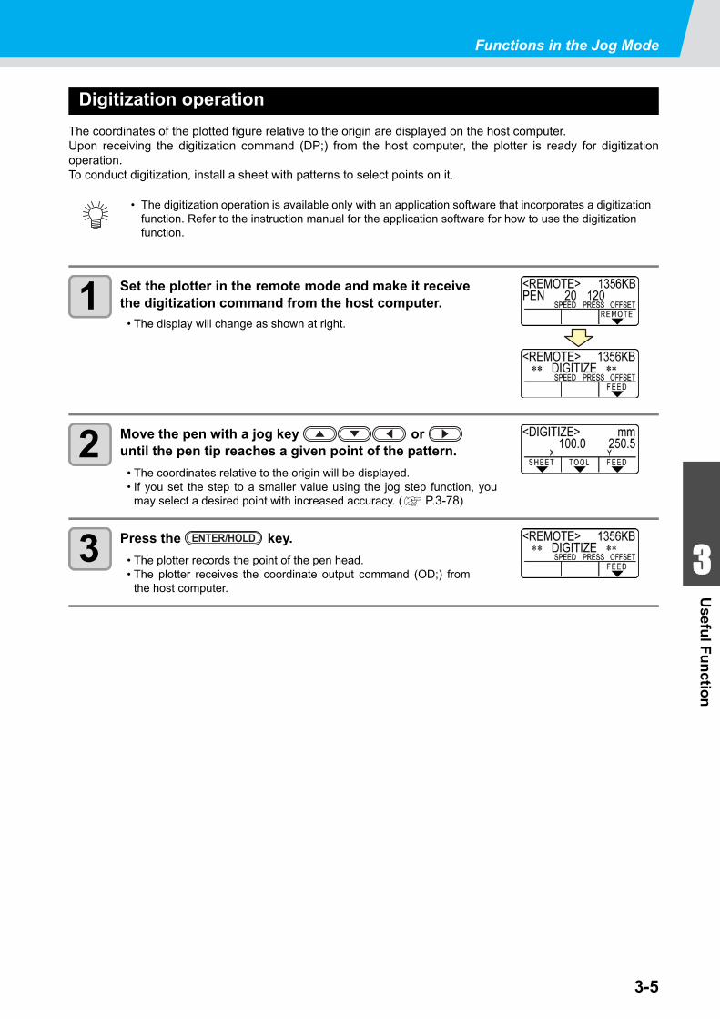
Digitization operation
The coordinates of the plotted figure relative to the origin are displayed on the host computer.Upon receiving the digitization command (DP;) from the host computer, the plotter is ready for digitizationoperation.To conduct digitization, install a sheet with patterns to select points on it.
1 Set the plotter in the remote mode and make it receivethe digitization command from the host computer.
• The display will change as shown at right.
2 Move the pen with a jog key or until the pen tip reaches a given point of the pattern.
• The coordinates relative to the origin will be displayed.• If you set the step to a smaller value using the jog step function, you
may select a desired point with increased accuracy. ( P.3-78)
3 Press the key.
• The plotter records the point of the pen head.• The plotter receives the coordinate output command (OD;) from
the host computer.
• The digitization operation is available only with an application software that incorporates a digitization function. Refer to the instruction manual for the application software for how to use the digitization function.
ENTER/HOLD
3-6
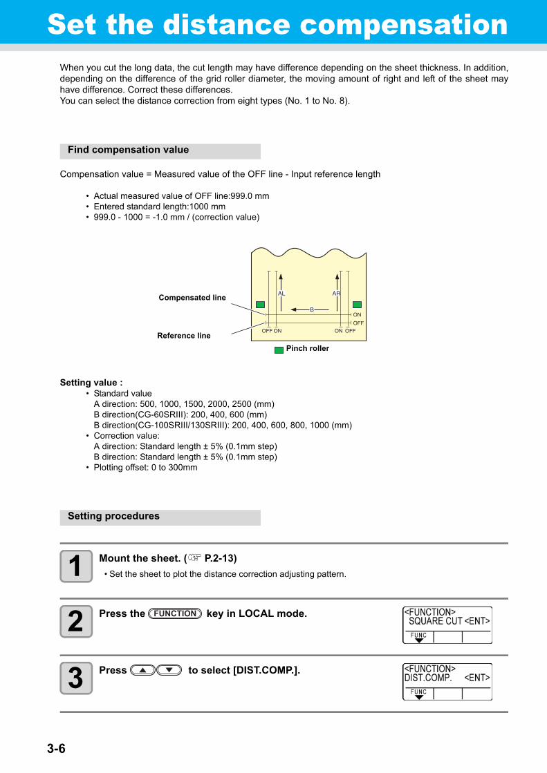
Set the distance compensationWhen you cut the long data, the cut length may have difference depending on the sheet thickness. In addition,depending on the difference of the grid roller diameter, the moving amount of right and left of the sheet mayhave difference. Correct these differences.You can select the distance correction from eight types (No. 1 to No. 8).
Find compensation value
Compensation value = Measured value of the OFF line - Input reference length
• Actual measured value of OFF line:999.0 mm• Entered standard length:1000 mm• 999.0 - 1000 = -1.0 mm / (correction value)
Setting value :• Standard value
A direction: 500, 1000, 1500, 2000, 2500 (mm)B direction(CG-60SRIII): 200, 400, 600 (mm)B direction(CG-100SRIII/130SRIII): 200, 400, 600, 800, 1000 (mm)
• Correction value:A direction: Standard length ± 5% (0.1mm step)B direction: Standard length ± 5% (0.1mm step)
• Plotting offset: 0 to 300mm
Setting procedures
1 Mount the sheet. ( P.2-13)
• Set the sheet to plot the distance correction adjusting pattern.
2 Press the key in LOCAL mode.
3 Press to select [DIST.COMP.].
Compensated line
Reference line
Pinch roller
3-7
1
1
3
Usefu
l Fu
nctio
n
5
6
Set the distance compensation
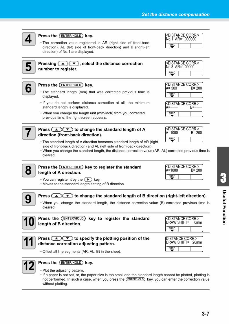
4 Press the key.
• The correction value registered in AR (right side of front-backdirection), AL (left side of front-back direction) and B (right-leftdirection) of No.1 are displayed.
5 Pressing , select the distance correction number to register.
6 Press the key.
• The standard length (mm) that was corrected previous time isdisplayed.
• If you do not perform distance correction at all, the minimumstandard length is displayed.
• When you change the length unit (mm/inch) from you corrected previous time, the right screen appears.
7 Press to change the standard length of A direction (front-back direction).
• The standard length of A direction becomes standard length of AR (rightside of front-back direction) and AL (left side of front-back direction).
• When you change the standard length, the distance correction value (AR, AL) corrected previous time iscleared.
8 Press the key to register the standard length of A direction.
• You can register it by the key.• Moves to the standard length setting of B direction.
9 Press to change the standard length of B direction (right-left direction).
• When you change the standard length, the distance correction value (B) corrected previous time iscleared.
10 Press the key to register the standardlength of B direction.
11 Press to specify the plotting position of thedistance correction adjusting pattern.
• Offset all line segments (AR, AL, B) in the sheet.
12 Press the key.
• Plot the adjusting pattern.• If a paper is not set, or, the paper size is too small and the standard length cannot be plotted, plotting is
not performed. In such a case, when you press the key, you can enter the correction valuewithout plotting.
ENTER/HOLD
ENTER/HOLD
ENTER/HOLD
ENTER/HOLD
ENTER/HOLD
ENTER/HOLD
3-8
Set the distance compensation
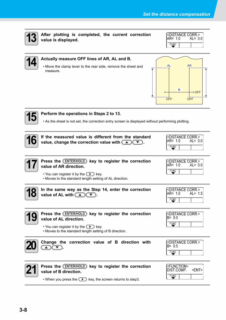
13 After plotting is completed, the current correctionvalue is displayed.
14 Actually measure OFF lines of AR, AL and B.
• Move the clamp lever to the rear side, remove the sheet andmeasure.
15 Perform the operations in Steps 2 to 13.
• As the sheet is not set, the correction entry screen is displayed without performing plotting.
16 If the measured value is different from the standardvalue, change the correction value with .
17 Press the key to register the correctionvalue of AR direction.
• You can register it by the key.• Moves to the standard length setting of AL direction.
18 In the same way as the Step 14, enter the correctionvalue of AL with .
19 Press the key to register the correctionvalue of AL direction.
• You can register it by the key.• Moves to the standard length setting of B direction.
20 Change the correction value of B direction with.
21 Press the key to register the correctionvalue of B direction.
• When you press the key, the screen returns to step3.
ENTER/HOLD
ENTER/HOLD
ENTER/HOLD
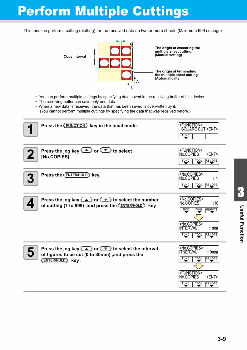
3-9
1
1
3
Usefu
l Fu
nctio
n
5
6
Perform Multiple CuttingsThis function performs cutting (plotting) for the received data on two or more sheets.(Maximum 999 cuttings)
• You can perform multiple cuttings by specifying data saved in the receiving buffer of this device.• The receiving buffer can save only one data.• When a new data is received, the data that has been saved is overwritten by it.
(You cannot perform multiple cuttings by specifying the data that was received before.)
1 Press the key in the local mode.
2 Press the jog key or to select [No.COPIES].
3 Press the key.
4 Press the jog key or to select the number of cutting (1 to 999) ,and press the key .
5 Press the jog key or to select the interval of figures to be cut (0 to 30mm) ,and press the
key .
Copy interval
The origin at executing the multiple sheet cutting.(Manual setting)
The origin at terminating the multiple sheet cutting(Automatically
FUNCTION
ENTER/HOLD
ENTER/HOLD
ENTER/HOLD
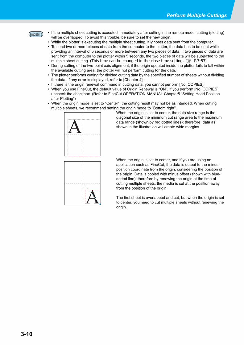
3-10
Perform Multiple Cuttings
• If the multiple sheet cutting is executed immediately after cutting in the remote mode, cutting (plotting) will be overlapped. To avoid this trouble, be sure to set the new origin.
• While the plotter is executing the multiple sheet cutting, it ignores data sent from the computer.• To send two or more pieces of data from the computer to the plotter, the data has to be sent while
providing an interval of 5 seconds or more between any two pieces of data. If two pieces of data are sent from the computer to the plotter within 5 seconds, the two pieces of data will be subjected to the multiple sheet cutting. (This time can be changed in the close time setting. P.3-53)
• During setting of the two-point axis alignment, if the origin updated inside the plotter fails to fall within the available cutting area, the plotter will not perform cutting for the data.
• The plotter performs cutting for divided cutting data by the specified number of sheets without dividing the data. If any error is displayed, refer to [Chapter 4] .
• If there is the origin renewal command in cutting data, you cannot perform [No. COPIES].• When you use FineCut, the default value of Origin Renewal is “ON”. If you perform [No. COPIES],
uncheck the checkbox. (Refer to FineCut OPERATION MANUAL Chapter5 “Setting Head Position after Plotting”)
• When the origin mode is set to "Center", the cutting result may not be as intended. When cutting multiple sheets, we recommend setting the origin mode to "Bottom right".
When the origin is set to center, the data size range is the diagonal size of the minimum cut range area to the maximum data range (shown by red dotted lines); therefore, data as shown in the illustration will create wide margins.
When the origin is set to center, and if you are using an application such as FineCut, the data is output to the minus position coordinate from the origin, considering the position of the origin. Data is copied with minus offset (shown with blue-dotted line); therefore by renewing the origin at the time of cutting multiple sheets, the media is cut at the position away from the position of the origin.
The first sheet is overlapped and cut, but when the origin is set to center, you need to cut multiple sheets without renewing the origin.
A
A
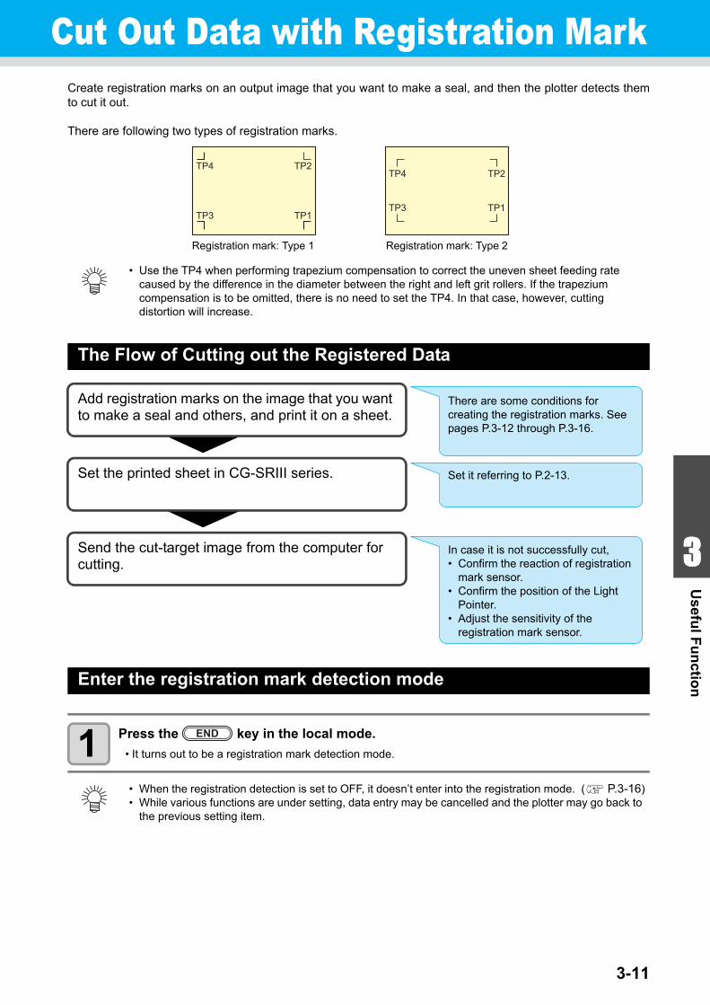
3-11
1
1
3
Usefu
l Fu
nctio
n
5
6
Cut Out Data with Registration MarkCreate registration marks on an output image that you want to make a seal, and then the plotter detects themto cut it out.
There are following two types of registration marks.
The Flow of Cutting out the Registered Data
Enter the registration mark detection mode
1 Press the key in the local mode.
• It turns out to be a registration mark detection mode.
• Use the TP4 when performing trapezium compensation to correct the uneven sheet feeding rate caused by the difference in the diameter between the right and left grit rollers. If the trapezium compensation is to be omitted, there is no need to set the TP4. In that case, however, cutting distortion will increase.
• When the registration detection is set to OFF, it doesn’t enter into the registration mode. ( P.3-16)• While various functions are under setting, data entry may be cancelled and the plotter may go back to
the previous setting item.
TP1
TP2
TP3
TP4
TP1
TP2
TP3
TP4
Registration mark: Type 1 Registration mark: Type 2
Add registration marks on the image that you want to make a seal and others, and print it on a sheet.
Set the printed sheet in CG-SRIII series.
Send the cut-target image from the computer for cutting.
There are some conditions for creating the registration marks. See pages P.3-12 through P.3-16.
Set it referring to P.2-13.
In case it is not successfully cut,• Confirm the reaction of registration
mark sensor. • Confirm the position of the Light
Pointer.• Adjust the sensitivity of the
registration mark sensor.
END
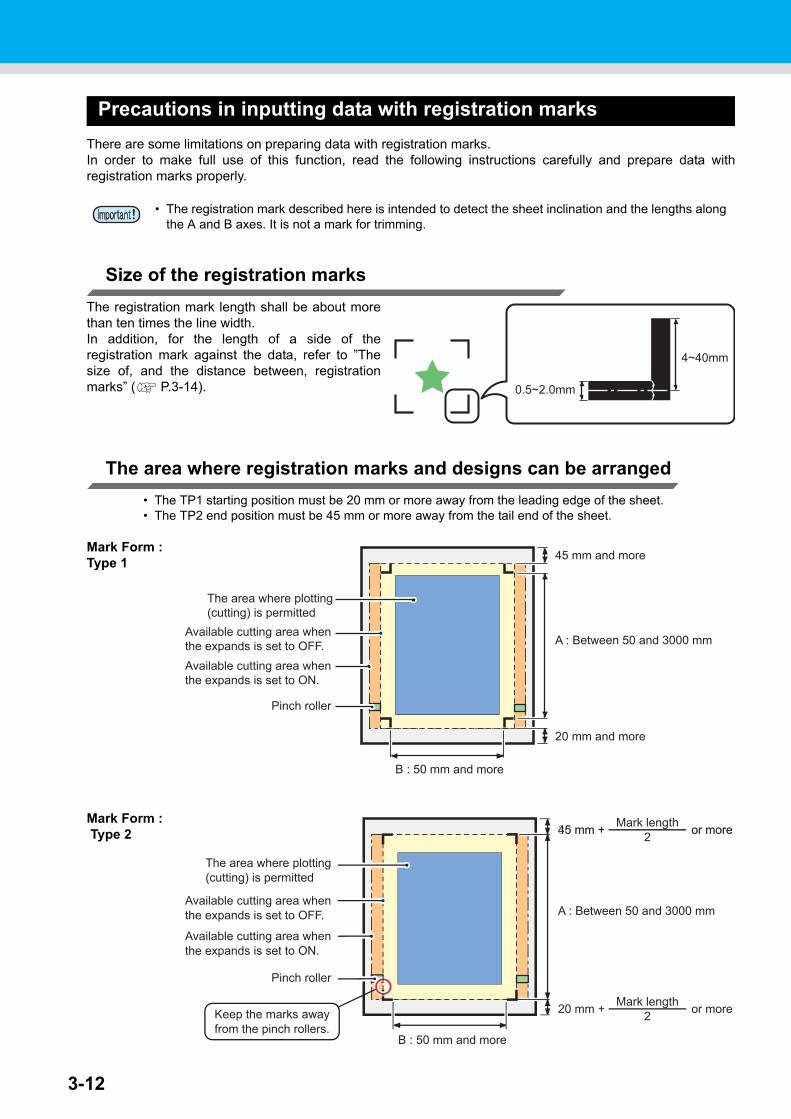
3-12
Precautions in inputting data with registration marks
There are some limitations on preparing data with registration marks.In order to make full use of this function, read the following instructions carefully and prepare data withregistration marks properly.
Size of the registration marks
The registration mark length shall be about morethan ten times the line width.In addition, for the length of a side of theregistration mark against the data, refer to ”Thesize of, and the distance between, registrationmarks” ( P.3-14).
The area where registration marks and designs can be arranged
• The TP1 starting position must be 20 mm or more away from the leading edge of the sheet.• The TP2 end position must be 45 mm or more away from the tail end of the sheet.
Mark Form : Type 1
Mark Form : Type 2
• The registration mark described here is intended to detect the sheet inclination and the lengths along the A and B axes. It is not a mark for trimming.
0.5~2.0mm
4~40mm
The area where plotting(cutting) is permitted
Available cutting area whenthe expands is set to OFF.Available cutting area whenthe expands is set to ON.
Pinch roller
45 mm and more
A : Between 50 and 3000 mm
20 mm and more
B : 50 mm and more
The area where plotting(cutting) is permitted
Available cutting area whenthe expands is set to OFF.
Available cutting area whenthe expands is set to ON.
Pinch roller
30 mm + or more45 mm + or moreMark length2
20 mm + or moreMark length2
A : Between 50 and 3000 mm
B : 50 mm and more
Keep the marks awayfrom the pinch rollers.
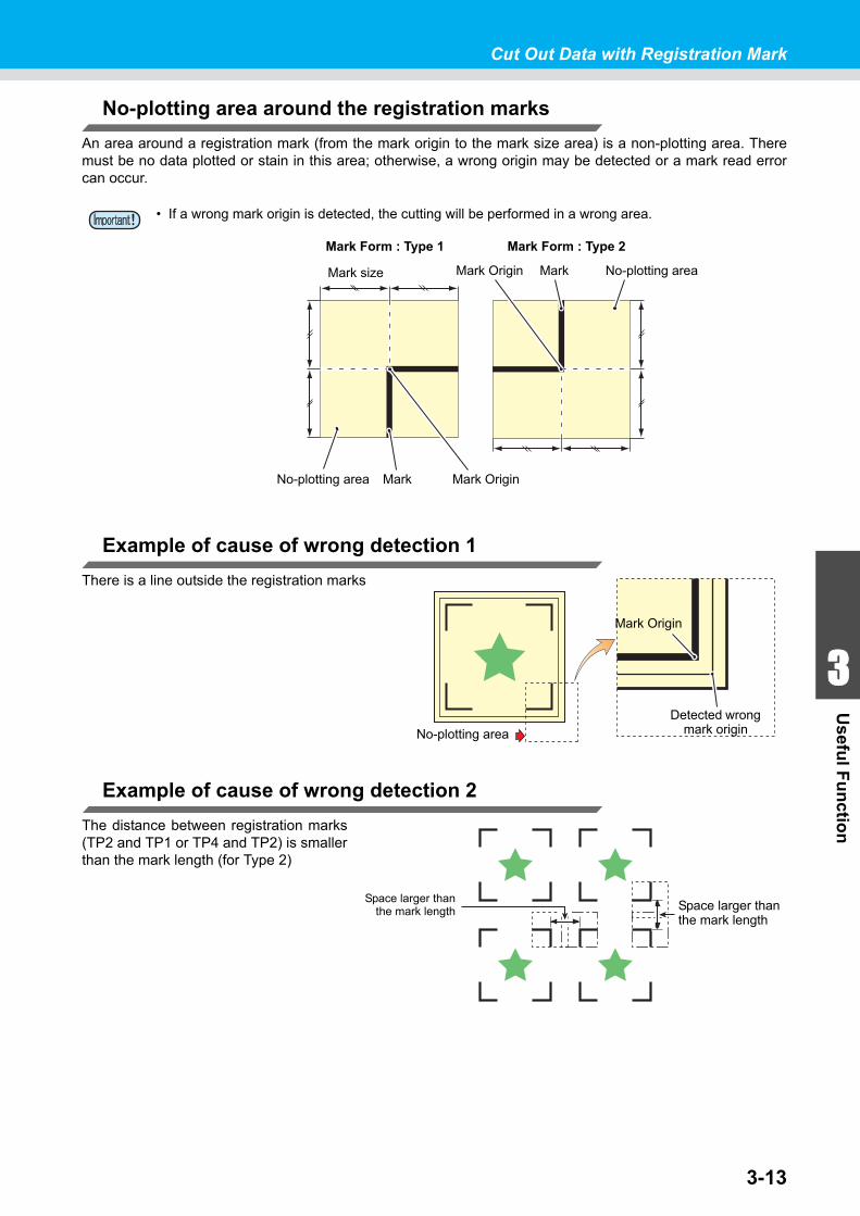
3-13
1
1
3
Usefu
l Fu
nctio
n
5
6
Cut Out Data with Registration Mark
No-plotting area around the registration marks
An area around a registration mark (from the mark origin to the mark size area) is a non-plotting area. Theremust be no data plotted or stain in this area; otherwise, a wrong origin may be detected or a mark read errorcan occur.
Example of cause of wrong detection 1
There is a line outside the registration marks
Example of cause of wrong detection 2
The distance between registration marks(TP2 and TP1 or TP4 and TP2) is smallerthan the mark length (for Type 2)
• If a wrong mark origin is detected, the cutting will be performed in a wrong area.
Mark size
Mark Form : Type 1
No-plotting area Mark Mark Origin
No-plotting areaMarkMark Origin
Mark Form : Type 2
No-plotting area
Mark Origin
Detected wrong mark origin
Space larger thanthe mark length Space larger than
the mark length
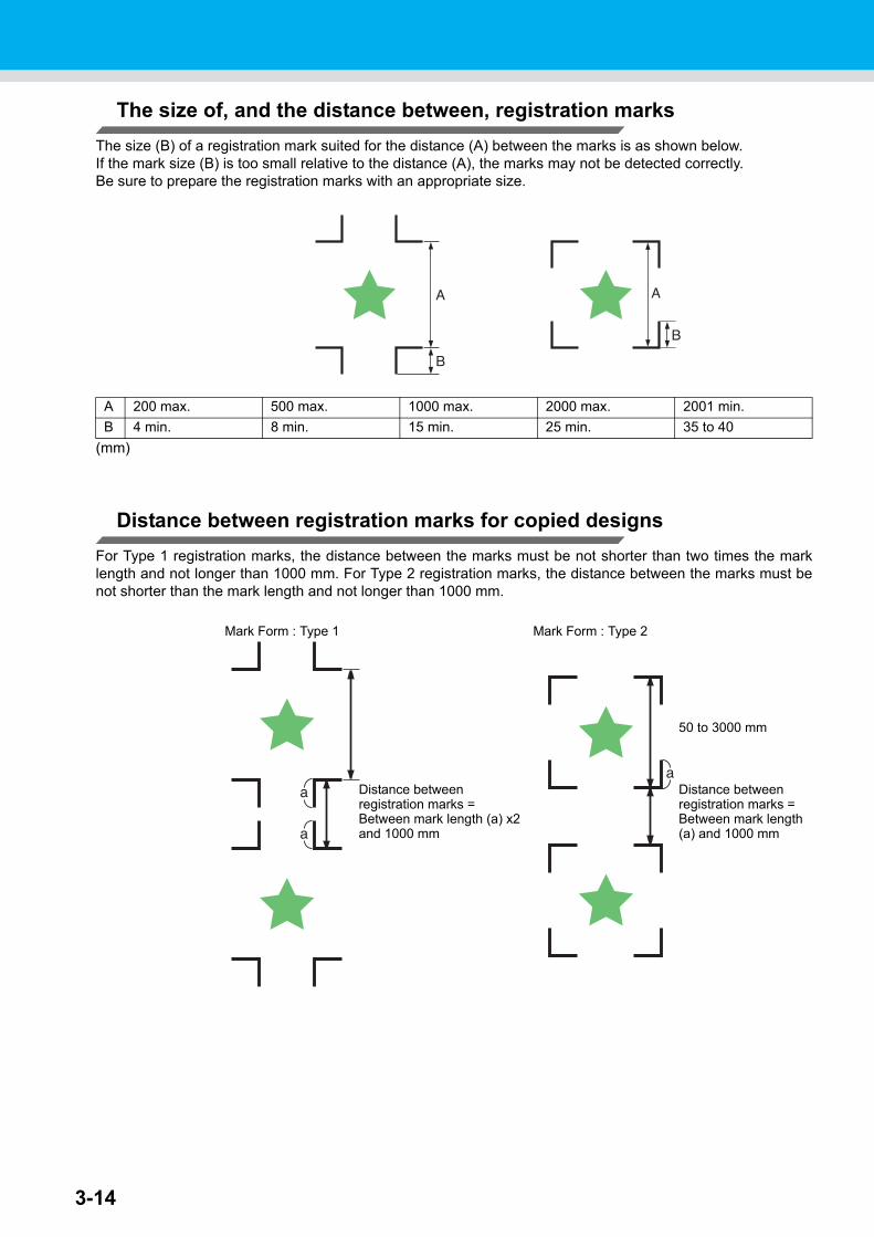
3-14
The size of, and the distance between, registration marks
The size (B) of a registration mark suited for the distance (A) between the marks is as shown below.If the mark size (B) is too small relative to the distance (A), the marks may not be detected correctly.Be sure to prepare the registration marks with an appropriate size.
(mm)
Distance between registration marks for copied designs
For Type 1 registration marks, the distance between the marks must be not shorter than two times the marklength and not longer than 1000 mm. For Type 2 registration marks, the distance between the marks must benot shorter than the mark length and not longer than 1000 mm.
A 200 max. 500 max. 1000 max. 2000 max. 2001 min.
B 4 min. 8 min. 15 min. 25 min. 35 to 40
Mark Form : Type 1 Mark Form : Type 2
Distance betweenregistration marks =Between mark length (a) x2and 1000 mm
50 to 3000 mm
Distance betweenregistration marks =Between mark length(a) and 1000 mm
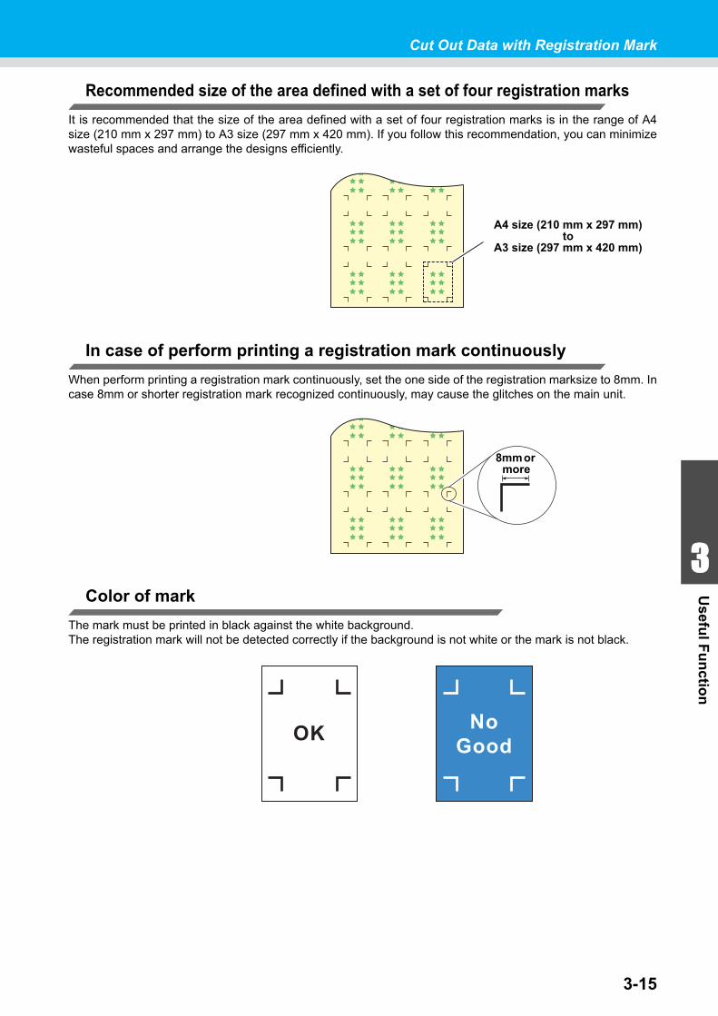
3-15
1
1
3
Usefu
l Fu
nctio
n
5
6
Cut Out Data with Registration Mark
Recommended size of the area defined with a set of four registration marks
It is recommended that the size of the area defined with a set of four registration marks is in the range of A4size (210 mm x 297 mm) to A3 size (297 mm x 420 mm). If you follow this recommendation, you can minimizewasteful spaces and arrange the designs efficiently.
In case of perform printing a registration mark continuously
When perform printing a registration mark continuously, set the one side of the registration marksize to 8mm. Incase 8mm or shorter registration mark recognized continuously, may cause the glitches on the main unit.
Color of mark
The mark must be printed in black against the white background.The registration mark will not be detected correctly if the background is not white or the mark is not black.
A4 size (210 mm x 297 mm)to
A3 size (297 mm x 420 mm)
8mm or more
OK NoGood
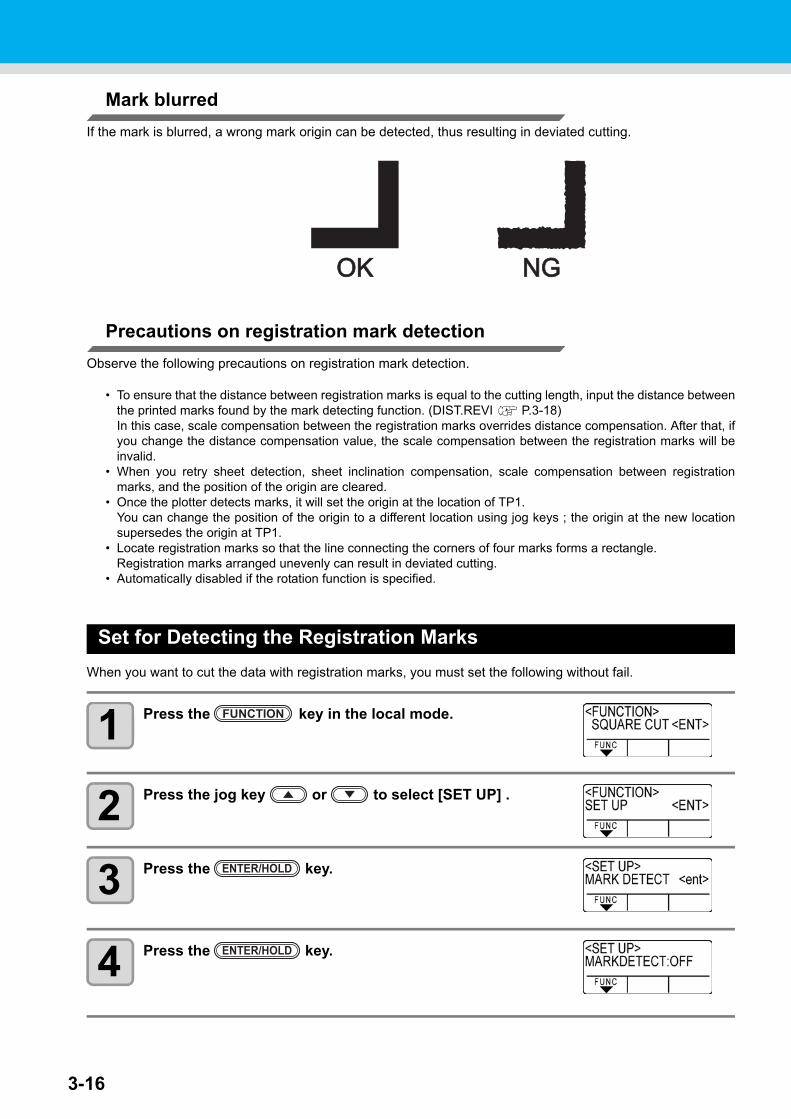
3-16
Mark blurred
If the mark is blurred, a wrong mark origin can be detected, thus resulting in deviated cutting.
Precautions on registration mark detection
Observe the following precautions on registration mark detection.
• To ensure that the distance between registration marks is equal to the cutting length, input the distance betweenthe printed marks found by the mark detecting function. (DIST.REVI P.3-18)In this case, scale compensation between the registration marks overrides distance compensation. After that, ifyou change the distance compensation value, the scale compensation between the registration marks will beinvalid.
• When you retry sheet detection, sheet inclination compensation, scale compensation between registrationmarks, and the position of the origin are cleared.
• Once the plotter detects marks, it will set the origin at the location of TP1.You can change the position of the origin to a different location using jog keys ; the origin at the new locationsupersedes the origin at TP1.
• Locate registration marks so that the line connecting the corners of four marks forms a rectangle.Registration marks arranged unevenly can result in deviated cutting.
• Automatically disabled if the rotation function is specified.
Set for Detecting the Registration Marks
When you want to cut the data with registration marks, you must set the following without fail.
1 Press the key in the local mode.
2 Press the jog key or to select [SET UP] .
3 Press the key.
4 Press the key.
OKOK NGNG
FUNCTION
ENTER/HOLD
ENTER/HOLD
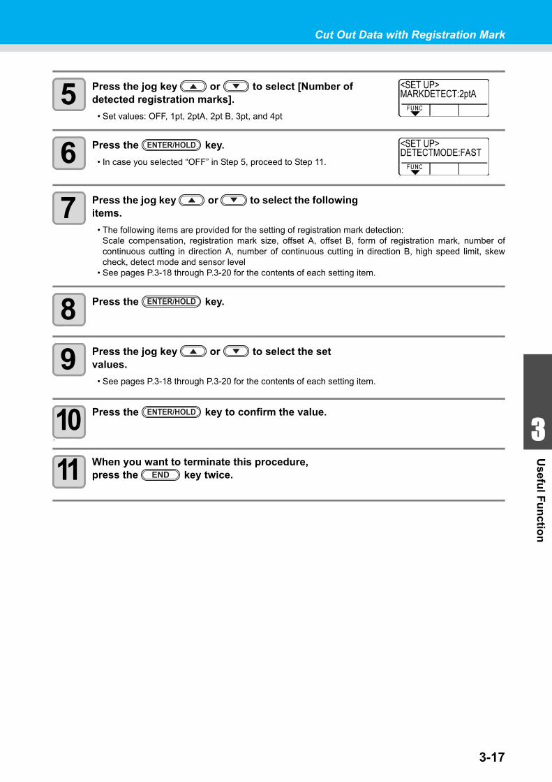
3-17
1
1
3
Usefu
l Fu
nctio
n
5
6
Cut Out Data with Registration Mark
5 Press the jog key or to select [Number of detected registration marks].
• Set values: OFF, 1pt, 2ptA, 2pt B, 3pt, and 4pt
6 Press the key.
• In case you selected “OFF” in Step 5, proceed to Step 11.
7 Press the jog key or to select the following items.
• The following items are provided for the setting of registration mark detection:Scale compensation, registration mark size, offset A, offset B, form of registration mark, number ofcontinuous cutting in direction A, number of continuous cutting in direction B, high speed limit, skewcheck, detect mode and sensor level
• See pages P.3-18 through P.3-20 for the contents of each setting item.
8 Press the key.
9 Press the jog key or to select the set values.
• See pages P.3-18 through P.3-20 for the contents of each setting item.
10 Press the key to confirm the value.
イ
11 When you want to terminate this procedure, press the key twice.
ENTER/HOLD
ENTER/HOLD
ENTER/HOLD
END
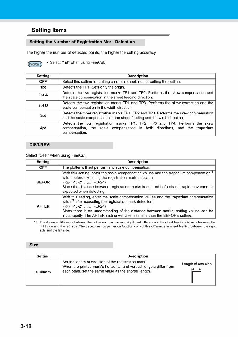
3-18
Setting Items
Setting the Number of Registration Mark Detection
The higher the number of detected points, the higher the cutting accuracy.
DIST.REVI
Select “OFF” when using FineCut.
Size
• Select “1pt” when using FineCut.
Setting Description
OFF Select this setting for cutting a normal sheet, not for cutting the outline.
1pt Detects the TP1. Sets only the origin.
2pt ADetects the two registration marks TP1 and TP2. Performs the skew compensation andthe scale compensation in the sheet feeding direction.
2pt BDetects the two registration marks TP1 and TP3. Performs the skew correction and thescale compensation in the width direction.
3ptDetects the three registration marks TP1, TP2 and TP3. Performs the skew compensationand the scale compensation in the sheet feeding and the width direction.
4ptDetects the four registration marks TP1, TP2, TP3 and TP4. Performs the skewcompensation, the scale compensation in both directions, and the trapeziumcompensation.
Setting Description
OFF The plotter will not perform any scale compensation.
BEFOR
With this setting, enter the scale compensation values and the trapezium compensation*1
value before executing the registration mark detection. ( P.3-21 , P.3-24)Since the distance between registration marks is entered beforehand, rapid movement isexpected when detecting.
*1. The diameter difference between the grit rollers may cause a significant difference in the sheet feeding distance between theright side and the left side. The trapezium compensation function correct this difference in sheet feeding between the rightside and the left side.
AFTER
With this setting, enter the scale compensation values and the trapezium compensationvalue*1 after executing the registration mark detection. ( P.3-21 , P.3-24)Since there is an understanding of the distance between marks, setting values can beinput rapidly. The AFTER setting will take less time than the BEFORE setting.
Setting Description
4~40mm
Set the length of one side of the registration mark.When the printed mark's horizontal and vertical lengths differ fromeach other, set the same value as the shorter length.
Length of one side
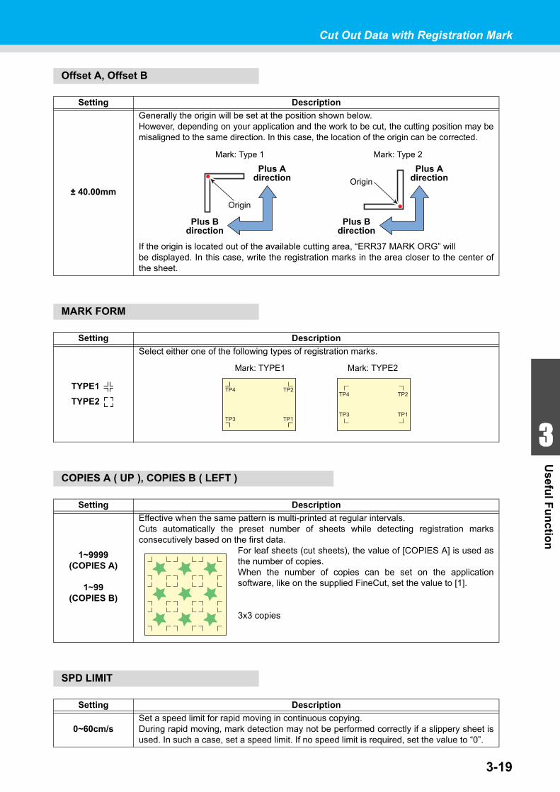
3-19
1
1
3
Usefu
l Fu
nctio
n
5
6
Cut Out Data with Registration Mark
Offset A, Offset B
MARK FORM
COPIES A ( UP ), COPIES B ( LEFT )
SPD LIMIT
Setting Description
± 40.00mm
Generally the origin will be set at the position shown below.However, depending on your application and the work to be cut, the cutting position may bemisaligned to the same direction. In this case, the location of the origin can be corrected.
If the origin is located out of the available cutting area, “ERR37 MARK ORG” willbe displayed. In this case, write the registration marks in the area closer to the center ofthe sheet.
Setting Description
TYPE1
TYPE2
Select either one of the following types of registration marks.
Setting Description
1~9999(COPIES A)
1~99(COPIES B)
Effective when the same pattern is multi-printed at regular intervals.Cuts automatically the preset number of sheets while detecting registration marksconsecutively based on the first data.
For leaf sheets (cut sheets), the value of [COPIES A] is used asthe number of copies.When the number of copies can be set on the applicationsoftware, like on the supplied FineCut, set the value to [1].
3x3 copies
Setting Description
0~60cm/sSet a speed limit for rapid moving in continuous copying.During rapid moving, mark detection may not be performed correctly if a slippery sheet isused. In such a case, set a speed limit. If no speed limit is required, set the value to “0”.
Mark: Type 1 Mark: Type 2
Origin
Origin
Plus Adirection
Plus Adirection
Plus Bdirection
Plus Bdirection
TP1
TP2
TP3
TP4
TP1
TP2
TP3
TP4
Mark: TYPE1 Mark: TYPE2
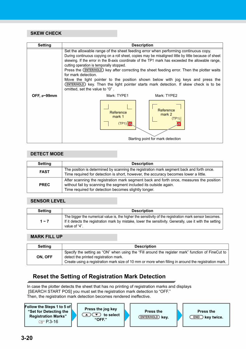
3-20
SKEW CHECK
DETECT MODE
SENSOR LEVEL
MARK FILL UP
Reset the Setting of Registration Mark Detection
In case the plotter detects the sheet that has no printing of registration marks and displays [SEARCH START POS] you must set the registration mark detection to “OFF.”Then, the registration mark detection becomes rendered ineffective.
Setting Description
OFF, 1~99mm
Set the allowable range of the sheet feeding error when performing continuous copy.During continuous copying on a roll sheet, copies may be misaligned little by little because of sheetskewing. If the error in the B-axis coordinate of the TP1 mark has exceeded the allowable range,cutting operation is temporally stopped.Press the key after correcting the sheet feeding error. Then the plotter waitsfor mark detection.Move the light pointer to the position shown below with jog keys and press the
key. Then the light pointer starts mark detection. If skew check is to beomitted, set the value to “0” .
Setting Description
FASTThe position is determined by scanning the registration mark segment back and forth once.Time required for detection is short, however, the accuracy becomes lower a little.
PRECAfter scanning the registration mark segment back and forth once, measures the positionwithout fail by scanning the segment included its outside again.Time required for detection becomes slightly longer.
Setting Description
1 ~ 7The bigger the numerical value is, the higher the sensitivity of the registration mark sensor becomes.If it detects the registration mark by mistake, lower the sensitivity. Generally, use it with the settingvalue of “4”.
Setting Description
ON, OFFSpecify the setting as “ON” when using the “Fill around the register mark” function of FineCut todetect the printed registration mark.Create using a registration mark size of 10 mm or more when filling in around the registration mark.
Follow the Steps 1 to 5 of “Set for Detecting the Registration Marks”
P.3-16
Press the jog key
to select “OFF.”
Press the
key.
Press the
key twice.
ENTER/HOLD
ENTER/HOLD
Mark: TYPE1 Mark: TYPE2
Starting point for mark detection
Referencemark 1
Referencemark 2
ENTER/HOLD END
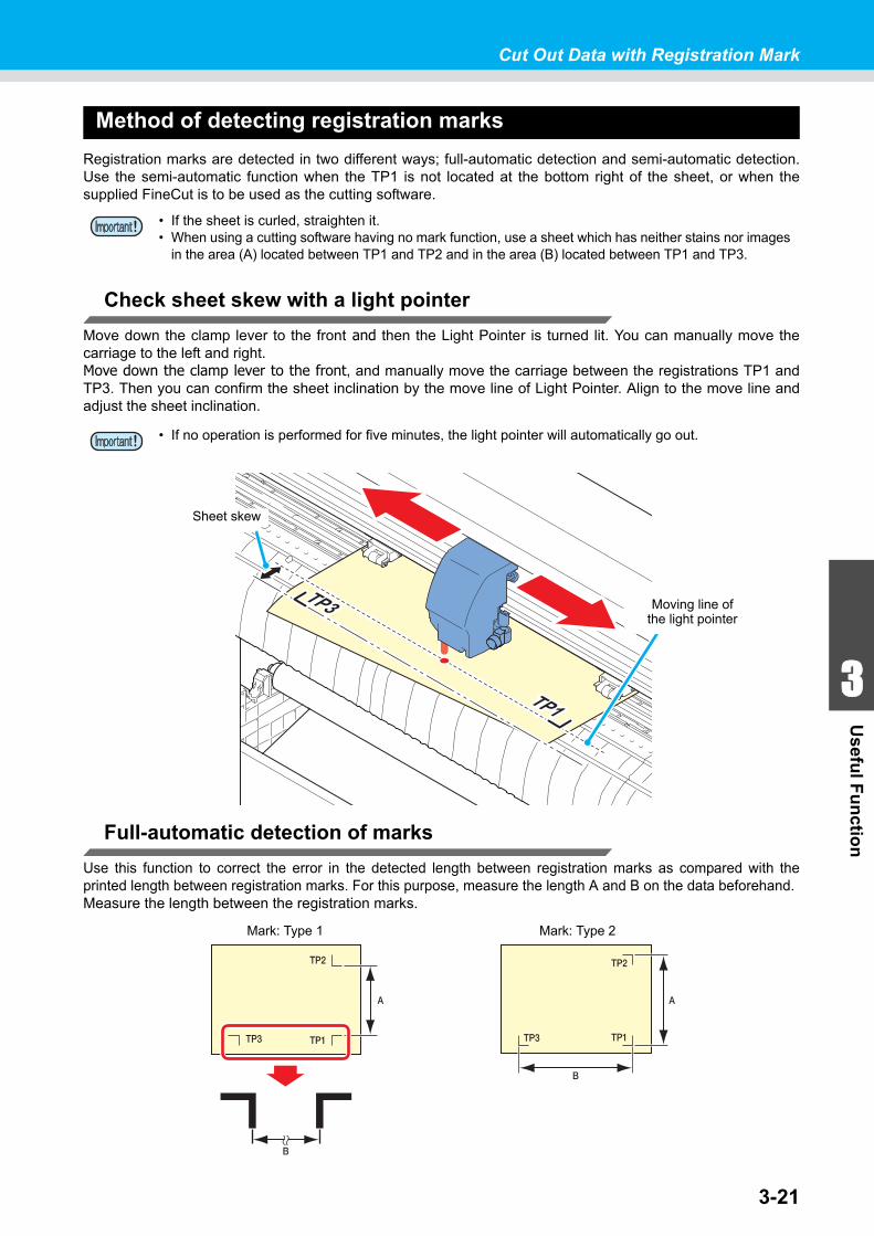
3-21
1
1
3
Usefu
l Fu
nctio
n
5
6
Cut Out Data with Registration Mark
Method of detecting registration marks
Registration marks are detected in two different ways; full-automatic detection and semi-automatic detection.Use the semi-automatic function when the TP1 is not located at the bottom right of the sheet, or when thesupplied FineCut is to be used as the cutting software.
Check sheet skew with a light pointer
Move down the clamp lever to the front and then the Light Pointer is turned lit. You can manually move thecarriage to the left and right.Move down the clamp lever to the front, and manually move the carriage between the registrations TP1 andTP3. Then you can confirm the sheet inclination by the move line of Light Pointer. Align to the move line andadjust the sheet inclination.
Full-automatic detection of marks
Use this function to correct the error in the detected length between registration marks as compared with theprinted length between registration marks. For this purpose, measure the length A and B on the data beforehand.Measure the length between the registration marks.
• If the sheet is curled, straighten it.• When using a cutting software having no mark function, use a sheet which has neither stains nor images
in the area (A) located between TP1 and TP2 and in the area (B) located between TP1 and TP3.
• If no operation is performed for five minutes, the light pointer will automatically go out.
Moving line ofthe light pointer
Sheet skew
Mark: Type 1 Mark: Type 2
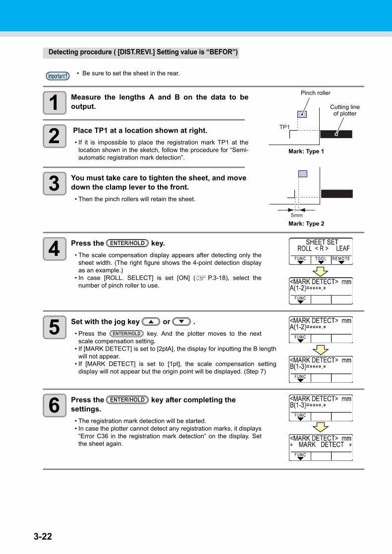
3-22
Detecting procedure ( [DIST.REVI.] Setting value is “BEFOR”)
1 Measure the lengths A and B on the data to beoutput.
2 Place TP1 at a location shown at right.
• If it is impossible to place the registration mark TP1 at thelocation shown in the sketch, follow the procedure for “Semi-automatic registration mark detection”.
3 You must take care to tighten the sheet, and move down the clamp lever to the front.
• Then the pinch rollers will retain the sheet.
4 Press the key.
• The scale compensation display appears after detecting only thesheet width. (The right figure shows the 4-point detection displayas an example.)
• In case [ROLL. SELECT] is set [ON] ( P.3-18), select thenumber of pinch roller to use.
5 Set with the jog key or .
• Press the key. And the plotter moves to the nextscale compensation setting.
• If [MARK DETECT] is set to [2ptA], the display for inputting the B lengthwill not appear.
• If [MARK DETECT] is set to [1pt], the scale compensation settingdisplay will not appear but the origin point will be displayed. (Step 7)
6 Press the key after completing the settings.
• The registration mark detection will be started.• In case the plotter cannot detect any registration marks, it displays
“Error C36 in the registration mark detection” on the display. Setthe sheet again.
• Be sure to set the sheet in the rear.
5mm
Mark: Type 1
Mark: Type 2
Pinch roller
Cutting lineof plotter
ENTER/HOLD
ENTER/HOLD
ENTER/HOLD
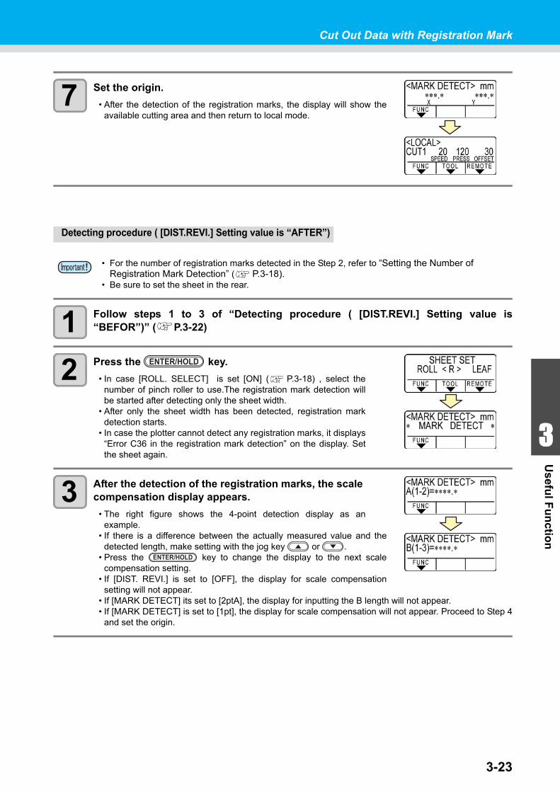
3-23
1
1
3
Usefu
l Fu
nctio
n
5
6
Cut Out Data with Registration Mark
7 Set the origin.
• After the detection of the registration marks, the display will show theavailable cutting area and then return to local mode.
Detecting procedure ( [DIST.REVI.] Setting value is “AFTER”)
1 Follow steps 1 to 3 of “Detecting procedure ( [DIST.REVI.] Setting value is“BEFOR”)” ( P.3-22)
2 Press the key.
• In case [ROLL. SELECT] is set [ON] ( P.3-18) , select thenumber of pinch roller to use.The registration mark detection willbe started after detecting only the sheet width.
• After only the sheet width has been detected, registration markdetection starts.
• In case the plotter cannot detect any registration marks, it displays“Error C36 in the registration mark detection” on the display. Setthe sheet again.
3 After the detection of the registration marks, the scale compensation display appears.
• The right figure shows the 4-point detection display as anexample.
• If there is a difference between the actually measured value and thedetected length, make setting with the jog key or .
• Press the key to change the display to the next scalecompensation setting.
• If [DIST. REVI.] is set to [OFF], the display for scale compensationsetting will not appear.
• If [MARK DETECT] its set to [2ptA], the display for inputting the B length will not appear.• If [MARK DETECT] is set to [1pt], the display for scale compensation will not appear. Proceed to Step 4
and set the origin.
• For the number of registration marks detected in the Step 2, refer to ”Setting the Number of Registration Mark Detection” ( P.3-18).
• Be sure to set the sheet in the rear.
ENTER/HOLD
ENTER/HOLD
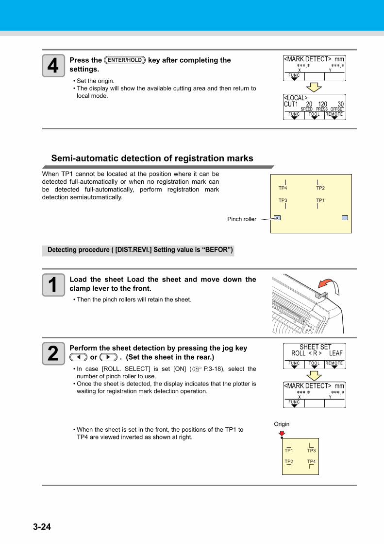
3-24
4 Press the key after completing the settings.
• Set the origin.• The display will show the available cutting area and then return to
local mode.
Semi-automatic detection of registration marks
When TP1 cannot be located at the position where it can bedetected full-automatically or when no registration mark canbe detected full-automatically, perform registration markdetection semiautomatically.
Detecting procedure ( [DIST.REVI.] Setting value is “BEFOR”)
1 Load the sheet Load the sheet and move down theclamp lever to the front.
• Then the pinch rollers will retain the sheet.
2 Perform the sheet detection by pressing the jog key or . (Set the sheet in the rear.)
• In case [ROLL. SELECT] is set [ON] ( P.3-18), select thenumber of pinch roller to use.
• Once the sheet is detected, the display indicates that the plotter iswaiting for registration mark detection operation.
• When the sheet is set in the front, the positions of the TP1 toTP4 are viewed inverted as shown at right.
ENTER/HOLD
Pinch roller
Origin
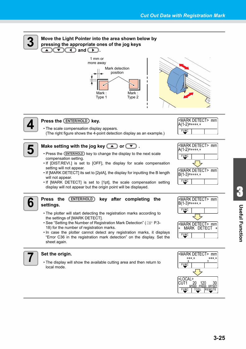
3-25
1
1
3
Usefu
l Fu
nctio
n
5
6
Cut Out Data with Registration Mark
3 Move the Light Pointer into the area shown below by pressing the appropriate ones of the jog keys
and .
4 Press the key.
• The scale compensation display appears.(The right figure shows the 4-point detection display as an example.)
5 Make setting with the jog key or .
• Press the key to change the display to the next scalecompensation setting.
• If [DIST.REVI.] is set to [OFF], the display for scale compensationsetting will not appear.
• If [MARK DETECT] its set to [2ptA], the display for inputting the B lengthwill not appear.
• If [MARK DETECT] is set to [1pt], the scale compensation settingdisplay will not appear but the origin point will be displayed.
6 Press the key after completing thesettings.
• The plotter will start detecting the registration marks according tothe settings of [MARK DETECT].
• See “Setting the Number of Registration Mark Detection” ( P.3-18) for the number of registration marks.
• In case the plotter cannot detect any registration marks, it displays“Error C36 in the registration mark detection” on the display. Set thesheet again.
7 Set the origin.
• The display will show the available cutting area and then return tolocal mode.
1 mm ormore away
Mark detectionposition
Mark : Type 1
Mark : Type 2
ENTER/HOLD
ENTER/HOLD
ENTER/HOLD
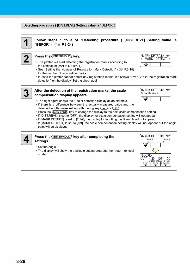
3-26
Detecting procedure ( [DIST.REVI.] Setting value is “BEFOR”)
1 Follow steps 1 to 3 of “Detecting procedure ( [DIST.REVI.] Setting value is“BEFOR”)” ( P.3-24)
2 Press the key.
• The plotter will start detecting the registration marks according tothe settings of [MARK DETECT].
• See “Setting the Number of Registration Mark Detection” ( P.3-18)for the number of registration marks.
• In case the plotter cannot detect any registration marks, it displays “Error C36 in the registration markdetection” on the display. Set the sheet again.
3 After the detection of the registration marks, the scale compensation display appears.
• The right figure shows the 4-point detection display as an example.• If there is a difference between the actually measured value and the
detected length, make setting with the jog key or .• Press the key to change the display to the next scale compensation setting.• If [DIST.REVI.] is set to [OFF], the display for scale compensation setting will not appear.• If [MARK DETECT] is set to [2ptA], the display for inputting the B length will not appear.• If [MARK DETECT] is set to [1pt], the scale compensation setting display will not appear but the origin
point will be displayed.
4 Press the key after completing the settings.
• Set the origin.• The display will show the available cutting area and then return to local
mode.
ENTER/HOLD
ENTER/HOLD
ENTER/HOLD
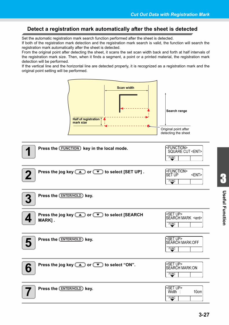
3-27
1
1
3
Usefu
l Fu
nctio
n
5
6
Cut Out Data with Registration Mark
Detect a registration mark automatically after the sheet is detected
Set the automatic registration mark search function performed after the sheet is detected.If both of the registration mark detection and the registration mark search is valid, the function will search theregistration mark automatically after the sheet is detected.From the original point after detecting the sheet, it scans the set scan width back and forth at half intervals ofthe registration mark size. Then, when it finds a segment, a point or a printed material, the registration markdetection will be performed.If the vertical line and the horizontal line are detected properly, it is recognized as a registration mark and theoriginal point setting will be performed.
1 Press the key in the local mode.
2 Press the jog key or to select [SET UP] .
3 Press the key.
4 Press the jog key or to select [SEARCH MARK] .
5 Press the key.
6 Press the jog key or to select “ON”.
7 Press the key.
Scan width
Half of registration mark size
Original point after detecting the sheet
Search range
FUNCTION
ENTER/HOLD
ENTER/HOLD
ENTER/HOLD
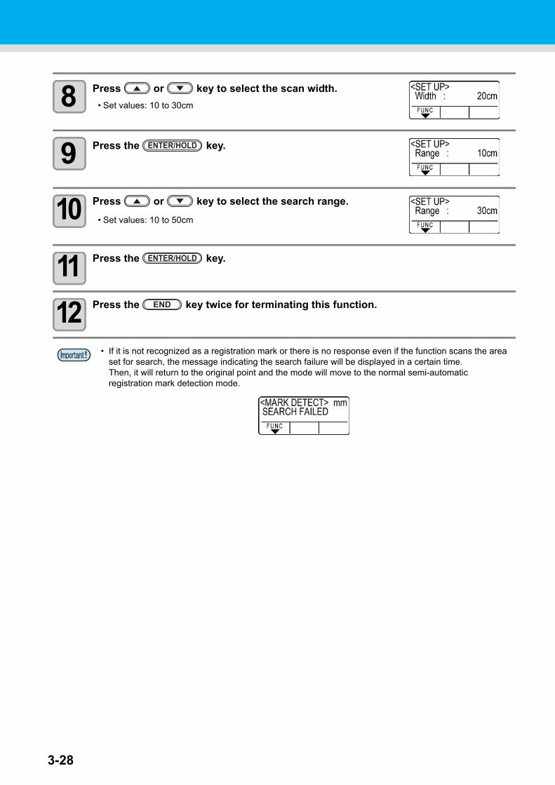
3-28
8 Press or key to select the scan width.
• Set values: 10 to 30cm
9 Press the key.
10 Press or key to select the search range.
• Set values: 10 to 50cm
11 Press the key.
12 Press the key twice for terminating this function.
• If it is not recognized as a registration mark or there is no response even if the function scans the area set for search, the message indicating the search failure will be displayed in a certain time.Then, it will return to the original point and the mode will move to the normal semi-automatic registration mark detection mode.
ENTER/HOLD
ENTER/HOLD
END
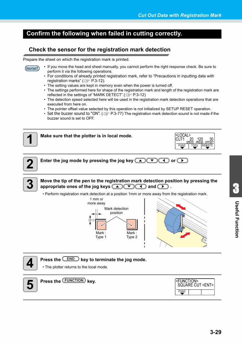
3-29
1
1
3
Usefu
l Fu
nctio
n
5
6
Cut Out Data with Registration Mark
Confirm the following when failed in cutting correctly.
Check the sensor for the registration mark detection
Prepare the sheet on which the registration mark is printed.
1 Make sure that the plotter is in local mode.
2 Enter the jog mode by pressing the jog key or
3 Move the tip of the pen to the registration mark detection position by pressing the appropriate ones of the jog keys and .
• Perform registration mark detection at a position 1mm or more away from the registration mark.
4 Press the key to terminate the jog mode.
• The plotter returns to the local mode.
5 Press the key.
• If you move the head and sheet manually, you cannot perform the right response check. Be sure to perform it via the following operations.
• For conditions of already printed registration mark, refer to “Precautions in inputting data with registration marks” ( P.3-12).
• The setting values are kept in memory even when the power is turned off.• The settings performed here for shape of the registration mark and length of the registration mark are
reflected in the settings of “MARK DETECT”.( P.3-12) • The detection speed selected here will be used in the registration mark detection operations that are
executed from here on.• The pointer offset value selected by this operation is not initialized by SETUP RESET operation.• Set the buzzer sound to “ON”. ( P.3-77) The registration mark detection sound is not made if the
buzzer sound is set to OFF.
1 mm ormore away
Mark detectionposition
Mark : Type 1
Mark : Type 2
END
FUNCTION
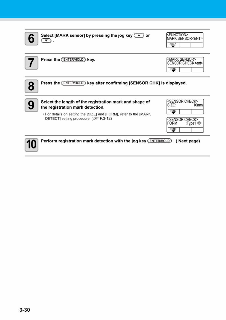
3-30
6 Select [MARK sensor] by pressing the jog key or .
7 Press the key.
8 Press the key after confirming [SENSOR CHK] is displayed.
9 Select the length of the registration mark and shape of the registration mark detection.
• For details on setting the [SIZE] and [FORM], refer to the [MARKDETECT] setting procedure. ( P.3-12)
10 Perform registration mark detection with the jog key . ( Next page)
ENTER/HOLD
ENTER/HOLD
ENTER/HOLD
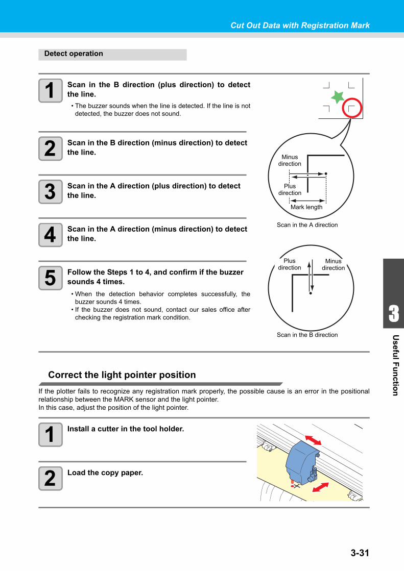
3-31
1
1
3
Usefu
l Fu
nctio
n
5
6
Cut Out Data with Registration Mark
Detect operation
1 Scan in the B direction (plus direction) to detectthe line.
• The buzzer sounds when the line is detected. If the line is notdetected, the buzzer does not sound.
2 Scan in the B direction (minus direction) to detect the line.
3 Scan in the A direction (plus direction) to detect the line.
4 Scan in the A direction (minus direction) to detect the line.
5 Follow the Steps 1 to 4, and confirm if the buzzer sounds 4 times.
• When the detection behavior completes successfully, thebuzzer sounds 4 times.
• If the buzzer does not sound, contact our sales office afterchecking the registration mark condition.
Correct the light pointer position
If the plotter fails to recognize any registration mark properly, the possible cause is an error in the positionalrelationship between the MARK sensor and the light pointer.In this case, adjust the position of the light pointer.
1 Install a cutter in the tool holder.
2 Load the copy paper.
Minusdirection
Plusdirection
Mark length
Scan in the A direction
Scan in the B direction
Minusdirection
Plusdirection
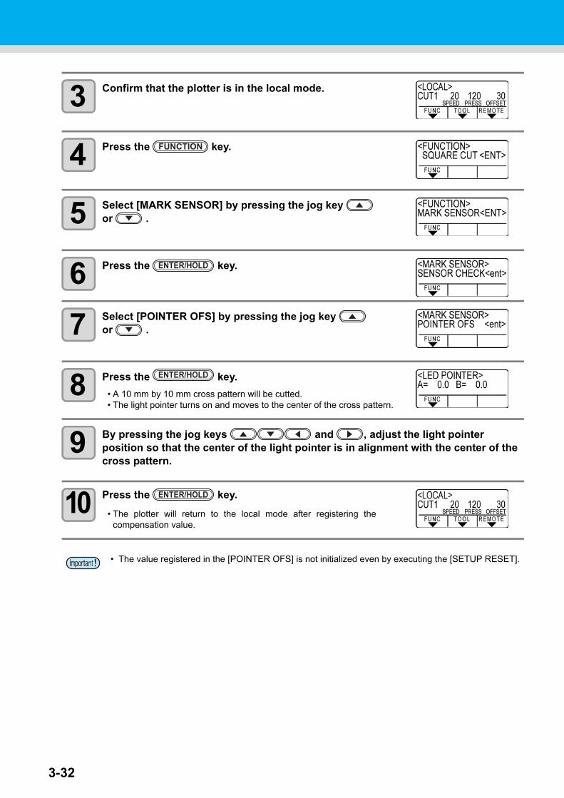
3-32
3 Confirm that the plotter is in the local mode.
4 Press the key.
5 Select [MARK SENSOR] by pressing the jog key or .
6 Press the key.
7 Select [POINTER OFS] by pressing the jog key or .
8 Press the key.
• A 10 mm by 10 mm cross pattern will be cutted.• The light pointer turns on and moves to the center of the cross pattern.
9 By pressing the jog keys and , adjust the light pointer position so that the center of the light pointer is in alignment with the center of the cross pattern.
10 Press the key.
• The plotter will return to the local mode after registering thecompensation value.
• The value registered in the [POINTER OFS] is not initialized even by executing the [SETUP RESET].
FUNCTION
ENTER/HOLD
ENTER/HOLD
ENTER/HOLD
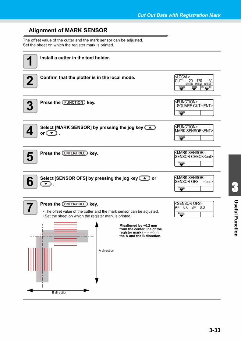
3-33
1
1
3
Usefu
l Fu
nctio
n
5
6
Cut Out Data with Registration Mark
Alignment of MARK SENSOR
The offset value of the cutter and the mark sensor can be adjusted.Set the sheet on which the register mark is printed.
1 Install a cutter in the tool holder.
2 Confirm that the plotter is in the local mode.
3 Press the key.
4 Select [MARK SENSOR] by pressing the jog key or .
5 Press the key.
6 Select [SENSOR OFS] by pressing the jog key or .
7 Press the key.
• The offset value of the cutter and the mark sensor can be adjusted.• Set the sheet on which the register mark is printed.
FUNCTION
ENTER/HOLD
ENTER/HOLD
A direction
B direction
Misaligned by +0.2 mm from the center line of the register mark ( ) in the A and the B direction.

3-34
Cut Out Data with Registration Mark
8 Enter the corrected value (mm) by pressing the for the A direction, or the for
the B direction.
• If misaligned by +0.2 mm, enter "-0.2".
9 Press the key.
• The plotter will return to the local mode after registering thecompensation value.
• The setting values are kept in memory even when the power is turned off.• The sensor offset value selected by this operation is not initialized by SETUP RESET operation.
ENTER/HOLD
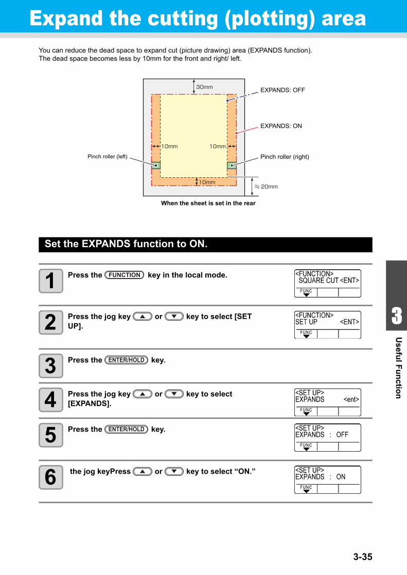
3-35
1
1
3
Usefu
l Fu
nctio
n
5
6
Expand the cutting (plotting) area You can reduce the dead space to expand cut (picture drawing) area (EXPANDS function).The dead space becomes less by 10mm for the front and right/ left.
Set the EXPANDS function to ON.
1 Press the key in the local mode.
2 Press the jog key or key to select [SET UP].
3 Press the key.
4 Press the jog key or key to select [EXPANDS].
5 Press the key.
6 the jog keyPress or key to select “ON.”
Pinch roller (left) Pinch roller (right)
EXPANDS: OFF
EXPANDS: ON
When the sheet is set in the rear
FUNCTION
ENTER/HOLD
ENTER/HOLD
3-36
Expand the cutting (plotting) area
7 Press the key.
8 Press the key twice for terminating this function.
Set EXPANDS function to “OFF”.
• When the Expand mode is set to ON, paper jam can occur if excessive pressure is applied to the sheet.
• If axis compensation is not performed, the cutter blade can run out of the sheet and may cause a paper jam. A cutter blade having run out of the sheet may damage itself or the plotter.
• The cutting quality of the areas that come in contact with the pinch rollers will be lowered.• If a pinch roller comes in contact with a registration mark during its detection, the registration mark
may not be detected properly.• Once the Expand function is set after sheet detection, be sure to perform sheet detection again.
Follow the Steps 1 to 5 of “Set the EXPANDS
function to ON.”
Press the jog key
to select “OFF.”
Press the
key.
Press the
key twice.
ENTER/HOLD
END
ENTER/HOLD END
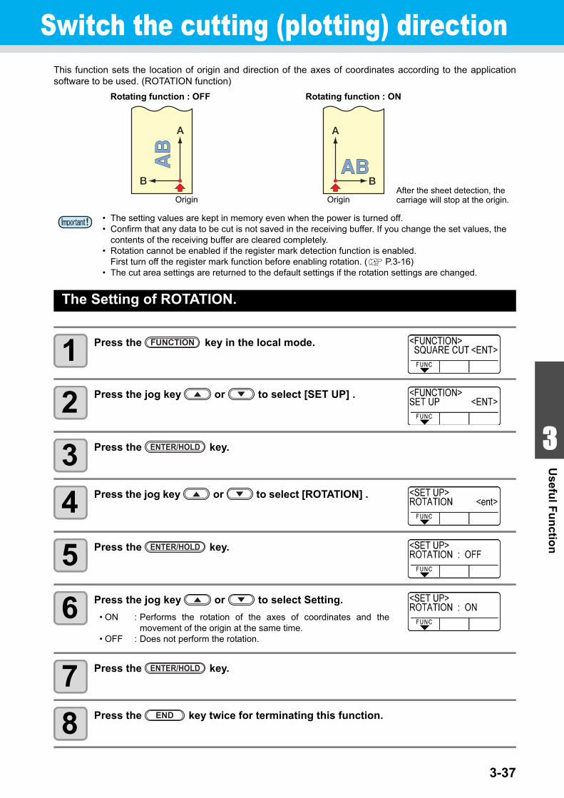
3-37
1
1
3
Usefu
l Fu
nctio
n
5
6
Switch the cutting (plotting) direction This function sets the location of origin and direction of the axes of coordinates according to the applicationsoftware to be used. (ROTATION function)
The Setting of ROTATION.
1 Press the key in the local mode.
2 Press the jog key or to select [SET UP] .
3 Press the key.
4 Press the jog key or to select [ROTATION] .
5 Press the key.
6 Press the jog key or to select Setting.
• ON : Performs the rotation of the axes of coordinates and themovement of the origin at the same time.
• OFF : Does not perform the rotation.
7 Press the key.
8 Press the key twice for terminating this function.
• The setting values are kept in memory even when the power is turned off.• Confirm that any data to be cut is not saved in the receiving buffer. If you change the set values, the
contents of the receiving buffer are cleared completely.• Rotation cannot be enabled if the register mark detection function is enabled.
First turn off the register mark function before enabling rotation. ( P.3-16)• The cut area settings are returned to the default settings if the rotation settings are changed.
Rotating function : OFF
Origin
Rotating function : ON
OriginAfter the sheet detection, the carriage will stop at the origin.
FUNCTION
ENTER/HOLD
ENTER/HOLD
ENTER/HOLD
END
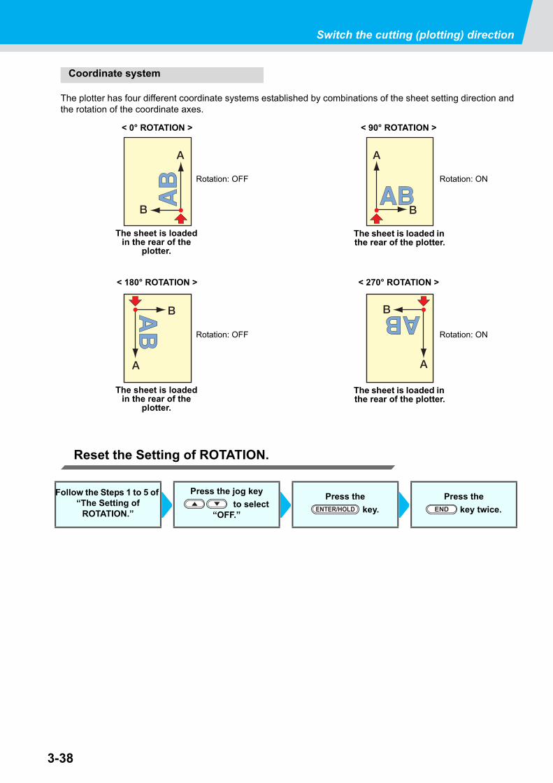
3-38
Switch the cutting (plotting) direction
Coordinate system
The plotter has four different coordinate systems established by combinations of the sheet setting direction andthe rotation of the coordinate axes.
Reset the Setting of ROTATION.
Follow the Steps 1 to 5 of “The Setting of
ROTATION.”
Press the jog key
to select “OFF.”
Press the
key.
Press the
key twice.
< 0° ROTATION >
The sheet is loaded in the rear of the
plotter.
< 90° ROTATION >
The sheet is loaded in the rear of the plotter.
Rotation: OFF Rotation: ON
Rotation: OFF Rotation: ON
The sheet is loaded in the rear of the
plotter.
The sheet is loaded in the rear of the plotter.
< 180° ROTATION > < 270° ROTATION >
ENTER/HOLD END
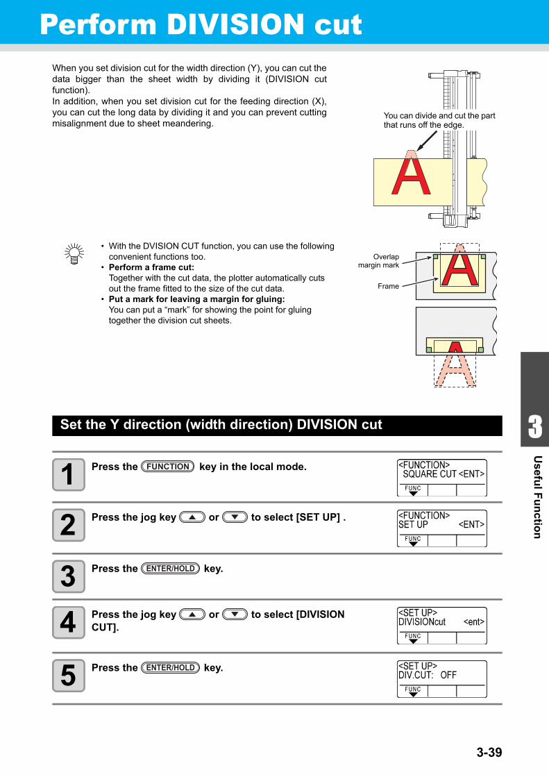
3-39
1
1
3
Usefu
l Fu
nctio
n
5
6
Perform DIVISION cutWhen you set division cut for the width direction (Y), you can cut thedata bigger than the sheet width by dividing it (DIVISION cutfunction).In addition, when you set division cut for the feeding direction (X),you can cut the long data by dividing it and you can prevent cuttingmisalignment due to sheet meandering.
Set the Y direction (width direction) DIVISION cut
1 Press the key in the local mode.
2 Press the jog key or to select [SET UP] .
3 Press the key.
4 Press the jog key or to select [DIVISION CUT].
5 Press the key.
• With the DVISION CUT function, you can use the following convenient functions too.
• Perform a frame cut:Together with the cut data, the plotter automatically cuts out the frame fitted to the size of the cut data.
• Put a mark for leaving a margin for gluing:You can put a “mark” for showing the point for gluing together the division cut sheets.
You can divide and cut the part that runs off the edge.
Overlapmargin mark
Frame
FUNCTION
ENTER/HOLD
ENTER/HOLD
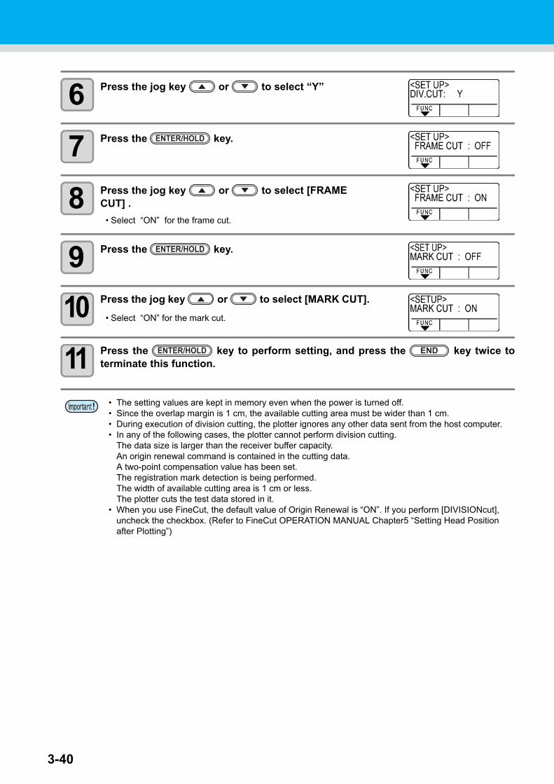
3-40
6 Press the jog key or to select “Y”
7 Press the key.
8 Press the jog key or to select [FRAME CUT] .
• Select “ON” for the frame cut.
9 Press the key.
10 Press the jog key or to select [MARK CUT].
• Select “ON” for the mark cut.
11 Press the key to perform setting, and press the key twice toterminate this function.
• The setting values are kept in memory even when the power is turned off.• Since the overlap margin is 1 cm, the available cutting area must be wider than 1 cm.• During execution of division cutting, the plotter ignores any other data sent from the host computer.• In any of the following cases, the plotter cannot perform division cutting.
The data size is larger than the receiver buffer capacity.An origin renewal command is contained in the cutting data.A two-point compensation value has been set.The registration mark detection is being performed.The width of available cutting area is 1 cm or less.The plotter cuts the test data stored in it.
• When you use FineCut, the default value of Origin Renewal is “ON”. If you perform [DIVISIONcut], uncheck the checkbox. (Refer to FineCut OPERATION MANUAL Chapter5 “Setting Head Position after Plotting”)
ENTER/HOLD
ENTER/HOLD
ENTER/HOLD END
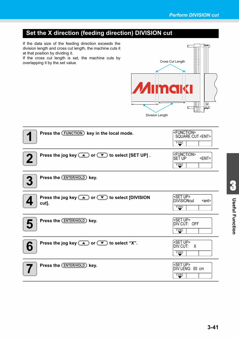
3-41
1
1
3
Usefu
l Fu
nctio
n
5
6
Perform DIVISION cut
Set the X direction (feeding direction) DIVISION cut
If the data size of the feeding direction exceeds thedivision length and cross cut length, the machine cuts itat that position by dividing it.If the cross cut length is set, the machine cuts byoverlapping it by the set value.
1 Press the key in the local mode.
2 Press the jog key or to select [SET UP] .
3 Press the key.
4 Press the jog key or to select [DIVISION cut].
5 Press the key.
6 Press the jog key or to select “X”.
7 Press the key.
Cross Cut Length
Division Length
FUNCTION
ENTER/HOLD
ENTER/HOLD
ENTER/HOLD
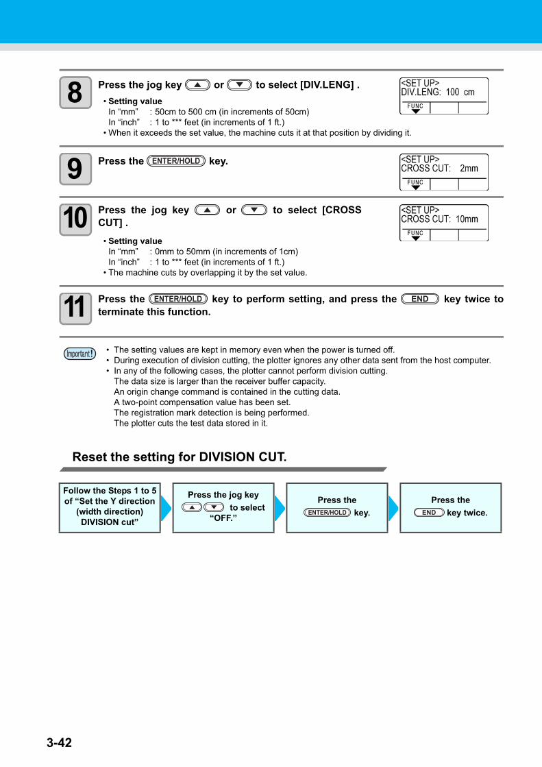
3-42
8 Press the jog key or to select [DIV.LENG] .
• Setting valueIn “mm” : 50cm to 500 cm (in increments of 50cm)In “inch” : 1 to *** feet (in increments of 1 ft.)
• When it exceeds the set value, the machine cuts it at that position by dividing it.
9 Press the key.
10 Press the jog key or to select [CROSSCUT] .
• Setting valueIn “mm” : 0mm to 50mm (in increments of 1cm)In “inch” : 1 to *** feet (in increments of 1 ft.)
• The machine cuts by overlapping it by the set value.
11 Press the key to perform setting, and press the key twice toterminate this function.
Reset the setting for DIVISION CUT.
• The setting values are kept in memory even when the power is turned off.• During execution of division cutting, the plotter ignores any other data sent from the host computer.• In any of the following cases, the plotter cannot perform division cutting.
The data size is larger than the receiver buffer capacity.An origin change command is contained in the cutting data.A two-point compensation value has been set.The registration mark detection is being performed.The plotter cuts the test data stored in it.
Follow the Steps 1 to 5 of “Set the Y direction
(width direction) DIVISION cut”
Press the jog key
to select “OFF.”
Press the
key.
Press the
key twice.
ENTER/HOLD
ENTER/HOLD END
ENTER/HOLD END
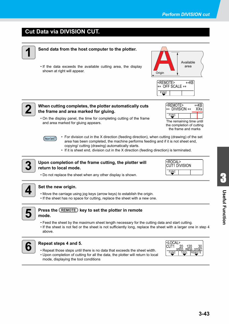
3-43
1
1
3
Usefu
l Fu
nctio
n
5
6
Perform DIVISION cut
Cut Data via DIVISION CUT.
1 Send data from the host computer to the plotter.
• If the data exceeds the available cutting area, the displayshown at right will appear.
2 When cutting completes, the plotter automatically cuts the frame and area marked for gluing.
• On the display panel, the time for completing cutting of the frameand area marked for gluing appears.
3 Upon completion of the frame cutting, the plotter will return to local mode.
• Do not replace the sheet when any other display is shown.
4 Set the new origin.
• Move the carriage using jog keys (arrow keys) to establish the origin.• If the sheet has no space for cutting, replace the sheet with a new one.
5 Press the key to set the plotter in remote mode.
• Feed the sheet by the maximum sheet length necessary for the cutting data and start cutting.• If the sheet is not fed or the sheet is not sufficiently long, replace the sheet with a larger one in step 4
above.
6 Repeat steps 4 and 5.
• Repeat those steps until there is no data that exceeds the sheet width.• Upon completion of cutting for all the data, the plotter will return to local
mode, displaying the tool conditions
• For division cut in the X direction (feeding direction), when cutting (drawing) of the set area has been completed, the machine performs feeding and if it is not sheet end, copying/ cutting (drawing) automatically starts.
• If it is sheet end, division cut in the X direction (feeding direction) is terminated.
Availablearea
Origin
The remaining time untilthe completion of cutting
the frame and marks
REMOTE
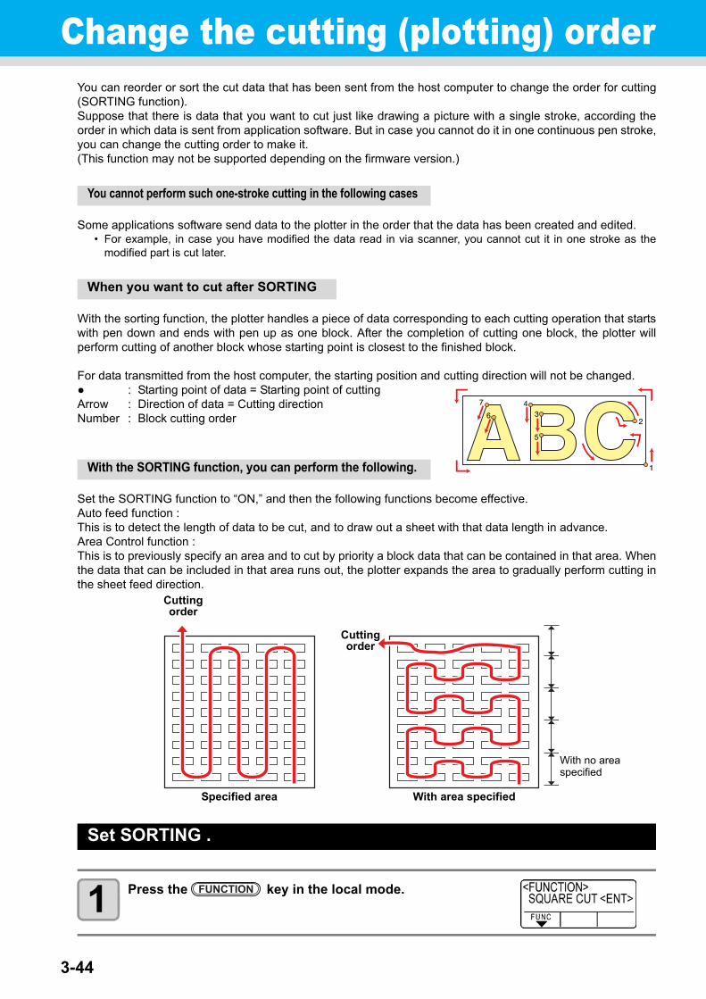
3-44
Change the cutting (plotting) orderYou can reorder or sort the cut data that has been sent from the host computer to change the order for cutting(SORTING function).Suppose that there is data that you want to cut just like drawing a picture with a single stroke, according theorder in which data is sent from application software. But in case you cannot do it in one continuous pen stroke,you can change the cutting order to make it.(This function may not be supported depending on the firmware version.)
You cannot perform such one-stroke cutting in the following cases
Some applications software send data to the plotter in the order that the data has been created and edited.• For example, in case you have modified the data read in via scanner, you cannot cut it in one stroke as the
modified part is cut later.
When you want to cut after SORTING
With the sorting function, the plotter handles a piece of data corresponding to each cutting operation that startswith pen down and ends with pen up as one block. After the completion of cutting one block, the plotter willperform cutting of another block whose starting point is closest to the finished block.
For data transmitted from the host computer, the starting position and cutting direction will not be changed.● : Starting point of data = Starting point of cuttingArrow : Direction of data = Cutting directionNumber : Block cutting order
With the SORTING function, you can perform the following.
Set the SORTING function to “ON,” and then the following functions become effective.Auto feed function :This is to detect the length of data to be cut, and to draw out a sheet with that data length in advance.Area Control function :This is to previously specify an area and to cut by priority a block data that can be contained in that area. Whenthe data that can be included in that area runs out, the plotter expands the area to gradually perform cutting inthe sheet feed direction.
Set SORTING .
1 Press the key in the local mode.
Specified area With area specified
With no areaspecified
Cuttingorder
Cuttingorder
FUNCTION
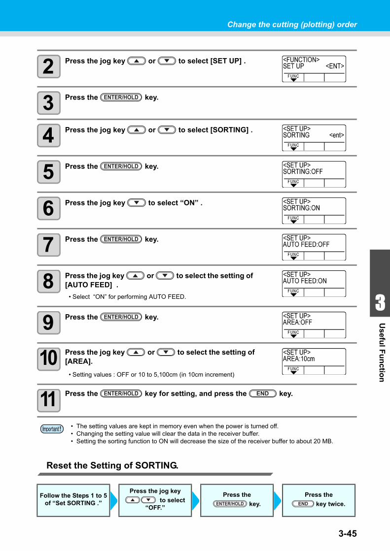
3-45
1
1
3
Usefu
l Fu
nctio
n
5
6
Change the cutting (plotting) order
2 Press the jog key or to select [SET UP] .
3 Press the key.
4 Press the jog key or to select [SORTING] .
5 Press the key.
6 Press the jog key to select “ON” .
7 Press the key.
8 Press the jog key or to select the setting of [AUTO FEED] .
• Select “ON” for performing AUTO FEED.
9 Press the key.
10 Press the jog key or to select the setting of[AREA].
• Setting values : OFF or 10 to 5,100cm (in 10cm increment)
11 Press the key for setting, and press the key.
Reset the Setting of SORTING.
• The setting values are kept in memory even when the power is turned off.• Changing the setting value will clear the data in the receiver buffer.• Setting the sorting function to ON will decrease the size of the receiver buffer to about 20 MB.
Follow the Steps 1 to 5 of “Set SORTING .”
Press the jog key
to select “OFF.”
Press the
key.
Press the
key twice.
ENTER/HOLD
ENTER/HOLD
ENTER/HOLD
ENTER/HOLD
ENTER/HOLD END
ENTER/HOLD END
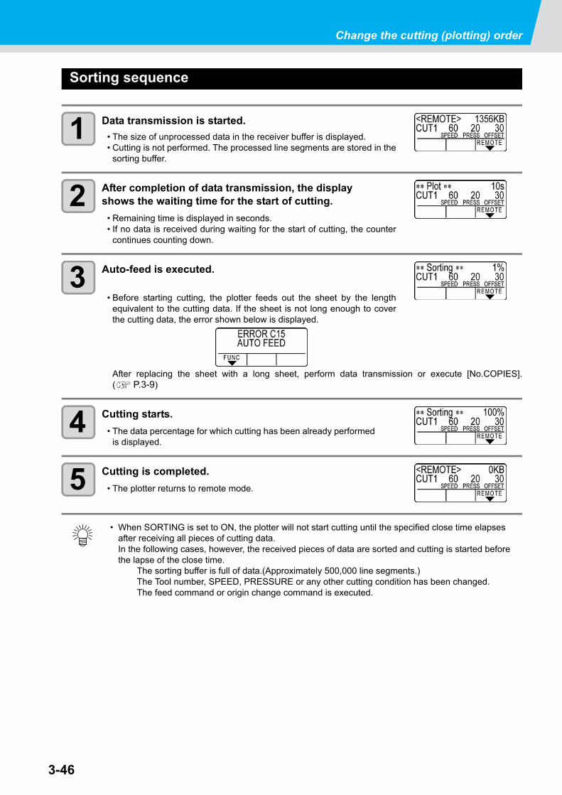
3-46
Change the cutting (plotting) order
Sorting sequence
1 Data transmission is started.
• The size of unprocessed data in the receiver buffer is displayed.• Cutting is not performed. The processed line segments are stored in the
sorting buffer.
2 After completion of data transmission, the display shows the waiting time for the start of cutting.
• Remaining time is displayed in seconds.• If no data is received during waiting for the start of cutting, the counter
continues counting down.
3 Auto-feed is executed.
• Before starting cutting, the plotter feeds out the sheet by the lengthequivalent to the cutting data. If the sheet is not long enough to coverthe cutting data, the error shown below is displayed.
After replacing the sheet with a long sheet, perform data transmission or execute [No.COPIES].( P.3-9)
4 Cutting starts.
• The data percentage for which cutting has been already performedis displayed.
5 Cutting is completed.
• The plotter returns to remote mode.
• When SORTING is set to ON, the plotter will not start cutting until the specified close time elapses after receiving all pieces of cutting data.In the following cases, however, the received pieces of data are sorted and cutting is started before the lapse of the close time.
The sorting buffer is full of data.(Approximately 500,000 line segments.)The Tool number, SPEED, PRESSURE or any other cutting condition has been changed.The feed command or origin change command is executed.
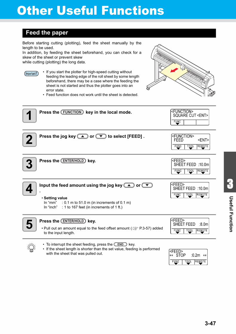
1
1
3
Usefu
l Fu
nctio
n
5
63-47
Other Useful FunctionsFeed the paper
Before starting cutting (plotting), feed the sheet manually by thelength to be used.In addition, by feeding the sheet beforehand, you can check for askew of the sheet or prevent skewwhile cutting (plotting) the long data.
1 Press the key in the local mode.
2 Press the jog key or to select [FEED] .
3 Press the key.
4 Input the feed amount using the jog key or .
• Setting valueIn “mm” : 0.1 m to 51.0 m (in increments of 0.1 m)In “inch” : 1 to 167 feet (in increments of 1 ft.)
5 Press the key.
• Pull out an amount equal to the feed offset amount ( P.3-57) addedto the input length.
• If you start the plotter for high-speed cutting without feeding the leading edge of the roll sheet by some length beforehand, there may be a case where the feeding the sheet is not started and thus the plotter goes into an error state.
• Feed function does not work until the sheet is detected.
• To interrupt the sheet feeding, press the key.• If the sheet length is shorter than the set value, feeding is performed
with the sheet that was pulled out.
FUNCTION
ENTER/HOLD
ENTER/HOLD
END
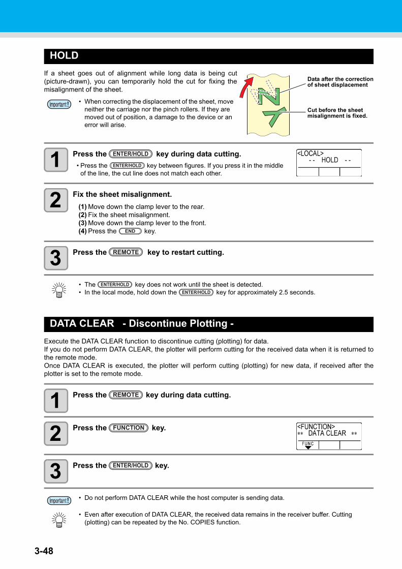
3-48
HOLD
If a sheet goes out of alignment while long data is being cut(picture-drawn), you can temporarily hold the cut for fixing themisalignment of the sheet.
1 Press the key during data cutting.
• Press the key between figures. If you press it in the middleof the line, the cut line does not match each other.
2 Fix the sheet misalignment.
(1) Move down the clamp lever to the rear.(2) Fix the sheet misalignment.(3) Move down the clamp lever to the front.(4) Press the key.
3 Press the key to restart cutting.
DATA CLEAR - Discontinue Plotting -
Execute the DATA CLEAR function to discontinue cutting (plotting) for data.If you do not perform DATA CLEAR, the plotter will perform cutting for the received data when it is returned tothe remote mode.Once DATA CLEAR is executed, the plotter will perform cutting (plotting) for new data, if received after theplotter is set to the remote mode.
1 Press the key during data cutting.
2 Press the key.
3 Press the key.
• When correcting the displacement of the sheet, move neither the carriage nor the pinch rollers. If they are moved out of position, a damage to the device or an error will arise.
• The key does not work until the sheet is detected.• In the local mode, hold down the key for approximately 2.5 seconds.
• Do not perform DATA CLEAR while the host computer is sending data.
• Even after execution of DATA CLEAR, the received data remains in the receiver buffer. Cutting (plotting) can be repeated by the No. COPIES function.
Data after the correctionof sheet displacement
Cut before the sheet misalignment is fixed.
ENTER/HOLD
ENTER/HOLD
END
REMOTE
ENTER/HOLDENTER/HOLD
REMOTE
FUNCTION
ENTER/HOLD
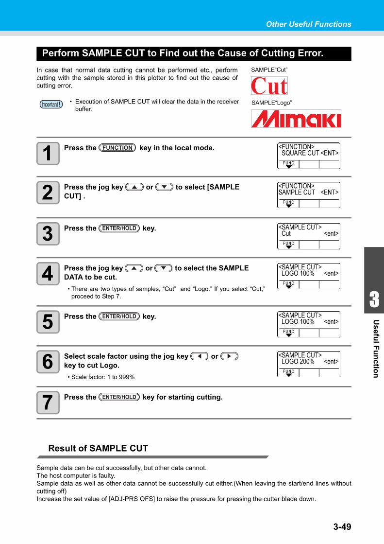
Other Useful Functions
1
1
3
Usefu
l Fu
nctio
n
5
63-49
Perform SAMPLE CUT to Find out the Cause of Cutting Error.
In case that normal data cutting cannot be performed etc., performcutting with the sample stored in this plotter to find out the cause ofcutting error.
1 Press the key in the local mode.
2 Press the jog key or to select [SAMPLE CUT] .
3 Press the key.
4 Press the jog key or to select the SAMPLE DATA to be cut.
• There are two types of samples, “Cut” and “Logo.” If you select “Cut,”proceed to Step 7.
5 Press the key.
6 Select scale factor using the jog key or key to cut Logo.
• Scale factor: 1 to 999%
7 Press the key for starting cutting.
Result of SAMPLE CUT
Sample data can be cut successfully, but other data cannot.The host computer is faulty.Sample data as well as other data cannot be successfully cut either.(When leaving the start/end lines withoutcutting off)Increase the set value of [ADJ-PRS OFS] to raise the pressure for pressing the cutter blade down.
• Execution of SAMPLE CUT will clear the data in the receiver buffer.
SAMPLE“Cut”
SAMPLE“Logo”
FUNCTION
ENTER/HOLD
ENTER/HOLD
ENTER/HOLD
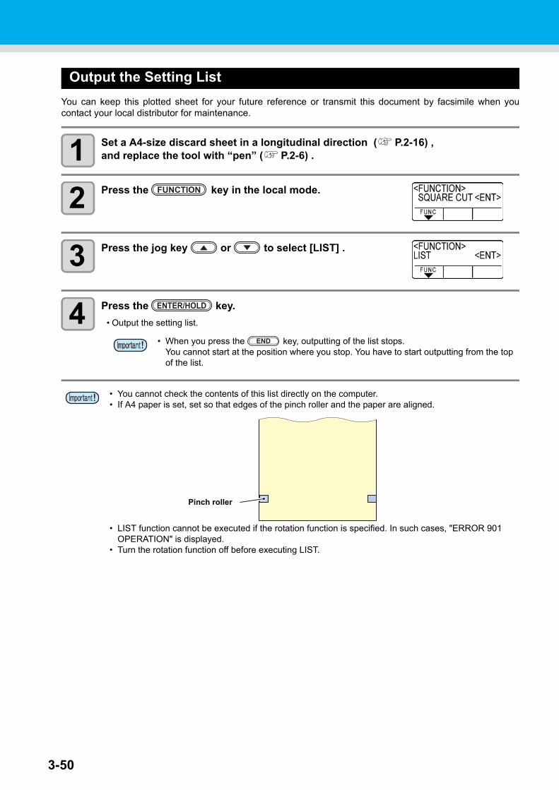
3-50
Output the Setting List
You can keep this plotted sheet for your future reference or transmit this document by facsimile when youcontact your local distributor for maintenance.
1 Set a A4-size discard sheet in a longitudinal direction ( P.2-16) ,and replace the tool with “pen” ( P.2-6) .
2 Press the key in the local mode.
3 Press the jog key or to select [LIST] .
4 Press the key.
• Output the setting list.
• When you press the key, outputting of the list stops.You cannot start at the position where you stop. You have to start outputting from the top of the list.
• You cannot check the contents of this list directly on the computer.• If A4 paper is set, set so that edges of the pinch roller and the paper are aligned.
• LIST function cannot be executed if the rotation function is specified. In such cases, "ERROR 901 OPERATION" is displayed.
• Turn the rotation function off before executing LIST.
FUNCTION
ENTER/HOLD
END
Pinch roller
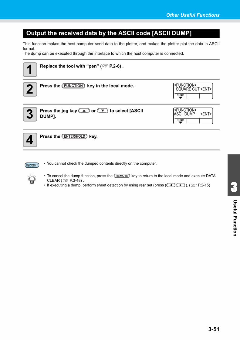
Other Useful Functions
1
1
3
Usefu
l Fu
nctio
n
5
63-51
Output the received data by the ASCII code [ASCII DUMP]
This function makes the host computer send data to the plotter, and makes the plotter plot the data in ASCIIformat.The dump can be executed through the interface to which the host computer is connected.
1 Replace the tool with “pen” ( P.2-6) .
2 Press the key in the local mode.
3 Press the jog key or to select [ASCII DUMP].
4 Press the key.
• You cannot check the dumped contents directly on the computer.
• To cancel the dump function, press the key to return to the local mode and execute DATA CLEAR ( P.3-48) ,
• If executing a dump, perform sheet detection by using rear set (press ( ). ( P.2-15)
FUNCTION
ENTER/HOLD
REMOTE
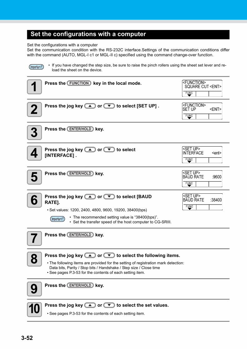
3-52
Set the configurations with a computer
Set the configurations with a computer Set the communication condition with the RS-232C interface.Settings of the communication conditions differwith the command (AUTO, MGL-I c1 or MGL-II c) specified using the command change-over function.
1 Press the key in the local mode.
2 Press the jog key or to select [SET UP] .
3 Press the key.
4 Press the jog key or to select [INTERFACE] .
5 Press the key.
6 Press the jog key or to select [BAUD RATE].
• Set values: 1200, 2400, 4800, 9600, 19200, 38400(bps)
7 Press the key.
8 Press the jog key or to select the following items.
• The following items are provided for the setting of registration mark detection:Data bits, Parity / Stop bits / Handshake / Step size / Close time
• See pages P.3-53 for the contents of each setting item.
9 Press the key.
10 Press the jog key or to select the set values.
• See pages P.3-53 for the contents of each setting item.
• If you have changed the step size, be sure to raise the pinch rollers using the sheet set lever and re-load the sheet on the device.
• The recommended setting value is “38400(bps)”.• Set the transfer speed of the host computer to CG-SRIII.
FUNCTION
ENTER/HOLD
ENTER/HOLD
ENTER/HOLD
ENTER/HOLD
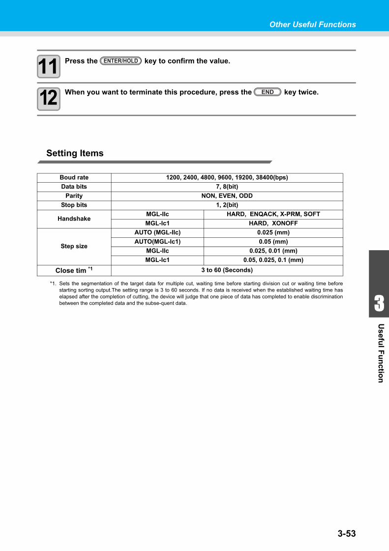
Other Useful Functions
1
1
3
Usefu
l Fu
nctio
n
5
63-53
11 Press the key to confirm the value.
12 When you want to terminate this procedure, press the key twice.
Setting Items
Boud rate 1200, 2400, 4800, 9600, 19200, 38400(bps)
Data bits 7, 8(bit)
Parity NON, EVEN, ODD
Stop bits 1, 2(bit)
HandshakeMGL-IIc HARD, ENQACK, X-PRM, SOFT
MGL-Ic1 HARD, XONOFF
Step size
AUTO (MGL-IIc) 0.025 (mm)
AUTO(MGL-Ic1) 0.05 (mm)
MGL-IIc 0.025, 0.01 (mm)
MGL-Ic1 0.05, 0.025, 0.1 (mm)
Close tim *1
*1. Sets the segmentation of the target data for multiple cut, waiting time before starting division cut or waiting time beforestarting sorting output.The setting range is 3 to 60 seconds. If no data is received when the established waiting time haselapsed after the completion of cutting, the device will judge that one piece of data has completed to enable discriminationbetween the completed data and the subse-quent data.
3 to 60 (Seconds)
ENTER/HOLD
END
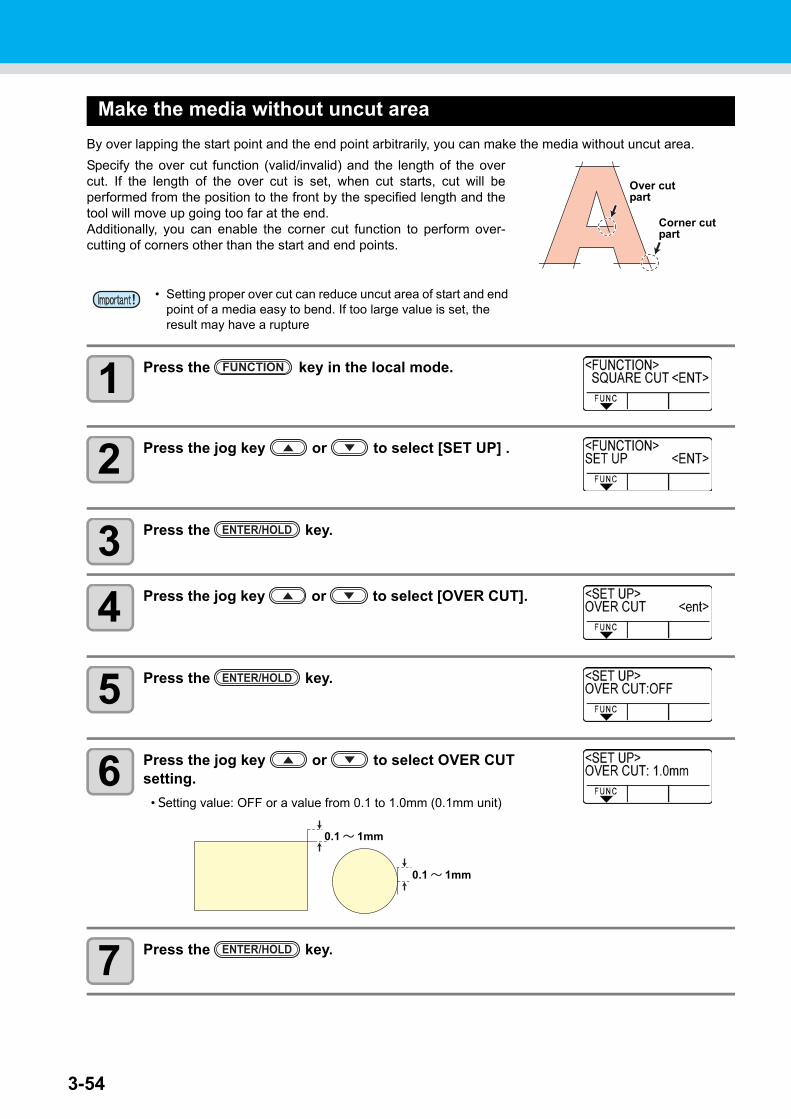
3-54
Make the media without uncut area
By over lapping the start point and the end point arbitrarily, you can make the media without uncut area.
Specify the over cut function (valid/invalid) and the length of the overcut. If the length of the over cut is set, when cut starts, cut will beperformed from the position to the front by the specified length and thetool will move up going too far at the end.Additionally, you can enable the corner cut function to perform over-cutting of corners other than the start and end points.
1 Press the key in the local mode.
2 Press the jog key or to select [SET UP] .
3 Press the key.
4 Press the jog key or to select [OVER CUT].
5 Press the key.
6 Press the jog key or to select OVER CUT setting.
• Setting value: OFF or a value from 0.1 to 1.0mm (0.1mm unit)
7 Press the key.
• Setting proper over cut can reduce uncut area of start and end point of a media easy to bend. If too large value is set, the result may have a rupture
Over cut part
Corner cut part
FUNCTION
ENTER/HOLD
ENTER/HOLD
0.1 ~ 1mm
0.1 ~ 1mm
ENTER/HOLD
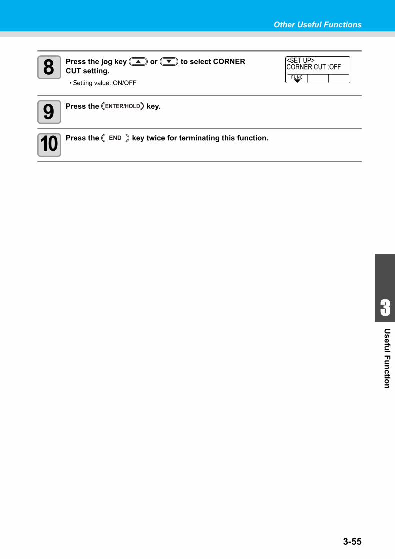
Other Useful Functions
1
1
3
Usefu
l Fu
nctio
n
5
63-55
8 Press the jog key or to select CORNER CUT setting.
• Setting value: ON/OFF
9 Press the key.
10 Press the key twice for terminating this function.
ENTER/HOLD
END
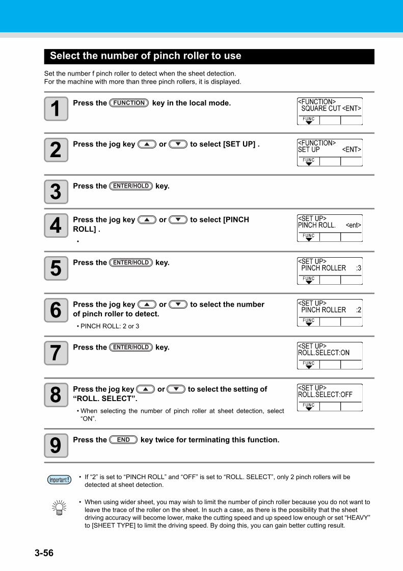
3-56
Select the number of pinch roller to use
Set the number f pinch roller to detect when the sheet detection.For the machine with more than three pinch rollers, it is displayed.
1 Press the key in the local mode.
2 Press the jog key or to select [SET UP] .
3 Press the key.
4 Press the jog key or to select [PINCH ROLL] .
•
5 Press the key.
6 Press the jog key or to select the number of pinch roller to detect.
• PINCH ROLL: 2 or 3
7 Press the key.
8 Press the jog key or to select the setting of “ROLL. SELECT”.
• When selecting the number of pinch roller at sheet detection, select“ON”.
9 Press the key twice for terminating this function.
• If “2” is set to “PINCH ROLL” and “OFF” is set to “ROLL. SELECT”, only 2 pinch rollers will be detected at sheet detection.
• When using wider sheet, you may wish to limit the number of pinch roller because you do not want to leave the trace of the roller on the sheet. In such a case, as there is the possibility that the sheet driving accuracy will become lower, make the cutting speed and up speed low enough or set “HEAVY” to [SHEET TYPE] to limit the driving speed. By doing this, you can gain better cutting result.
FUNCTION
ENTER/HOLD
ENTER/HOLD
ENTER/HOLD
END
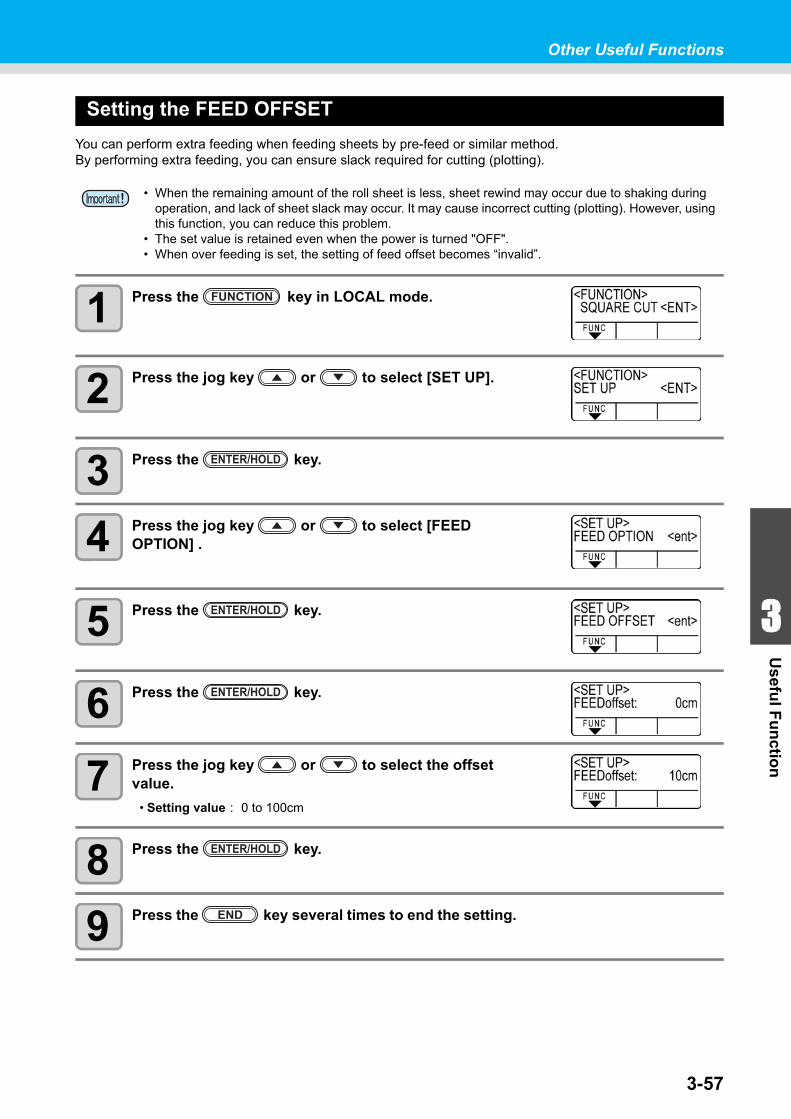
Other Useful Functions
1
1
3
Usefu
l Fu
nctio
n
5
63-57
Setting the FEED OFFSET
You can perform extra feeding when feeding sheets by pre-feed or similar method.By performing extra feeding, you can ensure slack required for cutting (plotting).
1 Press the key in LOCAL mode.
2 Press the jog key or to select [SET UP].
3 Press the key.
4 Press the jog key or to select [FEED OPTION] .
5 Press the key.
6 Press the key.
7 Press the jog key or to select the offset value.
• Setting value : 0 to 100cm
8 Press the key.
9 Press the key several times to end the setting.
• When the remaining amount of the roll sheet is less, sheet rewind may occur due to shaking during operation, and lack of sheet slack may occur. It may cause incorrect cutting (plotting). However, using this function, you can reduce this problem.
• The set value is retained even when the power is turned "OFF".• When over feeding is set, the setting of feed offset becomes “invalid”.
FUNCTION
ENTER/HOLD
ENTER/HOLD
ENTER/HOLD
ENTER/HOLD
END
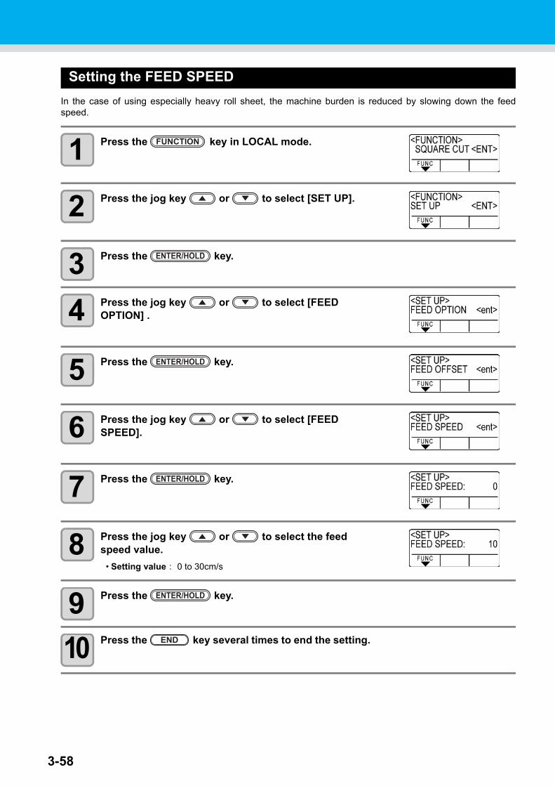
3-58
Setting the FEED SPEED
In the case of using especially heavy roll sheet, the machine burden is reduced by slowing down the feedspeed.
1 Press the key in LOCAL mode.
2 Press the jog key or to select [SET UP].
3 Press the key.
4 Press the jog key or to select [FEED OPTION] .
5 Press the key.
6 Press the jog key or to select [FEED SPEED].
7 Press the key.
8 Press the jog key or to select the feed speed value.
• Setting value : 0 to 30cm/s
9 Press the key.
10 Press the key several times to end the setting.
FUNCTION
ENTER/HOLD
ENTER/HOLD
ENTER/HOLD
ENTER/HOLD
END
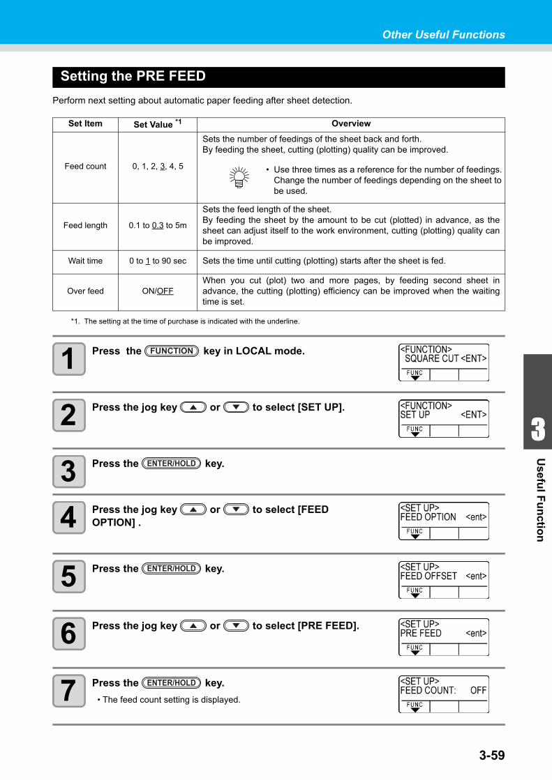
Other Useful Functions
1
1
3
Usefu
l Fu
nctio
n
5
63-59
Setting the PRE FEED
Perform next setting about automatic paper feeding after sheet detection.
1 Press the key in LOCAL mode.
2 Press the jog key or to select [SET UP].
3 Press the key.
4 Press the jog key or to select [FEED OPTION] .
5 Press the key.
6 Press the jog key or to select [PRE FEED].
7 Press the key.
• The feed count setting is displayed.
Set Item Set Value *1
*1. The setting at the time of purchase is indicated with the underline.
Overview
Feed count 0, 1, 2, 3, 4, 5
Sets the number of feedings of the sheet back and forth.By feeding the sheet, cutting (plotting) quality can be improved.
Feed length 0.1 to 0.3 to 5m
Sets the feed length of the sheet.By feeding the sheet by the amount to be cut (plotted) in advance, as thesheet can adjust itself to the work environment, cutting (plotting) quality canbe improved.
Wait time 0 to 1 to 90 sec Sets the time until cutting (plotting) starts after the sheet is fed.
Over feed ON/OFFWhen you cut (plot) two and more pages, by feeding second sheet inadvance, the cutting (plotting) efficiency can be improved when the waitingtime is set.
• Use three times as a reference for the number of feedings. Change the number of feedings depending on the sheet to be used.
FUNCTION
ENTER/HOLD
ENTER/HOLD
ENTER/HOLD
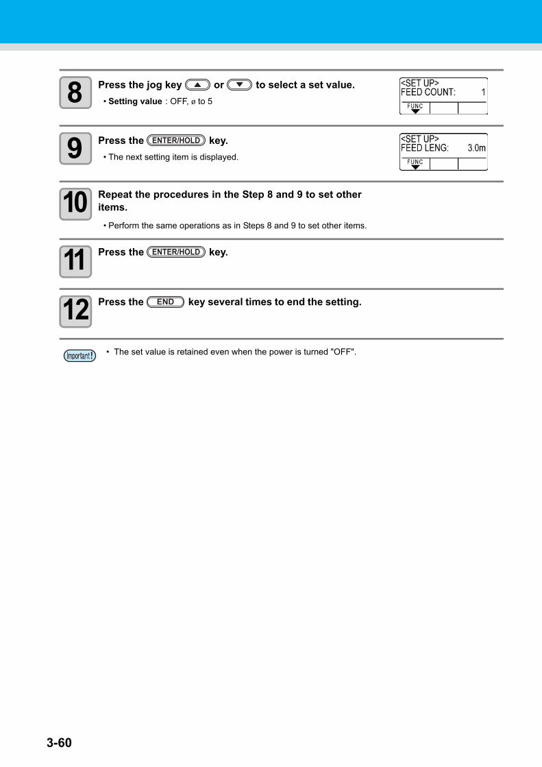
3-60
8 Press the jog key or to select a set value.
• Setting value : OFF, 1 to 5
9 Press the key.
• The next setting item is displayed.
10 Repeat the procedures in the Step 8 and 9 to set otheritems.
• Perform the same operations as in Steps 8 and 9 to set other items.
11 Press the key.
12 Press the key several times to end the setting.
• The set value is retained even when the power is turned "OFF".
ENTER/HOLD
ENTER/HOLD
END
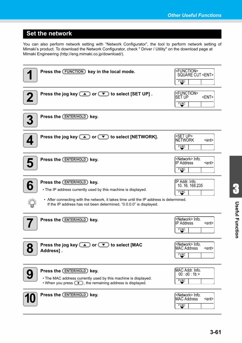
Other Useful Functions
1
1
3
Usefu
l Fu
nctio
n
5
63-61
Set the network
You can also perform network setting with “Network Configurator”, the tool to perform network setting ofMimaki’s product. To download the Network Configurator, check " Driver / Utility" on the download page atMimaki Engineering (http://eng.mimaki.co.jp/download/).
1 Press the key in the local mode.
2 Press the jog key or to select [SET UP] .
3 Press the key.
4 Press the jog key or to select [NETWORK].
5 Press the key.
6 Press the key.
• The IP address currently used by this machine is displayed.
7 Press the key.
8 Press the jog key or to select [MAC Address] .
9 Press the key.
• The MAC address currently used by this machine is displayed.• When you press , the remaining address is displayed.
10 Press the key.
• After connecting with the network, it takes time until the IP address is determined.If the IP address has not been determined, “0.0.0.0” is displayed.
FUNCTION
ENTER/HOLD
ENTER/HOLD
ENTER/HOLD
ENTER/HOLD
ENTER/HOLD
ENTER/HOLD
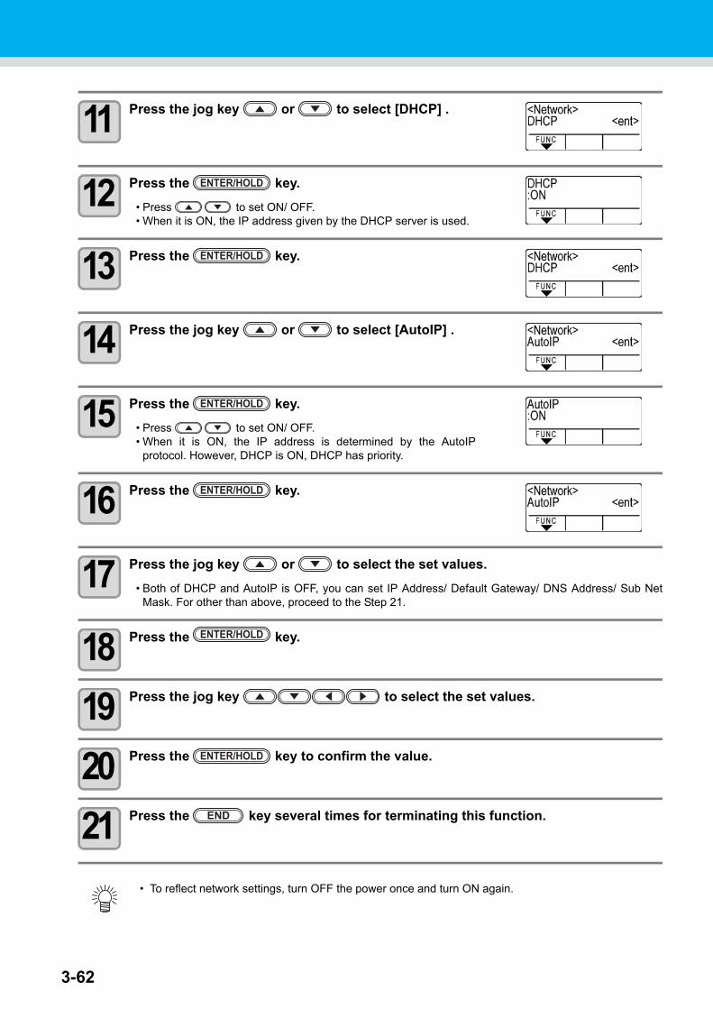
3-62
11 Press the jog key or to select [DHCP] .
12 Press the key.
• Press to set ON/ OFF.• When it is ON, the IP address given by the DHCP server is used.
13 Press the key.
14 Press the jog key or to select [AutoIP] .
15 Press the key.
• Press to set ON/ OFF.• When it is ON, the IP address is determined by the AutoIP
protocol. However, DHCP is ON, DHCP has priority.
16 Press the key.
17 Press the jog key or to select the set values.
• Both of DHCP and AutoIP is OFF, you can set IP Address/ Default Gateway/ DNS Address/ Sub NetMask. For other than above, proceed to the Step 21.
18 Press the key.
19 Press the jog key to select the set values.
20 Press the key to confirm the value.
21 Press the key several times for terminating this function.
• To reflect network settings, turn OFF the power once and turn ON again.
ENTER/HOLD
ENTER/HOLD
ENTER/HOLD
ENTER/HOLD
ENTER/HOLD
ENTER/HOLD
END
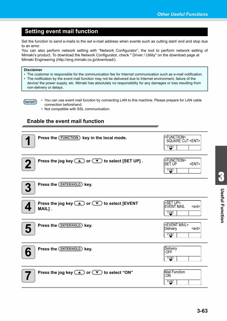
Other Useful Functions
1
1
3
Usefu
l Fu
nctio
n
5
63-63
Setting event mail function
Set the function to send e-mails to the set e-mail address when events such as cutting start/ end and stop dueto an error.You can also perform network setting with “Network Configurator”, the tool to perform network setting ofMimaki’s product. To download the Network Configurator, check " Driver / Utility" on the download page atMimaki Engineering (http://eng.mimaki.co.jp/download/).
Enable the event mail function
1 Press the key in the local mode.
2 Press the jog key or to select [SET UP] .
3 Press the key.
4 Press the jog key or to select [EVENT MAIL] .
5 Press the key.
6 Press the key.
7 Press the jog key or to select “ON”
Disclaimer• The customer is responsible for the communication fee for Internet communication such as e-mail notification.• The notification by the event mail function may not be delivered due to Internet environment, failure of the
device/ the power supply, etc. Mimaki has absolutely no responsibility for any damages or loss resulting from non-delivery or delays.
• You can use event mail function by connecting LAN to this machine. Please prepare for LAN cable connection beforehand.
• Not compatible with SSL communication.
FUNCTION
ENTER/HOLD
ENTER/HOLD
ENTER/HOLD

3-64
8 Press the key.
9 Press the key several times for terminating this function.
ENTER/HOLD
END
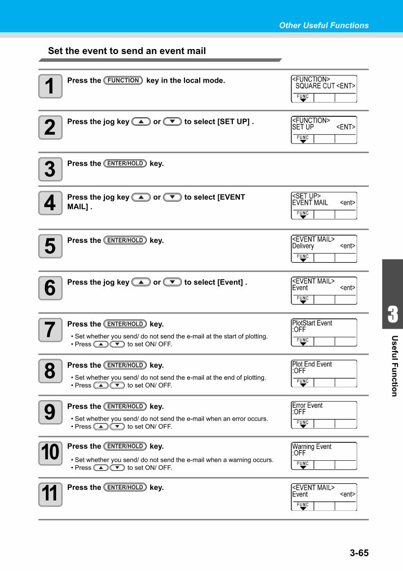
Other Useful Functions
1
1
3
Usefu
l Fu
nctio
n
5
63-65
Set the event to send an event mail
1 Press the key in the local mode.
2 Press the jog key or to select [SET UP] .
3 Press the key.
4 Press the jog key or to select [EVENT MAIL] .
5 Press the key.
6 Press the jog key or to select [Event] .
7 Press the key.
• Set whether you send/ do not send the e-mail at the start of plotting.• Press to set ON/ OFF.
8 Press the key.
• Set whether you send/ do not send the e-mail at the end of plotting.• Press to set ON/ OFF.
9 Press the key.
• Set whether you send/ do not send the e-mail when an error occurs.• Press to set ON/ OFF.
10 Press the key.
• Set whether you send/ do not send the e-mail when a warning occurs.• Press to set ON/ OFF.
11 Press the key.
FUNCTION
ENTER/HOLD
ENTER/HOLD
ENTER/HOLD
ENTER/HOLD
ENTER/HOLD
ENTER/HOLD
ENTER/HOLD
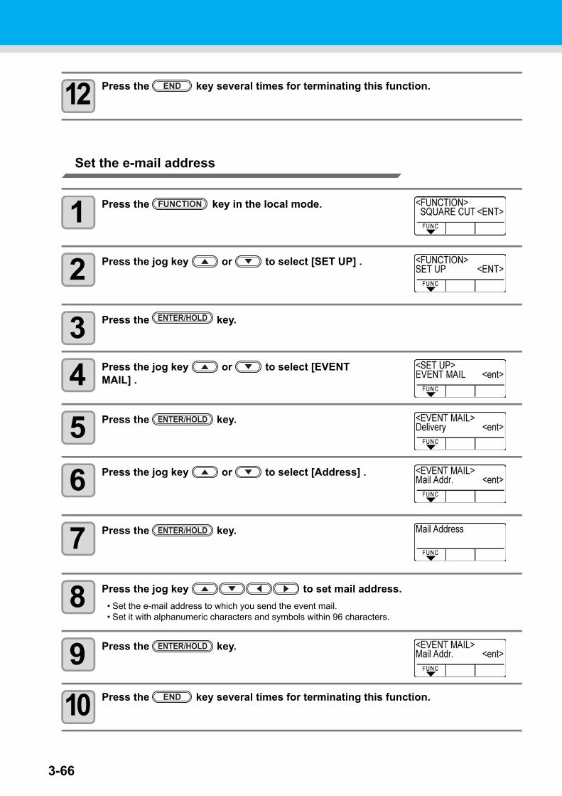
3-66
12 Press the key several times for terminating this function.
Set the e-mail address
1 Press the key in the local mode.
2 Press the jog key or to select [SET UP] .
3 Press the key.
4 Press the jog key or to select [EVENT MAIL] .
5 Press the key.
6 Press the jog key or to select [Address] .
7 Press the key.
8 Press the jog key to set mail address.
• Set the e-mail address to which you send the event mail.• Set it with alphanumeric characters and symbols within 96 characters.
9 Press the key.
10 Press the key several times for terminating this function.
END
FUNCTION
ENTER/HOLD
ENTER/HOLD
ENTER/HOLD
ENTER/HOLD
END
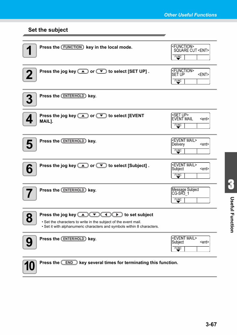
Other Useful Functions
1
1
3
Usefu
l Fu
nctio
n
5
63-67
Set the subject
1 Press the key in the local mode.
2 Press the jog key or to select [SET UP] .
3 Press the key.
4 Press the jog key or to select [EVENT MAIL].
5 Press the key.
6 Press the jog key or to select [Subject] .
7 Press the key.
8 Press the jog key to set subject
• Set the characters to write in the subject of the event mail.• Set it with alphanumeric characters and symbols within 8 characters.
9 Press the key.
10 Press the key several times for terminating this function.
FUNCTION
ENTER/HOLD
ENTER/HOLD
ENTER/HOLD
ENTER/HOLD
END
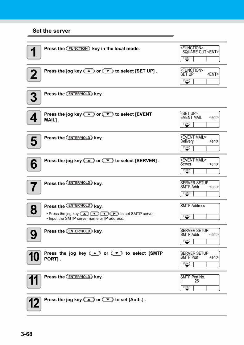
3-68
Set the server
1 Press the key in the local mode.
2 Press the jog key or to select [SET UP] .
3 Press the key.
4 Press the jog key or to select [EVENT MAIL] .
5 Press the key.
6 Press the jog key or to select [SERVER] .
7 Press the key.
8 Press the key.
• Press the jog key to set SMTP server.• Input the SMTP server name or IP address.
9 Press the key.
10 Press the jog key or to select [SMTPPORT] .
11 Press the key.
12 Press the jog key or to set [Auth.] .
FUNCTION
ENTER/HOLD
ENTER/HOLD
ENTER/HOLD
ENTER/HOLD
ENTER/HOLD
ENTER/HOLD
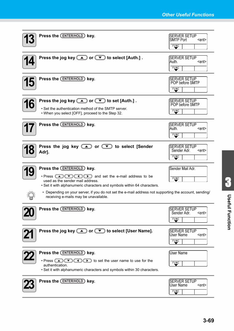
Other Useful Functions
1
1
3
Usefu
l Fu
nctio
n
5
63-69
13 Press the key.
14 Press the jog key or to select [Auth.] .
15 Press the key.
16 Press the jog key or to set [Auth.] .
• Set the authentication method of the SMTP server.• When you select [OFF], proceed to the Step 32.
17 Press the key.
18 Press the jog key or to select [SenderAdr].
19 Press the key.
• Press and set the e-mail address to beused as the sender mail address.
• Set it with alphanumeric characters and symbols within 64 characters.
20 Press the key.
21 Press the jog key or to select [User Name].
22 Press the key.
• Press to set the user name to use for theauthentication.
• Set it with alphanumeric characters and symbols within 30 characters.
23 Press the key.
• Depending on your server, if you do not set the e-mail address not supporting the account, sending/ receiving e-mails may be unavailable.
ENTER/HOLD
ENTER/HOLD
ENTER/HOLD
ENTER/HOLD
ENTER/HOLD
ENTER/HOLD
ENTER/HOLD
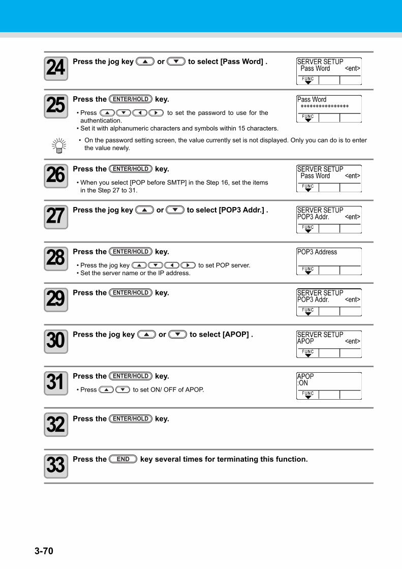
3-70
24 Press the jog key or to select [Pass Word] .
25 Press the key.
• Press to set the password to use for theauthentication.
• Set it with alphanumeric characters and symbols within 15 characters.
26 Press the key.
• When you select [POP before SMTP] in the Step 16, set the itemsin the Step 27 to 31.
27 Press the jog key or to select [POP3 Addr.] .
28 Press the key.
• Press the jog key to set POP server.• Set the server name or the IP address.
29 Press the key.
30 Press the jog key or to select [APOP] .
31 Press the key.
• Press to set ON/ OFF of APOP.
32 Press the key.
33 Press the key several times for terminating this function.
• On the password setting screen, the value currently set is not displayed. Only you can do is to enter the value newly.
ENTER/HOLD
ENTER/HOLD
ENTER/HOLD
ENTER/HOLD
ENTER/HOLD
ENTER/HOLD
END
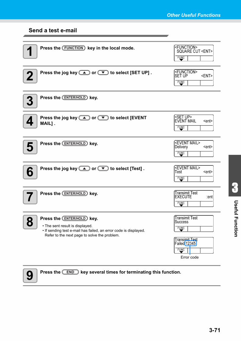
Other Useful Functions
1
1
3
Usefu
l Fu
nctio
n
5
63-71
Send a test e-mail
1 Press the key in the local mode.
2 Press the jog key or to select [SET UP] .
3 Press the key.
4 Press the jog key or to select [EVENT MAIL] .
5 Press the key.
6 Press the jog key or to select [Test] .
7 Press the key.
8 Press the key.
• The sent result is displayed.• If sending test e-mail has failed, an error code is displayed.
Refer to the next page to solve the problem.
9 Press the key several times for terminating this function.
FUNCTION
ENTER/HOLD
ENTER/HOLD
ENTER/HOLD
Error code
ENTER/HOLD
END
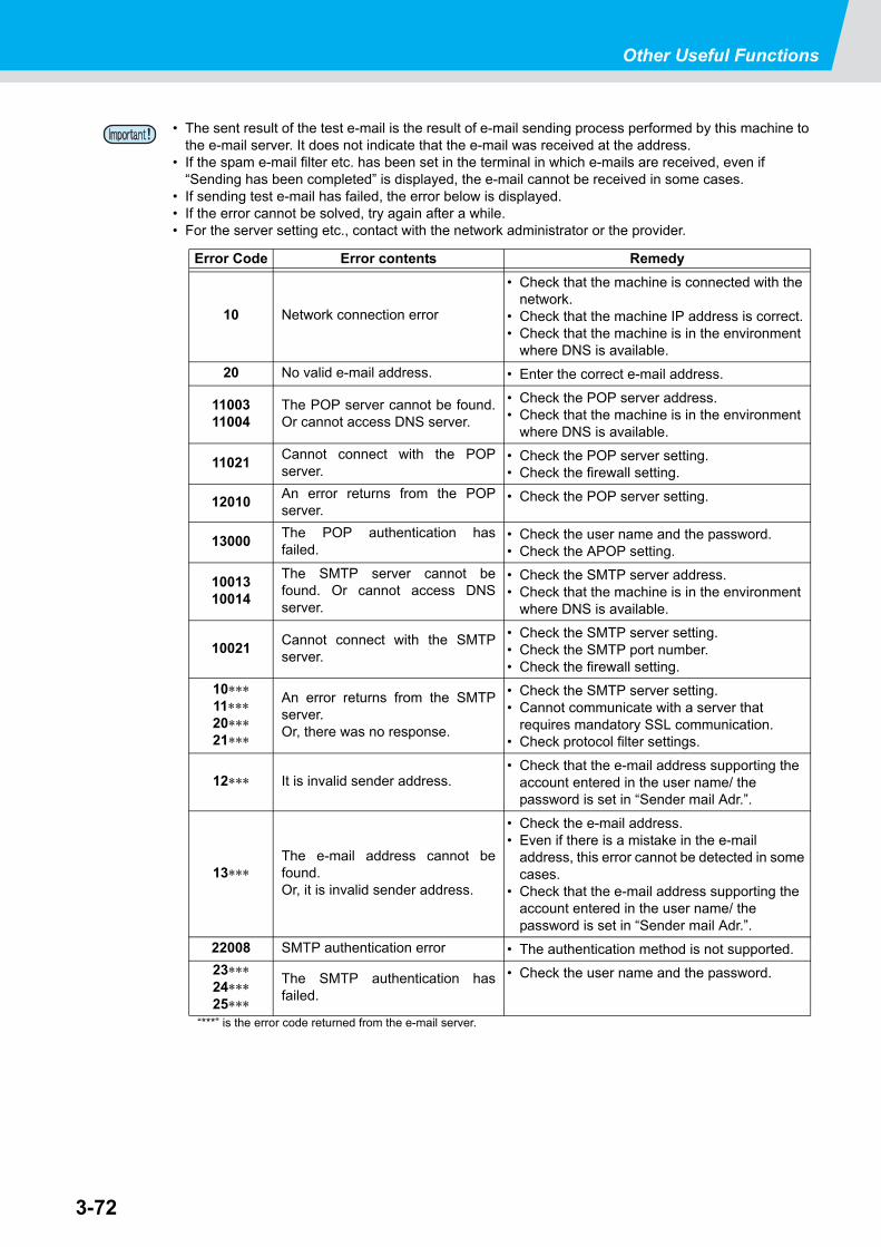
Other Useful Functions
3-72
• The sent result of the test e-mail is the result of e-mail sending process performed by this machine to the e-mail server. It does not indicate that the e-mail was received at the address.
• If the spam e-mail filter etc. has been set in the terminal in which e-mails are received, even if “Sending has been completed” is displayed, the e-mail cannot be received in some cases.
• If sending test e-mail has failed, the error below is displayed.• If the error cannot be solved, try again after a while.• For the server setting etc., contact with the network administrator or the provider.
“***” is the error code returned from the e-mail server.
Error Code Error contents Remedy
10 Network connection error
• Check that the machine is connected with the network.
• Check that the machine IP address is correct.• Check that the machine is in the environment
where DNS is available.
20 No valid e-mail address. • Enter the correct e-mail address.
1100311004
The POP server cannot be found.Or cannot access DNS server.
• Check the POP server address.• Check that the machine is in the environment
where DNS is available.
11021Cannot connect with the POPserver.
• Check the POP server setting.• Check the firewall setting.
12010An error returns from the POPserver.
• Check the POP server setting.
13000The POP authentication hasfailed.
• Check the user name and the password.• Check the APOP setting.
1001310014
The SMTP server cannot befound. Or cannot access DNSserver.
• Check the SMTP server address.• Check that the machine is in the environment
where DNS is available.
10021Cannot connect with the SMTPserver.
• Check the SMTP server setting.• Check the SMTP port number.• Check the firewall setting.
10∗∗∗11∗∗∗20∗∗∗21∗∗∗
An error returns from the SMTPserver.Or, there was no response.
• Check the SMTP server setting.• Cannot communicate with a server that
requires mandatory SSL communication.• Check protocol filter settings.
12∗∗∗ It is invalid sender address.• Check that the e-mail address supporting the
account entered in the user name/ the password is set in “Sender mail Adr.”.
13∗∗∗The e-mail address cannot befound.Or, it is invalid sender address.
• Check the e-mail address.• Even if there is a mistake in the e-mail
address, this error cannot be detected in some cases.
• Check that the e-mail address supporting the account entered in the user name/ the password is set in “Sender mail Adr.”.
22008 SMTP authentication error • The authentication method is not supported.
23∗∗∗24∗∗∗25∗∗∗
The SMTP authentication hasfailed.
• Check the user name and the password.
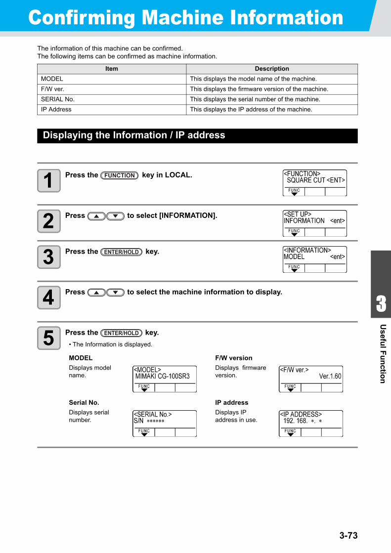
3-73
1
1
3
Usefu
l Fu
nctio
n
5
6
Confirming Machine InformationThe information of this machine can be confirmed.The following items can be confirmed as machine information.
Displaying the Information / IP address
1 Press the key in LOCAL.
2 Press to select [INFORMATION].
3 Press the key.
4 Press to select the machine information to display.
5 Press the key.
• The Information is displayed.
Item Description
MODEL This displays the model name of the machine.
F/W ver. This displays the firmware version of the machine.
SERIAL No. This displays the serial number of the machine.
IP Address This displays the IP address of the machine.
MODEL
Displays model name.
F/W version
Displays firmwareversion.
Serial No.
Displays serial number.
IP address
Displays IP address in use.
FUNCTION
ENTER/HOLD
ENTER/HOLD
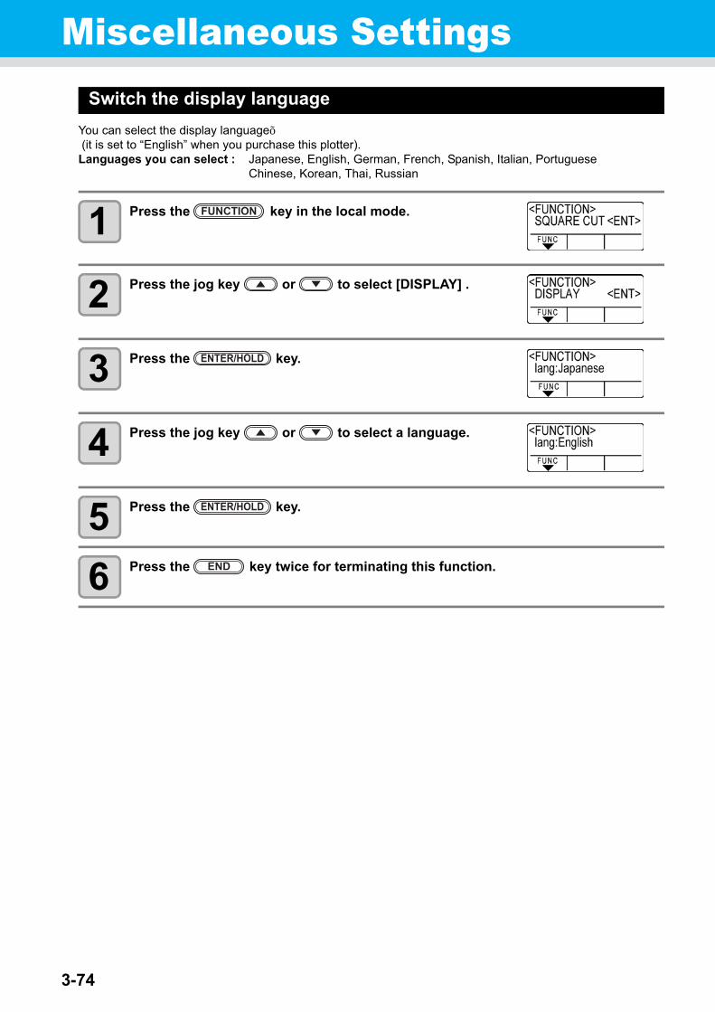
3-74
Miscellaneous SettingsSwitch the display language
You can select the display language. (it is set to “English” when you purchase this plotter).Languages you can select : Japanese, English, German, French, Spanish, Italian, Portuguese
Chinese, Korean, Thai, Russian
1 Press the key in the local mode.
2 Press the jog key or to select [DISPLAY] .
3 Press the key.
4 Press the jog key or to select a language.
5 Press the key.
6 Press the key twice for terminating this function.
FUNCTION
ENTER/HOLD
ENTER/HOLD
END
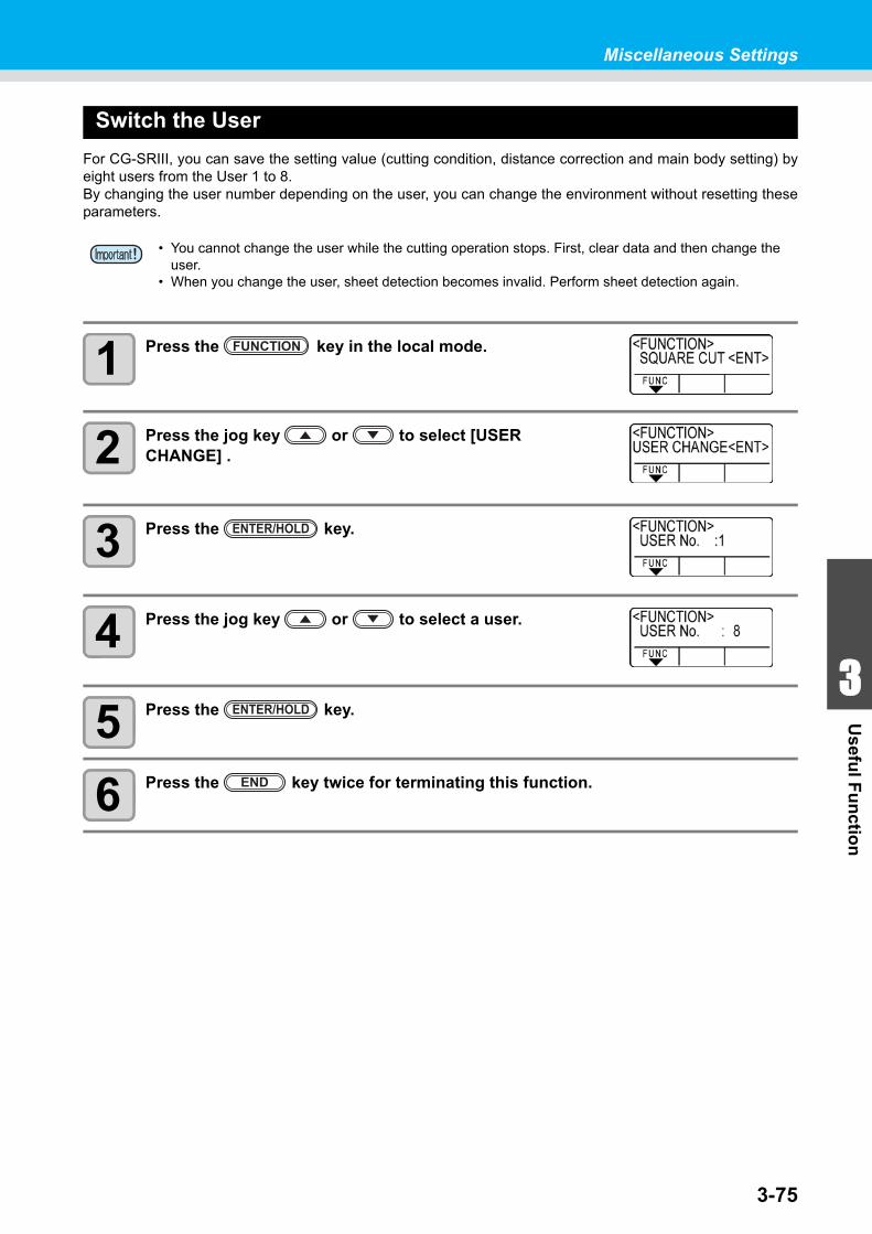
3-75
1
1
3
Usefu
l Fu
nctio
n
5
6
Miscellaneous Settings
Switch the User
For CG-SRIII, you can save the setting value (cutting condition, distance correction and main body setting) byeight users from the User 1 to 8.By changing the user number depending on the user, you can change the environment without resetting theseparameters.
1 Press the key in the local mode.
2 Press the jog key or to select [USER CHANGE] .
3 Press the key.
4 Press the jog key or to select a user.
5 Press the key.
6 Press the key twice for terminating this function.
• You cannot change the user while the cutting operation stops. First, clear data and then change the user.
• When you change the user, sheet detection becomes invalid. Perform sheet detection again.
FUNCTION
ENTER/HOLD
ENTER/HOLD
END
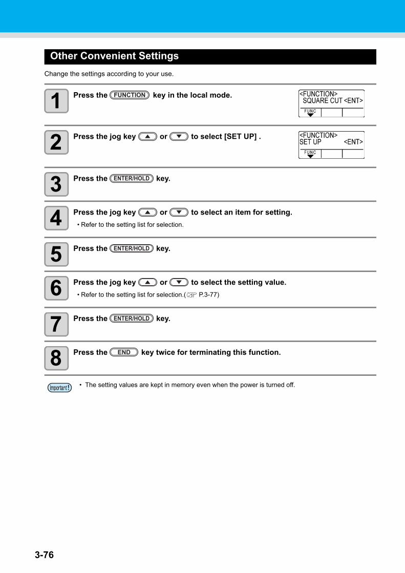
3-76
Other Convenient Settings
Change the settings according to your use.
1 Press the key in the local mode.
2 Press the jog key or to select [SET UP] .
3 Press the key.
4 Press the jog key or to select an item for setting.
• Refer to the setting list for selection.
5 Press the key.
6 Press the jog key or to select the setting value.
• Refer to the setting list for selection.( P.3-77)
7 Press the key.
8 Press the key twice for terminating this function.
• The setting values are kept in memory even when the power is turned off.
FUNCTION
ENTER/HOLD
ENTER/HOLD
ENTER/HOLD
END
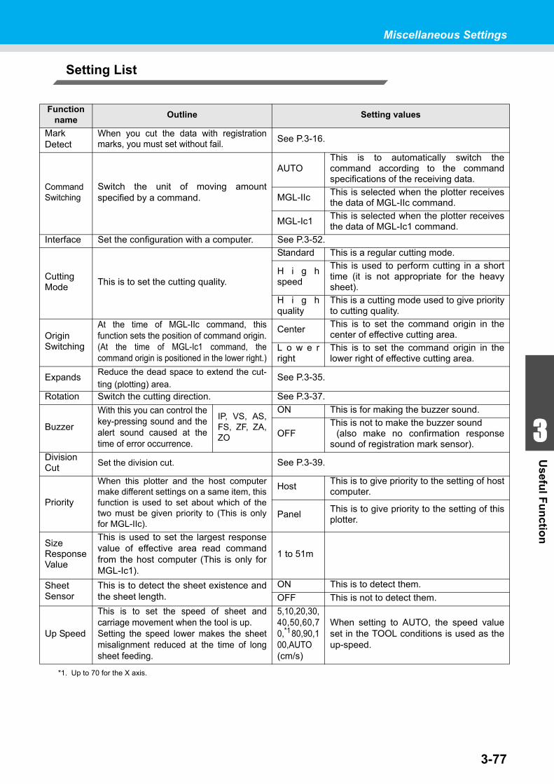
3-77
1
1
3
Usefu
l Fu
nctio
n
5
6
Miscellaneous Settings
Setting List
Function name
Outline Setting values
Mark Detect
When you cut the data with registrationmarks, you must set without fail.
See P.3-16.
CommandSwitching
Switch the unit of moving amountspecified by a command.
AUTOThis is to automatically switch thecommand according to the commandspecifications of the receiving data.
MGL-IIcThis is selected when the plotter receivesthe data of MGL-IIc command.
MGL-Ic1This is selected when the plotter receivesthe data of MGL-Ic1 command.
Interface Set the configuration with a computer. See P.3-52.
CuttingMode
This is to set the cutting quality.
Standard This is a regular cutting mode.
H i g hspeed
This is used to perform cutting in a shorttime (it is not appropriate for the heavysheet).
H i g hquality
This is a cutting mode used to give priorityto cutting quality.
OriginSwitching
At the time of MGL-IIc command, thisfunction sets the position of command origin.(At the time of MGL-Ic1 command, thecommand origin is positioned in the lower right.)
CenterThis is to set the command origin in thecenter of effective cutting area.
L o w e rright
This is to set the command origin in thelower right of effective cutting area.
ExpandsReduce the dead space to extend the cut-
ting (plotting) area.See P.3-35.
Rotation Switch the cutting direction. See P.3-37.
Buzzer
With this you can control thekey-pressing sound and thealert sound caused at thetime of error occurrence.
IP, VS, AS,FS, ZF, ZA,ZO
ON This is for making the buzzer sound.
OFFThis is not to make the buzzer sound (also make no confirmation responsesound of registration mark sensor).
DivisionCut
Set the division cut. See P.3-39.
Priority
When this plotter and the host computermake different settings on a same item, thisfunction is used to set about which of thetwo must be given priority to (This is onlyfor MGL-IIc).
HostThis is to give priority to the setting of hostcomputer.
PanelThis is to give priority to the setting of thisplotter.
SizeResponseValue
This is used to set the largest responsevalue of effective area read commandfrom the host computer (This is only forMGL-Ic1).
1 to 51m
SheetSensor
This is to detect the sheet existence andthe sheet length.
ON This is to detect them.
OFF This is not to detect them.
Up Speed
This is to set the speed of sheet andcarriage movement when the tool is up. Setting the speed lower makes the sheetmisalignment reduced at the time of longsheet feeding.
5,10,20,30,40,50,60,70,*180,90,100,AUTO(cm/s)
*1. Up to 70 for the X axis.
When setting to AUTO, the speed valueset in the TOOL conditions is used as theup-speed.
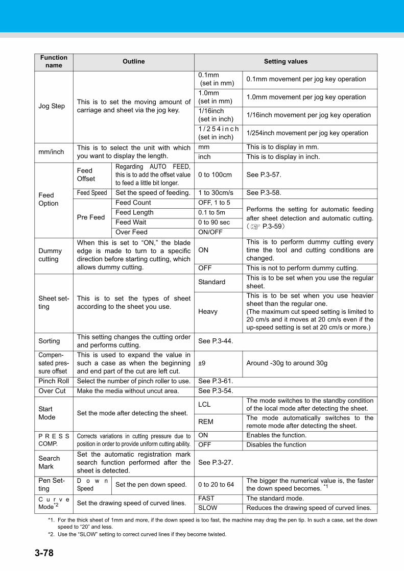
3-78
Function name
Outline Setting values
Jog StepThis is to set the moving amount ofcarriage and sheet via the jog key.
0.1mm (set in mm)
0.1mm movement per jog key operation
1.0mm (set in mm)
1.0mm movement per jog key operation
1/16inch(set in inch)
1/16inch movement per jog key operation
1 / 2 5 4 i n c h(set in inch)
1/254inch movement per jog key operation
mm/inchThis is to select the unit with whichyou want to display the length.
mm This is to display in mm.
inch This is to display in inch.
Feed Option
Feed Offset
Regarding AUTO FEED,this is to add the offset valueto feed a little bit longer.
0 to 100cm See P.3-57.
Feed Speed Set the speed of feeding. 1 to 30cm/s See P.3-58.
Pre Feed
Feed Count OFF, 1 to 5Performs the setting for automatic feeding
after sheet detection and automatic cutting.( P.3-59)
Feed Length 0.1 to 5m
Feed Wait 0 to 90 sec
Over Feed ON/OFF
Dummy cutting
When this is set to “ON,” the bladeedge is made to turn to a specificdirection before starting cutting, whichallows dummy cutting.
ONThis is to perform dummy cutting everytime the tool and cutting conditions arechanged.
OFF This is not to perform dummy cutting.
Sheet set-ting
This is to set the types of sheetaccording to the sheet you use.
StandardThis is to be set when you use the regularsheet.
Heavy
This is to be set when you use heaviersheet than the regular one.(The maximum cut speed setting is limited to20 cm/s and it moves at 20 cm/s even if theup-speed setting is set at 20 cm/s or more.)
SortingThis setting changes the cutting orderand performs cutting.
See P.3-44.
Compen-sated pres-sure offset
This is used to expand the value insuch a case as when the beginningand end part of the cut are left cut.
±9 Around -30g to around 30g
Pinch Roll Select the number of pinch roller to use. See P.3-61.
Over Cut Make the media without uncut area. See P.3-54.
Start Mode
Set the mode after detecting the sheet.LCL
The mode switches to the standby conditionof the local mode after detecting the sheet.
REMThe mode automatically switches to theremote mode after detecting the sheet.
P R E S SCOMP.
Corrects variations in cutting pressure due toposition in order to provide uniform cutting ability.
ON Enables the function.
OFF Disables the function
Search Mark
Set the automatic registration marksearch function performed after thesheet is detected.
See P.3-27.
Pen Set-ting
D o w nSpeed
Set the pen down speed. 0 to 20 to 64The bigger the numerical value is, the fasterthe down speed becomes. *1
*1. For the thick sheet of 1mm and more, if the down speed is too fast, the machine may drag the pen tip. In such a case, set the downspeed to “20” and less.
C u r v eMode*2
*2. Use the “SLOW” setting to correct curved lines if they become twisted.
Set the drawing speed of curved lines.FAST The standard mode.
SLOW Reduces the drawing speed of curved lines.
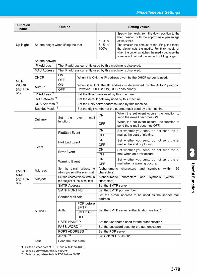
3-79
1
1
3
Usefu
l Fu
nctio
n
5
6
Miscellaneous Settings
Function name
Outline Setting values
Up Hight Set the height when lifting the tool5 0 % ,7 5 % ,100%
Specify the height from the down position to thelifted position, with the approximate percentageof the stroke.The smaller the amount of the lifting, the fasterthe plotter cuts the media. For thick media orwhen the cutter scratches the media because thesheet is not flat, set the amount of lifting bigger.
NET-WORK( P.3-61)
Set the network.
IP Address The IP address currently used by this machine is displayed.
MAC Address The IP address currently used by this machine is displayed.
DHCPON
When it is ON, the IP address given by the DHCP server is used.OFF
AutoIPON When it is ON, the IP address is determined by the AutoIP protocol.
However, DHCP is ON, DHCP has priority.OFF
IP Address *1 Set the IP address used by this machine.
Def.Gateway *1 Set the default gateway used by this machine.
DNS Address *1 Set the DNS server address used by this machine.
SubNet Mask *1 Set the digit number of the subnet mask used by this machine.
EVENT MAIL( P.3-63)
DeliverySet the event mailfunction.
ONWhen the set event occurs, the function tosend the e-mail becomes ON.
OFFWhen the set event occurs, the function tosend the e-mail becomes OFF.
Event
PlotStart EventON Set whether you send/ do not send the e-
mail at the start of plotting.OFF
Plot End EventON Set whether you send/ do not send the e-
mail at the end of plotting.OFF
Error EventON Set whether you send/ do not send the e-
mail when an error occurs.OFF
Warning EventON Set whether you send/ do not send the e-
mail when a warning occurs.OFF
AddressSet the e-mail address towhich you send the event mail.
Alphanumeric characters and symbols (within 96characters)
SubjectSet the characters to write inthe subject of the event mail.
Alphanumeric characters and symbols (within 8characters)
SERVER
SMTP Address Set the SMTP server.
SMTP PORT No. Set the SMTP port number.
Sender Mail Adr.Set the e-mail address to be used as the sender mailaddress.
Auth.
POP beforeSMTP
Set the SMTP server authentication method.SMTP Auth
OFF
USER NAME *2 Set the user name used for the authentication.
PASS WORD *2 Set the password used for the authentication.
POP3 ADDRESS *3 Set the POP server.
APOP *3 Set ON/ OFF of APOP.
Test Send the test e-mail.
*1. Settable when both of DHCP and AutoIP are [OFF]*2. Settable only when Auth. is not OFF*3. Settable only when Auth. is POP before SMTP

3-80
Function name
Outline Setting values
Seteup Reset
Copy the set value to other user setting. See P.3-84.
Seteup Reset
Reset the setting values to the initialstate.
See P.3-85.
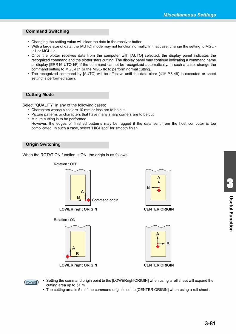
3-81
1
1
3
Usefu
l Fu
nctio
n
5
6
Miscellaneous Settings
Command Switching
• Changing the setting value will clear the data in the receiver buffer.• With a large size of data, the [AUTO] mode may not function normally. In that case, change the setting to MGL -
Ic1 or MGL-IIc.• Once the plotter receives data from the computer with [AUTO] selected, the display panel indicates the
recognized command and the plotter stars cutting. The display panel may continue indicating a command nameor display [ERR16 UTO I/F] if the command cannot be recognized automatically. In such a case, change thecommand setting to MGL-I c1 or the MGL- IIc to perform normal cutting.
• The recognized command by [AUTO] will be effective until the data clear ( P.3-48) is executed or sheetsetting is performed again.
Cutting Mode
Select “QUALITY” in any of the following cases:• Characters whose sizes are 10 mm or less are to be cut• Picture patterns or characters that have many sharp corners are to be cut• Minute cutting is to be performed
However, the edges of finished patterns may be rugged if the data sent from the host computer is toocomplicated. In such a case, select “HIGHspd” for smooth finish.
Origin Switching
When the ROTATION function is ON, the origin is as follows:
• Setting the command origin point to the [LOWERrightORIGIN] when using a roll sheet will expand the cutting area up to 51 m.
• The cutting area is 5 m if the command origin is set to [CENTER ORIGIN] when using a roll sheet .
Rotation : OFF
Rotation : ON
LOWER right ORIGIN CENTER ORIGIN
Command origin
LOWER right ORIGIN CENTER ORIGIN
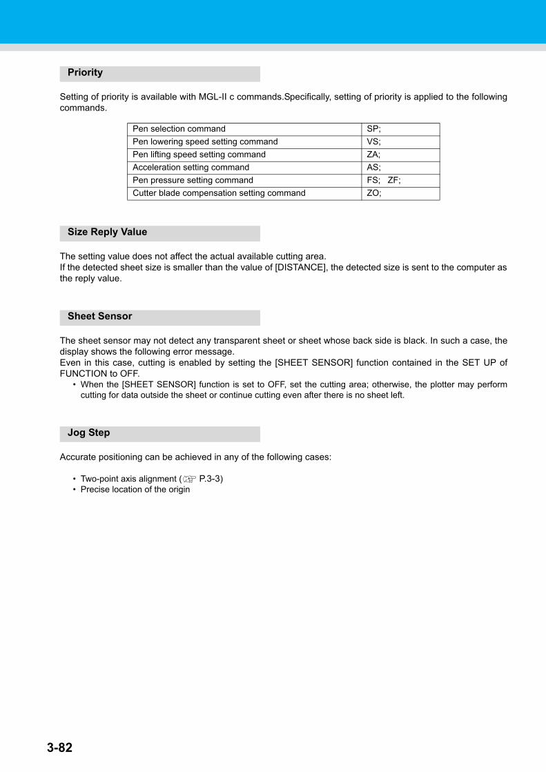
3-82
Priority
Setting of priority is available with MGL-II c commands.Specifically, setting of priority is applied to the followingcommands.
Size Reply Value
The setting value does not affect the actual available cutting area.If the detected sheet size is smaller than the value of [DISTANCE], the detected size is sent to the computer asthe reply value.
Sheet Sensor
The sheet sensor may not detect any transparent sheet or sheet whose back side is black. In such a case, thedisplay shows the following error message.Even in this case, cutting is enabled by setting the [SHEET SENSOR] function contained in the SET UP ofFUNCTION to OFF.
• When the [SHEET SENSOR] function is set to OFF, set the cutting area; otherwise, the plotter may performcutting for data outside the sheet or continue cutting even after there is no sheet left.
Jog Step
Accurate positioning can be achieved in any of the following cases:
• Two-point axis alignment ( P.3-3)• Precise location of the origin
Pen selection command SP;
Pen lowering speed setting command VS;
Pen lifting speed setting command ZA;
Acceleration setting command AS;
Pen pressure setting command FS; ZF;
Cutter blade compensation setting command ZO;
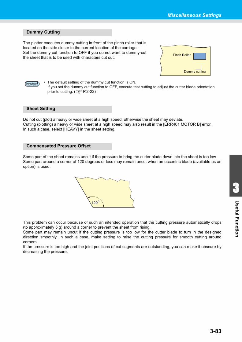
3-83
1
1
3
Usefu
l Fu
nctio
n
5
6
Miscellaneous Settings
Dummy Cutting
The plotter executes dummy cutting in front of the pinch roller that islocated on the side closer to the current location of the carriage.Set the dummy cut function to OFF if you do not want to dummy-cutthe sheet that is to be used with characters cut out.
Sheet Setting
Do not cut (plot) a heavy or wide sheet at a high speed; otherwise the sheet may deviate.Cutting (plotting) a heavy or wide sheet at a high speed may also result in the [ERR401 MOTOR B] error.In such a case, select [HEAVY] in the sheet setting.
Compensated Pressure Offset
Some part of the sheet remains uncut if the pressure to bring the cutter blade down into the sheet is too low.Some part around a corner of 120 degrees or less may remain uncut when an eccentric blade (available as anoption) is used.
This problem can occur because of such an intended operation that the cutting pressure automatically drops(to approximately 5 g) around a corner to prevent the sheet from rising.Some part may remain uncut if the cutting pressure is too low for the cutter blade to turn in the designeddirection smoothly. In such a case, make setting to raise the cutting pressure for smooth cutting aroundcorners.If the pressure is too high and the joint positions of cut segments are outstanding, you can make it obscure bydecreasing the pressure.
• The default setting of the dummy cut function is ON.If you set the dummy cut function to OFF, execute test cutting to adjust the cutter blade orientation prior to cutting. ( P.2-22)
Pinch Roller
Dummy cutting
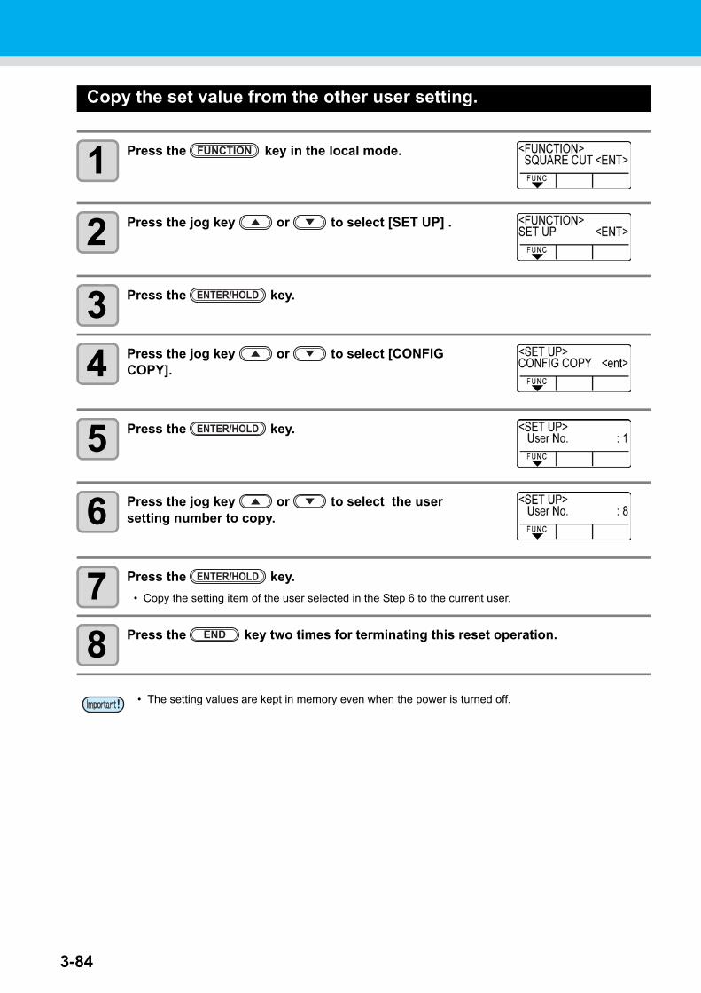
3-84
Copy the set value from the other user setting.
1 Press the key in the local mode.
2 Press the jog key or to select [SET UP] .
3 Press the key.
4 Press the jog key or to select [CONFIG COPY].
5 Press the key.
6 Press the jog key or to select the user setting number to copy.
7 Press the key.
• Copy the setting item of the user selected in the Step 6 to the current user.
8 Press the key two times for terminating this reset operation.
• The setting values are kept in memory even when the power is turned off.
FUNCTION
ENTER/HOLD
ENTER/HOLD
ENTER/HOLD
END
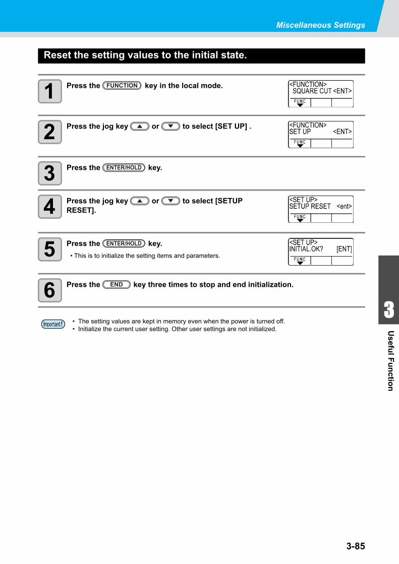
3-85
1
1
3
Usefu
l Fu
nctio
n
5
6
Miscellaneous Settings
Reset the setting values to the initial state.
1 Press the key in the local mode.
2 Press the jog key or to select [SET UP] .
3 Press the key.
4 Press the jog key or to select [SETUP RESET].
5 Press the key.
• This is to initialize the setting items and parameters.
6 Press the key three times to stop and end initialization.
• The setting values are kept in memory even when the power is turned off.• Initialize the current user setting. Other user settings are not initialized.
FUNCTION
ENTER/HOLD
ENTER/HOLD
END

3-86
This chapter describes the actions to be taken when the plotterdevelops any trouble or displays an error message.
Before taking a phenomenon as a trouble ........................ 4-2Troubles for which error messages are given on the LCD... 4-4
Error message ............................................................................4-4Status message ..........................................................................4-7
CHAPTER 4
In Case of Trouble
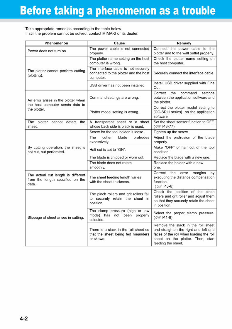
4-2
Before taking a phenomenon as a troubleTake appropriate remedies according to the table below.If still the problem cannot be solved, contact MIMAKI or its dealer.
Phenomenon Cause Remedy
Power does not turn on.The power cable is not connectedproperly.
Connect the power cable to theplotter and to the wall outlet properly.
The plotter cannot perform cutting(plotting).
The plotter name setting on the hostcomputer is wrong.
Check the plotter name setting onthe host computer.
The interface cable is not securelyconnected to the plotter and the hostcomputer.
Securely connect the interface cable.
USB driver has not been installed.Install USB driver supplied with FineCut.
An error arises in the plotter whenthe host computer sends data tothe plotter.
Command settings are wrong.Correct the command settingsbetween the application software andthe plotter.
Plotter model setting is wrong.Correct the plotter model setting to[CG-SRIII series] on the applicationsoftware.
The plotter cannot detect thesheet.
A transparent sheet or a sheetwhose back side is black is used.
Set the sheet sensor function to OFF.( P.3-77)
By cutting operation, the sheet isnot cut, but perforated.
Screw for the tool holder is loose. Tighten up the screw.
The cutter blade protrudesexcessively.
Adjust the protrusion of the bladeproperly.
Half cut is set to “ON”.Make “OFF” of half cut of the toolcondition.
The blade is chipped or worn out. Replace the blade with a new one.
The blade does not rotatesmoothly.
Replace the holder with a newone.
The actual cut length is differentfrom the length specified on thedata.
The sheet feeding length varieswith the sheet thickness.
Correct the error margins byexecuting the distance compensationfunction. ( P.3-6)
Slippage of sheet arises in cutting.
The pinch rollers and grit rollers failto securely retain the sheet inposition.
Check the position of the pinchrollers and grit roller and adjust themso that they securely retain the sheetin position.
The clamp pressure (high or lowmode) has not been properlyselected.
Select the proper clamp pressure.( P.1-8)
There is a slack in the roll sheet sothat the sheet being fed meandersor skews.
Remove the slack in the roll sheetand straighten the right and left endfaces of the roll when loading the rollsheet on the plotter. Then, startfeeding the sheet.
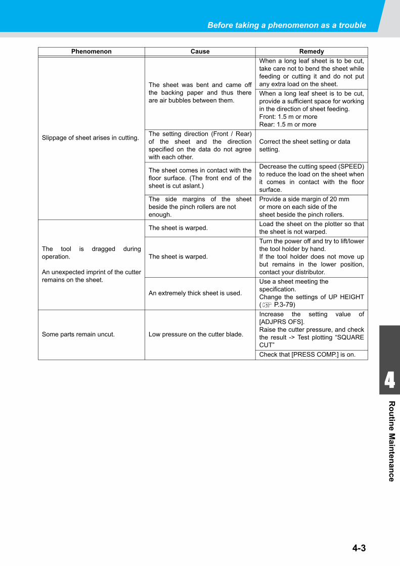
Before taking a phenomenon as a trouble
4-3
1
1
1
4
Ro
utin
e Main
tenan
ce
Phenomenon Cause Remedy
Slippage of sheet arises in cutting.
The sheet was bent and came offthe backing paper and thus thereare air bubbles between them.
When a long leaf sheet is to be cut,take care not to bend the sheet whilefeeding or cutting it and do not putany extra load on the sheet.
When a long leaf sheet is to be cut,provide a sufficient space for workingin the direction of sheet feeding. Front: 1.5 m or moreRear: 1.5 m or more
The setting direction (Front / Rear)of the sheet and the directionspecified on the data do not agreewith each other.
Correct the sheet setting or datasetting.
The sheet comes in contact with thefloor surface. (The front end of thesheet is cut aslant.)
Decrease the cutting speed (SPEED)to reduce the load on the sheet whenit comes in contact with the floorsurface.
The side margins of the sheetbeside the pinch rollers are notenough.
Provide a side margin of 20 mmor more on each side of thesheet beside the pinch rollers.
The tool is dragged duringoperation.
An unexpected imprint of the cutterremains on the sheet.
The sheet is warped.Load the sheet on the plotter so thatthe sheet is not warped.
The sheet is warped.
Turn the power off and try to lift/lowerthe tool holder by hand.If the tool holder does not move upbut remains in the lower position,contact your distributor.
An extremely thick sheet is used.
Use a sheet meeting the specification.Change the settings of UP HEIGHT( P.3-79)
Some parts remain uncut. Low pressure on the cutter blade.
Increase the setting value of[ADJPRS OFS].Raise the cutter pressure, and checkthe result -> Test plotting “SQUARECUT”
Check that [PRESS COMP.] is on.
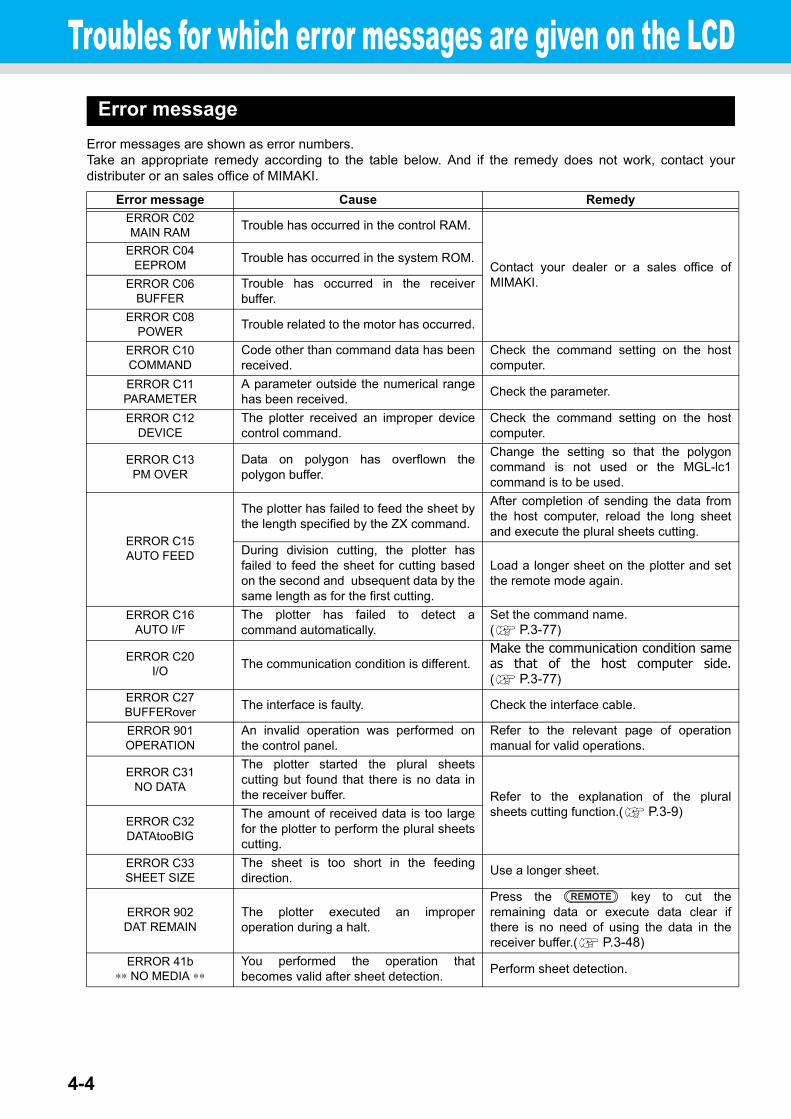
4-4
Troubles for which error messages are given on the LCDError message
Error messages are shown as error numbers.Take an appropriate remedy according to the table below. And if the remedy does not work, contact yourdistributer or an sales office of MIMAKI.
Error message Cause Remedy
ERROR C02MAIN RAM
Trouble has occurred in the control RAM.
Contact your dealer or a sales office ofMIMAKI.
ERROR C04EEPROM
Trouble has occurred in the system ROM.
ERROR C06BUFFER
Trouble has occurred in the receiverbuffer.
ERROR C08POWER
Trouble related to the motor has occurred.
ERROR C10COMMAND
Code other than command data has beenreceived.
Check the command setting on the hostcomputer.
ERROR C11PARAMETER
A parameter outside the numerical rangehas been received.
Check the parameter.
ERROR C12DEVICE
The plotter received an improper devicecontrol command.
Check the command setting on the hostcomputer.
ERROR C13PM OVER
Data on polygon has overflown thepolygon buffer.
Change the setting so that the polygoncommand is not used or the MGL-lc1command is to be used.
ERROR C15AUTO FEED
The plotter has failed to feed the sheet bythe length specified by the ZX command.
After completion of sending the data fromthe host computer, reload the long sheetand execute the plural sheets cutting.
During division cutting, the plotter hasfailed to feed the sheet for cutting basedon the second and ubsequent data by thesame length as for the first cutting.
Load a longer sheet on the plotter and setthe remote mode again.
ERROR C16AUTO I/F
The plotter has failed to detect acommand automatically.
Set the command name.( P.3-77)
ERROR C20I/O
The communication condition is different.Make the communication condition sameas that of the host computer side.( P.3-77)
ERROR C27BUFFERover
The interface is faulty. Check the interface cable.
ERROR 901OPERATION
An invalid operation was performed onthe control panel.
Refer to the relevant page of operationmanual for valid operations.
ERROR C31NO DATA
The plotter started the plural sheetscutting but found that there is no data inthe receiver buffer. Refer to the explanation of the plural
sheets cutting function.( P.3-9)ERROR C32DATAtooBIG
The amount of received data is too largefor the plotter to perform the plural sheetscutting.
ERROR C33SHEET SIZE
The sheet is too short in the feedingdirection.
Use a longer sheet.
ERROR 902DAT REMAIN
The plotter executed an improperoperation during a halt.
Press the key to cut theremaining data or execute data clear ifthere is no need of using the data in thereceiver buffer.( P.3-48)
ERROR 41b∗∗ NO MEDIA ∗∗
You performed the operation thatbecomes valid after sheet detection.
Perform sheet detection.
REMOTE

Troubles for which error messages are given on the LCD
4-5
1
1
1
4
In C
ase of Tro
ub
le
Error message Cause Remedy
ERROR C36MARKdetect
No registration mark was detected.
Check the sheet for curling.
Check to see if the starting point to detectthe registration mark has been set properly.( P.3-21)
Check to see if the black registration markis printed against the white background.
Check to see if there is no dust or dirtbetween the registration marks.
Check to see if there is no mistake inregistration mark settings. ( P.3-16)
Confirm the status and the settingsdescribed above. If still no registrationmark is detected, contact your distributor ora sales office of MIMAKI.
Set the “MARK FILL UP” of registrationmark detection to “ON” when filled inaround the registration mark. ( P.3-20)
ERROR C37MARK ORG
The origin point was detected outside thecutting area.
Arrange the registration marks inside thesheet.
ERROR C38MARK SCALE
Registration mark detection was notachieved. However, this error isattributable to a false detection or acompensation value setting error, sincethe calculated compensation value iswrong.
Correct the compensation value if it iswrong, and perform detection again.
The required scale compensation valuewas not smaller than 1.3 times or notgreater than 0.7 times.
Remove the cause of the detection error,for example, correct the blurred print ofregistration mark data and then retry.
A detection error occurred since thedistance from the adjacent graphics wastoo short.
Increase the distance from the adjacentgraphics properly, and perform printingagain.
The designateed spacing between theregistration marks is not correct.
The value of the spacing between theregistration marks designated by thecommand is wrong and it is attributable to aselection error of data. Therefore, checkthe output data.
The print is not uniform and somegraphics are omitted.
Correct the graphic data to obtain uniformprint and perform printing again.
As the printed registration mark wasblurred, it was not read correctly and theregistration mark of the next graphics wasread by mistake.
Perform printing again with care that theprint is not blurred.
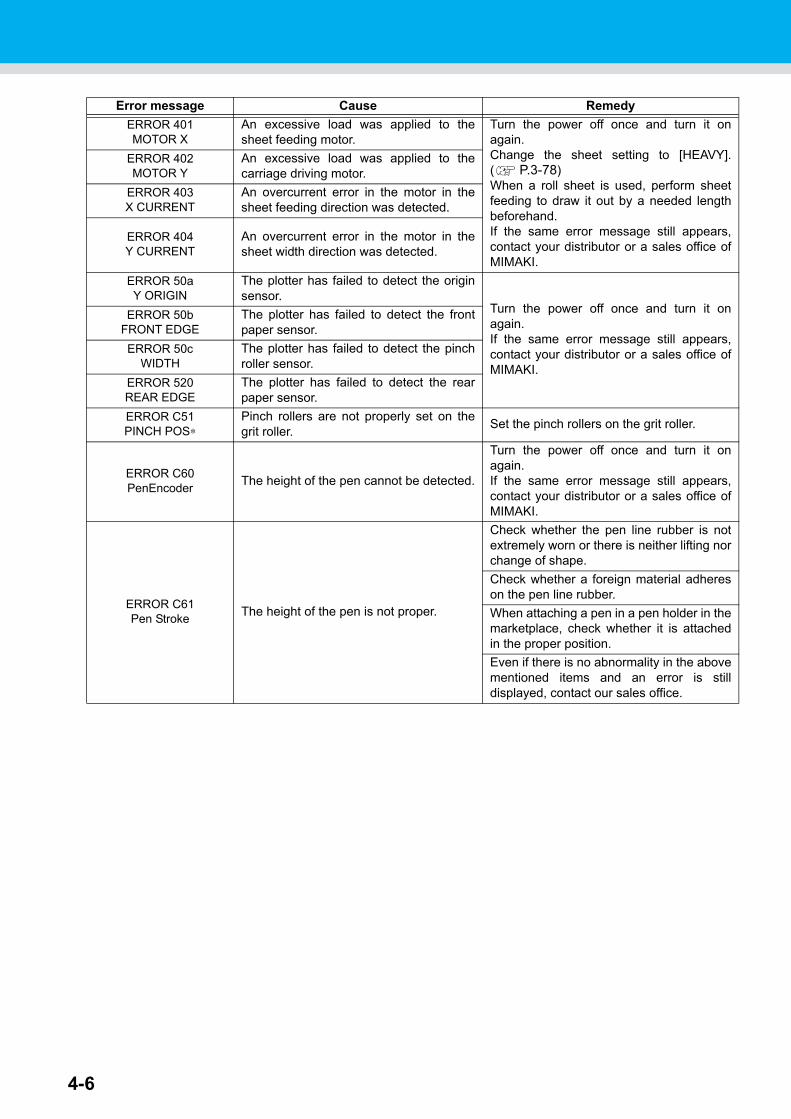
4-6
Error message Cause Remedy
ERROR 401MOTOR X
An excessive load was applied to thesheet feeding motor.
Turn the power off once and turn it onagain.Change the sheet setting to [HEAVY].( P.3-78)When a roll sheet is used, perform sheetfeeding to draw it out by a needed lengthbeforehand.If the same error message still appears,contact your distributor or a sales office ofMIMAKI.
ERROR 402MOTOR Y
An excessive load was applied to thecarriage driving motor.
ERROR 403X CURRENT
An overcurrent error in the motor in thesheet feeding direction was detected.
ERROR 404Y CURRENT
An overcurrent error in the motor in thesheet width direction was detected.
ERROR 50aY ORIGIN
The plotter has failed to detect the originsensor.
Turn the power off once and turn it onagain.If the same error message still appears,contact your distributor or a sales office ofMIMAKI.
ERROR 50bFRONT EDGE
The plotter has failed to detect the frontpaper sensor.
ERROR 50cWIDTH
The plotter has failed to detect the pinchroller sensor.
ERROR 520REAR EDGE
The plotter has failed to detect the rearpaper sensor.
ERROR C51PINCH POS∗
Pinch rollers are not properly set on thegrit roller.
Set the pinch rollers on the grit roller.
ERROR C60PenEncoder
The height of the pen cannot be detected.
Turn the power off once and turn it onagain.If the same error message still appears,contact your distributor or a sales office ofMIMAKI.
ERROR C61Pen Stroke
The height of the pen is not proper.
Check whether the pen line rubber is notextremely worn or there is neither lifting norchange of shape.
Check whether a foreign material adhereson the pen line rubber.
When attaching a pen in a pen holder in themarketplace, check whether it is attachedin the proper position.
Even if there is no abnormality in the abovementioned items and an error is stilldisplayed, contact our sales office.
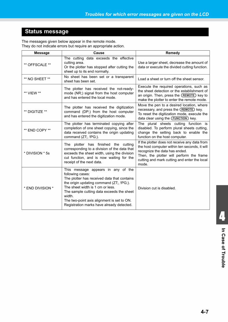
Troubles for which error messages are given on the LCD
4-7
1
1
1
4
In C
ase of Tro
ub
le
Status message
The messages given below appear in the remote mode.They do not indicate errors but require an appropriate action.
Message Cause Remedy
** OFFSCALE **
The cutting data exceeds the effectivecutting area.Or the plotter has stopped after cutting thesheet up to its end normally.
Use a larger sheet, decrease the amount ofdata or execute the divided cutting function.
** NO SHEET **No sheet has been set or a transparentsheet has been set.
Load a sheet or turn off the sheet sensor.
** VIEW **The plotter has received the not-ready-mode (NR;) signal from the host computerand has entered the local mode.
Execute the required operations, such asthe sheet detection or the establishment ofan origin. Then, press the key tomake the plotter to enter the remote mode.
** DIGITIZE **The plotter has received the digitizationcommand (DP;) from the host computerand has entered the digitization mode.
Move the pen to a desired location, wherenecessary, and press the key.To reset the digitization mode, execute thedata clear using the key.
** END COPY **
The plotter has terminated copying aftercompletion of one sheet copying, since thedata received contains the origin updatingcommand (ZT;, !PG;).
The plural sheets cutting function isdisabled. To perform plural sheets cutting,change the setting back to enable thefunction on the host computer.
* DIVISION * 5s
The plotter has finished the cuttingcorresponding to a division of the data thatexceeds the sheet width, using the divisioncut function, and is now waiting for thereceipt of the next data.
If the plotter does not receive any data fromthe host computer within ten seconds, it willrecognize the data has ended.Then, the plotter will perform the framecutting and mark cutting and enter the localmode.
* END DIVISION *
This message appears in any of thefollowing cases:The plotter has received data that containsthe origin updating command (ZT;, !PG;).The sheet width is 1 cm or less.The sample cutting data exceeds the sheetwidth.The two-point axis alignment is set to ON.Registration marks have already detected.
Division cut is disabled.
REMOTE
REMOTE
FUNCTION
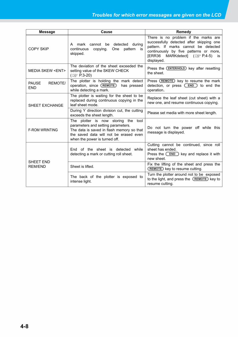
Troubles for which error messages are given on the LCD
4-8
Message Cause Remedy
COPY SKIPA mark cannot be detected duringcontinuous copying. One pattern isskipped.
There is no problem if the marks aresuccessfully detected after skipping onepattern. If marks cannot be detectedcontinuously by five patterns or more,[ERR36 MARKdetect] ( P.4-5) isdisplayed.
MEDIA SKEW <ENT>The deviation of the sheet exceeded thesetting value of the SKEW CHECK ( P.3-20)
Press the key after resettingthe sheet.
PAUSE REMOTE/END
The plotter is holding the mark detectoperation, since has pressedwhile detecting a mark.
Press key to resume the markdetection, or press to end theoperation.
SHEET EXCHANGE
The plotter is waiting for the sheet to bereplaced during continuous copying in theleaf sheet mode.
Replace the leaf sheet (cut sheet) with anew one, and resume continuous copying.
During Y direction division cut, the cuttingexceeds the sheet length.
Please set media with more sheet length.
F-ROM WRINTING
The plotter is now storing the toolparameters and setting parameters. The data is saved in flash memory so thatthe saved data will not be erased evenwhen the power is turned off.
Do not turn the power off while thismessage is displayed.
SHEET ENDREM/END
End of the sheet is detected whiledetecting a mark or cutting roll sheet.
Cutting cannot be continued, since rollsheet has ended.Press the key and replace it withnew sheet.
Sheet is lifted.Fix the lifting of the sheet and press the
key to resume cutting.
The back of the plotter is exposed tointense light.
Turn the plotter around not to be exposedto the light, and press the key toresume cutting.
ENTER/HOLD
REMOTEREMOTE
END
END
REMOTE
REMOTE
The appendix describes the replacement procedure for the cutterblade and the specifications of the plotter.
Specifications of the main unit........................................... 5-2Repeatability condition ................................................................5-3
Cutter blade .......................................................................... 5-4Replacing the cutter ....................................................................5-4Adjusting the cutter blade ...........................................................5-4Replacing the cutter other than supplied one .............................5-5Adjusting blade edge of cutter other than supplied one ..............5-5
Note slip................................................................................ 5-6Function Flowchart.............................................................. 5-7
Functions invoked with the specific keys ....................................5-7Functions invoked with the jog mode (jog keys) .........................5-9Functions ..................................................................................5-10
CHAPTER 5
Appendix
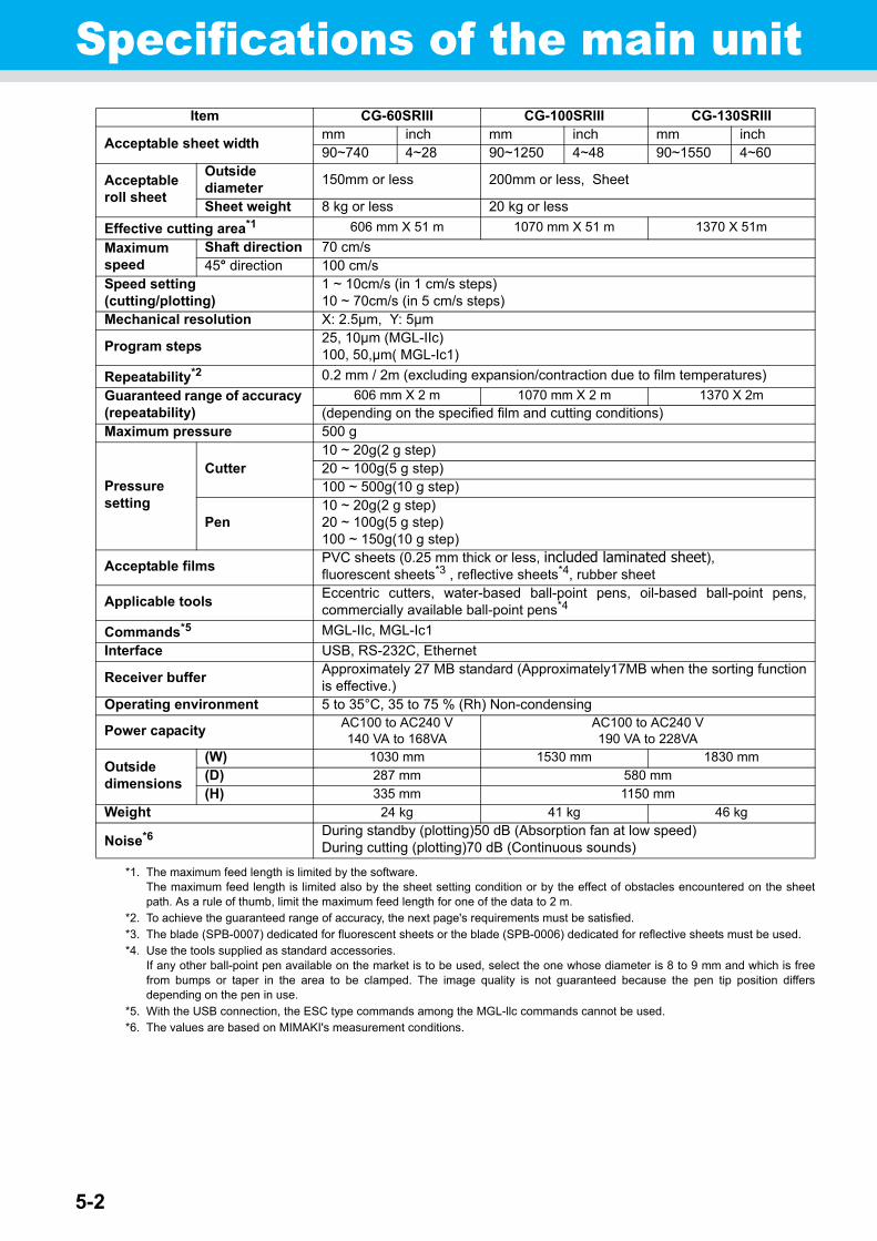
5-2
Specifications of the main unitItem CG-60SRIII CG-100SRIII CG-130SRIII
Acceptable sheet widthmm inch mm inch mm inch90~740 4~28 90~1250 4~48 90~1550 4~60
Acceptable roll sheet
Outside diameter
150mm or less 200mm or less, Sheet
Sheet weight 8 kg or less 20 kg or less
Effective cutting area*1
*1. The maximum feed length is limited by the software.The maximum feed length is limited also by the sheet setting condition or by the effect of obstacles encountered on the sheetpath. As a rule of thumb, limit the maximum feed length for one of the data to 2 m.
606 mm X 51 m 1070 mm X 51 m 1370 X 51m
Maximum speed
Shaft direction 70 cm/s45° direction 100 cm/s
Speed setting(cutting/plotting)
1 ~ 10cm/s (in 1 cm/s steps)10 ~ 70cm/s (in 5 cm/s steps)
Mechanical resolution X: 2.5μm, Y: 5μm
Program steps25, 10μm (MGL-IIc)100, 50,μm( MGL-Ic1)
Repeatability*2
*2. To achieve the guaranteed range of accuracy, the next page's requirements must be satisfied.
0.2 mm / 2m (excluding expansion/contraction due to film temperatures)
Guaranteed range of accuracy (repeatability)
606 mm X 2 m 1070 mm X 2 m 1370 X 2m(depending on the specified film and cutting conditions)
Maximum pressure 500 g
Pressure setting
Cutter10 ~ 20g(2 g step)20 ~ 100g(5 g step) 100 ~ 500g(10 g step)
Pen10 ~ 20g(2 g step)20 ~ 100g(5 g step)100 ~ 150g(10 g step)
Acceptable filmsPVC sheets (0.25 mm thick or less, included laminated sheet), fluorescent sheets*3 , reflective sheets*4, rubber sheet
*3. The blade (SPB-0007) dedicated for fluorescent sheets or the blade (SPB-0006) dedicated for reflective sheets must be used.
Applicable toolsEccentric cutters, water-based ball-point pens, oil-based ball-point pens,commercially available ball-point pens*4
*4. Use the tools supplied as standard accessories.If any other ball-point pen available on the market is to be used, select the one whose diameter is 8 to 9 mm and which is freefrom bumps or taper in the area to be clamped. The image quality is not guaranteed because the pen tip position differsdepending on the pen in use.
Commands*5
*5. With the USB connection, the ESC type commands among the MGL-llc commands cannot be used.
MGL-IIc, MGL-Ic1
Interface USB, RS-232C, Ethernet
Receiver bufferApproximately 27 MB standard (Approximately17MB when the sorting functionis effective.)
Operating environment 5 to 35°C, 35 to 75 % (Rh) Non-condensing
Power capacityAC100 to AC240 V140 VA to 168VA
AC100 to AC240 V190 VA to 228VA
Outside dimensions
(W) 1030 mm 1530 mm 1830 mm(D) 287 mm 580 mm
(H) 335 mm 1150 mm
Weight 24 kg 41 kg 46 kg
Noise*6
*6. The values are based on MIMAKI's measurement conditions.
During standby (plotting)50 dB (Absorption fan at low speed)During cutting (plotting)70 dB (Continuous sounds)
Specifications of the main unit
5-3
1
1
1
1
5
Ap
pen
dix
Repeatability condition
Plotter conditions
• When using a exclusive roll-placing table.• The clamp pressure must be set to “HIGH” .
Sheet setting conditions
• Side margin of the sheet: 20 mm or more• Front side condition of the sheet: No warp or rising• No separation of the sheet from the base paper (no air bubbles between them), which can be caused by
bending of the sheet• The sheet must be loaded properly using the sheet feed function.• The roll sheet must be free from loose rolling . (The right and left end faces must be flat.)
Cutting speed
• 40 cm/s or less (when the cutter supplied with the plotter is used)
Cutting data
• Test pattern for maintenance (continuous 5 strokes in the lengthwise direction)• During cutting, there must be no separation of the sheet from the base paper (no air bubbles between them),
which can be caused by excessive bending of the sheet.
• The specified repeatability may not be guaranteed depending on the material of the sheet to be cut or ink jet media,
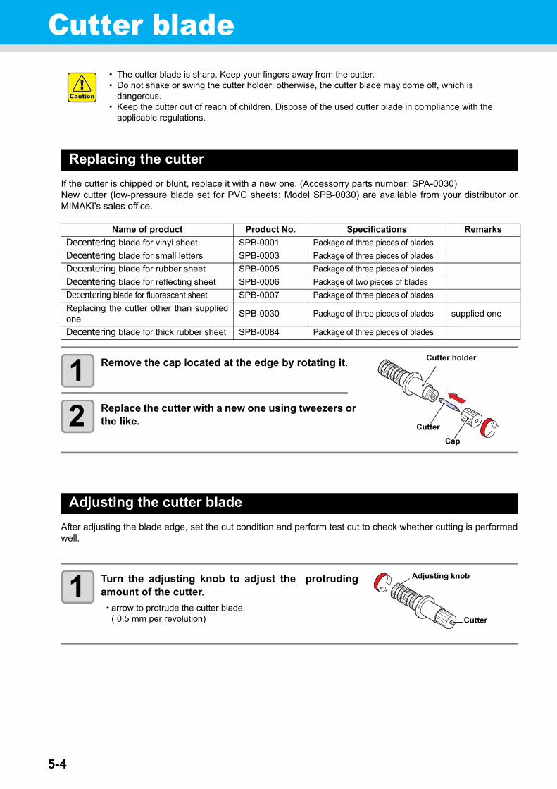
5-4
Cutter blade
Replacing the cutter
If the cutter is chipped or blunt, replace it with a new one. (Accessorry parts number: SPA-0030)New cutter (low-pressure blade set for PVC sheets: Model SPB-0030) are available from your distributor orMIMAKI's sales office.
1 Remove the cap located at the edge by rotating it.
2 Replace the cutter with a new one using tweezers or the like.
Adjusting the cutter blade
After adjusting the blade edge, set the cut condition and perform test cut to check whether cutting is performedwell.
1 Turn the adjusting knob to adjust the protrudingamount of the cutter.
• arrow to protrude the cutter blade. ( 0.5 mm per revolution)
• The cutter blade is sharp. Keep your fingers away from the cutter.• Do not shake or swing the cutter holder; otherwise, the cutter blade may come off, which is
dangerous.• Keep the cutter out of reach of children. Dispose of the used cutter blade in compliance with the
applicable regulations.
Name of product Product No. Specifications Remarks
Decentering blade for vinyl sheet SPB-0001 Package of three pieces of blades
Decentering blade for small letters SPB-0003 Package of three pieces of blades
Decentering blade for rubber sheet SPB-0005 Package of three pieces of blades
Decentering blade for reflecting sheet SPB-0006 Package of two pieces of blades
Decentering blade for fluorescent sheet SPB-0007 Package of three pieces of blades
Replacing the cutter other than suppliedone
SPB-0030 Package of three pieces of blades supplied one
Decentering blade for thick rubber sheet SPB-0084 Package of three pieces of blades
Cutter holder
Cutter
Cap
Cutter
Adjusting knob
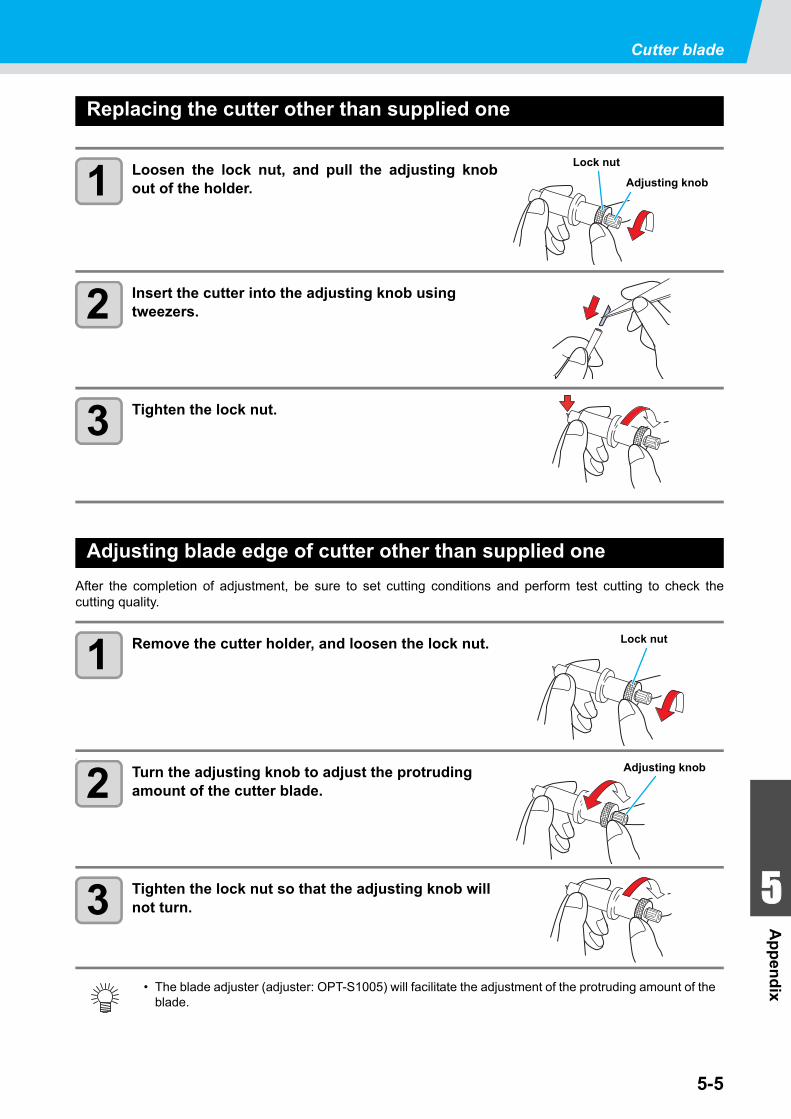
Cutter blade
5-5
1
1
1
1
5
Ap
pen
dix
Replacing the cutter other than supplied one
1 Loosen the lock nut, and pull the adjusting knobout of the holder.
2 Insert the cutter into the adjusting knob using tweezers.
3 Tighten the lock nut.
Adjusting blade edge of cutter other than supplied one
After the completion of adjustment, be sure to set cutting conditions and perform test cutting to check thecutting quality.
1 Remove the cutter holder, and loosen the lock nut.
」
2 Turn the adjusting knob to adjust the protruding amount of the cutter blade.
3 Tighten the lock nut so that the adjusting knob will not turn.
• The blade adjuster (adjuster: OPT-S1005) will facilitate the adjustment of the protruding amount of the blade.
Lock nut
Adjusting knob
Lock nut
Adjusting knob
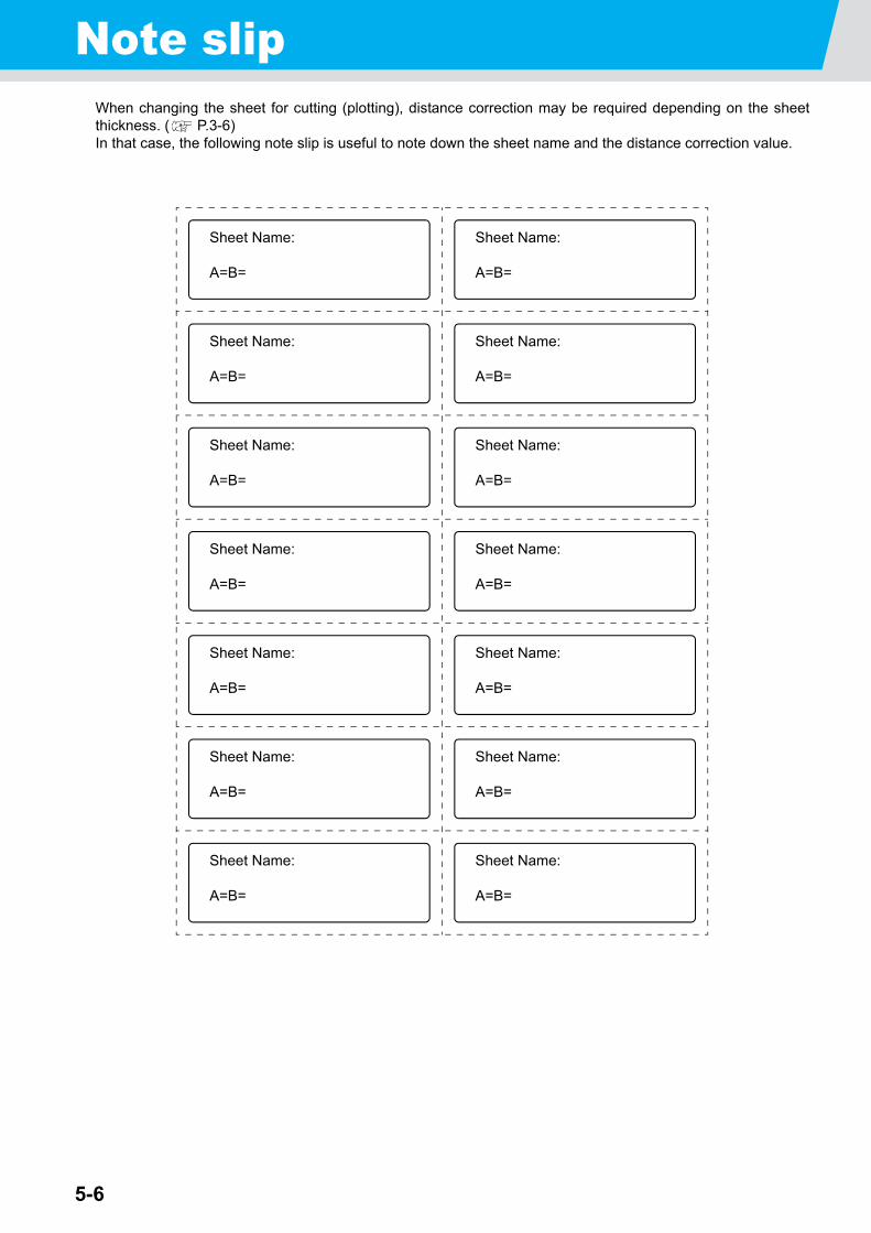
5-6
Note slipWhen changing the sheet for cutting (plotting), distance correction may be required depending on the sheetthickness. ( P.3-6)In that case, the following note slip is useful to note down the sheet name and the distance correction value.
Sheet Name:
A=B=
Sheet Name:
A=B=
Sheet Name:
A=B=
Sheet Name:
A=B=
Sheet Name:
A=B=
Sheet Name:
A=B=
Sheet Name:
A=B=
Sheet Name:
A=B=
Sheet Name:
A=B=
Sheet Name:
A=B=
Sheet Name:
A=B=
Sheet Name:
A=B=
Sheet Name:
A=B=
Sheet Name:
A=B=
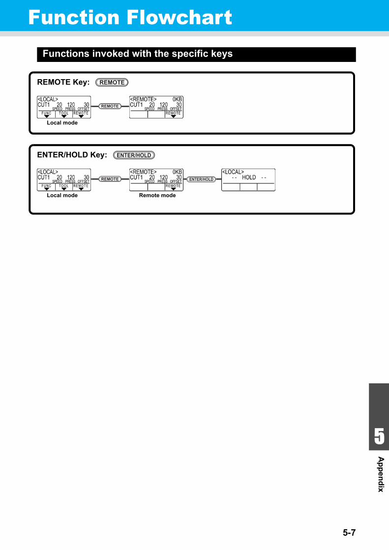
5-7
1
1
1
1
5
Ap
pen
dix
Function FlowchartFunctions invoked with the specific keys
REMOTEREMOTE Key:
Local mode
REMOTE
Local mode
ENTER/HOLDENTER/HOLD Key:
Remote mode
REMOTE ENTER/HOLD
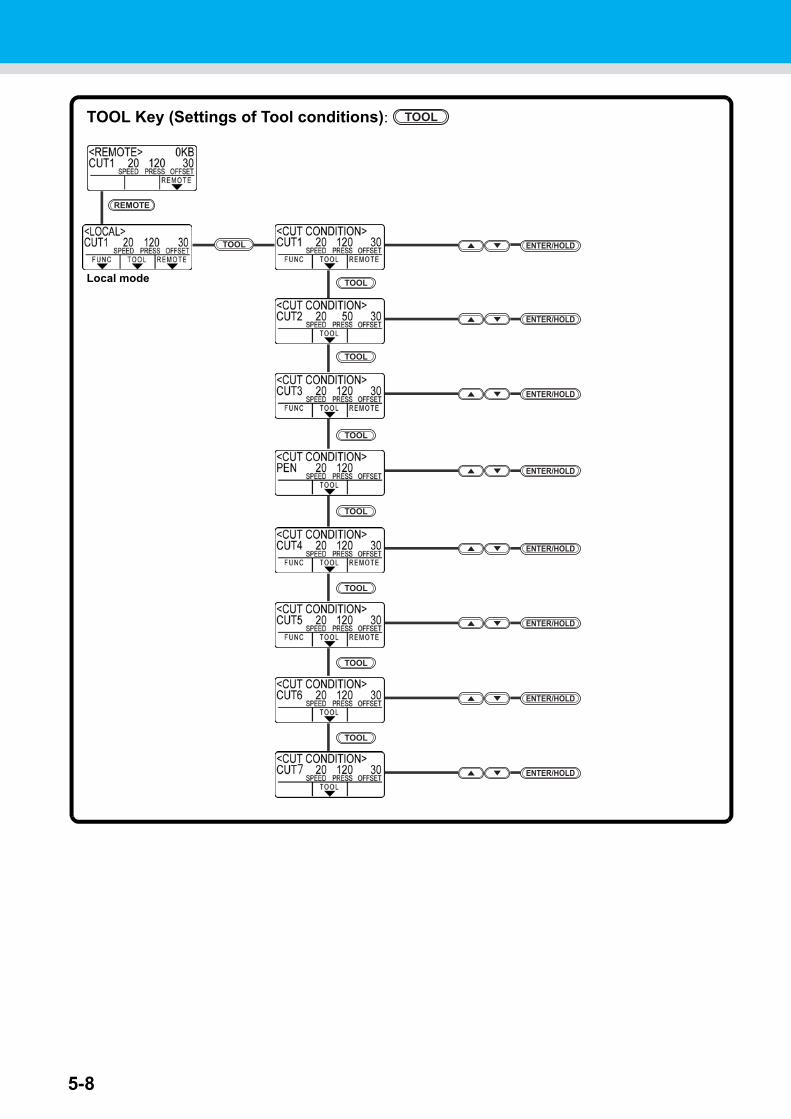
5-8
TOOL
TOOL
REMOTE
TOOL Key (Settings of Tool conditions):
Local mode
ENTER/HOLD
TOOL
ENTER/HOLD
ENTER/HOLD
ENTER/HOLD
ENTER/HOLD
ENTER/HOLD
ENTER/HOLD
ENTER/HOLD
TOOL
TOOL
TOOL
TOOL
TOOL
TOOL
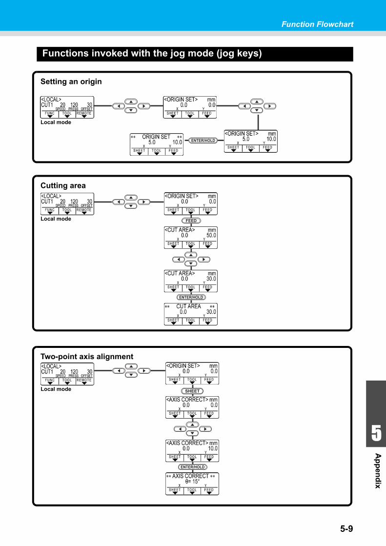
Function Flowchart
5-9
1
1
1
1
5
Ap
pen
dix
Functions invoked with the jog mode (jog keys)
Local mode
Setting an origin
ENTER/HOLD
Local mode
Cutting area
FEED
ENTER/HOLD
Local mode
Two-point axis alignment
SHEET
ENTER/HOLD
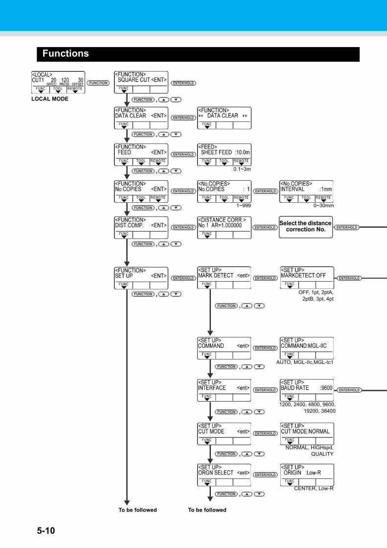
5-10
Functions
,FUNCTION
LOCAL MODE
To be followed
,FUNCTION
,FUNCTION
OFF, 1pt, 2ptA,2ptB, 3pt, 4pt
AUTO, MGL-IIc,MGL-Ic1
1200, 2400, 4800, 9600,19200, 38400
ENTER/HOLDENTER/HOLDENTER/HOLD
ENTER/HOLD
ENTER/HOLD
ENTER/HOLDENTER/HOLD
,FUNCTION
,FUNCTION
,FUNCTION
NORMAL, HIGHspd,QUALITY
ENTER/HOLD
,FUNCTION
ENTER/HOLDFUNCTION
To be followed
Select the distance correction No.
,FUNCTION
ENTER/HOLD
,FUNCTION
ENTER/HOLD
,FUNCTION
ENTER/HOLD
0.1~3m
ENTER/HOLD
1~999 0~30mm
ENTER/HOLD ENTER/HOLD
CENTER, Low-R
ENTER/HOLD
,FUNCTION
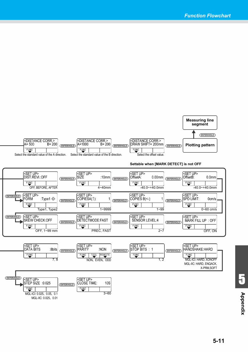
5-11
Function Flowchart
1
1
1
1
5
Ap
pen
dix
MGL-ICI: HARD, XONOFFMGL-IIC: HARD, ENQACK,
X-PRM,SOFT
ENTER/HOLD
1, 2NON、EVEN、ODD
ENTER/HOLD ENTER/HOLD
7, 8
MGL-ICI: 0.025、0.05、0.1MGL-IIC: 0.025、0.01
3~60
ENTER/HOLD
ENTER/HOLD
2~7PREC, FASTOFF, 1~99 mm
ENTER/HOLD ENTER/HOLD
-40.0~+40.0mm
ENTER/HOLD
Type1, Type2
-40.0~+40.0mm4~40mm
1~9999
OFF, BEFORE, AFTER
1~99 0~60 cm/s
ENTER/HOLD ENTER/HOLD
ENTER/HOLD ENTER/HOLD ENTER/HOLD
Settable when [MARK DETECT] is not OFF
ENTER/HOLD
ENTER/HOLD
Measuring line segment
ENTER/HOLD
Select the offset value.Select the standard value of the B direction.Select the standard value of the A direction.
ENTER/HOLD ENTER/HOLD
ENTER/HOLD
Plotting pattern
ENTER/HOLD
0~99,FUNCTION
OFF, ON
ENTER/HOLD
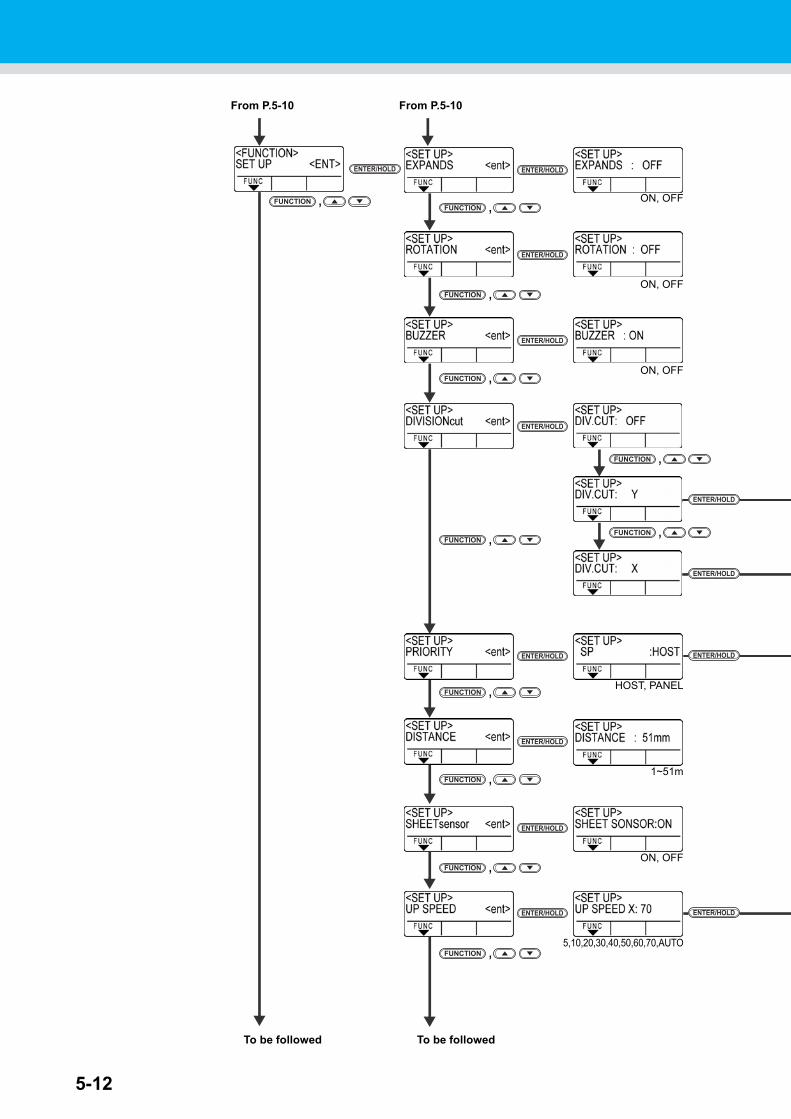
5-12
ENTER/HOLD
ENTER/HOLD
ENTER/HOLD
,FUNCTIONON, OFF
5,10,20,30,40,50,60,70,AUTO
ENTER/HOLD
ENTER/HOLD
,FUNCTION
,FUNCTION
HOST, PANEL
1~51m
,FUNCTION
ENTER/HOLD
ENTER/HOLD
To be followed
,FUNCTION
ENTER/HOLDENTER/HOLD
ENTER/HOLD
ENTER/HOLD
,FUNCTION
,FUNCTION
ON, OFF
ON, OFF
ON, OFF
,FUNCTION
To be followed
From P.5-10 From P.5-10
,FUNCTION
,FUNCTION
ENTER/HOLD
,FUNCTION
ENTER/HOLD
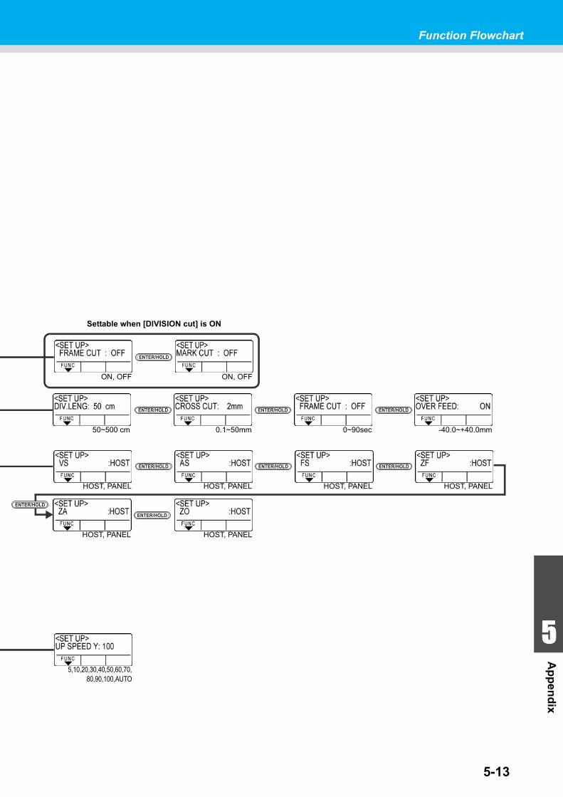
5-13
Function Flowchart
1
1
1
1
5
Ap
pen
dix
ENTER/HOLD
ON, OFFON, OFF
Settable when [DIVISION cut] is ON
5,10,20,30,40,50,60,70,80,90,100,AUTO
HOST, PANEL
ENTER/HOLD
HOST, PANELHOST, PANEL
ENTER/HOLD ENTER/HOLD
HOST, PANEL
HOST, PANEL HOST, PANEL
ENTER/HOLD
ENTER/HOLD
-40.0~+40.0mm
ENTER/HOLD
0~90sec0.1~50mm50~500 cm
ENTER/HOLD ENTER/HOLD
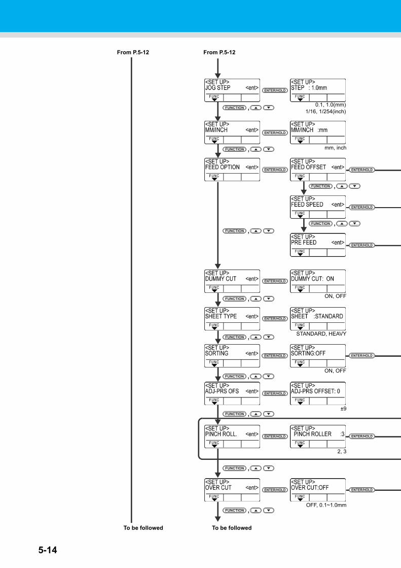
5-14
,FUNCTION
,FUNCTION
ENTER/HOLD ENTER/HOLD
2, 3
ENTER/HOLD
±9,FUNCTION
ENTER/HOLD
,FUNCTION
STANDARD, HEAVY,FUNCTION
ENTER/HOLD
ON, OFF
ENTER/HOLDENTER/HOLD
,FUNCTION
,FUNCTION
ENTER/HOLD
mm, inch
To be followed
From P.5-12From P.5-12
ENTER/HOLD
,FUNCTION 0.1, 1.0(mm)1/16, 1/254(inch)
To be followed
,FUNCTION
ENTER/HOLD
ENTER/HOLD
ENTER/HOLD
OFF, 0.1~1.0mm,FUNCTION
ENTER/HOLD
,FUNCTION
ENTER/HOLD ENTER/HOLD
ON, OFF
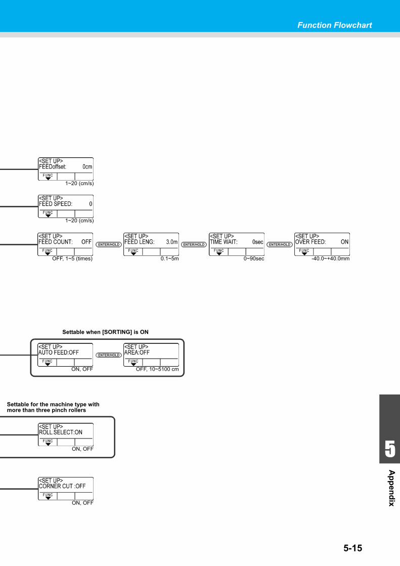
5-15
Function Flowchart
1
1
1
1
5
Ap
pen
dix
ENTER/HOLD
OFF, 10~5100 cmON, OFF
Settable when [SORTING] is ON
Settable for the machine type with more than three pinch rollers
1~20 (cm/s)
ON, OFF
-40.0~+40.0mm
ENTER/HOLD
0~90sec0.1~5mOFF, 1~5 (times)
ENTER/HOLD ENTER/HOLD
1~20 (cm/s)
ON, OFF
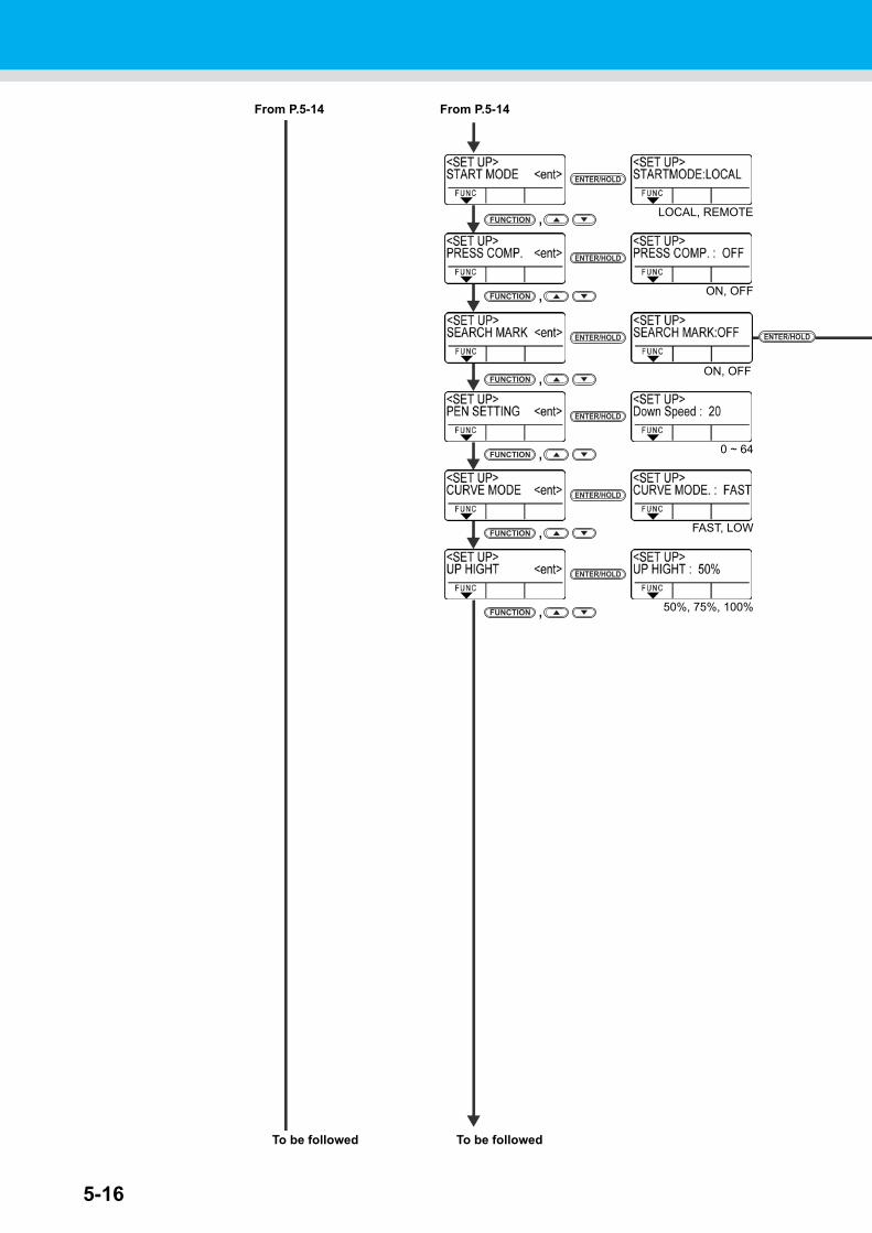
5-16
From P.5-14
To be followed
From P.5-14
To be followed
ENTER/HOLD
LOCAL, REMOTE,FUNCTION
ENTER/HOLD
ON, OFF,FUNCTION
ENTER/HOLD
ENTER/HOLD
0 ~ 64,FUNCTION
ENTER/HOLD
50%, 75%, 100%,FUNCTION
ENTER/HOLD
ON, OFF,FUNCTION
ENTER/HOLD
FAST, LOW,FUNCTION
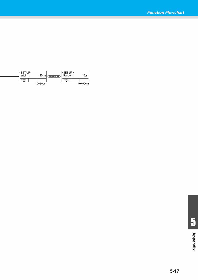
5-17
Function Flowchart
1
1
1
1
5
Ap
pen
dix
ENTER/HOLD
10~30cm 10~50cm
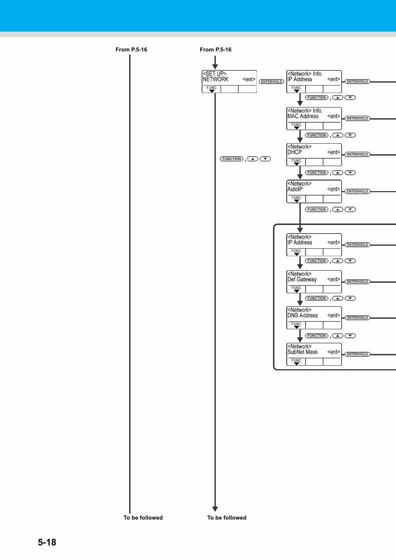
5-18
ENTER/HOLD
,FUNCTION
ENTER/HOLD
From P.5-16
ENTER/HOLD
,FUNCTION
ENTER/HOLD
,FUNCTION
ENTER/HOLD
,FUNCTION
To be followed
From P.5-16
ENTER/HOLD
ENTER/HOLD
,FUNCTION
ENTER/HOLD
,FUNCTION
ENTER/HOLD
,FUNCTION
,FUNCTION
To be followed
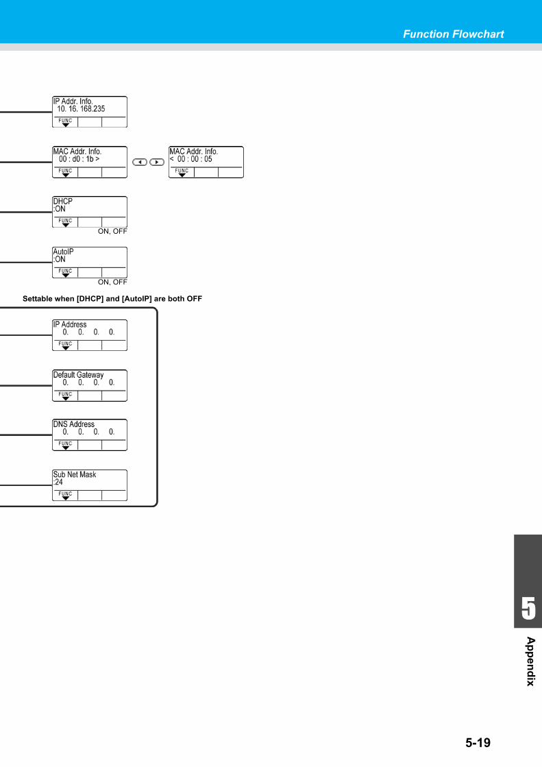
5-19
Function Flowchart
1
1
1
1
5
Ap
pen
dix
ON, OFF
ON, OFF
Settable when [DHCP] and [AutoIP] are both OFF
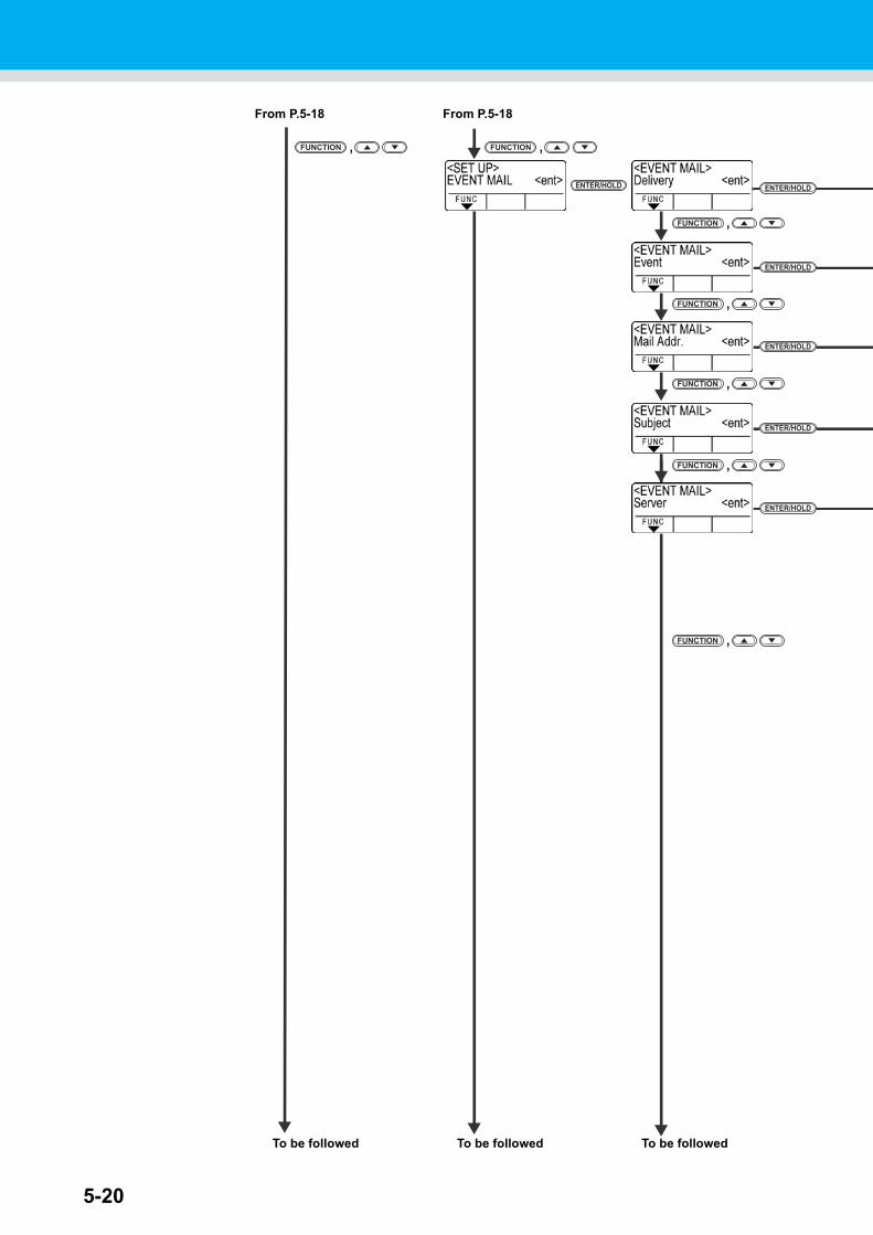
5-20
From P.5-18From P.5-18
ENTER/HOLD
ENTER/HOLD
ENTER/HOLD
ENTER/HOLD
,FUNCTION
,FUNCTION
,FUNCTION
,FUNCTION
To be followed To be followed
,FUNCTION
,FUNCTION
To be followed
ENTER/HOLD ENTER/HOLD
,FUNCTION
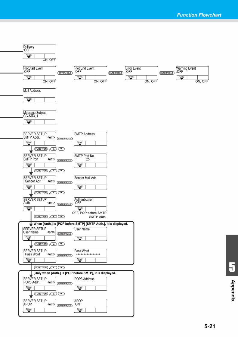
5-21
Function Flowchart
1
1
1
1
5
Ap
pen
dix
ON, OFF
ENTER/HOLD
ON, OFFON, OFF
ENTER/HOLD ENTER/HOLD
ON, OFF
ENTER/HOLDENTER/HOLD
,FUNCTION
ENTER/HOLD
,FUNCTION
OFF, POP before SMTPSMTP Auth.
ENTER/HOLD
,FUNCTION
ENTER/HOLD
,FUNCTION
ENTER/HOLD
,FUNCTION
ENTER/HOLD
,FUNCTION
ENTER/HOLD
When [Auth.] is [POP before SMTP] [SMTP Auth.], it is displayed.
[Only when [Auth.] is [POP before SMTP], it is displayed.
ENTER/HOLD
,FUNCTION
ON, OFF
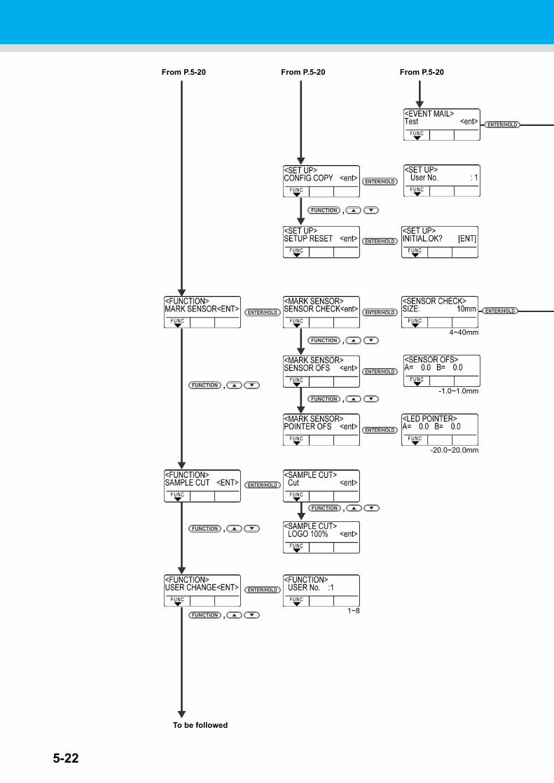
5-22
From P.5-20From P.5-20From P.5-20
ENTER/HOLD
,FUNCTION
ENTER/HOLD
ENTER/HOLD ENTER/HOLDENTER/HOLD
,FUNCTION
,FUNCTION
4~40mm
-1.0~1.0mm
-20.0~20.0mm
ENTER/HOLD
ENTER/HOLD
,FUNCTION
To be followed
ENTER/HOLD
,FUNCTION
,FUNCTION
ENTER/HOLD
,FUNCTION
ENTER/HOLD
1~8
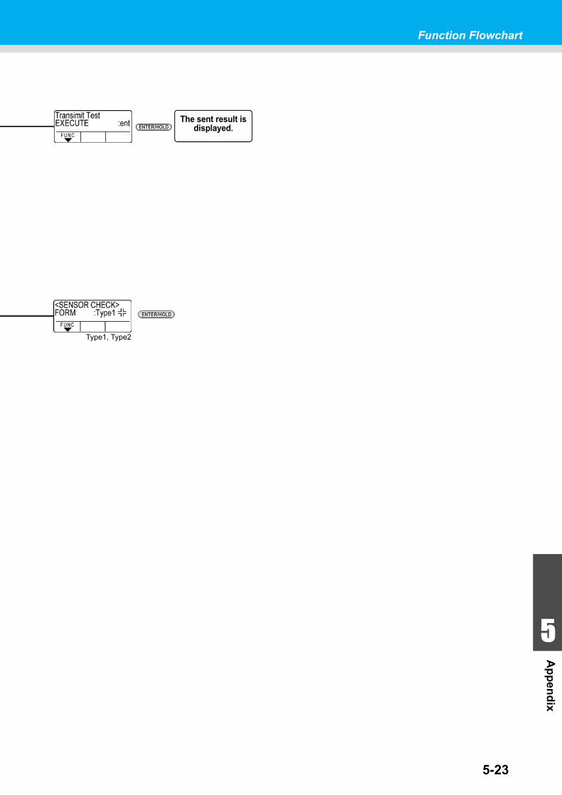
5-23
Function Flowchart
1
1
1
1
5
Ap
pen
dix
ENTER/HOLD
ENTER/HOLD
,FUNCTION
ENTER/HOLD
,FUNCTION
Type1, Type2
ENTER/HOLDThe sent result is
displayed.
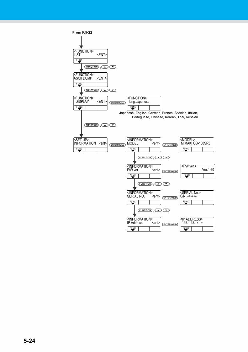
5-24
ENTER/HOLD
,FUNCTION
From P.5-22
ENTER/HOLD
,FUNCTION
ENTER/HOLD
ENTER/HOLD ENTER/HOLD
,FUNCTION
,FUNCTION
,FUNCTION
ENTER/HOLD
Japanese, English, German, French, Spanish, Italian,Portuguese, Chinese, Korean, Thai, Russian
,FUNCTION

Function Flowchart
5-25
1
1
1
1
5
Ap
pen
dix
ENTER/HOLD
,FUNCTION
ENTER/HOLD
,FUNCTION

5-26

D202472-16-19052014

IT
FW : 2.6© MIMAKI ENGINEERING CO., LTD.2014