Embed Size (px)
DESCRIPTION
grahics lab
Citation preview
1
LIST OF EXPERIMENTS
01 AN INTRODUCTION OF CAD SOFTWARE AND ITS UTILITIES IN THE ENGINEERING SOFTWARE.
02 STUDY OF THE BASIC INITIAL SETTING AND VIEWING OF DRAFT-ING SOFTWARE INTERFACE.
03 STUDY OF VARIOUS TOOL BAR OPTIONS AND EXERCISES TO FAMILIARIZE ALL THE DRAWING TOOLS.
04 STUDY AND IMPLEMENTATION OF CO-ORDINATE SYSTEMS AND UCS.
05 USE OF BASIC ENTITIES IN 2D.
06 USE OF VARIOUS MODIFY COMMANDS OF DRAFTING SOFTWARE.
07 DIMENSIONING IN 2D AND 3D ENTITIES.
08 DRAW DIFFERENT TYPES OF 3D MODELLING ENTITIES USING VIEWING COMMANDS, TO VIEW THEM (ISOMETRIC PROJEC-TION).
09 SECTIONING OF SOLID PRIMITIVES AND RENDERING IN 3D.
10 INTERSECTION OF SOLID PRIMITIVES.

2
EXPERIMENT -1
AIM: - AN INTRODUCTION OF CAD SOFTWARE AND ITS UTILITIES IN ENGI-NEERING FIELDS.
OBJECTIVE: - An awareness about CAD software and its applications.
THEORY: - Drawings are easier to interpret if you set standards to enforce consistency. You
can set standards for layer names, dimension styles, and other elements; check drawings against
these standards; and then change any properties that do not conform.
1. COMPUTER GRAPHICS: -It refers to the generation of graphical outputs using computer.
Computer graphics techniques are being applied to the making of cartoons. Drawing a series of
action sequences which when run at high speed, creates the illusion of moving pictures, appear
to move. This is known as animation.
CADD- Computer Aided Design and Drafting.
CAD- Computer Aided Design .
CAM- Computer Aided Manufacturing. CAM uses results of CAD.
CAD is not a substitute for design/ drawing concept. It’s only a tool that can be used to
supplement traditional methods. It’s parallel to use of calculators. They are used for solving ma-
thematics problem but still knowledge of mathematics is required by user to solve it. What is
eliminated is the tedious task of performing long hand mathematical manipulations.
Applications of CAD: - An engineer designing a new car body can see the design on the screen.
Whenever he needs to make changes he can do it easily and the change can also be stored. He
can reduce or enlarge any part of design, change of colors and check pluma. Overall, the design
cycle time is reduced drastically. The new car comes on the road in a remarkably shot span of
time.
3
2. Application in various fields: -
a) Mechanical: - design of machine elements, CNC machine tools.
b) Automotive: - kinematics, Hydraulics & Steering systems.
c) Electrical: - circuit layout, panel design & control system.
d) Electronics: - schematic diameter of PC’s, IC’s etc.
e) Communication: - communication network, satellite transmitting pictures,
T.V. telecasting etc.
f) Civil: - Mapping, contour Plotting, Building drawing & Structural design.
g) Architectural: - Town planning, Interior decorations, Modeling, and multistory
complexes.
h) Aerospace: - Design of spacecraft, Flight simulator etc.
3. Advantages of CAD
a) Combination of human brain and machine speed produces better results in less
time.
b) More accurate, it leads to better quality drawing.
c) Drawing can be stored in database.
d) Faster and easy correction/ modifications of a design is possible and drawing
errors can be visualize on screen.
e) Visual modeling of any object / engineering component is possible.
f) CAD is used for creation, modification, analysis and optimization of designs for
Improved engineering Productivity.
g) One can create a library and use a single drawing, a no’s of times whenever re-
quired.
h) Color graphics help to display more distinct information on screen.
4. SOFTWARES: -Auto-CAD-2004, Auto-CAD 2007 (Mechanical), AutoCAD 2007
(Electrical), Auto-Desk, Inventor PRO –11,Pro-E, STADD, CATIA,I-DEAS etc.
4
EXPERIMENT -2 AIM: - STUDY OF THE BASIC INITIAL SETTING AND VIEWING OF THE DRAFT-
ING SOFTWARE INTERFACES.
OBJECTIVE: - To learn initial setting and viewing of the drafting software interfaces.
THEORY: To find out Auto-CAD package and set its required setting for drawing in the auto-
CAD window.
How to Start your PC.
Opening Auto-CAD Window.
Description of Auto-CAD window.
Setting GUI (Graphic User Interface) for drawing.
How to Start your PC.
Switch “ON” main switch. Switch “ON” UPS. Switch “ON” CPU and Monitor.
Opening Auto CAD Window.
First go to Start, then go to programme file and then go to Auto-CAD/Auto Desk. Select respective auto-CAD window, click ok.
Open an existing drawing:
To opens an existing drawing select from a list from the fore most recently open draw-
ing. Also display brows button that you choose look for another file.
Start a drawing from scratch
Open a new drawing based on the measurement system you choose-English (inches) or
Metric (millimeters) system.
Use a Template:
Open a new drawing based on a template you select from a list. The list display on a tem-
plate files that exits in the drawing file locations specified in the option dialog box Template
files stores all the setting for a drawing.
5
Setting Drawing Units: Drawing units are sets as per drawing units given in the drawing to be
done. It may be in MKS or SI system such as millimeters or in inches in case of distance
units and similarly for angular measurements it may be Degree, Radian or Grade e.t.c.
To set drafting Units: In the Drawing units dialog box set the units value for drawing.
Type “units” at command window. Press ent. Select units in mm or inches. Select Precision,
0.00 or 0.000 or 0 itself. Ent. Select angular direction, clockwise, leave box blank,for anti
clockwise, select/ click ok.
Command: Units
Setting the Limits of Drawing:
Limits of Drawing specify the area in which the drawing is to be drawn.
Command: Limits. Enter.
Specify the lower left corner of the area: say (00,00)
Specify the upper right corner of the area: (297, 420) o(420, 297 ) for land scape size. Press ent. Write “zoom” . Ent. Type “All” ent.
After specifying the limits we set Gid.
Setting of Grid SpacingType grid, press ent. Clk on grid dialog box . set grid spacing 5/ 10 / 15 as desired. Press ent.
Setting of Snap Spacing. Click on snap . ent value as 5/10/ 15 as desired. Ent.
This will zoom all the limits of drawing. After this we can draw the required drawing
DRAFTING SOFTWARE INTERFACES
Menus, Toolbars and Tool Palettes..
You can use several menus, shortcut menus, palettes, and toolbars for access to fre-
quently used commands, settings, and modes.
The Command Window.
You can display commands, system variables, options, messages, and prompts in a lock-
able and resizable window called the command window.

6
Design Center.
With Design Center, you can manage block references and other content such as layer,
definitions, layouts, and text styles etc.
Customize the Drawing Environment.
Many elements of the working environment can be customized to fit your needs.
Pointing Devices:
You can use as your pointing device a mouse, a digitizing puck, and it may have
more than two buttons. You can use several menus, shortcut menus, tool palettes, and toolbars
for access to frequently used commands, settings, and modes.
Tool Palettes
Tool palettes are tabbed areas within the Tool Palettes window that provide an ef-
ficient method for organizing, sharing, and placing blocks and hatches. Tool palettes can al-
so contain custom tools provided by third-party developers.
Insert Blocks and Hatches Using Tool Palettes
Tool palettes are tabbed areas within the Tool Palettes window. Drag blocks and hatches
from a tool palette to place these objects quickly on a drawing.
Change Tool Palette Settings
The options and settings for tool palettes are accessible from shortcut menus in different
areas on the Tool Palettes window.
Control Tool Properties You can change the insertion properties or pattern/
Properties of any tool on a tool palette.
Customize Tool Palettes You can add tools to a tool palette by veral methods.
Save and Share Tool Palettes: Save and share a tool palette by exporting it or importing it
as a tool palette file.
Toolbars:
Use buttons on toolbars to start commands, display fly out toolbars, and display
tool tips. Toolbars contain buttons that start commands. When you move the pointing device
over a toolbar button, the tool tip displays the name of the button. Buttons with a small black
7
triangle in the lower-right corner have fly outs that contain related commands. With the
cursor over the icon, hold down the pick button until the fly out appears. The Standard tool-
bar at the top of the drawing area is displayed by default. This toolbars are Draw tools, Mod-
ify tools etc.
Shortcut Menus:
Display a shortcut menu for quick access to commands that are relevant to
your current activity.
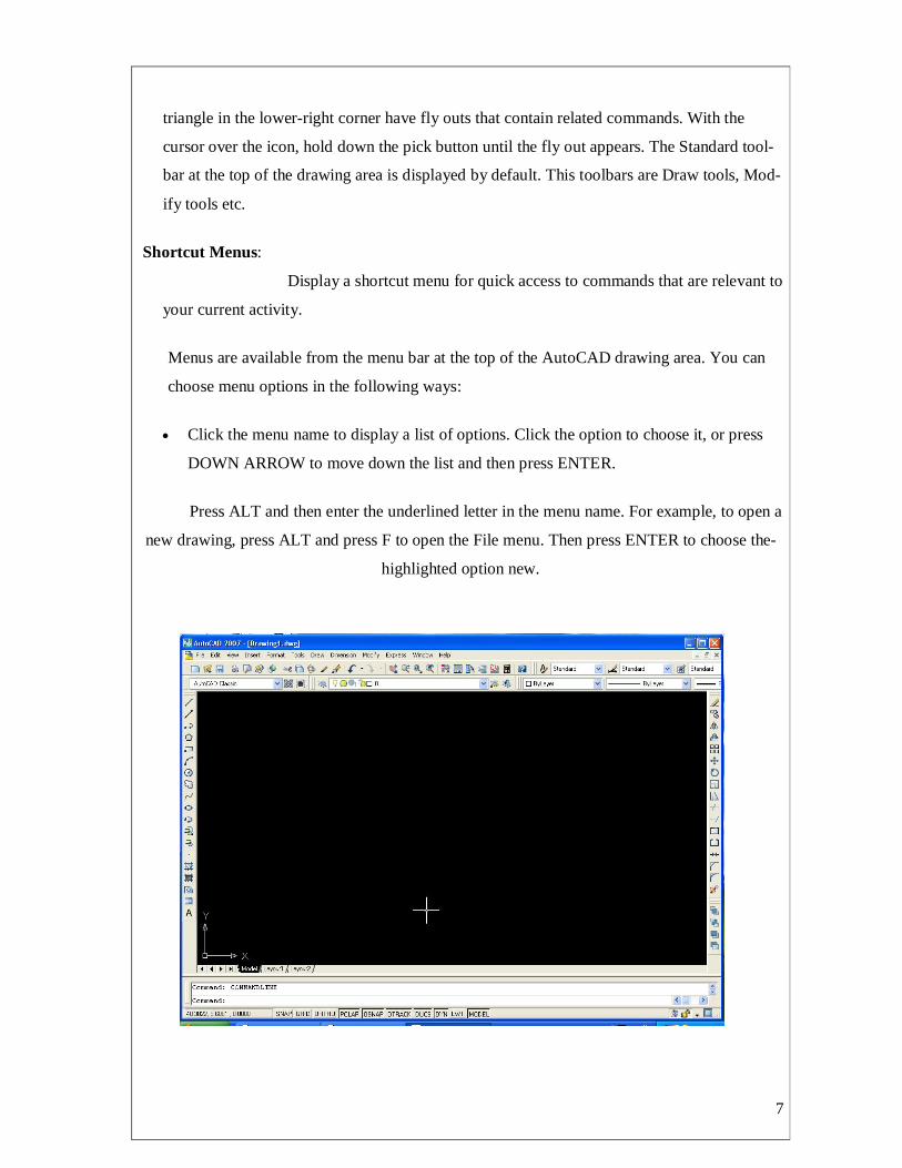
Menus are available from the menu bar at the top of the AutoCAD drawing area. You can
choose menu options in the following ways:
Click the menu name to display a list of options. Click the option to choose it, or press
DOWN ARROW to move down the list and then press ENTER.
Press ALT and then enter the underlined letter in the menu name. For example, to open a
new drawing, press ALT and press F to open the File menu. Then press ENTER to choose the-
highlighted option new.
8
EXPERIMENT-3
AIM: - STUDY OF VARIOUS TOOLBAR OPTIONS AND EXERCISES TO FAMI-LIARIZE DRAWING TOOLS.
OBJECTIVE: - To learn different drawing tools commonly used in Auto-CAD.
THEORY: - There are different toolbar options in Auto-CAD. These are the main toolbars:
Standard Toolbar: There are following tools in this option:
New: To create a new drawing.
Open: To open already existing drawing. Click on open icon at menu bar, select desired file and
click open.
Save: To save already existing drawing. By save as or by pressing Ctrl+S and give the name of
file.
Plot: To plot a drawing, select an existing drawing by pressing Ctrl+A, then go to File in
menu bar, select plot and then select type of plotter, give no’s of copies and click OK.
Un-do and Re-do: It is used for editing and do and undo the drawing by clicking on undo icon
for undoing the latest drawing and click on re-do icon for re-doing the latest drawing.
Cut: It is used to cut or delete the selected part of drawing. Select the drawing to be cut by
Pressing Ctrl+A and press cut icon on menu bar (Scissor).
Match Property: It is used to adjust same dimensions and color of a drawing or a part of
drawing with existing one. Go to the match property icon and click on it, select the
original drawing with whom you like to match and then, click on the drawing to which
you like to match.
Pan: It is used to move all the drawing on the screen at a time. Click on Pan icon on menu bar
and go to screen and move the mouse by pressing left button. All the drawings will move
together.
Zoom: It is used to magnify the existing drawing. Click on the Zoom icon on menu bar or by
Scrolling the scroll bar of mouse up or down.
Draw Tools: There are different draw tools to draw different types of drawing i.e. Point, line,
curve line, circle, polygon, rectangle, ellipse, arc etc. Each of these will be discuss later on.
Modify Tools: These tools are used for modifying the existing drawing. These are erase, copy,
mirror, array, explode, break, trim, extend, fillet & chamfer. Each of these will be discuss later
on.

9
Drawing aids: These are the helping tools used to assist drafter to draw complicated draw-
ing but not a draw tools. These are very helpful to make a drawing easy. These are SNAP,
GRID, ORTHO, OSNAP, OTRACK etc.
Snap: It is useful for specifying precise points with the arrow keys or the pointing device.
Grid: It is a rectangular pattern of dots that extends over the area you specify as the drawing
limits. Using the grid is similar to placing a sheet of grid paper under a drawing.
Ortho: - This aids to draw horizontal and vertical lines when it is on.
Polar: - It is used to draw lines at an angle to the reference line either clockwise or anticlock-
wise depending upon the requirement of drafter.
OSNAP (Object Snap) and OTRACK (Object Snap tracking): - This is used to make proper
connection / attachment of lines with the other diagram or lines when it reach to the nearest
point. It facilitates to identify the required co-ordinate points such as mid point, center, end
point, tangents etc which are otherwise very difficult to track and make proper connection of
lines or to complete a drawing. It has following features. End point, Mid point, Center, Node,
Quadrant, Intersection, Extension, Perpendicular, Tangent, Nearest point, apparent intersection
and parallel.
LWT: - Used to give required thickness of lines as defined in Engineering drawing. e.g. Border
line, Title block line , Center line etc.
Model: -This is used to set the drawing sheet as required by the designer to follow standard pro-
cedure of drawing.
Toolbars:
These are Draw tools, Modify tools, Layers Blocks, Properties, Dimensioning tools etc.
Draw Tools: These are Lines, Arcs, Circles, Poly-lines, Polygon Rectangle, Ellipse, Text Ellip-
tical Arc, Hatch, Blocks and Region. Details of each of them will be discuss in Exercise no. 05.
Modify tools: These tools are used to modify existing drawing. Commonly used commands are
Trim, Cut, Extend, Copy, Move, Erase, Mirror, Offset, Rotate, Chamfer, Fillet and Array. De-
tails of these are explain in exercise No. 06
Layers: These are organizing tools, which are used to print drawing as per required dimension.
Such as if we do not required certain types of lines like hidden line, we can take a copy of the
existing drawing in required model. These are; State, Name, On/Off, Freeze, Lock, Color, Line
type, Line weight, Plot Style and Plot.

10
On/Off: This is used to put the Layers active or inactive. Click on ‘On’ icon, it will be active,
and click on again it will be inactive.
Name : It give name of the defined layer.
State: It used to set the selected layers as current layers.
Freeze: It is used to freeze selected layers of drawing to make it invisible so that it can speed up
rendering processes / Zoom/ Rotate speedily. When Thawed layers are put on it will be active
for all type of operations.
Lock/Unlock: Used to lock the drawing when it is ‘ON’ . Unlock it for movement.
Colour: To give different Type of colour to different lines, as required. Such as green for center-
line, Blue for dimensioning lines etc.
Line Type: Diffferent types of lines (e.g .thicknes) with different profile can be made in this
tools.
Plot Style: Changes the plot style associated with the selected layers.
Plot: Control whenever the selected layers are plotted.
11
EXPERIMENT – 4
AIM :- STUDY AND IMPLEMENTING OF CO-ORDINATE SYSTEMS AND UCS.
OBJECTIVE :- An awareness about the different coordinate system THEORY:-
There are four different types of coordinate systems used in AutoCAD to locate the point
on screen. In AutoCAD considering the screen as XY plane does 2D drafting. X-value is consid-
er horizontally and Y- value are taken vertically. By default ,the lower left corner is consider as
origin(0,0) AUTOCAD uses the following coordinate systems:
(a) Absolute coordinate system
(b) Relative coordinate system
(C) Polar coordinate system
(d) Direct Distant Entry System
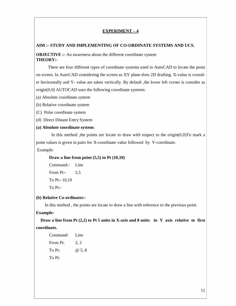
(a) Absolute coordinate system:
In this method ,the points are locate to draw with respect to the origin(0,0)To mark a
point values is given in pairs for X-coordinate value followed by Y-coordinate.
Example:
Draw a line from point (5,5) to Pt (10,10)
Command:- Line
From Pt:- 5,5
To Pt:- 10,10
To Pt:- (b) Relative Co-ordinates:-
In this method , the points are locate to draw a line with reference to the previous point.
Example:
Draw a line from Pt (2,2) to Pt 5 units in X-axis and 8 units in Y axis relative to first
coordinate.
Command: Line
From Pt: 2, 2
To Pt: @ 5, 8
To Pt:
12
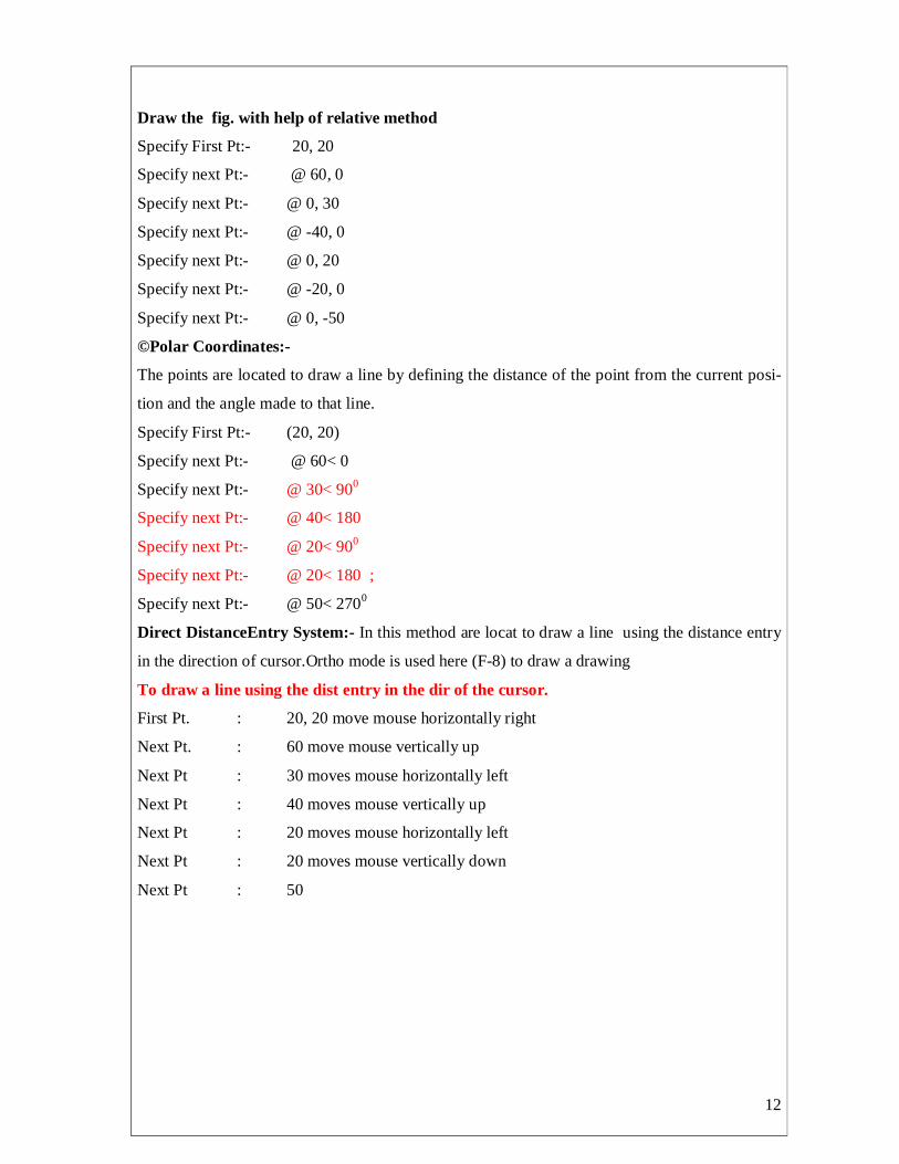
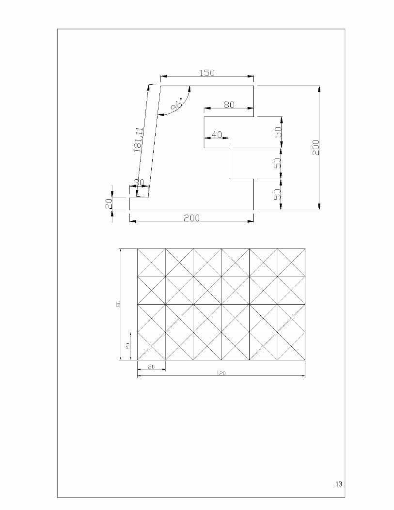
Draw the fig. with help of relative method
Specify First Pt:- 20, 20
Specify next Pt:- @ 60, 0
Specify next Pt:- @ 0, 30
Specify next Pt:- @ -40, 0
Specify next Pt:- @ 0, 20
Specify next Pt:- @ -20, 0
Specify next Pt:- @ 0, -50
©Polar Coordinates:-
The points are located to draw a line by defining the distance of the point from the current posi-
tion and the angle made to that line.
Specify First Pt:- (20, 20)
Specify next Pt:- @ 60< 0
Specify next Pt:- @ 30< 900
Specify next Pt:- @ 40< 180
Specify next Pt:- @ 20< 900
Specify next Pt:- @ 20< 180 ;
Specify next Pt:- @ 50< 2700 Direct DistanceEntry System:- In this method are locat to draw a line using the distance entry
in the direction of cursor.Ortho mode is used here (F-8) to draw a drawing
To draw a line using the dist entry in the dir of the cursor.
First Pt. : 20, 20 move mouse horizontally right
Next Pt. : 60 move mouse vertically up
Next Pt : 30 moves mouse horizontally left
Next Pt : 40 moves mouse vertically up
Next Pt : 20 moves mouse horizontally left
Next Pt : 20 moves mouse vertically down
Next Pt : 50
13

14
EXPERIMENT- 5
AIM: - USE OF BASIC ENTITI.ES IN 2D
OBJECTIVE: - To learn the basics of 2D entities.
THEORY: - In the 2D entities, we can draw different drawings by use of different draw com-
mands.i.e.line arc, circle, rectangle, polygon, ellipse etc. In this exercise we will draw different
types of drawing by using these commands with the help of different methods.
PROCEDURE:
The some exercises are drawn with the help of the following commands:
P- Line Command or PL Command: -
A polyline is a connected sequence of line and arc segments. It has feature to change the line
width.
Command: P line or PL
Specify the start Pt: select the starting Pt by using mouse.
Select different Pts and press enter. Current line width is 0.000 or change if required. You can
change the line to an arc and then to a line of same or different thickness. (See Fig 01)
Command: – Rectangle
A rectangle is a polyline based on two opposite Corner Pts called diagonal points.
(See Fig 2)
Draw a rectangle defined by diagonal Pt (10, 10) and (30, 20)
Command: - Recta. Ent.
First corner: P1 ( 10, 10). Ent.
Second corner: P2 (30, 20). Ent. (See Fig 03) Rectangles can be drawn by lines commands also. Line, Ent Pt.
P1(10,10) Ent P2 ( 40,10) Ent P3 ( 40, 40). Ent P4 (10, 40 ). Ent. C . Ent. (See Fig 04 )
POLYGON:- It enables us to draw a polygon consists of more than four sides of regular size.
(a) Polygon Command: - Edge method
The polygon command is used to draw a regular polygon for a given length of the edge or
side.
Command: Polygon
Enter no. Of sides<4>: 6
15
Specify <center of polygon> or edge: E
Specify first end Pt of edge: select using mouse
Specify second end PT of edge: @30< 0
(b) Draw a polygon of 8 sides with center (50, 50) inscribed in a circle of radius 40
units.
Command: Polygon
No. Of sides: 8
Edge / < center of Polygon>: 50, 50
Inscribed in a circle / circumscribed about circle (I /C) : I
Radius of Circle –40
(c) Draw a octagon with center (140, 50) circumscribed on a circle of radius 40 units.
Command: Polygon
No. Of Sides: 8
Edge / < center of Polygon>: 140, 50
Inc I/C : C
Radius of circle : 40
Circle: -
Circle is a locus point such that it remains at a fixed point from a fixed distance To obtain a
circle a fixed point is taken as a center and at a fixed is taken as a radius.
Circle can be drawn by five methods
(a) Using center and radius
Command: circle
3P / 2P / TTR < center Point >: 6,6
Diameter / <Radius >: 5
(b) Using center and diameter
Command: circle
3P /2P / TTR / < center Point >: 6, 17
Diameter / <Radius >: D
Diameter: 10
(c) Using 3 given point 3P
Command: circle
3P /2P / TTR / < center Point >: 3P
First Pt: (5, 30). Second Pt (4, 6). Third Pt: (10, 25)
16
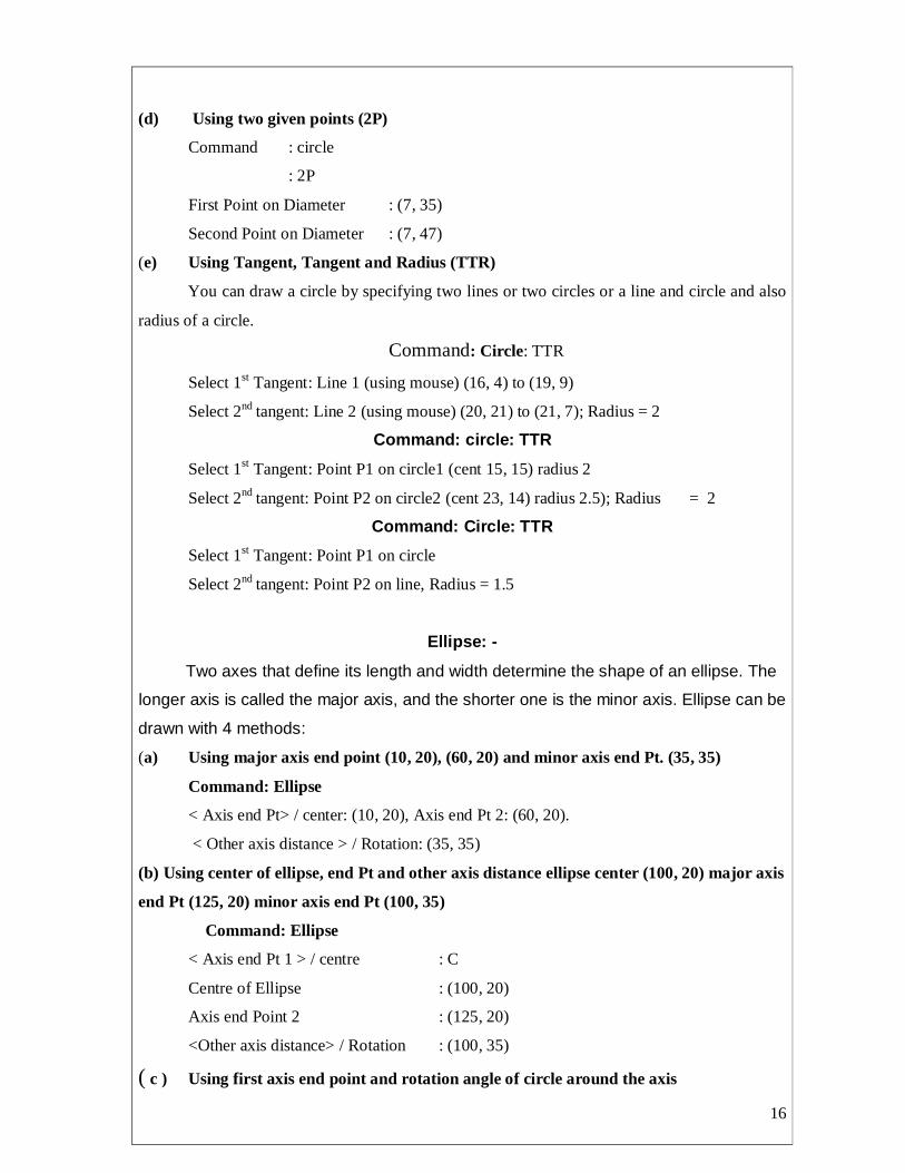
(d) Using two given points (2P)
Command : circle
: 2P
First Point on Diameter : (7, 35)
Second Point on Diameter : (7, 47)
(e) Using Tangent, Tangent and Radius (TTR)
You can draw a circle by specifying two lines or two circles or a line and circle and also
radius of a circle.
Command: Circle: TTR
Select 1st Tangent: Line 1 (using mouse) (16, 4) to (19, 9)
Select 2nd tangent: Line 2 (using mouse) (20, 21) to (21, 7); Radius = 2
Command: circle: TTR
Select 1st Tangent: Point P1 on circle1 (cent 15, 15) radius 2
Select 2nd tangent: Point P2 on circle2 (cent 23, 14) radius 2.5); Radius = 2
Command: Circle: TTR Select 1st Tangent: Point P1 on circle
Select 2nd tangent: Point P2 on line, Radius = 1.5
Ellipse: -
Two axes that define its length and width determine the shape of an ellipse. The
longer axis is called the major axis, and the shorter one is the minor axis. Ellipse can be
drawn with 4 methods:
(a) Using major axis end point (10, 20), (60, 20) and minor axis end Pt. (35, 35)
Command: Ellipse
< Axis end Pt> / center: (10, 20), Axis end Pt 2: (60, 20).
< Other axis distance > / Rotation: (35, 35)
(b) Using center of ellipse, end Pt and other axis distance ellipse center (100, 20) major axis
end Pt (125, 20) minor axis end Pt (100, 35)
Command: Ellipse
< Axis end Pt 1 > / centre : C
Centre of Ellipse : (100, 20)
Axis end Point 2 : (125, 20)
<Other axis distance> / Rotation : (100, 35)
( c ) Using first axis end point and rotation angle of circle around the axis
17
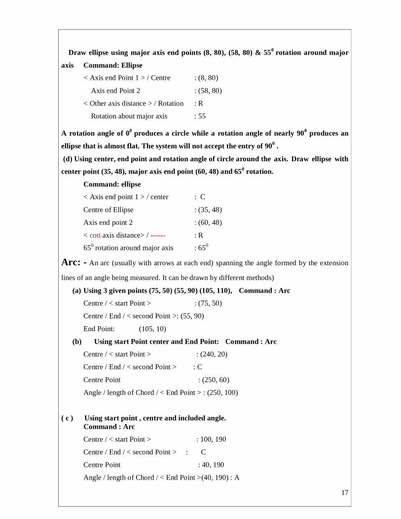
Draw ellipse using major axis end points (8, 80), (58, 80) & 550 rotation around major
axis Command: Ellipse
< Axis end Point 1 > / Centre : (8, 80)
Axis end Point 2 : (58, 80)
< Other axis distance > / Rotation : R
Rotation about major axis : 55
A rotation angle of 00 produces a circle while a rotation angle of nearly 900 produces an
ellipse that is almost flat. The system will not accept the entry of 900 .
(d) Using center, end point and rotation angle of circle around the axis. Draw ellipse with
center point (35, 48), major axis end point (60, 48) and 650 rotation.
Command: ellipse
< Axis end point 1 > / center : C
Centre of Ellipse : (35, 48)
Axis end point 2 : (60, 48)
< cott axis distance> / ------ : R
650 rotation around major axis : 650
Arc: - An arc (usually with arrows at each end) spanning the angle formed by the extension
lines of an angle being measured. It can be drawn by different methods)
(a) Using 3 given points (75, 50) (55, 90) (105, 110), Command : Arc
Centre / < start Point > : (75, 50)
Centre / End / < second Point >: (55, 90)
End Point: (105, 10)
(b) Using start Point center and End Point: Command : Arc
Centre / < start Point > : (240, 20)
Centre / End / < second Point > : C
Centre Point : (250, 60)
Angle / length of Chord / < End Point > : (250, 100)
( c ) Using start point , centre and included angle. Command : Arc
Centre / < start Point > : 100, 190
Centre / End / < second Point > : C
Centre Point : 40, 190
Angle / length of Chord / < End Point >(40, 190) : A
18
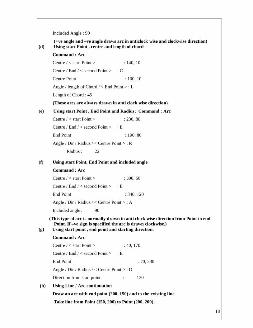
Included Angle : 90
(+ve angle and –ve angle draws arc in anticlock wise and clockwise direction) (d) Using start Point , centre and length of chord
Command : Arc
Centre / < start Point > : 140, 10
Centre / End / < second Point > : C
Centre Point : 100, 10
Angle / length of Chord / < End Point > : L
Length of Chord : 45
(These arcs are always drawn in anti clock wise direction)
(e) Using start Point , End Point and Radius; Command : Arc
Centre / < start Point > : 230, 80
Centre / End / < second Point > : E
End Point : 190, 80
Angle / Dir / Radius / < Centre Point > : R
Radius : 22
(f) Using start Point, End Point and included angle
Command : Arc
Centre / < start Point > : 300, 60
Centre / End / < second Point > : E
End Point : 340, 120
Angle / Dir / Radius / < Centre Point > : A
Included angle : 90
(This type of arc is normally drawn in anti clock wise direction from Point to end Point. If –ve sign is specified the arc is drawn clockwise.)
(g) Using start point , end point and starting direction.
Command : Arc
Centre / < start Point > : 40, 170
Centre / End / < second Point > : E
End Point : 70, 230
Angle / Dir / Radius / < Centre Point > : D
Direction from start point : 120
(h) Using Line / Arc continuation
Draw an arc with end point (200, 150) and to the existing line.
Take line from Point (150, 200) to Point (200, 200);
19
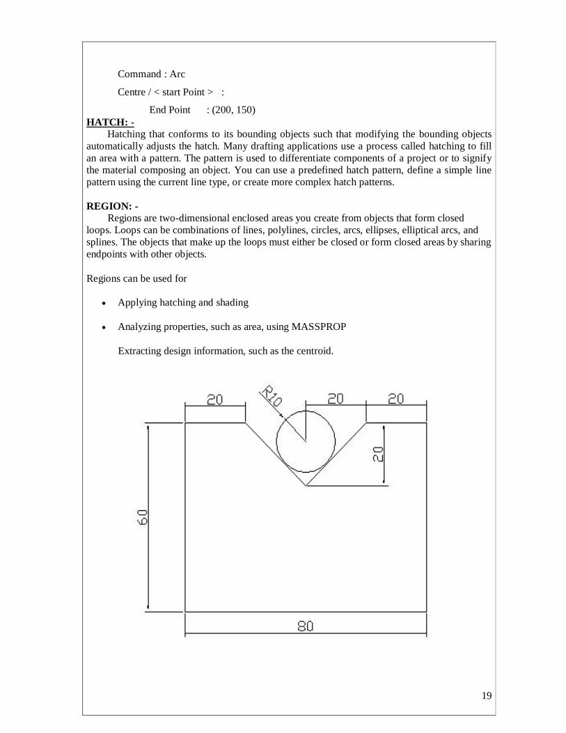
Command : Arc
Centre / < start Point > :
End Point : (200, 150) HATCH: - Hatching that conforms to its bounding objects such that modifying the bounding objects automatically adjusts the hatch. Many drafting applications use a process called hatching to fill an area with a pattern. The pattern is used to differentiate components of a project or to signify the material composing an object. You can use a predefined hatch pattern, define a simple line pattern using the current line type, or create more complex hatch patterns. REGION: - Regions are two-dimensional enclosed areas you create from objects that form closed loops. Loops can be combinations of lines, polylines, circles, arcs, ellipses, elliptical arcs, and splines. The objects that make up the loops must either be closed or form closed areas by sharing endpoints with other objects.
Regions can be used for
Applying hatching and shading
Analyzing properties, such as area, using MASSPROP
Extracting design information, such as the centroid.
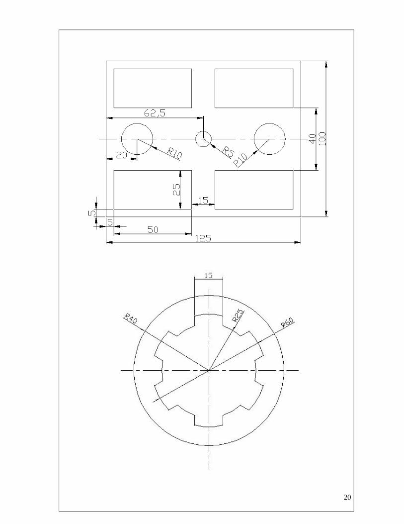
20
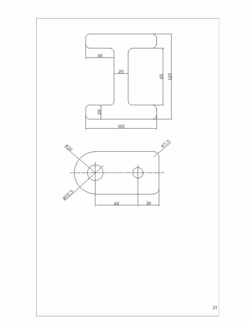
21
22
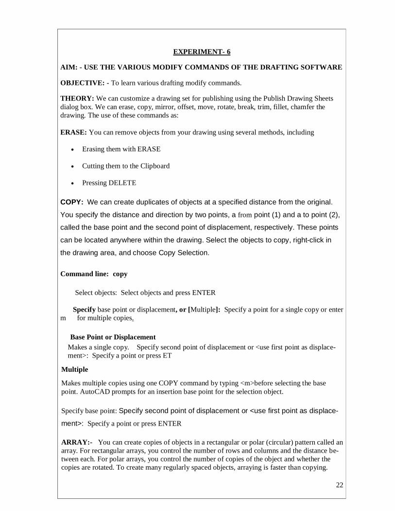
EXPERIMENT- 6
AIM: - USE THE VARIOUS MODIFY COMMANDS OF THE DRAFTING SOFTWARE
OBJECTIVE: - To learn various drafting modify commands.
THEORY: We can customize a drawing set for publishing using the Publish Drawing Sheets dialog box. We can erase, copy, mirror, offset, move, rotate, break, trim, fillet, chamfer the drawing. The use of these commands as:
ERASE: You can remove objects from your drawing using several methods, including
Erasing them with ERASE
Cutting them to the Clipboard
Pressing DELETE
COPY: We can create duplicates of objects at a specified distance from the original. You specify the distance and direction by two points, a from point (1) and a to point (2), called the base point and the second point of displacement, respectively. These points can be located anywhere within the drawing. Select the objects to copy, right-click in the drawing area, and choose Copy Selection.
Command line: copy
Select objects: Select objects and press ENTER
Specify base point or displacement, or [Multiple]: Specify a point for a single copy or enter m for multiple copies.
Base Point or Displacement Makes a single copy. Specify second point of displacement or <use first point as displace-ment>: Specify a point or press ET
Multiple
Makes multiple copies using one COPY command by typing <m>before selecting the base point. AutoCAD prompts for an insertion base point for the selection object.
Specify base point: Specify second point of displacement or <use first point as displace-ment>: Specify a point or press ENTER
ARRAY:- You can create copies of objects in a rectangular or polar (circular) pattern called an array. For rectangular arrays, you control the number of rows and columns and the distance be-tween each. For polar arrays, you control the number of copies of the object and whether the copies are rotated. To create many regularly spaced objects, arraying is faster than copying.
23
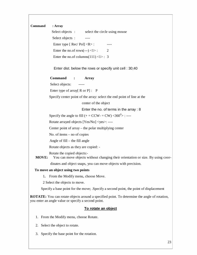
Command : Array
Select objects : select the circle using mouse
Select objects : ----
Enter type [ Rec/ Pol] <R> : ----
Enter the no.of rows(---) <1> : 2
Enter the no.of columns(111) <1> : 3
Enter dist. below the rows or specify unit cell : 30;40
Command : Array
Select objects: -----
Enter type of array[ R or P] : P
Specify center point of the array: select the end point of line at the
center of the object
Enter the no. of terms in the array : 8
Specify the angle to fill (+ = CCW- = CW) <3600> : ----
Rotate arrayed objects [Yes/No] <yes>: ----
Center point of array – the polar multiplying center
No. of items – no of copies
Angle of fill – the fill angle
Rotate objects as they are copied: -
Rotate the copied objects:- MOVE: You can move objects without changing their orientation or size. By using coor-
dinates and object snaps, you can move objects with precision.
To move an object using two points
1. From the Modify menu, choose Move.
2 Select the objects to move.
Specify a base point for the move; .Specify a second point, the point of displacement
ROTATE: You can rotate objects around a specified point. To determine the angle of rotation, you enter an angle value or specify a second point.
To rotate an object
1. From the Modify menu, choose Rotate.
2. Select the object to rotate.
3. Specify the base point for the rotation.
24
4 Enter the angle of rotation.
5 Drag the object around its base point and specify a point location to which you want to rotate.
TRIM:
We can shorten or lengthen objects to meet the edges of other objects. We also can trim objects so that they end precisely at boundary edges defined by other objects. Cutting edges can be lines, arcs, circles, polylines, ellipses, splines, regions, blocks, and rays.
To trim an object: :
1. From the Modify menu, choose Trim.
2. Select the objects to serve as cutting edges.
To select all objects in the drawing as potential cutting edges, press ENTER without se-lecting any objects. Select the objects to trim.
AutoCAD converts a circle to an arc by removing a piece of the circle starting counter-clockwise from the first to the second point.
FILLET:- You can change objects to meet in rounded or flattened corners. You can also create gaps in objects. Filleting connects two objects with a smoothly fitted arc of a specified radius.
To set the fillet radius
1. From the Modify menu, choose Fillet.
2. Enter r (Radius).
3. Enter the fillet radius
Select the objects to fillet:
CHAMFER: It is a fast way of creating a line between two nonparallel lines. It is usually used to represent a beveled edge on a corner. CHAMFER can also be used to bevel all corners of a polyline. You can chamfer lines, polylines, and rays
Command: chamfer
(TRIM mode) Current chamfer Dist1 = current, Dist2 = current
Select first line or [Polyline /Distance/Angle/Trim/Method/multiple]:
Select the second line:----------------------; The object will be chamfered at the given dis-tance:
25
26
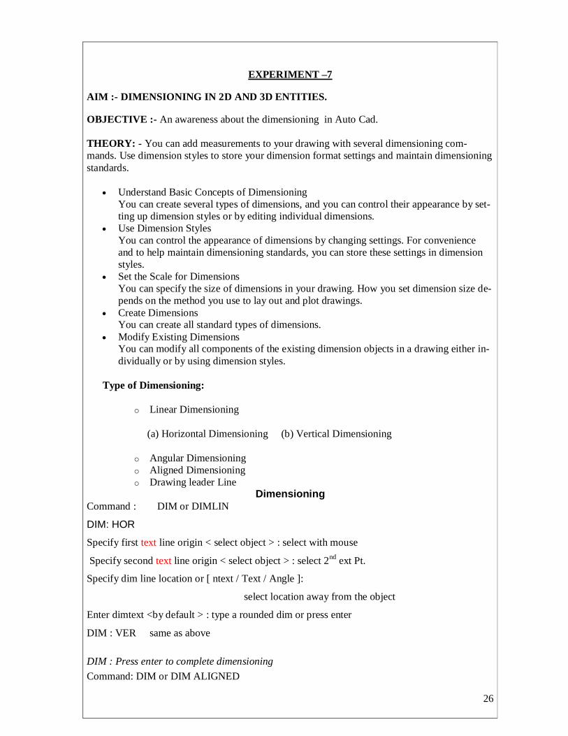
EXPERIMENT –7
AIM :- DIMENSIONING IN 2D AND 3D ENTITIES.
OBJECTIVE :- An awareness about the dimensioning in Auto Cad.
THEORY: - You can add measurements to your drawing with several dimensioning com-mands. Use dimension styles to store your dimension format settings and maintain dimensioning standards.
Understand Basic Concepts of Dimensioning You can create several types of dimensions, and you can control their appearance by set-ting up dimension styles or by editing individual dimensions.
Use Dimension Styles You can control the appearance of dimensions by changing settings. For convenience and to help maintain dimensioning standards, you can store these settings in dimension styles.
Set the Scale for Dimensions You can specify the size of dimensions in your drawing. How you set dimension size de-pends on the method you use to lay out and plot drawings.
Create Dimensions You can create all standard types of dimensions.
Modify Existing Dimensions You can modify all components of the existing dimension objects in a drawing either in-dividually or by using dimension styles.
Type of Dimensioning:
o Linear Dimensioning
(a) Horizontal Dimensioning (b) Vertical Dimensioning
o Angular Dimensioning o Aligned Dimensioning o Drawing leader Line
Dimensioning Command : DIM or DIMLIN
DIM: HOR
Specify first text line origin < select object > : select with mouse
Specify second text line origin < select object > : select 2nd ext Pt.
Specify dim line location or [ ntext / Text / Angle ]:
select location away from the object
Enter dimtext <by default > : type a rounded dim or press enter
DIM : VER same as above
DIM : Press enter to complete dimensioning Command: DIM or DIM ALIGNED
27
DIM: ALIGNED Same as above
Command : DIM: ANGULAR
Select arc, circular line or < specify vertex> : select 1st line
Select 2nd line : select 2nd
Specify dimension arc line location [M Text / Text / Angle]: specify location
Leader Line. If we want to draw a dimensioning of a number of object of same size, then we use
the Leader Line. For example, there are 10 holes in a block of 10mm diameter, then the dimen-
sioning of that case for a hole is considered for all holes.
DIM: LEADER or lea
Start point of a line
Endpoint of line
Type the text according to size of object.
28
EXPERIMENT – 8
AIM :- DRAW THE DIFFERENT TYPES OF 3D MODELLING ENTITIES USING VIEW-ING COMMANDS, TO VIEW THEM (ISOMETRIC PROJECTION).
OBJECTIVE :- An awareness about 3D isometric projection THEORY:- Isometric Projection are used for better visualization of an object The isometric axes as discussed in isomeric projection are used to draw isometric drawing but curves and el-lipse in isometric drawing are drawn in isometric planes. 3-D MODELLING ENTITIES:
Although 3D models can be more difficult and time-consuming to create than 3D views of 2D objects, 3D modeling has several advantages. You can
View the model from any vantage point
Generate reliable standard and auxiliary 2D views automatically Create 2D profiles ( SOLPROF) Remove hidden lines and do realistic shading Check interference Export the model to create an animation Do engineering analysis
Extract manufacturing data
AutoCAD supports three types of 3D modeling: wire frame, surface, and solid. Each type has its own creation and editing techniques. Wire frame Modeling
A wire frame model is a skeletal description of a 3D object. There are no surfaces in a wire frame model; it consists only of points, lines, & curves that describe the edges of the object. With AutoCAD you can create wire frame
Methods for Creating Wire frame Models
With AutoCAD you can create wire frame models by positioning any 2D planar object an-ywhere in 3D space, using several methods:
Entering 3D coordinates. You enter coordinates that define the X, Y, and Z location of the object.
Setting the default construction plane (XY plane) on which you will draw the object by defining a UCS.
Moving or copying the object to its proper 3D location after you create it.
Wire frame modeling is a skill that requires practice and experience. The best approach to learning how to create wire frame models is to begin with simple models before attempting models that are more complex. Surface modeling:
29
Surface modeling is more sophisticated than wire frame modeling in that it defines not on-ly the edges of a 3D object, but also its surfaces. The AutoCAD surface modeler defines faceted surfaces using a polygonal mesh. Because the faces of the mesh are planar, the mesh can only approximate curved surfaces. With Mechanical Desktop®, you can create true curved surfaces. To differentiate these two types of surfaces, AutoCAD calls faceted surfaces, meshes. Create 3D Solids
A block is one or more objects combined to create a single object. Blocks help you reuse objects in the same drawing or in other drawings.
Solid modeling: Solid modeling is the easiest type of 3D modeling to use. With the AutoCAD solid modeler, you can make 3D objects by creating basic 3D shapes: boxes, cones, cylinders, spheres, wedges, and donuts. You can then combine these shapes to create more complex solids by joining or subtracting them or finding their intersecting (overlapping) volume. You can also create solids by sweeping a 2D object along a path or revolving it about an axis. With Mechani-cal Desktop, you can also define solids parametrically and maintain associativity between 3D models and the 2D views that you generate from them. Some 3D modeling commands which are using to viewing projection
You can view the parallel projection of a 3D model from any point in model space.
Overview of Viewing Parallel Projections in 3D Choose Preset 3D Views
You can select predefined standard orthographic and isometric views by name or de-scription.
Define a 3D View with Coordinate Values or Angles You can define a viewing direction by entering the coordinate values of a point or the measures of two angles of rotation.
Change to a View of the XY Plane You can change the current viewpoint to a plan view of the current UCS.
Objects in 3D have thickness or elevation along the Z axis.
Add Extruded Thickness to Objects Thickness is a property of objects that simulates surfaces.
Create Wire frame Models A wireframe model is an edge or skeletal representation of a 3D object using lines and curves.
Create Surfaces A mesh represents an object's surface using planar facets.
30
EXPERIMENT –9
AIM: - SECTIONING OF SOLID PRIMITIVES AND RENDERING IN 3D
OBJECTIVE: - An awareness about sectioning and rendering 3D in Auto Cad.
THEORY: - With SECTION, you can create a cross section through a solid as a region or an anonymous block. The default method is specifying three points to define the plane. Other me-thods define the cross-sectional plane by another object, the current view, the Z axis, or the XY, YZ, or ZX plane. AutoCAD places the cross-sectional plane on the current layer.
With SLICE, you can create a new solid by cutting the existing solid and remov-ing a specified side. You can retain one or both halves of the sliced solids. The sliced solids re-tain the layer and color properties of the original solids. The default method of slicing a solid is to specify three points that define the cutting plane and then select which side to retain. You can also define the cutting plane by using another object, the current view, the Z axis, or the XY, YZ, or ZX plane.
To create a cross section of a solid
1. From the Draw menu, choose Solids &select Section.
2. Select the objects to cross-section.
3. Specify three points to define the cross-sectional plane.
The first point defines the origin (0,0,0) of the cutting plane. The second point defines the X axis, and the third point defines the Y axis.
Command line: section
Select objects: Use an object selection method & press ENTER when you finish
Specify first point on Section plane by [Object/Z-axis/View/XY/YZ/ZX] <3points>: Specify a point or enter an option
Note: If you are applying hatching to the cross-sectional cutting plane, you must align the UCS with the cross-sectional cutting plane first. RENDERING: Creates a photo realistic or realistically shaded image of a three-dimensional wire frame or solid mode
To render a model
1. Display a 3D view of your model.
2. From the View menu, choose Render.
31
3. In the Render dialog box, set options or accept the defaults. 4. Under Rendering Options, select Smooth Shading to smooth the edges between the poly-
gon faces.
Related to Smooth Shading is Smoothing Angle, which sets the angle at which Auto-CAD interprets an edge. The default angle setting is 45 degrees. Angles less than 45 degrees are smoothed; angles greater than 45 degrees are considered edges.
4. To render the image to the screen, make sure that Destination is set to Render Window or View port.
5. Select a named scene or the current view.
6. Choose Render.
Depending on the size of the drawing, after a short or long pause AutoCAD displays a rendered image of your model. Note: If your objects are zoomed out past the limits of the drawing and you are having rendering problems, try scaling the scene or zooming in to at least the limits of the draw-ing.
After creating a rendering, you can save the image for redisplay at a later time. Rendering can be a time-consuming process, but redisplaying a previously rendered image is instantaneous.
To save a rendered image, you can render directly to a file, or you can render to the screen and then save the image
32
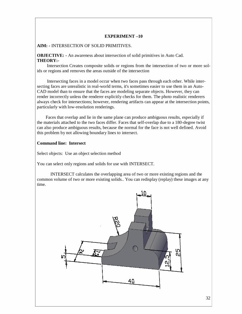
EXPERIMENT –10
AIM: - INTERSECTION OF SOLID PRIMITIVES.
OBJECTIVE: - An awareness about intersection of solid primitives in Auto Cad. THEORY:- Intersection Creates composite solids or regions from the intersection of two or more sol-ids or regions and removes the areas outside of the intersection
Intersecting faces in a model occur when two faces pass through each other. While inter-secting faces are unrealistic in real-world terms, it's sometimes easier to use them in an Auto-CAD model than to ensure that the faces are modeling separate objects. However, they can render incorrectly unless the renderer explicitly checks for them. The photo realistic renderers always check for intersections; however, rendering artifacts can appear at the intersection points, particularly with low-resolution renderings.
Faces that overlap and lie in the same plane can produce ambiguous results, especially if the materials attached to the two faces differ. Faces that self-overlap due to a 180-degree twist can also produce ambiguous results, because the normal for the face is not well defined. Avoid this problem by not allowing boundary lines to intersect.
Command line: Intersect
Select objects: Use an object selection method
You can select only regions and solids for use with INTERSECT.
INTERSECT calculates the overlapping area of two or more existing regions and the common volume of two or more existing solids.. You can redisplay (replay) these images at any time.


![CG Lab Manual[1]](https://img.pdfslide.us/doc/110x75/553360824a79593a568b493c/cg-lab-manual1.jpg)