Embed Size (px)
Citation preview
Cisco Connected Grid 2G/3G/4G Multimode LTE GRWIC Installation and Configuration Guide
First Published: November, 2011OL-25668-01
This document provides an overview of hardware and configuration information for Cisco Connected Grid 2G/3G/4G Multimode LTE (Long-Term Evolution) GRWIC, a single-wide grid router WAN interface card supported on Cisco 2010 Connected Grid Router (CGR).
This document covers the following topics:
• Feature History, page 1
• Hardware Overview, page 3
• Installing the SIM Card, page 10
• Installing and Removing the Module, page 12
• Regulatory and Compliance Information, page 15
• Software Overview, page 15
• Configuring the Module, page 17
• Configuration Examples, page 27
• Troubleshooting and Diagnostics, page 31
• Additional References, page 39
• Tell Us What You Think, page 40
Feature HistoryCisco Feature Navigator provides information about platform support, software image support, including software image and their supported software release, feature set, or platform.
You can access Cisco Feature Navigator, by going to http://www.cisco.com/go/cfn. An account on Cisco.com is not required.
Americas Headquarters:Cisco Systems, Inc., 170 West Tasman Drive, San Jose, CA 95134-1706 USA
Features
Table 1 lists the release history for this feature.
Note Table 1 lists only the software release that introduced support for a given feature in a given software release train. Unless noted otherwise, subsequent releases of that software release train also support that feature.
FeaturesThe 4G GRWIC offers the following key features:
• Supports the Cisco 2010 Connected Grid Router
• Primary cellular WAN connection for critical data applications in support of the Cisco 2010 Connected Grid Router
• WAN connectivity as a backup datalink for critical data applications
• Sierra Wireless MC7750, MC7700, or MC7710 modems
The 4G GRWIC supports the following:
• IPv4 bearer
• MIPv4, NEMOv4
• IPv4 subnet behind LTE UE interface
• Enhanced High Rate Packet Data (eHRPD) for seamless handoff between LTE and 3G services
• Remote access to Qualcomm Diagnostic Monitor (DM) port
• OTA-DM including wireless configuration FOTA
• RFC 3025—Mobile IP vendor/organization on specific extension
• Single UICC (USIM)
Table 1 Feature Information for 4G GRWIC
Feature Name Releases Feature Information
Multimode Long Term Evolution (LTE) Support for CGR
15.2(2)T 4G GRWIC supports 4G-LTE cellular and 3G cellular networks. 4G-LTE mobile specification provides multi-megabit bandwidth, more efficient use of the radio network, latency reduction, and improved mobility.
This feature was introduced for the Cisco 2010 Connected Grid Router.
2Cisco Connected Grid 2G/3G/4G Multimode LTE GRWIC Installation and Configuration Guide
OL-25668-01
Hardware Overview
Hardware OverviewThe 4G GRWIC is a cellular modem interface card for the Cisco 2010 Connected Grid Router that provides a primary wireless WAN data link interface over a cellular network. It is a High-Speed Packet Access (HSPA) multiband, multiservice, single-wide GRWIC allowing transmission and distribution communication between utilities and substations through 4G technologies. The module is backward-compatible with previous generation technologies and frequency bands.
This section cover the following topics:
• RF Specifications, page 4
• Multimode Modem, page 4
• Envrionmental Specifications, page 5
• Memory Specifications, page 6
• Kit Contents, page 7
• Ports and LEDs, page 7
• Supported Cisco Antennas and Cables by Case, page 9
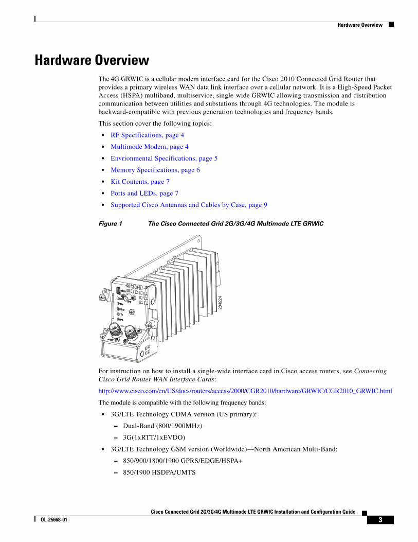
Figure 1 The Cisco Connected Grid 2G/3G/4G Multimode LTE GRWIC
For instruction on how to install a single-wide interface card in Cisco access routers, see Connecting Cisco Grid Router WAN Interface Cards:
http://www.cisco.com/en/US/docs/routers/access/2000/CGR2010/hardware/GRWIC/CGR2010_GRWIC.html
The module is compatible with the following frequency bands:
• 3G/LTE Technology CDMA version (US primary):
– Dual-Band (800/1900MHz)
– 3G(1xRTT/1xEVDO)
• 3G/LTE Technology GSM version (Worldwide)—North American Multi-Band:
– 850/900/1800/1900 GPRS/EDGE/HSPA+
– 850/1900 HSDPA/UMTS
2842
24
3Cisco Connected Grid 2G/3G/4G Multimode LTE GRWIC Installation and Configuration Guide
OL-25668-01
Hardware Overview
• 3G/LTE Technology GSM version (Worldwide)—European Union (EU) Multi-Band:
– 900/1800/1900 GPRS/EDGE/HSPA+
– 2100 HSDPA/UMTS
RF SpecificationsThe following are additional 4G specifications of the card:
• 4G/LTE Technology CDMA, 700 MHz (US primary)
• 3G, 1xRTT/1xEVDO, dual-band 800/1900 MHz
Multimode ModemThe 4G GRWIC comes with a Sierra Wireless multi-mode modem that provides the RF interface for the modem. The modem complies with PCI Express Mini Card Electromechanical Specification, revision 1.2. The hardware includes the following:
• Multiple LED indicates modem status, service, and signal strength
• A single Subscriber Identity Module (SIM)
The modem supports one of the following standards:
• 3G Evolution-Data Optimized (EVDO or DOrA) Mode—EVDO is a 3G telecommunications standard for the wireless transmission of data through radio signals, typically for broadband Internet access. EVDO uses multiplexing techniques including code division multiple access (CDMA) as well as time division multiple access (TDMA) to maximize both individual users' throughput and the overall system throughput.
Note Code Division Multiple Access (CDMA) is a method of dividing a radio spectrum to be shared by multiple users through the assignment of unique codes. CDMA implements spread spectrum transmission.
Note Time Division Multiplex Access (TDMA) is a type of multiplexing where two or more channels of information are transmitted over the same link by allocating a different time interval ("slot" or "slice") for the transmission of each channel; that is, the channels take turns to use the link. Some kind of periodic synchronizing signal or distinguishing identifier usually is required so that the receiver can tell which channel is which.
• 4G-LTE— Designated as a fourth-generation (4G) mobile specification, LTE is designed to provide multi-megabit bandwidth, more efficient use of the radio network, latency reduction, and improved mobility. This combination aims to enhance the subscriber's interaction with the network and further drive the demand for mobile multimedia services.
Sierra Wireless AirPrime MC7700, MC7750, and MC7710 modules each deliver up to 100 Mbps download speeds and 50 Mbps upload speeds (within 20 MHz bandwidth), integrated GPS capabilities, and support for both Linux and Windows.
4Cisco Connected Grid 2G/3G/4G Multimode LTE GRWIC Installation and Configuration Guide
OL-25668-01
Hardware Overview
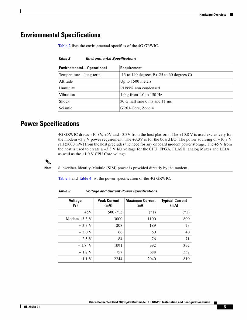
Envrionmental SpecificationsTable 2 lists the environmental specifics of the 4G GRWIC.
Power Specifications4G GRWIC draws +10.8V, +5V and +3.3V from the host platform. The +10.8 V is used exclusively for the modem +3.3 V power requirement. The +3.3V is for the board I/O. The power sourcing of +10.8 V rail (5000 mW) from the host precludes the need for any onboard modem power storage. The +5 V from the host is used to create a +3.3 V I/O voltage for the CPU, FPGA, FLASH, analog Muxes and LEDs, as well as the +1.0 V CPU Core voltage.
Note Subscriber-Identity-Module (SIM) power is provided directly by the modem.
Table 3 and Table 4 list the power specification of the 4G GRWIC.
Table 2 Environmental Specifications
Environmental—Operational Requirement
Temperature—long term -13 to 140 degrees F (-25 to 60 degrees C)
Altitude Up to 1500 meters
Humidity RH95% non condensed
Vibration 1.0 g from 1.0 to 150 Hz
Shock 30 G half sine 6 ms and 11 ms
Seismic GR63-Core, Zone 4
Table 3 Voltage and Current Power Specifications
Voltage(V)
Peak Current(mA)
Maximum Current(mA)
Typical Current(mA)
+5V 500 (*1) (*1) (*1)
Modem +3.3 V 3000 1100 800
+ 3.3 V 208 189 73
+ 3.0 V 66 60 40
+ 2.5 V 84 76 71
+ 1.8 V 1091 992 392
+ 1.2 V 757 688 352
+ 1.1 V 2244 2040 810
5Cisco Connected Grid 2G/3G/4G Multimode LTE GRWIC Installation and Configuration Guide
OL-25668-01
Hardware Overview
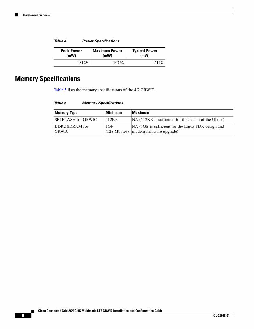
Memory SpecificationsTable 5 lists the memory specifications of the 4G GRWIC.
Table 4 Power Specifications
Peak Power(mW)
Maximum Power(mW)
Typical Power(mW)
18129 10732 5118
Table 5 Memory Specifications
Memory Type Minimum Maximum
SPI FLASH for GRWIC 512KB NA (512KB is sufficient for the design of the Uboot)
DDR2 SDRAM for GRWIC
1Gb (128 Mbytes)
NA (1GB is sufficient for the Linux SDK design and modem firmware upgrade)
6Cisco Connected Grid 2G/3G/4G Multimode LTE GRWIC Installation and Configuration Guide
OL-25668-01
Hardware Overview
Kit ContentsCisco Connected Grid 2G/3G/4G Multimode LTE GRWIC is a customer-replaceable unit and can be ordered by referencing the following information.
Table 6 describes the Cisco 4G WWAN GRWIC product SKUs.
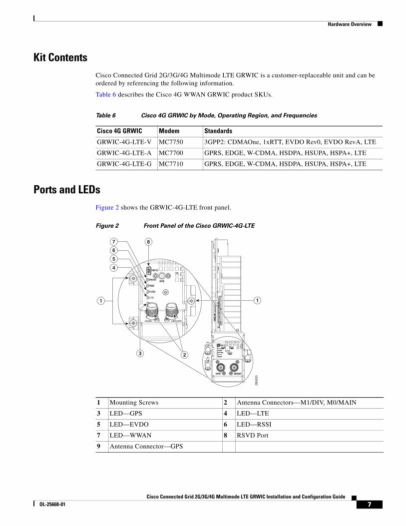
Ports and LEDsFigure 2 shows the GRWIC-4G-LTE front panel.
Figure 2 Front Panel of the Cisco GRWIC-4G-LTE
Table 6 Cisco 4G GRWIC by Mode, Operating Region, and Frequencies
Cisco 4G GRWIC Modem Standards
GRWIC-4G-LTE-V MC7750 3GPP2: CDMAOne, 1xRTT, EVDO Rev0, EVDO RevA, LTE
GRWIC-4G-LTE-A MC7700 GPRS, EDGE, W-CDMA, HSDPA, HSUPA, HSPA+, LTE
GRWIC-4G-LTE-G MC7710 GPRS, EDGE, W-CDMA, HSDPA, HSUPA, HSPA+, LTE
1 Mounting Screws 2 Antenna Connectors—M1/DIV, M0/MAIN
3 LED—GPS 4 LED—LTE
5 LED—EVDO 6 LED—RSSI
7 LED—WWAN 8 RSVD Port
9 Antenna Connector—GPS
2836
33
3 2
1
8
4
5
6
7
1
7Cisco Connected Grid 2G/3G/4G Multimode LTE GRWIC Installation and Configuration Guide
OL-25668-01
Hardware Overview
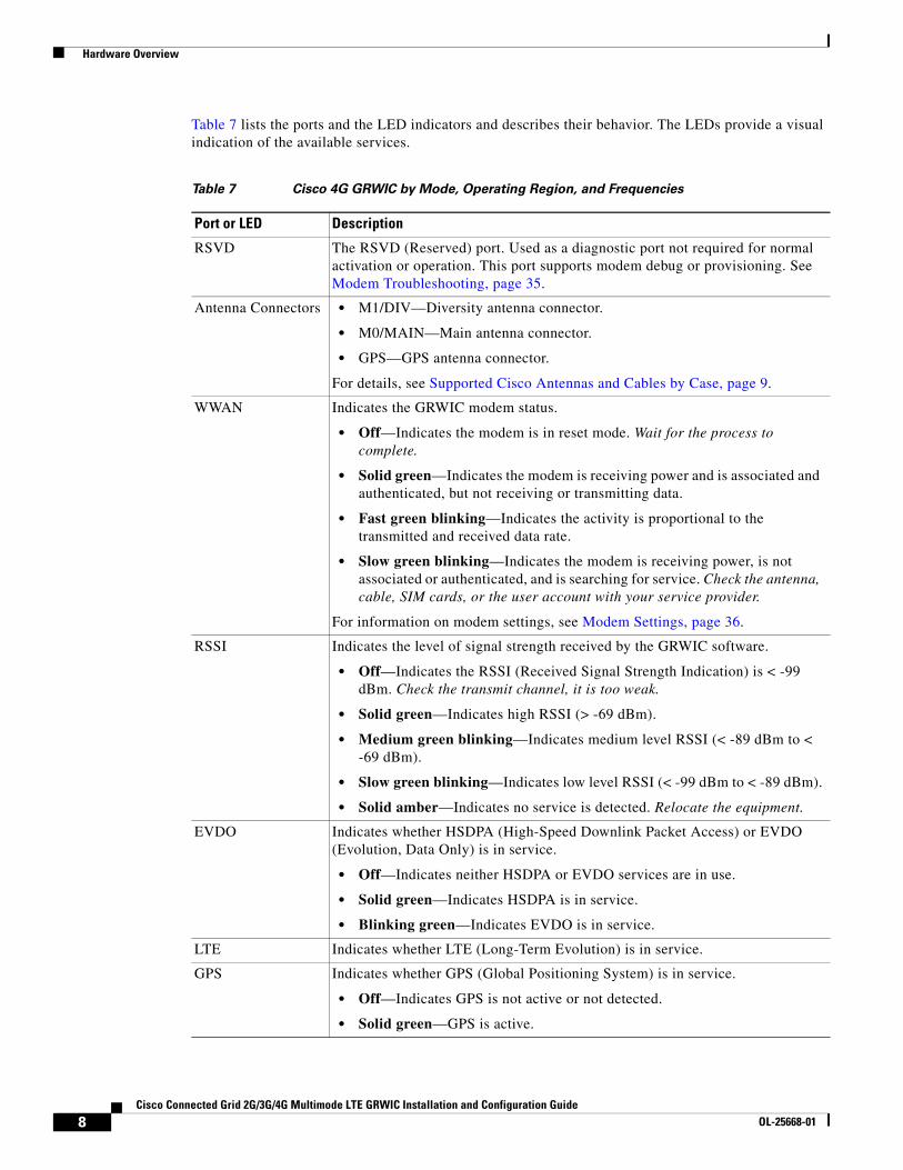
Table 7 lists the ports and the LED indicators and describes their behavior. The LEDs provide a visual indication of the available services.
Table 7 Cisco 4G GRWIC by Mode, Operating Region, and Frequencies
Port or LED Description
RSVD The RSVD (Reserved) port. Used as a diagnostic port not required for normal activation or operation. This port supports modem debug or provisioning. See Modem Troubleshooting, page 35.
Antenna Connectors • M1/DIV—Diversity antenna connector.
• M0/MAIN—Main antenna connector.
• GPS—GPS antenna connector.
For details, see Supported Cisco Antennas and Cables by Case, page 9.
WWAN Indicates the GRWIC modem status.
• Off—Indicates the modem is in reset mode. Wait for the process to complete.
• Solid green—Indicates the modem is receiving power and is associated and authenticated, but not receiving or transmitting data.
• Fast green blinking—Indicates the activity is proportional to the transmitted and received data rate.
• Slow green blinking—Indicates the modem is receiving power, is not associated or authenticated, and is searching for service. Check the antenna, cable, SIM cards, or the user account with your service provider.
For information on modem settings, see Modem Settings, page 36.
RSSI Indicates the level of signal strength received by the GRWIC software.
• Off—Indicates the RSSI (Received Signal Strength Indication) is < -99 dBm. Check the transmit channel, it is too weak.
• Solid green—Indicates high RSSI (> -69 dBm).
• Medium green blinking—Indicates medium level RSSI (< -89 dBm to < -69 dBm).
• Slow green blinking—Indicates low level RSSI (< -99 dBm to < -89 dBm).
• Solid amber—Indicates no service is detected. Relocate the equipment.
EVDO Indicates whether HSDPA (High-Speed Downlink Packet Access) or EVDO (Evolution, Data Only) is in service.
• Off—Indicates neither HSDPA or EVDO services are in use.
• Solid green—Indicates HSDPA is in service.
• Blinking green—Indicates EVDO is in service.
LTE Indicates whether LTE (Long-Term Evolution) is in service.
GPS Indicates whether GPS (Global Positioning System) is in service.
• Off—Indicates GPS is not active or not detected.
• Solid green—GPS is active.
8Cisco Connected Grid 2G/3G/4G Multimode LTE GRWIC Installation and Configuration Guide
OL-25668-01
Hardware Overview
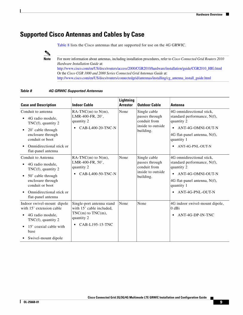
Supported Cisco Antennas and Cables by CaseTable 8 lists the Cisco antennas that are supported for use on the 4G GRWIC.
Note For more information about antennas, including installation procedures, refer to Cisco Connected Grid Routers 2010 Hardware Installation Guide at: http://www.cisco.com/en/US/docs/routers/access/2000/CGR2010/hardware/installation/guide/CGR2010_HIG.htmlOr the Cisco CGR 1000 and 2000 Series Connected Grid Antennas Guide at:http://www.cisco.com/en/US/docs/routers/connectedgrid/antennas/installing/cg_antenna_install_guide.html
Table 8 4G GRWIC Supported Antennas
Case and Description Indoor CableLightning Arrestor Outdoor Cable Antenna
Conduit to antenna
• 4G radio module, TNC(f), quantity 2
• 20’ cable through enclosure through conduit or boot
• Omnidirectional stick or flat-panel antenna
RA-TNC(m) to N(m), LMR-400-FR, 20’, quantity 2
• CAB-L400-20-TNC-N
None Single cable passes through conduit from inside to outside building.
4G omnidirectional stick, standard performance, N(f), quantity 2
• ANT-4G-OMNI-OUT-N
4G flat-panel antenna, N(f), quantity 1
• ANT-4G-PNL-OUT-N
Conduit to Antenna
• 4G radio module, TNC(f), quantity 2
• 50’ cable through enclosure through conduit or boot
• Omnidirectional stick or flat-panel antenna
RA-TNC(m) to N(m), LMR-400-FR, 50’, quantity 2
• CAB-L400-50-TNC-N
None Single cable passes through conduit from inside to outside building.
4G omnidirectional stick, standard performance, N(f), quantity 2
• ANT-4G-OMNI-OUT-N
4G flat-panel antenna, N(f), quantity 1
• ANT-4G-PNL-OUT-N
Indoor swivel-mount dipole with 15’ extension cable
• 4G radio module, TNC(f), quantity 2
• 15’ coaxial cable with base
• Swivel-mount dipole
Single-port antenna stand with 15’ cable included, TNC(m) to TNC(m), quantity 2
• CAB-L195-15-TNC
None None 4G indoor swivel-mount dipole, 0 dBi
• ANT-4G-DP-IN-TNC
9Cisco Connected Grid 2G/3G/4G Multimode LTE GRWIC Installation and Configuration Guide
OL-25668-01
Installing the SIM Card
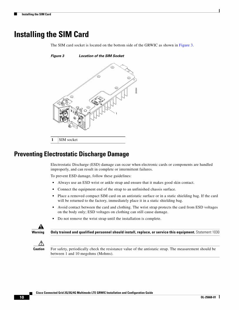
Installing the SIM CardThe SIM card socket is located on the bottom side of the GRWIC as shown in Figure 3.
Figure 3 Location of the SIM Socket
Preventing Electrostatic Discharge DamageElectrostatic Discharge (ESD) damage can occur when electronic cards or components are handled improperly, and can result in complete or intermittent failures.
To prevent ESD damage, follow these guidelines:
• Always use an ESD wrist or ankle strap and ensure that it makes good skin contact.
• Connect the equipment end of the strap to an unfinished chassis surface.
• Place a removed compact SIM card on an antistatic surface or in a static shielding bag. If the card will be returned to the factory, immediately place it in a static shielding bag.
• Avoid contact between the card and clothing. The wrist strap protects the card from ESD voltages on the body only; ESD voltages on clothing can still cause damage.
• Do not remove the wrist strap until the installation is complete.
Warning Only trained and qualified personnel should install, replace, or service this equipment. Statement 1030
Caution For safety, periodically check the resistance value of the antistatic strap. The measurement should be between 1 and 10 megohms (Mohms).
1 SIM socket28
3584
1
10Cisco Connected Grid 2G/3G/4G Multimode LTE GRWIC Installation and Configuration Guide
OL-25668-01
Installing the SIM Card
DETAILED STEPS
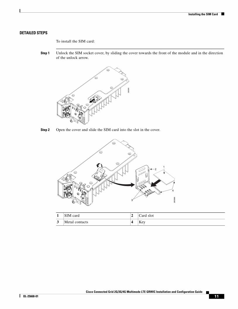
To install the SIM card:
Step 1 Unlock the SIM socket cover, by sliding the cover towards the front of the module and in the direction of the unlock arrow.
Step 2 Open the cover and slide the SIM card into the slot in the cover.
1 SIM card 2 Card slot
3 Metal contacts 4 Key
2835
85
28
35
86
2
3
1
4
11Cisco Connected Grid 2G/3G/4G Multimode LTE GRWIC Installation and Configuration Guide
OL-25668-01
Installing and Removing the Module
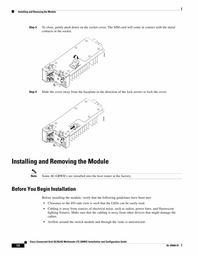
Step 3 To close, gently push down on the socket cover. The SIM card will come in contact with the metal contacts in the socket.
Step 4 Slide the cover away from the faceplate in the direction of the lock arrows to lock the cover.
Installing and Removing the Module
Note Some 4G GRWICs are installed into the host router at the factory.
Before You Begin InstallationBefore installing the module, verify that the following guidelines have been met:
• Clearance to the I/O-side view is such that the LEDs can be easily read.
• Cabling is away from sources of electrical noise, such as radios, power lines, and fluorescent lighting fixtures. Make sure that the cabling is away from other devices that might damage the cables.
• Airflow around the switch module and through the vents is unrestricted.
2835
8728
3588
12Cisco Connected Grid 2G/3G/4G Multimode LTE GRWIC Installation and Configuration Guide
OL-25668-01
Installing and Removing the Module
• Temperature around the unit does not exceed 140°F (60°C). If the switch module is installed in a closed or multirack assembly, the temperature around it might be higher than normal room temperature.
• Relative humidity around the switch module does not exceed 95 percent (noncondensing).
• Altitude at the installation site is not higher than 10,000 feet.
• For 10/100 and 10/100/1000 fixed ports, cable lengths from the switch module to connected devices are not longer than 328 feet (100 meters).
Installation Warning StatementsThis section includes the basic installation warning statements. Translations of these warning statements appear in the Regulatory Compliance and Safety Information for Cisco Connected Grid Router 1000 Series Routers documents.
Warning This unit is intended for installation in restricted access areas. A restricted access area can be accessed only through the use of a special tool, lock and key, or other means of security. Statement 1017
Warning Only trained and qualified personnel should be allowed to install, replace, or service this equipment. Statement 1030
Warning To prevent the system from overheating, do not operate it in an area that exceeds the maximum recommended ambient temperature of:140°F (60°C) Statement 1047
Warning This equipment is supplied as “open type” equipment. It must be mounted within an enclosure that is suitably designed for those specific environmental conditions that will be present and appropriately designed to prevent personal injury resulting from accessibility to live parts. The interior of the enclosure must be accessible only by the use of a tool.
The enclosure must meet IP 54 or NEMA type 4 minimum enclosure rating standards. Statement 1063
Warning This equipment is intended to be grounded to comply with emission and immunity requirements. Ensure that the switch functional ground lug is connected to earth ground during normal use. Statement 1064
Warning To prevent airflow restriction, allow clearance around the ventilation openings to be at least: 1.75 in. (4.4 cm) Statement 1076
13Cisco Connected Grid 2G/3G/4G Multimode LTE GRWIC Installation and Configuration Guide
OL-25668-01
Installing and Removing the Module
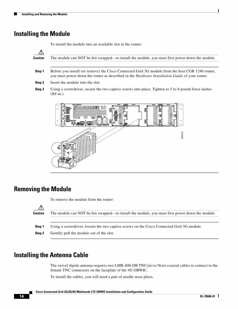
Installing the ModuleTo install the module into an available slot in the router:
Caution The module can NOT be hot swapped—to install the module, you must first power down the module.
Step 1 Before you install (or remove) the Cisco Connected Grid 3G module from the host CGR 1240 router, you must power down the router as described in the Hardware Installation Guide of your router.
Step 2 Insert the module into the slot.
Step 3 Using a screwdriver, secure the two captive screws into place. Tighten to 5 to 8 pound-force inches (lbf-in.).
Removing the ModuleTo remove the module from the router:
Caution The module can NOT be hot swapped—to install the module, you must first power down the module.
Step 1 Using a screwdriver, loosen the two captive screws on the Cisco Connected Grid 3G module.
Step 2 Gentlly pull the module out of the slot.
Installing the Antenna CableThe swivel dipole antenna requires two LMR-400-DB TNC(m) to N(m) coaxial cables to connect to the female TNC connectors on the faceplate of the 4G GRWIC.
To install the cables, you will need a pair of needle-nose pliers.
2842
31
14Cisco Connected Grid 2G/3G/4G Multimode LTE GRWIC Installation and Configuration Guide
OL-25668-01
Regulatory and Compliance Information
Step 1 Carefully position the male end of the cable connector over the female connector on the faceplate of the module so it aligns properly, i.e. directly on top of and in line with the female connector.
Step 2 Hand tighten the connectors. It is important to begin tightening the connector by hand to properly align the connectors.
Note Do not use a screwdriver on the body of the TNC connector, the screw head that is visible is not intended to be removed.
Step 3 Use a pair of needle-nose pliers to tighten the connectors until they are nearly fully secured. Before the connectors are fully tightened, position the coaxial cables in their final desired positions, then proceed to fully tighten the connectors.
Step 4 Tie-wrap the cables onto the cabinet and route toward the cable-entry point.
Note Be sure to adhere to the required bend radius of the cable.
Regulatory and Compliance InformationFor regulatory compliance and safety information for the module, refer to the Connected Grid Router 2000 Series Regulatory Compliance and Safety Information document.
http://www.cisco.com/en/US/docs/routers/access/2000/CGR2010/hardware/rcsi/rcsiCGR2000series.html
Software OverviewCisco 4G Wireless WAN GRWICs operate over Fourth Generation (4G) Long-Term Evolution (LTE) cellular networks and Third Generation (3G) cellular networks.
Overview of 4G-LTE Networks4G-LTE mobile specification provides multi-megabit bandwidth, more efficient use of the radio network, latency reduction, and improved mobility. LTE solutions target new cellular networks. These networks are designed to support up to 300 Mbps peak rates in the downlink and up to 75 Mbps peak rates in the uplink. The throughput of these networks is higher than the existing 3G networks.
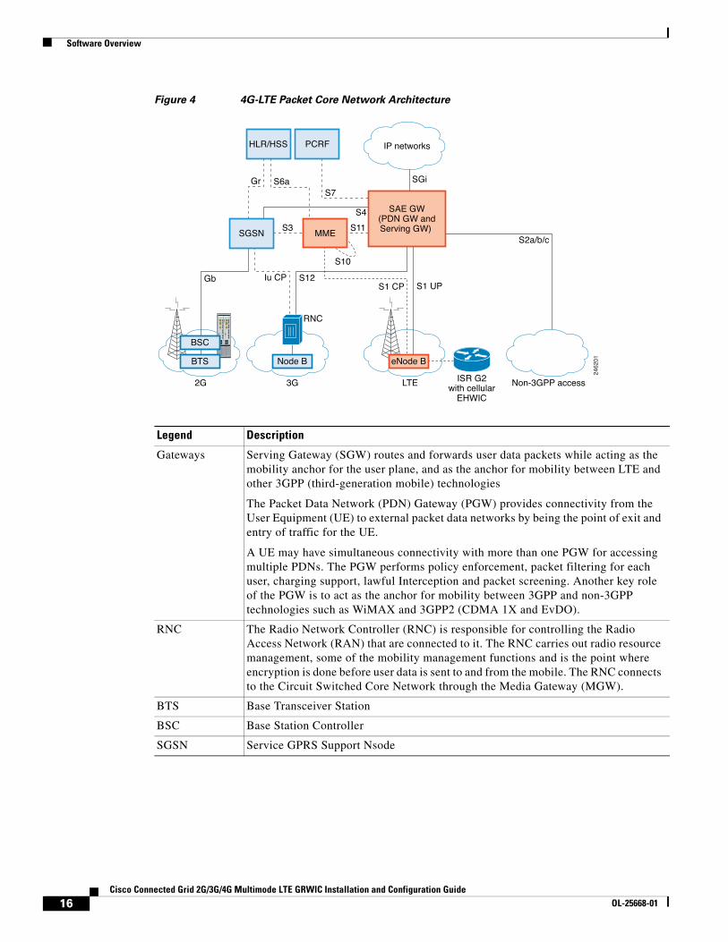
Figure 4 shows a 4G-LTE packet core network and the network elements it contains.
15Cisco Connected Grid 2G/3G/4G Multimode LTE GRWIC Installation and Configuration Guide
OL-25668-01
Software Overview
Figure 4 4G-LTE Packet Core Network Architecture
Legend Description
Gateways Serving Gateway (SGW) routes and forwards user data packets while acting as the mobility anchor for the user plane, and as the anchor for mobility between LTE and other 3GPP (third-generation mobile) technologies
The Packet Data Network (PDN) Gateway (PGW) provides connectivity from the User Equipment (UE) to external packet data networks by being the point of exit and entry of traffic for the UE.
A UE may have simultaneous connectivity with more than one PGW for accessing multiple PDNs. The PGW performs policy enforcement, packet filtering for each user, charging support, lawful Interception and packet screening. Another key role of the PGW is to act as the anchor for mobility between 3GPP and non-3GPP technologies such as WiMAX and 3GPP2 (CDMA 1X and EvDO).
RNC The Radio Network Controller (RNC) is responsible for controlling the Radio Access Network (RAN) that are connected to it. The RNC carries out radio resource management, some of the mobility management functions and is the point where encryption is done before user data is sent to and from the mobile. The RNC connects to the Circuit Switched Core Network through the Media Gateway (MGW).
BTS Base Transceiver Station
BSC Base Station Controller
SGSN Service GPRS Support Nsode
2G
S1 CP S1 UP
Non-3GPP access
Iu CPGb
S3
S12
S11
GrS7
S10
SGi
S4
S6a
S2a/b/c
SAE GW(PDN GW andServing GW)
LTE ISR G2with cellular
EHWIC
3G
RNC
Node B eNode B
IP networks
BTS
BSC
MME
HLR/HSS PCRF
SGSN
2462
01
16Cisco Connected Grid 2G/3G/4G Multimode LTE GRWIC Installation and Configuration Guide
OL-25668-01
Configuring the Module
Configuring the ModuleThis section covers the following topics:
• Prerequisites, page 17
• Configuration Restrictions, page 17
• Data Account Provisioning, page 17
• Verifying Signal Strength and Service Availability, page 18
• Data Call Setup, page 19
PrerequisitesTo configure the 4G GRWIC, you must meet the following requirements:
• Have 4G-LTE network coverage where your router will be physically located. For a complete list of supported carriers, see the product data sheet.
• Subscribe to a service plan with a wireless service provider and obtain a SIM card.
• Install the SIM card before configuring the 4G-LTE Wireless WAN GRWIC. For instructions on how to install the SIM card, see Installing the SIM Card, page 10.
Configuration RestrictionsBe aware of the following restrictions that exist with a cellular network:
• Currently, cellular networks support only outgoing calls.
• Throughput—due to the shared nature of wireless communications, the experienced throughput varies depending on the number of active users or congestion in a given network.
• Cellular networks have higher latency compared to wired networks. Latency rates depend on the technology and carrier. Latency may be higher because of network congestion.
• Any restrictions that are a part of the terms of service from your carrier.
Data Account Provisioning
Note For 4G-LTE GRWICs, the numbering for Slot 0, wic 0 and port 0 is 0/0/0 for all commands.
Note To provision your modem, you must have an active wireless account with a service provider and a SIM card installed.
To provision your data account, see the following topics:
• Verifying Signal Strength and Service Availability, page 18
• Configuring a Modem Data Profile, page 18
17Cisco Connected Grid 2G/3G/4G Multimode LTE GRWIC Installation and Configuration Guide
OL-25668-01
Configuring the Module
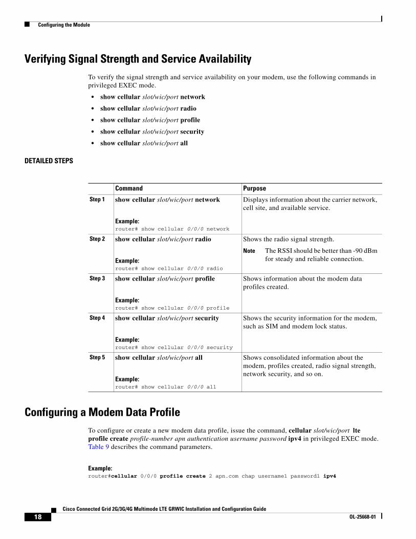
Verifying Signal Strength and Service AvailabilityTo verify the signal strength and service availability on your modem, use the following commands in privileged EXEC mode.
• show cellular slot/wic/port network
• show cellular slot/wic/port radio
• show cellular slot/wic/port profile
• show cellular slot/wic/port security
• show cellular slot/wic/port all
DETAILED STEPS
Configuring a Modem Data ProfileTo configure or create a new modem data profile, issue the command, cellular slot/wic/port lte profile create profile-number apn authentication username password ipv4 in privileged EXEC mode. Table 9 describes the command parameters.
Example:router#cellular 0/0/0 profile create 2 apn.com chap username1 password1 ipv4
Command Purpose
Step 1 show cellular slot/wic/port network
Example:router# show cellular 0/0/0 network
Displays information about the carrier network, cell site, and available service.
Step 2 show cellular slot/wic/port radio
Example:router# show cellular 0/0/0 radio
Shows the radio signal strength.
Note The RSSI should be better than -90 dBm for steady and reliable connection.
Step 3 show cellular slot/wic/port profile
Example:router# show cellular 0/0/0 profile
Shows information about the modem data profiles created.
Step 4 show cellular slot/wic/port security
Example:router# show cellular 0/0/0 security
Shows the security information for the modem, such as SIM and modem lock status.
Step 5 show cellular slot/wic/port all
Example:router# show cellular 0/0/0 all
Shows consolidated information about the modem, profiles created, radio signal strength, network security, and so on.
18Cisco Connected Grid 2G/3G/4G Multimode LTE GRWIC Installation and Configuration Guide
OL-25668-01
Configuring the Module
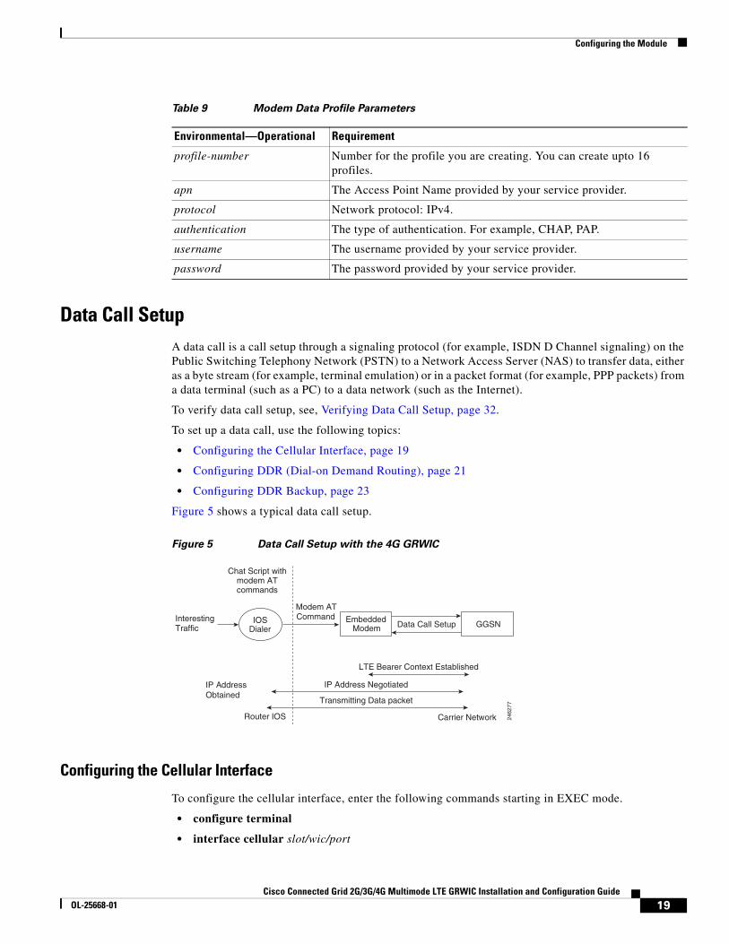
Data Call SetupA data call is a call setup through a signaling protocol (for example, ISDN D Channel signaling) on the Public Switching Telephony Network (PSTN) to a Network Access Server (NAS) to transfer data, either as a byte stream (for example, terminal emulation) or in a packet format (for example, PPP packets) from a data terminal (such as a PC) to a data network (such as the Internet).
To verify data call setup, see, Verifying Data Call Setup, page 32.
To set up a data call, use the following topics:
• Configuring the Cellular Interface, page 19
• Configuring DDR (Dial-on Demand Routing), page 21
• Configuring DDR Backup, page 23
Figure 5 shows a typical data call setup.
Figure 5 Data Call Setup with the 4G GRWIC
Configuring the Cellular Interface
To configure the cellular interface, enter the following commands starting in EXEC mode.
• configure terminal
• interface cellular slot/wic/port
Table 9 Modem Data Profile Parameters
Environmental—Operational Requirement
profile-number Number for the profile you are creating. You can create upto 16 profiles.
apn The Access Point Name provided by your service provider.
protocol Network protocol: IPv4.
authentication The type of authentication. For example, CHAP, PAP.
username The username provided by your service provider.
password The password provided by your service provider.
2462
77
IOSDialer
Chat Script with modem AT commands
InterestingTraffic
EmbeddedModem
LTE Bearer Context Established
IP Address Obtained
Transmitting Data packet
Modem AT Command
Data Call Setup GGSN
IP Address Negotiated
Carrier NetworkRouter IOS
19Cisco Connected Grid 2G/3G/4G Multimode LTE GRWIC Installation and Configuration Guide
OL-25668-01
Configuring the Module
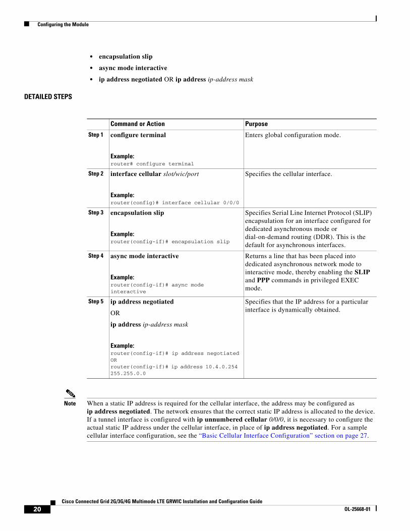
• encapsulation slip
• async mode interactive
• ip address negotiated OR ip address ip-address mask
DETAILED STEPS
Note When a static IP address is required for the cellular interface, the address may be configured as ip address negotiated. The network ensures that the correct static IP address is allocated to the device. If a tunnel interface is configured with ip unnumbered cellular 0/0/0, it is necessary to configure the actual static IP address under the cellular interface, in place of ip address negotiated. For a sample cellular interface configuration, see the “Basic Cellular Interface Configuration” section on page 27.
Command or Action Purpose
Step 1 configure terminal
Example:router# configure terminal
Enters global configuration mode.
Step 2 interface cellular slot/wic/port
Example:router(config)# interface cellular 0/0/0
Specifies the cellular interface.
Step 3 encapsulation slip
Example:router(config-if)# encapsulation slip
Specifies Serial Line Internet Protocol (SLIP) encapsulation for an interface configured for dedicated asynchronous mode or dial-on-demand routing (DDR). This is the default for asynchronous interfaces.
Step 4 async mode interactive
Example:router(config-if)# async mode interactive
Returns a line that has been placed into dedicated asynchronous network mode to interactive mode, thereby enabling the SLIP and PPP commands in privileged EXEC mode.
Step 5 ip address negotiated
OR
ip address ip-address mask
Example:router(config-if)# ip address negotiatedORrouter(config-if)# ip address 10.4.0.254 255.255.0.0
Specifies that the IP address for a particular interface is dynamically obtained.
20Cisco Connected Grid 2G/3G/4G Multimode LTE GRWIC Installation and Configuration Guide
OL-25668-01
Configuring the Module
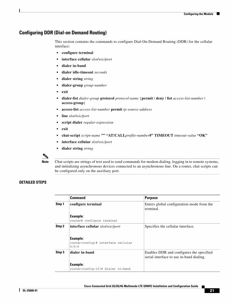
Configuring DDR (Dial-on Demand Routing)
This section contains the commands to configure Dial-On-Demand Routing (DDR) for the cellular interface:
• configure terminal
• interface cellular slot/wic/port
• dialer in-band
• dialer idle-timeout seconds
• dialer string string
• dialer-group group-number
• exit
• dialer-list dialer-group protocol protocol-name {permit | deny | list access-list-number | access-group}
• access-list access-list-number permit ip-source-address
• line slot/wic/port
• script dialer regular-expression
• exit
• chat-script script-name ”” “AT!CALLprofile-number#” TIMEOUT timeout-value “OK”
• interface cellular slot/wic/port
• dialer string string
Note Chat scripts are strings of text used to send commands for modem dialing, logging in to remote systems, and initializing asynchronous devices connected to an asynchronous line. On a router, chat scripts can be configured only on the auxiliary port.
DETAILED STEPS
Command Purpose
Step 1 configure terminal
Example:router# configure terminal
Enters global configuration mode from the terminal.
Step 2 interface cellular slot/wic/port
Example:router(config)# interface cellular 0/0/0
Specifies the cellular interface.
Step 3 dialer in-band
Example:router(config-if)# dialer in-band
Enables DDR and configures the specified serial interface to use in-band dialing.
21Cisco Connected Grid 2G/3G/4G Multimode LTE GRWIC Installation and Configuration Guide
OL-25668-01
Configuring the Module
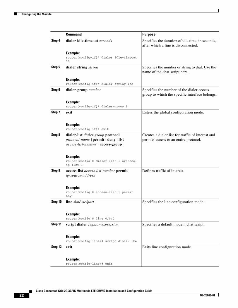
Step 4 dialer idle-timeout seconds
Example:router(config-if)# dialer idle-timeout 30
Specifies the duration of idle time, in seconds, after which a line is disconnected.
Step 5 dialer string string
Example:router(config-if)# dialer string lte
Specifies the number or string to dial. Use the name of the chat script here.
Step 6 dialer-group number
Example:router(config-if)# dialer-group 1
Specifies the number of the dialer access group to which the specific interface belongs.
Step 7 exit
Example:router(config-if)# exit
Enters the global configuration mode.
Step 8 dialer-list dialer-group protocol protocol-name {permit | deny | list access-list-number | access-group}
Example:router(config)# dialer-list 1 protocol ip list 1
Creates a dialer list for traffic of interest and permits access to an entire protocol.
Step 9 access-list access-list-number permit ip-source-address
Example:router(config)# access-list 1 permit any
Defines traffic of interest.
Step 10 line slot/wic/port
Example:router(config)# line 0/0/0
Specifies the line configuration mode.
Step 11 script dialer regular-expression
Example:router(config-line)# script dialer lte
Specifies a default modem chat script.
Step 12 exit
Example:router(config-line)# exit
Exits line configuration mode.
Command Purpose
22Cisco Connected Grid 2G/3G/4G Multimode LTE GRWIC Installation and Configuration Guide
OL-25668-01
Configuring the Module
Configuring DDR Backup
To monitor the primary connection and initiate the backup connection when needed, the router can use one of the following methods:
• Backup Interface—The backup interface stays in standby mode and is brought up when the primary interface line protocol is detected as down.
• Dialer Watch—Dialer watch is a backup feature that integrates dial backup with routing capabilities.
• Floating Static Route—The route through the backup interface is not in the routing table until the primary interface goes down because it has a greater administrative distance than that of the primary connection route.
Configuring Interfaces to Use a Backup Interface
Note You cannot configure a backup interface for the cellular interface and any other asynchronous serial interface.
To configure one or more interfaces to use a backup interface, use the following commands, beginning in global configuration mode.
SUMMARY STEPS
1. interface type number
2. backup interface cellular number
3. backup delay enable-delay-period disable-delay-period
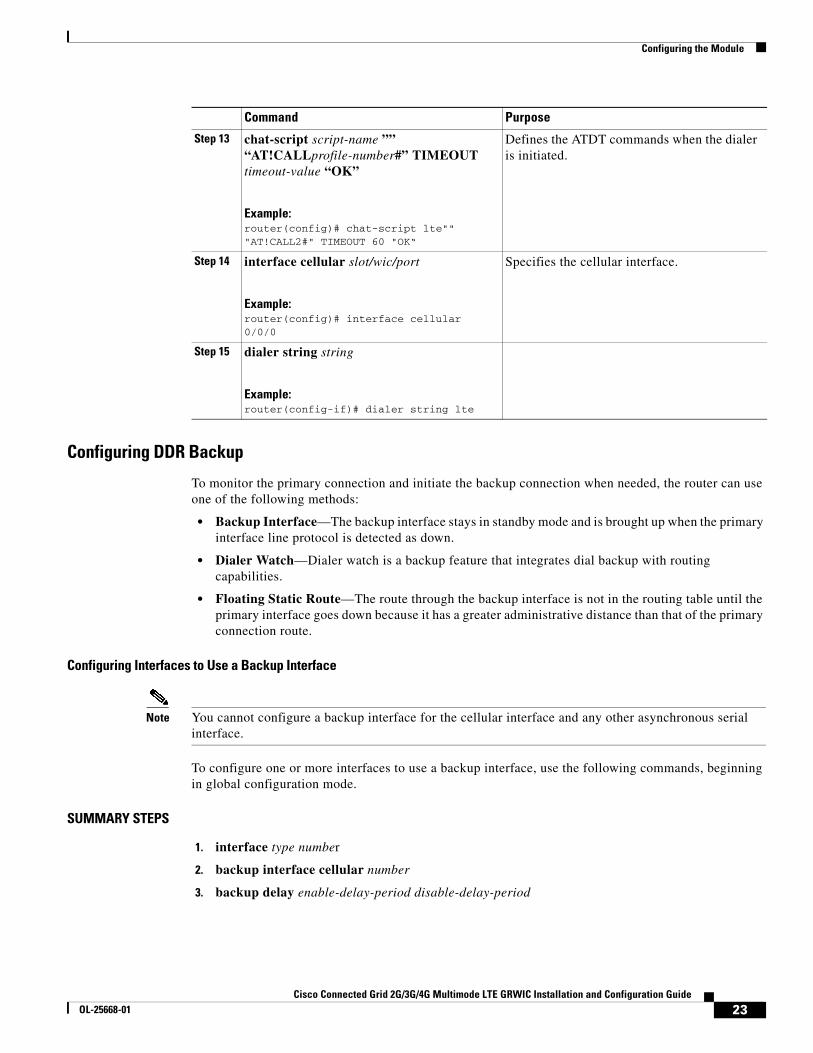
Step 13 chat-script script-name ”” “AT!CALLprofile-number#” TIMEOUT timeout-value “OK”
Example:router(config)# chat-script lte"" "AT!CALL2#" TIMEOUT 60 "OK“
Defines the ATDT commands when the dialer is initiated.
Step 14 interface cellular slot/wic/port
Example:router(config)# interface cellular 0/0/0
Specifies the cellular interface.
Step 15 dialer string string
Example:router(config-if)# dialer string lte
Command Purpose
23Cisco Connected Grid 2G/3G/4G Multimode LTE GRWIC Installation and Configuration Guide
OL-25668-01
Configuring the Module
DETAILED STEPS
Configuring DDR Backup Using Dialer Watch
To initiate dialer watch, you must configure the interface to perform DDR and backup. Use traditional DDR configuration commands, such as dialer maps, for DDR capabilities. To enable dialer watch on the backup interface and create a dialer list, use the following commands in interface configuration mode.
SUMMARY STEPS
1. configure terminal
2. interface type number
3. dialer watch group group-number
4. exit
5. dialer watch-list group-number ip ip-address address-mask
6. dialer-list dialer-group protocol protocol-name {permit | deny | list access-list-number | access-group}
7. ip access-list access-list-number permit ip-source-address
8. interface cellular slot/wic/port
9. dialer string string
Command or Action Purpose
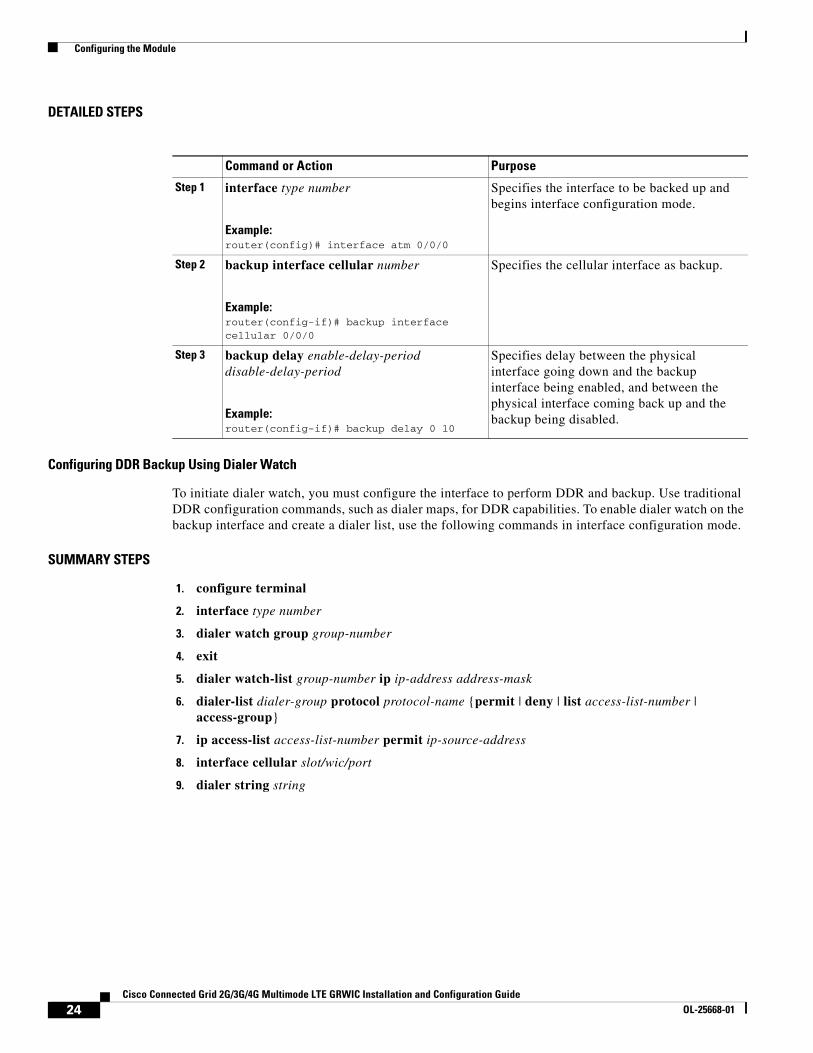
Step 1 interface type number
Example:router(config)# interface atm 0/0/0
Specifies the interface to be backed up and begins interface configuration mode.
Step 2 backup interface cellular number
Example:router(config-if)# backup interface cellular 0/0/0
Specifies the cellular interface as backup.
Step 3 backup delay enable-delay-period disable-delay-period
Example:router(config-if)# backup delay 0 10
Specifies delay between the physical interface going down and the backup interface being enabled, and between the physical interface coming back up and the backup being disabled.
24Cisco Connected Grid 2G/3G/4G Multimode LTE GRWIC Installation and Configuration Guide
OL-25668-01
Configuring the Module
DETAILED STEPS
Command or Action Purpose
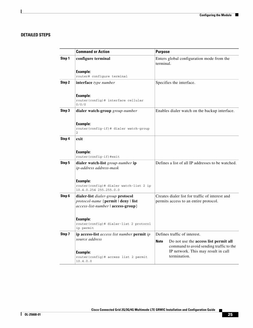
Step 1 configure terminal
Example:router# configure terminal
Enters global configuration mode from the terminal.
Step 2 interface type number
Example:router(config)# interface cellular 0/0/0
Specifies the interface.
Step 3 dialer watch-group group-number
Example:router(config-if)# dialer watch-group 2
Enables dialer watch on the backup interface.
Step 4 exit
Example:router(config-if)#exit
Step 5 dialer watch-list group-number ip ip-address address-mask
Example:router(config)# dialer watch-list 2 ip 10.4.0.254 255.255.0.0
Defines a list of all IP addresses to be watched.
Step 6 dialer-list dialer-group protocol protocol-name {permit | deny | list access-list-number | access-group}
Example:router(config)# dialer-list 2 protocol ip permit
Creates dialer list for traffic of interest and permits access to an entire protocol.
Step 7 ip access-list access list number permit ip source address
Example:router(config)# access list 2 permit 10.4.0.0
Defines traffic of interest.
Note Do not use the access list permit all command to avoid sending traffic to the IP network. This may result in call termination.
25Cisco Connected Grid 2G/3G/4G Multimode LTE GRWIC Installation and Configuration Guide
OL-25668-01
Configuring the Module
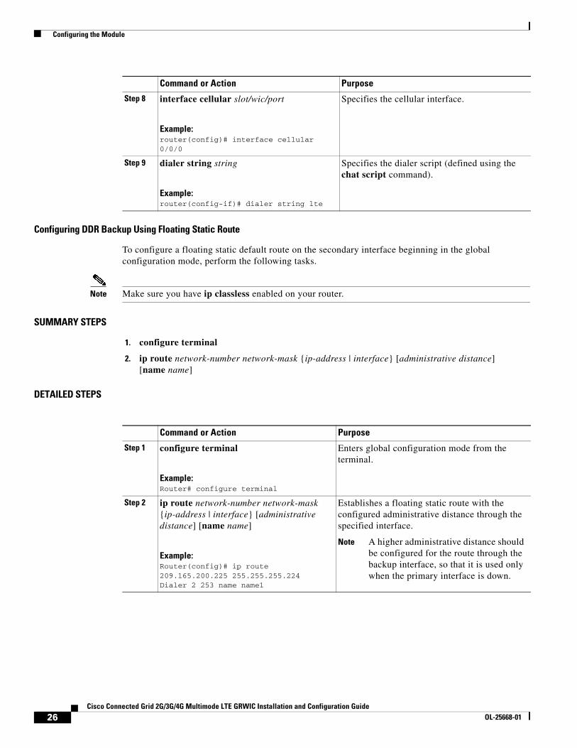
Configuring DDR Backup Using Floating Static Route
To configure a floating static default route on the secondary interface beginning in the global configuration mode, perform the following tasks.
Note Make sure you have ip classless enabled on your router.
SUMMARY STEPS
1. configure terminal
2. ip route network-number network-mask {ip-address | interface} [administrative distance] [name name]
DETAILED STEPS
Step 8 interface cellular slot/wic/port
Example:router(config)# interface cellular 0/0/0
Specifies the cellular interface.
Step 9 dialer string string
Example:router(config-if)# dialer string lte
Specifies the dialer script (defined using the chat script command).
Command or Action Purpose
Command or Action Purpose
Step 1 configure terminal
Example:Router# configure terminal
Enters global configuration mode from the terminal.
Step 2 ip route network-number network-mask {ip-address | interface} [administrative distance] [name name]
Example:Router(config)# ip route 209.165.200.225 255.255.255.224 Dialer 2 253 name name1
Establishes a floating static route with the configured administrative distance through the specified interface.
Note A higher administrative distance should be configured for the route through the backup interface, so that it is used only when the primary interface is down.
26Cisco Connected Grid 2G/3G/4G Multimode LTE GRWIC Installation and Configuration Guide
OL-25668-01
Configuration Examples
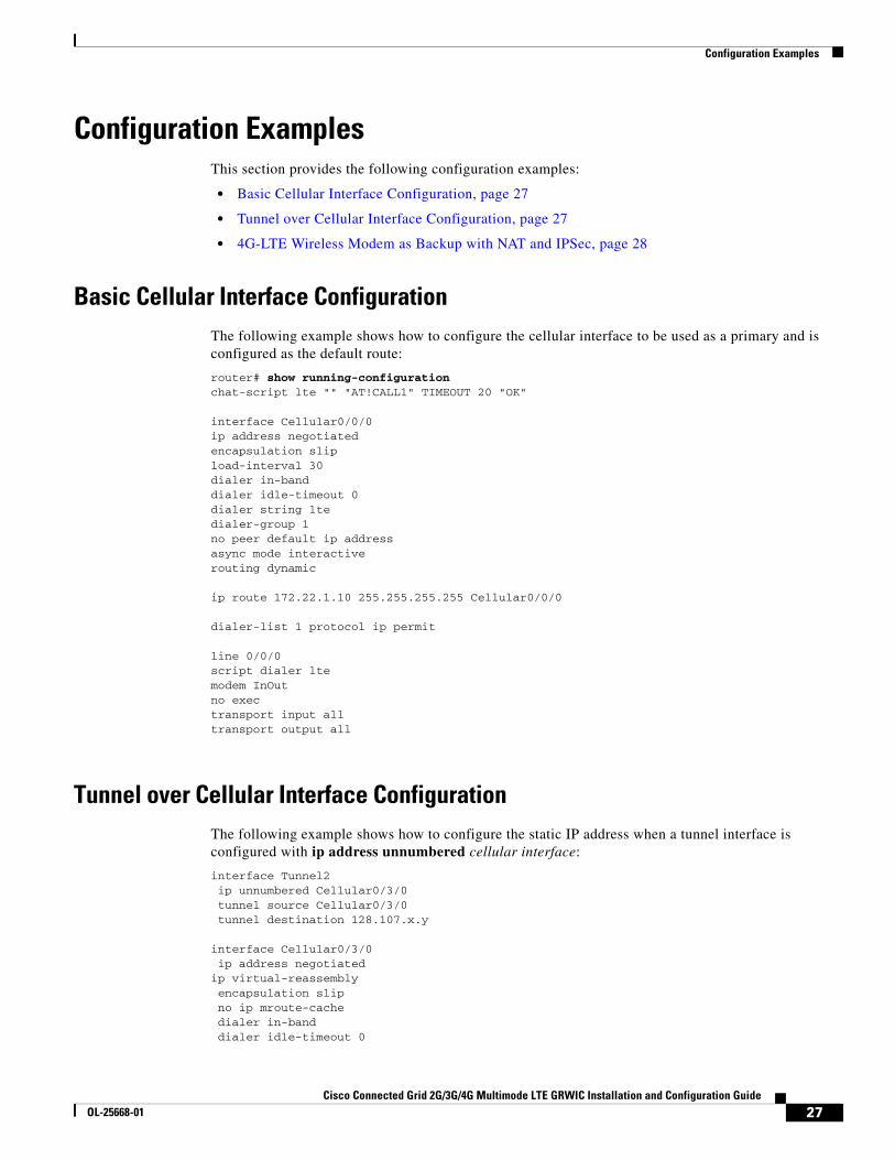
Configuration ExamplesThis section provides the following configuration examples:
• Basic Cellular Interface Configuration, page 27
• Tunnel over Cellular Interface Configuration, page 27
• 4G-LTE Wireless Modem as Backup with NAT and IPSec, page 28
Basic Cellular Interface ConfigurationThe following example shows how to configure the cellular interface to be used as a primary and is configured as the default route:
router# show running-configurationchat-script lte "" "AT!CALL1" TIMEOUT 20 "OK"
interface Cellular0/0/0ip address negotiatedencapsulation slipload-interval 30dialer in-banddialer idle-timeout 0dialer string ltedialer-group 1no peer default ip addressasync mode interactiverouting dynamic
ip route 172.22.1.10 255.255.255.255 Cellular0/0/0
dialer-list 1 protocol ip permit
line 0/0/0script dialer ltemodem InOutno exectransport input alltransport output all
Tunnel over Cellular Interface ConfigurationThe following example shows how to configure the static IP address when a tunnel interface is configured with ip address unnumbered cellular interface:
interface Tunnel2 ip unnumbered Cellular0/3/0 tunnel source Cellular0/3/0 tunnel destination 128.107.x.y
interface Cellular0/3/0 ip address negotiatedip virtual-reassembly encapsulation slip no ip mroute-cache dialer in-band dialer idle-timeout 0
27Cisco Connected Grid 2G/3G/4G Multimode LTE GRWIC Installation and Configuration Guide
OL-25668-01
Configuration Examples
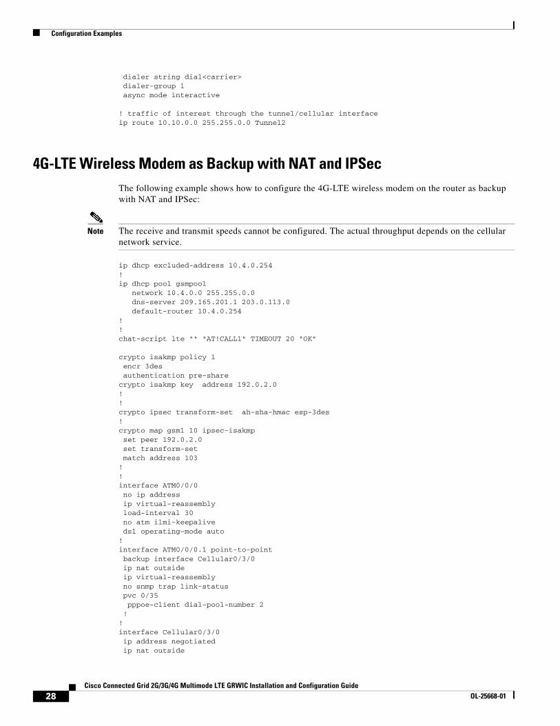
dialer string dial<carrier> dialer-group 1 async mode interactive
! traffic of interest through the tunnel/cellular interfaceip route 10.10.0.0 255.255.0.0 Tunnel2
4G-LTE Wireless Modem as Backup with NAT and IPSecThe following example shows how to configure the 4G-LTE wireless modem on the router as backup with NAT and IPSec:
Note The receive and transmit speeds cannot be configured. The actual throughput depends on the cellular network service.
ip dhcp excluded-address 10.4.0.254!ip dhcp pool gsmpool network 10.4.0.0 255.255.0.0 dns-server 209.165.201.1 203.0.113.0 default-router 10.4.0.254 !!chat-script lte "" "AT!CALL1" TIMEOUT 20 "OK"
crypto isakmp policy 1 encr 3des authentication pre-sharecrypto isakmp key address 192.0.2.0!!crypto ipsec transform-set ah-sha-hmac esp-3des !crypto map gsm1 10 ipsec-isakmp set peer 192.0.2.0 set transform-set match address 103!!interface ATM0/0/0 no ip address ip virtual-reassembly load-interval 30 no atm ilmi-keepalive dsl operating-mode auto !interface ATM0/0/0.1 point-to-point backup interface Cellular0/3/0 ip nat outside ip virtual-reassembly no snmp trap link-status pvc 0/35 pppoe-client dial-pool-number 2 !!interface Cellular0/3/0 ip address negotiated ip nat outside
28Cisco Connected Grid 2G/3G/4G Multimode LTE GRWIC Installation and Configuration Guide
OL-25668-01
Configuration Examples
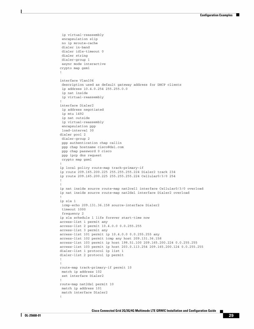
ip virtual-reassembly encapsulation slip no ip mroute-cache dialer in-band dialer idle-timeout 0 dialer string dialer-group 1 async mode interactivecrypto map gsm1!
interface Vlan104 description used as default gateway address for DHCP clients ip address 10.4.0.254 255.255.0.0 ip nat inside ip virtual-reassembly!interface Dialer2 ip address negotiated ip mtu 1492 ip nat outside ip virtual-reassembly encapsulation ppp load-interval 30dialer pool 2 dialer-group 2 ppp authentication chap callin ppp chap hostname [email protected] ppp chap password 0 cisco ppp ipcp dns request crypto map gsm1!ip local policy route-map track-primary-ifip route 209.165.200.225 255.255.255.224 Dialer2 track 234ip route 209.165.200.225 255.255.255.224 Cellular0/3/0 254!!ip nat inside source route-map nat2cell interface Cellular0/3/0 overloadip nat inside source route-map nat2dsl interface Dialer2 overload!ip sla 1 icmp-echo 209.131.36.158 source-interface Dialer2 timeout 1000 frequency 2ip sla schedule 1 life forever start-time nowaccess-list 1 permit anyaccess-list 2 permit 10.4.0.0 0.0.255.255access-list 3 permit anyaccess-list 101 permit ip 10.4.0.0 0.0.255.255 anyaccess-list 102 permit icmp any host 209.131.36.158access-list 103 permit ip host 198.51.100 209.165.200.224 0.0.255.255access-list 103 permit ip host 203.0.113.254 209.165.200.124 0.0.255.255dialer-list 1 protocol ip list 1dialer-list 2 protocol ip permit!!route-map track-primary-if permit 10 match ip address 102 set interface Dialer2!route-map nat2dsl permit 10 match ip address 101 match interface Dialer2!
29Cisco Connected Grid 2G/3G/4G Multimode LTE GRWIC Installation and Configuration Guide
OL-25668-01
SNMP MIBs
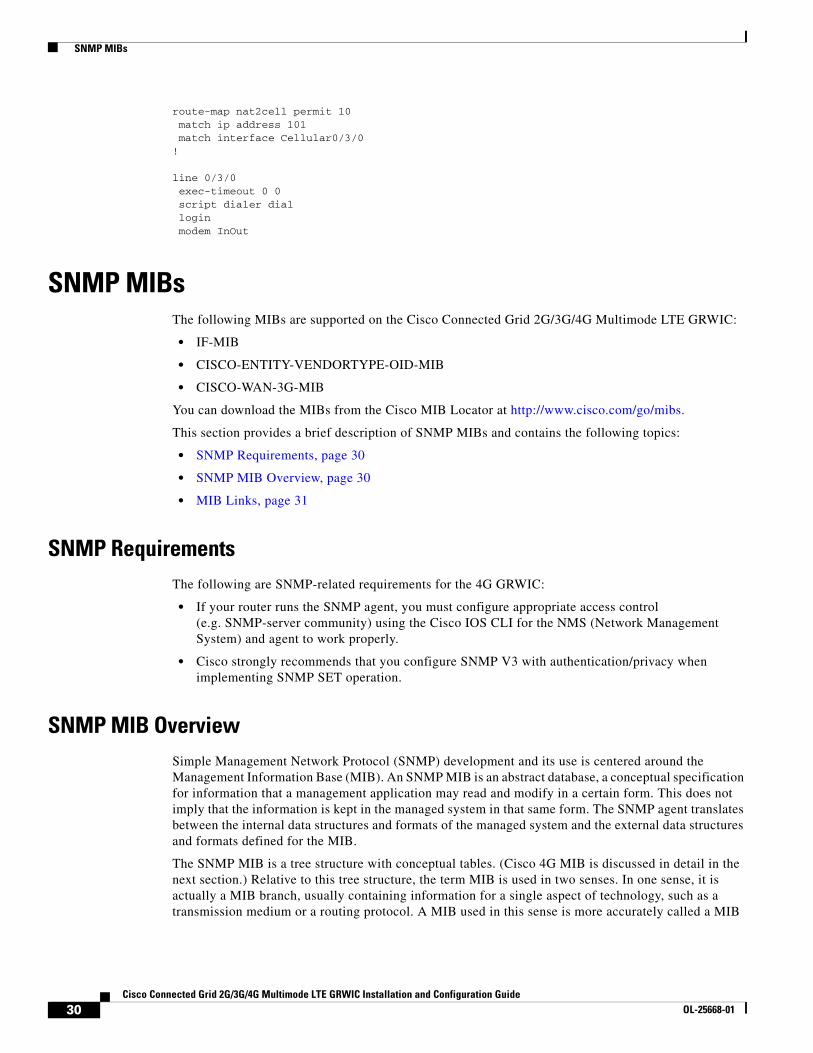
route-map nat2cell permit 10 match ip address 101 match interface Cellular0/3/0!
line 0/3/0 exec-timeout 0 0 script dialer dial login modem InOut
SNMP MIBsThe following MIBs are supported on the Cisco Connected Grid 2G/3G/4G Multimode LTE GRWIC:
• IF-MIB
• CISCO-ENTITY-VENDORTYPE-OID-MIB
• CISCO-WAN-3G-MIB
You can download the MIBs from the Cisco MIB Locator at http://www.cisco.com/go/mibs.
This section provides a brief description of SNMP MIBs and contains the following topics:
• SNMP Requirements, page 30
• SNMP MIB Overview, page 30
• MIB Links, page 31
SNMP RequirementsThe following are SNMP-related requirements for the 4G GRWIC:
• If your router runs the SNMP agent, you must configure appropriate access control (e.g. SNMP-server community) using the Cisco IOS CLI for the NMS (Network Management System) and agent to work properly.
• Cisco strongly recommends that you configure SNMP V3 with authentication/privacy when implementing SNMP SET operation.
SNMP MIB OverviewSimple Management Network Protocol (SNMP) development and its use is centered around the Management Information Base (MIB). An SNMP MIB is an abstract database, a conceptual specification for information that a management application may read and modify in a certain form. This does not imply that the information is kept in the managed system in that same form. The SNMP agent translates between the internal data structures and formats of the managed system and the external data structures and formats defined for the MIB.
The SNMP MIB is a tree structure with conceptual tables. (Cisco 4G MIB is discussed in detail in the next section.) Relative to this tree structure, the term MIB is used in two senses. In one sense, it is actually a MIB branch, usually containing information for a single aspect of technology, such as a transmission medium or a routing protocol. A MIB used in this sense is more accurately called a MIB
30Cisco Connected Grid 2G/3G/4G Multimode LTE GRWIC Installation and Configuration Guide
OL-25668-01
Troubleshooting and Diagnostics
module, and is usually defined in a single document. In the other sense, a MIB is a collection of such branches. Such a collection might comprise, for example, all the MIB modules implemented by a given agent, or the entire collection of MIB modules defined for SNMP.
A MIB is a tree where the leaves are individual items of data called objects. An object may be, for example, a counter or a protocol status. MIB objects are also sometimes called variables.
MIBs can be classified into three categories:
• IF MIBs—Describes interface statistics
• Cisco-Entity-Vendortype-OID-MIB.my—ENTITY-MIBs are used to provide general hardware type for both the HWIC and the modem. CISCO-ENTITY-VENDORTYPE-OID-MIB assigns OIDs for Cisco components (including the HWICs & the modems). The OIDs are then used as the values of entPhysicalVendorType in the ENTITY-MIB.
• 3G/Wireless MIBs—Cellular or wireless-specific MIBs
MIB LinksTo locate and download the following MIBs for selected platforms, Cisco software releases, and feature sets, search the MIB name in Cisco MIB Locator found at: http://www.cisco.com/go/mibs
• IF-MIB
• CISCO-ENTITY-VENDORTYPE-OID-MIB
• CISCO-WAN-3G-MIB
Troubleshooting and DiagnosticsThis section provides the necessary background information and resources available for troubleshooting the Cisco Cisco Connected Grid 2G/3G/4G Multimode LTE GRWIC.
For LED descriptions, see Ports and LEDs, page 7.
• Verifying Data Call Setup, page 32
• Checking Signal Strength, page 32
• Verifying Service Availability, page 32
• Successful Call Setup, page 34
• Modem Troubleshooting, page 35
• Modem Settings, page 36
• Retrieving the Electronic Serial Number (ESN), page 38
• Converting Hexadecimal ESN to Decimal Notation, page 38
31Cisco Connected Grid 2G/3G/4G Multimode LTE GRWIC Installation and Configuration Guide
OL-25668-01
Troubleshooting and Diagnostics
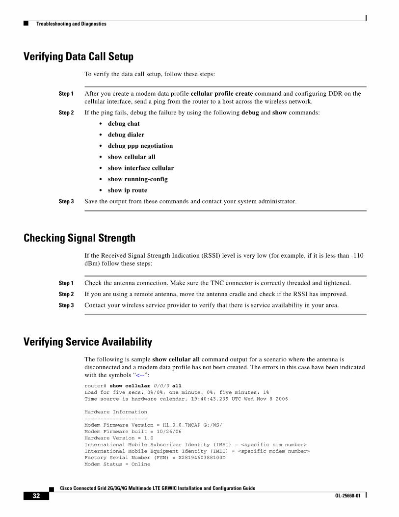
Verifying Data Call Setup To verify the data call setup, follow these steps:
Step 1 After you create a modem data profile cellular profile create command and configuring DDR on the cellular interface, send a ping from the router to a host across the wireless network.
Step 2 If the ping fails, debug the failure by using the following debug and show commands:
• debug chat
• debug dialer
• debug ppp negotiation
• show cellular all
• show interface cellular
• show running-config
• show ip route
Step 3 Save the output from these commands and contact your system administrator.
Checking Signal StrengthIf the Received Signal Strength Indication (RSSI) level is very low (for example, if it is less than -110 dBm) follow these steps:
Step 1 Check the antenna connection. Make sure the TNC connector is correctly threaded and tightened.
Step 2 If you are using a remote antenna, move the antenna cradle and check if the RSSI has improved.
Step 3 Contact your wireless service provider to verify that there is service availability in your area.
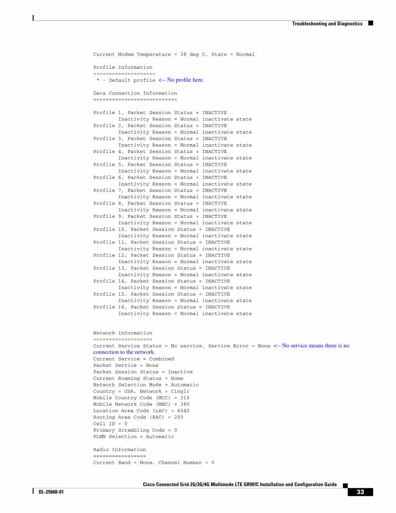
Verifying Service AvailabilityThe following is sample show cellular all command output for a scenario where the antenna is disconnected and a modem data profile has not been created. The errors in this case have been indicated with the symbols “<--”:
router# show cellular 0/0/0 allLoad for five secs: 0%/0%; one minute: 0%; five minutes: 1%Time source is hardware calendar, 19:40:43.239 UTC Wed Nov 8 2006
Hardware Information====================Modem Firmware Version = H1_0_0_7MCAP G:/WS/Modem Firmware built = 10/26/06Hardware Version = 1.0International Mobile Subscriber Identity (IMSI) = <specific sim number>International Mobile Equipment Identity (IMEI) = <specific modem number>Factory Serial Number (FSN) = X2819460388100DModem Status = Online
32Cisco Connected Grid 2G/3G/4G Multimode LTE GRWIC Installation and Configuration Guide
OL-25668-01
Troubleshooting and Diagnostics
Current Modem Temperature = 38 deg C, State = Normal
Profile Information==================== * - Default profile <-- No profile here.
Data Connection Information===========================
Profile 1, Packet Session Status = INACTIVE Inactivity Reason = Normal inactivate stateProfile 2, Packet Session Status = INACTIVE Inactivity Reason = Normal inactivate stateProfile 3, Packet Session Status = INACTIVE Inactivity Reason = Normal inactivate stateProfile 4, Packet Session Status = INACTIVE Inactivity Reason = Normal inactivate stateProfile 5, Packet Session Status = INACTIVE Inactivity Reason = Normal inactivate stateProfile 6, Packet Session Status = INACTIVE Inactivity Reason = Normal inactivate stateProfile 7, Packet Session Status = INACTIVE Inactivity Reason = Normal inactivate stateProfile 8, Packet Session Status = INACTIVE Inactivity Reason = Normal inactivate stateProfile 9, Packet Session Status = INACTIVE Inactivity Reason = Normal inactivate stateProfile 10, Packet Session Status = INACTIVE Inactivity Reason = Normal inactivate stateProfile 11, Packet Session Status = INACTIVE Inactivity Reason = Normal inactivate stateProfile 12, Packet Session Status = INACTIVE Inactivity Reason = Normal inactivate stateProfile 13, Packet Session Status = INACTIVE Inactivity Reason = Normal inactivate stateProfile 14, Packet Session Status = INACTIVE Inactivity Reason = Normal inactivate stateProfile 15, Packet Session Status = INACTIVE Inactivity Reason = Normal inactivate stateProfile 16, Packet Session Status = INACTIVE Inactivity Reason = Normal inactivate state
Network Information===================Current Service Status = No service, Service Error = None <-- No service means there is no connection to the network.Current Service = CombinedPacket Service = NonePacket Session Status = InactiveCurrent Roaming Status = HomeNetwork Selection Mode = AutomaticCountry = USA, Network = CinglrMobile Country Code (MCC) = 310Mobile Network Code (MNC) = 380Location Area Code (LAC) = 6042Routing Area Code (RAC) = 255Cell ID = 0Primary Scrambling Code = 0PLMN Selection = Automatic
Radio Information=================Current Band = None, Channel Number = 0
33Cisco Connected Grid 2G/3G/4G Multimode LTE GRWIC Installation and Configuration Guide
OL-25668-01
Troubleshooting and Diagnostics
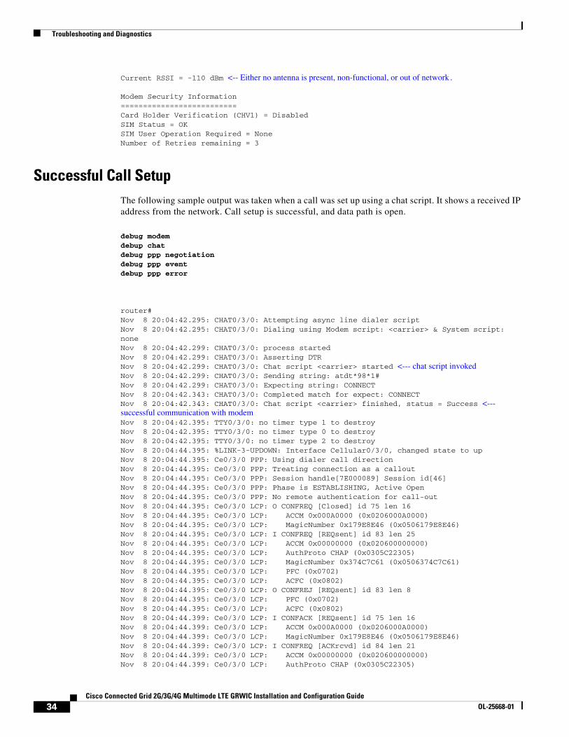
Current RSSI = -110 dBm <-- Either no antenna is present, non-functional, or out of network.
Modem Security Information==========================Card Holder Verification (CHV1) = DisabledSIM Status = OKSIM User Operation Required = NoneNumber of Retries remaining = 3
Successful Call SetupThe following sample output was taken when a call was set up using a chat script. It shows a received IP address from the network. Call setup is successful, and data path is open.
debug modemdebup chatdebug ppp negotiationdebug ppp eventdebup ppp error
router#Nov 8 20:04:42.295: CHAT0/3/0: Attempting async line dialer scriptNov 8 20:04:42.295: CHAT0/3/0: Dialing using Modem script: <carrier> & System script: noneNov 8 20:04:42.299: CHAT0/3/0: process startedNov 8 20:04:42.299: CHAT0/3/0: Asserting DTRNov 8 20:04:42.299: CHAT0/3/0: Chat script <carrier> started <--- chat script invokedNov 8 20:04:42.299: CHAT0/3/0: Sending string: atdt*98*1# Nov 8 20:04:42.299: CHAT0/3/0: Expecting string: CONNECT Nov 8 20:04:42.343: CHAT0/3/0: Completed match for expect: CONNECTNov 8 20:04:42.343: CHAT0/3/0: Chat script <carrier> finished, status = Success <--- successful communication with modemNov 8 20:04:42.395: TTY0/3/0: no timer type 1 to destroyNov 8 20:04:42.395: TTY0/3/0: no timer type 0 to destroyNov 8 20:04:42.395: TTY0/3/0: no timer type 2 to destroyNov 8 20:04:44.395: %LINK-3-UPDOWN: Interface Cellular0/3/0, changed state to upNov 8 20:04:44.395: Ce0/3/0 PPP: Using dialer call directionNov 8 20:04:44.395: Ce0/3/0 PPP: Treating connection as a calloutNov 8 20:04:44.395: Ce0/3/0 PPP: Session handle[7E000089] Session id[46]Nov 8 20:04:44.395: Ce0/3/0 PPP: Phase is ESTABLISHING, Active OpenNov 8 20:04:44.395: Ce0/3/0 PPP: No remote authentication for call-outNov 8 20:04:44.395: Ce0/3/0 LCP: O CONFREQ [Closed] id 75 len 16Nov 8 20:04:44.395: Ce0/3/0 LCP: ACCM 0x000A0000 (0x0206000A0000)Nov 8 20:04:44.395: Ce0/3/0 LCP: MagicNumber 0x179E8E46 (0x0506179E8E46)Nov 8 20:04:44.395: Ce0/3/0 LCP: I CONFREQ [REQsent] id 83 len 25Nov 8 20:04:44.395: Ce0/3/0 LCP: ACCM 0x00000000 (0x020600000000)Nov 8 20:04:44.395: Ce0/3/0 LCP: AuthProto CHAP (0x0305C22305)Nov 8 20:04:44.395: Ce0/3/0 LCP: MagicNumber 0x374C7C61 (0x0506374C7C61)Nov 8 20:04:44.395: Ce0/3/0 LCP: PFC (0x0702)Nov 8 20:04:44.395: Ce0/3/0 LCP: ACFC (0x0802)Nov 8 20:04:44.395: Ce0/3/0 LCP: O CONFREJ [REQsent] id 83 len 8Nov 8 20:04:44.395: Ce0/3/0 LCP: PFC (0x0702)Nov 8 20:04:44.395: Ce0/3/0 LCP: ACFC (0x0802)Nov 8 20:04:44.399: Ce0/3/0 LCP: I CONFACK [REQsent] id 75 len 16Nov 8 20:04:44.399: Ce0/3/0 LCP: ACCM 0x000A0000 (0x0206000A0000)Nov 8 20:04:44.399: Ce0/3/0 LCP: MagicNumber 0x179E8E46 (0x0506179E8E46)Nov 8 20:04:44.399: Ce0/3/0 LCP: I CONFREQ [ACKrcvd] id 84 len 21Nov 8 20:04:44.399: Ce0/3/0 LCP: ACCM 0x00000000 (0x020600000000)Nov 8 20:04:44.399: Ce0/3/0 LCP: AuthProto CHAP (0x0305C22305)
34Cisco Connected Grid 2G/3G/4G Multimode LTE GRWIC Installation and Configuration Guide
OL-25668-01
Troubleshooting and Diagnostics
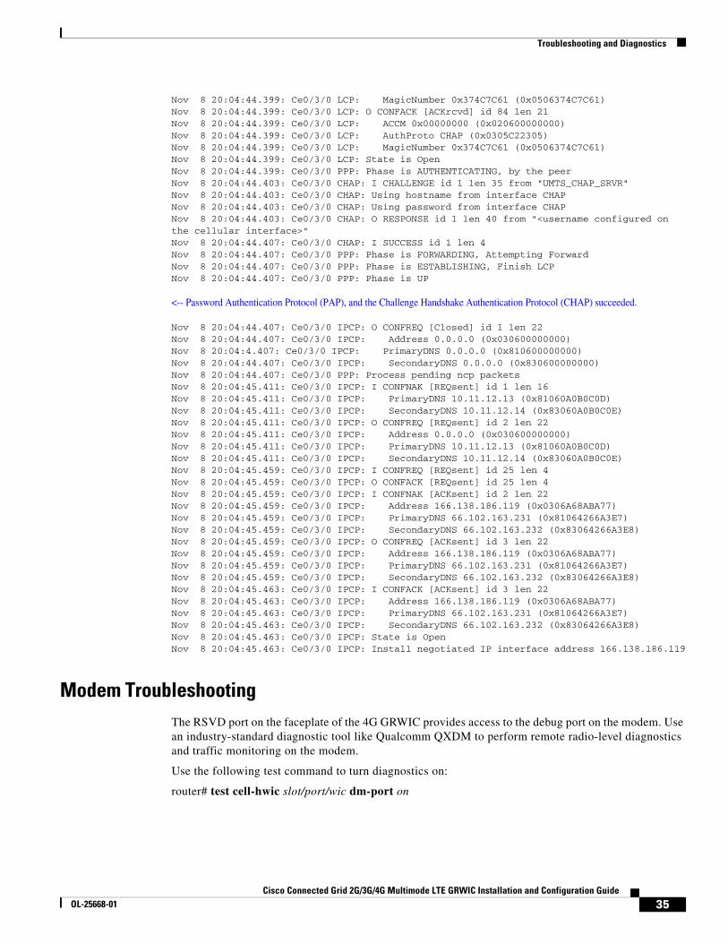
Nov 8 20:04:44.399: Ce0/3/0 LCP: MagicNumber 0x374C7C61 (0x0506374C7C61)Nov 8 20:04:44.399: Ce0/3/0 LCP: O CONFACK [ACKrcvd] id 84 len 21Nov 8 20:04:44.399: Ce0/3/0 LCP: ACCM 0x00000000 (0x020600000000)Nov 8 20:04:44.399: Ce0/3/0 LCP: AuthProto CHAP (0x0305C22305)Nov 8 20:04:44.399: Ce0/3/0 LCP: MagicNumber 0x374C7C61 (0x0506374C7C61)Nov 8 20:04:44.399: Ce0/3/0 LCP: State is OpenNov 8 20:04:44.399: Ce0/3/0 PPP: Phase is AUTHENTICATING, by the peerNov 8 20:04:44.403: Ce0/3/0 CHAP: I CHALLENGE id 1 len 35 from "UMTS_CHAP_SRVR"Nov 8 20:04:44.403: Ce0/3/0 CHAP: Using hostname from interface CHAPNov 8 20:04:44.403: Ce0/3/0 CHAP: Using password from interface CHAPNov 8 20:04:44.403: Ce0/3/0 CHAP: O RESPONSE id 1 len 40 from "<username configured on the cellular interface>" Nov 8 20:04:44.407: Ce0/3/0 CHAP: I SUCCESS id 1 len 4Nov 8 20:04:44.407: Ce0/3/0 PPP: Phase is FORWARDING, Attempting ForwardNov 8 20:04:44.407: Ce0/3/0 PPP: Phase is ESTABLISHING, Finish LCPNov 8 20:04:44.407: Ce0/3/0 PPP: Phase is UP
<-- Password Authentication Protocol (PAP), and the Challenge Handshake Authentication Protocol (CHAP) succeeded.
Nov 8 20:04:44.407: Ce0/3/0 IPCP: O CONFREQ [Closed] id 1 len 22Nov 8 20:04:44.407: Ce0/3/0 IPCP: Address 0.0.0.0 (0x030600000000)Nov 8 20:04:4.407: Ce0/3/0 IPCP: PrimaryDNS 0.0.0.0 (0x810600000000)Nov 8 20:04:44.407: Ce0/3/0 IPCP: SecondaryDNS 0.0.0.0 (0x830600000000)Nov 8 20:04:44.407: Ce0/3/0 PPP: Process pending ncp packetsNov 8 20:04:45.411: Ce0/3/0 IPCP: I CONFNAK [REQsent] id 1 len 16Nov 8 20:04:45.411: Ce0/3/0 IPCP: PrimaryDNS 10.11.12.13 (0x81060A0B0C0D)Nov 8 20:04:45.411: Ce0/3/0 IPCP: SecondaryDNS 10.11.12.14 (0x83060A0B0C0E)Nov 8 20:04:45.411: Ce0/3/0 IPCP: O CONFREQ [REQsent] id 2 len 22Nov 8 20:04:45.411: Ce0/3/0 IPCP: Address 0.0.0.0 (0x030600000000)Nov 8 20:04:45.411: Ce0/3/0 IPCP: PrimaryDNS 10.11.12.13 (0x81060A0B0C0D)Nov 8 20:04:45.411: Ce0/3/0 IPCP: SecondaryDNS 10.11.12.14 (0x83060A0B0C0E)Nov 8 20:04:45.459: Ce0/3/0 IPCP: I CONFREQ [REQsent] id 25 len 4Nov 8 20:04:45.459: Ce0/3/0 IPCP: O CONFACK [REQsent] id 25 len 4Nov 8 20:04:45.459: Ce0/3/0 IPCP: I CONFNAK [ACKsent] id 2 len 22Nov 8 20:04:45.459: Ce0/3/0 IPCP: Address 166.138.186.119 (0x0306A68ABA77)Nov 8 20:04:45.459: Ce0/3/0 IPCP: PrimaryDNS 66.102.163.231 (0x81064266A3E7)Nov 8 20:04:45.459: Ce0/3/0 IPCP: SecondaryDNS 66.102.163.232 (0x83064266A3E8)Nov 8 20:04:45.459: Ce0/3/0 IPCP: O CONFREQ [ACKsent] id 3 len 22Nov 8 20:04:45.459: Ce0/3/0 IPCP: Address 166.138.186.119 (0x0306A68ABA77)Nov 8 20:04:45.459: Ce0/3/0 IPCP: PrimaryDNS 66.102.163.231 (0x81064266A3E7)Nov 8 20:04:45.459: Ce0/3/0 IPCP: SecondaryDNS 66.102.163.232 (0x83064266A3E8)Nov 8 20:04:45.463: Ce0/3/0 IPCP: I CONFACK [ACKsent] id 3 len 22Nov 8 20:04:45.463: Ce0/3/0 IPCP: Address 166.138.186.119 (0x0306A68ABA77)Nov 8 20:04:45.463: Ce0/3/0 IPCP: PrimaryDNS 66.102.163.231 (0x81064266A3E7)Nov 8 20:04:45.463: Ce0/3/0 IPCP: SecondaryDNS 66.102.163.232 (0x83064266A3E8)Nov 8 20:04:45.463: Ce0/3/0 IPCP: State is OpenNov 8 20:04:45.463: Ce0/3/0 IPCP: Install negotiated IP interface address 166.138.186.119
Modem TroubleshootingThe RSVD port on the faceplate of the 4G GRWIC provides access to the debug port on the modem. Use an industry-standard diagnostic tool like Qualcomm QXDM to perform remote radio-level diagnostics and traffic monitoring on the modem.
Use the following test command to turn diagnostics on:
router# test cell-hwic slot/port/wic dm-port on
35Cisco Connected Grid 2G/3G/4G Multimode LTE GRWIC Installation and Configuration Guide
OL-25668-01
Troubleshooting and Diagnostics
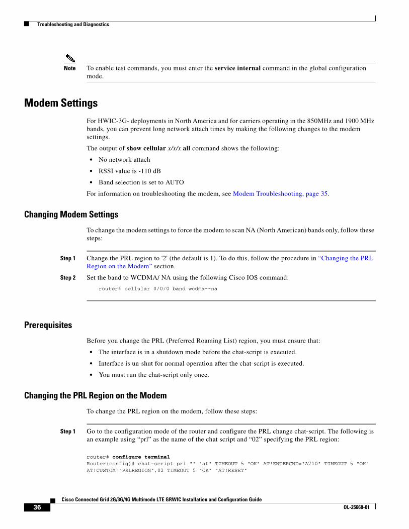
Note To enable test commands, you must enter the service internal command in the global configuration mode.
Modem SettingsFor HWIC-3G- deployments in North America and for carriers operating in the 850MHz and 1900 MHz bands, you can prevent long network attach times by making the following changes to the modem settings.
The output of show cellular x/x/x all command shows the following:
• No network attach
• RSSI value is -110 dB
• Band selection is set to AUTO
For information on troubleshooting the modem, see Modem Troubleshooting, page 35.
Changing Modem Settings
To change the modem settings to force the modem to scan NA (North American) bands only, follow these steps:
Step 1 Change the PRL region to '2' (the default is 1). To do this, follow the procedure in “Changing the PRL Region on the Modem” section.
Step 2 Set the band to WCDMA/ NA using the following Cisco IOS command:
router# cellular 0/0/0 band wcdma--na
Prerequisites
Before you change the PRL (Preferred Roaming List) region, you must ensure that:
• The interface is in a shutdown mode before the chat-script is executed.
• Interface is un-shut for normal operation after the chat-script is executed.
• You must run the chat-script only once.
Changing the PRL Region on the Modem
To change the PRL region on the modem, follow these steps:
Step 1 Go to the configuration mode of the router and configure the PRL change chat-script. The following is an example using “prl” as the name of the chat script and “02” specifying the PRL region:
router# configure terminalRouter(config)# chat-script prl "" "at" TIMEOUT 5 "OK" AT!ENTERCND="A710" TIMEOUT 5 "OK" AT!CUSTOM="PRLREGION",02 TIMEOUT 5 "OK" "AT!RESET"
36Cisco Connected Grid 2G/3G/4G Multimode LTE GRWIC Installation and Configuration Guide
OL-25668-01
Troubleshooting and Diagnostics
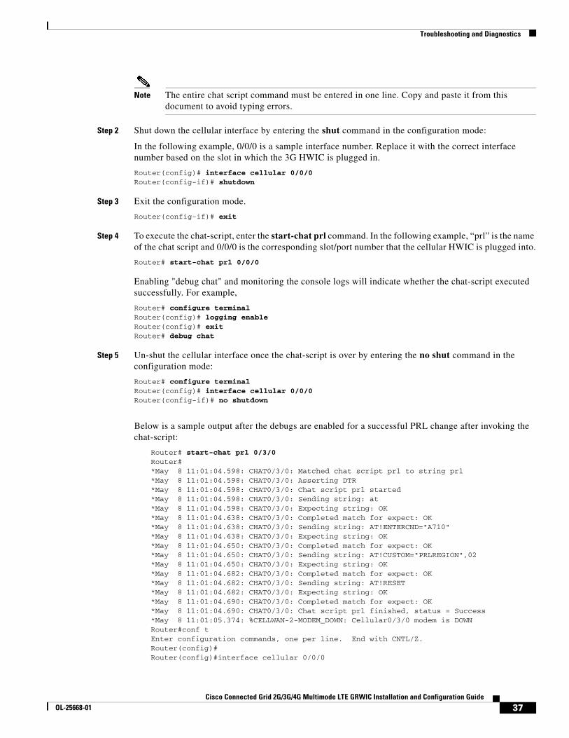
Note The entire chat script command must be entered in one line. Copy and paste it from this document to avoid typing errors.
Step 2 Shut down the cellular interface by entering the shut command in the configuration mode:
In the following example, 0/0/0 is a sample interface number. Replace it with the correct interface number based on the slot in which the 3G HWIC is plugged in.
Router(config)# interface cellular 0/0/0Router(config-if)# shutdown
Step 3 Exit the configuration mode.
Router(config-if)# exit
Step 4 To execute the chat-script, enter the start-chat prl command. In the following example, “prl” is the name of the chat script and 0/0/0 is the corresponding slot/port number that the cellular HWIC is plugged into.
Router# start-chat prl 0/0/0
Enabling "debug chat" and monitoring the console logs will indicate whether the chat-script executed successfully. For example,
Router# configure terminalRouter(config)# logging enableRouter(config)# exitRouter# debug chat
Step 5 Un-shut the cellular interface once the chat-script is over by entering the no shut command in the configuration mode:
Router# configure terminalRouter(config)# interface cellular 0/0/0Router(config-if)# no shutdown
Below is a sample output after the debugs are enabled for a successful PRL change after invoking the chat-script:
Router# start-chat prl 0/3/0Router#*May 8 11:01:04.598: CHAT0/3/0: Matched chat script prl to string prl*May 8 11:01:04.598: CHAT0/3/0: Asserting DTR*May 8 11:01:04.598: CHAT0/3/0: Chat script prl started*May 8 11:01:04.598: CHAT0/3/0: Sending string: at*May 8 11:01:04.598: CHAT0/3/0: Expecting string: OK*May 8 11:01:04.638: CHAT0/3/0: Completed match for expect: OK*May 8 11:01:04.638: CHAT0/3/0: Sending string: AT!ENTERCND="A710"*May 8 11:01:04.638: CHAT0/3/0: Expecting string: OK*May 8 11:01:04.650: CHAT0/3/0: Completed match for expect: OK*May 8 11:01:04.650: CHAT0/3/0: Sending string: AT!CUSTOM="PRLREGION",02*May 8 11:01:04.650: CHAT0/3/0: Expecting string: OK*May 8 11:01:04.682: CHAT0/3/0: Completed match for expect: OK*May 8 11:01:04.682: CHAT0/3/0: Sending string: AT!RESET*May 8 11:01:04.682: CHAT0/3/0: Expecting string: OK*May 8 11:01:04.690: CHAT0/3/0: Completed match for expect: OK*May 8 11:01:04.690: CHAT0/3/0: Chat script prl finished, status = Success*May 8 11:01:05.374: %CELLWAN-2-MODEM_DOWN: Cellular0/3/0 modem is DOWNRouter#conf tEnter configuration commands, one per line. End with CNTL/Z.Router(config)#Router(config)#interface cellular 0/0/0
37Cisco Connected Grid 2G/3G/4G Multimode LTE GRWIC Installation and Configuration Guide
OL-25668-01
Troubleshooting and Diagnostics
Router(config-if)#no shut*May 9 01:48:58.398: %LINK-5-CHANGED: Interface Cellular0/0/0, changed state to upRouter(config-if)#exitRouter(config)#exitRouter#
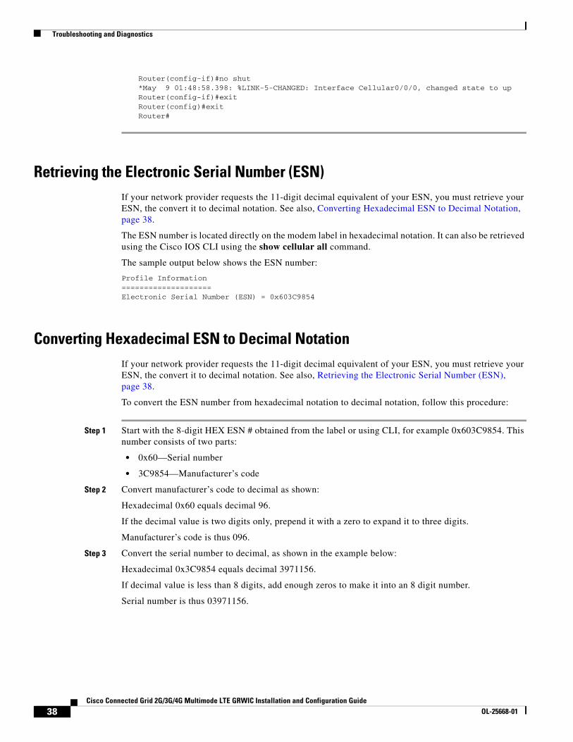
Retrieving the Electronic Serial Number (ESN)If your network provider requests the 11-digit decimal equivalent of your ESN, you must retrieve your ESN, the convert it to decimal notation. See also, Converting Hexadecimal ESN to Decimal Notation, page 38.
The ESN number is located directly on the modem label in hexadecimal notation. It can also be retrieved using the Cisco IOS CLI using the show cellular all command.
The sample output below shows the ESN number:
Profile Information====================Electronic Serial Number (ESN) = 0x603C9854
Converting Hexadecimal ESN to Decimal NotationIf your network provider requests the 11-digit decimal equivalent of your ESN, you must retrieve your ESN, the convert it to decimal notation. See also, Retrieving the Electronic Serial Number (ESN), page 38.
To convert the ESN number from hexadecimal notation to decimal notation, follow this procedure:
Step 1 Start with the 8-digit HEX ESN # obtained from the label or using CLI, for example 0x603C9854. This number consists of two parts:
• 0x60—Serial number
• 3C9854—Manufacturer’s code
Step 2 Convert manufacturer’s code to decimal as shown:
Hexadecimal 0x60 equals decimal 96.
If the decimal value is two digits only, prepend it with a zero to expand it to three digits.
Manufacturer’s code is thus 096.
Step 3 Convert the serial number to decimal, as shown in the example below:
Hexadecimal 0x3C9854 equals decimal 3971156.
If decimal value is less than 8 digits, add enough zeros to make it into an 8 digit number.
Serial number is thus 03971156.
38Cisco Connected Grid 2G/3G/4G Multimode LTE GRWIC Installation and Configuration Guide
OL-25668-01
Additional References
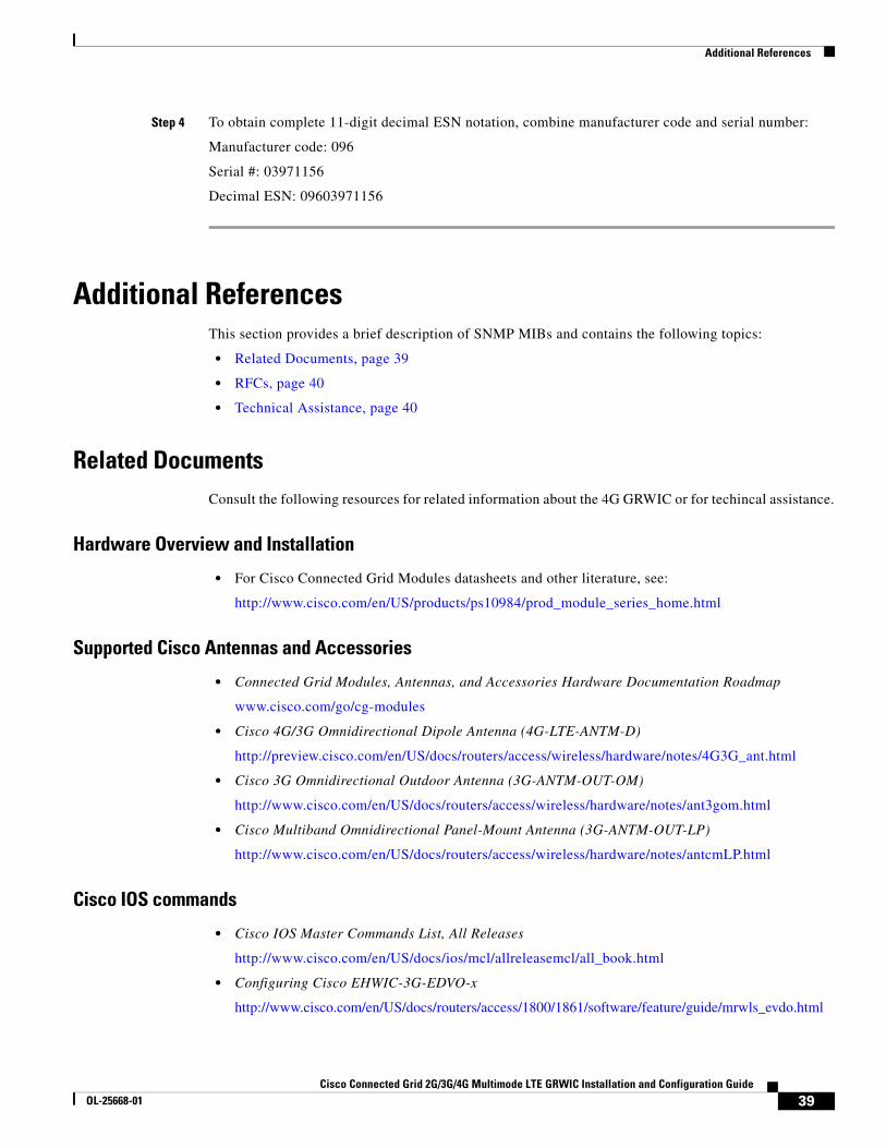
Step 4 To obtain complete 11-digit decimal ESN notation, combine manufacturer code and serial number:
Manufacturer code: 096
Serial #: 03971156
Decimal ESN: 09603971156
Additional ReferencesThis section provides a brief description of SNMP MIBs and contains the following topics:
• Related Documents, page 39
• RFCs, page 40
• Technical Assistance, page 40
Related DocumentsConsult the following resources for related information about the 4G GRWIC or for techincal assistance.
Hardware Overview and Installation
• For Cisco Connected Grid Modules datasheets and other literature, see:
http://www.cisco.com/en/US/products/ps10984/prod_module_series_home.html
Supported Cisco Antennas and Accessories
• Connected Grid Modules, Antennas, and Accessories Hardware Documentation Roadmap
www.cisco.com/go/cg-modules
• Cisco 4G/3G Omnidirectional Dipole Antenna (4G-LTE-ANTM-D)
http://preview.cisco.com/en/US/docs/routers/access/wireless/hardware/notes/4G3G_ant.html
• Cisco 3G Omnidirectional Outdoor Antenna (3G-ANTM-OUT-OM)
http://www.cisco.com/en/US/docs/routers/access/wireless/hardware/notes/ant3gom.html
• Cisco Multiband Omnidirectional Panel-Mount Antenna (3G-ANTM-OUT-LP)
http://www.cisco.com/en/US/docs/routers/access/wireless/hardware/notes/antcmLP.html
Cisco IOS commands
• Cisco IOS Master Commands List, All Releases
http://www.cisco.com/en/US/docs/ios/mcl/allreleasemcl/all_book.html
• Configuring Cisco EHWIC-3G-EDVO-x
http://www.cisco.com/en/US/docs/routers/access/1800/1861/software/feature/guide/mrwls_evdo.html
39Cisco Connected Grid 2G/3G/4G Multimode LTE GRWIC Installation and Configuration Guide
OL-25668-01
Technical Assistance
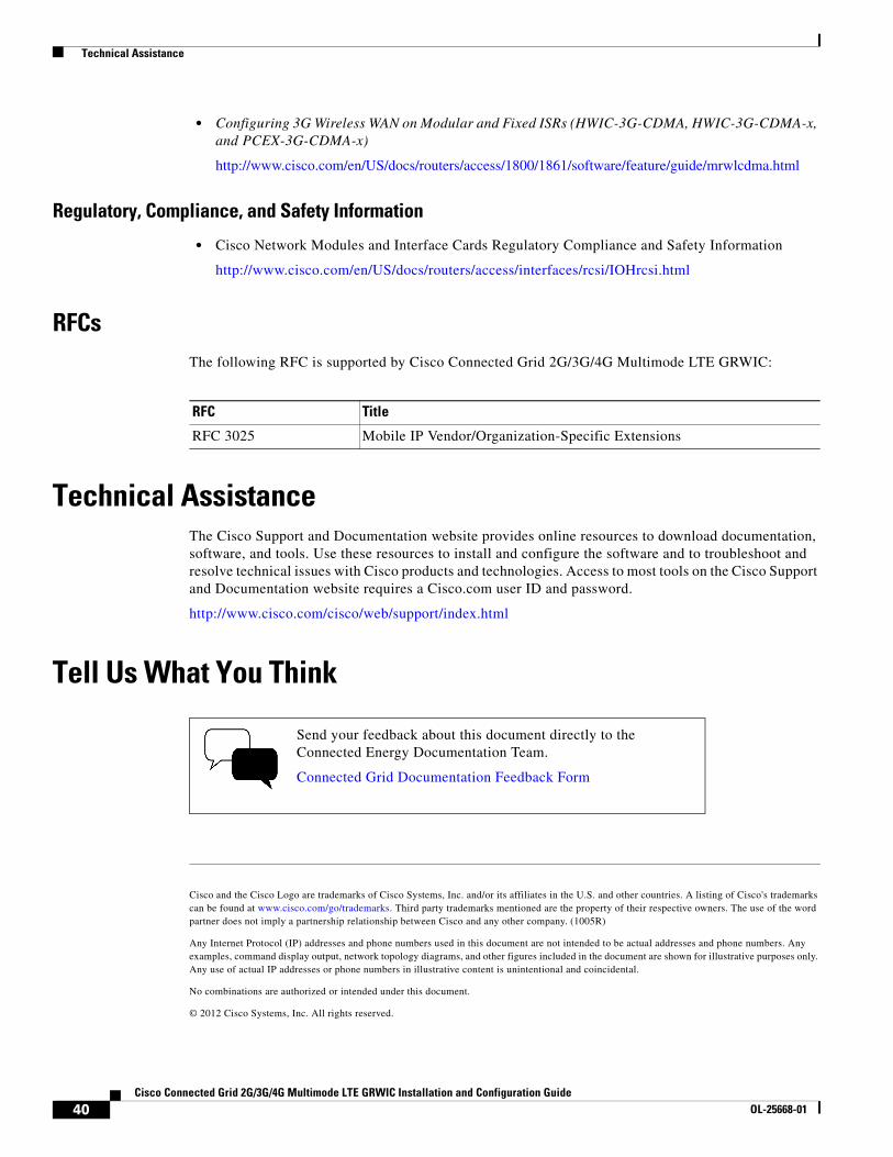
• Configuring 3G Wireless WAN on Modular and Fixed ISRs (HWIC-3G-CDMA, HWIC-3G-CDMA-x, and PCEX-3G-CDMA-x)
http://www.cisco.com/en/US/docs/routers/access/1800/1861/software/feature/guide/mrwlcdma.html
Regulatory, Compliance, and Safety Information
• Cisco Network Modules and Interface Cards Regulatory Compliance and Safety Information
http://www.cisco.com/en/US/docs/routers/access/interfaces/rcsi/IOHrcsi.html
RFCsThe following RFC is supported by Cisco Connected Grid 2G/3G/4G Multimode LTE GRWIC:
Technical AssistanceThe Cisco Support and Documentation website provides online resources to download documentation, software, and tools. Use these resources to install and configure the software and to troubleshoot and resolve technical issues with Cisco products and technologies. Access to most tools on the Cisco Support and Documentation website requires a Cisco.com user ID and password.
http://www.cisco.com/cisco/web/support/index.html
Tell Us What You Think
Cisco and the Cisco Logo are trademarks of Cisco Systems, Inc. and/or its affiliates in the U.S. and other countries. A listing of Cisco's trademarks can be found at www.cisco.com/go/trademarks. Third party trademarks mentioned are the property of their respective owners. The use of the word partner does not imply a partnership relationship between Cisco and any other company. (1005R)
Any Internet Protocol (IP) addresses and phone numbers used in this document are not intended to be actual addresses and phone numbers. Any examples, command display output, network topology diagrams, and other figures included in the document are shown for illustrative purposes only. Any use of actual IP addresses or phone numbers in illustrative content is unintentional and coincidental.
No combinations are authorized or intended under this document.
© 2012 Cisco Systems, Inc. All rights reserved.
RFC Title
RFC 3025 Mobile IP Vendor/Organization-Specific Extensions
Send your feedback about this document directly to the Connected Energy Documentation Team.
Connected Grid Documentation Feedback Form
40Cisco Connected Grid 2G/3G/4G Multimode LTE GRWIC Installation and Configuration Guide
OL-25668-01