Embed Size (px)
Citation preview
amjk 1
COBRA COBRA
Radio over Multimode Radio over Multimode FibreFibre NetworksNetworksTon Koonen, María García Larrodé, Hejie Yang
COBRA Institute dept. Electrical Engineering
Eindhoven University of Technologye-mail: [email protected]
Workshop on Optical/Wireless IntegrationOFC’08, San Diego, Feb. 25, 2008
COBRA COBRA
amjk 2
COBRA COBRA OutlineOutline
In-home network architecture for integrated broadband services
Radio-over-MMF using the Optical Frequency Multiplying technique
OFM system experiments
Reconfigurable Radio-over-MMF networks
Concluding remarks
amjk 3
COBRA COBRA Versatile BB inVersatile BB in--home networkshome networks
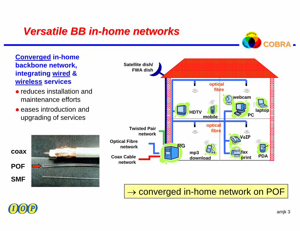
Converged in-homebackbone network,integrating wired &wireless services
reduces installation and maintenance effortseases introduction and upgrading of services
Coax Cable network
Twisted Pair network
RG
PCHDTVmobile
laptop
VoIP
faxprint PDA
mp3 download
Satellite dish/FWA dish
optical fibre
optical fibre
webcam
Optical Fibrenetwork
→ converged in-home network on POF
coax
POF
SMF
amjk 4
COBRA COBRA Radio over Radio over FibreFibre
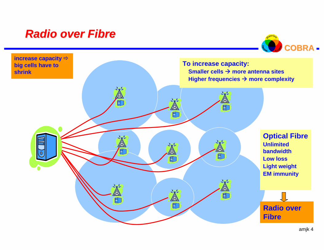
Optical FibreUnlimited bandwidth Low lossLight weightEM immunity
To increase capacity:Smaller cells more antenna sitesHigher frequencies more complexity
increase capacity big cells have to shrink
Radio over Fibre
amjk 5
COBRA COBRA Radio over multimode Radio over multimode fibrefibre
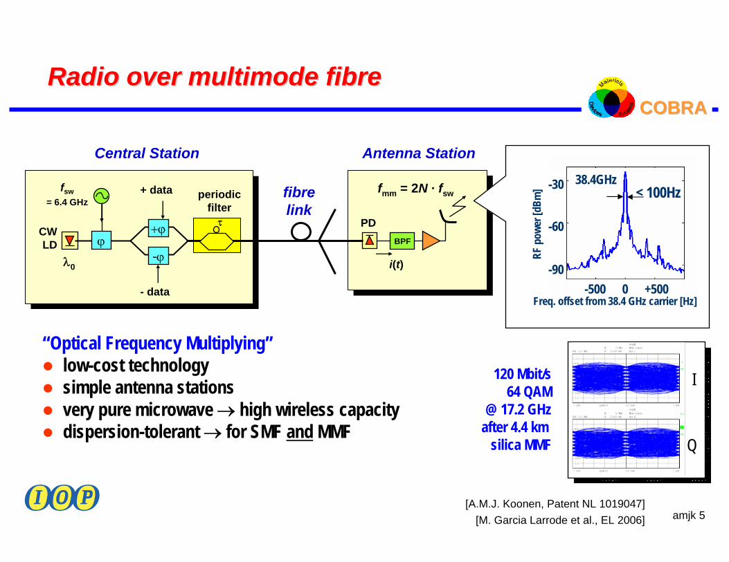
“Optical Frequency Multiplying”low-cost technologysimple antenna stationsvery pure microwave → high wireless capacitydispersion-tolerant → for SMF and MMF
[A.M.J. Koonen, Patent NL 1019047]
fsw= 6.4 GHz
CWLD
+ϕ
-ϕ
- data
PD
fibrelink
λ0
fmm = 2N · fsw
Central Station Antenna Station
BPF
i(t)
τ
periodic filter
+ data
I
Q
120 Mbit/s64 QAM
@ 17.2 GHzafter 4.4 km
silica MMF
Freq. offset from 38.4 GHz carrier [Hz]
38.4GHz< 100Hz
RF p
ower
[dBm
] -30
-60
-90-500 0 +500
ϕ
[M. Garcia Larrode et al., EL 2006]
amjk 6
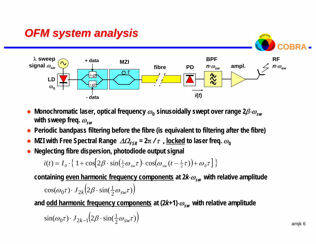
COBRA COBRA OFM system analysisOFM system analysis
Monochromatic laser, optical frequency ω0 sinusoidally swept over range 2β⋅ωswwith sweep freq. ωswPeriodic bandpass filtering before the fibre (is equivalent to filtering after the fibre)MZI with Free Spectral Range ∆ΩFSR = 2π / τ , locked to laser freq. ω0 Neglecting fibre dispersion, photodiode output signal
containing even harmonic frequency components at 2k⋅ωsw with relative amplitude
and odd harmonic frequency components at (2k+1)⋅ωsw with relative amplitude
( ) ( )[ ] τωτωτωβ 021
21
0 )(cossin2cos1)( +−⋅⋅+⋅= tIti swsw
( ))sin(2)cos( 21
20 τωβτω swkJ ⋅⋅
( ))sin(2)sin( 21
120 τωβτω swkJ ⋅⋅ −
fibre
LDω0
BPFn·ωswPD
λ sweepsignal ωsw ampl.
i(t)
τMZI
+ϕ
-ϕ
+ data
- data
RFn·ωsw
amjk 7
COBRA COBRA OFM generated microwave harmonics OFM generated microwave harmonics
-60
-50
-40
-30
-20
-10
0
1 2 3 4 5 6 7 8
β
pow
er n
th h
arm
onic
[dB
r]
n=1
2 34 5
61
-60
-50
-40
-30
-20
-10
0
1 2 3 4 5 6 7 8
β
pow
er n
th h
arm
onic
[dB
r]
n=1
2 34 5
61
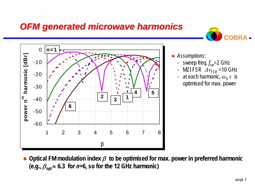
Optical FM modulation index β to be optimised for max. power in preferred harmonic(e.g., βopt ≈ 6.3 for n=6, so for the 12 GHz harmonic)
Assumptions:- sweep freq. fsw=2 GHz- MZI FSR ∆νFSR =10 GHz- at each harmonic, ω0 τ is
optimised for max. power
amjk 8
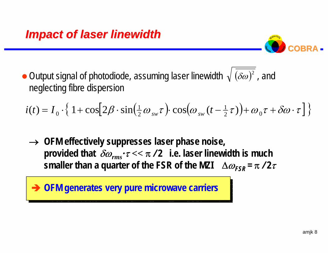
COBRA COBRA Impact of laser Impact of laser linewidthlinewidth
( ) ( )[ ] τδωτωτωτωβ ⋅++−⋅⋅+⋅= 021
21
0 )(cossin2cos1)( tIti swsw
Output signal of photodiode, assuming laser linewidth , and neglecting fibre dispersion
→ OFM effectively suppresses laser phase noise, provided that δωrms·τ << π / 2 i.e. laser linewidth is muchsmaller than a quarter of the FSR of the MZI ∆ωFSR = π / 2τ
OFM generates very pure microwave carriers
( )2δω
amjk 9
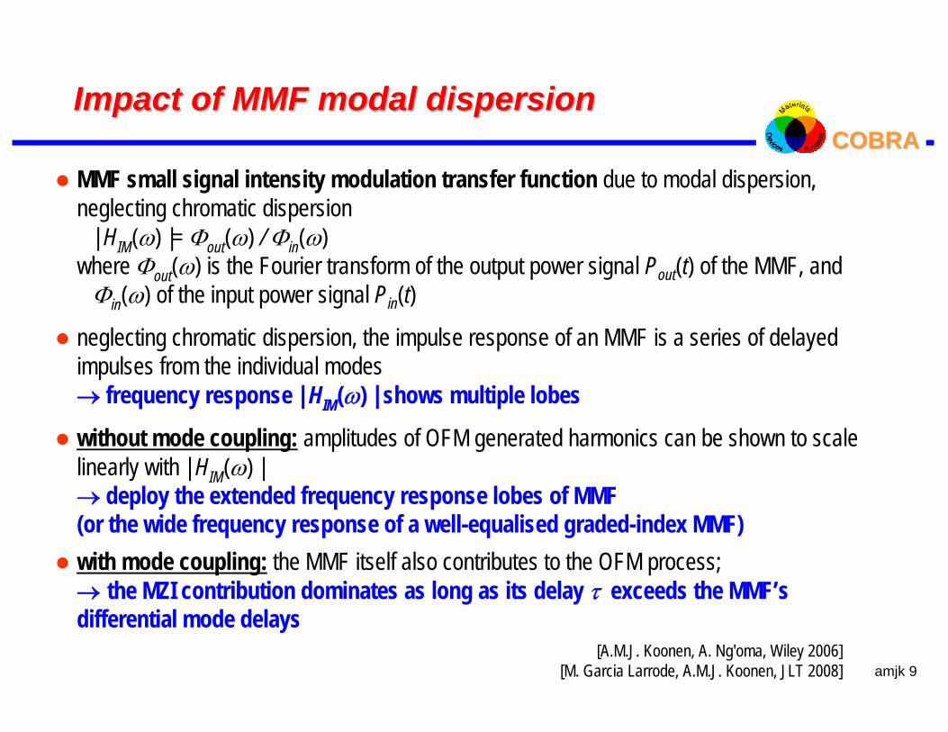
COBRA COBRA Impact of MMF modal dispersionImpact of MMF modal dispersion
MMF small signal intensity modulation transfer function due to modal dispersion, neglecting chromatic dispersion
| HIM(ω) |= Φout(ω) / Φin(ω)where Φout(ω) is the Fourier transform of the output power signal Pout(t) of the MMF, and
Φin(ω) of the input power signal Pin(t)
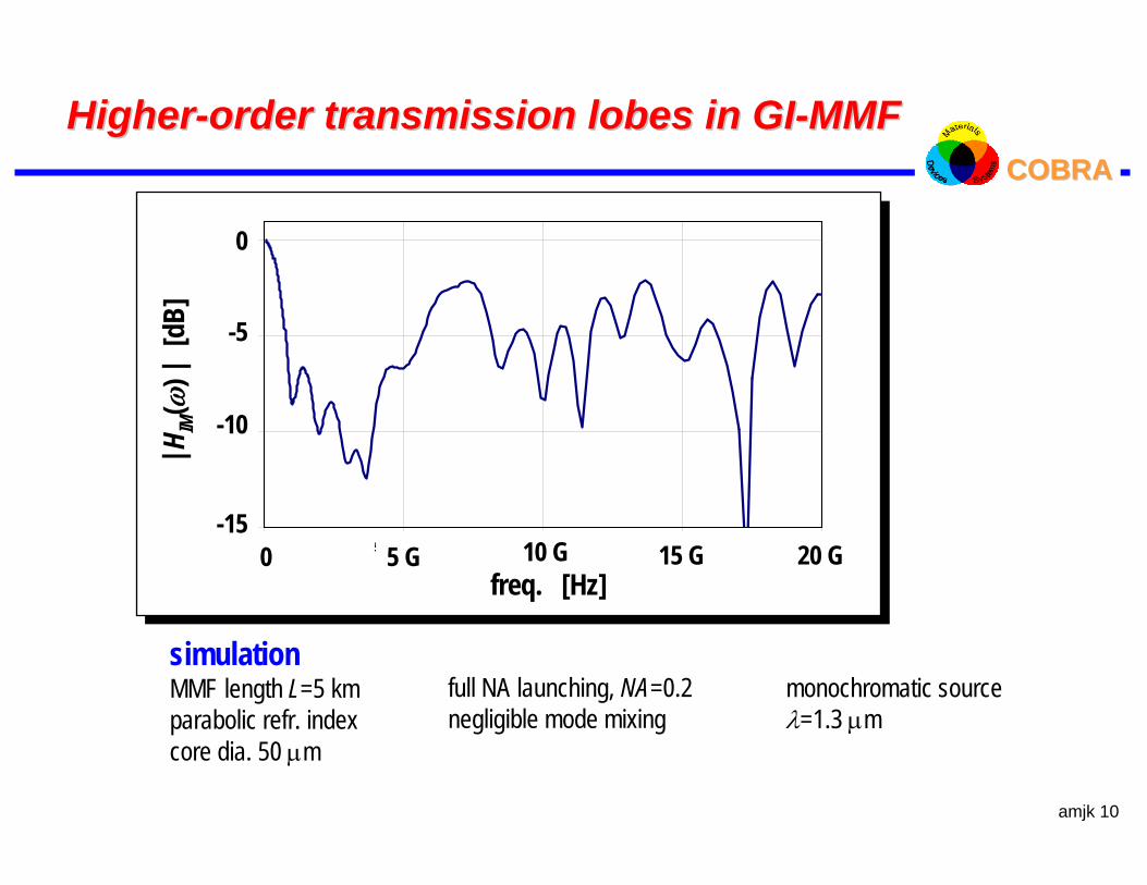
neglecting chromatic dispersion, the impulse response of an MMF is a series of delayedimpulses from the individual modes→ frequency response | HIM(ω) | shows multiple lobes
without mode coupling: amplitudes of OFM generated harmonics can be shown to scalelinearly with | HIM(ω) |→ deploy the extended frequency response lobes of MMF(or the wide frequency response of a well-equalised graded-index MMF)with mode coupling: the MMF itself also contributes to the OFM process; → the MZI contribution dominates as long as its delay τ exceeds the MMF’sdifferential mode delays
[A.M.J. Koonen, A. Ng'oma, Wiley 2006][M. Garcia Larrode, A.M.J. Koonen, JLT 2008]
amjk 10
COBRA COBRA HigherHigher--order transmission lobes in GIorder transmission lobes in GI--MMFMMF
-15
-10
-5
0
0.0E +00 5.0E +09 1.0E+10 1.5E+10 2.0E+10
fre q [Hz]
H_I
M [d
B]
simulationMMF length L=5 kmparabolic refr. indexcore dia. 50 µm
monochromatic sourceλ=1.3 µm
|HIM
(ω)|
[dB
]
freq. [Hz]5 G 10 G 15 G 20 G0
0
-5
-10
-15
full NA launching, NA=0.2negligible mode mixing

amjk 11
COBRA COBRA 6464--QAM experiment over silica GIQAM experiment over silica GI--MMFMMF
fsw=2.867 GHz
PM IM SOA MZI
VSG
4.4 kmMMFBPF
17.2 GHzVSA
LNA PD
LD1.3 µm
µ-wave carrier freq. 17.2 GHz64-QAM on subcarrier freq. 127 MHzsymbol rate 20 MBaud → 120 Mbit/sover 4.4 km silica GI-MMFalso over 25 km SMF @ 39.9 GHzmulti-tone (up to 10 tones) 64-QAM operation at 18.3 GHz over the GI-MMF link shown
EVM = 4.8 % (< 5.6 % req.)
I
Q
[A. Ng’oma et al., OFC2005]
VSG = Vector Signal GeneratorVSA = Vector Signal Analyzer
amjk 12
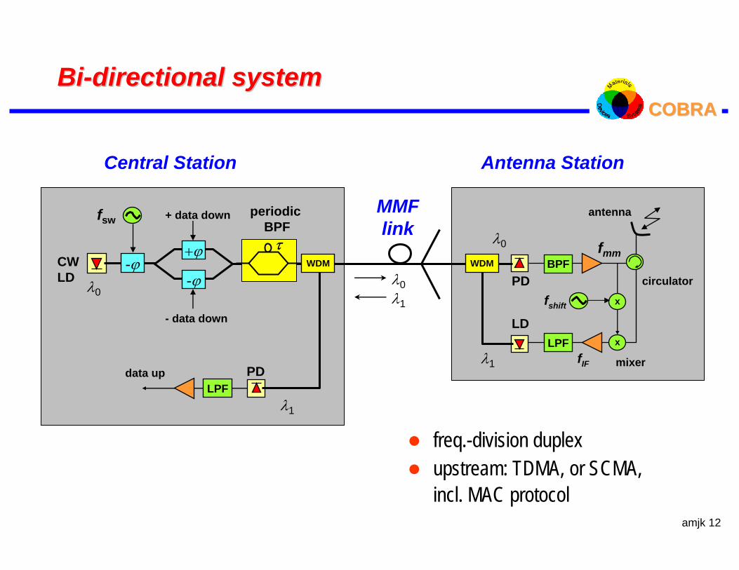
COBRA COBRA BiBi--directional systemdirectional system
freq.-division duplexupstream: TDMA, or SCMA,incl. MAC protocol
MMFlink
fsw
CWLD
+ϕ
-ϕ
- data down
λ0
Central Station
PDLPF
data up
+ data down
λ1
PD
Antenna Station
BPFfmm
xLPFLD
antenna
circulator
λ1
λ0
mixer
λ0λ1
WDM WDM
τ
periodic BPF
xfshift
fIF
-ϕ
amjk 13
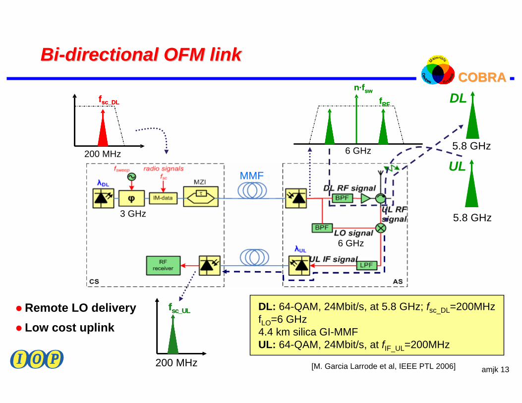
COBRA COBRA BiBi--directional OFM linkdirectional OFM link
Remote LO deliveryLow cost uplink
[M. Garcia Larrode et al, IEEE PTL 2006]
DL: 64-QAM, 24Mbit/s, at 5.8 GHz; fsc_DL=200MHzfLO=6 GHz4.4 km silica GI-MMFUL: 64-QAM, 24Mbit/s, at fIF_UL=200MHz
UL
5.8 GHz
DL
5.8 GHz
fsc_ULfsc_UL
200 MHz
6 GHz
3 GHz
MMF
200 MHz
fsc_DLfsc_DL fRF
n·fsw
fRF
n·fsw
6 GHz
amjk 14
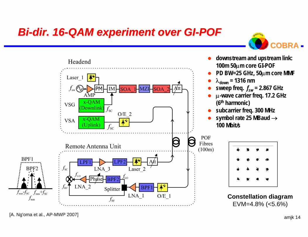
COBRA COBRA BiBi--dir. 16dir. 16--QAM experiment over GIQAM experiment over GI--POFPOF
downstream and upstream link: 100m 50µm core GI-POFPD BW=25 GHz, 50µm core MMFλdown = 1316 nmsweep freq. fsw = 2.867 GHzµ-wave carrier freq. 17.2 GHz (6th harmonic)subcarrier freq. 300 MHzsymbol rate 25 MBaud →100 Mbit/s
[A. Ng'oma et al., AP-MWP 2007]
Constellation diagramEVM=4.8% (<5.6%)
amjk 15
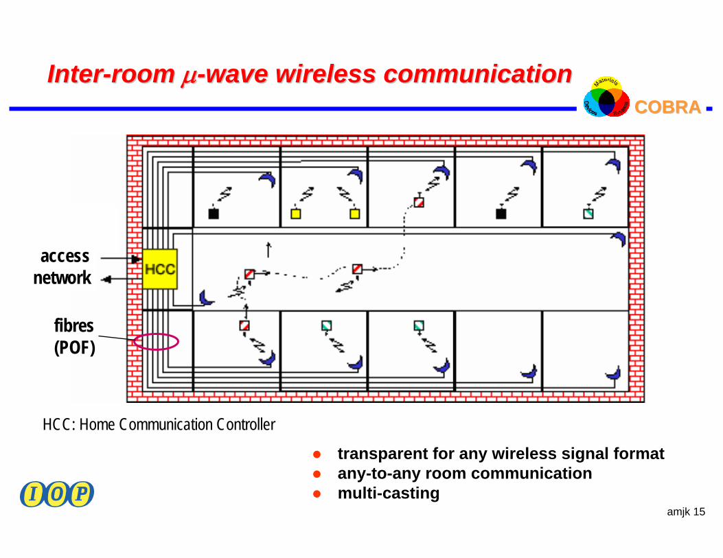
COBRA COBRA InterInter--room room µµ--wave wireless communicationwave wireless communication
transparent for any wireless signal formatany-to-any room communicationmulti-casting
HCC: Home Communication Controller
fibres(POF)
accessnetwork
amjk 16
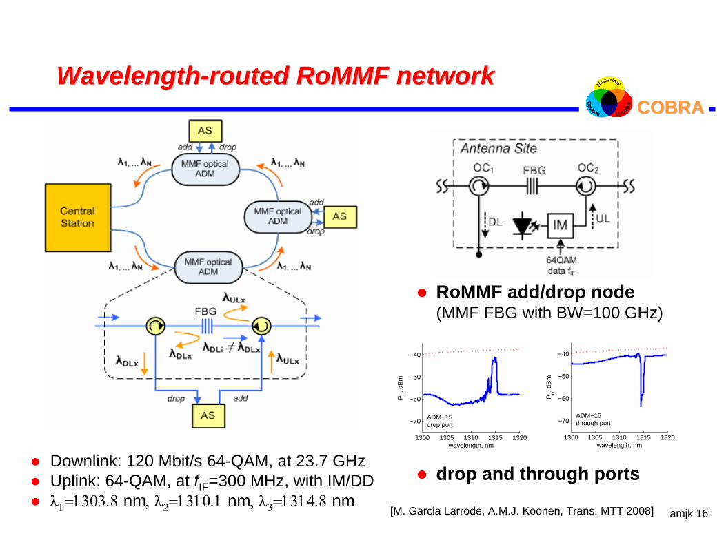
COBRA COBRA WavelengthWavelength--routed routed RoMMFRoMMF networknetwork
[M. Garcia Larrode, A.M.J. Koonen, Trans. MTT 2008]
1300 1305 1310 1315 1320
−70
−60
−50
−40
wavelength, nm
Po, d
Bm
ADM−15drop port
1300 1305 1310 1315 1320
−70
−60
−50
−40
wavelength, nm
Po, d
Bm
ADM−15through port
RoMMF add/drop node(MMF FBG with BW=100 GHz)
drop and through portsDownlink: 120 Mbit/s 64-QAM, at 23.7 GHzUplink: 64-QAM, at fIF=300 MHz, with IM/DDλ1=1303.8 nm, λ2=1310.1 nm, λ3=1314.8 nm

amjk 17
COBRA COBRA Concluding remarksConcluding remarks
Future-proof, versatile and high-capacity service provisioning of multiple services in in-home networks can efficiently be done using silica or polymermultimode fibre.
Radio-over-fibre facilitates the overlay of wireless communication services in a wired infrastructure, and the convergence of wirebound and wireless services in In-Home networks.
With the Optical Frequency Multiplying technique microwave radio signals with high spectral purity and high capacity can be generated, and transported over dispersive multimode (and single-mode) fibre links.
In combination with flexible wavelength routing, reconfigurable multi-standard wireless pico-cell LANs can be created.
amjk 18
COBRA COBRA AcknowledgementAcknowledgement
Funding from
the European Commission, in FP7 project ALPHA – Architectures for fLexible Photonic Homeand Access networks,FP6 Network of Excellence e-Photon/ONe +,FP6 Network of Excellence ISIS,FP7 Network of Excellence BONE
the Dutch Ministry of Economic Affairs, in the IOP Generieke Communicatie projectsRoF Broadband In-House Systems and Future Home Networks
is gratefully acknowledged.