Embed Size (px)
Citation preview
CFD SIMULATION OF SWIRL FLOW IN HEXAGONAL ROD BUNDLE GEOMETRY BY
SPLIT MIXING VANE GRID SPACERS
Mohammad NAZIFIFARD
Department of Energy Systems Engineering, Energy Research Institute, University of Kashan,
Kashan, Iran
Heat transfer and pressure drop are numerically investigated for turbulent
flows through a hexagonal fuel rod bundle. For the purpose of numerical
analysis, the geometric and boundary conditions were taken from the VVER-
1000. Since VVER-1000 does not have mixing vane on the grid spacer of the
fuel assembly, Split mixing vane is designed to boost turbulent flow and heat
transfer in the rod bundle subchannels. The computational domain including
two grid spacers extend from 100×Dh upstream of the first grid spacer to
250×Dh downstream of the second grid spacer. The steady state form of the
Reynolds-averaged Navier-Stokes (RANS), mass, energy and turbulence
equations was discretized and solved using Ansys-CFX. The standard k-
epsilon model is employed to simulate turbulence. The results show a
considerable increase in the average heat transfer to ~10×Dh downstream of
the grid spacer using the mixing vane on the grid spacer of VVER type
reactor. As expected, the pressure loss through the grid spacer also
increased slightly with the mixing vanes.
Key words: Pressurised water reactor, VVER 1000, Mixing vane, Heat
transfer enhancement, Computational fluid dynamics, Turbulence model.
1. Introduction
In the pressurized water reactor (PWR) work, the coolant is in the forced and turbulent
convection. The average heat transfer coefficient in force convection is genraly governed by those
factors representing turbulence and operating conditions. Generally, a larger and more uniform single
phase local heat transfer coefficient yields increased performance, and prevents the nuclear fuel rods
from potential damage by increased temperature. There are different methods to enhance the local heat
transfer rate in the PWR core. The mixing vanes grid spacers are one of the most widely used groups
of heat transfer enhancement tools to boost turbulent flow and heat transfer in the PWR fuel
subchannels. The grid spacers and mixing vanes have since 1970s undergone gradual development in
order to improve their performance [1-13]. Preliminary experimental analysis of PWR grid spacer was
undertaken by Rehme [1-3] that resulted in correlations for several grid spacers without mixing vanes.
Also, in the field of experimental study related to heat transfer, several researcher [4-7] showed locally
enhanced heat transfer downstream of the grid spacer in the PWR rod bundles. Schikorr et al. [14]
improved Rehme’s correlation to include grid spacers with mixing devices based on new pressure drop
measurements. Morovere, recent studies [15-31] have reported that the mixing vanes cause cross and
swirl flows amongst and within the subchannels enhancing heat transfer in the vicinity of the grid
spacer. However, the main role of the mixing vane in the rod bundle is the enhancement of Critical
Heat Flux (CHF) and departure from nucleate boiling (DNB) which could contribute to the
improvement of reactor safety [12 and 27]. A study by Song et al. [12] showed the standard split vane
could enhance the CHF by up to 14.5 % when compared with the grid spacer without a mixing vane
for PWRs. Albeit the DNB phenomenon for nuclear rod bundle is analyzed by CFD under a two phase
flow condition, the distribution of fluid enthalpy and the Nusselt number Nu under a single phase flow
will determine the initial conditions and important information regarding the two phase flow structure
[10,15]. However, a major problem with the mixing vane is the additional pressure drop which could
increase the reactor pumping costs. The pressure drop depends on the grid spacer and mixing vane
design. Numerous studies have showed [13, 28, 30, 31] that the addition of mixing vane on the grid
spacer generates more anisotropic axial swirling pattern compared against the standard grid spacer.
Nematollahi and Nazifi [13] showed that the standard split mixing vane is expected to significantly
enhance the overall heat transfer of a nuclear fuel assembly by 9.82% with a reasonable increase in the
pumping cost. Tóth and Aszódi [16] emphasized that the grid spacer has an important bearing on the
cross flows, axial velocity and outlet temperature distribution in subchannels. Tóth and Aszódi [17] in
another CFD study improved the full length fuel bundle and 60° segment model for a VVER-440 fuel
assembly. They proved that the coolant mixing is more intensive in the fuel assembly head than in the
rod bundle. The CFD analysis revealed that the outflow from the central tube influences strongly the
in-core temperature measurement. Therefore this effect has to be taken into account in VVER
assembly head calculations. Hutli et al. [26] investigated experimentally the increase of mixing
phenomenon in a coolant flow in order to improve the heat transfer, the economical operation and the
structural integrity of VVER-440 using PIV and PLIF techniques. They obtained detailed information
on the velocity, turbulence and temperature distribution for parallel turbulent flows through sub-
channels of a hexagonal VVER-type rod bundle.
The literature survey ended up no data to be found on the presence of a mixing vane on the grid
spacer of VVER 1000. In addition, there is a scarcity of work done for design of a mixing vane for the
VVER type reactor. In this study, Split mixing vanes are designed for VVER-1000. A CFD analysis is
performed to analyse the heat transfer and additional pressure drop on the mixing vane.
2. Numerical Simulation
For the purpose of simulations, the geometry and boundary conditions were extracted from the
VVER-1000 core. The VVER-1000 is a Russian designed Pressurised Water Reactors (PWR) with a
hexagonal fuel assembly geometry. In western PWR, the mixing vanes are attached to the grid spacers
of rod bundle to enhance thermal performance by promoting the turbulence level, increasing inter-
subchannel mixing, and inducing swirl flows. Since VVER-1000 does not have mixing vane on the
grid spacer of the fuel assembly, mixing vane is designed to boost turbulent flow and heat transfer in
the rod bundle subchannels. The mixing vane in this study is similar with the standard split vane of
ordinary PWRs except that it is customized for VVER-1000. The mixing vanes may as well be
incorporated in the actual rod bundle for VVER-1000. The clockwise swirling arrangement is applied
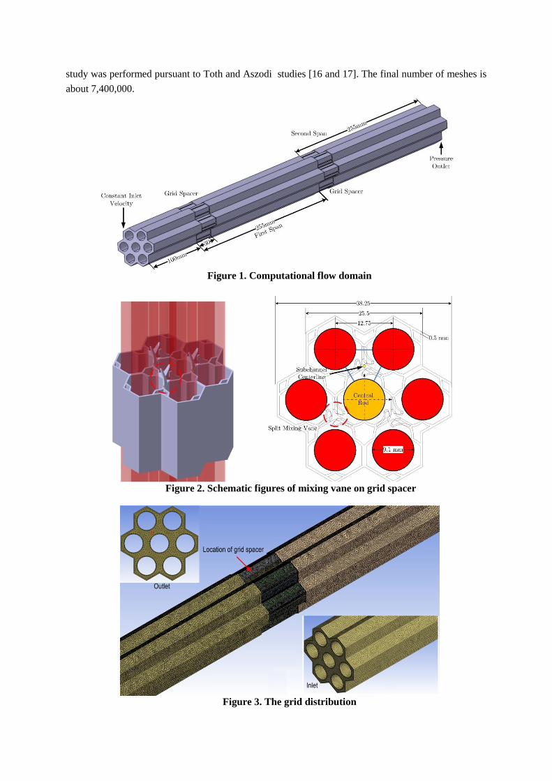
for the mixing vanes. The computational domain consists of 610 mm long models containing 7 fuel
rods of VVER-1000 rod bundle with an outer diameter of 9.1 mm and the rod pitch of 12.3 mm (Fig.
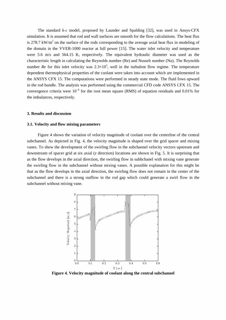
1). The grid spacer was modeled considering its wall thickness. The cross-sectional area of the model
and the grid spacer are depicted in Fig. 2. The unstructured meshes were applied in the center of
channels, and fine layers close to the walls. Cross sectional grid distribution is depicted in Fig. 3.
Unstructured meshes in the center of channels region and fine layers close to the walls were applied.
In order to check on the influence of the mesh resolution on the results and to minimize the numerical
influences introduced by the size of meshes and their distributions, comprehensive mesh sensitivity
study was performed pursuant to Toth and Aszodi studies [16 and 17]. The final number of meshes is
about 7,400,000.
Figure 1. Computational flow domain
Figure 2. Schematic figures of mixing vane on grid spacer
Figure 3. The grid distribution
The standard k-ε model, proposed by Launder and Spalding [32], was used in Ansys-CFX
simulation. It is assumed that rod and wall surfaces are smooth for the flow calculations. The heat flux
is 278.7 kW/m2 on the surface of the rods corresponding to the average axial heat flux in modeling of
the domain in the VVER-1000 reactor at full power [15]. The water inlet velocity and temperature
were 5.6 m/s and 564.15 K, respectively. The equivalent hydraulic diameter was used as the
characteristic length in calculating the Reynolds number (Re) and Nusselt number (Nu). The Reynolds
number Re for this inlet velocity was 2.3×10⁵, well in the turbulent flow regime. The temperature
dependent thermophysical properties of the coolant were taken into account which are implemented in
the ANSYS CFX 15. The computations were performed in steady state mode. The fluid fows upward
in the rod bundle. The analysis was performed using the commercial CFD code ANSYS CFX 15. The
convergence criteria were 10−6
for the root mean square (RMS) of equation residuals and 0.01% for
the imbalances, respectively.
3. Results and discussion
3.1. Velocity and flow mixing parameters
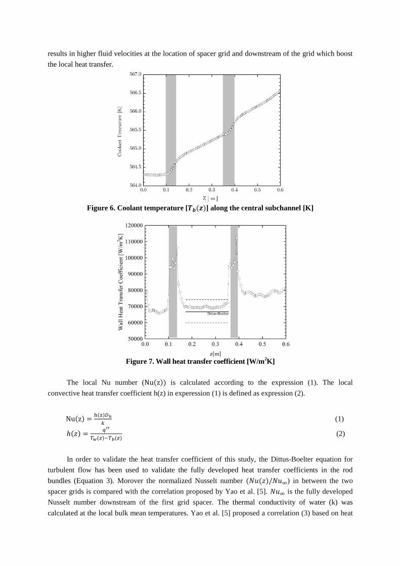
Figure 4 shows the variation of velocity magnitude of coolant over the centerline of the central
subchannel. As depicted in Fig. 4, the velocity magnitude is shaped over the grid spacer and mixing
vanes. To show the development of the swirling flow in the subchannel velocity vectors upstream and
downstream of spacer grid at six axial (z direction) locations are shown in Fig. 5. It is surprising that
as the flow develops in the axial direction, the swirling flow in subhchanel with mixing vane generate
the swirling flow in the subchannel without mixing vanes. A possible explanation for this might be
that as the flow develops in the axial direction, the swirling flow does not remain in the center of the
subchannel and there is a strong outflow in the rod gap which could generate a swirl flow in the
subchannel without mixing vane.
Figure 4. Velocity magnitude of coolant along the central subchannel
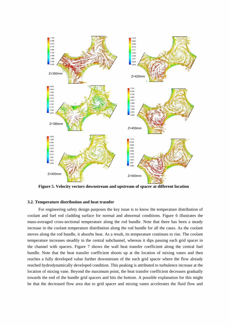
Figure 5. Velocity vectors downstream and upstream of spacer at different location
3.2. Temperature distribution and heat trasnfer
For engineering safety design purposes the key issue is to know the temperature distribution of
coolant and fuel rod cladding surface for normal and abnormal conditions. Figure 6 illustrates the
mass-averaged cross-sectional temperature along the rod bundle. Note that there has been a steady
increase in the coolant temperature distribution along the rod bundle for all the cases. As the coolant
moves along the rod bundle, it absorbs heat. As a result, its temperature continues to rise. The coolant
temperature increases steadily in the central subchannel, whereas it dips passing each grid spacer in
the channel with spacers. Figure 7 shows the wall heat transfer coefficient along the central fuel
bundle. Note that the heat transfer coefficient shoots up at the location of mixing vanes and then
reaches a fully developed value further downstream of the each grid spacer where the flow already
reached hydrodynamically developed condition. This peaking is attributed to turbulence increase at the
location of mixing vane. Beyond the maximum point, the heat transfer coefficient decreases gradually
towards the end of the bundle grid spacers and hits the bottom. A possible explanation for this might
be that the decreased flow area due to grid spacer and mixing vanes accelerates the fluid flow and
results in higher fluid velocities at the location of spacer grid and downstream of the grid which boost
the local heat transfer.
Figure 6. Coolant temperature [ ] along the central subchannel [K]
Figure 7. Wall heat transfer coefficient [W/m
2K]
The local Nu number ( is calculated according to the
expression (1). The local
convective heat transfer coefficient h(z) in experession (1) is defined as expression (2).
(1)
(2)
In order to validate the heat transfer coefficient of this study, the Dittus-Boelter equation for
turbulent flow has been used to validate the fully developed heat transfer coefficients in the rod
bundles (Equation 3). Morover the normalized Nusselt number ) in between the two
spacer grids is compared with the correlation proposed by Yao et al. [5]. is the fully developed
Nusselt number downstream of the first grid spacer. The thermal conductivity of water (k) was
calculated at the local bulk mean temperatures. Yao et al. [5] proposed a correlation (3) based on heat
transfer measurements from rod bundles with spacer grids in an experimental test facility with gas
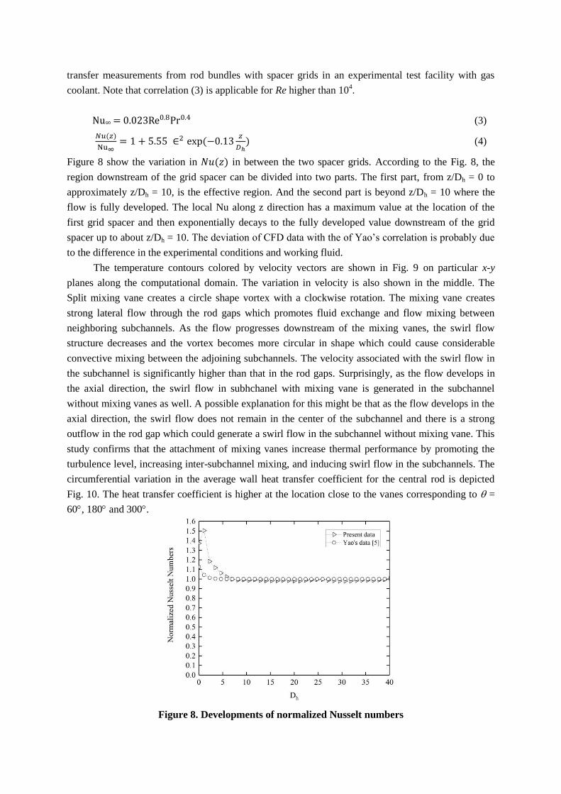
coolant. Note that correlation (3) is applicable for Re higher than 104.
(3)
(4)
Figure 8 show the variation in in between the two spacer grids. According to the Fig. 8, the
region downstream of the grid spacer can be divided into two parts. The first part, from z/Dh = 0 to
approximately z/Dh = 10, is the effective region. And the second part is beyond z/Dh = 10 where the
flow is fully developed. The local Nu along z direction has a maximum value at the location of the
first grid spacer and then exponentially decays to the fully developed value downstream of the grid
spacer up to about z/Dh = 10. The deviation of CFD data with the of Yao’s correlation is probably due
to the difference in the experimental conditions and working fluid.
The temperature contours colored by velocity vectors are shown in Fig. 9 on particular x-y
planes along the computational domain. The variation in velocity is also shown in the middle. The
Split mixing vane creates a circle shape vortex with a clockwise rotation. The mixing vane creates
strong lateral flow through the rod gaps which promotes fluid exchange and flow mixing between
neighboring subchannels. As the flow progresses downstream of the mixing vanes, the swirl flow
structure decreases and the vortex becomes more circular in shape which could cause considerable
convective mixing between the adjoining subchannels. The velocity associated with the swirl flow in
the subchannel is significantly higher than that in the rod gaps. Surprisingly, as the flow develops in
the axial direction, the swirl flow in subhchanel with mixing vane is generated in the subchannel
without mixing vanes as well. A possible explanation for this might be that as the flow develops in the
axial direction, the swirl flow does not remain in the center of the subchannel and there is a strong
outflow in the rod gap which could generate a swirl flow in the subchannel without mixing vane. This
study confirms that the attachment of mixing vanes increase thermal performance by promoting the
turbulence level, increasing inter-subchannel mixing, and inducing swirl flow in the subchannels. The
circumferential variation in the average wall heat transfer coefficient for the central rod is depicted
Fig. 10. The heat transfer coefficient is higher at the location close to the vanes corresponding to =
60, 180 and 300.
Figure 8. Developments of normalized Nusselt numbers
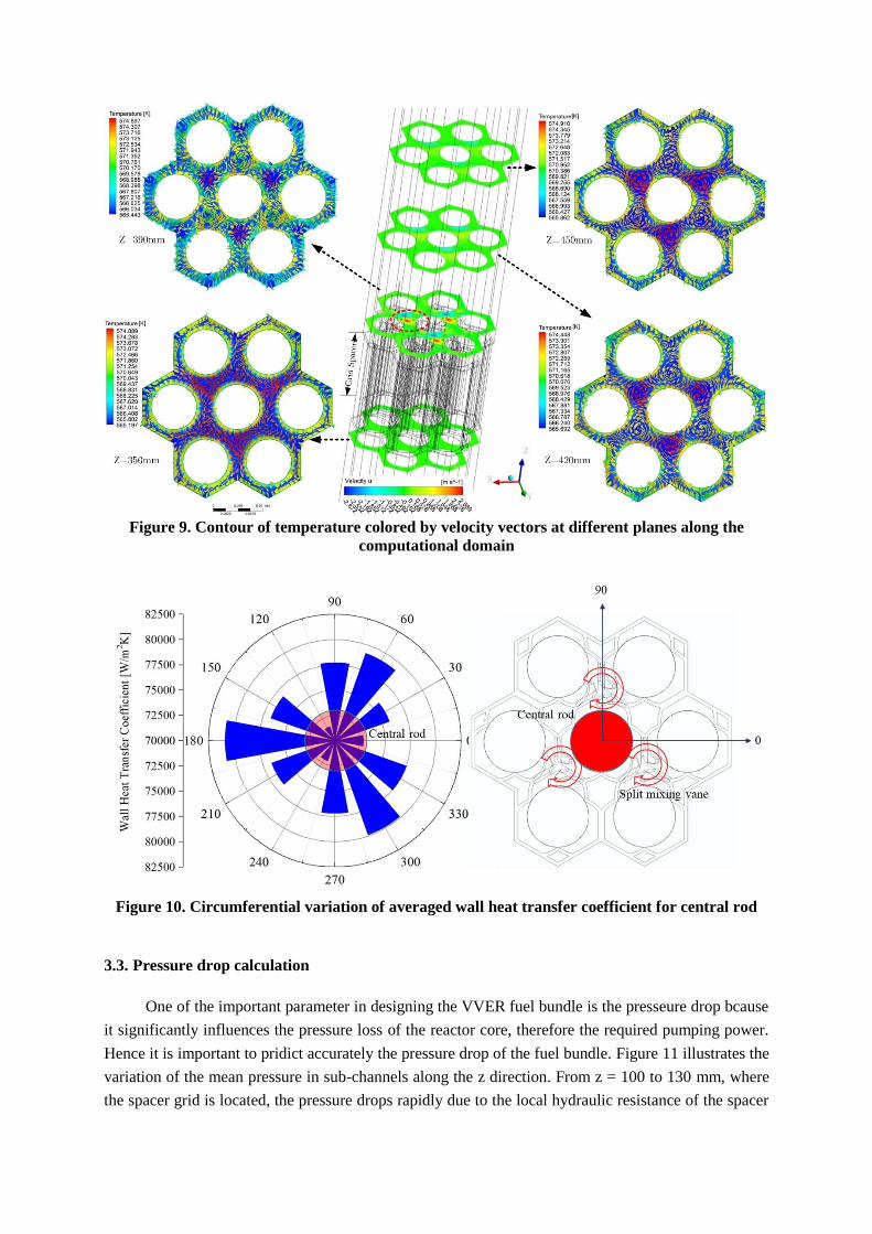
Figure 9. Contour of temperature colored by velocity vectors at different planes along the
computational domain
Figure 10. Circumferential variation of averaged wall heat transfer coefficient for central rod
3.3. Pressure drop calculation
One of the important parameter in designing the VVER fuel bundle is the presseure drop bcause
it significantly influences the pressure loss of the reactor core, therefore the required pumping power.
Hence it is important to pridict accurately the pressure drop of the fuel bundle. Figure 11 illustrates the
variation of the mean pressure in sub-channels along the z direction. From z = 100 to 130 mm, where
the spacer grid is located, the pressure drops rapidly due to the local hydraulic resistance of the spacer
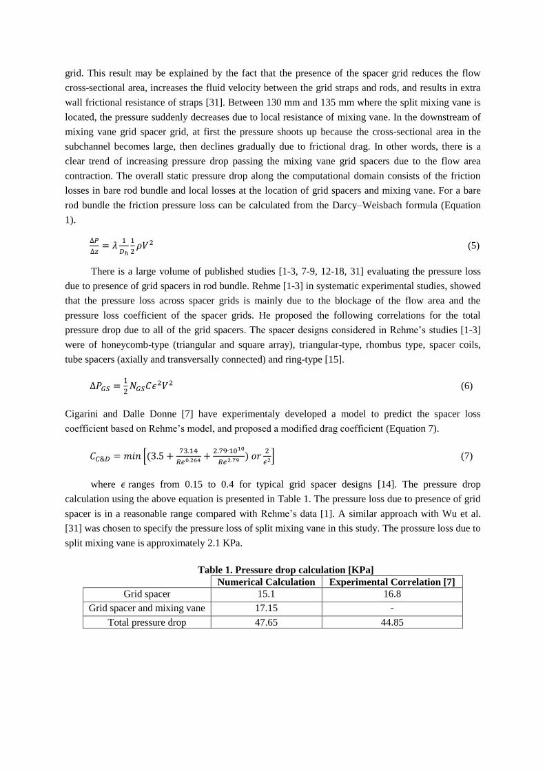
grid. This result may be explained by the fact that the presence of the spacer grid reduces the flow
cross-sectional area, increases the fluid velocity between the grid straps and rods, and results in extra
wall frictional resistance of straps [31]. Between 130 mm and 135 mm where the split mixing vane is
located, the pressure suddenly decreases due to local resistance of mixing vane. In the downstream of
mixing vane grid spacer grid, at first the pressure shoots up because the cross-sectional area in the
subchannel becomes large, then declines gradually due to frictional drag. In other words, there is a
clear trend of increasing pressure drop passing the mixing vane grid spacers due to the flow area
contraction. The overall static pressure drop along the computational domain consists of the friction
losses in bare rod bundle and local losses at the location of grid spacers and mixing vane. For a bare
rod bundle the friction pressure loss can be calculated from the Darcy–Weisbach formula (Equation
1).
(5)
There is a large volume of published studies [1-3, 7-9, 12-18, 31] evaluating the pressure loss
due to presence of grid spacers in rod bundle. Rehme [1-3] in systematic experimental studies, showed
that the pressure loss across spacer grids is mainly due to the blockage of the flow area and the
pressure loss coefficient of the spacer grids. He proposed the following correlations for the total
pressure drop due to all of the grid spacers. The spacer designs considered in Rehme’s studies [1-3]
were of honeycomb-type (triangular and square array), triangular-type, rhombus type, spacer coils,
tube spacers (axially and transversally connected) and ring-type [15].
(6)
Cigarini and Dalle Donne [7] have experimentaly developed a model to predict the spacer loss
coefficient based on Rehme’s model, and proposed a modified drag coefficient (Equation 7).
(7)
where ranges from 0.15 to 0.4 for typical grid spacer designs [14]. The pressure drop
calculation using the above equation is presented in Table 1. The pressure loss due to presence of grid
spacer is in a reasonable range compared with Rehme’s data [1]. A similar approach with Wu et al.
[31] was chosen to specify the pressure loss of split mixing vane in this study. The prossure loss due to
split mixing vane is approximately 2.1 KPa.
Table 1. Pressure drop calculation [KPa]
Numerical Calculation Experimental Correlation [7]
Grid spacer 15.1 16.8
Grid spacer and mixing vane 17.15 -
Total pressure drop 47.65 44.85
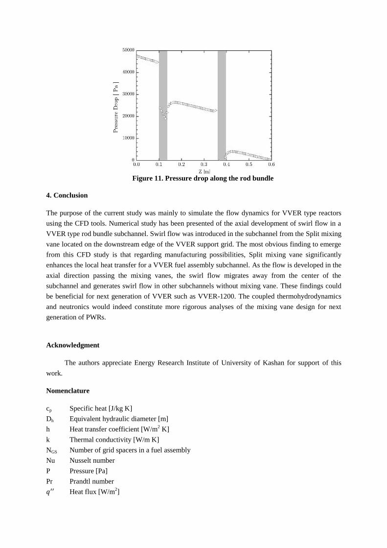
Figure 11. Pressure drop along the rod bundle
4. Conclusion
The purpose of the current study was mainly to simulate the flow dynamics for VVER type reactors
using the CFD tools. Numerical study has been presented of the axial development of swirl flow in a
VVER type rod bundle subchannel. Swirl flow was introduced in the subchannel from the Split mixing
vane located on the downstream edge of the VVER support grid. The most obvious finding to emerge
from this CFD study is that regarding manufacturing possibilities, Split mixing vane significantly
enhances the local heat transfer for a VVER fuel assembly subchannel. As the flow is developed in the
axial direction passing the mixing vanes, the swirl flow migrates away from the center of the
subchannel and generates swirl flow in other subchannels without mixing vane. These findings could
be beneficial for next generation of VVER such as VVER-1200. The coupled thermohydrodynamics
and neutronics would indeed constitute more rigorous analyses of the mixing vane design for next
generation of PWRs.
Acknowledgment
The authors appreciate Energy Research Institute of University of Kashan for support of this
work.
Nomenclature
cp Specific heat [J/kg K]
Dh Equivalent hydraulic diameter [m]
h Heat transfer coefficient [W/m2 K]
k Thermal conductivity [W/m K]
NGS Number of grid spacers in a fuel assembly
Nu Nusselt number
P Pressure [Pa]
Pr Prandtl number
Heat flux [W/m2]
Re Reynolds number
T Temperature [K]
v Velocity component [m/s]
x, y, z Spatial coordinates [m]
Mean velocity (Re averaged)
Greek symbols
μ Dynamic viscosity [Pa.s]
ρ Density, [kg/m3]
Vane angle []
Subchannel blockage factor
Subscript
av average
b bulk
in inlet section
out outlet section
w wall
value at fully developed region
References
[1] Rehme, K., Pressure Drop Correlations for Fuel Element Spacers, Nuclear Technology, 17 (1973),
1, pp.15-23.
[2] Rehme, K., Pressure Drop of Spacer Grids in Smooth and Roughened Rod Bundles, Nuclear
Technology, 33 (1977), 3, pp. 314-317.
[3] Rehme, K. Trippe, G., Pressure Drop and Velocity Distribution in Rod Bundles with Spacer Grids,
Nuclear Engineering and Design, 62 (1980), 1-3, pp. 349-359.
[4] Bragina, V.L., et al., Experimental Study of Enhancement of Heat Transfer From a Tube Bundle in
Turbulent Axial Flow, Heat transfer: Soviet research, 13 (1981), 4, pp. 14–18.
[5] Yao, S.C., et al., Heat Transfer Augmentation in Rod Bundle Near Grid Spacers, Journal of Heat
Transfer, 104 (1982), pp. 76-81.
[6] Chesna, B.A., Kolesnikovas, I.Y., Influence of Spacer Grids on the Rate of Heat Transfer in an Air
Stream Flowing Longitudinally Through a Bundle of Rods, International Chemical Engineering,
27 (1987), 1, pp. 158–161.
[7] Cigarini M., Dalle Donne M., Thermohydraulic Optimization of Homogeneous and Heterogeneous
Advanced Pressurized Reactors, Nuclear Technology, 80 (1988), pp. 107–132.
[8] In, W.K., et al., Flow Analysis for Optimum Design of Mixing Vane in a PWR Fuel Assembly,
Journal of the Korean Nuclear Society, 33 (2001), 3, 327.
[9] Kim, K.Y., Seo, J.W., Shape Optimization of a Mixing Vane in Subchannel of Nuclear Reactor,
Journal of Nuclear Science and Technology, 41(2004), 5, pp. 641–644.
[10] Ikeda, K., et al., Single-phase CFD Applicability for Estimating Fluid Hot-Spot Locations in a 5
× 5 Fuel Rod Bundle, Nuclear Engeering Design, 236 (2006), 1149-1154.
[11] Ikeno, T., et al., The Effect of Mixing Vane Arrangements in a Subchannel Turbulent Flow,
Journal of Nuclear Science and Technology, 43 (2006), 10, 1194-1205.
[12] Song, K.N., et al., Performance Evaluation of New Spacer Grid Shapes for PWRs, Journal of the
Korean Nuclear Society, 39 (2007), 6, 737-347.
[13] Nematollahi, M.R., Nazifi, M., Enhancement of Heat Transfer in a Typical Pressurized Water
Reactor by Different Mixing Vanes on Spacer Grids, Energy Conversion Management, 49 (2008),
1981-1988.
[14] Schikorr M., et al., Proposal for Pressure Drop Prediction for a Fuel Bundle with Grid Spacers
using Rehme Pressure Drop Correlations, Nuclear Engineering Design, 240 (2010), 7, 1830-1842.
[15] Ganjiani, H., Firoozabadi, B., Three-dimensional Simulation of Turbulent Flow in 3-sub
Channels of a VVER-1000 Reactor, Sharif University of Technology Transaction B: Mechanical
Engineering, 17 (2010), 2, 83-92.
[16] Tóth, S., Aszódi, A., CFD Analysis of Flow Field in a Triangular Rod Bundle, Nuclear
Engineering Design, 240 (2010), 2, 352-363.
[17] Tóth, S., Aszódi, A., CFD Study on Coolant Mixing in VVER-440 Fuel Rod Bundles and Fuel
Assembly Heads, Nuclear Engineering Design, 240 (2010), 9, 2194-2205.
[18] Navarro, M.A., Santos, A.C., Evaluation of a Numeric Procedure for Flow Simulation of a 5 × 5
PWR Rod Bundle with a Mixing Vane Spacer, Progress of Nuclear Energy, 53 (2011), pp. 1190-
1196.
[19] Sang-Ki, M., et al., Single-phase Convective Heat Transfer Enhancement by Spacer Grids in a
Rod Bundle, Journal of Nuclear Science and Technology, 51 (2014), 4, 543-557.
[20] Chang, S.K., et al., Turbulent Mixing in a Rod Bundle with Vaned Spacer Grids: OECD/NEA–
KAERI CFD Benchmark Exercise Test, Nuclear Engineering and Design, 279 (2014), pp.19-36.
[21] Lee, J.R., et al., Synthesis of the Turbulent Mixing in a Rod Bundle with Vaned Spacer Grids
Based on the OECD-KAERI CFD Benchmark Exercise, Nuclear Engineering and Design, 279
(2014), pp.3-1.
[22] Cinosi, N., et al., CFD Simulation of Turbulent Flow in a Rod Bundle with Spacer Grids
(MATIS-H) using STAR-CCM+, Nuclear Engineering and Design, 279 (2014), pp.37-49.
[23] Bieder, U., et al., LES Analysis of the Flow in a Simplified PWR Assembly with Mixing
Grid, Progress in Nuclear Energy, 75 (2014), pp.15-24.
[24] In, W.K., et al., Measurement and CFD Calculation of Spacer Loss Coefficient for a Tight-
Lattice Fuel Bundle, Nuclear Engineering and Design, 284 (2015), pp.153-161.
[25] Lee, et al., Augmentation of Single-phase Forced Convection Heat Transfer in Tightly Arrayed
Rod Bundle with Twist-Vane Spacer Grid, Experimental Thermal and Fluid Science, 76 (2016),
185-192.
[26] Hutli, E., et al., Experimental Approach to Investigate the Dynamics of Mixing Coolant Flow in
Complex Geometry using PIV and PLIF Techniques. Thermal Science, 19 (2015), pp.989-1004.
[27] Qin, S., et al., Experimental Investigation on Repeatability of CHF in Rod bundle with non-
uniform Axial Heat Flux Distribution, Progress in Nuclear Energy, 90 (2016), pp.151-154.
[28] Mao, H., et al., Modeling of Spacer Grid Mixing Effects through Mixing Vane Crossflow Model
in Subchannel Analysis, Nuclear Engineering and Design, 320 (2017), 141-152.
[29] Chen, X., et al., Validation of CFD Analysis for Rod Bundle Flow Test with Vaned Spacer
Grids., Annals of Nuclear Energy, 109 (2017): 370-379.
[30] Shashi Kant, V. et al., Experimental Investigation of Effect of Spacer on Single Phase Turbulent
Mixing Rate on Simulated Subchannel of Advanced Heavy Water Reactor, Annals of Nuclear
Energy, 110 (2017), pp. 186-195.
[31] Wu, J. M. , et al., CFD Analysis of the Impact of a Novel Spacer Grid with Longitudinal Vortex
Generators on the Sub-Channel Flow and Heat Transfer of a Rod Bundle, Nuclear Engineering
and Design, 324 (2017), 78-92.
[32] Launder, B.E., Spalding, D.B., The Numerical Computation of Turbulent Flows, Computer
Methods in Applied Mechanics and Engineering, 3 (1974), 269-289.