Embed Size (px)
Citation preview
9
Priručnik grafičkih standarda za oblikovanje vizualnih identiteta sastavnica
Sveučilište u ZagrebuVizualni identitet
Znak SveučilištaVerzija 2c/b pozitiv
2.2.
Crno – bijeli pozitiv znaka Sveučilišta u Zagrebu (verzija 2) standardno je reproduciran u crnoj boji Pantone Black, odnosno njenom cmyk ekvivalentu. Detaljne specifikacije nalaze se u poglavlju Program boja Priručnika grafičkih standarda za oblikovanje vizualnih identiteta sastavnica.
Radi kvalitete i preciznosti reprodukcije, znak Sveučilišta nije dozvoljeno rekonstruirati (precrtavati, skenirati...) Vektorizirani znak nalazi se na elektroničkom mediju koji je sastavni dio Priručnika grafičkih standarda za oblikovanje vizualnih identiteta sastavnica.
korekcija znaka za smanjenje od 14 mm
FSBUniversity of Zagreb
Faculty of Mechanical Engineering and Naval ArchitectureDepartment of Energy, Power Engineering and Environment
CFD for Car Aerodynamics
Tessa UROIC
IntroductionThe aerodynamic design of a car is im-portant as it plays a significant role in thebehaviour of a vehicle. Investigating flowfeatures is useful for optimisation of theaerodynamics which results in reductionof fuel consumption, more comfort (lessnoise, better ventilation) and improved driv-ing characteristics (stability, handling). Fora racing car, it is important to achieve alarge negative lift (downforce) while min-imising the drag. Drag usually comes fromfrontal pressure when a vehicle pushes theair out of the way, and from the vacuum cre-ated at the rear when the air molecules arenot able to fill the hole left by the vehiclebody. The third component is the bound-ary layer effect, i.e. the friction between thecar and the air. Drag acts in the directionopposite to the velocity vector. Downforce(negative lift) pushes the car into the road,which increases traction. Good traction isextremely important for behaviour of thecar in the corners. A Formula 1 car with-out its front and rear wings would fly off theground as it reaches the maximum speed,because, according to Bernoulli’s principle,the higher the velocity the air molecules aretravelling, the lower the pressure. Thus, thecar would act like an airfoil in a freestreamand the force would lift it off the road. Thewings, which are essentially inverted air-foils, make sure that the car stays on theground and even enable it to drive turnedupside-down. To enable the comparison ofdrag and lift produced by one vehicle ver-sus another, dimensionless values calledthe drag and lift coefficients are used. Thebest road cars today have the drag coeffi-cient of 0.3, while Formula 1 cars with thewings and open wheels have a minimumof about 0.7. This makes a Formula 1 carslightly more efficient than a flat plate (dragcoefficient = 1), but have in mind the down-force and horsepower. There are two op-tions for estimating the drag and lift actingon a vehicle: wind tunnel measurementsand Computational Fluid Dynamics (CFD)simulation. The financial and time aspectmake CFD a better solution. The car aero-dynamics components investigated in thiswork are the diffuser and a rotating wheel.The diffuser is situated at the rear of aracing car undertray and is of great im-portance for downforce generation. Ex-posed wheels increase the drag force andalso greatly influence the lift characteris-tics. In general, boundary layer separationis a good indicator of high drag.
Application and results
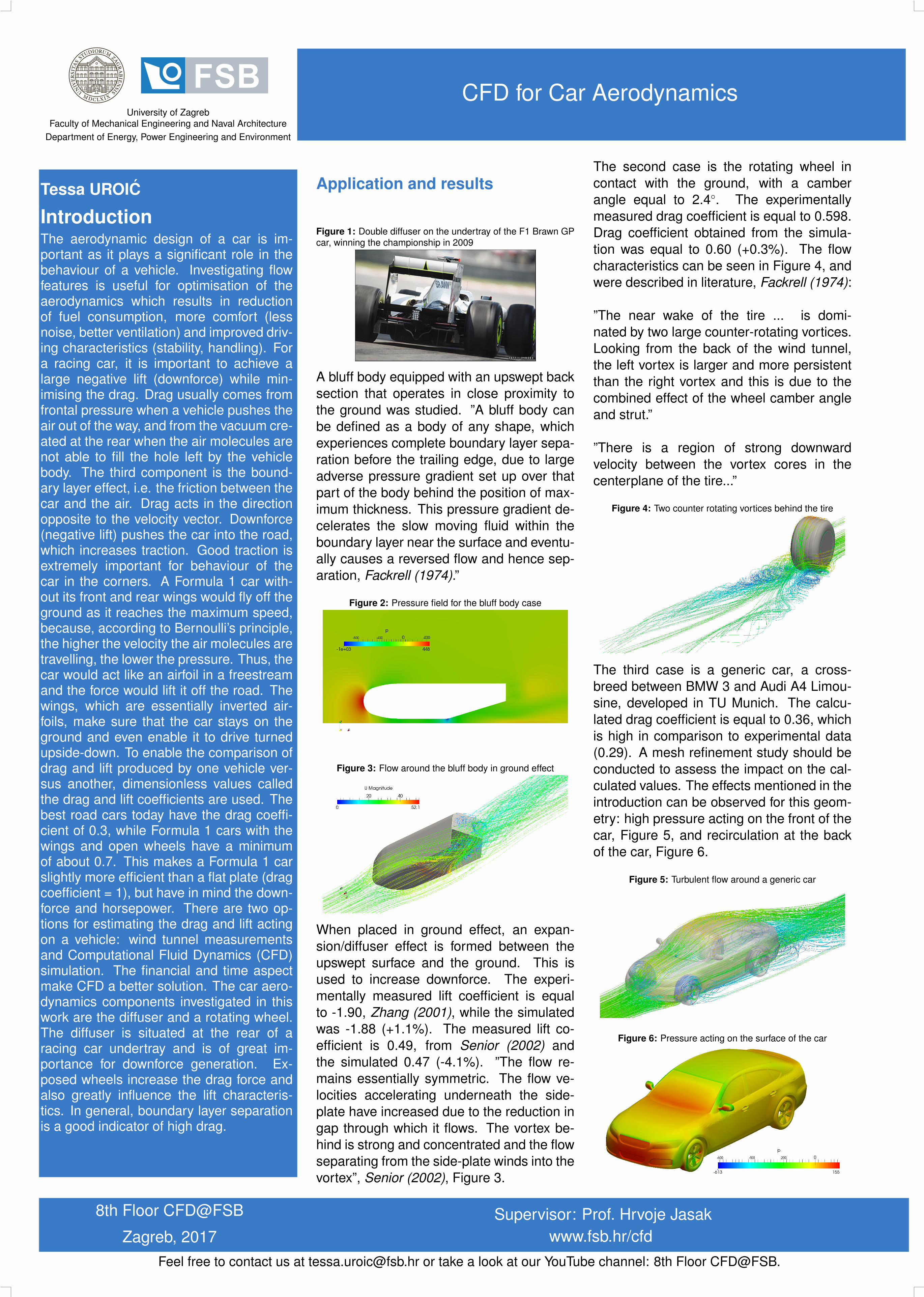
Figure 1: Double diffuser on the undertray of the F1 Brawn GPcar, winning the championship in 2009
A bluff body equipped with an upswept backsection that operates in close proximity tothe ground was studied. ”A bluff body canbe defined as a body of any shape, whichexperiences complete boundary layer sepa-ration before the trailing edge, due to largeadverse pressure gradient set up over thatpart of the body behind the position of max-imum thickness. This pressure gradient de-celerates the slow moving fluid within theboundary layer near the surface and eventu-ally causes a reversed flow and hence sep-aration, Fackrell (1974).”
Figure 2: Pressure field for the bluff body case
Figure 3: Flow around the bluff body in ground effect
When placed in ground effect, an expan-sion/diffuser effect is formed between theupswept surface and the ground. This isused to increase downforce. The experi-mentally measured lift coefficient is equalto -1.90, Zhang (2001), while the simulatedwas -1.88 (+1.1%). The measured lift co-efficient is 0.49, from Senior (2002) andthe simulated 0.47 (-4.1%). ”The flow re-mains essentially symmetric. The flow ve-locities accelerating underneath the side-plate have increased due to the reduction ingap through which it flows. The vortex be-hind is strong and concentrated and the flowseparating from the side-plate winds into thevortex”, Senior (2002), Figure 3.
The second case is the rotating wheel incontact with the ground, with a camberangle equal to 2.4◦. The experimentallymeasured drag coefficient is equal to 0.598.Drag coefficient obtained from the simula-tion was equal to 0.60 (+0.3%). The flowcharacteristics can be seen in Figure 4, andwere described in literature, Fackrell (1974):
”The near wake of the tire ... is domi-nated by two large counter-rotating vortices.Looking from the back of the wind tunnel,the left vortex is larger and more persistentthan the right vortex and this is due to thecombined effect of the wheel camber angleand strut.”
”There is a region of strong downwardvelocity between the vortex cores in thecenterplane of the tire...”
Figure 4: Two counter rotating vortices behind the tire
The third case is a generic car, a cross-breed between BMW 3 and Audi A4 Limou-sine, developed in TU Munich. The calcu-lated drag coefficient is equal to 0.36, whichis high in comparison to experimental data(0.29). A mesh refinement study should beconducted to assess the impact on the cal-culated values. The effects mentioned in theintroduction can be observed for this geom-etry: high pressure acting on the front of thecar, Figure 5, and recirculation at the backof the car, Figure 6.
Figure 5: Turbulent flow around a generic car
Figure 6: Pressure acting on the surface of the car
8th Floor CFD@FSB
Zagreb, 2017Supervisor: Prof. Hrvoje Jasak
www.fsb.hr/cfdFeel free to contact us at [email protected] or take a look at our YouTube channel: 8th Floor CFD@FSB.